WO2024070115A1 - 撮像装置 - Google Patents
撮像装置 Download PDFInfo
- Publication number
- WO2024070115A1 WO2024070115A1 PCT/JP2023/024904 JP2023024904W WO2024070115A1 WO 2024070115 A1 WO2024070115 A1 WO 2024070115A1 JP 2023024904 W JP2023024904 W JP 2023024904W WO 2024070115 A1 WO2024070115 A1 WO 2024070115A1
- Authority
- WO
- WIPO (PCT)
- Prior art keywords
- pixel
- signal
- row
- pixels
- output
- Prior art date
- Legal status (The legal status is an assumption and is not a legal conclusion. Google has not performed a legal analysis and makes no representation as to the accuracy of the status listed.)
- Ceased
Links
Images


Classifications
-
- H—ELECTRICITY
- H04—ELECTRIC COMMUNICATION TECHNIQUE
- H04N—PICTORIAL COMMUNICATION, e.g. TELEVISION
- H04N25/00—Circuitry of solid-state image sensors [SSIS]; Control thereof
- H04N25/60—Noise processing, e.g. detecting, correcting, reducing or removing noise
- H04N25/65—Noise processing, e.g. detecting, correcting, reducing or removing noise applied to reset noise, e.g. KTC noise related to CMOS structures by techniques other than CDS
-
- H—ELECTRICITY
- H04—ELECTRIC COMMUNICATION TECHNIQUE
- H04N—PICTORIAL COMMUNICATION, e.g. TELEVISION
- H04N25/00—Circuitry of solid-state image sensors [SSIS]; Control thereof
- H04N25/40—Extracting pixel data from image sensors by controlling scanning circuits, e.g. by modifying the number of pixels sampled or to be sampled
- H04N25/46—Extracting pixel data from image sensors by controlling scanning circuits, e.g. by modifying the number of pixels sampled or to be sampled by combining or binning pixels
-
- H—ELECTRICITY
- H04—ELECTRIC COMMUNICATION TECHNIQUE
- H04N—PICTORIAL COMMUNICATION, e.g. TELEVISION
- H04N25/00—Circuitry of solid-state image sensors [SSIS]; Control thereof
- H04N25/70—SSIS architectures; Circuits associated therewith
- H04N25/71—Charge-coupled device [CCD] sensors; Charge-transfer registers specially adapted for CCD sensors
- H04N25/75—Circuitry for providing, modifying or processing image signals from the pixel array
-
- H—ELECTRICITY
- H04—ELECTRIC COMMUNICATION TECHNIQUE
- H04N—PICTORIAL COMMUNICATION, e.g. TELEVISION
- H04N25/00—Circuitry of solid-state image sensors [SSIS]; Control thereof
- H04N25/70—SSIS architectures; Circuits associated therewith
- H04N25/76—Addressed sensors, e.g. MOS or CMOS sensors
- H04N25/77—Pixel circuitry, e.g. memories, A/D converters, pixel amplifiers, shared circuits or shared components
- H04N25/771—Pixel circuitry, e.g. memories, A/D converters, pixel amplifiers, shared circuits or shared components comprising storage means other than floating diffusion
-
- H—ELECTRICITY
- H04—ELECTRIC COMMUNICATION TECHNIQUE
- H04N—PICTORIAL COMMUNICATION, e.g. TELEVISION
- H04N25/00—Circuitry of solid-state image sensors [SSIS]; Control thereof
- H04N25/70—SSIS architectures; Circuits associated therewith
- H04N25/76—Addressed sensors, e.g. MOS or CMOS sensors
- H04N25/7795—Circuitry for generating timing or clock signals
-
- H—ELECTRICITY
- H04—ELECTRIC COMMUNICATION TECHNIQUE
- H04N—PICTORIAL COMMUNICATION, e.g. TELEVISION
- H04N25/00—Circuitry of solid-state image sensors [SSIS]; Control thereof
- H04N25/60—Noise processing, e.g. detecting, correcting, reducing or removing noise
- H04N25/616—Noise processing, e.g. detecting, correcting, reducing or removing noise involving a correlated sampling function, e.g. correlated double sampling [CDS] or triple sampling
-
- H—ELECTRICITY
- H04—ELECTRIC COMMUNICATION TECHNIQUE
- H04N—PICTORIAL COMMUNICATION, e.g. TELEVISION
- H04N25/00—Circuitry of solid-state image sensors [SSIS]; Control thereof
- H04N25/70—SSIS architectures; Circuits associated therewith
- H04N25/76—Addressed sensors, e.g. MOS or CMOS sensors
- H04N25/78—Readout circuits for addressed sensors, e.g. output amplifiers or A/D converters
Definitions
- This disclosure relates to an imaging device.
- CCD Charge Coupled Device
- CMOS Complementary Metal Oxide Semiconductor
- Patent Document 1 discloses an imaging device that forms a feedback path for each pixel in the imaging area and cancels reset noise through negative feedback.
- Patent document 2 discloses an imaging device with a high-speed pixel mixing function.
- An imaging device includes a plurality of pixels arranged in a matrix, signal lines provided for each column of the plurality of pixels, and a control circuit, each of the plurality of pixels including a photoelectric conversion unit that converts light into a signal charge, and the control circuit causes the plurality of pixels to output to the signal lines a pixel signal corresponding to the amount of the signal charge accumulated in the pixel and a reference signal after the pixel is reset, and during a first period during which a first pixel arranged in a first row outputs the pixel signal, the control circuit also causes a second pixel arranged in the first column in which the first pixel is arranged and arranged in a second row different from the first row to output the pixel signal, and causes the second pixel to output the pixel signal again after the first period and before resetting.
- FIG. 1 is a schematic diagram showing a configuration of an imaging device according to a first embodiment.
- FIG. 2 is a diagram showing a circuit configuration of the imaging device according to the first embodiment.
- FIG. 3 is a diagram showing a circuit configuration of a pixel in the imaging device according to the first embodiment.
- FIG. 4 is a timing chart of a first operation example of the imaging device according to the first embodiment.
- FIG. 5 is a timing chart of an operation example 2 of the imaging device according to the first embodiment.
- FIG. 6 is a timing chart of an operation example 3 of the imaging device according to the first embodiment.
- FIG. 7 is a timing chart of an operation example 4 of the imaging device according to the first embodiment.
- FIG. 8 is a diagram showing a circuit configuration of an imaging device according to the second embodiment.
- FIG. 9 is a timing chart of an example of the operation of the imaging device according to the second embodiment.
- Japanese Patent Application Laid-Open No. 2006-133693 discloses a technique for reducing reset noise by negative feedback. However, there is a demand for further noise reduction in imaging devices.
- the inventors focused on noise caused by an amplifier transistor that outputs a signal corresponding to the amount of signal charge generated by photoelectric conversion.
- Examples of noise caused by amplifier transistors include 1/f noise and thermal noise.
- the inventors investigated ways to reduce this noise, and arrived at the configuration disclosed herein.
- the imaging device includes a plurality of pixels arranged in a matrix, signal lines provided for each column of the plurality of pixels, and a control circuit, each of the plurality of pixels including a photoelectric conversion unit that converts light into a signal charge, and the control circuit causes the plurality of pixels to output to the signal lines a pixel signal corresponding to the amount of the signal charge accumulated in the pixel and a reference signal after the pixel is reset, and during a first period during which a first pixel arranged in a first row outputs the pixel signal, the control circuit also causes a second pixel arranged in the first column in which the first pixel is arranged and arranged in a second row different from the first row to output the pixel signal, and causes the second pixel to output the pixel signal again after the first period and before resetting.
- pixel signals from two rows of pixels, the first row and the second row are output simultaneously to the signal line and mixed.
- the effective gate width of the amplification transistor is doubled, and the mutual conductance gm of the amplification transistor is ⁇ 2 times.
- random noise caused by an amplification transistor is proportional to 1/gm. Therefore, low noise can be achieved by outputting pixel signals from two rows of pixels to the signal line simultaneously.
- the settling time is also proportional to 1/gm. Therefore, high-speed driving can be achieved by outputting pixel signals from two rows of pixels to the signal line simultaneously.
- an imaging device is the imaging device according to the first aspect, in which the control circuit resets the first pixel after causing it to output the pixel signal, and causes it to output the reference signal after the reset.
- the first pixel can continuously output the pixel signal and the reference signal, making it possible to perform signal processing using the pixel signal and the reference signal with a simple circuit configuration.
- an imaging device is the imaging device according to the first or second aspect, further comprising a signal processing circuit, and the signal processing circuit generates image data based on the pixel signals output by the first pixel and the second pixel during the first period and the reference signal output by the first pixel.
- image data can be generated using pixel signals that are a mixture of pixel signals from two rows of pixels, making it possible to generate image data with reduced noise.
- an imaging device is the imaging device according to the first aspect, in which the control circuit causes the first pixel to output the reference signal, accumulate the signal charge, and then output the pixel signal.
- the pixel signal of the first pixel is superimposed with reset noise equal to the previously output reference signal, so by subtracting the reference signal from the pixel signal, the effects of the reset noise can be removed, achieving even lower noise.
- an imaging device is an imaging device according to the first or fourth aspect, further comprising a signal processing circuit, and the signal processing circuit generates image data based on the reference signal output by the first pixel, the reference signal output by the second pixel, and the pixel signals output by the first pixel and the second pixel during the first period.
- image data can be generated using a pixel signal that is a mixture of pixel signals from two rows of pixels and a reference signal from two rows of pixels. Therefore, the effect of reset noise can be eliminated from the pixel signal that is a mixture of pixel signals from two rows of pixels by using the reference signal from two rows of pixels, achieving even lower noise.
- an imaging device is the imaging device according to the fifth aspect, further comprising a memory that stores a signal corresponding to the reference signal.
- an imaging device is an imaging device according to any one of the first to sixth aspects, in which the control circuit also outputs the pixel signal to a third pixel arranged in the first column and arranged in a third row different from the first row and the second row during the first period, and outputs the pixel signal to the third pixel again after the first period and before resetting.
- pixel signals from three rows of pixels, the first row, second row, and third row are simultaneously output to the signal line and mixed.
- the effective gate width of the amplification transistor becomes three times, and the mutual conductance gm of the amplification transistor becomes ⁇ 3 times. This makes it possible to achieve even lower noise and faster driving.
- an imaging device is an imaging device according to any one of the first to seventh aspects, further comprising a switch connected between the signal line provided in the first column and the signal line provided in a second column different from the first column, and the control circuit causes the switch to be conductive during the first period.
- an imaging device is an imaging device according to any one of the first to eighth aspects, in which each of the plurality of pixels includes a feedback circuit that negatively feeds back reset noise.
- an imaging device is an imaging device according to any one of the first to ninth aspects, in which the control circuit does not cause the second pixel to output the reference signal during a second period in which the control circuit causes the first pixel to output the reference signal.
- each figure is a schematic diagram and is not necessarily an exact illustration. Therefore, for example, the scale of each figure does not necessarily match.
- Fig. 1 is a schematic diagram showing the configuration of an image pickup device according to the present embodiment.
- the imaging device 100 includes a plurality of pixels 10, each of which includes a photoelectric conversion unit supported on a semiconductor substrate 110, row control lines L, vertical signal lines C, and peripheral circuits.
- the vertical signal lines C are an example of a signal line.
- the multiple pixels 10 are arranged, for example, two-dimensionally on the semiconductor substrate 110 to form an imaging area.
- the multiple pixels 10 are arranged in a matrix.
- the number and arrangement of the pixels 10 are not limited to the example shown in FIG. 1 and are arbitrary. For example, by arranging the multiple pixels 10 one-dimensionally (i.e., when there is one row or column), the imaging device 100 can be used as a line sensor.
- the peripheral circuits include a row scanning circuit 120, a signal processing circuit 130, a control circuit 140, a voltage supply circuit 150, and a memory 170.
- the peripheral circuits may be provided on the semiconductor substrate 110, or a part of the peripheral circuits may be provided on another substrate.
- the row scanning circuit 120 is connected to each pixel 10 via a row control line L.
- a row control line L is provided for each row of pixels 10, and is electrically connected to one or more pixels 10 belonging to the same row.
- Each row control line L is connected to the row scanning circuit 120. For ease of viewing, only one row control line L is shown for each row in FIG. 1, but as described below, the row control line L may include two or more control lines for each row.
- the row scanning circuit 120 applies a predetermined voltage to the row control line L to select the pixels 10 on a row-by-row basis, and causes the pixels 10 to output signals and perform reset operations, etc.
- the signal processing circuit 130 is connected to each pixel 10 via a vertical signal line C.
- a vertical signal line C is provided for each column of pixels 10, and is electrically connected to one or more pixels 10 belonging to the same column.
- Each vertical signal line C is connected to the signal processing circuit 130. Note that two or more vertical signal lines C may be provided in the same column.
- Signals from the pixels 10 selected row by row by the row scanning circuit 120 are output to the signal processing circuit 130 via the vertical signal line C.
- the pixels 10 output pixel signals corresponding to the signal charges accumulated in the pixels 10 and a post-reset reference signal, which is a signal corresponding to the potential of the pixels 10 after reset, to the vertical signal line C.
- the signal processing circuit 130 performs various signal processing on the signals output from the pixels 10, such as noise suppression signal processing represented by correlated double sampling and analog-to-digital conversion (AD conversion).
- the signal processing circuit 130 generates image data based on the signals from the pixels 10 and outputs the generated image data. In other words, the signals from the pixels 10 are read out by the signal processing circuit 130 as image signals indicating the image data.
- the signal processing circuit 130 sequentially outputs image signals for each read-out row of the multiple pixels 10.
- image signal refers to an output signal that is read out based on the signal output through the vertical signal line C and is used to form an image.
- the signal processing circuit 130 may include, for example, a noise suppression signal processing circuit, a sample-and-hold circuit, an analog-to-digital conversion circuit, and a parallel-serial conversion circuit.
- the signal processing circuit 130 may also include a processor.
- the control circuit 140 receives, for example, command data and a clock provided from outside the imaging device 100, and controls the entire imaging device 100.
- the control circuit 140 has, for example, a timing generator, and supplies drive signals to the row scanning circuit 120, the signal processing circuit 130, the voltage supply circuit 150, and the like.
- the control circuit 140 may include a processor.
- the voltage supply circuit 150 is electrically connected to each pixel 10, for example, by being connected to a bias control line 42.
- the voltage supply circuit 150 supplies a predetermined voltage to each pixel 10 via the bias control line 42 when the imaging device 100 is operating.
- the voltage supply circuit 150 is configured to be able to switch between, for example, at least two or more different voltages and apply them to the bias control line 42.
- the voltage output from the voltage supply circuit 150 may be changed in a stepwise manner or continuously.
- the voltage supply circuit 150 is not limited to a specific power supply circuit, and may be a circuit that converts a voltage supplied from a power source such as a battery into a predetermined voltage, or a circuit that outputs one of multiple power sources, or a circuit that generates a predetermined voltage.
- the voltage supply circuit 150 may be part of the row scanning circuit 120 described above.
- the memory 170 is a frame memory that stores signals corresponding to signals output by the pixels 10. For example, a signal corresponding to a reference signal output by the pixels 10 is stored in the memory 170.
- the signal processing circuit 130 temporarily stores signals such as the reference signal in the memory 170, and generates image data using the signals stored in the memory.
- the memory 170 may also store programs executed by the signal processing circuit 130 and the control circuit 140. Note that if the signal processing circuit 130 does not use signals stored in the memory 170 when generating image data, the imaging device 100 does not need to include the memory 170.
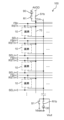
- FIG. 2 is a diagram showing the circuit configuration of the imaging device 100.
- FIG. 3 is a diagram showing the circuit configuration of a pixel 10 in the imaging device 100. Note that FIG. 2 shows the circuit configuration of the imaging device 100, focusing on the control lines and signal lines connected to the pixel 10. For this reason, some circuit elements are not shown in FIG. 2. Also, the circuit configuration within the pixel 10 in FIG. 2 is shown in FIG. 3.
- Each pixel 10 is connected to a power supply line 70.
- An address control line SEL, a reset control line RST, and a feedback control line FB are provided for each row of pixels 10.
- the address control line SEL, the reset control line RST, and the feedback control line FB correspond to the row control line L described above.
- the address control line SEL, the reset control line RST, and the feedback control line FB are each electrically connected to one or more pixels 10 belonging to the same row.
- the characters n, n+1, etc. added after the reference symbols of the address control line SEL, the reset control line RST, and the feedback control line FB represent the row of the pixel 10, where n is an integer of 0 or more, such as 0 or 1.
- the address control line SELn represents that it is the address control line SELn connected to the pixel 10 in the nth row.
- the characters m, etc. added after the reference symbols of the vertical signal lines C represent the column of the pixel 10, where m is an integer of 0 or more, such as 0 or 1.
- vertical signal line Cm indicates that the vertical signal line C is connected to the pixel 10 in the mth column.
- Each pixel 10 has a photoelectric conversion unit 13, an amplifier transistor 24, an address transistor 26, a reset transistor 28, a band control transistor 81, a capacitance element 82, and a capacitance element 83.
- the photoelectric conversion unit 13 receives incident light and generates a signal.
- the photoelectric conversion unit 13 is, for example, stacked on the semiconductor substrate 110.
- the photoelectric conversion unit 13 does not need to be an independent element for each pixel 10 in its entirety, and for example, a portion of the photoelectric conversion unit 13 may span multiple pixels 10.
- the photoelectric conversion unit 13 of each pixel 10 is further connected to a bias control line 42 and a predetermined voltage is applied to it. As described above, the bias control line 42 is connected to the voltage supply circuit 150.
- the amplification transistor 24, address transistor 26, reset transistor 28, and band control transistor 81 are, for example, field effect transistors (FETs).
- FETs field effect transistors
- N-channel MOSFETs Metal Oxide Semiconductor Field Effect Transistors
- the control terminal is, for example, a gate electrode.
- the input terminal is one of the drain and source, for example, the drain.
- the output terminal is the other of the drain and source, for example, the source.
- the control terminal which is the gate electrode of the amplification transistor 24, is connected to the photoelectric conversion unit 13.
- the signal charge generated by the photoelectric conversion unit 13 is accumulated in the charge accumulation unit 71 between the gate electrode of the amplification transistor 24 and the photoelectric conversion unit 13.
- the signal charge is a hole or an electron.
- the charge storage section 71 includes, for example, a node connected to the gate electrode of the amplification transistor 24.
- the charge storage section 71 is also called a "floating diffusion node.” The structure of the photoelectric conversion section 13 will be described in detail later.
- the input terminal of the amplifying transistor 24 is connected to the power supply line 70.
- the power supply line 70 is connected to the switch S1b and the switch R1.
- the switch S1b controls whether or not to connect the power supply line 70 to the analog power supply AVDD.
- the switch R1 controls whether or not to connect the power supply line 70 to the constant current source 90 that flows from the analog power supply AVDD.
- the output terminal of the amplifying transistor 24 is connected to the input terminal of the address transistor 26.
- the output terminal of the address transistor 26 is connected to a vertical signal line C.
- the vertical signal line C is connected to a switch R1b, a switch S1, and a signal processing circuit 130 (see FIG. 1).
- the switch R1b controls whether or not to connect the vertical signal line C to a constant current source 30 connected to an analog ground.
- the switch S1 controls whether or not to connect the vertical signal line C to a voltage Vbias.
- the switch R1b, the switch S1, and the constant current source 30 are provided for each column of multiple pixels 10.
- Switch S1b, switch R1, switch R1b, and switch S1 are, for example, field effect transistors.
- the operation of switch S1b, switch R1, switch R1b, and switch S1 is, for example, controlled by control circuit 140.
- the power supply line 70 functions as a source follower power supply.
- the amplifier transistor 24 amplifies and outputs the potential of the charge storage section 71.
- a signal Vout which is a source follower output according to the potential of the gate of the amplifier transistor 24, is output to the signal processing circuit 130 via the vertical signal line C as a pixel signal or a reference signal.
- the output terminal of the amplifying transistor 24 is connected to the input terminal of the address transistor 26.
- the output terminal of the address transistor 26 is connected to the vertical signal line C.
- the control terminal of the address transistor 26 is connected to the address control line SEL. By controlling the potential of the address control line SEL, the output of the amplifying transistor 24 can be selectively output to the vertical signal line C for multiple pixels 10.
- the address control line SEL is connected to a row scanning circuit 120 (see FIG. 1).
- the row scanning circuit 120 applies a predetermined voltage to the address control line SEL to select a plurality of pixels 10 arranged in each row on a row-by-row basis. This causes the signal of the selected pixel 10 to be output.
- the reset transistor 28 is connected between the band control transistor 81 and the charge storage section 71.
- the control terminal of the reset transistor 28 is connected to a reset control line RST. By controlling the potential of the reset control line RST, the potential of the charge storage section 71 of the pixel 10 can be reset.
- the band control transistor 81 is connected between the power line 70 and the reset transistor 28, and constitutes an in-pixel feedback amplifier during a reset operation.
- the input terminal of the band control transistor 81 is connected to the power line 70.
- the output terminal of the band control transistor 81 is connected to the input terminal of the reset transistor 28, one end of the capacitance element 82, and one end of the capacitance element 83.
- the feedback control line FB is connected to the control terminal of the band control transistor 81 and the row scanning circuit 120 (see FIG. 1).
- the state of the band control transistor 81 is determined by the potential of the feedback control line FB. For example, by controlling the potential of the feedback control line FB, a feedback path is formed by the charge storage unit 71, the amplification transistor 24, and the band control transistor 81.
- the pixel 10 includes a feedback circuit that negatively feeds back reset noise.
- the capacitance elements 82 and 83 function as negative feedback capacitances when resetting the potential of the charge storage section 71 in the in-pixel feedback amplifier, and reduce reset noise when resetting the potential of the charge storage section 71.
- One end of the capacitance element 82 is connected to one end of the capacitance element 83, the input terminal of the reset transistor 28, and the output terminal of the band control transistor 81.
- the other end of the capacitance element 82 is applied with, for example, a reference voltage VR.
- One end of the capacitance element 83 is connected to one end of the capacitance element 82, the input terminal of the reset transistor 28, and the output terminal of the band control transistor 81.
- the other end of the capacitance element 83 is connected to the control terminal of the amplification transistor 24 and the output terminal of the reset transistor 28.
- the capacitance elements 82 and 83 are, for example, MIM (Metal Insulator Metal) capacitances or MIS (Metal Insulator Semiconductor) capacitances.
- the photoelectric conversion unit 13 includes a pixel electrode 11, a counter electrode 12, and a photoelectric conversion layer 15 disposed between the pixel electrode 11 and the counter electrode 12.
- the pixel electrode 11, the photoelectric conversion layer 15, and the counter electrode 12 are stacked in this order on the semiconductor substrate 110, for example.
- the photoelectric conversion unit 13 may further include other elements such as an electron blocking layer and a hole blocking layer.
- the counter electrode 12 and the photoelectric conversion layer 15 are formed, for example, across multiple pixels 10.
- a pixel electrode 11 is provided for each pixel 10.
- the pixel electrode 11 is electrically isolated from the pixel electrodes 11 of the other pixels 10.
- At least one of the counter electrode 12 and the photoelectric conversion layer 15 may be provided separately for one or more pixels 10.
- the pixel electrode 11 is electrically connected to the photoelectric conversion layer 15 and is an electrode for collecting signal charges generated in the photoelectric conversion layer 15.
- the pixel electrode 11 is connected to the charge accumulation section 71.
- the pixel electrode 11 is formed using a conductive material. The signal charges collected by the pixel electrode 11 are accumulated in the charge accumulation section 71.
- the counter electrode 12 is, for example, a transparent electrode made of a transparent conductive material.
- the counter electrode 12 is disposed on the side of the photoelectric conversion layer 15 where light is incident.
- the counter electrode 12 is connected to the voltage supply circuit 150 shown in FIG. 1 via the bias control line 42.
- the voltage supply circuit 150 controls the potential of the counter electrode 12 relative to the potential of the pixel electrode 11, so that either the holes or the electrons of the hole-electron pairs generated in the photoelectric conversion layer 15 by photoelectric conversion can be collected by the pixel electrode 11 as signal charges.
- the pixel electrode 11 can selectively collect the holes by making the counter electrode 12 higher in potential than the pixel electrode 11. It is also possible to selectively collect electrons by the pixel electrode 11 by making the counter electrode 12 lower in potential than the pixel electrode 11.
- the photoelectric conversion layer 15 is a layer that absorbs photons and generates photocharges that become signal charges. Specifically, the photoelectric conversion layer 15 receives incident light and generates hole-electron pairs. That is, the signal charge is either a hole or an electron. For example, when holes are used as the signal charge, the holes are collected by the pixel electrode 11. Electrons, which are charges of the opposite polarity to the signal charge, are collected by the counter electrode 12.
- the photoelectric conversion layer 15 is made of a photoelectric conversion material, and is formed, for example, from an organic semiconductor material. The photoelectric conversion layer 15 may also be formed from an inorganic semiconductor material.
- circuit configuration of pixel 10 is not limited to the example described using Figures 2 and 3, and various circuit configurations of pixels of imaging devices described in Patent Document 1, etc., can be applied.
- FIG. 4 is a timing chart of a first operation example of the imaging device 100.
- FIG. 4 shows changes in the potentials of the address control line SEL and the reset control line RST of the nth row to the n+3th row of a plurality of pixels 10.
- the address transistor 26 is conductive when the potential of the address control line SEL is at a high level, and is non-conductive when the potential of the address control line SEL is at a low level.
- the reset transistor 28 is conductive when the potential of the reset control line RST is at a high level, and is non-conductive when the potential of the reset control line RST is at a low level.
- the operation of the pixel 10 in the mth column and the corresponding peripheral circuit will be explained, but similar operations are performed for the pixels 10 in other columns.
- the mth column of the multiple pixels 10 is an example of a first column.
- the nth row of the multiple pixels 10 is an example of a first row.
- the n+1th row of the multiple pixels 10 is an example of a second row different from the first row.
- the pixel 10 arranged in the nth row and mth column is an example of a first pixel.
- the pixel 10 arranged in the n+1th row and mth column is an example of a second pixel.
- a plurality of pixels 10 are exposed to light, and the signal charge generated by the photoelectric conversion unit 13 is accumulated in the charge accumulation unit 71 of each pixel 10.
- the exposure of the plurality of pixels 10 is performed, for example, by a global shutter method.
- the voltage supply circuit 150 supplies a first voltage to the counter electrode 12 such that the potential of the counter electrode 12 is sufficiently higher than that of the pixel electrode 11.
- holes, which are signal charges generated by photoelectric conversion of the photoelectric conversion layer 15 move to the pixel electrode 11 and are accumulated in the charge accumulation unit 71.
- the voltage supply circuit 150 supplies a second voltage to the counter electrode 12 such that the movement of signal charges does not substantially occur in the photoelectric conversion unit 13.
- the voltage supply circuit 150 supplies the counter electrode 12 with a second voltage that makes the potential difference between the pixel electrode 11 and the counter electrode 12 smaller than when the first voltage is supplied, for example, such that the potential difference is close to zero (for example, 1 V or less).
- the exposure of the multiple pixels 10 may be performed by a rolling shutter method.
- the same first voltage as during exposure is supplied to the counter electrode 12 even after exposure, and the exposure period is from when the pixel 10 is reset to when the first pixel signal is output.
- the pixel 10 may be reset again after being reset immediately before outputting the reference signal.
- the potential of the address control line SELn becomes high level, and the address transistor 26 of the pixel 10 in the nth row becomes conductive. In other words, the pixel 10 in the nth row becomes selected.
- the switch S1 is turned off, the switch S1b is turned on, the switch R1 is turned off, and the switch R1b is turned on.
- a pixel signal corresponding to the amount of signal charge accumulated in the charge accumulation section 71 of the pixel 10 in the nth row is output to the vertical signal line Cm.
- the potential of the address control line SELn+1 also becomes high level, and the address transistor 26 of the pixel 10 in the n+1th row also becomes conductive.
- the pixel 10 in the n+1th row becomes selected.
- a pixel signal corresponding to the amount of signal charge accumulated in the charge accumulation section 71 of the pixel 10 in the n+1th row is output to the vertical signal line Cm.
- the pixel signal output by the pixel 10 in the nth row and the pixel signal output by the pixel 10 in the n+1th row are mixed on the vertical signal line Cm.
- the signal processing circuit 130 reads out the pixel signal output to the vertical signal line Cm.
- the signal processing circuit 130 temporarily holds a voltage level corresponding to the pixel signal output to the vertical signal line Cm.
- the signal processing circuit 130 may include a capacitive element for holding this voltage level.
- the pixel signal read out to the signal processing circuit 130 is designated as Sn_n+1.
- the potential of the reset control line RSTn becomes high level, and the reset transistor 28 of the pixel 10 in the nth row becomes conductive.
- the potential of the feedback control line FBn also becomes high level, and the band control transistor 81 also becomes conductive.
- the switch S1 turns on, the switch S1b turns off, the switch R1 turns on, and the switch R1b turns off.
- the amplification transistor 24, the vertical signal line Cm, the power supply line 70, and the constant current source 90 beyond it form a source-grounded amplifier. This resets the pixel 10 in the nth row.
- the potential of the charge storage unit 71 of the pixel 10 in the nth row is reset to Vbias.
- the potential of the address control line SELn+1 goes to low level, and the address transistor 26 of the pixel 10 in the n+1th row goes into a non-conducting state. In other words, the pixel 10 in the n+1th row goes into a non-selected state. Furthermore, the potential of the reset control line RSTn+1 remains at low level. Therefore, the pixel 10 in the n+1th row is not reset.
- the potential of the reset control line RSTn becomes low level, and the reset transistor 28 of the pixel 10 in the nth row becomes non-conductive.
- the potential of the feedback control line FBn becomes an intermediate potential between high level and low level, and the band control transistor 81 functions as a resistance circuit to form a negative feedback amplifier.
- the switch S1 is turned off, the switch S1b is turned on, the switch R1 is turned off, and the switch R1b is turned on.
- a reference signal which is a signal after the reset of the pixel 10 in the nth row, that is, a reference signal corresponding to the potential of the reset charge storage unit 71, is output to the vertical signal line Cm.
- the pixel 10 in the nth row is reset after outputting the pixel signal, and outputs the reference signal after the reset.
- the signal of the pixel 10 in the n+1th row is not output to the vertical signal line Cm. In other words, only the reference signal of the pixel 10 in the nth row is output to the vertical signal line Cm.
- the reset of pixel 10 may be completed by the potential of feedback control line FBn becoming low level without taking an intermediate potential between high level and low level. Also, if pixel 10 does not have a configuration that includes a feedback circuit, the reset is completed at time t4.
- the signal processing circuit 130 reads out the reference signal output to the vertical signal line Cm.
- the reference signal read out to the signal processing circuit 130 is designated as Rn.
- the signal processing circuit 130 then generates an image signal for the pixel 10 in the nth row.
- the image signal for the pixel 10 in the nth row is obtained as a differential signal (Sn_n+1-Rn) between the pixel signal Sn_n+1 and the reference signal Rn.
- the signal processing circuit 130 obtains the differential signal, for example, from the output voltage difference between the voltage corresponding to the pixel signal Sn_n+1 and the voltage corresponding to the reference signal Rn.
- the potential of the address control line SELn becomes low level, and the address transistor 26 of the pixel 10 in the nth row becomes non-conductive. In other words, the pixel 10 in the nth row becomes unselected.
- the potential of the address control line SELn+1 becomes high level, and the address transistor 26 of the pixel 10 in the n+1th row becomes conductive. That is, the pixel 10 in the n+1th row becomes selected.
- the switch S1 turns off, the switch S1b turns on, the switch R1 turns off, and the switch R1b turns on.
- a pixel signal corresponding to the amount of signal charge accumulated in the charge accumulation section 71 of the pixel 10 in the n+1th row is output to the vertical signal line Cm.
- the pixel signal of the pixel 10 in the n+1th row is output from time t1 to time t3, but it is output in a non-destructive manner, and the pixel 10 in the n+1th row is not reset. Therefore, the pixel 10 in the n+1th row can output a pixel signal again. Also, since the voltage supply circuit 150 applies to the opposing electrode 12 a second voltage that does not substantially accumulate signal charge in the charge accumulation section 71, the output value of the pixel signal of the pixel 10 in the n+1th row does not change even if time passes.
- the potential of the address control line SELn+2 also goes high, and the address transistor 26 of the pixel 10 in the n+2th row also goes conductive.
- the pixel 10 in the n+2th row goes into a selected state.
- a pixel signal corresponding to the amount of signal charge accumulated in the charge accumulation section 71 of the pixel 10 in the n+2th row is output to the vertical signal line Cm.
- the pixel signal output by the pixel 10 in the n+1th row and the pixel signal output by the pixel 10 in the n+2th row are mixed on the vertical signal line Cm.
- the signal processing circuit 130 reads out the pixel signal output to the vertical signal line Cm.
- the pixel signal read out by the signal processing circuit 130 is designated as Sn+1_n+2.
- the potential of the reset control line RSTn+1 goes high, and the reset transistor 28 of the pixel 10 in the n+1th row goes into a conductive state.
- the potential of the feedback control line FBn+1 also goes high, and the band control transistor 81 also goes into a conductive state.
- the switch S1 turns on, the switch S1b turns off, the switch R1 turns on, and the switch R1b turns off. This resets the pixel 10 in the n+1th row.
- the potential of the charge storage unit 71 of the pixel 10 in the n+1th row is reset to Vbias.
- the potential of the address control line SELn+2 goes to low level, and the address transistor 26 of the pixel 10 in the n+2th row goes into a non-conducting state. In other words, the pixel 10 in the n+2th row goes into a non-selected state. Furthermore, the potential of the reset control line RSTn+2 remains at low level. Therefore, the pixel 10 in the n+2th row is not reset.
- the potential of the reset control line RSTn+1 becomes low level, and the reset transistor 28 of the pixel 10 in the n+1th row becomes non-conductive.
- the potential of the feedback control line FBn+1 becomes an intermediate potential between high level and low level, and the band control transistor 81 functions as a resistance circuit to form a negative feedback amplifier.
- the band control transistor 81 becomes non-conductive, and the reset of the potential of the charge storage unit 71 is completed.
- the switch S1 is turned off, the switch S1b is turned on, the switch R1 is turned off, and the switch R1b is turned on.
- the reference signal which is the signal after the reset of the pixel 10 in the n+1th row, is output to the vertical signal line Cm.
- the signal of the pixel 10 in the n+2th row is not output to the vertical signal line Cm. In other words, only the reference signal of the pixel 10 in the n+1th row is output to the vertical signal line Cm.
- the signal processing circuit 130 reads out the reference signal output to the vertical signal line Cm.
- the reference signal read out to the signal processing circuit 130 is set to Rn+1.
- the signal processing circuit 130 generates an image signal for the pixel 10 in the n+1th row.
- the image signal for the pixel 10 in the n+1th row is obtained as a differential signal (Sn+1_n+2-Rn+1) between the pixel signal Sn+1_n+2 and the reference signal Rn+1.
- the potential of the address control line SELn+1 goes to low level, and the address transistor 26 of the pixel 10 in the n+1th row goes into a non-conducting state. In other words, the pixel 10 in the n+1th row goes into a non-selected state.
- the potential of the address control line SELn+2 goes high, and the address transistor 26 of the pixel 10 in the n+2th row becomes conductive. In other words, the pixel 10 in the n+2th row becomes selected. Thereafter, in all rows of the pixels 10 from the n+2th row onwards, the same operation as the nth and n+1th rows described above is performed for each row of the pixels 10. As a result, image signals for pixels in the same number of rows as the number of rows of the pixels 10 are output from the signal processing circuit 130.
- the pixels 10 sequentially output pixel signals and reference signals to the vertical signal line Cm for each readout row consisting of one row of the pixels 10. Also, during the first period (from time t1 to time t3) in which the pixels 10 in the nth row, which is the readout row, output pixel signals, the pixels 10 in the n+1th row, which is the readout row after the nth row, also output pixel signals. Also, during the second period (from a predetermined time between times t4 and t5 to time t6) in which the pixels 10 in the nth row output reference signals, the pixels 10 in the n+1th row do not output reference signals.
- the pixels 10 in the n+1th row output pixel signals again before resetting.
- the signal processing circuit 130 generates image data based on the pixel signals Sn_n+1 output by the pixels 10 in the nth row and the pixels 10 in the n+1th row to the vertical signal line Cm during the first period, and the reference signal Rn output by the pixels 10 in the nth row to the vertical signal line Cm.
- the pixel signals of the pixels 10 of two rows are simultaneously output to the vertical signal line Cm and mixed.
- the effective gate width of the amplifying transistor 24 is doubled, and the mutual conductance gm of the amplifying transistor 24 is ⁇ 2 times.
- the random noise caused by the amplifying transistor 24 is proportional to 1/gm. Therefore, it is possible to realize low noise by simultaneously outputting the pixel signals of the pixels 10 of two rows to the vertical signal line Cm.
- the settling time is also proportional to 1/gm. Therefore, it is possible to realize high-speed driving by simultaneously outputting the pixel signals of the pixels 10 of two rows to the vertical signal line Cm. For example, it is possible to set the time from time t1 to time t2 to be shorter.
- the term "readout row” refers to a row with a different concept from the row from which the pixels 10 output signals, and is a row of multiple pixels 10 from which signals are read out as an image signal by the signal processing circuit 130.
- the readout row is a row of multiple pixels 10 that corresponds one-to-one to the row of pixels in the image signal (image data) output by the signal processing circuit 130.
- the above effect can be obtained by outputting pixel signals from pixels 10 in a row other than the readout row at the same time as the pixels 10 in the readout row.
- the "next readout row" when obtaining a color image is the next readout row of pixels 10 of the same color.
- Operation example 2 Next, a description will be given of an operation example 2 of the imaging device 100. In the following description of the operation example 2, differences from the operation example 1 will be mainly described, and descriptions of commonalities will be omitted or simplified.
- the operation example 2 is an example of an operation in which the signal processing circuit 130 generates an image signal using a reference signal stored in the memory 170.
- FIG. 5 is a timing chart of operation example 2 of the imaging device 100. The same items as in FIG. 4 are shown in FIG. 5.
- operation example 2 the operation of the pixel 10 in the mth column and the corresponding peripheral circuitry will be described, but similar operations are also performed for the pixels 10 in the other columns.
- the potential of the address control line SELn goes high, and the address transistor 26 of the pixel 10 in the nth row goes into a conductive state.
- the potential of the reset control line RSTn goes high, and the reset transistor 28 of the pixel 10 in the nth row goes into a conductive state.
- the potential of the feedback control line FBn also goes high, and the band control transistor 81 also goes into a conductive state.
- the switch S1 is turned on, the switch S1b is turned off, the switch R1 is turned on, and the switch R1b is turned off. This resets the pixel 10 in the nth row.
- the potential of the reset control line RSTn becomes low level, and the reset transistor 28 of the pixel 10 in the nth row becomes non-conductive.
- the potential of the feedback control line FBn becomes an intermediate potential between high level and low level.
- the band control transistor 81 becomes non-conductive, and the reset of the potential of the charge storage unit 71 is completed.
- the switch S1 is turned off, the switch S1b is turned on, the switch R1 is turned off, and the switch R1b is turned on.
- the reference signal after the reset of the pixel 10 in the nth row is output to the vertical signal line Cm.
- the signal of the pixel 10 in the n+1th row is not output to the vertical signal line Cm. In other words, only the reference signal of the pixel 10 in the nth row is output to the vertical signal line Cm.
- the signal processing circuit 130 reads out the reference signal output to the vertical signal line Cm.
- the reference signal read out by the signal processing circuit 130 is designated as Rn.
- the signal processing circuit 130 stores the read out reference signal Rn in the memory 170.
- the signal processing circuit 130 stores, for example, the digital value of the reference signal Rn after AD conversion in the memory 170.
- the potential of the address control line SELn becomes low level, and the address transistor 26 of the pixel 10 in the nth row becomes non-conductive.
- the potential of the address control line SELn+1 goes high, and the address transistor 26 of the pixel 10 in the n+1th row goes into a conductive state.
- the potential of the reset control line RSTn+1 goes high, and the reset transistor 28 of the pixel 10 in the n+1th row goes into a conductive state.
- the potential of the feedback control line FBn+1 also goes high, and the band control transistor 81 goes into a conductive state.
- the switch S1 goes on, the switch S1b goes off, the switch R1 goes on, and the switch R1b goes off. This resets the pixel 10 in the n+1th row.
- the potential of the reset control line RSTn+1 becomes low level, and the reset transistor 28 of the pixel 10 in the n+1th row becomes non-conductive.
- the potential of the feedback control line FBn+1 becomes an intermediate potential between high level and low level.
- the band control transistor 81 becomes non-conductive, and the reset of the potential of the charge storage unit 71 is completed.
- the switch S1 is turned off, the switch S1b is turned on, the switch R1 is turned off, and the switch R1b is turned on.
- the reference signal after reset of the pixel 10 in the n+1th row is output to the vertical signal line Cm.
- the signal of the pixel 10 in the n+2th row is not output to the vertical signal line Cm. In other words, only the reference signal of the pixel 10 in the n+1th row is output to the vertical signal line Cm.
- the signal processing circuit 130 reads out the reference signal output to the vertical signal line Cm.
- the reference signal read out by the signal processing circuit 130 is assumed to be Rn+1.
- the signal processing circuit 130 stores the read out reference signal Rn+1 in the memory 170.
- the signal processing circuit 130 stores, for example, the digital value of the reference signal Rn+1 after AD conversion in the memory 170.
- the potential of the address control line SELn becomes high level, and the address transistor 26 of the pixel 10 in the nth row becomes conductive.
- the switch S1 is turned off, the switch S1b is turned on, the switch R1 is turned off, and the switch R1b is turned on.
- a pixel signal corresponding to the amount of signal charge accumulated in the charge accumulation section 71 of the pixel 10 in the nth row is output to the vertical signal line Cm.
- the potential of the address control line SELn+1 goes high, and the address transistor 26 of the pixel 10 in the n+1th row becomes conductive.
- This causes a pixel signal corresponding to the amount of signal charge accumulated in the charge accumulation section 71 of the pixel 10 in the n+1th row to be output to the vertical signal line Cm.
- the pixel signal output by the pixel 10 in the nth row and the pixel signal output by the pixel 10 in the n+1th row are mixed on the vertical signal line Cm.
- the signal processing circuit 130 reads out the pixel signal output to the vertical signal line Cm.
- the pixel signal read out to the signal processing circuit 130 is designated as Sn_n+1.
- the signal processing circuit 130 then generates an image signal for the pixel 10 in the nth row.
- the image signal for the pixel 10 in the nth row is obtained as a difference signal between the pixel signal Sn_n+1 and the average value of the reference signal Rn and the reference signal Rn+1.
- the signal processing circuit 130 After AD conversion of the read pixel signal Sn_n+1, the signal processing circuit 130 refers to the reference signal Rn and the reference signal Rn+1 stored in the memory 170, and performs a calculation process to subtract the average value of the reference signal Rn and the reference signal Rn+1 from the pixel signal Sn_n+1, thereby acquiring the image signal for the pixel 10 in the nth row.
- the potential of the address control line SELn becomes low level, and the address transistor 26 of the pixel 10 in the nth row becomes non-conductive.
- the potential of the address control line SELn+1 remains high level, and the address transistor 26 of the pixel 10 in the n+1th row continues to be in a conductive state. Therefore, even at time t11, the pixel signal of the pixel 10 in the n+1th row is still output to the vertical signal line Cm.
- the potential of the address control line SELn+2 goes high, and the address transistor 26 of the pixel 10 in the n+2th row becomes conductive.
- This causes a pixel signal corresponding to the amount of signal charge accumulated in the charge accumulation section 71 of the pixel 10 in the n+2th row to be output to the vertical signal line Cm.
- the pixel signal output by the pixel 10 in the n+1th row and the pixel signal output by the pixel 10 in the n+2th row are mixed on the vertical signal line Cm.
- the signal processing circuit 130 reads out the pixel signal output to the vertical signal line Cm.
- the pixel signal read out to the signal processing circuit 130 is set as Sn+1_n+2.
- the signal processing circuit 130 generates an image signal for the pixel 10 in the n+1th row.
- the image signal for the pixel 10 in the n+1th row is obtained as a difference signal between the pixel signal Sn+1_n+2 and the average value of the reference signal Rn+1 and the reference signal Rn+2.
- the signal processing circuit 130 refers to the reference signal Rn+1 stored in the memory 170 and the reference signal Rn+2 of the pixel 10 in the n+2th row, and performs a calculation process to subtract the average value of the reference signal Rn+1 and the reference signal Rn+2 from the pixel signal Sn+1_n+2, thereby acquiring the image signal for the pixel 10 in the n+1th row.
- the signal processing circuit 130 generates image data based on the reference signal Rn output by the pixel 10 in the nth row to the vertical signal line Cm, the reference signal Rn+1 output by the pixel 10 in the n+1th row to the vertical signal line Cm, and the pixel signal Sn_n+1 output by the pixel 10 in the nth row and the pixel 10 in the n+1th row to the vertical signal line Cm during the first period.
- pixel signals of two rows of pixels 10 are simultaneously output to the vertical signal line Cm, thereby realizing low noise and high-speed driving. Furthermore, the signal processing circuit 130 generates image data using the reference signals of the two rows of pixels 10 and a pixel signal obtained by mixing the pixel signals of the two rows of pixels 10. Therefore, the reset noise of the two rows of pixels 10 is superimposed on both the reference signal and the pixel signal used to generate the image data. Therefore, by subtracting the reference signals of the two rows of pixels 10 from the pixel signal obtained by mixing the pixel signals of the two rows of pixels 10, the effect of the reset noise can be removed, and further noise reduction can be achieved.
- reset noise from the reset before the pixel signal is output is superimposed on the pixel signal
- reset noise from the reset after the pixel signal is output is superimposed on the reference signal.
- reset noise due to different reset operations is superimposed on the reference signal and the pixel signal.
- operation example 2 after the pixel 10 in the nth row outputs the reference signal after reset, it accumulates signal charge during the exposure period and then outputs the pixel signal. As a result, reset noise due to the same reset operation is superimposed on the reference signal and the pixel signal. Therefore, by subtracting the reference signal from the pixel signal, the effects of the reset noise can be accurately removed, and further noise reduction can be achieved.
- the imaging device 100 performs the operation of Operation Example 2, the effect of the reset noise can be reduced, so the imaging device 100 does not need to include a feedback circuit that negatively feeds back the reset noise. This makes it possible to simplify the pixel circuit.
- the signal processing circuit 130 generates image data using the reference signals of two rows of pixels 10 stored in the memory 170, but image data may also be generated using the reference signals of one row of pixels 10 (i.e., the pixels 10 in the readout row).
- the signal processing circuit 130 may output the pixel signal and the reference signal after AD conversion to the outside without generating image data, and the external processing circuit may store the output reference signal in an external memory and generate the above image data.
- the operation example 3 is an example of an operation in which pixel signals of pixels 10 in three rows are simultaneously output to the vertical signal line C.
- FIG. 6 is a timing chart of operation example 3 of the imaging device 100. The same items as in FIG. 4 are shown in FIG. 6.
- operation example 3 the operation of the pixel 10 in the mth column and the corresponding peripheral circuitry will be described, but similar operations are performed for the pixels 10 in the other columns.
- the n+2th row of the multiple pixels 10 is an example of a third row that is different from the first row and the second row.
- the potential of the address control line SELn becomes high level, and the address transistor 26 of the pixel 10 in the nth row becomes conductive.
- the switch S1 is turned off, the switch S1b is turned on, the switch R1 is turned off, and the switch R1b is turned on.
- a pixel signal corresponding to the amount of signal charge accumulated in the charge accumulation section 71 of the pixel 10 in the nth row is output to the vertical signal line Cm.
- the potentials of the address control lines SELn+1 and SELn+2 also go to a high level, and the address transistors 26 of the pixels 10 in the n+1th and n+2th rows also go into a conductive state.
- pixel signals corresponding to the amounts of signal charge accumulated in the charge accumulation units 71 of the pixels 10 in the n+1th and n+2th rows are output to the vertical signal line Cm.
- the pixel signals output by the pixels 10 in the nth row, the pixel signals output by the pixels 10 in the n+1th row, and the pixel signals output by the pixels 10 in the n+2th row are mixed on the vertical signal line Cm.
- the signal processing circuit 130 reads out the pixel signal output to the vertical signal line Cm.
- the pixel signal read out by the signal processing circuit 130 is designated as Sn_n+1_n+2.
- the potential of the reset control line RSTn goes high, and the reset transistor 28 of the pixel 10 in the nth row goes conductive.
- the potential of the feedback control line FBn also goes high, and the band control transistor 81 goes conductive.
- the switch S1 turns on, the switch S1b turns off, the switch R1 turns on, and the switch R1b turns off. This resets the pixel 10 in the nth row, and the potential of the charge storage unit 71 of the pixel 10 in the nth row is reset to Vbias.
- the potentials of the address control lines SELn+1 and SELn+2 become low level, and the address transistors 26 of the pixels 10 in the n+1th and n+2th rows become non-conductive.
- the pixels 10 in the nth row are reset in the same manner as in operation example 1.
- the reference signal after the pixels 10 in the nth row are reset is output to the vertical signal line Cm.
- the signal processing circuit 130 reads out the reference signal output to the vertical signal line Cm.
- the reference signal read out to the signal processing circuit 130 is designated as Rn.
- the signal processing circuit 130 generates an image signal for the pixel 10 in the nth row.
- the image signal for the pixel 10 in the nth row is obtained as a difference signal (Sn_n+1_n+2-Rn) between the pixel signal Sn_n+1_n+2 and the reference signal Rn.
- the potential of the address control line SELn goes low, and the address transistor 26 of the pixel 10 in the nth row goes non-conductive.
- the potential of the address control line SELn+1 goes high, and the address transistor 26 of the pixel 10 in the n+1th row goes conductive.
- the potentials of the address control lines SELn+2 and SELn+3 also go high, and the address transistors 26 of the pixels 10 in the n+2th and n+3th rows also go conductive.
- the same operation as that in the nth row described above is performed for each row of the pixels 10.
- pixel signals from three rows of pixels 10 are simultaneously output to the vertical signal line Cm and mixed. If the pixel signals from three rows of pixels 10 have approximately the same values, the effective gate width of the amplifying transistor 24 becomes three times larger, and the mutual conductance gm of the amplifying transistor 24 becomes ⁇ 3 times larger. Therefore, by simultaneously outputting pixel signals from three rows of pixels 10 to the vertical signal line Cm, it becomes possible to achieve even lower noise and faster driving.
- the pixels 10 in each row may output a reference signal, accumulate signal charge during the exposure period, and then output a pixel signal.
- Operation example 4 is an example of an operation in which pixel signals and reference signals of the pixels 10 are read out for each readout row consisting of two rows.
- FIG. 7 is a timing chart of operation example 4 of the imaging device 100. The same items as in FIG. 4 are shown in FIG. 7. In the following explanation of operation example 4, the operation of the pixel 10 in the mth column and the corresponding peripheral circuitry will be described, but similar operations are also performed for the pixels 10 in the other columns.
- the potentials of the address control lines SELn and SELn+1 go to high level, and the address transistors 26 of the pixels 10 in the nth and n+1th rows become conductive.
- the switch S1 turns off, the switch S1b turns on, the switch R1 turns off, and the switch R1b turns on.
- pixel signals corresponding to the amount of signal charge accumulated in the charge accumulation units 71 of the pixels 10 in the nth and n+1th rows are output to the vertical signal line Cm.
- the potentials of the address control lines SELn+2 and SELn+3 also go high, and the address transistors 26 of the pixels 10 in the n+2th and n+3th rows also go conductive.
- pixel signals corresponding to the amount of signal charge accumulated in the charge accumulation units 71 of the pixels 10 in the n+2th and n+3th rows are output to the vertical signal line Cm.
- the pixel signals output by the pixels 10 in the nth row, the pixel signals output by the pixels 10 in the n+1th row, the pixel signals output by the pixels 10 in the n+2th row, and the pixel signals output by the pixels 10 in the n+3th row are mixed on the vertical signal line Cm.
- the signal processing circuit 130 reads out the pixel signal output to the vertical signal line Cm.
- the pixel signal read out by the signal processing circuit 130 is designated as Sn_n+1_n+2_n+3.
- the potentials of the reset control lines RSTn, RSTn+1 go to high level, and the reset transistors 28 of the pixels 10 in the nth and n+1th rows go into a conductive state.
- the potentials of the feedback control lines FBn, FBn+1 also go to high level, and the band control transistors 81 go into a conductive state.
- the switch S1 goes on, the switch S1b goes off, the switch R1 goes on, and the switch R1b goes off. This resets the pixels 10 in the nth and n+1th rows. Specifically, the potentials of the charge storage units 71 of the pixels 10 in the nth and n+1th rows are reset to Vbias.
- the potentials of the address control lines SELn+2 and SELn+3 become low level, and the address transistors 26 of the pixels 10 in the n+2th and n+3th rows become non-conductive.
- the pixels 10 in the nth row and the n+1th row are reset in the same manner as in operation example 1.
- the reference signals after the pixels 10 in the nth row and the n+1th row are reset are output to the vertical signal line Cm.
- the signal processing circuit 130 reads out the reference signal output to the vertical signal line Cm.
- the reference signal read out to the signal processing circuit 130 is set to Rn_n+1.
- the signal processing circuit 130 then generates image signals for the pixels 10 in the nth and n+1th rows, which are two readout rows.
- the image signals for the pixels 10 in the nth and n+1th rows are obtained as a difference signal (Sn_n+1_n+2_n+3-Rn_n+1) between the pixel signal Sn_n+1_n+2_n+3 and the reference signal Rn_n+1.
- the potentials of the address control lines SELn and SELn+1 go to low level, and the address transistors 26 of the pixels 10 in the nth and n+1th rows go into a non-conductive state. Also, at time t6, the potentials of the address control lines SELn+2 and SELn+3 go to high level, and the address transistors 26 of the pixels 10 in the n+2th and n+3th rows go into a conductive state. Thereafter, in all rows of the pixels 10 from the n+2th row onwards, the same operation as the nth and n+1th rows is performed for every two rows of the pixels 10. As a result, image signals for pixels in half the number of rows of the pixels 10 are output from the signal processing circuit 130.
- the pixels 10 in each row may output a reference signal, accumulate signal charge during the exposure period, and then output a pixel signal.
- FIG. 8 is a diagram showing the circuit configuration of an imaging device 101 according to this embodiment. Note that FIG. 8 shows the circuit configuration of the imaging device 101, focusing on the control lines and signal lines connected to the pixels 10.
- the imaging device 101 differs from the imaging device 100 according to the first embodiment in that it further includes a switch 29 connected to two adjacent vertical signal lines C.
- the switch 29 is provided between the vertical signal line Cm provided corresponding to the pixel 10 in the mth column and the vertical signal line Cm+1 provided corresponding to the pixel 10 in the m+1th column adjacent to the mth column.
- the vertical signal line Cm is connected to one of two adjacent pixels 10 in the row direction among the multiple pixels 10, and the vertical signal line Cm+1 is connected to the other of the two pixels 10.
- One end of the switch 29 is connected to the vertical signal line Cm, and the other end of the switch 29 is connected to the vertical signal line Cm+1.
- the switch 29 controls whether or not to connect the vertical signal line Cm and the vertical signal line Cm+1.
- one switch 29 is provided for every two adjacent vertical signal lines C, and all vertical signal lines C are connected to one of the vertical signal lines C adjacent to each other in the row direction via the switch 29.
- the switch 29 is, for example, a field effect transistor. If the imaging device 101 further includes a pixel corresponding to a color different from the pixel 10, the vertical signal line Cm may be connected to one of two adjacent pixels 10 in the row direction among the multiple pixels 10 that are pixels of the same color, and the vertical signal line Cm+1 may be connected to the other of the two pixels 10.
- the control terminal of the switch 29 is connected to a switch control line COL.
- the conductive state of the switch 29 is controlled by controlling the potential of the switch control line COL.
- the switch control line COL is connected to, for example, a control circuit 140, and the operation of the switch 29 is controlled by the control circuit 140.
- the imaging device 101 may be configured to be able to control whether three or more vertical signal lines C are conductive or not by a plurality of switches 29, etc.
- FIG. 9 is a timing chart of an example of the operation of the imaging device 101.
- FIG. 9 also shows the change in the potential of the switch control line COL.
- the switch 29 is in a conductive state when the potential of the switch control line COL is at a high level, and is in a non-conductive state when the potential of the switch control line COL is at a low level.
- the operation of the pixels 10 in the mth and m+1th columns and the corresponding peripheral circuits will be described, but similar operations are performed for the pixels 10 in other columns.
- the m+1th column of the multiple pixels 10 is an example of a second column that is different from the first column.
- the potential of the switch control line COL becomes high level, and the switch 29 becomes conductive. That is, the vertical signal line Cm and the vertical signal line Cm+1 become conductive.
- the pixel signal of the pixel 10 in the nth row and mth column and the pixel signal of the pixel 10 in the n+1th row and mth column are output to the vertical signal line Cm, and the pixel signal of the pixel 10 in the nth row and m+1th column and the pixel signal of the pixel 10 in the n+1th row and m+1th column are output to the vertical signal line Cm+1. Since the switch 29 is conductive, these pixel signals are all mixed together.
- the signal processing circuit 130 reads out the pixel signals output to the vertical signal lines Cm and Cm+1.
- the pixel signals read out from either the vertical signal lines Cm or Cm+1 are the same. Therefore, the signal processing circuit 130 may use only one of the pixel signals read out from the vertical signal lines Cm and Cm+1 to generate image data, or may use both pixel signals to generate image data. Furthermore, when the signal processing circuit 130 uses only one pixel signal to generate image data, it does not need to read out the other pixel signal.
- the potential of the switch control line COL becomes low level, and the switch 29 becomes non-conductive. From time t3 to time t6, the switch 29 remains in the non-conductive state, and the same operation as from time t3 to time t6 in operation example 1 of the imaging device 100 is performed. Note that from time t3 to time t4 or from time t3 to time t6, the potential of the switch control line COL may remain at high level. In this case, the pixel 10 is reset, or the pixel 10 is reset and the reference signal of the pixel 10 is output, while the vertical signal line Cm and the vertical signal line Cm+1 remain conductive.
- the same operation as the nth row described above is performed for each row of the pixels 10 in all rows from the n+1th row onwards. Therefore, during the period when the pixel signals of the pixels 10 in each row are being output, the potential of the switch control line COL becomes high level, and the vertical signal line Cm and vertical signal line Cm+1 of the pixels 10 are conductive.
- the switch 29 is conductive during the first period (time t1 to time t3).
- the pixel signals of the pixels 10 in two rows and two columns are simultaneously output to the vertical signal line Cm or the vertical signal line Cm+1, and the pixel signals of the pixels 10 in two rows and two columns are mixed.
- the mutual conductance gm of the amplifying transistor 24 is increased and the signals are averaged in the column direction. Therefore, although the horizontal resolution is half that of the image pickup device 100 in operation example 1, the pixel signals of the pixels 10 in two rows and two columns are simultaneously output to the vertical signal lines Cm and Cm+1, making it possible to achieve even lower noise and faster driving.
- the pixel signals of the pixels 10 in the nth row and the n+1th row are output to the vertical signal lines Cm and Cm+1 during the first period (time t1 to time t3), but this is not limited to this.
- the address control line SELn+1 may not be at a high level, and pixel signals of only the pixels 10 in the nth row may be output to the vertical signal lines Cm and Cm+1.
- pixel signals of pixels 10 in one row and two columns may be output simultaneously to the vertical signal lines Cm and Cm+1 and mixed. This also doubles the effective gate width of the amplification transistor 24, making it possible to achieve low noise and high-speed driving.
- the imaging device 101 may perform other operations similar to any of the operations in operation examples 2 to 4 of the imaging device 100, as long as the imaging device 101 performs an operation in which the potential of the switch control line COL becomes high during the period in which the pixels 10 in each row output pixel signals.
- the imaging device is a stacked type imaging device having a photoelectric conversion section in which a pixel electrode, a photoelectric conversion layer, and an opposing electrode are stacked on a semiconductor substrate, but this is not limited to this.
- the type of photoelectric conversion section of the imaging device is not particularly limited, and the photoelectric conversion section may be, for example, a PD (Photo Diode) or a SPAD (Single Photon Avalanche Diode) that is embedded in a semiconductor substrate.
- the signal processing circuit of the imaging device generates image data, but this is not limited to this.
- the image data may be generated by a separate device.
- the memory in which the reference signal is stored may be provided in a separate device.
- each pixel includes a feedback circuit that negatively feeds back a signal to the charge storage section within the pixel, but this is not limited to the above.
- the imaging device may have a feedback circuit outside the pixel.
- the imaging device may not need to include a feedback circuit.
- the imaging device does not need to include all of the components described in the above embodiments, and may be composed of only the components required to perform the desired operation.
- processing performed by a specific processing unit may be executed by another processing unit.
- the order of multiple processes may be changed, and multiple processes may be executed in parallel.
- each component may be realized by executing a software program suitable for each component.
- Each component may be realized by a program execution unit such as a CPU or processor reading and executing a software program recorded on a recording medium such as a hard disk or semiconductor memory.
- each component may be realized by hardware.
- Each component may be a circuit (or an integrated circuit). These circuits may form a single circuit as a whole, or each may be a separate circuit. Furthermore, each of these circuits may be a general-purpose circuit, or a dedicated circuit.
- the general or specific aspects of the present disclosure may be realized as a system, an apparatus, a method, an integrated circuit, a computer program, or a computer-readable recording medium such as a CD-ROM.
- the present disclosure may be realized as any combination of a system, an apparatus, a method, an integrated circuit, a computer program, and a recording medium.
- the present disclosure may be realized as the imaging device of the above embodiment, as a control device that controls the imaging device, as a program for causing a computer to execute a method for driving the imaging device performed by a processing unit such as a control circuit, or as a non-transitory computer-readable recording medium on which such a program is recorded.
- the imaging device and imaging method disclosed herein can be used in a variety of camera systems and sensor systems, including digital still cameras, broadcast cameras, commercial cameras, medical cameras, surveillance cameras, in-vehicle cameras, digital single-lens reflex cameras, and digital mirrorless cameras.
Landscapes
- Engineering & Computer Science (AREA)
- Multimedia (AREA)
- Signal Processing (AREA)
- Solid State Image Pick-Up Elements (AREA)
- Transforming Light Signals Into Electric Signals (AREA)
Priority Applications (2)
| Application Number | Priority Date | Filing Date | Title |
|---|---|---|---|
| JP2024549111A JPWO2024070115A1 (https=) | 2022-09-30 | 2023-07-05 | |
| US19/071,839 US20250203234A1 (en) | 2022-09-30 | 2025-03-06 | Imaging device |
Applications Claiming Priority (2)
| Application Number | Priority Date | Filing Date | Title |
|---|---|---|---|
| JP2022157951 | 2022-09-30 | ||
| JP2022-157951 | 2022-09-30 |
Related Child Applications (1)
| Application Number | Title | Priority Date | Filing Date |
|---|---|---|---|
| US19/071,839 Continuation US20250203234A1 (en) | 2022-09-30 | 2025-03-06 | Imaging device |
Publications (1)
| Publication Number | Publication Date |
|---|---|
| WO2024070115A1 true WO2024070115A1 (ja) | 2024-04-04 |
Family
ID=90476942
Family Applications (1)
| Application Number | Title | Priority Date | Filing Date |
|---|---|---|---|
| PCT/JP2023/024904 Ceased WO2024070115A1 (ja) | 2022-09-30 | 2023-07-05 | 撮像装置 |
Country Status (3)
| Country | Link |
|---|---|
| US (1) | US20250203234A1 (https=) |
| JP (1) | JPWO2024070115A1 (https=) |
| WO (1) | WO2024070115A1 (https=) |
Citations (3)
| Publication number | Priority date | Publication date | Assignee | Title |
|---|---|---|---|---|
| JP2010259027A (ja) * | 2009-04-28 | 2010-11-11 | Panasonic Corp | 固体撮像装置 |
| JP2016127593A (ja) * | 2014-12-26 | 2016-07-11 | パナソニックIpマネジメント株式会社 | 撮像装置 |
| WO2021019973A1 (ja) * | 2019-08-01 | 2021-02-04 | パナソニックIpマネジメント株式会社 | 撮像装置 |
-
2023
- 2023-07-05 JP JP2024549111A patent/JPWO2024070115A1/ja active Pending
- 2023-07-05 WO PCT/JP2023/024904 patent/WO2024070115A1/ja not_active Ceased
-
2025
- 2025-03-06 US US19/071,839 patent/US20250203234A1/en not_active Abandoned
Patent Citations (3)
| Publication number | Priority date | Publication date | Assignee | Title |
|---|---|---|---|---|
| JP2010259027A (ja) * | 2009-04-28 | 2010-11-11 | Panasonic Corp | 固体撮像装置 |
| JP2016127593A (ja) * | 2014-12-26 | 2016-07-11 | パナソニックIpマネジメント株式会社 | 撮像装置 |
| WO2021019973A1 (ja) * | 2019-08-01 | 2021-02-04 | パナソニックIpマネジメント株式会社 | 撮像装置 |
Also Published As
| Publication number | Publication date |
|---|---|
| US20250203234A1 (en) | 2025-06-19 |
| JPWO2024070115A1 (https=) | 2024-04-04 |
Similar Documents
| Publication | Publication Date | Title |
|---|---|---|
| US11012651B2 (en) | Solid-state imaging device and electronic apparatus | |
| CN106993141B (zh) | 摄像装置 | |
| CN111901540B (zh) | 摄像装置 | |
| US7723661B2 (en) | Solid-state imaging device with column amplifier | |
| US10791293B2 (en) | Solid-state imaging device, method for driving solid-state imaging device, and electronic apparatus | |
| US20080303705A1 (en) | A/D conversion circuit, control method thereof, solid-state imaging device, and imaging apparatus | |
| JP4242427B2 (ja) | 増幅型固体撮像装置 | |
| JP2016201649A (ja) | 撮像装置、撮像システム、および撮像装置の駆動方法 | |
| JP6808463B2 (ja) | 光電変換装置および光電変換システム | |
| KR20110109891A (ko) | 고체 촬상 장치, 고체 촬상 장치의 신호 처리 방법, 및, 전자 기기 | |
| JP2014222863A (ja) | 撮像装置 | |
| US20050212937A1 (en) | Amplifying solid-state imaging device | |
| JP6562243B2 (ja) | 撮像装置 | |
| US9426391B2 (en) | Solid-state imaging apparatus, method of controlling the same, and imaging system | |
| WO2015111398A1 (ja) | 固体撮像装置 | |
| JP2017005404A (ja) | 撮像装置 | |
| JP6000589B2 (ja) | 固体撮像装置 | |
| US9018574B2 (en) | Driving an image apparatus by simultaneous application of two reset voltages | |
| WO2014196176A1 (ja) | 固体撮像素子および撮像装置 | |
| CN118433560A (zh) | 摄像装置 | |
| WO2024070115A1 (ja) | 撮像装置 | |
| JP2019176523A (ja) | 電圧供給回路 | |
| JP7569989B2 (ja) | 撮像装置 | |
| WO2011105018A1 (ja) | 固体撮像装置及びカメラシステム | |
| CN116711321A (zh) | 摄像装置及相机系统 |
Legal Events
| Date | Code | Title | Description |
|---|---|---|---|
| 121 | Ep: the epo has been informed by wipo that ep was designated in this application |
Ref document number: 23871359 Country of ref document: EP Kind code of ref document: A1 |
|
| WWE | Wipo information: entry into national phase |
Ref document number: 2024549111 Country of ref document: JP |
|
| NENP | Non-entry into the national phase |
Ref country code: DE |
|
| 122 | Ep: pct application non-entry in european phase |
Ref document number: 23871359 Country of ref document: EP Kind code of ref document: A1 |