WO2024070063A1 - 振動装置 - Google Patents
振動装置 Download PDFInfo
- Publication number
- WO2024070063A1 WO2024070063A1 PCT/JP2023/021009 JP2023021009W WO2024070063A1 WO 2024070063 A1 WO2024070063 A1 WO 2024070063A1 JP 2023021009 W JP2023021009 W JP 2023021009W WO 2024070063 A1 WO2024070063 A1 WO 2024070063A1
- Authority
- WO
- WIPO (PCT)
- Prior art keywords
- vibration device
- vibration
- light
- transmitting body
- connection portion
- Prior art date
- Legal status (The legal status is an assumption and is not a legal conclusion. Google has not performed a legal analysis and makes no representation as to the accuracy of the status listed.)
- Ceased
Links
Images









Classifications
-
- G—PHYSICS
- G02—OPTICS
- G02B—OPTICAL ELEMENTS, SYSTEMS OR APPARATUS
- G02B27/00—Optical systems or apparatus not provided for by any of the groups G02B1/00 - G02B26/00, G02B30/00
- G02B27/0006—Optical systems or apparatus not provided for by any of the groups G02B1/00 - G02B26/00, G02B30/00 with means to keep optical surfaces clean, e.g. by preventing or removing dirt, stains, contamination, condensation
-
- G—PHYSICS
- G02—OPTICS
- G02B—OPTICAL ELEMENTS, SYSTEMS OR APPARATUS
- G02B7/00—Mountings, adjusting means, or light-tight connections, for optical elements
- G02B7/02—Mountings, adjusting means, or light-tight connections, for optical elements for lenses
-
- G—PHYSICS
- G02—OPTICS
- G02B—OPTICAL ELEMENTS, SYSTEMS OR APPARATUS
- G02B7/00—Mountings, adjusting means, or light-tight connections, for optical elements
- G02B7/02—Mountings, adjusting means, or light-tight connections, for optical elements for lenses
- G02B7/021—Mountings, adjusting means, or light-tight connections, for optical elements for lenses for more than one lens
-
- G—PHYSICS
- G03—PHOTOGRAPHY; CINEMATOGRAPHY; ANALOGOUS TECHNIQUES USING WAVES OTHER THAN OPTICAL WAVES; ELECTROGRAPHY; HOLOGRAPHY
- G03B—APPARATUS OR ARRANGEMENTS FOR TAKING PHOTOGRAPHS OR FOR PROJECTING OR VIEWING THEM; APPARATUS OR ARRANGEMENTS EMPLOYING ANALOGOUS TECHNIQUES USING WAVES OTHER THAN OPTICAL WAVES; ACCESSORIES THEREFOR
- G03B17/00—Details of cameras or camera bodies; Accessories therefor
- G03B17/02—Bodies
- G03B17/08—Waterproof bodies or housings
-
- H—ELECTRICITY
- H04—ELECTRIC COMMUNICATION TECHNIQUE
- H04N—PICTORIAL COMMUNICATION, e.g. TELEVISION
- H04N23/00—Cameras or camera modules comprising electronic image sensors; Control thereof
- H04N23/50—Constructional details
-
- H—ELECTRICITY
- H10—SEMICONDUCTOR DEVICES; ELECTRIC SOLID-STATE DEVICES NOT OTHERWISE PROVIDED FOR
- H10N—ELECTRIC SOLID-STATE DEVICES NOT OTHERWISE PROVIDED FOR
- H10N30/00—Piezoelectric or electrostrictive devices
- H10N30/20—Piezoelectric or electrostrictive devices with electrical input and mechanical output, e.g. functioning as actuators or vibrators
Definitions
- This disclosure relates to a vibration device.
- Patent Document 1 discloses a droplet removal device that includes an optical element with a dome portion, a vibration member that generates bending vibration in the dome portion, a vibration control device that controls the vibration member, and a drip-proof seal that prevents droplets from entering the device.
- the droplet removal device described in Patent Document 1 still has room for improvement in terms of reducing the stress on the translucent body while suppressing the infiltration of droplets into the device.
- the present disclosure aims to provide a vibration device that can reduce the stress on the translucent body while suppressing the infiltration of liquid droplets into the interior.
- a vibration device includes: A vibrating body; a piezoelectric element located at one end of the vibrating body in a first direction; a light-transmitting body located at the other end of the vibrating body in the first direction; a pressing portion that sandwiches the light-transmitting body together with the other end of the vibration body in the first direction; a first member located between the light-transmitting body and the pressing portion and connected to the light-transmitting body and the pressing portion; a second member located between the light-transmitting body and the vibration body and connected to the light-transmitting body and the vibration body; The thickness of the first member is greater than or equal to the thickness of the second member.
- a vibration device includes: A vibrating body; a piezoelectric element located at one end of the vibrating body in a first direction; a light-transmitting body located at the other end of the vibrating body in the first direction; a pressing portion that sandwiches the light-transmitting body together with the other end of the vibration body in the first direction; a first member located between the light-transmitting body and the pressing portion and connected to the light-transmitting body and the pressing portion; a second member located between the light-transmitting body and the vibration body and connected to the light-transmitting body and the vibration body; The Young's modulus of the first member is equal to or less than the Young's modulus of the second member.
- the vibration device of the above aspect can reduce the stress on the translucent body while suppressing the infiltration of droplets into the interior.
- FIG. 1 is a perspective view showing a vibration device according to an embodiment of the present disclosure.
- FIG. 2 is a cross-sectional view taken along line II-II in FIG.
- FIG. 3 is a partial enlarged view of FIG. 2 for explaining a first member
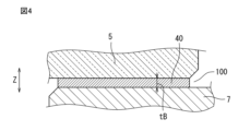
- FIG. 3 is a partial enlarged view of FIG. 2 for explaining a second member
- 11 is a graph showing the relationship between the thickness of the first member and the second member and the maximum displacement amount of the lens apex.
- 6 is a graph showing the relationship between the thickness of the first member and the second member and the maximum thermal stress applied to the lens.
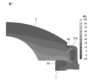
- 1 is a contour diagram showing thermal stress on a lens.
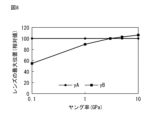
- FIG. 11 is a graph showing the relationship between the Young's modulus of the first member and the second member and the maximum displacement amount of the lens apex.
- 5 is a graph showing the relationship between the Young's modulus of the first member and the second member and the maximum thermal stress applied to the lens.
- FIG. 2 is a cross-sectional view showing a first modified example of the vibration device of FIG. 1 .
- FIG. 4 is a cross-sectional view showing a second modified example of the vibration device of FIG. 1 .
- FIG. 4 is a cross-sectional view showing a third modified example of the vibration device of FIG. 1 .
- FIG. 13 is a cross-sectional view showing a fourth modified example of the vibration device of FIG. FIG.
- FIG. 13 is a cross-sectional view showing a fifth modified example of the vibration device of FIG.
- FIG. 13 is a cross-sectional view showing a sixth modified example of the vibration device of FIG.
- FIG. 13 is a cross-sectional view showing a seventh modified example of the vibration device of FIG.
- FIG. 17 is a cross-sectional view taken along line XVII-XVII in FIG. 13 .
- FIG. 13 is a cross-sectional view showing an eighth modified example of the vibration device of FIG.
- the vibration device comprises: A vibrating body; a piezoelectric element located at one end of the vibrating body in a first direction; a light-transmitting body located at the other end of the vibrating body in the first direction; a pressing portion that sandwiches the light-transmitting body together with the other end of the vibration body in the first direction; a first member located between the light-transmitting body and the pressing portion and connected to the light-transmitting body and the pressing portion; a second member located between the light-transmitting body and the vibration body and connected to the light-transmitting body and the vibration body; The thickness of the first member is greater than or equal to the thickness of the second member.
- the first member and the second member act as a buffer layer that attenuates the thermal stress caused by the difference in the linear expansion coefficient of each of the translucent body, the vibrating body, and the pressing portion. This makes it possible to improve the bonding reliability between the translucent body and the vibrating body, as well as the bonding reliability between the translucent body and the pressing portion.
- a vibration device is the vibration device according to the first aspect,
- the Young's modulus of the first member is equal to or less than the Young's modulus of the second member.
- the vibration device of the second aspect can more reliably improve the reliability of the connection between the translucent body and the vibrating body, as well as the reliability of the connection between the translucent body and the pressing portion.
- a vibration device is the vibration device according to the first or second aspect,
- the second member includes a material having an adhesive function.
- the vibration device of the third aspect can more reliably suppress vibration damping of the vibration device.
- a vibration device is the vibration device according to any one of the first to third aspects,
- the first member includes a material having a waterproof function.
- the vibration device of the fourth aspect can more reliably prevent liquid droplets from entering the interior of the vibration device.
- the vibration device is A vibrating body; a piezoelectric element located at one end of the vibrating body in a first direction; a light-transmitting body located at the other end of the vibrating body in the first direction; a pressing portion that sandwiches the light-transmitting body together with the other end of the vibration body in the first direction; a first member located between the light-transmitting body and the pressing portion and connected to the light-transmitting body and the pressing portion; a second member located between the light-transmitting body and the vibration body and connected to the light-transmitting body and the vibration body;
- the Young's modulus of the first member is equal to or less than the Young's modulus of the second member.
- the first member and the second member act as a buffer layer that attenuates the thermal stress caused by the difference in the linear expansion coefficients of the translucent body, the vibrating body, and the pressing portion. This improves the reliability of the joint between the translucent body and the vibrating body, as well as the joint between the translucent body and the pressing portion.
- a vibration device is the vibration device according to the fifth aspect, The thickness of the first member is greater than or equal to the thickness of the second member.
- the vibration device of the sixth aspect can more reliably improve the reliability of the joint between the translucent body and the vibrating body, as well as the reliability of the joint between the translucent body and the pressing portion.
- a seventh aspect of the present disclosure provides a vibration device according to the fifth or sixth aspect of the present disclosure,
- the second member includes a material having an adhesive function.
- the seventh aspect of the vibration device makes it possible to more reliably suppress vibration damping of the vibration device.
- a vibration device is the vibration device according to any one of the fifth to seventh aspects,
- the first member includes a material having a waterproof function.
- the eighth aspect of the vibration device makes it possible to more reliably prevent liquid droplets from entering the interior of the vibration device.
- a vibration device is the vibration device according to any one of the first to eighth aspects,
- the device includes an external vibrator and a stopper portion.
- the external vibrator is a first connection portion provided with the pressing portion and connected to the light-transmitting body via the pressing portion; a second connection portion extending from the first connection portion in a direction away from the light-transmitting body along a direction intersecting the first direction; a fixing portion connected to an end portion of the second connection portion opposite to an end portion connected to the first connection portion, the fixing portion being connected to the end portion of the second connection portion in a direction intersecting the first direction;
- the stopper portion is connected to the fixed portion in a state in which the second connection portion can come into contact with the fixed portion, A first gap is provided between the stopper portion and the second connection portion in the first direction.
- the vibration device of the ninth aspect for example, when an external force is applied to the light-transmitting body toward the inside of the vibration device, the second connection portion comes into contact with the stopper portion, thereby preventing the light-transmitting body from colliding with a member located inside the vibration device. Also, for example, when stress is applied to the second connection portion, the second connection portion comes into contact with the stopper portion, thereby preventing excessive deformation of the second connection portion.
- a vibration device is the vibration device according to the ninth aspect, the stopper portion has an inclined surface facing the second connection portion in the first direction, The inclined surface inclines in a direction away from the second connection portion in the first direction as it approaches the first connection portion in a direction intersecting the first direction.
- the vibration device of the tenth aspect can more reliably prevent the translucent body from colliding with a component located inside the vibration device, and can more reliably prevent excessive deformation of the second connection portion.
- the vibration device of an eleventh aspect of the present disclosure is the vibration device of the ninth or tenth aspect,
- the fixing portion is configured to surround the vibration body around the optical axis of the light-transmitting body,
- the stopper portion has an annular shape extending in a circumferential direction with respect to the optical axis.
- the vibration device of the eleventh aspect can more reliably prevent the translucent body from colliding with a component located inside the vibration device, and can more reliably prevent excessive deformation of the second connection portion.
- a vibration device is the vibration device according to the ninth or tenth aspect,
- the fixing portion is configured to surround the vibration body around the optical axis of the light-transmitting body,
- the stopper portion includes a plurality of members spaced apart from one another along a circumferential direction relative to the optical axis.
- the vibration device of the twelfth aspect can more reliably prevent the translucent body from colliding with a component located inside the vibration device, and can more reliably prevent excessive deformation of the second connection portion.
- a vibration device is the vibration device according to any one of the ninth to twelfth aspects, The fixing portion and the stopper portion are integrally formed.
- the vibration device of the thirteenth aspect eliminates the need to connect the stopper portion to the fixed portion, thereby reducing the manufacturing costs of the vibration device.
- a vibration device is the vibration device according to any one of the ninth to thirteenth aspects, the fixing portion has a first opposing surface that faces the second connection portion with a gap therebetween in the first direction, The stopper portion is connected to the first opposing surface.
- the vibration device of the 14th aspect can more reliably prevent the translucent body from colliding with a component located inside the vibration device, and can more reliably prevent excessive deformation of the second connection portion.
- a vibration device is the vibration device according to any one of the ninth to thirteenth aspects, the fixed portion has a second opposing surface that faces the vibration body with a gap therebetween in a direction intersecting the first direction, The stopper portion is connected to the second opposing surface.
- the size of the first gap can be adjusted depending on the structure of the vibration device and the materials of each component that constitutes the vibration device.
- a vibration device is the vibration device according to any one of the ninth to fifteenth aspects, the stopper portion has a first layer and a second layer stacked in the first direction, The first layer is located closer to the second connection portion than the second layer, and is configured to have a smaller elastic modulus than the second layer.
- the vibration device of the 16th aspect reduces the deformation speed of the second connection part that comes into contact with the stopper part, making it possible to more reliably prevent excessive deformation of the second connection part. In addition, damage to the second connection part when it comes into contact with the stopper part can be prevented.
- a vibration device is the vibration device according to any one of the ninth to sixteenth aspects,
- the first gap has a size equal to or larger than the maximum amplitude of the light-transmitting body and smaller than the second gap.
- the vibration device of the 17th aspect can more reliably prevent the translucent body from colliding with a component located inside the vibration device, and can more reliably prevent excessive deformation of the second connection portion.
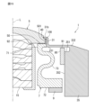
- the vibration device 1 includes a lens 5 (an example of a light-transmitting body), an internal vibration body (an example of a vibration body) 7, a piezoelectric element 9, a pressing portion 31b, a first member 40, and a second member 50.
- the lens 5 is made of glass, for example. As shown in FIG. 1, the upper surface of the lens 5 is convex, and the surface is coated with a water-repellent coating and an anti-reflection film (AR coating). A protrusion 501 extending radially outward is provided at the radial outer end of the lens 5. The upper surface 502 (see FIG. 3) of the protrusion 501 is curved along the curved surface 317 of the pressing portion 31b, which will be described later.
- AR coating anti-reflection film
- the internal vibrator 7 has a cylindrical body, for example, and amplifies the vibration from the piezoelectric element 9 to vibrate the lens 5.
- the internal vibrator 7 is composed of a first part 71 that contacts the lens 5, a second part 72 to which the piezoelectric element 9 is attached, and a third part 73 that connects the first part 71 and the second part 72 and has a cross-sectional shape of an approximately S-shape.
- the first part 71 has a cylindrical shape that is elongated in the axial direction of the cylindrical body (for example, the first direction Z).
- the first part 71 extends in the radial direction of the cylindrical body and is connected to the external vibrator 3.
- the second part 72 is a part that vibrates together with the vibration of the piezoelectric element 9, and has a plate thickness larger than that of the first part 71 and the third part 73. This makes it easier to transmit the vibration of the piezoelectric element 9 to the lens 5 more efficiently.
- the third part 73 is a part that supports the first part 71 and transmits the vibration of the second part 72 to the first part 71.
- the third portion 73 constitutes one end of the internal vibrator 7 in the first direction Z, and the first portion 71 constitutes the other end of the internal vibrator 7 in the first direction Z.
- the piezoelectric element 9 includes a piezoelectric body and an electrode.
- the piezoelectric body includes, for example, piezoelectric ceramics such as barium titanate (BaTiO3), lead zirconate titanate (PZT: PbTiO3.PbZrO3), lead titanate (PbTiO3), lead metaniobate (PbNb2O6), bismuth titanate (Bi4Ti3O12), (K,Na)NbO3, or piezoelectric single crystals such as LiTaO3 and LiNbO3.
- the electrode may be, for example, a Ni electrode.
- the electrode may be an electrode made of a metal thin film such as Ag or Au formed by a sputtering method. Alternatively, the electrode can be formed by plating or vapor deposition in addition to the sputtering method.
- the piezoelectric element 9 is connected to the second part 72 of the internal vibrator 7 by adhesive and is formed in a ring shape when viewed along the first direction Z, but this is not limited to this and any shape that can vibrate the internal vibrator 7 may be used.
- the pressing portion 31b constitutes a part of the external vibrator 3.
- the external vibrator 3 includes a first connection portion 31 and a second connection portion 33 in addition to the fixing portion 35.
- the pressing portion 31b is configured to be able to clamp the protrusion portion 501 of the lens 5 together with the first part 71 of the internal vibrator 7.
- the first connection portion 31 is located radially outside the first part 71 of the internal vibrator 7 and the lens 5, and extends from the second connection portion 33 toward the outside of the vibration device 1 along the first direction Z.
- the pressing portion 31b protrudes toward the lens 5 from the end of the first connection portion 31 farther from the second connection portion 33 in the first direction Z.
- the tip of the pressing portion 31b (i.e., the end facing the lens 5) is provided with a curved surface 317 (see FIG. 3) that protrudes toward the lens 5.
- the first connection portion 31 is provided with the pressing portion 31b.
- the first connection part 31 is connected to the lens 5 via the pressing part 31b.
- the second connection part 33 extends from the first connection part 31 in a direction (e.g., X direction) intersecting the first direction Z in a direction away from the lens 5.
- the second connection part 33 extends in a ring shape in a direction perpendicular to the optical axis direction (e.g., the first direction Z) of the lens 5 (in other words, in a radial direction with respect to the optical axis direction).
- the thickness of the second connection part 33 is smaller than the thickness of the fixing part 35, and is, for example, 0.2 mm to 1.0 mm.
- the thickness of the second connection part 33 is, for example, 0.2 times to 1.5 times that of the third part 73 of the internal vibrator 7. Since the second connection part 33 has such a thin thickness, it functions as a leaf spring.
- the second connection part 33 is configured to be elastically deformable along the first direction Z so as to absorb vibrations generated in the lens 5.
- the fixed part 35 is connected to the end 332 opposite to the end 331 connected to the first connection part 31, among both ends of the second connection part 33 in the direction intersecting the first direction Z.
- the fixed part 35 is connected to components such as a case (not shown) for storing an image sensor and a lens module 15 (see FIG. 13), and has a node that suppresses vibration to less than 1/100 of the displacement of the lens 5, and is configured not to transmit vibration to these components.
- the larger the volume of the fixed part 35 the more the vibration of the fixed part 35 can be suppressed.
- the fixed part 35 has a rectangular outer shape. If the outer shape is rectangular, the volume of the fixed part 35 can be increased without increasing the size of the vibration device 1. For example, a cube of 25 mm x 25 mm has a larger volume than a cylinder of 25 mm in diameter.
- an elastic body such as rubber or an adhesive layer is provided in the portion 100 surrounded by the lens 5, the first connection portion 31 of the external vibrator 3, and the first portion 71 of the internal vibrator 7. This reduces the load on the lens 5.
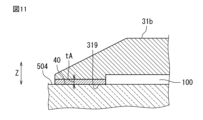
- the first member 40 is located between the lens 5 and the pressing portion 31b and is connected to the lens 5 and the pressing portion 31b.
- the second member 50 is located between the lens 5 and the internal vibrator 7 and is connected to the lens 5 and the internal vibrator 7.
- the first member 40 and the second member 50 include any material such as resin, metal, etc., and are configured to satisfy at least one of the following two conditions.
- the thickness tA of the first member 40 is greater than or equal to the thickness tB of the second member 50 (tA ⁇ tB).
- the Young's modulus yA of the first member 40 is equal to or less than the Young's modulus yB of the second member 50 (yA ⁇ yB).
- the thickness tA of the first member 40 is defined at the point where the thickness of the first member 40 is at its smallest.
- the thickness tB of the second member 50 is approximately uniform due to the flatness of the bonding surfaces of the lens 5 and the internal vibrator 7, so it may be defined at any point of the second member 50.
- the thicknesses tA and tB of the first member 40 and the second member 50 can be controlled by the viscosity of the adhesive, the amount of pressure applied when the adhesive hardens, the diameter of the spacer added to the adhesive, etc.
- the thicknesses tA and tB of the first member 40 and the second member 50 can be confirmed, for example, by observing the cross section of the vibration device 1 with a microscope.
- the key is to amplify the minute breathing vibration of the piezoelectric element 9 by the internal vibrator 7 and the pressing part 31b, etc., and transmit the vibration to the lens 5.
- the first member 40 and the second member 50 mainly have two roles: “transmitting vibration” and “strengthening the joint reliability between different materials.” In “transmitting vibration,” since the Young's modulus of the first member 40 and the second member 50 is small, it is advantageous for the first member 40 and the second member 50 to be thin.
- FIG. 5 is a graph showing the relationship between the thicknesses tA and tB of the first member 40 and the second member 50 and the maximum displacement of the apex of the lens 5, calculated using FEM (finite element method).
- FEM finite element method
- the thickness of one of the first member 40 and the second member 50 was changed, the thickness of the other of the first member 40 and the second member 50 was fixed at 0.005 mm.
- the sensitivity of the displacement of the top of the lens 5 to the thickness of the first member 40 and the second member 50 was greater for the second member 50 (tB), and the displacement of the top of the lens 5 attenuated as the second member 50 became thicker. This is for the following reason.
- the epoxy resin which is the material of the first member 40 and the second member 50, is a material with a relatively small Young's modulus, so it has the effect of attenuating vibration by deformation.
- the thicknesses tA and tB of the first member 40 and the second member 50 have different effects.
- the greater the difference in the linear expansion coefficients specific to the members the greater the thermal stress applied to the joint between the different materials, which causes peeling of the first member 40 and the second member 50, member destruction, etc.
- the linear expansion coefficient of the lens 5 glass
- the linear expansion coefficient of the pressing portion 31b stainless steel
- the thermal stress applied to each member of the lens 5, the internal vibrator 7, and the pressing portion 31b will be greater.
- Figure 6 is a graph showing the relationship between the thicknesses tA and tB of the first member 40 and the second member 50 and the maximum thermal stress applied to the lens 5 using FEM.
- the physical constants used in the FEM calculation results are as shown in Table 1 above.
- the thickness of the other of the first member 40 and the second member 50 was fixed at 0.005 mm.
- Figure 8 is a graph showing the relationship between the Young's moduli yA and yB of the first member 40 and the second member 50 using FEM and the maximum displacement of the apex of the lens 5.
- the physical constants used in the FEM calculation results are as shown in Table 1 above.
- the Young's modulus of one of the first member 40 and the second member 50 was changed, the Young's modulus of the other of the first member 40 and the second member 50 was fixed at 3 GPa.
- the sensitivity of the displacement of the apex of the lens 5 to the Young's moduli yA and yB of the first member 40 and the second member 50 was greater for the second member 50 (yB), and that the displacement of the apex of the lens 5 increased with an increase in the Young's modulus.
- the first member 40 (yA) has almost no sensitivity of the displacement of the apex of the lens 5 to the variation in the Young's modulus.
- Figure 9 is a graph showing the relationship between the Young's moduli yA and yB of the first member 40 and the second member 50 using FEM, and the maximum thermal stress applied to the lens 5.
- the physical constants used in the FEM calculation results are as shown in Table 1 above.
- the Young's modulus of one of the first member 40 and the second member 50 was changed, the Young's modulus of the other of the first member 40 and the second member 50 was fixed at 3 GPa.
- the second member 50 (yB) had almost no sensitivity of the thermal stress to the Young's modulus.
- the effective relationship between yA and yB is "yA ⁇ yB" from the standpoint of "vibration transmission” and "strengthening joint reliability between dissimilar materials.” This relationship holds regardless of the type of material used for the first member 40 and the second member 50. In other words, the first member 40 and the second member 50 may be made of the same material or different materials.
- the vibration device 1 of the present disclosure includes an internal vibrator 7, a piezoelectric element 9 located at one end of the internal vibrator 7 in the first direction, a lens 5 located at the other end of the internal vibrator 7 in the first direction, a pressing portion 31b that sandwiches the lens 5 together with the other end of the internal vibrator 7 in the first direction, and a first member 40 and a second member 50.
- the first member 40 is located between the lens 5 and the pressing portion 31b and is connected to the lens 5 and the pressing portion 31b.
- the second member 50 is located between the lens 5 and the internal vibrator 7 and is connected to the lens 5 and the internal vibrator 7.
- the first member 40 and the second member 50 are configured to satisfy at least one of the following conditions.
- the thickness tA of the first member 40 is equal to or greater than the thickness tB of the second member 50 (tA ⁇ tB).
- the Young's modulus yA of the first member 40 is equal to or less than the Young's modulus yB of the second member 50 (yA ⁇ yB).
- the vibration device 1 can also be configured as follows:
- the first member 40 may include a material having a waterproof function. This can more reliably prevent liquid droplets from penetrating into the inside of the vibration device 1.
- the material having a waterproof function includes, for example, a material that meets the IPX9K standard of the IP test based on the in-vehicle and automobile parts standard ISO20653.
- the second member 50 may contain a material with an adhesive function. This ensures the vibration characteristics of the vibration device 1, and more reliably suppresses vibration damping of the vibration device 1.
- the material with an adhesive function includes, for example, an adhesive whose tensile strength between the lens 5 and the internal vibrating body 7 is equal to or greater than the shear stress value or Z-normal stress value applied when the vibration device 1 is driven.
- the shapes of the lens 5 and the pressing portion 31b are not limited to those of the above embodiment.
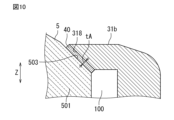
- a linearly extending inclined surface 318 may be provided at the tip of the pressing portion 31b, and an inclined surface 503 facing the inclined surface 318 may be provided on the upper surface of the protrusion 501 of the lens 5.
- a flat upper surface 504 may be provided on the lens 5, and a pressing surface 319 facing the upper surface 504 of the lens 5 may be provided at the tip of the pressing portion 31b.
- the pressing portion is not limited to pressing portion 31b constituting a part of the vibrating body (external vibrating body 3 in the above embodiment).
- it may be constituted by a member (also called pressing member) 60 separate from the vibrating body.
- the pressing member 60 includes, for example, a cylindrical side wall 62 and a pressing portion 61 that protrudes inward (for example, in the X direction and in the direction approaching the lens 5) in the radial direction (hereinafter referred to as the radial direction) relative to the optical axis of the side wall 62.
- the vibrating body 120 includes, for example, a cylindrical main body portion 121 and a support portion 122 that protrudes inward in the radial direction from the main body portion 121.
- the vibration device 1 may include a stopper portion 80, as shown in Figs. 13 to 16.
- the stopper portion 80 is connected to the fixed portion 35 in a state in which the second connection portion 33 can come into contact with the stopper portion 80.
- a first gap 91 is provided between the stopper portion 80 and the second connection portion 33 in the first direction Z.
- the stopper portion 80 may be made of any material, including metal and resin.
- the fixing portion 35 has a first opposing surface 351 that faces the second connection portion 33 at a distance in the first direction Z.
- the stopper portion 80 is connected to the first opposing surface 351 of the fixing portion 35.
- the stopper portion 80 is a separate member from the fixing portion 35, and is fixed to the fixing portion 35 with an adhesive or the like.
- the second connection portion 33 is composed of a first leaf spring portion 3301, a second leaf spring portion 3302, and a linking portion 3303.
- the first leaf spring portion 3301 extends radially outward from the end 331 connected to the first connection portion 31.
- the fixing portion 35 is located between the first leaf spring portion 3301 and the first opposing surface 351.
- the second leaf spring portion 3302 extends from the end farther from the first connection portion 31 of both ends of the first leaf spring portion 3301 in the radial direction toward the fixing portion 35 along the first direction Z.
- a third gap 93 is provided between the fixing portion 35 and the second leaf spring portion 3302. The third gap 93 does not have to be provided.
- the linking portion 3303 extends radially outward from the end closer to the fixing portion 35 of both ends of the second leaf spring portion 3302 in the first direction Z along the first opposing surface 351.
- the radially outer end of the connecting portion 3303 constitutes the end portion 332.
- the second connection portion 33 is connected to the fixed portion 35 via the connecting portion 3303.
- the second connection part 33 moves toward the inside of the vibration device 1 via the first connection part 31 connected to the lens 5 and comes into contact with the stopper part 80.
- the stopper part 80 it is possible to prevent the lens 5 from colliding with a member (e.g., the lens module 15) located inside the vibration device 1.
- the second connection part 33 comes into contact with the stopper part 80, and therefore excessive deformation of the second connection part 33 can be prevented.
- the stopper portion 80 is connected to the first opposing surface 351 of the fixing portion 35, so that collision of the lens 5 with a component (e.g., the lens module 15) located inside the vibration device 1 can be more reliably prevented, and excessive deformation of the second connection portion 33 can be more reliably prevented.
- a component e.g., the lens module 15
- the first gap 91 has a size, for example, equal to or greater than the maximum amplitude of the lens 5 and less than the second gap 92. This configuration can more reliably prevent the lens 5 from colliding with a component (for example, the lens module 15) located inside the vibration device 1, and can more reliably prevent excessive deformation of the second connection portion 33.
- the second gap 92 is, for example, the smallest gap between the lens 5 and the lens module 15 in the first direction Z.
- the fixing portion 35 and the stopper portion 80 are integrally configured. By integrally configuring the fixing portion 35 and the stopper portion 80, it is no longer necessary to connect the stopper portion 80 to the fixing portion 35, and therefore the manufacturing cost of the vibration device 1 can be reduced.
- the stopper portion 80 has an inclined surface 81 facing the second connection portion 33 in the first direction Z.
- the inclined surface 81 is inclined in the first direction Z in a direction intersecting the first direction Z (e.g., the X direction) as it approaches the first connection portion 31.
- the area in which the stopper portion 80 and the first leaf spring portion 3301 of the second connection portion 33 can contact each other can be made larger than in a vibration device 1 in which the stopper portion 80 does not have an inclined surface 81.
- collision of the lens 5 with a member (e.g., the lens module 15) located inside the vibration device 1 can be more reliably prevented, and excessive deformation of the second connection portion 33 can be more reliably prevented.
- the fixing portion 35 has a second opposing surface 352 that faces the internal vibrator 7 at a distance in a direction (e.g., the X direction) intersecting the first direction Z.
- the stopper portion 80 is connected to the second opposing surface 352 of the fixing portion 35.
- the stopper portion 80 is a separate member from the fixing portion 35, and is fixed to the fixing portion 35 by adhesive or the like.
- the stopper portion 80 has a first layer 801 and a second layer 802 stacked in the first direction Z.
- the first layer 801 is located closer to the second connection portion 33 than the second layer 802.
- a first gap 91 is formed between the first layer 801 and the first leaf spring portion 3301.
- the first layer 801 is configured to have a smaller elastic modulus than the second layer 802.
- the stopper portion 80 can be configured to have an annular shape extending in the circumferential direction relative to the optical axis L of the lens 5, as shown in FIG. 17, for example.
- the fixing portion 35 is configured to surround the internal vibrator 7 around the optical axis L.
- the stopper portion 80 is not limited to having an annular shape, and may be configured to include a plurality of members 82 positioned at intervals along the circumferential direction relative to the optical axis L, as shown in FIG. 18, for example. All of the plurality of members 82, or some of the plurality of members 82, may have substantially the same shape and size. All of the plurality of members 82 may have mutually different shapes and sizes.
Landscapes
- Physics & Mathematics (AREA)
- General Physics & Mathematics (AREA)
- Optics & Photonics (AREA)
- Engineering & Computer Science (AREA)
- Multimedia (AREA)
- Signal Processing (AREA)
- Lens Barrels (AREA)
- Apparatuses For Generation Of Mechanical Vibrations (AREA)
Priority Applications (3)
| Application Number | Priority Date | Filing Date | Title |
|---|---|---|---|
| JP2024549091A JPWO2024070063A1 (https=) | 2022-09-28 | 2023-06-06 | |
| CN202380065813.6A CN119866465A (zh) | 2022-09-28 | 2023-06-06 | 振动装置 |
| US19/052,378 US20250189781A1 (en) | 2022-09-28 | 2025-02-13 | Vibration device |
Applications Claiming Priority (2)
| Application Number | Priority Date | Filing Date | Title |
|---|---|---|---|
| JP2022-155068 | 2022-09-28 | ||
| JP2022155068 | 2022-09-28 |
Related Child Applications (1)
| Application Number | Title | Priority Date | Filing Date |
|---|---|---|---|
| US19/052,378 Continuation US20250189781A1 (en) | 2022-09-28 | 2025-02-13 | Vibration device |
Publications (1)
| Publication Number | Publication Date |
|---|---|
| WO2024070063A1 true WO2024070063A1 (ja) | 2024-04-04 |
Family
ID=90476832
Family Applications (1)
| Application Number | Title | Priority Date | Filing Date |
|---|---|---|---|
| PCT/JP2023/021009 Ceased WO2024070063A1 (ja) | 2022-09-28 | 2023-06-06 | 振動装置 |
Country Status (4)
| Country | Link |
|---|---|
| US (1) | US20250189781A1 (https=) |
| JP (1) | JPWO2024070063A1 (https=) |
| CN (1) | CN119866465A (https=) |
| WO (1) | WO2024070063A1 (https=) |
Citations (2)
| Publication number | Priority date | Publication date | Assignee | Title |
|---|---|---|---|---|
| WO2021210208A1 (ja) * | 2020-04-17 | 2021-10-21 | 株式会社村田製作所 | 振動装置 |
| JP7099633B2 (ja) * | 2020-05-15 | 2022-07-12 | 株式会社村田製作所 | 振動装置 |
-
2023
- 2023-06-06 JP JP2024549091A patent/JPWO2024070063A1/ja active Pending
- 2023-06-06 WO PCT/JP2023/021009 patent/WO2024070063A1/ja not_active Ceased
- 2023-06-06 CN CN202380065813.6A patent/CN119866465A/zh active Pending
-
2025
- 2025-02-13 US US19/052,378 patent/US20250189781A1/en active Pending
Patent Citations (2)
| Publication number | Priority date | Publication date | Assignee | Title |
|---|---|---|---|---|
| WO2021210208A1 (ja) * | 2020-04-17 | 2021-10-21 | 株式会社村田製作所 | 振動装置 |
| JP7099633B2 (ja) * | 2020-05-15 | 2022-07-12 | 株式会社村田製作所 | 振動装置 |
Also Published As
| Publication number | Publication date |
|---|---|
| CN119866465A (zh) | 2025-04-22 |
| US20250189781A1 (en) | 2025-06-12 |
| JPWO2024070063A1 (https=) | 2024-04-04 |
Similar Documents
| Publication | Publication Date | Title |
|---|---|---|
| Wang et al. | Electromechanical coupling and output efficiency of piezoelectric bending actuators | |
| US12477199B2 (en) | Vibration device and imaging device | |
| JP2000081504A (ja) | 可変焦点レンズ | |
| JP6837135B2 (ja) | 軸方向変位の圧電アクチュエータ、水中音響トランスデューサ及び軸方向変位の圧電アクチュエータの製造方法 | |
| JP7099633B2 (ja) | 振動装置 | |
| JP5556967B2 (ja) | 圧電アクチュエータ | |
| JP6643288B2 (ja) | 振動波モータ及び振動波モータを有したレンズ駆動装置 | |
| WO2001026167A1 (en) | Piezoelectric / electrostrictive device and method of manufacture thereof | |
| CN110114968A (zh) | 用于振动波电机的压电振动器 | |
| AU2017318083B2 (en) | Piezoelectric actuator and low frequency underwater projector | |
| JP5316756B2 (ja) | 駆動装置 | |
| CN106059384A (zh) | 振动波马达 | |
| WO2024070063A1 (ja) | 振動装置 | |
| WO2020136994A1 (ja) | 圧電トランスデューサ | |
| KR101601871B1 (ko) | 변위 부재, 구동 부재, 액츄에이터 및 구동 장치 | |
| JP5440161B2 (ja) | 圧電振動デバイス | |
| WO2025088832A1 (ja) | 振動装置および内部振動体 | |
| WO2020136983A1 (ja) | 圧電トランスデューサ | |
| WO2024252708A1 (ja) | 振動装置 | |
| WO2014174750A1 (ja) | 駆動装置およびこれを用いた撮像装置 | |
| US20130320810A1 (en) | Piezoelectric Vibrating Component | |
| WO2025052705A1 (ja) | 振動装置 | |
| WO2022107566A1 (ja) | 振動装置 | |
| US20250355320A1 (en) | Optical device and imaging unit including optical device | |
| Gaucher | Piezoelectric micro-electro-mechanical systems for acoustic applications |
Legal Events
| Date | Code | Title | Description |
|---|---|---|---|
| 121 | Ep: the epo has been informed by wipo that ep was designated in this application |
Ref document number: 23871308 Country of ref document: EP Kind code of ref document: A1 |
|
| WWE | Wipo information: entry into national phase |
Ref document number: 2024549091 Country of ref document: JP |
|
| WWE | Wipo information: entry into national phase |
Ref document number: 202380065813.6 Country of ref document: CN |
|
| WWP | Wipo information: published in national office |
Ref document number: 202380065813.6 Country of ref document: CN |
|
| NENP | Non-entry into the national phase |
Ref country code: DE |
|
| 122 | Ep: pct application non-entry in european phase |
Ref document number: 23871308 Country of ref document: EP Kind code of ref document: A1 |