WO2024069795A1 - 治療器具およびスクリュー - Google Patents
治療器具およびスクリュー Download PDFInfo
- Publication number
- WO2024069795A1 WO2024069795A1 PCT/JP2022/036147 JP2022036147W WO2024069795A1 WO 2024069795 A1 WO2024069795 A1 WO 2024069795A1 JP 2022036147 W JP2022036147 W JP 2022036147W WO 2024069795 A1 WO2024069795 A1 WO 2024069795A1
- Authority
- WO
- WIPO (PCT)
- Prior art keywords
- screw
- driver
- thread
- tip
- inner cylinder
- Prior art date
- Legal status (The legal status is an assumption and is not a legal conclusion. Google has not performed a legal analysis and makes no representation as to the accuracy of the status listed.)
- Ceased
Links
Images




Classifications
-
- A—HUMAN NECESSITIES
- A61—MEDICAL OR VETERINARY SCIENCE; HYGIENE
- A61B—DIAGNOSIS; SURGERY; IDENTIFICATION
- A61B17/00—Surgical instruments, devices or methods
- A61B17/56—Surgical instruments or methods for treatment of bones or joints; Devices specially adapted therefor
- A61B17/58—Surgical instruments or methods for treatment of bones or joints; Devices specially adapted therefor for osteosynthesis, e.g. bone plates, screws or setting implements
- A61B17/68—Internal fixation devices, including fasteners and spinal fixators, even if a part thereof projects from the skin
- A61B17/70—Spinal positioners or stabilisers, e.g. stabilisers comprising fluid filler in an implant
- A61B17/7097—Stabilisers comprising fluid filler in an implant, e.g. balloon; devices for inserting or filling such implants
- A61B17/7098—Stabilisers comprising fluid filler in an implant, e.g. balloon; devices for inserting or filling such implants wherein the implant is permeable or has openings, e.g. fenestrated screw
-
- A—HUMAN NECESSITIES
- A61—MEDICAL OR VETERINARY SCIENCE; HYGIENE
- A61B—DIAGNOSIS; SURGERY; IDENTIFICATION
- A61B17/00—Surgical instruments, devices or methods
- A61B17/56—Surgical instruments or methods for treatment of bones or joints; Devices specially adapted therefor
- A61B17/58—Surgical instruments or methods for treatment of bones or joints; Devices specially adapted therefor for osteosynthesis, e.g. bone plates, screws or setting implements
- A61B17/68—Internal fixation devices, including fasteners and spinal fixators, even if a part thereof projects from the skin
- A61B17/84—Fasteners therefor or fasteners being internal fixation devices
- A61B17/86—Pins or screws or threaded wires; nuts therefor
-
- A—HUMAN NECESSITIES
- A61—MEDICAL OR VETERINARY SCIENCE; HYGIENE
- A61B—DIAGNOSIS; SURGERY; IDENTIFICATION
- A61B17/00—Surgical instruments, devices or methods
- A61B17/56—Surgical instruments or methods for treatment of bones or joints; Devices specially adapted therefor
- A61B17/58—Surgical instruments or methods for treatment of bones or joints; Devices specially adapted therefor for osteosynthesis, e.g. bone plates, screws or setting implements
- A61B17/68—Internal fixation devices, including fasteners and spinal fixators, even if a part thereof projects from the skin
- A61B17/84—Fasteners therefor or fasteners being internal fixation devices
- A61B17/86—Pins or screws or threaded wires; nuts therefor
- A61B17/8625—Shanks, i.e. parts contacting bone tissue
- A61B17/8635—Tips of screws
-
- A—HUMAN NECESSITIES
- A61—MEDICAL OR VETERINARY SCIENCE; HYGIENE
- A61B—DIAGNOSIS; SURGERY; IDENTIFICATION
- A61B17/00—Surgical instruments, devices or methods
- A61B17/56—Surgical instruments or methods for treatment of bones or joints; Devices specially adapted therefor
- A61B17/58—Surgical instruments or methods for treatment of bones or joints; Devices specially adapted therefor for osteosynthesis, e.g. bone plates, screws or setting implements
- A61B17/68—Internal fixation devices, including fasteners and spinal fixators, even if a part thereof projects from the skin
- A61B17/84—Fasteners therefor or fasteners being internal fixation devices
- A61B17/86—Pins or screws or threaded wires; nuts therefor
- A61B17/864—Pins or screws or threaded wires; nuts therefor hollow, e.g. with socket or cannulated
-
- A—HUMAN NECESSITIES
- A61—MEDICAL OR VETERINARY SCIENCE; HYGIENE
- A61B—DIAGNOSIS; SURGERY; IDENTIFICATION
- A61B17/00—Surgical instruments, devices or methods
- A61B17/56—Surgical instruments or methods for treatment of bones or joints; Devices specially adapted therefor
- A61B17/58—Surgical instruments or methods for treatment of bones or joints; Devices specially adapted therefor for osteosynthesis, e.g. bone plates, screws or setting implements
- A61B17/68—Internal fixation devices, including fasteners and spinal fixators, even if a part thereof projects from the skin
- A61B17/84—Fasteners therefor or fasteners being internal fixation devices
- A61B17/86—Pins or screws or threaded wires; nuts therefor
- A61B17/8685—Pins or screws or threaded wires; nuts therefor comprising multiple separate parts
-
- A—HUMAN NECESSITIES
- A61—MEDICAL OR VETERINARY SCIENCE; HYGIENE
- A61B—DIAGNOSIS; SURGERY; IDENTIFICATION
- A61B17/00—Surgical instruments, devices or methods
- A61B17/56—Surgical instruments or methods for treatment of bones or joints; Devices specially adapted therefor
- A61B17/58—Surgical instruments or methods for treatment of bones or joints; Devices specially adapted therefor for osteosynthesis, e.g. bone plates, screws or setting implements
- A61B17/88—Osteosynthesis instruments; Methods or means for implanting or extracting internal or external fixation devices
-
- A—HUMAN NECESSITIES
- A61—MEDICAL OR VETERINARY SCIENCE; HYGIENE
- A61B—DIAGNOSIS; SURGERY; IDENTIFICATION
- A61B17/00—Surgical instruments, devices or methods
- A61B17/56—Surgical instruments or methods for treatment of bones or joints; Devices specially adapted therefor
- A61B17/58—Surgical instruments or methods for treatment of bones or joints; Devices specially adapted therefor for osteosynthesis, e.g. bone plates, screws or setting implements
- A61B17/88—Osteosynthesis instruments; Methods or means for implanting or extracting internal or external fixation devices
- A61B17/8802—Equipment for handling bone cement or other fluid fillers
- A61B17/8805—Equipment for handling bone cement or other fluid fillers for introducing fluid filler into bone or extracting it
- A61B17/8811—Equipment for handling bone cement or other fluid fillers for introducing fluid filler into bone or extracting it characterised by the introducer tip, i.e. the part inserted into or onto the bone
-
- A—HUMAN NECESSITIES
- A61—MEDICAL OR VETERINARY SCIENCE; HYGIENE
- A61B—DIAGNOSIS; SURGERY; IDENTIFICATION
- A61B17/00—Surgical instruments, devices or methods
- A61B17/56—Surgical instruments or methods for treatment of bones or joints; Devices specially adapted therefor
- A61B17/58—Surgical instruments or methods for treatment of bones or joints; Devices specially adapted therefor for osteosynthesis, e.g. bone plates, screws or setting implements
- A61B17/88—Osteosynthesis instruments; Methods or means for implanting or extracting internal or external fixation devices
- A61B17/8875—Screwdrivers, spanners or wrenches
-
- A—HUMAN NECESSITIES
- A61—MEDICAL OR VETERINARY SCIENCE; HYGIENE
- A61B—DIAGNOSIS; SURGERY; IDENTIFICATION
- A61B17/00—Surgical instruments, devices or methods
- A61B17/56—Surgical instruments or methods for treatment of bones or joints; Devices specially adapted therefor
- A61B17/58—Surgical instruments or methods for treatment of bones or joints; Devices specially adapted therefor for osteosynthesis, e.g. bone plates, screws or setting implements
- A61B17/88—Osteosynthesis instruments; Methods or means for implanting or extracting internal or external fixation devices
- A61B17/8875—Screwdrivers, spanners or wrenches
- A61B17/8886—Screwdrivers, spanners or wrenches holding the screw head
- A61B17/8888—Screwdrivers, spanners or wrenches holding the screw head at its central region
Definitions
- the present invention relates to a treatment instrument and screw, and is particularly suitable for use in surgery in which cement is first filled inside the affected bone and then a screw is screwed into the cement from the outside of the bone.
- the spine consists of stacked vertebral bodies, the vertebral arch that supports and connects them vertically, the pedicle, the upper and lower articular processes, etc.
- the vertebral body is a cylindrical bone that sandwiches the nucleus pulposus and the annulus fibrosus that surrounds it from above and below, and is supported by two pedicles extending from the vertebral arch.
- the vertebral arch is connected from above to below by the upper and lower articular processes, supports the vertebral body via the pedicle, and forms the spine.
- Compression fracture is a disease in which the vertebral body is crushed and damaged by vertical compression.
- Vertebroplasty is a surgery to reconstruct the crushed vertebral body, and for example, a surgical procedure is used to fill the vertebral body with medical cement.
- Spinal fusion is a surgical procedure to fix the affected intervertebral space for degenerative spinal diseases, and a surgical procedure to fix the healthy vertebral bodies above and below with instruments for compression fractures.
- Artificial disc replacement is a surgical procedure in which an artificial disc is inserted between affected vertebrae.
- spinal fusion screws are screwed into the pedicles of multiple vertebrae, and the heads of the screws are connected to rods that run vertically between each other to fix the affected vertebrae or fractured vertebrae.
- spinal fusion, artificial disc replacement, or vertebroplasty are appropriately selected or combined for each disease.
- Patent document 1 discloses a screwdriver for driving a screw from the pedicle to the vertebral body.
- the screwdriver is composed of a shank for rotating the pedicle screw, a clamping sleeve that supports the shank so that it can rotate around it, and an adapter sleeve that is attached to the clamping sleeve and transmits rotation from the handle.
- the adapter sleeve is removable, and when removed, the shank and clamping sleeve connected to the pedicle screw remain, which is said to improve the surgeon's view of the treatment site (paragraphs 0014 to 0015).
- Patent document 2 discloses a medical device for spinal fixation that interconnects spinal rods with the patient's vertebrae. Bone anchors (bone screws) implanted in the vertebrae are connected to rods that run along the spine using various components.
- Patent Document 3 discloses a medical screw that can be easily removed from the fracture site once it has been screwed in.
- This medical screw is hollow along the central axis from the head, has a threaded portion on the outside, and further inside, near the hollow tip, has a reverse internal thread that runs in the opposite direction to the threaded portion.
- a hex wrench Figure 3
- a removal tool Figure 7
- Figure 7 Figure 7
- Vertebroplasty is performed percutaneously, which reduces invasiveness and reduces the burden on patients, thereby contributing to shortening hospital stays and reducing medical and nursing care costs. While percutaneous vertebroplasty has shown good results in many cases, complications such as dislodging of the filled cement have been reported.
- the inventors have discovered a problem in that there has been insufficient development of medical instruments and screws suitable for combined surgical procedures involving artificial disc replacement, spinal fixation, vertebroplasty, and pedicle plasty for spinal diseases associated with osteoporosis as described above.
- the screwdriver shown in Patent Document 1 also functions as a cement injection cannula, and is said to be able to inject cement into the pedicle screw via the shank without changing the instrument (paragraphs 0058 to 0068).
- cement can be injected into the pedicle screw 30 into which the cannula is inserted via the shank 2 without changing the instrument" (paragraph 0068)
- bone cement is injected into a cannulated bone anchor using an injection assembly shown in FIG. 9A.
- the cannula of the injection assembly is tightly sealed to the head of the bone anchor by the structure shown in FIG. 9B, thereby preventing the bone cement from leaking into the connection portion (paragraph 0054).
- this document also does not anticipate screwing the screw into the cement mass after injecting the cement, as it states that "the bone screw 22 is further cannulated and fenestrated (not shown) with openings extending outward from a central hollow passage in the cannulated screw to push fluid out of the screw during insertion or to draw fluid from the side of the screw into the central hollow passage during extraction of material adjacent to the screw" (paragraph 0017).
- instruments such as drivers used to screw in the screws also function as cannulas to pass the cement through, which means that it is a heavy burden to wash off the cement after use. In many cases, the instruments used to pass the cement are prohibited from being reused and are considered disposable.
- the screw into which the cement is injected has an opening on the side through which the cement is discharged (see paragraph 0017 of Patent Document 2 cited above).
- This is another means of filling the area around the screw with cement, instead of screwing the screw into the cement mass after the cement is injected, and many medical devices other than those in Patent Document 2 are designed based on this method.
- the side hole is small, it needs to be filled at high pressure, and the cement is filled without securing a space for filling it.
- the present inventor who is an orthopedic surgeon, has also found another problem. Whether the screw is screwed into the cement mass after cement injection or the cement is discharged from the side outlet after the screw is screwed in to reinforce the connection between the screw and the surrounding bone, the possibility of the need to remove the screw in the future is not fully considered. In fact, there have been no cases of symptoms requiring screw removal in a procedure that combines vertebroplasty and pedicle plasty. However, in general, it is possible that the screw may need to be removed if a bacterial infection occurs in the vertebra into which the screw was inserted, or if symptoms of the inserted screw accidentally irritating a nerve are discovered at a later date. In addition, if symptoms worsen at a later date and it becomes necessary to perform multi-level spinal fixation surgery, it is necessary to replace the screw with one that can be connected to a rod for spinal fixation, so it is necessary to consider even the removal of the screw.
- the screw will be difficult to remove if it is reinforced with cement. If the screw is screwed into a cement block before it has fully hardened, it will be very difficult to remove after it has hardened. Also, if cement is injected through the outlet on the side wall of the screw, the cement remaining in the screw cavity and the cement on the outside will harden while still connected by the outlet, preventing the screw from rotating. This is because to remove the screw, the cement at the outlet must be destroyed by rotating the screw.
- none of the current medical devices are fully suitable for the above-mentioned procedures that combine vertebroplasty and pedicle plasty, as well as spinal fixation for degenerative spinal disease and fractures due to osteoporosis, vertebral reinforcement surgery during artificial disc replacement, vertebroplasty, and pedicle plasty.
- the object of the present invention is to provide a treatment instrument and screw suitable for spinal fixation surgery for osteoporotic spinal degenerative disease and fractures, vertebral reinforcement surgery during artificial disc replacement surgery, vertebroplasty, and pedicle plasty.
- a further object of the present invention is to minimize the number of instruments used for cement filling and to reduce the burden of cleaning or disposable items to avoid cleaning, and a further object is to facilitate removal of the screw.
- a treatment instrument that includes a cylindrical driver that can screw a screw into bone, an inner tube that can be inserted into the driver, and a guide pin that can be inserted into the inner tube, and is configured as follows.
- the screw has threads on its outer wall (periphery) that can tap into bone, and a through hole that allows the inner tube to pass from the head to the tip along the central axis.
- the driver is configured so that it can be fitted into the head of the screw by moving it along the central axis, and when fitted, it can connect with the screw, and can transmit a rotational force around the central axis to the screw.
- the inner cylinder has a tip end that is inserted from the distal end of the driver through the through hole of the driver and the screw when the screw and the driver are connected, and protrudes proximally from the tip of the screw.
- the inner cylinder is connected to the screw by inserting a guide pin with the tip end protruding proximally from the tip of the screw.
- proximal is a medical term that refers to the side closer to the center line of the patient's body
- distal is a medical term that refers to the far side.
- the cement is a medical bone cement, for example, mainly composed of calcium phosphate and polymethylmethacrylate, and hardens over time.
- FIG. 1 is an explanatory diagram that shows a schematic cross-sectional structure to illustrate a configuration example of a treatment device according to a first embodiment of the present invention.
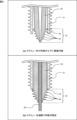
- FIG. 2 is an explanatory diagram showing an example of the configuration of the tip end of the inner cylinder from a bird's-eye view.
- FIG. 3 is an explanatory diagram showing a schematic cross-sectional structure to show an example of the configuration of the tip portion of the inner cylinder.
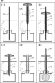
- FIG. 4 is an explanatory diagram that shows a schematic diagram of a treatment procedure (first half) using the treatment device of the present invention.
- FIG. 5 is an explanatory diagram that shows a schematic diagram of a treatment procedure (latter half) using the treatment device of the present invention.
- FIG. 1 is an explanatory diagram that shows a schematic cross-sectional structure to illustrate a configuration example of a treatment device according to a first embodiment of the present invention.
- FIG. 2 is an explanatory diagram showing an example of the configuration of the tip end of the inner cylinder
- FIG. 6 is an explanatory diagram that shows a schematic cross-sectional structure to illustrate an example of the configuration of a screw according to a second embodiment of the present invention.
- FIG. 7 is an explanatory diagram that shows a schematic cross-sectional structure to illustrate an example of the configuration of a screw according to a third embodiment of the present invention.
- FIG. 8 is an explanatory diagram showing a cross section of an example of a thread of a screw of the present invention.
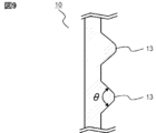
- FIG. 9 is an explanatory diagram showing a cross section of another example of the thread of the screw of the present invention.
- a treatment device that integrates a cylindrical driver and an inner cylinder by inserting a guide pin ( Figure 1)
- a representative embodiment disclosed in the present application is a treatment instrument (100) including a cylindrical driver (20) capable of screwing a screw (10) into bone, an inner tube (30) that can be inserted into the driver, and a guide pin (60) that can be inserted into the inner tube, and is configured as follows:
- the screw has a thread (13) that can be tapped into the outer wall, and a through hole that allows the inner tube to pass from the head (11) to the tip along the central axis.
- a thread that can be tapped refers to a thread that can be cut around the periphery in conjunction with the action of screwing the screw to form a thread groove that meshes with the thread.
- the driver is configured so that it can be fitted into the head of the screw and connected to the screw by moving it along the central axis, and can transmit a rotational force around the central axis to the screw.
- the inner cylinder is inserted from the distal end of the driver through the through holes of the driver and the screw when the screw and the driver are connected, and has a tip portion (32) that protrudes proximally beyond the tip of the screw.
- the inner tube is inserted from the distal end of the driver when the driver is connected to the screw, and can be connected to the driver at the distal end (35, 36, 25, 26), and when connected to the driver, the tip protrudes proximally beyond the tip of the screw.
- the inner tube is connected to the screw by inserting the guide pin with the tip protruding proximally beyond the tip of the screw.
- the tongues bend toward the central axis and can move in the central axis direction within the through holes of the driver and screw (upper part of Figure 3).
- the guide pin is inserted into the inner tube, restricting the tongues from bending in the central axis direction, and the protrusions come into contact with the tip of the screw, restricting the inner tube from moving back along the central axis toward the through hole of the screw (lower part of Figure 3).
- the protrusions protrude outward (away from the central axis) beyond the inner wall of the through hole of the screw, restricting the screw from slipping out of the inner tube.
- the inner tube has a thread (34) that can be tapped on the outer circumferential surface of the tip.
- Screw threads The number of threads decreases from distal to proximal ( Figure 7) In the treatment device (100) of [1] to [3], the number of threads of the screw is greater on the distal side and smaller on the proximal side.
- thread refers to the thread, and the number of threads is a number that indicates the number of threads of the same screw groove.
- the outer diameter of the screw threads is smaller toward the proximal end, and the number of threads decreases toward the proximal end ( Figure 7).
- the outer diameter of the screw thread is larger on the distal side and smaller on the proximal side, and the number of threads is greater on the distal side and less on the proximal side.
- This invention can also be considered an invention of the screw alone.
- Screw Smaller diameter threads on the proximal side ( Figure 6)
- An exemplary embodiment disclosed herein is a screw (10) with threads that can tap bone into an outer wall when screwed, the outer diameter of the threads being larger distally and smaller proximally.
- Screw The number of threads decreases from distal to proximal ( Figure 7)
- An exemplary embodiment disclosed herein is a screw (10) with threads that can tap bone into the outer wall when screwed, the threads having more distal and less proximal threads.
- Screw The outer diameter of the thread is smaller toward the proximal end, and the number of threads decreases toward the proximal end ( Figure 7).
- An exemplary embodiment disclosed herein is a screw (10) having threads that can tap bone into an outer wall when screwed, the outer diameter of the threads being larger distally and smaller proximally, and the number of threads being more distally and less proximally.
- FIG. 1 is an explanatory diagram showing a schematic cross-sectional structure to show a configuration example of a treatment device 100 according to a first embodiment of the present invention.
- Fig. 1 is drawn with the scale of the central axis direction (vertical direction on the page) compressed and with emphasis on the direction along the patient's body surface (horizontal direction on the page). The same is true for the other drawings.
- the treatment instrument 100 of the present invention includes a cylindrical driver 20 capable of screwing a screw 10 into a bone, an inner tube 30 inserted into the driver 20, and a guide pin 60 inserted into the inner tube 30, and is configured as follows.
- the tip of the screw 10 is blunt so that a soft vertebral excavation device such as a balloon can be inserted and removed, and has a thread 13 that can tap bone or cement on the outer wall, and a through hole that can pass the inner tube 30 from the head 11 to the tip along the central axis.
- the driver 20 is configured to fit into the head 11 of the screw 10 by moving along the central axis and connect to the screw 10, and to transmit a rotational force around the central axis to the screw 10.
- the tip of the driver 20 may be formed in the shape of a hexagonal wrench (hexagonal column), and the head 11 of the screw 10 may be formed with a hexagonal groove (recess).
- the shape of the driver tip and the shape of the screw head may be other than hexagonal, such as a star shape, as long as they are engaged simply by inserting them. If the driver 20 is slid into the head of the screw 10 along the central axis, the tip of the driver 20 fits into the head 11 of the screw 10, making it possible to screw the screw with the driver 10, and the driver 10 can be easily removed by pulling out the driver 10.
- the head structure of the screw may further include a structure (not shown) with a U-shaped passageway to allow a spinal fixation rod to be secured, if necessary.
- the inner tube 30 is inserted from the distal end of the driver 20 through the through holes of the driver 20 and the screw 10 when the screw 10 and the driver 20 are connected, and has a tip portion 32 that protrudes proximally beyond the tip of the screw 10.
- the inner tube 30 is connected to the screw 10 by inserting a guide pin 60 with the tip portion 32 protruding proximally beyond the tip of the screw 10.
- the driver 20 and the inner tube 30 are configured so that they can be connected at their distal ends.
- the distal end of the driver 20 is provided with a cylindrical connection part 25 having a male screw 26 thread on the outer circumferential surface
- the distal end of the inner tube 30 is provided with a groove-shaped connection part 35 that can accommodate the cylinder, and a female screw 36 that engages with the male screw 26 is formed.
- the relationship of the convex and concave parts and the relationship of the male screw and the female screw may be reversed, or other connection mechanisms may be used. Also, as exemplified in FIG.
- the driver 20 is provided with a handle 27 and the inner tube 30 is provided with a handle 37, and it is preferable that they are integrated so that they are easy to grip when connected. Even if the connection is made with a screw as in this example, a latch mechanism (not shown) may be further provided to prevent the connection from coming loose.
- the tip (proximal end) of the inner tube 30 is divided into multiple tongues 31 in the direction along the central axis, and each of the multiple tongues 31 has a protrusion 33 in the direction away from the central axis.
- the protrusions 33 function as notches that prevent the screw 10 from slipping out of the inner tube 30, as described below, so the symbol 33 is referred to as a notch.
- the tongues 31 are formed, for example, by dividing the cylindrical inner tube 30 with slits from the tip side.
- the number of divisions can be any number, such as 4, 6, 2, or 3.
- some processing for example, heat treatment, processing to reduce thickness, processing to bond highly elastic metal
- the elasticity of the tongues 31 is designed to have an appropriate degree of bending.
- the notch 33 is pressed against the inner wall of the through hole, bending in the direction of the central axis to allow the inner tube 30 to pass, and when the notch 33 comes out proximal to the tip of the screw 10, the bending returns to its original state and the notch 33 catches on the tip of the screw 10. If the notch 33 has a smooth shape, even after the notch 33 emerges from the tip of the screw 10, the force used to pull out the inner tube 30 can be used to pull the notch 33 into the through hole of the screw 10, and the tongue 31 can be bent again in the direction of the central axis, allowing the inner tube 30 to be pulled out.
- the tip of the screw 10 is smoothly chamfered.
- a sixth step ([6]) in which a balloon 81 is introduced into the vertebral body 3 through the through hole of the screw 10, inflated, and then removed. At this time, the risk of the balloon 81 touching the tip of the screw 10 and damaging it can be reduced.
- FIG. 3 is an explanatory diagram showing a schematic cross-sectional structure to show an example of the configuration of the tip 32 of the inner tube 30.
- the above-mentioned tongue 31 bends toward the central axis, and can move in the central axis direction within the through hole.
- the tip 32 protrudes proximally beyond the tip of the screw 10, and the tongue 31 returns to its original bending state, so that the notch 33 comes into contact with the tip of the screw 10.
- the tip 32 of the inner cylinder 30 is provided with a thread 34 that can be tapped onto the outer circumferential surface.
- the thread 34 should be formed in a position that smoothly connects with the thread 13 of the screw 10 when the screw 10, driver 20, and inner cylinder 30 are integrated as described above. "Smoothly connected" means that the thread groove formed when the thread 34 of the inner cylinder 30 is screwed in is passed by the thread 13 of the screw 10 when the screw is screwed in further.
- This section describes treatment methods for spinal diseases using the treatment device 100 of the present invention, including artificial disc replacement, spinal fixation, vertebroplasty, and pedicle plasty.
- Fig. 4 and Fig. 5 are explanatory diagrams that show a typical procedure for treatment using the treatment device 100 of the present embodiment 1, with Fig. 4 showing the first half of the procedure and Fig. 5 showing the second half.
- Figs. 4 and 5 show vertebroplasty, but the method of inserting into the vertebral body is the same as in spinal fixation and vertebral body reinforcement surgery in artificial disc replacement (not shown).
- Figs. 4 and 5 show a typical cross section of the affected area of a patient, from the outside of the skin 4 through the pedicle 2 to the vertebral body 3, with the upper side of the page being the distal side and the lower side being the proximal side.
- Fig. 4 and Fig. 5 show a typical cross section of the affected area of a patient, from the outside of the skin 4 through the pedicle 2 to the vertebral body 3, with the upper side of the page being the distal side and the lower side being the proximal side.
- the scale of the central axis direction (vertical direction on the page) is compressed, and the direction along the patient's body surface (horizontal direction on the page) is emphasized.
- the pedicle 2 is located on both the left and right sides of the vertebral body 3, so the same treatment is performed on one vertebral body 3 from both the left and right, but Figs. 4 and 5 show only one of them.
- the cannula 80 is introduced into the vertebral body 3 through the through-holes of the driver 20 and the screw 10, and the balloon 81 is inflated inside the vertebral body 3.
- the balloon 81 is inflated by injecting a contrast agent through the cannula 80 and applying pressure.
- the purpose is to return the vertebral body 3 to its original size when the vertebral body 3 has a compression fracture due to osteoporosis or the like.
- the volume of cement that can be filled at one time using the cement filling tube 70 is approximately 1.5 ml. Therefore, for example, in the case of vertebroplasty for a fracture, the cement is repeatedly pumped out about three times from each side, a total of six to seven times, to fill about 10 ml of cement 1 into the vertebral body 3.
- the amount of cement filled is adjusted according to the condition of the bone.
- the treatment device 100 of the present invention allows the screw 10 to be screwed into the filled cement 1 immediately after the cement 1 is filled, making it suitable for procedures such as spinal fixation surgery, vertebral reinforcement surgery in artificial disc replacement surgery, vertebroplasty, and pedicle formation.
- the filled cement 1 is soft enough that the screw 10 can be screwed in without tapping using the threads 34 on the tip 32 of the inner tube 30. Similarly, the screw 10 can be screwed into the pedicle 2 without tapping using the tip 32 of the inner tube 30.
- the treatment instrument 100 of the present invention is also suitable for removing the screw 10. After incising the affected area and drilling a hole up to the head of the screw, the guide pin 60 is inserted into the screw 10, and the driver 20 is introduced along it up to the screw 10, and the driver 20 can be connected simply by pushing in the tip. The screw 10 can then be pulled out by rotating the driver 20.
- the screw 10 may adopt a configuration of this embodiment 2 or the following embodiment 3, or a combination of both.
- FIG. 6 is an explanatory diagram showing a cross-sectional structure of a screw 10 according to a second embodiment of the present invention.
- the outer diameter of the thread 13 of the screw 10 according to the second embodiment is inclined so that it is larger on the distal side ( dd ) and smaller on the proximal side ( dp ).
- the shaft diameter ( ds ) is 5.0 mm
- the outer diameter dd on the distal side is 6.5 mm
- the outer diameter dp on the proximal side is 5.2 mm.
- Figures 8 and 9 are explanatory diagrams showing schematic cross-sections of examples of the threads 13 of the screw of the present invention.
- FIG. 7 is an explanatory diagram showing a cross-sectional structure in order to show an example of the configuration of the screw 10 according to the third embodiment of the present invention.
- the number of threads of the thread 13 of the screw 10 according to the third embodiment is configured to be greater on the distal side and less on the proximal side.
- the thread refers to a thread
- the number of threads is a numerical value representing the number of threads of the same screw groove as one.
- the distal region T3 is triple threaded
- the intermediate region T2 is double threaded
- the proximal region T1 is single threaded.
- the thread (thread) 13-1 in the region T1 is tapped to form a thread groove, and the same thread (thread) 13-1 in the regions T2 and T3 is threaded along the thread groove.
- the second thread (thread) 13-2 is not in the region T1, so the thread (thread) 13-2 in the region T2 is tapped to form a thread groove, and the thread (thread) 13-2 in the region T3 is threaded along the thread groove.
- the third thread (thread) 13-3 does not exist in the regions T1 and T2, so the thread (thread) 13-3 in the region T3 is tapped to form a screw groove and is screwed in.
- a single thread is also formed in the tip portion 32 of the inner cylinder 20, which is an extension of the single thread in the region T1.
- the distal region T3 may have six threads
- the intermediate region T2 may have four threads
- the proximal region T1 may have a single thread.
- a tapered structure may also be adopted in which the outer diameter of the thread 13 of the screw 10 is larger on the distal side (d d ) and smaller on the proximal side (d p ).
- the thread angle ⁇ may be blunted to approximately 90° or more, and the edges may be smoothly chamfered.
- the present invention relates to a medical device, and can be particularly well suited for use in surgery in which cement is first filled inside the affected bone, and then a screw is screwed into the cement from the outside of the bone.
Landscapes
- Health & Medical Sciences (AREA)
- Orthopedic Medicine & Surgery (AREA)
- Life Sciences & Earth Sciences (AREA)
- Surgery (AREA)
- Medical Informatics (AREA)
- Engineering & Computer Science (AREA)
- Biomedical Technology (AREA)
- Heart & Thoracic Surgery (AREA)
- Nuclear Medicine, Radiotherapy & Molecular Imaging (AREA)
- Molecular Biology (AREA)
- Animal Behavior & Ethology (AREA)
- General Health & Medical Sciences (AREA)
- Public Health (AREA)
- Veterinary Medicine (AREA)
- Neurology (AREA)
- Surgical Instruments (AREA)
- Prostheses (AREA)
Priority Applications (7)
| Application Number | Priority Date | Filing Date | Title |
|---|---|---|---|
| US18/565,507 US12484938B2 (en) | 2022-09-28 | 2022-09-28 | Treatment device and screw |
| JP2022574438A JP7300133B1 (ja) | 2022-09-28 | 2022-09-28 | 治療器具およびスクリュー |
| PCT/JP2022/036147 WO2024069795A1 (ja) | 2022-09-28 | 2022-09-28 | 治療器具およびスクリュー |
| CN202280099110.0A CN119630356A (zh) | 2022-09-28 | 2022-09-28 | 治疗器具以及螺钉 |
| EP22960858.3A EP4595907A4 (en) | 2022-09-28 | 2022-09-28 | THERAPEUTIC INSTRUMENT AND SCREW |
| JP2023090298A JP7329895B1 (ja) | 2022-09-28 | 2023-05-31 | 治療器具およびスクリュー |
| US19/384,152 US20260060725A1 (en) | 2022-09-28 | 2025-11-10 | Treatment device and screw |
Applications Claiming Priority (1)
| Application Number | Priority Date | Filing Date | Title |
|---|---|---|---|
| PCT/JP2022/036147 WO2024069795A1 (ja) | 2022-09-28 | 2022-09-28 | 治療器具およびスクリュー |
Related Child Applications (2)
| Application Number | Title | Priority Date | Filing Date |
|---|---|---|---|
| US18/565,507 A-371-Of-International US12484938B2 (en) | 2022-09-28 | 2022-09-28 | Treatment device and screw |
| US19/384,152 Division US20260060725A1 (en) | 2022-09-28 | 2025-11-10 | Treatment device and screw |
Publications (1)
| Publication Number | Publication Date |
|---|---|
| WO2024069795A1 true WO2024069795A1 (ja) | 2024-04-04 |
Family
ID=86900566
Family Applications (1)
| Application Number | Title | Priority Date | Filing Date |
|---|---|---|---|
| PCT/JP2022/036147 Ceased WO2024069795A1 (ja) | 2022-09-28 | 2022-09-28 | 治療器具およびスクリュー |
Country Status (5)
| Country | Link |
|---|---|
| US (2) | US12484938B2 (https=) |
| EP (1) | EP4595907A4 (https=) |
| JP (2) | JP7300133B1 (https=) |
| CN (1) | CN119630356A (https=) |
| WO (1) | WO2024069795A1 (https=) |
Families Citing this family (4)
| Publication number | Priority date | Publication date | Assignee | Title |
|---|---|---|---|---|
| AU2023253638A1 (en) * | 2022-04-13 | 2024-10-31 | Rtg Scientific, Llc | Bone implants, systems, and methods |
| WO2024261813A1 (ja) * | 2023-06-19 | 2024-12-26 | 株式会社スパインクロニクルジャパン | 内固定器具および治療器具 |
| WO2025248647A1 (ja) * | 2024-05-28 | 2025-12-04 | 株式会社スパインクロニクルジャパン | 治療器具 |
| WO2026009303A1 (ja) * | 2024-07-02 | 2026-01-08 | 株式会社スパインクロニクルジャパン | 治療器具 |
Citations (7)
| Publication number | Priority date | Publication date | Assignee | Title |
|---|---|---|---|---|
| US20090187194A1 (en) * | 2008-01-17 | 2009-07-23 | Hamada James S | One step entry pedicular preparation device and disc access system |
| JP2010534116A (ja) | 2007-07-20 | 2010-11-04 | ジンテス ゲゼルシャフト ミット ベシュレンクテル ハフツング | 多軸骨固定要素 |
| JP2016019728A (ja) | 2014-07-01 | 2016-02-04 | アエスキュラップ アーゲー | 医療用スクリュードライバ、医療用スクリュードライバのためのシャンクおよび椎弓根スクリューの導入方法 |
| JP2016209295A (ja) | 2015-05-08 | 2016-12-15 | 多摩メディカル有限会社 | 医療用スクリュー及び該スクリューの抜去操作治具 |
| US20190053888A1 (en) * | 2014-03-03 | 2019-02-21 | Tenjin LLC | Implant placement systems and one-handed methods for tissue fixation using same |
| JP2019521790A (ja) * | 2016-07-13 | 2019-08-08 | メドス・インターナショナル・エスエイアールエルMedos International SARL | 骨アンカーアセンブリ及び関連する器具 |
| JP2019136504A (ja) * | 2018-02-09 | 2019-08-22 | ビーダーマン・テクノロジーズ・ゲゼルシャフト・ミット・ベシュレンクテル・ハフツング・ウント・コンパニー・コマンディートゲゼルシャフトBiedermann Technologies Gmbh & Co. Kg | 骨アンカーと細長器具とのシステム |
Family Cites Families (3)
| Publication number | Priority date | Publication date | Assignee | Title |
|---|---|---|---|---|
| US20030125749A1 (en) * | 2001-12-27 | 2003-07-03 | Ethicon, Inc. | Cannulated screw and associated driver system |
| EP2398413B1 (en) * | 2009-02-10 | 2014-05-21 | Synthes GmbH | Screw with variable diameter cannulation and driver |
| US20120116459A1 (en) * | 2010-11-02 | 2012-05-10 | Nottmeier Eric W | Bone Fixation Device and Methods for Use Thereof |
-
2022
- 2022-09-28 JP JP2022574438A patent/JP7300133B1/ja active Active
- 2022-09-28 US US18/565,507 patent/US12484938B2/en active Active
- 2022-09-28 CN CN202280099110.0A patent/CN119630356A/zh active Pending
- 2022-09-28 WO PCT/JP2022/036147 patent/WO2024069795A1/ja not_active Ceased
- 2022-09-28 EP EP22960858.3A patent/EP4595907A4/en active Pending
-
2023
- 2023-05-31 JP JP2023090298A patent/JP7329895B1/ja active Active
-
2025
- 2025-11-10 US US19/384,152 patent/US20260060725A1/en active Pending
Patent Citations (7)
| Publication number | Priority date | Publication date | Assignee | Title |
|---|---|---|---|---|
| JP2010534116A (ja) | 2007-07-20 | 2010-11-04 | ジンテス ゲゼルシャフト ミット ベシュレンクテル ハフツング | 多軸骨固定要素 |
| US20090187194A1 (en) * | 2008-01-17 | 2009-07-23 | Hamada James S | One step entry pedicular preparation device and disc access system |
| US20190053888A1 (en) * | 2014-03-03 | 2019-02-21 | Tenjin LLC | Implant placement systems and one-handed methods for tissue fixation using same |
| JP2016019728A (ja) | 2014-07-01 | 2016-02-04 | アエスキュラップ アーゲー | 医療用スクリュードライバ、医療用スクリュードライバのためのシャンクおよび椎弓根スクリューの導入方法 |
| JP2016209295A (ja) | 2015-05-08 | 2016-12-15 | 多摩メディカル有限会社 | 医療用スクリュー及び該スクリューの抜去操作治具 |
| JP2019521790A (ja) * | 2016-07-13 | 2019-08-08 | メドス・インターナショナル・エスエイアールエルMedos International SARL | 骨アンカーアセンブリ及び関連する器具 |
| JP2019136504A (ja) * | 2018-02-09 | 2019-08-22 | ビーダーマン・テクノロジーズ・ゲゼルシャフト・ミット・ベシュレンクテル・ハフツング・ウント・コンパニー・コマンディートゲゼルシャフトBiedermann Technologies Gmbh & Co. Kg | 骨アンカーと細長器具とのシステム |
Non-Patent Citations (2)
| Title |
|---|
| See also references of EP4595907A4 |
| YONEZAWA ET AL.: "Percutaneous vertebroplasty for osteoporotic vertebral pseudoarthrosis using polymethylmethacrylate and intravertebral screw", JOURNAL OF JAPANESE SOCIETY FOR FRACTURE REPAIR, vol. 28, 2006, pages 444 - 448 |
Also Published As
| Publication number | Publication date |
|---|---|
| JPWO2024069795A1 (https=) | 2024-04-04 |
| CN119630356A (zh) | 2025-03-14 |
| JP7329895B1 (ja) | 2023-08-21 |
| US12484938B2 (en) | 2025-12-02 |
| JP7300133B1 (ja) | 2023-06-29 |
| EP4595907A1 (en) | 2025-08-06 |
| US20260060725A1 (en) | 2026-03-05 |
| US20240341823A1 (en) | 2024-10-17 |
| EP4595907A4 (en) | 2026-04-29 |
| JP2024049314A (ja) | 2024-04-09 |
Similar Documents
| Publication | Publication Date | Title |
|---|---|---|
| JP7329895B1 (ja) | 治療器具およびスクリュー | |
| EP1257212B9 (en) | Apparatus for providing anterior trans-sacral access to spinal vertebrae | |
| AU2004292408B2 (en) | Fenestrated bone tap and method | |
| US7963967B1 (en) | Bone preparation tool | |
| AU2009239515B2 (en) | Posterior spinal fastener | |
| US20090264941A1 (en) | Guide sleeve for accessing a vertebral body and related methods of use | |
| US20100174320A1 (en) | Bone anchor apparatus and method | |
| KR200409151Y1 (ko) | 척추뼈 수술용 나선 파이프 | |
| CN113768599A (zh) | 一种骨水泥髓内钉固定系统 | |
| KR20080059219A (ko) | 척추 증대 장치 및 방법 | |
| JP7847393B2 (ja) | 内固定器具および治療器具 | |
| WO2026009303A1 (ja) | 治療器具 | |
| KR200361374Y1 (ko) | 나선형 척추뼈 질환용 성형기구 | |
| WO2025248647A1 (ja) | 治療器具 | |
| TW202612659A (zh) | 治療器具 | |
| KR200397033Y1 (ko) | 척추뼈 질환용 성형기구 | |
| TW202612656A (zh) | 治療器具 | |
| CN112773486B (zh) | 一种椎弓根骨水泥螺钉 | |
| WO2025017834A1 (ja) | 治療器具 | |
| KR200404913Y1 (ko) | 척추수술용 니들 |
Legal Events
| Date | Code | Title | Description |
|---|---|---|---|
| ENP | Entry into the national phase |
Ref document number: 2022574438 Country of ref document: JP Kind code of ref document: A |
|
| 121 | Ep: the epo has been informed by wipo that ep was designated in this application |
Ref document number: 22960858 Country of ref document: EP Kind code of ref document: A1 |
|
| WWE | Wipo information: entry into national phase |
Ref document number: 202280099110.0 Country of ref document: CN |
|
| WWP | Wipo information: published in national office |
Ref document number: 202280099110.0 Country of ref document: CN |
|
| WWE | Wipo information: entry into national phase |
Ref document number: 2022960858 Country of ref document: EP |
|
| NENP | Non-entry into the national phase |
Ref country code: DE |
|
| ENP | Entry into the national phase |
Ref document number: 2022960858 Country of ref document: EP Effective date: 20250428 |
|
| WWP | Wipo information: published in national office |
Ref document number: 2022960858 Country of ref document: EP |