WO2024069795A1 - Therapeutic instrument and screw - Google Patents
Therapeutic instrument and screw Download PDFInfo
- Publication number
- WO2024069795A1 WO2024069795A1 PCT/JP2022/036147 JP2022036147W WO2024069795A1 WO 2024069795 A1 WO2024069795 A1 WO 2024069795A1 JP 2022036147 W JP2022036147 W JP 2022036147W WO 2024069795 A1 WO2024069795 A1 WO 2024069795A1
- Authority
- WO
- WIPO (PCT)
- Prior art keywords
- screw
- driver
- thread
- tip
- inner cylinder
- Prior art date
Links
- 230000001225 therapeutic effect Effects 0.000 title claims abstract 8
- 210000000988 bone and bone Anatomy 0.000 claims abstract description 32
- 210000002105 tongue Anatomy 0.000 claims description 18
- 238000010079 rubber tapping Methods 0.000 claims description 7
- 238000005452 bending Methods 0.000 claims description 6
- 230000002093 peripheral effect Effects 0.000 claims 1
- 239000004568 cement Substances 0.000 abstract description 69
- 238000000034 method Methods 0.000 abstract description 24
- 230000015572 biosynthetic process Effects 0.000 abstract description 2
- 238000011282 treatment Methods 0.000 description 37
- 238000001356 surgical procedure Methods 0.000 description 23
- 238000010586 diagram Methods 0.000 description 17
- 208000020307 Spinal disease Diseases 0.000 description 9
- 230000002787 reinforcement Effects 0.000 description 8
- 206010010214 Compression fracture Diseases 0.000 description 5
- 206010017076 Fracture Diseases 0.000 description 5
- 230000004927 fusion Effects 0.000 description 5
- 208000010392 Bone Fractures Diseases 0.000 description 4
- 208000001132 Osteoporosis Diseases 0.000 description 4
- 230000007423 decrease Effects 0.000 description 4
- 230000003412 degenerative effect Effects 0.000 description 4
- 238000002347 injection Methods 0.000 description 4
- 239000007924 injection Substances 0.000 description 4
- 230000008569 process Effects 0.000 description 4
- 239000002639 bone cement Substances 0.000 description 3
- 230000007246 mechanism Effects 0.000 description 3
- 230000001009 osteoporotic effect Effects 0.000 description 3
- 238000012545 processing Methods 0.000 description 3
- 208000024891 symptom Diseases 0.000 description 3
- 238000009412 basement excavation Methods 0.000 description 2
- 238000004140 cleaning Methods 0.000 description 2
- 201000010099 disease Diseases 0.000 description 2
- 208000037265 diseases, disorders, signs and symptoms Diseases 0.000 description 2
- 238000000605 extraction Methods 0.000 description 2
- 239000012530 fluid Substances 0.000 description 2
- 239000000463 material Substances 0.000 description 2
- 210000005036 nerve Anatomy 0.000 description 2
- 208000015122 neurodegenerative disease Diseases 0.000 description 2
- 229920003229 poly(methyl methacrylate) Polymers 0.000 description 2
- 239000004926 polymethyl methacrylate Substances 0.000 description 2
- 208000035143 Bacterial infection Diseases 0.000 description 1
- 241001631457 Cannula Species 0.000 description 1
- 240000004050 Pentaglottis sempervirens Species 0.000 description 1
- 235000004522 Pentaglottis sempervirens Nutrition 0.000 description 1
- 208000002607 Pseudarthrosis Diseases 0.000 description 1
- 208000010378 Pulmonary Embolism Diseases 0.000 description 1
- 230000009471 action Effects 0.000 description 1
- 230000002411 adverse Effects 0.000 description 1
- 208000022362 bacterial infectious disease Diseases 0.000 description 1
- 229910000389 calcium phosphate Inorganic materials 0.000 description 1
- 239000001506 calcium phosphate Substances 0.000 description 1
- 235000011010 calcium phosphates Nutrition 0.000 description 1
- 230000006835 compression Effects 0.000 description 1
- 238000007906 compression Methods 0.000 description 1
- 239000002872 contrast media Substances 0.000 description 1
- 238000011161 development Methods 0.000 description 1
- 238000005553 drilling Methods 0.000 description 1
- 230000000694 effects Effects 0.000 description 1
- 238000005516 engineering process Methods 0.000 description 1
- 238000010438 heat treatment Methods 0.000 description 1
- 238000003780 insertion Methods 0.000 description 1
- 230000037431 insertion Effects 0.000 description 1
- 229910052751 metal Inorganic materials 0.000 description 1
- 239000002184 metal Substances 0.000 description 1
- 230000000474 nursing effect Effects 0.000 description 1
- 230000000399 orthopedic effect Effects 0.000 description 1
- 206010033675 panniculitis Diseases 0.000 description 1
- 230000035515 penetration Effects 0.000 description 1
- 238000003825 pressing Methods 0.000 description 1
- 230000003014 reinforcing effect Effects 0.000 description 1
- 238000011160 research Methods 0.000 description 1
- 238000004904 shortening Methods 0.000 description 1
- 206010041569 spinal fracture Diseases 0.000 description 1
- 210000004304 subcutaneous tissue Anatomy 0.000 description 1
- QORWJWZARLRLPR-UHFFFAOYSA-H tricalcium bis(phosphate) Chemical compound [Ca+2].[Ca+2].[Ca+2].[O-]P([O-])([O-])=O.[O-]P([O-])([O-])=O QORWJWZARLRLPR-UHFFFAOYSA-H 0.000 description 1
Images


Classifications
-
- A—HUMAN NECESSITIES
- A61—MEDICAL OR VETERINARY SCIENCE; HYGIENE
- A61B—DIAGNOSIS; SURGERY; IDENTIFICATION
- A61B17/00—Surgical instruments, devices or methods, e.g. tourniquets
- A61B17/56—Surgical instruments or methods for treatment of bones or joints; Devices specially adapted therefor
-
- A—HUMAN NECESSITIES
- A61—MEDICAL OR VETERINARY SCIENCE; HYGIENE
- A61B—DIAGNOSIS; SURGERY; IDENTIFICATION
- A61B17/00—Surgical instruments, devices or methods, e.g. tourniquets
- A61B17/56—Surgical instruments or methods for treatment of bones or joints; Devices specially adapted therefor
- A61B17/58—Surgical instruments or methods for treatment of bones or joints; Devices specially adapted therefor for osteosynthesis, e.g. bone plates, screws, setting implements or the like
- A61B17/68—Internal fixation devices, including fasteners and spinal fixators, even if a part thereof projects from the skin
- A61B17/84—Fasteners therefor or fasteners being internal fixation devices
- A61B17/86—Pins or screws or threaded wires; nuts therefor
-
- A—HUMAN NECESSITIES
- A61—MEDICAL OR VETERINARY SCIENCE; HYGIENE
- A61B—DIAGNOSIS; SURGERY; IDENTIFICATION
- A61B17/00—Surgical instruments, devices or methods, e.g. tourniquets
- A61B17/56—Surgical instruments or methods for treatment of bones or joints; Devices specially adapted therefor
- A61B17/58—Surgical instruments or methods for treatment of bones or joints; Devices specially adapted therefor for osteosynthesis, e.g. bone plates, screws, setting implements or the like
- A61B17/88—Osteosynthesis instruments; Methods or means for implanting or extracting internal or external fixation devices
Definitions
- the present invention relates to a treatment instrument and screw, and is particularly suitable for use in surgery in which cement is first filled inside the affected bone and then a screw is screwed into the cement from the outside of the bone.
- the spine consists of stacked vertebral bodies, the vertebral arch that supports and connects them vertically, the pedicle, the upper and lower articular processes, etc.
- the vertebral body is a cylindrical bone that sandwiches the nucleus pulposus and the annulus fibrosus that surrounds it from above and below, and is supported by two pedicles extending from the vertebral arch.
- the vertebral arch is connected from above to below by the upper and lower articular processes, supports the vertebral body via the pedicle, and forms the spine.
- Compression fracture is a disease in which the vertebral body is crushed and damaged by vertical compression.
- Vertebroplasty is a surgery to reconstruct the crushed vertebral body, and for example, a surgical procedure is used to fill the vertebral body with medical cement.
- Spinal fusion is a surgical procedure to fix the affected intervertebral space for degenerative spinal diseases, and a surgical procedure to fix the healthy vertebral bodies above and below with instruments for compression fractures.
- Artificial disc replacement is a surgical procedure in which an artificial disc is inserted between affected vertebrae.
- spinal fusion screws are screwed into the pedicles of multiple vertebrae, and the heads of the screws are connected to rods that run vertically between each other to fix the affected vertebrae or fractured vertebrae.
- spinal fusion, artificial disc replacement, or vertebroplasty are appropriately selected or combined for each disease.
- Patent document 1 discloses a screwdriver for driving a screw from the pedicle to the vertebral body.
- the screwdriver is composed of a shank for rotating the pedicle screw, a clamping sleeve that supports the shank so that it can rotate around it, and an adapter sleeve that is attached to the clamping sleeve and transmits rotation from the handle.
- the adapter sleeve is removable, and when removed, the shank and clamping sleeve connected to the pedicle screw remain, which is said to improve the surgeon's view of the treatment site (paragraphs 0014 to 0015).
- Patent document 2 discloses a medical device for spinal fixation that interconnects spinal rods with the patient's vertebrae. Bone anchors (bone screws) implanted in the vertebrae are connected to rods that run along the spine using various components.
- Patent Document 3 discloses a medical screw that can be easily removed from the fracture site once it has been screwed in.
- This medical screw is hollow along the central axis from the head, has a threaded portion on the outside, and further inside, near the hollow tip, has a reverse internal thread that runs in the opposite direction to the threaded portion.
- a hex wrench Figure 3
- a removal tool Figure 7
- Figure 7 Figure 7
- Vertebroplasty is performed percutaneously, which reduces invasiveness and reduces the burden on patients, thereby contributing to shortening hospital stays and reducing medical and nursing care costs. While percutaneous vertebroplasty has shown good results in many cases, complications such as dislodging of the filled cement have been reported.
- the inventors have discovered a problem in that there has been insufficient development of medical instruments and screws suitable for combined surgical procedures involving artificial disc replacement, spinal fixation, vertebroplasty, and pedicle plasty for spinal diseases associated with osteoporosis as described above.
- the screwdriver shown in Patent Document 1 also functions as a cement injection cannula, and is said to be able to inject cement into the pedicle screw via the shank without changing the instrument (paragraphs 0058 to 0068).
- cement can be injected into the pedicle screw 30 into which the cannula is inserted via the shank 2 without changing the instrument" (paragraph 0068)
- bone cement is injected into a cannulated bone anchor using an injection assembly shown in FIG. 9A.
- the cannula of the injection assembly is tightly sealed to the head of the bone anchor by the structure shown in FIG. 9B, thereby preventing the bone cement from leaking into the connection portion (paragraph 0054).
- this document also does not anticipate screwing the screw into the cement mass after injecting the cement, as it states that "the bone screw 22 is further cannulated and fenestrated (not shown) with openings extending outward from a central hollow passage in the cannulated screw to push fluid out of the screw during insertion or to draw fluid from the side of the screw into the central hollow passage during extraction of material adjacent to the screw" (paragraph 0017).
- instruments such as drivers used to screw in the screws also function as cannulas to pass the cement through, which means that it is a heavy burden to wash off the cement after use. In many cases, the instruments used to pass the cement are prohibited from being reused and are considered disposable.
- the screw into which the cement is injected has an opening on the side through which the cement is discharged (see paragraph 0017 of Patent Document 2 cited above).
- This is another means of filling the area around the screw with cement, instead of screwing the screw into the cement mass after the cement is injected, and many medical devices other than those in Patent Document 2 are designed based on this method.
- the side hole is small, it needs to be filled at high pressure, and the cement is filled without securing a space for filling it.
- the present inventor who is an orthopedic surgeon, has also found another problem. Whether the screw is screwed into the cement mass after cement injection or the cement is discharged from the side outlet after the screw is screwed in to reinforce the connection between the screw and the surrounding bone, the possibility of the need to remove the screw in the future is not fully considered. In fact, there have been no cases of symptoms requiring screw removal in a procedure that combines vertebroplasty and pedicle plasty. However, in general, it is possible that the screw may need to be removed if a bacterial infection occurs in the vertebra into which the screw was inserted, or if symptoms of the inserted screw accidentally irritating a nerve are discovered at a later date. In addition, if symptoms worsen at a later date and it becomes necessary to perform multi-level spinal fixation surgery, it is necessary to replace the screw with one that can be connected to a rod for spinal fixation, so it is necessary to consider even the removal of the screw.
- the screw will be difficult to remove if it is reinforced with cement. If the screw is screwed into a cement block before it has fully hardened, it will be very difficult to remove after it has hardened. Also, if cement is injected through the outlet on the side wall of the screw, the cement remaining in the screw cavity and the cement on the outside will harden while still connected by the outlet, preventing the screw from rotating. This is because to remove the screw, the cement at the outlet must be destroyed by rotating the screw.
- none of the current medical devices are fully suitable for the above-mentioned procedures that combine vertebroplasty and pedicle plasty, as well as spinal fixation for degenerative spinal disease and fractures due to osteoporosis, vertebral reinforcement surgery during artificial disc replacement, vertebroplasty, and pedicle plasty.
- the object of the present invention is to provide a treatment instrument and screw suitable for spinal fixation surgery for osteoporotic spinal degenerative disease and fractures, vertebral reinforcement surgery during artificial disc replacement surgery, vertebroplasty, and pedicle plasty.
- a further object of the present invention is to minimize the number of instruments used for cement filling and to reduce the burden of cleaning or disposable items to avoid cleaning, and a further object is to facilitate removal of the screw.
- a treatment instrument that includes a cylindrical driver that can screw a screw into bone, an inner tube that can be inserted into the driver, and a guide pin that can be inserted into the inner tube, and is configured as follows.
- the screw has threads on its outer wall (periphery) that can tap into bone, and a through hole that allows the inner tube to pass from the head to the tip along the central axis.
- the driver is configured so that it can be fitted into the head of the screw by moving it along the central axis, and when fitted, it can connect with the screw, and can transmit a rotational force around the central axis to the screw.
- the inner cylinder has a tip end that is inserted from the distal end of the driver through the through hole of the driver and the screw when the screw and the driver are connected, and protrudes proximally from the tip of the screw.
- the inner cylinder is connected to the screw by inserting a guide pin with the tip end protruding proximally from the tip of the screw.
- proximal is a medical term that refers to the side closer to the center line of the patient's body
- distal is a medical term that refers to the far side.
- the cement is a medical bone cement, for example, mainly composed of calcium phosphate and polymethylmethacrylate, and hardens over time.
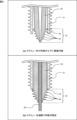
- FIG. 1 is an explanatory diagram that shows a schematic cross-sectional structure to illustrate a configuration example of a treatment device according to a first embodiment of the present invention.
- FIG. 2 is an explanatory diagram showing an example of the configuration of the tip end of the inner cylinder from a bird's-eye view.
- FIG. 3 is an explanatory diagram showing a schematic cross-sectional structure to show an example of the configuration of the tip portion of the inner cylinder.
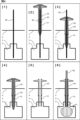
- FIG. 4 is an explanatory diagram that shows a schematic diagram of a treatment procedure (first half) using the treatment device of the present invention.
- FIG. 5 is an explanatory diagram that shows a schematic diagram of a treatment procedure (latter half) using the treatment device of the present invention.
- FIG. 1 is an explanatory diagram that shows a schematic cross-sectional structure to illustrate a configuration example of a treatment device according to a first embodiment of the present invention.
- FIG. 2 is an explanatory diagram showing an example of the configuration of the tip end of the inner cylinder
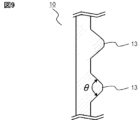
- FIG. 6 is an explanatory diagram that shows a schematic cross-sectional structure to illustrate an example of the configuration of a screw according to a second embodiment of the present invention.
- FIG. 7 is an explanatory diagram that shows a schematic cross-sectional structure to illustrate an example of the configuration of a screw according to a third embodiment of the present invention.
- FIG. 8 is an explanatory diagram showing a cross section of an example of a thread of a screw of the present invention.
- FIG. 9 is an explanatory diagram showing a cross section of another example of the thread of the screw of the present invention.
- a treatment device that integrates a cylindrical driver and an inner cylinder by inserting a guide pin ( Figure 1)
- a representative embodiment disclosed in the present application is a treatment instrument (100) including a cylindrical driver (20) capable of screwing a screw (10) into bone, an inner tube (30) that can be inserted into the driver, and a guide pin (60) that can be inserted into the inner tube, and is configured as follows:
- the screw has a thread (13) that can be tapped into the outer wall, and a through hole that allows the inner tube to pass from the head (11) to the tip along the central axis.
- a thread that can be tapped refers to a thread that can be cut around the periphery in conjunction with the action of screwing the screw to form a thread groove that meshes with the thread.
- the driver is configured so that it can be fitted into the head of the screw and connected to the screw by moving it along the central axis, and can transmit a rotational force around the central axis to the screw.
- the inner cylinder is inserted from the distal end of the driver through the through holes of the driver and the screw when the screw and the driver are connected, and has a tip portion (32) that protrudes proximally beyond the tip of the screw.
- the inner tube is inserted from the distal end of the driver when the driver is connected to the screw, and can be connected to the driver at the distal end (35, 36, 25, 26), and when connected to the driver, the tip protrudes proximally beyond the tip of the screw.
- the inner tube is connected to the screw by inserting the guide pin with the tip protruding proximally beyond the tip of the screw.
- the tongues bend toward the central axis and can move in the central axis direction within the through holes of the driver and screw (upper part of Figure 3).
- the guide pin is inserted into the inner tube, restricting the tongues from bending in the central axis direction, and the protrusions come into contact with the tip of the screw, restricting the inner tube from moving back along the central axis toward the through hole of the screw (lower part of Figure 3).
- the protrusions protrude outward (away from the central axis) beyond the inner wall of the through hole of the screw, restricting the screw from slipping out of the inner tube.
- the inner tube has a thread (34) that can be tapped on the outer circumferential surface of the tip.
- Screw threads The number of threads decreases from distal to proximal ( Figure 7) In the treatment device (100) of [1] to [3], the number of threads of the screw is greater on the distal side and smaller on the proximal side.
- thread refers to the thread, and the number of threads is a number that indicates the number of threads of the same screw groove.
- the outer diameter of the screw threads is smaller toward the proximal end, and the number of threads decreases toward the proximal end ( Figure 7).
- the outer diameter of the screw thread is larger on the distal side and smaller on the proximal side, and the number of threads is greater on the distal side and less on the proximal side.
- This invention can also be considered an invention of the screw alone.
- Screw Smaller diameter threads on the proximal side ( Figure 6)
- An exemplary embodiment disclosed herein is a screw (10) with threads that can tap bone into an outer wall when screwed, the outer diameter of the threads being larger distally and smaller proximally.
- Screw The number of threads decreases from distal to proximal ( Figure 7)
- An exemplary embodiment disclosed herein is a screw (10) with threads that can tap bone into the outer wall when screwed, the threads having more distal and less proximal threads.
- Screw The outer diameter of the thread is smaller toward the proximal end, and the number of threads decreases toward the proximal end ( Figure 7).
- An exemplary embodiment disclosed herein is a screw (10) having threads that can tap bone into an outer wall when screwed, the outer diameter of the threads being larger distally and smaller proximally, and the number of threads being more distally and less proximally.
- FIG. 1 is an explanatory diagram showing a schematic cross-sectional structure to show a configuration example of a treatment device 100 according to a first embodiment of the present invention.
- Fig. 1 is drawn with the scale of the central axis direction (vertical direction on the page) compressed and with emphasis on the direction along the patient's body surface (horizontal direction on the page). The same is true for the other drawings.
- the treatment instrument 100 of the present invention includes a cylindrical driver 20 capable of screwing a screw 10 into a bone, an inner tube 30 inserted into the driver 20, and a guide pin 60 inserted into the inner tube 30, and is configured as follows.
- the tip of the screw 10 is blunt so that a soft vertebral excavation device such as a balloon can be inserted and removed, and has a thread 13 that can tap bone or cement on the outer wall, and a through hole that can pass the inner tube 30 from the head 11 to the tip along the central axis.
- the driver 20 is configured to fit into the head 11 of the screw 10 by moving along the central axis and connect to the screw 10, and to transmit a rotational force around the central axis to the screw 10.
- the tip of the driver 20 may be formed in the shape of a hexagonal wrench (hexagonal column), and the head 11 of the screw 10 may be formed with a hexagonal groove (recess).
- the shape of the driver tip and the shape of the screw head may be other than hexagonal, such as a star shape, as long as they are engaged simply by inserting them. If the driver 20 is slid into the head of the screw 10 along the central axis, the tip of the driver 20 fits into the head 11 of the screw 10, making it possible to screw the screw with the driver 10, and the driver 10 can be easily removed by pulling out the driver 10.
- the head structure of the screw may further include a structure (not shown) with a U-shaped passageway to allow a spinal fixation rod to be secured, if necessary.
- the inner tube 30 is inserted from the distal end of the driver 20 through the through holes of the driver 20 and the screw 10 when the screw 10 and the driver 20 are connected, and has a tip portion 32 that protrudes proximally beyond the tip of the screw 10.
- the inner tube 30 is connected to the screw 10 by inserting a guide pin 60 with the tip portion 32 protruding proximally beyond the tip of the screw 10.
- the driver 20 and the inner tube 30 are configured so that they can be connected at their distal ends.
- the distal end of the driver 20 is provided with a cylindrical connection part 25 having a male screw 26 thread on the outer circumferential surface
- the distal end of the inner tube 30 is provided with a groove-shaped connection part 35 that can accommodate the cylinder, and a female screw 36 that engages with the male screw 26 is formed.
- the relationship of the convex and concave parts and the relationship of the male screw and the female screw may be reversed, or other connection mechanisms may be used. Also, as exemplified in FIG.
- the driver 20 is provided with a handle 27 and the inner tube 30 is provided with a handle 37, and it is preferable that they are integrated so that they are easy to grip when connected. Even if the connection is made with a screw as in this example, a latch mechanism (not shown) may be further provided to prevent the connection from coming loose.
- the tip (proximal end) of the inner tube 30 is divided into multiple tongues 31 in the direction along the central axis, and each of the multiple tongues 31 has a protrusion 33 in the direction away from the central axis.
- the protrusions 33 function as notches that prevent the screw 10 from slipping out of the inner tube 30, as described below, so the symbol 33 is referred to as a notch.
- the tongues 31 are formed, for example, by dividing the cylindrical inner tube 30 with slits from the tip side.
- the number of divisions can be any number, such as 4, 6, 2, or 3.
- some processing for example, heat treatment, processing to reduce thickness, processing to bond highly elastic metal
- the elasticity of the tongues 31 is designed to have an appropriate degree of bending.
- the notch 33 is pressed against the inner wall of the through hole, bending in the direction of the central axis to allow the inner tube 30 to pass, and when the notch 33 comes out proximal to the tip of the screw 10, the bending returns to its original state and the notch 33 catches on the tip of the screw 10. If the notch 33 has a smooth shape, even after the notch 33 emerges from the tip of the screw 10, the force used to pull out the inner tube 30 can be used to pull the notch 33 into the through hole of the screw 10, and the tongue 31 can be bent again in the direction of the central axis, allowing the inner tube 30 to be pulled out.
- the tip of the screw 10 is smoothly chamfered.
- a sixth step ([6]) in which a balloon 81 is introduced into the vertebral body 3 through the through hole of the screw 10, inflated, and then removed. At this time, the risk of the balloon 81 touching the tip of the screw 10 and damaging it can be reduced.
- FIG. 3 is an explanatory diagram showing a schematic cross-sectional structure to show an example of the configuration of the tip 32 of the inner tube 30.
- the above-mentioned tongue 31 bends toward the central axis, and can move in the central axis direction within the through hole.
- the tip 32 protrudes proximally beyond the tip of the screw 10, and the tongue 31 returns to its original bending state, so that the notch 33 comes into contact with the tip of the screw 10.
- the tip 32 of the inner cylinder 30 is provided with a thread 34 that can be tapped onto the outer circumferential surface.
- the thread 34 should be formed in a position that smoothly connects with the thread 13 of the screw 10 when the screw 10, driver 20, and inner cylinder 30 are integrated as described above. "Smoothly connected" means that the thread groove formed when the thread 34 of the inner cylinder 30 is screwed in is passed by the thread 13 of the screw 10 when the screw is screwed in further.
- This section describes treatment methods for spinal diseases using the treatment device 100 of the present invention, including artificial disc replacement, spinal fixation, vertebroplasty, and pedicle plasty.
- Fig. 4 and Fig. 5 are explanatory diagrams that show a typical procedure for treatment using the treatment device 100 of the present embodiment 1, with Fig. 4 showing the first half of the procedure and Fig. 5 showing the second half.
- Figs. 4 and 5 show vertebroplasty, but the method of inserting into the vertebral body is the same as in spinal fixation and vertebral body reinforcement surgery in artificial disc replacement (not shown).
- Figs. 4 and 5 show a typical cross section of the affected area of a patient, from the outside of the skin 4 through the pedicle 2 to the vertebral body 3, with the upper side of the page being the distal side and the lower side being the proximal side.
- Fig. 4 and Fig. 5 show a typical cross section of the affected area of a patient, from the outside of the skin 4 through the pedicle 2 to the vertebral body 3, with the upper side of the page being the distal side and the lower side being the proximal side.
- the scale of the central axis direction (vertical direction on the page) is compressed, and the direction along the patient's body surface (horizontal direction on the page) is emphasized.
- the pedicle 2 is located on both the left and right sides of the vertebral body 3, so the same treatment is performed on one vertebral body 3 from both the left and right, but Figs. 4 and 5 show only one of them.
- the cannula 80 is introduced into the vertebral body 3 through the through-holes of the driver 20 and the screw 10, and the balloon 81 is inflated inside the vertebral body 3.
- the balloon 81 is inflated by injecting a contrast agent through the cannula 80 and applying pressure.
- the purpose is to return the vertebral body 3 to its original size when the vertebral body 3 has a compression fracture due to osteoporosis or the like.
- the volume of cement that can be filled at one time using the cement filling tube 70 is approximately 1.5 ml. Therefore, for example, in the case of vertebroplasty for a fracture, the cement is repeatedly pumped out about three times from each side, a total of six to seven times, to fill about 10 ml of cement 1 into the vertebral body 3.
- the amount of cement filled is adjusted according to the condition of the bone.
- the treatment device 100 of the present invention allows the screw 10 to be screwed into the filled cement 1 immediately after the cement 1 is filled, making it suitable for procedures such as spinal fixation surgery, vertebral reinforcement surgery in artificial disc replacement surgery, vertebroplasty, and pedicle formation.
- the filled cement 1 is soft enough that the screw 10 can be screwed in without tapping using the threads 34 on the tip 32 of the inner tube 30. Similarly, the screw 10 can be screwed into the pedicle 2 without tapping using the tip 32 of the inner tube 30.
- the treatment instrument 100 of the present invention is also suitable for removing the screw 10. After incising the affected area and drilling a hole up to the head of the screw, the guide pin 60 is inserted into the screw 10, and the driver 20 is introduced along it up to the screw 10, and the driver 20 can be connected simply by pushing in the tip. The screw 10 can then be pulled out by rotating the driver 20.
- the screw 10 may adopt a configuration of this embodiment 2 or the following embodiment 3, or a combination of both.
- FIG. 6 is an explanatory diagram showing a cross-sectional structure of a screw 10 according to a second embodiment of the present invention.
- the outer diameter of the thread 13 of the screw 10 according to the second embodiment is inclined so that it is larger on the distal side ( dd ) and smaller on the proximal side ( dp ).
- the shaft diameter ( ds ) is 5.0 mm
- the outer diameter dd on the distal side is 6.5 mm
- the outer diameter dp on the proximal side is 5.2 mm.
- Figures 8 and 9 are explanatory diagrams showing schematic cross-sections of examples of the threads 13 of the screw of the present invention.
- FIG. 7 is an explanatory diagram showing a cross-sectional structure in order to show an example of the configuration of the screw 10 according to the third embodiment of the present invention.
- the number of threads of the thread 13 of the screw 10 according to the third embodiment is configured to be greater on the distal side and less on the proximal side.
- the thread refers to a thread
- the number of threads is a numerical value representing the number of threads of the same screw groove as one.
- the distal region T3 is triple threaded
- the intermediate region T2 is double threaded
- the proximal region T1 is single threaded.
- the thread (thread) 13-1 in the region T1 is tapped to form a thread groove, and the same thread (thread) 13-1 in the regions T2 and T3 is threaded along the thread groove.
- the second thread (thread) 13-2 is not in the region T1, so the thread (thread) 13-2 in the region T2 is tapped to form a thread groove, and the thread (thread) 13-2 in the region T3 is threaded along the thread groove.
- the third thread (thread) 13-3 does not exist in the regions T1 and T2, so the thread (thread) 13-3 in the region T3 is tapped to form a screw groove and is screwed in.
- a single thread is also formed in the tip portion 32 of the inner cylinder 20, which is an extension of the single thread in the region T1.
- the distal region T3 may have six threads
- the intermediate region T2 may have four threads
- the proximal region T1 may have a single thread.
- a tapered structure may also be adopted in which the outer diameter of the thread 13 of the screw 10 is larger on the distal side (d d ) and smaller on the proximal side (d p ).
- the thread angle ⁇ may be blunted to approximately 90° or more, and the edges may be smoothly chamfered.
- the present invention relates to a medical device, and can be particularly well suited for use in surgery in which cement is first filled inside the affected bone, and then a screw is screwed into the cement from the outside of the bone.
Abstract
A therapeutic instrument suitable for a procedure combining vertebroplasty and pedicle formation technique includes a screw (10), a cylindrical driver (20) capable of screwing the screw into bone, an inner cylinder (30) that can be inserted into the driver, and a guide pin (60) that can be inserted into the inner cylinder, wherein the screw has a thread (13) that can tap bone or cement into an outer wall (outer periphery) and a through hole (12) through which the inner cylinder can pass from the head to the tip of the screw, by moving the driver along the central axis, the driver fits into the head of the screw and connects with the screw, allowing the driver to transmit force in the rotational direction to the screw, and the inner cylinder has a notch such that where the inner cylinder is inserted from the distal end of the driver in a state in which the screw and the driver are connected to each other, a tip portion (32) of the inner cylinder protrudes from the tip of the screw, and where the guide pin is inserted, the inner cylinder protrudes to the outside and the screw does not come out.
Description
本発明は、治療器具およびスクリューに関し、特に、患部である骨の内側に予めセメントを充填しそのセメントに骨の外側からスクリュー(ねじ)を捩じ込む手術に好適に利用できるものである。
The present invention relates to a treatment instrument and screw, and is particularly suitable for use in surgery in which cement is first filled inside the affected bone and then a screw is screwed into the cement from the outside of the bone.
脊椎変性疾患の治療法として脊椎固定術や人工椎間板置換術が知られている。また脊椎の圧迫骨折の治療法として、椎体形成術や脊椎固定術が知られている。脊椎は、積み重なった椎体とそれを支えて上下方向に繋ぐ椎弓、椎弓根、上下の関節突起等からなる。椎体は、髄核とそれを囲む線維輪を上下に挟む円筒状の骨で、椎弓から延びる左右2個の椎弓根によって支えられている。椎弓は、上下の関節突起によって上下につながって椎弓根を介して椎体を支え、脊椎を形成している。圧迫骨折は、上下方向の圧迫によって椎体が押しつぶされて損傷する疾患である。椎体形成術は、押しつぶされた椎体を再建する手術であり、例えば医療用セメントを椎体内に充填する術式が採用される。脊椎固定術は、脊椎変性疾患に対して罹患した椎間を固定する術式であり、圧迫骨折に対してはその上下の健康な椎体を器具で固定する術式である。人工椎間板置換術は罹患した椎間に人工の椎間板を挿入する術式である。脊椎固定術では、複数の椎体にそれぞれ椎弓根からスクリューをねじ込み、スクリューの頭部を互いに上下方向に渡されたロッドに繋いで罹患椎間または骨折した椎体を固定する。罹患した椎体の状況により各疾患に対して、脊椎固定術、人工椎間板置換術、または椎体形成術が適宜選択されてまたは組み合わせて採用される。
Spinal fusion and artificial disc replacement are known as treatments for degenerative spinal diseases. Vertebroplasty and spinal fusion are known as treatments for compression fractures of the spine. The spine consists of stacked vertebral bodies, the vertebral arch that supports and connects them vertically, the pedicle, the upper and lower articular processes, etc. The vertebral body is a cylindrical bone that sandwiches the nucleus pulposus and the annulus fibrosus that surrounds it from above and below, and is supported by two pedicles extending from the vertebral arch. The vertebral arch is connected from above to below by the upper and lower articular processes, supports the vertebral body via the pedicle, and forms the spine. Compression fracture is a disease in which the vertebral body is crushed and damaged by vertical compression. Vertebroplasty is a surgery to reconstruct the crushed vertebral body, and for example, a surgical procedure is used to fill the vertebral body with medical cement. Spinal fusion is a surgical procedure to fix the affected intervertebral space for degenerative spinal diseases, and a surgical procedure to fix the healthy vertebral bodies above and below with instruments for compression fractures. Artificial disc replacement is a surgical procedure in which an artificial disc is inserted between affected vertebrae. In spinal fusion, screws are screwed into the pedicles of multiple vertebrae, and the heads of the screws are connected to rods that run vertically between each other to fix the affected vertebrae or fractured vertebrae. Depending on the condition of the affected vertebrae, spinal fusion, artificial disc replacement, or vertebroplasty are appropriately selected or combined for each disease.
これらの治療に使われる医療器具およびスクリューが、種々提案されている。
Various medical instruments and screws have been proposed for use in these treatments.
特許文献1には、椎弓根から椎体に向かってスクリューをねじ込むためのスクリュードライバが開示されている。スクリュードライバは、椎弓根スクリューを回転させるためのシャンクと、その周囲でシャンクが回転できるように支えるクランプ用スリーブと、そのクランプ用スリーブに取り付けてハンドルからの回転を伝達するアダプタスリーブによって構成されている。アダプタスリーブは着脱可能とされ、取り外すと椎弓根スクリューと接続されたシャンク及びクランプ用スリーブが残り、その結果手術医の処置地点の視野が改善されるとされる(第0014段落~第0015段落)。
Patent document 1 discloses a screwdriver for driving a screw from the pedicle to the vertebral body. The screwdriver is composed of a shank for rotating the pedicle screw, a clamping sleeve that supports the shank so that it can rotate around it, and an adapter sleeve that is attached to the clamping sleeve and transmits rotation from the handle. The adapter sleeve is removable, and when removed, the shank and clamping sleeve connected to the pedicle screw remain, which is said to improve the surgeon's view of the treatment site (paragraphs 0014 to 0015).
特許文献2には、脊椎ロッドを患者の椎骨に相互結合する脊椎固定のための医療器具が開示されている。椎骨に移植された骨アンカー(骨ねじ)が、種々の部品を使って、脊椎に沿って延びるロッドと接続される。
Patent document 2 discloses a medical device for spinal fixation that interconnects spinal rods with the patient's vertebrae. Bone anchors (bone screws) implanted in the vertebrae are connected to rods that run along the spine using various components.
特許文献3には、ねじ込んだ骨折部位から容易に抜去できるとされる医療用スクリューが開示されている。この医療用スクリューは、頭部から中心軸に沿って中空になっており、外側にはねじ部が設けられ、さらに内側の中空の先端近くには、ねじ部とは逆方向の逆内ねじ部が設けられている。この医療用スクリューをねじ込むときには、頭部に設けられた六角溝と噛み合う六角レンチ(図3)が用いられ、抜去するときには、先端に逆内ねじと噛み合う逆外ねじ部が設けられた抜去操作治具(図7)が用いられる。
Patent Document 3 discloses a medical screw that can be easily removed from the fracture site once it has been screwed in. This medical screw is hollow along the central axis from the head, has a threaded portion on the outside, and further inside, near the hollow tip, has a reverse internal thread that runs in the opposite direction to the threaded portion. When screwing in this medical screw, a hex wrench (Figure 3) that engages with the hexagonal groove on the head is used, and when removing it, a removal tool (Figure 7) is used, which has a reverse external thread at the tip that engages with the reverse internal thread.
一方、新しい術式も提案されている。
Meanwhile, new surgical techniques have also been proposed.
椎体形成術は、経皮的に施術されて侵襲が抑えられ、患者の負担を軽くすることができ、その結果、入院期間の短縮、ひいては医療費、介護費の削減にも寄与する。経皮的椎体形成術は、このように多くの症例で良好な成績を上げる一方、充填したセメントが脱転する合併症が報告されている。このような合併症を防ぐために、セメントを充填した後硬化する前に椎弓根からスクリューをセメント塊に挿入し、骨折した椎体を内固定(再建)する方法(椎体形成術と椎弓根形成術を併用する術式)が提案され(米澤嘉朗他,「骨粗鬆症性椎体偽関節に対する経皮的椎体形成術: PMMAと椎体内スクリューの併用」,骨折研究会論文,2006年,第28巻,pp.444-448,日本骨折治療学会)、多くの患者に適用されて好成績を収めている。この技術は圧迫骨折に対する椎体形成術のみだけではなく、骨粗鬆症を有する脊椎変性疾患に対する脊椎固定術さらには腰椎人工椎間板置換術における脊椎補強技術として有効である。
Vertebroplasty is performed percutaneously, which reduces invasiveness and reduces the burden on patients, thereby contributing to shortening hospital stays and reducing medical and nursing care costs. While percutaneous vertebroplasty has shown good results in many cases, complications such as dislodging of the filled cement have been reported. To prevent such complications, a method has been proposed in which a screw is inserted into the cement mass from the pedicle after filling and before it hardens, and the fractured vertebrae are internally fixed (reconstructed) (a procedure that combines vertebroplasty and pedicle plasty) (Yonezawa Yoshiro et al., "Percutaneous vertebroplasty for osteoporotic vertebral pseudarthrosis: combined use of PMMA and intravertebral screws," Fracture Research Society Paper, 2006, Vol. 28, pp. 444-448, Japanese Society of Fracture Treatment), which has been applied to many patients and has shown good results. This technique is effective not only for vertebroplasty for compression fractures, but also as a spinal reinforcement technique in spinal fixation for degenerative spinal diseases including osteoporosis and lumbar artificial disc replacement.
本発明者は、上述のような骨粗鬆症を有する脊椎疾患に対する人工椎間板置換術、脊椎固定術、椎体形成術、椎弓根形成術を併用する術式に適する医療器具およびスクリューの開発が十分ではないという課題を見出した。
The inventors have discovered a problem in that there has been insufficient development of medical instruments and screws suitable for combined surgical procedures involving artificial disc replacement, spinal fixation, vertebroplasty, and pedicle plasty for spinal diseases associated with osteoporosis as described above.
現在、骨粗鬆症を有する脊椎変性疾患に対する腰椎脊椎固定術や人工椎間板置換術では、土台となる脊椎骨の脆弱性により、ケージと呼ばれる椎間板置換材料や人工椎間板が椎体壁(終板)を穿破して沈降化したり、スクリューがゆるむなどの合併症が広く問題となっている 。これらの術式において脊椎補強技術は十分ではなく、また、これらの術式の中でセメントで椎体を補強する方法があるが、以下に挙げる理由により実用的ではない。体外(背中)から椎弓根を通して椎体に至る貫通孔を穿孔し、体外からその貫通孔を通してバルーンなどの機器で椎体掘削を行ったあとに、セメントを注入し、その後、セメント塊にスクリューをねじ込むこととなる。セメントを注入した後スクリューをねじ込むまでに時間がかかってしまうと、セメント塊の硬化が進みすぎてスクリューのねじ込みが困難になる。
Currently, in lumbar spinal fixation and artificial disc replacement for osteoporotic spinal degenerative diseases, complications such as the penetration of the vertebral wall (end plate) by the disc replacement material called a cage or the artificial disc, and the loosening of the screw, are widely problematic due to the fragility of the underlying vertebral bone.
The spinal reinforcement technology is insufficient in these surgical procedures, and although there is a method of reinforcing the vertebral body with cement, it is not practical for the following reasons. A through hole is drilled from outside the body (back) through the pedicle to the vertebral body, and the vertebral body is excavated from outside the body through the through hole with a balloon or other device, and then the cement is injected and the screw is screwed into the cement mass. If it takes too long to screw in the screw after injecting the cement, the cement mass hardens too much, making it difficult to screw in the screw.
特許文献1に示されるスクリュードライバは、同時にセメント注入カニューレの機能を有しており、器具を交換することなくシャンクを介してセメントを椎弓根スクリューに注入することができるとされている(第0058段落~第0068段落)。ただし、「椎弓根スクリューをねじ込んだ直後に、器具を交換することなく、シャンク2を介してセメントをカニューレが挿入されている椎弓根スクリュー30の中に注入でき」(第0068段落)とされるとおり、セメントを注入した後にセメント塊にスクリューをねじ込むことは想定されていない。
The screwdriver shown in Patent Document 1 also functions as a cement injection cannula, and is said to be able to inject cement into the pedicle screw via the shank without changing the instrument (paragraphs 0058 to 0068). However, as it is said that "immediately after the pedicle screw is screwed in, cement can be injected into the pedicle screw 30 into which the cannula is inserted via the shank 2 without changing the instrument" (paragraph 0068), it is not envisaged that the screw will be screwed into the cement mass after the cement has been injected.
特許文献2に示される医療器具においては、図9Aに示される注入組立体を使って骨セメントが、カニューレが挿入された骨アンカーの中に注入される。注入組立体のカニューレは、骨アンカーの頭部に図9Bに示される構造によってしっかりとシールされることによって、骨セメントが連結部分に漏れるのが防止されている(第0054段落)。ただしこの文献においても、「骨ねじ22は、さらにカニューレ挿入され窓を設けられ(図示せず)、カニューレ挿入されたねじにおける中央の中空通路から外側に開口部が延在し、挿入中にねじの外へ流体を押し出し、又はねじに隣接した材料の抜き取り中にねじの側部から中央の中空の通路へ流体を引き込む」(第0017段落)とされているように、セメントを注入した後にセメント塊にスクリューをねじ込むことは想定されていない。
In the medical device shown in Patent Document 2, bone cement is injected into a cannulated bone anchor using an injection assembly shown in FIG. 9A. The cannula of the injection assembly is tightly sealed to the head of the bone anchor by the structure shown in FIG. 9B, thereby preventing the bone cement from leaking into the connection portion (paragraph 0054). However, this document also does not anticipate screwing the screw into the cement mass after injecting the cement, as it states that "the bone screw 22 is further cannulated and fenestrated (not shown) with openings extending outward from a central hollow passage in the cannulated screw to push fluid out of the screw during insertion or to draw fluid from the side of the screw into the central hollow passage during extraction of material adjacent to the screw" (paragraph 0017).
これらの医療機器ではセメント注入後にセメント塊にスクリューをねじ込むことは想定されていないとは言っても、そのような使い方が不可能なわけではない。しかしながら、セメントを注入するために器具交換する手間(時間)を省くため、スクリューをねじ込むドライバーなどの器具がセメントを通すカニューレの機能を兼ねているので、使用後にセメントを洗い流す負担が重い。多くの場合、セメントを通す器具は再使用が禁じられ、使い捨て(ディスポーザル)とされている。
Although these medical devices are not designed to screw into the cement mass after the cement has been injected, such use is not impossible. However, to save the effort (time) of changing instruments to inject cement, instruments such as drivers used to screw in the screws also function as cannulas to pass the cement through, which means that it is a heavy burden to wash off the cement after use. In many cases, the instruments used to pass the cement are prohibited from being reused and are considered disposable.
また多くの場合、セメントが注入されるスクリューには側面にセメントが吐出する開口部が設けられている(上で引用した特許文献2の第0017段落を参照)。これは、セメント注入後にセメント塊にスクリューをねじ込む代わりに、スクリューの周囲にセメントを充填するための別の手段であり、特許文献2の他にも多くの医療器具がこの方法を前提として構成されている。しかし、上記横穴(セメントが吐出する側面の開口部)を有するスクリューでセメント充填を行う治療では、合併症を引き起こす危険性が指摘されている。スクリューの横穴からセメントを注入する際、横穴が小さいこと、高圧で充填する必要があること、セメント充填スペースを確保せずに充填すること等が重なることにより、セメントが椎体の外に血流に乗って流れ、肺塞栓症を起こすことがあり、重篤な合併症として報告されている。このように、治療機器として十分に適切な性能を備えているとは言えない。
In many cases, the screw into which the cement is injected has an opening on the side through which the cement is discharged (see paragraph 0017 of Patent Document 2 cited above). This is another means of filling the area around the screw with cement, instead of screwing the screw into the cement mass after the cement is injected, and many medical devices other than those in Patent Document 2 are designed based on this method. However, it has been pointed out that there is a risk of complications occurring in treatments in which cement is filled using a screw with the above-mentioned side hole (a side opening through which the cement is discharged). When cement is injected through the side hole of the screw, the side hole is small, it needs to be filled at high pressure, and the cement is filled without securing a space for filling it. This combination of factors can cause the cement to flow out of the vertebral body in the bloodstream, causing pulmonary embolism, which has been reported as a serious complication. As such, it cannot be said that the device has sufficient performance to be suitable as a treatment device.
整形外科医である本発明者は、さらに別の課題も見出した。セメント注入後にセメント塊にスクリューをねじ込む場合も、スクリューをねじ込んだ後に側面の吐出口からセメントを吐出させてスクリューと周囲の骨の結合を補強する場合も、将来スクリューを抜去する必要が生じる可能性について十分に考慮されていないという課題である。事実、椎体形成術と椎弓根形成術を併用する術式においてスクリューの抜去が必要とされるような症状に至った例はないものの、一般論としては、スクリューを挿入した椎骨に細菌感染症を生じてしまった場合、挿入したスクリューが誤って神経を刺激してしまう症状が後日に判明した場合など、スクリューの抜去が必要となる可能性が考えられる。また、後日症状が悪化して多椎間の脊椎固定術を行う必要が生じた場合等に、脊椎固定用にロッドとの接続が可能なスクリューに交換する必要があるため、スクリューの抜去まで考慮しておくことが求められる。
The present inventor, who is an orthopedic surgeon, has also found another problem. Whether the screw is screwed into the cement mass after cement injection or the cement is discharged from the side outlet after the screw is screwed in to reinforce the connection between the screw and the surrounding bone, the possibility of the need to remove the screw in the future is not fully considered. In fact, there have been no cases of symptoms requiring screw removal in a procedure that combines vertebroplasty and pedicle plasty. However, in general, it is possible that the screw may need to be removed if a bacterial infection occurs in the vertebra into which the screw was inserted, or if symptoms of the inserted screw accidentally irritating a nerve are discovered at a later date. In addition, if symptoms worsen at a later date and it becomes necessary to perform multi-level spinal fixation surgery, it is necessary to replace the screw with one that can be connected to a rod for spinal fixation, so it is necessary to consider even the removal of the screw.
一方、セメント注入後にセメント塊にスクリューをねじ込む場合も、スクリューをねじ込んだ後に側面の吐出口からセメントを吐出させてスクリューと周囲の骨の結合を補強する場合も、セメントで補強されたときにはスクリューは抜けにくくなる。十分に硬化する前のセメント塊にスクリューをねじ込むと、硬化後には非常に抜けにくくなる。またスクリュー側壁の吐出口からセメントを充填した場合は、スクリューの内腔に残ったセメントと外側のセメントが吐出口で繋がれたまま硬化するので、スクリューの回転が阻害されることとなる。抜去には吐出口のセメントをスクリューの回転によって破壊する必要があるからである。
On the other hand, whether the screw is screwed into the cement block after cement is injected, or the screw is screwed in and then cement is ejected from the side outlet to reinforce the bond between the screw and the surrounding bone, the screw will be difficult to remove if it is reinforced with cement. If the screw is screwed into a cement block before it has fully hardened, it will be very difficult to remove after it has hardened. Also, if cement is injected through the outlet on the side wall of the screw, the cement remaining in the screw cavity and the cement on the outside will harden while still connected by the outlet, preventing the screw from rotating. This is because to remove the screw, the cement at the outlet must be destroyed by rotating the screw.
骨にねじ込まれたスクリューの抜去には、例えば、特許文献3に記載されるようなスクリューが提案されているが、抜去するためには抜去操作治具(同文献の図7)をスクリューに装着する必要がある。そのためスクリューの内腔は空洞である必要があり、内腔を通してセメントを注入することはできない。内腔を通してセメントを注入したとしても内腔内にセメントが残してはならない。
For example, a screw as described in Patent Document 3 has been proposed for removing a screw that has been screwed into bone, but in order to remove the screw, an extraction tool (Figure 7 in the same document) must be attached to the screw. For this reason, the inner cavity of the screw must be hollow, and cement cannot be injected through the inner cavity. Even if cement is injected through the inner cavity, no cement must remain in the inner cavity.
以上のように、現行の医療機器はいずれも、上述のような椎体形成術と椎弓根形成術を併用する術式をはじめとして、骨粗鬆症を有する脊椎変性疾患・骨折に対する脊椎固定術、人工椎間板置換術の際の椎体補強手術、椎体形成術、椎弓根形成術を行う術式に十分に適するとは言えない。
As described above, none of the current medical devices are fully suitable for the above-mentioned procedures that combine vertebroplasty and pedicle plasty, as well as spinal fixation for degenerative spinal disease and fractures due to osteoporosis, vertebral reinforcement surgery during artificial disc replacement, vertebroplasty, and pedicle plasty.
本発明の目的は、骨粗鬆症を有する脊椎変性疾患・骨折に対する脊椎固定術、人工椎間板置換術の際の椎体補強手術、椎体形成術、椎弓根形成術を行う術式に適する治療器具およびスクリューを提供することである。本発明のさらなる目的は、セメントの充填に使う器具を最小限に抑え、洗浄の負担または洗浄を避けるための使い捨てを減らすことであり、さらなる別の目的は、スクリューの抜去を容易とすることである。
The object of the present invention is to provide a treatment instrument and screw suitable for spinal fixation surgery for osteoporotic spinal degenerative disease and fractures, vertebral reinforcement surgery during artificial disc replacement surgery, vertebroplasty, and pedicle plasty. A further object of the present invention is to minimize the number of instruments used for cement filling and to reduce the burden of cleaning or disposable items to avoid cleaning, and a further object is to facilitate removal of the screw.
このような課題を解決するための手段を以下に説明するが、その他の課題と新規な特徴は、本明細書の記述及び添付図面から明らかになるであろう。
Means for solving these problems are described below, but other problems and novel features will become apparent from the description of this specification and the accompanying drawings.
本発明の一実施の形態によれば、下記の通りである。
According to one embodiment of the present invention, it is as follows.
即ち、スクリューを骨にねじ込むことができる筒状のドライバーと、前記ドライバーに挿入されることができる内筒と、前記内筒に挿入されることができるガイドピンとを含む治療器具であって、以下のように構成される。
That is, it is a treatment instrument that includes a cylindrical driver that can screw a screw into bone, an inner tube that can be inserted into the driver, and a guide pin that can be inserted into the inner tube, and is configured as follows.
スクリューは、外壁(外周)に骨をタッピングすることができるねじ山と、中心軸に沿って頭部から先端まで内筒を通すことができる貫通孔とを有する。
The screw has threads on its outer wall (periphery) that can tap into bone, and a through hole that allows the inner tube to pass from the head to the tip along the central axis.
ドライバーは、中心軸に沿って移動させることによってスクリューの頭部に嵌まり、嵌まることによってスクリューと連結することができ、中心軸の周りを回る回転方向の力をスクリューに伝達することができるように構成される。
The driver is configured so that it can be fitted into the head of the screw by moving it along the central axis, and when fitted, it can connect with the screw, and can transmit a rotational force around the central axis to the screw.
内筒は、スクリューとドライバーが連結された状態で、ドライバーとスクリューの貫通孔を貫通してドライバーの遠位端から挿入されて、スクリューの先端よりも近位側に突出する先端部を有する。内筒はこの先端部がスクリューの先端よりも近位側に突出した状態で、ガイドピンが挿入されることにより、スクリューと接続される
ここで、近位(proximal)とは患者の体の中心線に近い側であり、遠位(distal)とは遠い側を指す医学用語である。セメントとは医療用の骨セメントであり、例えば、リン酸カルシウム、ポリメタクリル酸メチル(polymethylmethacrylate)を主成分とし、経時的に硬化する。 The inner cylinder has a tip end that is inserted from the distal end of the driver through the through hole of the driver and the screw when the screw and the driver are connected, and protrudes proximally from the tip of the screw. The inner cylinder is connected to the screw by inserting a guide pin with the tip end protruding proximally from the tip of the screw. Here, proximal is a medical term that refers to the side closer to the center line of the patient's body, and distal is a medical term that refers to the far side. The cement is a medical bone cement, for example, mainly composed of calcium phosphate and polymethylmethacrylate, and hardens over time.
ここで、近位(proximal)とは患者の体の中心線に近い側であり、遠位(distal)とは遠い側を指す医学用語である。セメントとは医療用の骨セメントであり、例えば、リン酸カルシウム、ポリメタクリル酸メチル(polymethylmethacrylate)を主成分とし、経時的に硬化する。 The inner cylinder has a tip end that is inserted from the distal end of the driver through the through hole of the driver and the screw when the screw and the driver are connected, and protrudes proximally from the tip of the screw. The inner cylinder is connected to the screw by inserting a guide pin with the tip end protruding proximally from the tip of the screw. Here, proximal is a medical term that refers to the side closer to the center line of the patient's body, and distal is a medical term that refers to the far side. The cement is a medical bone cement, for example, mainly composed of calcium phosphate and polymethylmethacrylate, and hardens over time.
前記一実施の形態によって得られる効果を簡単に説明すれば下記のとおりである。
The advantages achieved by the above embodiment can be briefly explained as follows:
すなわち、脊椎疾患に対する人工椎間板置換術、脊椎固定術、椎体形成術、椎弓根形成術を行う術式に適する治療器具を提供することができる。
In other words, it is possible to provide a treatment device suitable for the procedures of artificial disc replacement, spinal fixation, vertebroplasty, and pedicle plasty for spinal diseases.
1.実施の形態の概要
先ず、本願において開示される代表的な実施の形態について概要を説明する。代表的な実施の形態についての概要説明で括弧を付して参照する図面中の参照符号はそれが付された構成要素の概念に含まれるものを例示するに過ぎない。 1. Overview of the embodiment First, an overview of the representative embodiment disclosed in the present application will be described. In the overview of the representative embodiment, reference numerals in parentheses in the drawings refer only to components included in the concept of the components to which the reference numerals are attached.
先ず、本願において開示される代表的な実施の形態について概要を説明する。代表的な実施の形態についての概要説明で括弧を付して参照する図面中の参照符号はそれが付された構成要素の概念に含まれるものを例示するに過ぎない。 1. Overview of the embodiment First, an overview of the representative embodiment disclosed in the present application will be described. In the overview of the representative embodiment, reference numerals in parentheses in the drawings refer only to components included in the concept of the components to which the reference numerals are attached.
〔1〕筒状ドライバーと内筒をガイドピンの挿入で一体化する治療器具(図1)
本願において開示される代表的な実施の形態は、スクリュー(10)を骨にねじ込むことができる筒状のドライバー(20)と、前記ドライバーに挿入されることができる内筒(30)と、前記内筒に挿入されることができるガイドピン(60)とを含む治療器具(100)であって、以下のように構成される。 [1] A treatment device that integrates a cylindrical driver and an inner cylinder by inserting a guide pin (Figure 1)
A representative embodiment disclosed in the present application is a treatment instrument (100) including a cylindrical driver (20) capable of screwing a screw (10) into bone, an inner tube (30) that can be inserted into the driver, and a guide pin (60) that can be inserted into the inner tube, and is configured as follows:
前記スクリューは、外壁にタッピングすることができるねじ山(13)と、中心軸に沿って頭部(11)から先端まで前記内筒を通すことができる貫通孔とを有する。ここで、タッピングすることができるねじ山とは、スクリューをねじ込む動作に併せて周囲を削って、当該ねじ山と噛み合うねじ溝を形成することができるねじ山を指す。
The screw has a thread (13) that can be tapped into the outer wall, and a through hole that allows the inner tube to pass from the head (11) to the tip along the central axis. Here, a thread that can be tapped refers to a thread that can be cut around the periphery in conjunction with the action of screwing the screw to form a thread groove that meshes with the thread.
前記ドライバーは、前記中心軸に沿って移動させることによって前記スクリューの頭部に嵌まって前記スクリューと連結することができ、前記中心軸の周りを回る回転方向の力を前記スクリューに伝達することができるように構成されている。
The driver is configured so that it can be fitted into the head of the screw and connected to the screw by moving it along the central axis, and can transmit a rotational force around the central axis to the screw.
前記内筒は、前記スクリューと前記ドライバーが連結された状態で、前記ドライバーの遠位端から前記ドライバーと前記スクリューの貫通孔を貫通して挿入されて、前記スクリューの先端よりも近位側に突出する先端部(32)を有する。
The inner cylinder is inserted from the distal end of the driver through the through holes of the driver and the screw when the screw and the driver are connected, and has a tip portion (32) that protrudes proximally beyond the tip of the screw.
前記内筒は、前記ドライバーが前記スクリューと連結された状態で、前記ドライバーの遠位端から挿入され当該遠位端で前記ドライバーと接続可能(35,36,25,26)であり、前記ドライバーと接続された状態で前記先端部がスクリューの先端よりも近位側に突出する。
The inner tube is inserted from the distal end of the driver when the driver is connected to the screw, and can be connected to the driver at the distal end (35, 36, 25, 26), and when connected to the driver, the tip protrudes proximally beyond the tip of the screw.
前記内筒は、前記先端部が前記スクリューの先端よりも近位側に突出した状態で、前記ガイドピンが挿入されることにより、前記スクリューと接続される。
The inner tube is connected to the screw by inserting the guide pin with the tip protruding proximally beyond the tip of the screw.
これにより、脊椎疾患に対する人工椎間板置換術、脊椎固定術、椎体形成術、椎弓根形成術を併用する術式に適する治療器具を提供することができる。
This makes it possible to provide a treatment device suitable for combined surgical procedures for spinal diseases that include artificial disc replacement, spinal fixation, vertebroplasty, and pedicle plasty.
〔2〕スクリューとドライバーと内筒の連結手段(図1~図3)
〔1〕の治療器具(100)において、前記内筒の近位端は、前記中心軸に沿った方向に複数の舌片(31)に分割され、前記複数の舌片のそれぞれは、前記中心軸から離れる方向に凸部(33)を有する。 [2] Means for connecting the screw, driver, and inner cylinder (Figs. 1 to 3)
In the treatment instrument (100) of [1], the proximal end of the inner tube is divided into a plurality of tongues (31) in a direction along the central axis, and each of the plurality of tongues has a convex portion (33) in a direction away from the central axis.
前記内筒は、連結されたドライバーとスクリューに挿入されるときに、前記舌片が前記中心軸側に撓んで、当該ドライバーと当該スクリューの貫通孔内を前記中心軸方向に移動することができる(図3上側)。前記内筒が、連結されたドライバーとスクリューに挿入され、当該ドライバーと遠位端で接続されたときには、前記ガイドピンが当該内筒に挿入されることにより、前記複数の舌片が前記中心軸方向に撓まないように規制され、前記凸部を前記スクリューの先端に接触させて、前記内筒が前記中心軸に沿って前記スクリューの貫通孔方向に戻る動きが規制される(図3下側)。換言すると、前記凸部はスクリューの貫通孔の内壁よりも外側(前記中心軸から離れる方向)に突出して、前記スクリューが前記内筒から抜けないように規制する。
When the inner tube is inserted into the connected driver and screw, the tongues bend toward the central axis and can move in the central axis direction within the through holes of the driver and screw (upper part of Figure 3). When the inner tube is inserted into the connected driver and screw and connected to the driver at its distal end, the guide pin is inserted into the inner tube, restricting the tongues from bending in the central axis direction, and the protrusions come into contact with the tip of the screw, restricting the inner tube from moving back along the central axis toward the through hole of the screw (lower part of Figure 3). In other words, the protrusions protrude outward (away from the central axis) beyond the inner wall of the through hole of the screw, restricting the screw from slipping out of the inner tube.
これにより、スクリューとドライバーと内筒を一体化する操作を単純化することができる。即ち、ガイドピンを挿入することによって一体化し、抜去することによってそれぞれを分離することができる。
This simplifies the process of integrating the screw, driver, and inner cylinder. That is, they can be integrated by inserting the guide pin, and separated by removing it.
〔3〕内筒の先端部にもタッピングねじ山
〔1〕または〔2〕の治療器具(100)において、前記内筒は、前記先端部の外周面にタッピングすることができるねじ山(34)を備える。 [3] Tapping thread also on the tip of the inner tube In the treatment instrument (100) of [1] or [2], the inner tube has a thread (34) that can be tapped on the outer circumferential surface of the tip.
〔1〕または〔2〕の治療器具(100)において、前記内筒は、前記先端部の外周面にタッピングすることができるねじ山(34)を備える。 [3] Tapping thread also on the tip of the inner tube In the treatment instrument (100) of [1] or [2], the inner tube has a thread (34) that can be tapped on the outer circumferential surface of the tip.
これにより、脊椎骨にスクリューをねじ込むときの抵抗を小さくすることができる。
This reduces resistance when screwing into the vertebrae.
〔4〕スクリューのねじ山の外径:近位側ほど小径(図6)
〔1〕~〔3〕の治療器具(100)において、前記スクリューのねじ山の外径は、遠位側(dd)ほど大きく、近位側(dp)ほど小さい。 [4] Outer diameter of screw thread: Smaller diameter on the proximal side (Figure 6)
In the treatment instrument (100) of [1] to [3], the outer diameter of the thread of the screw is larger on the distal side (d d ) and smaller on the proximal side (d p ).
これにより、スクリューの抜去を容易にすることができる。
This makes it easier to remove the screw.
〔5〕スクリューのねじ山:遠位から近位に向かってねじ山の条数が減少(図7)
〔1〕~〔3〕の治療器具(100)において、前記スクリューのねじ山の条数は、遠位側ほど多く、近位側ほど少ない。ここで条とはねじ山を指し、条数は同じねじ溝をねじ山を1つとしてその数を表す数値である。 [5] Screw threads: The number of threads decreases from distal to proximal (Figure 7)
In the treatment device (100) of [1] to [3], the number of threads of the screw is greater on the distal side and smaller on the proximal side. Here, the term "thread" refers to the thread, and the number of threads is a number that indicates the number of threads of the same screw groove.
これにより、スクリューの抜去を容易にすることができる。
This makes it easier to remove the screw.
〔6〕スクリューのねじ山の外径は近位側ほど小径で、近位に向かってねじ山の条数が減少(図7)
〔1〕~〔3〕の治療器具(100)において、前記スクリューのねじ山の外径は、遠位側ほど大きく、近位側ほど小さく、かつ、ねじ山の条数は、遠位側ほど多く、近位側ほど少ない。 [6] The outer diameter of the screw threads is smaller toward the proximal end, and the number of threads decreases toward the proximal end (Figure 7).
In the treatment instrument (100) of [1] to [3], the outer diameter of the screw thread is larger on the distal side and smaller on the proximal side, and the number of threads is greater on the distal side and less on the proximal side.
上述の〔4」と〔5〕の特徴を併せ持たせることにより、スクリューの抜去をさらに容易にすることができる。
By combining the features of [4] and [5] above, screw removal can be made even easier.
本発明は、スクリュー単体の発明としても位置づけられる。
This invention can also be considered an invention of the screw alone.
〔7〕スクリュー:近位側ほど小径のねじ山(図6)
本願において開示される代表的な実施の形態は、ねじ込まれるときに外壁に骨をタッピングすることができるねじ山を備えるスクリュー(10)であって、前記ねじ山の外径は、遠位側ほど大きく、近位側ほど小さい。 [7] Screw: Smaller diameter threads on the proximal side (Figure 6)
An exemplary embodiment disclosed herein is a screw (10) with threads that can tap bone into an outer wall when screwed, the outer diameter of the threads being larger distally and smaller proximally.
これにより、抜去の容易なスクリューを提供することができる。
This allows for the provision of screws that are easy to remove.
〔8〕スクリュー:遠位から近位に向かってねじ山の条数が減少(図7)
本願において開示される代表的な実施の形態は、ねじ込まれるときに外壁に骨をタッピングすることができるねじ山を備えるスクリュー(10)であって、前記ねじ山の条数は、遠位側ほど多く、近位側ほど少ない。 [8] Screw: The number of threads decreases from distal to proximal (Figure 7)
An exemplary embodiment disclosed herein is a screw (10) with threads that can tap bone into the outer wall when screwed, the threads having more distal and less proximal threads.
これにより、抜去の容易なスクリューを提供することができる。
This allows for the provision of screws that are easy to remove.
〔9〕スクリュー:ねじ山の外径は近位側ほど小径で、近位に向かってねじ山の条数が減少(図7)
本願において開示される代表的な実施の形態は、ねじ込まれるときに外壁に骨をタッピングすることができるねじ山を備えるスクリュー(10)であって、前記ねじ山の外径は、遠位側ほど大きく、近位側ほど小さく、且つ、前記ねじ山の条数は、遠位側ほど多く、近位側ほど少ない。 [9] Screw: The outer diameter of the thread is smaller toward the proximal end, and the number of threads decreases toward the proximal end (Figure 7).
An exemplary embodiment disclosed herein is a screw (10) having threads that can tap bone into an outer wall when screwed, the outer diameter of the threads being larger distally and smaller proximally, and the number of threads being more distally and less proximally.
上述の〔6」と〔7〕の特徴を併せ持たせることにより、抜去がさらに容易なスクリューを提供することができる。
By combining the features of [6] and [7] above, it is possible to provide a screw that is even easier to remove.
2.実施の形態の詳細
実施の形態について更に詳述する。 2. Details of the embodiment The embodiment will be described in further detail.
実施の形態について更に詳述する。 2. Details of the embodiment The embodiment will be described in further detail.
〔実施形態1〕
図1は、本発明の第1実施形態である治療器具100の構成例を示すために、断面構造を模式的に示す説明図である。発明の理解を助けるために、図1は、中心軸方向(紙面上下方向)の縮尺を圧縮し、患者の体表面に沿った方向(紙面左右方向)を強調して描画されている。他の図面についても同様である。 [Embodiment 1]
Fig. 1 is an explanatory diagram showing a schematic cross-sectional structure to show a configuration example of atreatment device 100 according to a first embodiment of the present invention. To facilitate understanding of the invention, Fig. 1 is drawn with the scale of the central axis direction (vertical direction on the page) compressed and with emphasis on the direction along the patient's body surface (horizontal direction on the page). The same is true for the other drawings.
図1は、本発明の第1実施形態である治療器具100の構成例を示すために、断面構造を模式的に示す説明図である。発明の理解を助けるために、図1は、中心軸方向(紙面上下方向)の縮尺を圧縮し、患者の体表面に沿った方向(紙面左右方向)を強調して描画されている。他の図面についても同様である。 [Embodiment 1]
Fig. 1 is an explanatory diagram showing a schematic cross-sectional structure to show a configuration example of a
本発明の治療器具100は、スクリュー10を骨にねじ込むことができる筒状のドライバー20と、ドライバー20に挿入される内筒30と、内筒30に挿入されるガイドピン60とを含み、以下のように構成される。
The treatment instrument 100 of the present invention includes a cylindrical driver 20 capable of screwing a screw 10 into a bone, an inner tube 30 inserted into the driver 20, and a guide pin 60 inserted into the inner tube 30, and is configured as follows.
スクリュー10は、先端はバルーンなどの柔らかい椎体掘削機器を出し入れすることが可能なように鈍となっており、外壁に骨やセメントをタッピングすることができるねじ山13と、中心軸に沿って頭部11から先端まで内筒30を通すことができる貫通孔とを有する。ドライバー20は、中心軸に沿って移動させることによってスクリュー10の頭部11に嵌まってスクリュー10と連結され、中心軸の周りを回る回転方向の力をスクリュー10に伝達することができるように構成されている。例えば、ドライバー20の先端には六角レンチの形状(6角柱)、スクリュー10の頭部11には6角形の溝(凹部)が、それぞれ形成されているとよい。ドライバー先端の形状とスクリュー頭部の形状は、挿入するだけで噛み合えばよく、6角形以外の形状、例えば星形などでもよい。中心軸に沿ってドライバー20をスクリュー10の頭部にスライドさせればドライバー20の先端がスクリュー10の頭部11に嵌まり込んで、ドライバー10によるスクリューのねじ込みが可能な状態になり、ドライバー10を引き抜けば簡単に外れる。スクリューの頭側の構造は、必要に応じて脊椎固定用ロッドを固定できるようなU字型の通路を有する構造(図示は省略)をさらに設けてもよい。
The tip of the screw 10 is blunt so that a soft vertebral excavation device such as a balloon can be inserted and removed, and has a thread 13 that can tap bone or cement on the outer wall, and a through hole that can pass the inner tube 30 from the head 11 to the tip along the central axis. The driver 20 is configured to fit into the head 11 of the screw 10 by moving along the central axis and connect to the screw 10, and to transmit a rotational force around the central axis to the screw 10. For example, the tip of the driver 20 may be formed in the shape of a hexagonal wrench (hexagonal column), and the head 11 of the screw 10 may be formed with a hexagonal groove (recess). The shape of the driver tip and the shape of the screw head may be other than hexagonal, such as a star shape, as long as they are engaged simply by inserting them. If the driver 20 is slid into the head of the screw 10 along the central axis, the tip of the driver 20 fits into the head 11 of the screw 10, making it possible to screw the screw with the driver 10, and the driver 10 can be easily removed by pulling out the driver 10. The head structure of the screw may further include a structure (not shown) with a U-shaped passageway to allow a spinal fixation rod to be secured, if necessary.
内筒30は、スクリュー10とドライバー20が連結された状態で、ドライバー20の遠位端から前記ドライバー20とスクリュー10の貫通孔を貫通して挿入されて、スクリュー10の先端よりも近位側に突出する先端部32を有する。内筒30は、先端部32がスクリュー10の先端よりも近位側に突出した状態で、ガイドピン60が挿入されることにより、スクリュー10と接続される。
The inner tube 30 is inserted from the distal end of the driver 20 through the through holes of the driver 20 and the screw 10 when the screw 10 and the driver 20 are connected, and has a tip portion 32 that protrudes proximally beyond the tip of the screw 10. The inner tube 30 is connected to the screw 10 by inserting a guide pin 60 with the tip portion 32 protruding proximally beyond the tip of the screw 10.
これにより、脊椎疾患に対する人工椎間板置換術、脊椎固定術、椎体形成術、椎弓根形成術を行う術式に適する治療器具を提供することができる。
This makes it possible to provide a treatment device suitable for procedures such as artificial disc replacement, spinal fixation, vertebroplasty, and pedicle plasty for spinal diseases.
スクリュー10とドライバー20と内筒30とを一体化するための構造の一例について説明する。
An example of a structure for integrating the screw 10, driver 20, and inner cylinder 30 is described below.
図1に示すように、ドライバー20と内筒30とは、遠位端で接続することできるように構成されている。ドライバー20の遠位端には、外周面に雄ネジ26のネジ山を持つ円筒状の接続部25が設けられており、内筒30の遠位端には、その円筒を収納できる溝状の接続部35が設けられ、上記雄ネジ26と噛み合う雌ネジ36が形成されている。凹凸の関係、雄ネジと雌ネジの関係は逆でもよいし、他の接続機構であってもよい。また、図1に例示されるように、ドライバー20にはハンドル27が、内筒30にはハンドル37が設けられ、接続されたときに握りやすいように一体化する構成が好ましい。この例のようにねじで接続するであっても、接続が外れないようにするラッチ機構(図示は省略)をさらに設けてもよい。
As shown in FIG. 1, the driver 20 and the inner tube 30 are configured so that they can be connected at their distal ends. The distal end of the driver 20 is provided with a cylindrical connection part 25 having a male screw 26 thread on the outer circumferential surface, and the distal end of the inner tube 30 is provided with a groove-shaped connection part 35 that can accommodate the cylinder, and a female screw 36 that engages with the male screw 26 is formed. The relationship of the convex and concave parts and the relationship of the male screw and the female screw may be reversed, or other connection mechanisms may be used. Also, as exemplified in FIG. 1, the driver 20 is provided with a handle 27 and the inner tube 30 is provided with a handle 37, and it is preferable that they are integrated so that they are easy to grip when connected. Even if the connection is made with a screw as in this example, a latch mechanism (not shown) may be further provided to prevent the connection from coming loose.
図2に示すように、内筒30の先端(近位端)は、中心軸に沿った方向に複数の舌片31に分割され、複数の舌片31のそれぞれは、中心軸から離れる方向に凸部33を備える。凸部33は後述のようにスクリュー10が内筒30から抜けないように規制するノッチの機能を有するので、符号33はノッチとして参照される。
As shown in FIG. 2, the tip (proximal end) of the inner tube 30 is divided into multiple tongues 31 in the direction along the central axis, and each of the multiple tongues 31 has a protrusion 33 in the direction away from the central axis. The protrusions 33 function as notches that prevent the screw 10 from slipping out of the inner tube 30, as described below, so the symbol 33 is referred to as a notch.
複数の舌片31は、例えば、円筒状の内筒30を先端側からスリットで分割することによって形成される。分割数は例えば、4分割、6分割、2分割、3分割など任意である。また適度な弾性を持たせるために、何らかの加工(例えば、熱処理、厚みを薄くする加工、弾性の強い金属を貼り合わせる加工)を施してもよい。舌片31の弾性は適度な撓みを持つように設計される。たとえば、内筒30がドライバー20の貫通孔を通過するときには、貫通孔の内壁にノッチ33が押し付けられることによって中心軸方向に撓んで内筒30の通過を可能とし、ノッチ33がスクリュー10の先端よりも近位側に出ると、撓みが元に戻ってノッチ33がスクリュー10の先端に引っかかるように設計される。ノッチ33を滑らかな形状とすれば、スクリュー10の先端からノッチ33が出た後も、内筒30を引き抜く力でノッチ33をスクリュー10の貫通孔内に引き込み、舌片31を中心軸方向に再び撓ませることによって、内筒30を引き抜くことができるように構成することができる。
The tongues 31 are formed, for example, by dividing the cylindrical inner tube 30 with slits from the tip side. The number of divisions can be any number, such as 4, 6, 2, or 3. In addition, in order to provide appropriate elasticity, some processing (for example, heat treatment, processing to reduce thickness, processing to bond highly elastic metal) may be performed. The elasticity of the tongues 31 is designed to have an appropriate degree of bending. For example, when the inner tube 30 passes through the through hole of the driver 20, the notch 33 is pressed against the inner wall of the through hole, bending in the direction of the central axis to allow the inner tube 30 to pass, and when the notch 33 comes out proximal to the tip of the screw 10, the bending returns to its original state and the notch 33 catches on the tip of the screw 10. If the notch 33 has a smooth shape, even after the notch 33 emerges from the tip of the screw 10, the force used to pull out the inner tube 30 can be used to pull the notch 33 into the through hole of the screw 10, and the tongue 31 can be bent again in the direction of the central axis, allowing the inner tube 30 to be pulled out.
スクリュー10の先端は、なめらかに面取りされているとより好適である。図4と図5を引用して後述する椎体形成術と椎弓根形成術を併用する骨の治療方法において、スクリュー10の貫通孔を通してバルーン81を椎体3に導入して膨らませた後に取り出す第6ステップ([6])があるが、このときにバルーン81がスクリュー10の先端に触れて損傷する危険を下げることができる。
It is more preferable that the tip of the screw 10 is smoothly chamfered. In the bone treatment method using vertebroplasty and pedicle plasty in combination, which will be described later with reference to Figures 4 and 5, there is a sixth step ([6]) in which a balloon 81 is introduced into the vertebral body 3 through the through hole of the screw 10, inflated, and then removed. At this time, the risk of the balloon 81 touching the tip of the screw 10 and damaging it can be reduced.
スクリュー10とドライバー20と内筒30とを一体化する機構の説明に戻る。
Let's return to the explanation of the mechanism that integrates the screw 10, driver 20, and inner cylinder 30.
図3は、内筒30の先端部32の構成例を示すために、断面構造を模式的に示す説明図である。上側の(a)に示すように、内筒30は、連結されたドライバー20とスクリュー10に挿入されるときに、上述の舌片31が中心軸側に撓んで、貫通孔内を中心軸方向に移動することができる。下側の(b)に示すように、内筒30が、連結されたドライバー20とスクリュー10に挿入され、上述したようにドライバー20と遠位端で接続されたときには、先端部32がスクリュー10の先端よりも近位側に突出し、舌片31の撓みが戻ってノッチ33がスクリュー10の先端に接触する状態となる。この状態で、ガイドピン60が内筒30に挿入されることにより、内筒30を引き抜こうとしても舌片31が中心軸方向に撓むことができなくなり、ノッチ33がスクリュー10の貫通孔の径よりも外側に突出し、内筒30が中心軸に沿って遠位方向、即ち、スクリュー10の貫通孔方向に戻る動きが規制される。簡単に言えば、スクリュー10が内筒30から抜けようとすると、スクリュー10の先端にノッチ33が接触して抜けないように規制される。
3 is an explanatory diagram showing a schematic cross-sectional structure to show an example of the configuration of the tip 32 of the inner tube 30. As shown in (a) on the upper side, when the inner tube 30 is inserted into the connected driver 20 and screw 10, the above-mentioned tongue 31 bends toward the central axis, and can move in the central axis direction within the through hole. As shown in (b) on the lower side, when the inner tube 30 is inserted into the connected driver 20 and screw 10 and is connected to the driver 20 at the distal end as described above, the tip 32 protrudes proximally beyond the tip of the screw 10, and the tongue 31 returns to its original bending state, so that the notch 33 comes into contact with the tip of the screw 10. In this state, when the guide pin 60 is inserted into the inner tube 30, the tongue 31 cannot bend in the central axis direction even if the inner tube 30 is pulled out, and the notch 33 protrudes outward beyond the diameter of the through hole of the screw 10, and the movement of the inner tube 30 in the distal direction along the central axis, i.e., returning toward the through hole of the screw 10, is restricted. Simply put, when the screw 10 tries to come out of the inner cylinder 30, the notch 33 comes into contact with the tip of the screw 10, preventing it from coming out.
これにより、スクリュー10とドライバー20と内筒30とを一体化する操作を単純化することができる。即ち、ガイドピン60を挿入することによって一体化し、抜去することによってそれぞれを分離することができる。
This simplifies the process of integrating the screw 10, driver 20, and inner cylinder 30. That is, they can be integrated by inserting the guide pin 60, and separated by removing it.
内筒30の先端部32には、外周面にタッピングすることができるねじ山34を備えるとより好適である。このねじ山34は、スクリュー10とドライバー20と内筒30が上述のように一体化されたときに、スクリュー10のねじ山13となめらかにつながるような位置に形成されるとよい。なめらかにつながるとは、内筒30のねじ山34がねじ込まれる時に形成したねじ溝を、さらに深くねじ込むときにスクリュー10のねじ山13が通過することをいう。
It is more preferable that the tip 32 of the inner cylinder 30 is provided with a thread 34 that can be tapped onto the outer circumferential surface. The thread 34 should be formed in a position that smoothly connects with the thread 13 of the screw 10 when the screw 10, driver 20, and inner cylinder 30 are integrated as described above. "Smoothly connected" means that the thread groove formed when the thread 34 of the inner cylinder 30 is screwed in is passed by the thread 13 of the screw 10 when the screw is screwed in further.
これにより、スクリュー10とドライバー20と内筒30を一体化して骨にねじ込むときの抵抗が抑えられ、施術者は大きな力をかけずにねじ込むことができる。
This reduces resistance when screwing the screw 10, driver 20, and inner cylinder 30 into the bone, allowing the practitioner to screw in the screw without exerting a large amount of force.
本発明の治療器具100を使った、脊椎疾患に対する人工椎間板置換術、脊椎固定術、椎体形成術、椎弓根形成術を行う治療方法について説明する。
This section describes treatment methods for spinal diseases using the treatment device 100 of the present invention, including artificial disc replacement, spinal fixation, vertebroplasty, and pedicle plasty.
図4と図5は、本実施形態1の治療器具100を使った治療の手順を、模式的に示す説明図であり、図4はその手順の前半を、図5は後半をそれぞれ示す。図4および5は椎体形成術を図示したものになるが、椎体に挿入する方法としては脊椎固定術、人工椎間板置換術における椎体補強手術も同様(図示は省略)である。図4と図5は、紙面上側を遠位、下側を近位とし、皮膚4の外側から椎弓根2を経て椎体3に至る、患者の患部断面を模式的に示したものである。中心軸方向(紙面上下方向)の縮尺を圧縮し、患者の体表面に沿った方向(紙面左右方向)を強調して描画されている点は、図1等と同様である。椎弓根2は椎体3の左右それぞれにあるので、1つの椎体3に対して左右から同様の施術が行われるが、図4と図5はその一方を示している。
Fig. 4 and Fig. 5 are explanatory diagrams that show a typical procedure for treatment using the treatment device 100 of the present embodiment 1, with Fig. 4 showing the first half of the procedure and Fig. 5 showing the second half. Figs. 4 and 5 show vertebroplasty, but the method of inserting into the vertebral body is the same as in spinal fixation and vertebral body reinforcement surgery in artificial disc replacement (not shown). Figs. 4 and 5 show a typical cross section of the affected area of a patient, from the outside of the skin 4 through the pedicle 2 to the vertebral body 3, with the upper side of the page being the distal side and the lower side being the proximal side. As with Fig. 1, etc., the scale of the central axis direction (vertical direction on the page) is compressed, and the direction along the patient's body surface (horizontal direction on the page) is emphasized. The pedicle 2 is located on both the left and right sides of the vertebral body 3, so the same treatment is performed on one vertebral body 3 from both the left and right, but Figs. 4 and 5 show only one of them.
第1ステップ([1]):患者の背中の体表面である皮膚4から、患部である椎体3に至る皮下組織を切開して穿孔し、ガイドピン60を、椎弓根2を通って椎体3まで導入する。
First step ([1]): The subcutaneous tissue from the skin 4, which is the surface of the patient's back, to the affected vertebral body 3 is incised and perforated, and a guide pin 60 is introduced through the pedicle 2 to the vertebral body 3.
第2ステップ([2]):スクリュー10とドライバー20を連結し、その内側の貫通孔に内筒30を挿入してスクリュー10の先端から先端部が突き出させた状態に組み合わせ、内筒30をガイドピン60に被せるようにして、ガイドピン60に沿って患者の体内に挿入する。
Second step ([2]): The screw 10 and driver 20 are connected, and the inner tube 30 is inserted into the through hole on the inside of the screw 10 so that the tip of the screw 10 protrudes from the tip of the screw 10. The inner tube 30 is then placed over the guide pin 60, and inserted into the patient's body along the guide pin 60.
第3ステップ([3]):スクリュー10とドライバー20と内筒30が連結された状態で、ガイドピン60に沿って近位方向にさらに押しこみ、内筒30とスクリュー10の先端を椎弓根2にねじ込む。
Third step ([3]): With the screw 10, driver 20, and inner tube 30 connected, push them further in the proximal direction along the guide pin 60, and screw the inner tube 30 and the tip of the screw 10 into the pedicle 2.
第4ステップ([4]):スクリュー10の先端が椎体3の入り口付近に達するまでねじ込んだ後、ガイドピン60を抜去する。このとき、内筒30のノッチ33は、スクリュー10の先端に接して内筒30が自然に抜けない程度に抑止しているが、ガイドピン60が引き抜かれたことによって、内筒30を引き抜く力によって舌片31が簡単に中心軸方向に撓んで内筒30を引き抜くことができる状態になっている。
Fourth step ([4]): After the tip of the screw 10 has been screwed in until it reaches the entrance of the vertebral body 3, the guide pin 60 is removed. At this time, the notch 33 of the inner tube 30 is in contact with the tip of the screw 10, preventing the inner tube 30 from being pulled out naturally. However, by removing the guide pin 60, the tongue 31 is easily bent in the direction of the central axis by the force of pulling out the inner tube 30, allowing the inner tube 30 to be pulled out.
第5ステップ([5]):内筒30を抜去する。このとき、このとき、ドライバー20はスクリュー10の頭部11に単に差し込まれた状態にあるので、抜けないように押さえておく。特に図示していないが、このステップでは必要に応じて、ドライバー20とスクリュー10の貫通孔を通して補強のためのセメント充填を行うために椎体掘削機器を導入して椎体3内を掘削してもよい。
Fifth step ([5]): Remove the inner cylinder 30. At this time, the driver 20 is simply inserted into the head 11 of the screw 10, so it is held down so that it does not come out. Although not shown in the figure, in this step, if necessary, a vertebral body excavation device may be introduced through the through-hole of the driver 20 and the screw 10 to excavate the inside of the vertebral body 3 in order to fill the vertebral body with cement for reinforcement.
第6ステップ([6]):ドライバー20とスクリュー10の貫通孔を通しカニューレ80を椎体3内に導入し、椎体3内でバルーン81を膨らませる。例えば、バルーン81は、カニューレ80を通して造影剤を注入し、圧力をかけることによって膨らませる。骨粗鬆症などにより、椎体3が圧迫骨折している場合に、椎体3を元の大きさに戻す目的である。
Sixth step ([6]): The cannula 80 is introduced into the vertebral body 3 through the through-holes of the driver 20 and the screw 10, and the balloon 81 is inflated inside the vertebral body 3. For example, the balloon 81 is inflated by injecting a contrast agent through the cannula 80 and applying pressure. The purpose is to return the vertebral body 3 to its original size when the vertebral body 3 has a compression fracture due to osteoporosis or the like.
第7ステップ([7]):ドライバー20とスクリュー10の貫通孔からカニューレ80を引き抜き、代わりにセメント充填管70を挿入して、椎体3内にセメント1を注入する。セメント充填管70によって1回で充填することができるセメントの容量は約1.5mlであるので、例えば、骨折に対する椎体形成術の場合は、左右から約3回ずつ計6回~7回のセメントの送出を繰り返して、椎体3内に約10mlのセメント1を充填する。椎体形成術以外の、脊椎固定術、人工椎間板置換術における椎体補強手術に適用する場合には、骨の状態に応じてセメントの充填量を調整する。
Seventh step ([7]): The cannula 80 is removed from the through-holes of the driver 20 and screw 10, and instead the cement filling tube 70 is inserted to inject the cement 1 into the vertebral body 3. The volume of cement that can be filled at one time using the cement filling tube 70 is approximately 1.5 ml. Therefore, for example, in the case of vertebroplasty for a fracture, the cement is repeatedly pumped out about three times from each side, a total of six to seven times, to fill about 10 ml of cement 1 into the vertebral body 3. When applied to spinal fixation surgery and vertebral reinforcement surgery in artificial disc replacement surgery other than vertebroplasty, the amount of cement filled is adjusted according to the condition of the bone.
第8ステップ([8]):ドライバー20とスクリュー10の貫通孔からセメント充填管70を引き抜く。
Eighth step ([8]): Pull out the cement filling tube 70 from the through hole of the driver 20 and the screw 10.
第9ステップ([9]):ドライバー20を使ってスクリュー10を、充填したセメント1内にねじ込む。
Ninth step ([9]): Use the driver 20 to screw the screw 10 into the filled cement 1.
第10ステップ([10]):ドライバー20を引き抜き、切開した皮膚4を縫合して治療が完了する。
Tenth step ([10]): The driver 20 is removed, the incised skin 4 is sutured, and the treatment is completed.
以上のように、本発明の治療器具100によれば、セメント1を充填した後すぐに、スクリュー10を充填されたセメント1にねじ込むことができるので、脊椎固定術、人工椎間板置換術における椎体補強手術、椎体形成術、椎弓根形成術を行う術式に好適である。
As described above, the treatment device 100 of the present invention allows the screw 10 to be screwed into the filled cement 1 immediately after the cement 1 is filled, making it suitable for procedures such as spinal fixation surgery, vertebral reinforcement surgery in artificial disc replacement surgery, vertebroplasty, and pedicle formation.
充填されたセメント1は、内筒30の先端部32のねじ山34を使ってタッピングしなくても、スクリュー10をねじ込むことができるほど、十分に柔らかい。また、椎弓根2にも同様に、内筒30の先端部32によるタッピングなしでも、スクリュー10をねじ込むことができる。
The filled cement 1 is soft enough that the screw 10 can be screwed in without tapping using the threads 34 on the tip 32 of the inner tube 30. Similarly, the screw 10 can be screwed into the pedicle 2 without tapping using the tip 32 of the inner tube 30.
本発明の治療器具100は、スクリュー10の抜去にも適している。患部を切開し、スクリュー頭部まで穿孔した後、ガイドピン60をスクリュー10に差し込み、それに沿ってドライバー20をスクリュー10まで導入し、先端を押し込むだけで、ドライバー20を連結させることができる。その後、ドライバー20を回転させることによって、スクリュー10を引き抜くことができる。
The treatment instrument 100 of the present invention is also suitable for removing the screw 10. After incising the affected area and drilling a hole up to the head of the screw, the guide pin 60 is inserted into the screw 10, and the driver 20 is introduced along it up to the screw 10, and the driver 20 can be connected simply by pushing in the tip. The screw 10 can then be pulled out by rotating the driver 20.
〔実施形態2〕
本発明のスクリュー10は、抜去をさらに容易にするために、本実施形態2または次の実施形態3あるいはその両方を組み合わせた形態を採用することができる。 [Embodiment 2]
In order to make thescrew 10 of the present invention easier to remove, the screw 10 may adopt a configuration of this embodiment 2 or the following embodiment 3, or a combination of both.
本発明のスクリュー10は、抜去をさらに容易にするために、本実施形態2または次の実施形態3あるいはその両方を組み合わせた形態を採用することができる。 [Embodiment 2]
In order to make the
図6は、本発明の第2実施形態であるスクリュー10の構成例を示すために、断面構造を模式的に示す説明図である。第2実施形態のスクリュー10のねじ山13の外径は、遠位側(dd)ほど大きく、近位側(dp)ほど小さくなるように、傾斜をもたせる。例えば、シャフト径(ds)=5.0mmのとき、遠位側の外径dd=6.5mm、近位側の外径dp=5.2mmとする。
6 is an explanatory diagram showing a cross-sectional structure of a screw 10 according to a second embodiment of the present invention. The outer diameter of the thread 13 of the screw 10 according to the second embodiment is inclined so that it is larger on the distal side ( dd ) and smaller on the proximal side ( dp ). For example, when the shaft diameter ( ds ) is 5.0 mm, the outer diameter dd on the distal side is 6.5 mm and the outer diameter dp on the proximal side is 5.2 mm.
図8と図9は、本発明のスクリューのねじ山13の例を、断面で模式的に示す説明図である。上の例では、ねじ山の角度(thread angle)θ=60°としたが、図8に例示するように、θ=90°に拡大することもできる。またねじ山13の先端部は、図9に例示するように、なめらかに面取りの処理を施しておくことがより好適である。万一、ねじ山13が神経に触れたとしても、悪影響を抑えることができる。
Figures 8 and 9 are explanatory diagrams showing schematic cross-sections of examples of the threads 13 of the screw of the present invention. In the above example, the thread angle θ = 60°, but as shown in Figure 8, it can be expanded to θ = 90°. It is also preferable to smoothly chamfer the tip of the thread 13, as shown in Figure 9. Even if the thread 13 should come into contact with a nerve, adverse effects can be suppressed.
〔実施形態3〕
図7は、本発明の第3実施形態であるスクリュー10の構成例を示すために、断面構造を模式的に示す説明図である。第3実施形態のスクリュー10のねじ山13の条数は、遠位側ほど多く、近位側ほど少なくなるように構成されている。ここで条とはねじ山を指し、条数は同じねじ溝をねじ山を1つとしてその数を表す数値である。図7の例では、遠位側の領域T3ではトリプルスレッド、中間領域T2ではダブルスレッド、近位側の領域T1ではシングルスレッドである。スクリュー10をねじ込む動作を想定すると、領域T1のスレッド(ねじ山)13-1がタッピングして形成したねじ溝を、領域T2、T3の同じスレッド(ねじ山)13-1が辿ってねじ込まれる。2本目のスレッド(ねじ山)13-2は、領域T1にはないので、領域T2のスレッド(ねじ山)13-2がタッピングしてねじ溝を形成し、領域T3のスレッド(ねじ山)13-2がそのねじ溝に沿ってねじ込まれる。3本目のスレッド(ねじ山)13-3は、領域T1、T2にはないので、領域T3のスレッド(ねじ山)13-3がタッピングしてねじ溝を形成してねじ込まれる。なお、内筒20の先端部32にも領域T1のシングルスレッドが延長されたシングルスレッドが形成されている。 [Embodiment 3]
FIG. 7 is an explanatory diagram showing a cross-sectional structure in order to show an example of the configuration of thescrew 10 according to the third embodiment of the present invention. The number of threads of the thread 13 of the screw 10 according to the third embodiment is configured to be greater on the distal side and less on the proximal side. Here, the thread refers to a thread, and the number of threads is a numerical value representing the number of threads of the same screw groove as one. In the example of FIG. 7, the distal region T3 is triple threaded, the intermediate region T2 is double threaded, and the proximal region T1 is single threaded. Assuming the operation of screwing the screw 10, the thread (thread) 13-1 in the region T1 is tapped to form a thread groove, and the same thread (thread) 13-1 in the regions T2 and T3 is threaded along the thread groove. The second thread (thread) 13-2 is not in the region T1, so the thread (thread) 13-2 in the region T2 is tapped to form a thread groove, and the thread (thread) 13-2 in the region T3 is threaded along the thread groove. The third thread (thread) 13-3 does not exist in the regions T1 and T2, so the thread (thread) 13-3 in the region T3 is tapped to form a screw groove and is screwed in. A single thread is also formed in the tip portion 32 of the inner cylinder 20, which is an extension of the single thread in the region T1.
図7は、本発明の第3実施形態であるスクリュー10の構成例を示すために、断面構造を模式的に示す説明図である。第3実施形態のスクリュー10のねじ山13の条数は、遠位側ほど多く、近位側ほど少なくなるように構成されている。ここで条とはねじ山を指し、条数は同じねじ溝をねじ山を1つとしてその数を表す数値である。図7の例では、遠位側の領域T3ではトリプルスレッド、中間領域T2ではダブルスレッド、近位側の領域T1ではシングルスレッドである。スクリュー10をねじ込む動作を想定すると、領域T1のスレッド(ねじ山)13-1がタッピングして形成したねじ溝を、領域T2、T3の同じスレッド(ねじ山)13-1が辿ってねじ込まれる。2本目のスレッド(ねじ山)13-2は、領域T1にはないので、領域T2のスレッド(ねじ山)13-2がタッピングしてねじ溝を形成し、領域T3のスレッド(ねじ山)13-2がそのねじ溝に沿ってねじ込まれる。3本目のスレッド(ねじ山)13-3は、領域T1、T2にはないので、領域T3のスレッド(ねじ山)13-3がタッピングしてねじ溝を形成してねじ込まれる。なお、内筒20の先端部32にも領域T1のシングルスレッドが延長されたシングルスレッドが形成されている。 [Embodiment 3]
FIG. 7 is an explanatory diagram showing a cross-sectional structure in order to show an example of the configuration of the
領域の数、条の数については、適宜変更することができる。例えば、遠位側の領域T3では6スレッド、中間領域T2では4スレッド、近位側の領域T1ではシングルスレッドとしてもよい。
The number of regions and threads can be changed as appropriate. For example, the distal region T3 may have six threads, the intermediate region T2 may have four threads, and the proximal region T1 may have a single thread.
ねじ山の条数を遠位側から近位側に向かって徐々に少なくすることによって、抜去の容易なスクリュー10を提供することができる。
By gradually reducing the number of threads from the distal side to the proximal side, it is possible to provide a screw 10 that is easy to remove.
また、図7にも例示しているように、実施形態2と同様に、スクリュー10のねじ山13の外径は、遠位側(dd)ほど大きく、近位側(dp)ほど小さくなるように、傾斜をもたせる構造を併せて採用してもよい。
As shown in FIG. 7, similarly to the second embodiment, a tapered structure may also be adopted in which the outer diameter of the thread 13 of the screw 10 is larger on the distal side (d d ) and smaller on the proximal side (d p ).
本実施形態3においても、実施形態2で図8と図9を引用して説明したのと同様に、ねじ山の角度θを約90°かそれ以上に鈍らせ、また、なめらかに面取りの処理を施してもよい。
In this third embodiment, as in the second embodiment described with reference to Figures 8 and 9, the thread angle θ may be blunted to approximately 90° or more, and the edges may be smoothly chamfered.
以上本発明者によってなされた発明を実施形態に基づいて具体的に説明したが、本発明はそれに限定されるものではなく、その要旨を逸脱しない範囲において種々変更可能であることは言うまでもない。
The invention made by the inventor has been specifically described above based on an embodiment, but it goes without saying that the invention is not limited thereto and can be modified in various ways without departing from the gist of the invention.
本発明は、治療器具に関し、特に、患部である骨の内側に予めセメントを充填しそのセメントに骨の外側からスクリュー(ねじ)を捩じ込む手術に好適に利用することができる。
The present invention relates to a medical device, and can be particularly well suited for use in surgery in which cement is first filled inside the affected bone, and then a screw is screwed into the cement from the outside of the bone.
1 セメント
2 椎弓根
3 椎体
4 皮膚
8 椎体内の空洞
10 スクリュー
11 スクリューの頭部
12 スクリューの外壁
13 スクリューのねじ山
20 ドライバー
25 内筒との接続部
26 雄ネジ
27 ドライバーのハンドル
30 内筒
31 内筒の舌片
32 内筒の先端部
33 ノッチ
34 内筒先端部のねじ山
35 ドライバーとの接続部
36 雌ネジ
37 内筒のハンドル
60 ガイドピン
70 セメント充填管
80 カニューレ
81 バルーン
100 治療器具
REFERENCE SIGNSLIST 1 Cement 2 Pedicle 3 Vertebral body 4 Skin 8 Cavity in vertebral body 10 Screw 11 Head of screw 12 Outer wall of screw 13 Screw thread 20 Driver 25 Connection with inner tube 26 Male thread 27 Handle of driver 30 Inner tube 31 Tongue of inner tube 32 Tip of inner tube 33 Notch 34 Thread at tip of inner tube 35 Connection with driver 36 Female thread 37 Handle of inner tube 60 Guide pin 70 Cement filling tube 80 Cannula 81 Balloon 100 Treatment instrument
2 椎弓根
3 椎体
4 皮膚
8 椎体内の空洞
10 スクリュー
11 スクリューの頭部
12 スクリューの外壁
13 スクリューのねじ山
20 ドライバー
25 内筒との接続部
26 雄ネジ
27 ドライバーのハンドル
30 内筒
31 内筒の舌片
32 内筒の先端部
33 ノッチ
34 内筒先端部のねじ山
35 ドライバーとの接続部
36 雌ネジ
37 内筒のハンドル
60 ガイドピン
70 セメント充填管
80 カニューレ
81 バルーン
100 治療器具
REFERENCE SIGNS
Claims (9)
- スクリューを骨にねじ込むことができる筒状のドライバーと、前記ドライバーに挿入されることができる内筒と、前記内筒に挿入されることができるガイドピンとを含む治療器具であって、
前記スクリューは、外壁に骨をタッピングすることができるねじ山と、中心軸に沿って頭部から先端まで前記内筒を通すことができる貫通孔とを有し、
前記ドライバーは、前記中心軸に沿って移動させることによって前記スクリューの頭部に嵌まって前記スクリューと連結することができ、前記中心軸の周りを回る回転方向の力を前記スクリューに伝達することができるように構成され、
前記内筒は、前記ドライバーが前記スクリューと連結された状態で、前記ドライバーの遠位端から挿入され当該遠位端で前記ドライバーと接続可能であり、前記ドライバーと接続された状態で前記先端部がスクリューの先端よりも近位側に突出し、
前記内筒は、前記スクリューと前記ドライバーが連結された状態で、前記ドライバーの遠位端から前記ドライバーと前記スクリューの貫通孔を貫通して挿入されて、前記スクリューの先端よりも近位側に突出する先端部を有し、
前記内筒は、前記先端部が前記スクリューの先端よりも近位側に突出した状態で、前記ガイドピンが挿入されることにより、前記スクリューと接続される、
治療器具。 A medical instrument including a cylindrical driver capable of screwing a screw into a bone, an inner cylinder capable of being inserted into the driver, and a guide pin capable of being inserted into the inner cylinder,
The screw has a thread on an outer wall capable of tapping a bone, and a through hole through which the inner cylinder can pass from the head to the tip along a central axis,
The driver is configured to be able to fit into the head of the screw and connect with the screw by moving along the central axis, and to be able to transmit a rotational force around the central axis to the screw;
the inner cylinder is inserted from a distal end of the driver in a state where the driver is connected to the screw, and can be connected to the driver at the distal end, and when connected to the driver, the tip portion protrudes proximally beyond the tip of the screw;
the inner cylinder is inserted from the distal end of the driver through the through holes of the driver and the screw when the screw and the driver are coupled together, and has a tip portion that protrudes proximally beyond the tip of the screw;
The inner cylinder is connected to the screw by inserting the guide pin in a state in which the tip portion protrudes proximally beyond the tip of the screw.
Therapeutic equipment. - 請求項1において、
前記内筒の近位端は、前記中心軸に沿った方向に複数の舌片に分割され、前記複数の舌片のそれぞれは、前記中心軸から離れる方向に凸部を有し、
前記内筒は、連結されたドライバーとスクリューに挿入されるときに、前記舌片が前記中心軸側に撓んで、当該ドライバーと当該スクリューの貫通孔内を前記中心軸方向に移動することができ、
前記内筒が、連結されたドライバーとスクリューに挿入され、当該ドライバーと遠位端で接続されたときに、前記ガイドピンが当該内筒に挿入されることにより、前記複数の舌片が前記中心軸方向に撓まないように規制され、前記凸部を前記スクリューの先端部に接触させて、前記内筒が前記中心軸に沿って前記スクリューの貫通孔方向に戻る動きが規制される、
治療器具。 In claim 1,
The proximal end of the inner tube is divided into a plurality of tongues in a direction along the central axis, and each of the plurality of tongues has a protruding portion in a direction away from the central axis,
When the inner cylinder is inserted into the connected driver and screw, the tongue is bent toward the central axis and can move in the central axis direction within the through holes of the driver and the screw,
When the inner tube is inserted into the coupled driver and screw and connected to the driver at the distal end, the guide pin is inserted into the inner tube, thereby restricting the plurality of tongues from bending in the direction of the central axis, and bringing the protrusion into contact with the tip of the screw, restricting the movement of the inner tube back along the central axis toward the through hole of the screw.
Therapeutic equipment. - 請求項1または請求項2において、
前記内筒は、前記先端部の外周面にタッピングすることができるねじ山を備える、
治療器具。 In claim 1 or 2,
The inner cylinder has a thread that can be tapped on the outer peripheral surface of the tip portion.
Therapeutic equipment. - 請求項1において、
前記スクリューのねじ山の外径は、遠位側ほど大きく、近位側ほど小さい、
治療器具。 In claim 1,
The outer diameter of the screw thread is larger on the distal side and smaller on the proximal side.
Therapeutic equipment. - 請求項1において、
前記スクリューのねじ山の条数は、遠位側ほど多く、近位側ほど少ない、
治療器具。 In claim 1,
The number of threads of the screw is more on the distal side and less on the proximal side.
Therapeutic equipment. - 請求項1において、
前記スクリューのねじ山の外径は、遠位側ほど大きく、近位側ほど小さく、
前記スクリューのねじ山の条数は、遠位側ほど多く、近位側ほど少ない、
治療器具。 In claim 1,
The outer diameter of the thread of the screw is larger on the distal side and smaller on the proximal side,
The number of threads of the screw is more on the distal side and less on the proximal side.
Therapeutic equipment. - ねじ込まれるときに外壁に骨をタッピングすることができるねじ山を備えるスクリューであって、
前記ねじ山の外径は、遠位側ほど大きく、近位側ほど小さい、
スクリュー。 A screw having a thread capable of tapping bone into an outer wall when screwed in,
The outer diameter of the thread is larger on the distal side and smaller on the proximal side.
screw. - ねじ込まれるときに外壁に骨をタッピングすることができるねじ山を備えるスクリューであって、
前記ねじ山の条数は、遠位側ほど多く、近位側ほど少ない、
スクリュー。 A screw having a thread capable of tapping bone into an outer wall when screwed in,
The number of threads is greater on the distal side and less on the proximal side.
screw. - ねじ込まれるときに外壁に骨をタッピングすることができるねじ山を備えるスクリューであって、
前記ねじ山の外径は、遠位側ほど大きく、近位側ほど小さく、
前記ねじ山の条数は、遠位側ほど多く、近位側ほど少ない、
スクリュー。
A screw having a thread capable of tapping bone into an outer wall when screwed in,
The outer diameter of the thread is larger on the distal side and smaller on the proximal side,
The number of threads is greater on the distal side and less on the proximal side.
screw.
Priority Applications (3)
| Application Number | Priority Date | Filing Date | Title |
|---|---|---|---|
| JP2022574438A JP7300133B1 (en) | 2022-09-28 | 2022-09-28 | therapeutic instruments and screws |
| PCT/JP2022/036147 WO2024069795A1 (en) | 2022-09-28 | 2022-09-28 | Therapeutic instrument and screw |
| JP2023090298A JP7329895B1 (en) | 2022-09-28 | 2023-05-31 | therapeutic instruments and screws |
Applications Claiming Priority (1)
| Application Number | Priority Date | Filing Date | Title |
|---|---|---|---|
| PCT/JP2022/036147 WO2024069795A1 (en) | 2022-09-28 | 2022-09-28 | Therapeutic instrument and screw |
Publications (1)
| Publication Number | Publication Date |
|---|---|
| WO2024069795A1 true WO2024069795A1 (en) | 2024-04-04 |
Family
ID=86900566
Family Applications (1)
| Application Number | Title | Priority Date | Filing Date |
|---|---|---|---|
| PCT/JP2022/036147 WO2024069795A1 (en) | 2022-09-28 | 2022-09-28 | Therapeutic instrument and screw |
Country Status (2)
| Country | Link |
|---|---|
| JP (2) | JP7300133B1 (en) |
| WO (1) | WO2024069795A1 (en) |
Citations (4)
| Publication number | Priority date | Publication date | Assignee | Title |
|---|---|---|---|---|
| US20090187194A1 (en) * | 2008-01-17 | 2009-07-23 | Hamada James S | One step entry pedicular preparation device and disc access system |
| US20190053888A1 (en) * | 2014-03-03 | 2019-02-21 | Tenjin LLC | Implant placement systems and one-handed methods for tissue fixation using same |
| JP2019521790A (en) * | 2016-07-13 | 2019-08-08 | メドス・インターナショナル・エスエイアールエルMedos International SARL | Bone anchor assembly and associated instrument |
| JP2019136504A (en) * | 2018-02-09 | 2019-08-22 | ビーダーマン・テクノロジーズ・ゲゼルシャフト・ミット・ベシュレンクテル・ハフツング・ウント・コンパニー・コマンディートゲゼルシャフトBiedermann Technologies Gmbh & Co. Kg | System of bone anchor and elongate instrument |
Family Cites Families (1)
| Publication number | Priority date | Publication date | Assignee | Title |
|---|---|---|---|---|
| EP2398413B1 (en) | 2009-02-10 | 2014-05-21 | Synthes GmbH | Screw with variable diameter cannulation and driver |
-
2022
- 2022-09-28 JP JP2022574438A patent/JP7300133B1/en active Active
- 2022-09-28 WO PCT/JP2022/036147 patent/WO2024069795A1/en unknown
-
2023
- 2023-05-31 JP JP2023090298A patent/JP7329895B1/en active Active
Patent Citations (4)
| Publication number | Priority date | Publication date | Assignee | Title |
|---|---|---|---|---|
| US20090187194A1 (en) * | 2008-01-17 | 2009-07-23 | Hamada James S | One step entry pedicular preparation device and disc access system |
| US20190053888A1 (en) * | 2014-03-03 | 2019-02-21 | Tenjin LLC | Implant placement systems and one-handed methods for tissue fixation using same |
| JP2019521790A (en) * | 2016-07-13 | 2019-08-08 | メドス・インターナショナル・エスエイアールエルMedos International SARL | Bone anchor assembly and associated instrument |
| JP2019136504A (en) * | 2018-02-09 | 2019-08-22 | ビーダーマン・テクノロジーズ・ゲゼルシャフト・ミット・ベシュレンクテル・ハフツング・ウント・コンパニー・コマンディートゲゼルシャフトBiedermann Technologies Gmbh & Co. Kg | System of bone anchor and elongate instrument |
Also Published As
| Publication number | Publication date |
|---|---|
| JP7300133B1 (en) | 2023-06-29 |
| JP2024049314A (en) | 2024-04-09 |
| JP7329895B1 (en) | 2023-08-21 |
Similar Documents
| Publication | Publication Date | Title |
|---|---|---|
| AU2004292408B2 (en) | Fenestrated bone tap and method | |
| EP1257212B9 (en) | Apparatus for providing anterior trans-sacral access to spinal vertebrae | |
| AU2009239515B2 (en) | Posterior spinal fastener | |
| US7963967B1 (en) | Bone preparation tool | |
| US7641657B2 (en) | Method and apparatus for providing posterior or anterior trans-sacral access to spinal vertebrae | |
| US8157806B2 (en) | Apparatus and methods for vertebral augmentation | |
| US20030050644A1 (en) | Systems and methods for accessing and treating diseased or fractured bone employing a guide wire | |
| KR20120028873A (en) | Minimally invasive spine augmentation and stabilization system and method | |
| US20090264941A1 (en) | Guide sleeve for accessing a vertebral body and related methods of use | |
| KR200409151Y1 (en) | Thread pipe for operation vertebral boby | |
| US9597118B2 (en) | Bone anchor apparatus and method | |
| KR20080059219A (en) | Apparatus and methods for vertebral augmentation | |
| WO2024069795A1 (en) | Therapeutic instrument and screw | |
| KR200397033Y1 (en) | Surgical device for vertebral body | |
| KR200361374Y1 (en) | Surgical device for spiral vertebral column | |
| KR200404913Y1 (en) | Needle For Spine Surgery | |
| CN113768599A (en) | Bone cement intramedullary nail fixing system |