KR20080059219A - Apparatus and methods for vertebral augmentation - Google Patents
Apparatus and methods for vertebral augmentation Download PDFInfo
- Publication number
- KR20080059219A KR20080059219A KR1020087009124A KR20087009124A KR20080059219A KR 20080059219 A KR20080059219 A KR 20080059219A KR 1020087009124 A KR1020087009124 A KR 1020087009124A KR 20087009124 A KR20087009124 A KR 20087009124A KR 20080059219 A KR20080059219 A KR 20080059219A
- Authority
- KR
- South Korea
- Prior art keywords
- vertebral body
- cannula
- rod
- vertebral
- damaged
- Prior art date
Links
- 0 CC1(*)CCCC1 Chemical compound CC1(*)CCCC1 0.000 description 3
Images


Classifications
-
- A—HUMAN NECESSITIES
- A61—MEDICAL OR VETERINARY SCIENCE; HYGIENE
- A61B—DIAGNOSIS; SURGERY; IDENTIFICATION
- A61B17/00—Surgical instruments, devices or methods, e.g. tourniquets
- A61B17/56—Surgical instruments or methods for treatment of bones or joints; Devices specially adapted therefor
- A61B17/58—Surgical instruments or methods for treatment of bones or joints; Devices specially adapted therefor for osteosynthesis, e.g. bone plates, screws, setting implements or the like
- A61B17/88—Osteosynthesis instruments; Methods or means for implanting or extracting internal or external fixation devices
-
- A—HUMAN NECESSITIES
- A61—MEDICAL OR VETERINARY SCIENCE; HYGIENE
- A61B—DIAGNOSIS; SURGERY; IDENTIFICATION
- A61B17/00—Surgical instruments, devices or methods, e.g. tourniquets
- A61B17/56—Surgical instruments or methods for treatment of bones or joints; Devices specially adapted therefor
- A61B17/58—Surgical instruments or methods for treatment of bones or joints; Devices specially adapted therefor for osteosynthesis, e.g. bone plates, screws, setting implements or the like
- A61B17/68—Internal fixation devices, including fasteners and spinal fixators, even if a part thereof projects from the skin
- A61B17/70—Spinal positioners or stabilisers ; Bone stabilisers comprising fluid filler in an implant
- A61B17/7074—Tools specially adapted for spinal fixation operations other than for bone removal or filler handling
- A61B17/7076—Tools specially adapted for spinal fixation operations other than for bone removal or filler handling for driving, positioning or assembling spinal clamps or bone anchors specially adapted for spinal fixation
- A61B17/7077—Tools specially adapted for spinal fixation operations other than for bone removal or filler handling for driving, positioning or assembling spinal clamps or bone anchors specially adapted for spinal fixation for moving bone anchors attached to vertebrae, thereby displacing the vertebrae
-
- A—HUMAN NECESSITIES
- A61—MEDICAL OR VETERINARY SCIENCE; HYGIENE
- A61B—DIAGNOSIS; SURGERY; IDENTIFICATION
- A61B17/00—Surgical instruments, devices or methods, e.g. tourniquets
- A61B17/02—Surgical instruments, devices or methods, e.g. tourniquets for holding wounds open; Tractors
-
- A—HUMAN NECESSITIES
- A61—MEDICAL OR VETERINARY SCIENCE; HYGIENE
- A61B—DIAGNOSIS; SURGERY; IDENTIFICATION
- A61B17/00—Surgical instruments, devices or methods, e.g. tourniquets
- A61B17/02—Surgical instruments, devices or methods, e.g. tourniquets for holding wounds open; Tractors
- A61B17/025—Joint distractors
-
- A—HUMAN NECESSITIES
- A61—MEDICAL OR VETERINARY SCIENCE; HYGIENE
- A61B—DIAGNOSIS; SURGERY; IDENTIFICATION
- A61B17/00—Surgical instruments, devices or methods, e.g. tourniquets
- A61B17/56—Surgical instruments or methods for treatment of bones or joints; Devices specially adapted therefor
- A61B17/58—Surgical instruments or methods for treatment of bones or joints; Devices specially adapted therefor for osteosynthesis, e.g. bone plates, screws, setting implements or the like
- A61B17/68—Internal fixation devices, including fasteners and spinal fixators, even if a part thereof projects from the skin
- A61B17/70—Spinal positioners or stabilisers ; Bone stabilisers comprising fluid filler in an implant
- A61B17/7074—Tools specially adapted for spinal fixation operations other than for bone removal or filler handling
- A61B17/7076—Tools specially adapted for spinal fixation operations other than for bone removal or filler handling for driving, positioning or assembling spinal clamps or bone anchors specially adapted for spinal fixation
- A61B17/7077—Tools specially adapted for spinal fixation operations other than for bone removal or filler handling for driving, positioning or assembling spinal clamps or bone anchors specially adapted for spinal fixation for moving bone anchors attached to vertebrae, thereby displacing the vertebrae
- A61B17/7079—Tools requiring anchors to be already mounted on an implanted longitudinal or transverse element, e.g. where said element guides the anchor motion
-
- A—HUMAN NECESSITIES
- A61—MEDICAL OR VETERINARY SCIENCE; HYGIENE
- A61B—DIAGNOSIS; SURGERY; IDENTIFICATION
- A61B17/00—Surgical instruments, devices or methods, e.g. tourniquets
- A61B17/56—Surgical instruments or methods for treatment of bones or joints; Devices specially adapted therefor
- A61B17/58—Surgical instruments or methods for treatment of bones or joints; Devices specially adapted therefor for osteosynthesis, e.g. bone plates, screws, setting implements or the like
- A61B17/88—Osteosynthesis instruments; Methods or means for implanting or extracting internal or external fixation devices
- A61B17/8802—Equipment for handling bone cement or other fluid fillers
- A61B17/8805—Equipment for handling bone cement or other fluid fillers for introducing fluid filler into bone or extracting it
-
- A—HUMAN NECESSITIES
- A61—MEDICAL OR VETERINARY SCIENCE; HYGIENE
- A61B—DIAGNOSIS; SURGERY; IDENTIFICATION
- A61B17/00—Surgical instruments, devices or methods, e.g. tourniquets
- A61B17/02—Surgical instruments, devices or methods, e.g. tourniquets for holding wounds open; Tractors
- A61B17/025—Joint distractors
- A61B2017/0256—Joint distractors for the spine
Abstract
Description
본 발명은 외과용 임플란트에 관한 것으로서, 보다 상세하게는, 척추뼈를 증대시키고 척추 전만증을 회복하기 위한 최소 침습적 장치 및 방법에 관한 것이다.TECHNICAL FIELD The present invention relates to surgical implants, and more particularly, to minimally invasive devices and methods for augmenting vertebrae and restoring vertebrae lordosis.
척추뼈 압박 골절들은, 도 1에 도시된 바와 같이, 대체로 통상의 척추 손상을 나타내고 만성 불구를 초래할 수도 있다. 이러한 골절들은 척추 10에 있는 하나 또는 그 이상의 척추체들 12의 붕괴를 수반한다. 척추의 압박 골절은 대체로 흉부 척추의 하부 척추뼈 또는 요추의 상부 척추뼈에서 발생 된다. 그들은 일반적으로 손상된 척추뼈 12의 전방 영역 18(후방 16에 반대됨)의 골절을 수반한다. 척추 압박 골절들은 척추의 손상된 영역들의 척추뼈의 정상적인 정렬 또는 만곡의 변형, 예컨대, 척추 전만증을 초래할 수 있다. 척추 압박 골절들 및/또는 관련된 척추 변형들은 예를 들어, 척추의 전이 질환들(metastatic diseases)과 같은, 외상(trauma)으로부터 초래될 수 있고 아니면 골다공증(osteoporosis)과 관련될 수 있다. 지금까지, 의사들은 그러한 압박 골절들과 관련된 변형을 치료하는 방법에 한정되었다. 활용 가능한 옵션들은 통증 약물 치료법들, 장기 휴양, 부목법(bracing) 또는 침습 수술뿐이었다. Spine compression fractures, as shown in FIG. 1, generally exhibit normal spinal injury and may result in chronic disability. These fractures involve the collapse of one or more
보다 최근에, 척추 압박 골절들의 치료를 위한 최소 침습 외과 시술들이 개발되었다. 이러한 시술들은 붕괴 또는 손상된 척추뼈 본체의 전방 속으로 삽입된 단단한 캐뉼라, 바늘 또는 투관침의 삽입과 대체로 관련 있다. 캐뉼라는 척추뼈 본체를 정복(reposition) 및/또는 증대하기 위해 그곳을 통해 다른 도구, 임플란트 또는 충진재 물질이 통과할 수 있는 관(lumen) 또는 다른 중앙 통로를 포함할 수 있다. 척추뼈 본체 전방으로 통상적인 접근법은 예컨대, 도 2에 도시된 바와 같은 척추경(pedicles)의 어느 하나 또는 모두를 통하여 후방 측면으로부터이다.More recently, minimally invasive surgical procedures have been developed for the treatment of spinal compression fractures. These procedures are generally associated with the insertion of a hard cannula, needle or trocar inserted into the front of the collapsed or damaged vertebral body. The cannula may comprise a lumen or other central passage through which other tools, implants, or filler material may pass through to reposition and / or augment the vertebral body. A conventional approach forward to the vertebral body is from the posterior side, for example, via either or both of the pedicles as shown in FIG. 2.
이러한 시술들의 가장 큰 원리는, 글자 그대로 척추뼈 본체를 고정하는 의미를 가지며, 뼈를 먼저 정복(repositioning)하지 않고 행해질 수 있다. 간단히, 캐뉼라 또는 특수한 뼈 바늘은 등(back)의 유연한 조직들을 통해 느리게 통과한다. 적은 량의 x-선 염료를 따라 영상 안내된 x-선은 언제든지 바늘의 위치를 볼 수 있게 한다. 적은 양의 폴리메틸메타크릴레이트(PMMA) 또는 다른 외과적 수술 시멘트는 바늘을 통해 척추뼈 본체 속으로 밀어넣어 진다. PMMA는 다양한 외과적 시술에 오랫동안 사용되고 있는 의료 등급 물질이다. 대체로, 시멘트는 감염의 위험을 줄이기 위한 항생 물질과, x-선에 보이는 것을 허용하는 바륨 또는 탄탈륨을 함유하는 파우더와 혼합된다. The greatest principle of these procedures, literally means fixing the vertebral body, and can be done without first repositioning the bone. In brief, the cannula or special bone needles slowly pass through the back flexible tissues. Imaging guided x-rays along the small amount of x-ray dye allows the position of the needle to be visible at any time. Small amounts of polymethylmethacrylate (PMMA) or other surgical cement are pushed through the needle into the vertebral body. PMMA is a medical grade material that has been used for a long time in various surgical procedures. As a rule, cement is mixed with antibiotics to reduce the risk of infection and with powders containing barium or tantalum that allow it to be seen on x-rays.
척추 성형술(vertebroplasty)은 골절 통증의 감소 또는 경감, 추가적 붕괴의 방지, 및 환자의 가동성(mobility) 회복에 효과적이다. 그러나, 이 시술은 골절된 뼈를 정복하지 않을 수 있으므로 골절로부터 기인하는 척추 변형의 문제를 유발시키지 않을 수 있다. 대체로, 그것은 손상된 영역의 인접한 척추체들 사이의 척추 후만도(kyphosis)가 10%보다 작은 경우들을 제외하고는 수행되지 않는다. 또한, 이 시술은 저-점성 시멘트를 이용한 고압 시멘트 주입(injection)을 필요로 하고, 최근 연구에 따르면, 30-80%의 시멘트 누출을 유발할 수도 있다. 대부분의 경우들에 있어서, 시멘트 누출은 무해하다. 그러나, 드문 경우에, 폴리메티메타크릴레이트 또는 다른 시멘트는 척추 도관 또는 척추뼈 주변의 정맥 시스템 속으로의 누출되어 폐 색전증(pulmonary embolism)을 야기하고 환자의 죽음을 초래한다.Vertebroplasty is effective in reducing or alleviating fracture pain, preventing further collapse, and restoring mobility of the patient. However, this procedure may not conquer fractured bones and therefore may not cause problems with spinal deformation resulting from fractures. As a rule, it is not performed except in cases where the kyphosis between adjacent vertebral bodies of the damaged area is less than 10%. In addition, this procedure requires high-pressure cement injection with low-viscosity cement, and recent studies have shown that it can cause 30-80% cement leakage. In most cases, cement leakage is harmless. In rare cases, however, polymethmethacrylate or other cement leaks into the vertebral conduit or venous system around the vertebrae, leading to pulmonary embolism and death of the patient.
척추뼈 압박 골절을 위한 보다 향상된 몇몇 치료법은 대체로 두 단계: (1) 척추체의 최초 높이의 정복 또는 회복 및 부수되는 척추 만곡의 전만증 교정; 및 (2) 골절된 뼈를 지지 또는 강화하기 위한 물질의 증대 또는 부가와 관련된다. 척추 성형술과 같이, 그러한 시술들은 캐뉼라, 카테터, 바늘, 투관침 또는 손상된 척추체 본체의 전방으로의 접근을 제공하는 다른 안내도관의 사용과 대체로 관련 있다.Some of the more advanced therapies for vertebral compression fractures generally include two steps: (1) conquest or recovery of the initial height of the vertebral body and correction of lordosis of concomitant spinal curvature; And (2) augmentation or addition of materials to support or strengthen fractured bones. Like spinal surgery, such procedures are generally associated with the use of cannula, catheter, needle, trocar or other guide conduit that provides access to the front of the damaged vertebral body.
예를 들어, 그러한 일 치료법인, 풍선 척추 성형술(kyphoplasty)(Kyphon, Inc)은 도 3a 내지 도 3d에 설명되어 있다. 팽창 가능한 풍선 팁(tip)을 가진 카테터(catheter)는 캐뉼라(cannula), 시스(sheath) 또는 다른 안내도관을 통해 골절된 피질 뼈에 의해 둘러싸인 상대적으로 유연한 해면 뼈를 구비하는 골절된 척추체의 중앙 영역 속으로 삽입된다(도 3a). 그 후, 풍선 척추 성형술은 척추체 내부에서 그것을 최초의 높이로 복구하도록 팽창되는 풍선을 팽창시켜 척추 전만증의 개조, 즉 정상적인 만곡을 수행한다(도 3b). 그 후, 풍선은 제거되어 척추체 내부에 빈 공간을 남기며, PMMA 또는 예컨대, 뼈 시멘트와 같은 다른 충진재(filler) 물질은, 척추 성형술과 관련하여 전술한 바와 같이, 캐뉼라를 통해 빈 공간 속으로 주입된다(도 3c). 캐뉼라는 제거되고 시멘트는 뼈를 증대, 충진 또는 고정하도록 치료한다(도 3d).For example, one such treatment, balloon kyphoplasty (Kyphon, Inc), is described in FIGS. 3A-3D. A catheter with an inflatable balloon tip is a central region of the fractured vertebral body with relatively flexible spongy bones surrounded by fractured cortical bones through cannulas, sheaths or other guide conduits. Inserted into the stomach (FIG. 3A). Balloon angioplasty then inflates the balloon that is inflated to restore it to its original height inside the vertebral body to perform reconstruction, i.e., normal curvature, of vertebral lordosis (Figure 3b). The balloon is then removed to leave a void inside the vertebral body, and the PMMA or other filler material, such as, for example, bone cement, is injected into the void through the cannula, as described above with respect to spinal surgery. (FIG. 3C). The cannula is removed and the cement is treated to augment, fill or fix the bone (FIG. 3D).
이러한 시술의 단점들은 비용이 높고, 풍선 카테터의 제거 후 척추체의 종판(endplate)의 정복을 손상시킬 수 있고, 시술 동안 척추뼈 종판들의 천공 가능성이 있다는 것이다. 척추 성형술에서와 같이, 비록 희박하지만 아마도 가장 무서운 것은 뼈 시멘트의 누출과 관련된 풍선 척추 성형술 관련 합병증이다. 예를 들어, 신경 결핍증(neurologic deficit)은 척추 도관 속으로 뼈 시멘트가 누출되어 생길 수 있다. 그러한 시멘트 누출은 척추체의 저항력이 낮은 정맥들을 통하거나 이전에 평가되지 못한 뼈의 균열을 통해 생길 수 있다. 다른 합병증들은 추가적인 인접 레벨의 척추체 골절, 감염 및 시멘트 색전형성(embolization)을 포함한다. 시멘트 색전형성은 시멘트 누출과 유사한 메커니즘에 의해 발생한다. 시멘트는 저향력이 낮은 정맥 시스템 속으로 침투하여 폐 또는 뇌를 거쳐 이동함으로써 폐 색전증 또는 뇌졸중을 일으킬 수 있다. 풍선 척추 성형술에 관한 부가적인 상세한 내용은 예를 들어, 각각 그 전체 내용이 인용에 의해 본 명세서에 합체되는, 미국 특허 번호 제6,423,083호, 제6,248,110호 및 제6,235,043호(Riley et al)에서 찾을 수 있다.Disadvantages of this procedure are high cost, which can impair the reduction of the endplate of the vertebral body after removal of the balloon catheter, and the possibility of perforation of the vertebral endplates during the procedure. As with the debridement, though sparse but perhaps the most frightening thing is balloon complications associated with the leakage of bone cement. For example, neurologic deficit can result from the leakage of bone cement into the spinal canal. Such cement leakage can occur through low-resistance veins of the vertebral body or through cracks in bone that have not been previously evaluated. Other complications include additional proximal levels of vertebral fractures, infections, and cement embolization. Cement embolization is caused by a mechanism similar to cement leakage. Cement can penetrate into low-low venous systems and travel through the lungs or brain, causing pulmonary embolism or stroke. Additional details regarding balloon angioplasty can be found, for example, in US Pat. Nos. 6,423,083, 6,248,110 and 6,235,043 (Riley et al), each of which is hereby incorporated by reference in its entirety. have.
척추뼈 복합 골절의 치료를 위한 다른 접근법은, 관련된 척추체 내부에서, 팽창 가능한 망사 주머니(bag), 또는 봉쇄(containment) 장치를 사용하는, 시멘트 또는 동종 이식편 또는 자가 이식편의 최소 침습적 전달을 제공하는, 옵티메쉬(Optimesh) 시스템(Spineology, Inc., Stillwater, MN)이다. 주머니 또는 이식편 은 팽창 후 척추체 내부에 남게 되어, 풍선이 인출될 때 풍선 척추 성형술 시술 동안 생길 수 있는 그러한 정복 수술 도중의 손실을 방지한다. 그러나, 이러한 시스템의 단점은, 망사 임플란트가 척추체에 잘 통합되지 않는다는 것이다. 이것은 임플란트와 척추체 사이의 상대 운동을 유발하여, 결과적으로 정복 수술 후 손실을 발생시킬 수 있다. 또한, 시스템은 복잡하고 상대적으로 비싸다. 이 시술과 관련된 부가적인 상세한 내용은 예를 들어, 그 전체 내용이 인용에 의해 본 명세서에 합체되는 미국 특허 공개 번호 제20040073308호에 개시되어 있다. Another approach for the treatment of vertebral composite fractures provides for minimally invasive delivery of cement or allografts or autologous grafts using an inflatable mesh bag, or containment device, within the associated vertebral body. Optimesh system (Spineology, Inc., Stillwater, MN). The pouch or graft remains inside the vertebral body after inflation to prevent any loss during such reduction operations that may occur during balloon spinal surgery when the balloon is withdrawn. However, a disadvantage of this system is that the mesh implant does not integrate well into the vertebral body. This can lead to relative motion between the implant and the vertebral body, resulting in loss after conquest surgery. In addition, the system is complex and relatively expensive. Additional details relating to this procedure are disclosed, for example, in US Patent Publication No. 20040073308, which is incorporated herein by reference in its entirety.
척추뼈 압박 골절의 치료에 사용되는 또 다른 시술은 SKy Bone Expander로 알려진 팽창 가능한 폴리머 증대 매스(mass)이다. 이러한 장치는 제어된 방식으로 미리-설계된 크기의 입방체 또는 사다리꼴 구성으로 확장될 수 있다. Kyphon 풍선처럼, 적정한 척추뼈 높이 및 빈 공간이 획득되면, SKy Bone Expander는 제거되고 PMMA 시멘트 또는 다른 충진재가 빈 공간 속으로 주입된다. 따라서, 이 시술은 풍선 척추성형술과 관련하여 상술한 많은 동일한 단점들과 결함들을 수반한다.Another procedure used to treat vertebral compression fractures is an expandable polymer augmentation mass known as the SKy Bone Expander. Such a device can be extended to a cube or trapezoidal configuration of a pre-designed size in a controlled manner. Like a Kyphon balloon, once the proper vertebral height and voids are obtained, the SKy Bone Expander is removed and PMMA cement or other filler is injected into the void. Thus, this procedure involves many of the same disadvantages and deficiencies described above with respect to balloon spinal surgery.
따라서, 손상된 척추뼈의 정복 및 증대를 위한 대부분의 공지된 시스템 및 시술들의 공통된 단점은 그들이 단단한 안내도관을 통해 도입되는 상대적으로 복잡한 장치를 사용하고 있다는 것이다. 단단한 안내도관들은 증대 장치의 삽입 및/또는 조작 동안 척추경 및/또는 인접한 조직들을 손상시킬 수 있다. 따라서, 척추의 척추 전만증을 복구하기 위해, 안전하고 효과적인 척추체의 최소 침습적 정복 및 증대 장치 및 방법을 제공할 필요성이 있다.Thus, a common disadvantage of most known systems and procedures for the reduction and augmentation of injured vertebrae is that they use relatively complex devices that are introduced through rigid guideways. Rigid guideways may damage the pedicle and / or adjacent tissues during insertion and / or manipulation of the augmentation device. Accordingly, there is a need to provide a safe and effective minimally invasive reduction and augmentation apparatus and method for vertebral lordosis of the spine.
그러나, 임플란트의 형태 또는 사용되는 증대 방법에 관계없이, 붕괴 또는 골절된 척추체의 그러한 치료는 상해의 대략 6주 이내에 수행되어야만 한다. 그렇지 않으면, 골절된 뼈들은 붕괴된 상태에서 그들을 치유하는 경향이 있어서, 부적절하게 치유된 골절을 초기에 찢지 않고서는 척추 전만증을 복구하거나 손상된 척추체들의 정복이 어렵게 되거나 불가능하게 된다. 또한, 신경, 혈관 및 척추에 대해 다른 예민하고 유연한 조직들의 대체로 가까운 근접성 때문에, 붕괴된 척추체의 손상된 영역을 찢기 위한 그 어떤 방법들도 최소 침습적이어야 하고 그러한 주변 조직들을 손상시키는 것을 피하기 위해 제어되어야 한다.However, regardless of the type of implant or method of augmentation used, such treatment of a collapsed or fractured vertebral body must be performed within approximately 6 weeks of injury. Otherwise, fractured bones tend to heal them in their collapsed state, making it difficult or impossible to repair vertebral lordosis or conquer damaged vertebral bodies without initially tearing the inappropriately healed fracture. Also, due to the generally close proximity of other sensitive and flexible tissues to nerves, blood vessels, and spine, any methods for tearing damaged areas of collapsed vertebral bodies should be minimally invasive and controlled to avoid damaging such surrounding tissues. .
본 발명은 척추 전만증의 최소 침습적 척추뼈 증대 및 복원을 위한 장치 및 방법을 제공한다. 일 실시예에 있어서, 캐뉼라는 도구를 통과하도록 크기를 가진 단단한 관 부재를 가진 강성 부재, 및 유연한 관 부재를 가진 유연성 부재를 구비한다. 유연성 부재는 강성 부재에 연결되어 강성 부재의 관과 유연성 부재의 관은 도구가 통과할 수 있는 통로를 형성한다.The present invention provides an apparatus and method for minimally invasive vertebral augmentation and restoration of vertebrae lordosis. In one embodiment, the cannula includes a rigid member having a rigid tubular member sized to pass through the tool, and a flexible member having a flexible tubular member. The flexible member is connected to the rigid member such that the tube of the rigid member and the tube of the flexible member form a passage through which the tool can pass.
다른 실시예에 있어서, 척추 교정을 위해 사용되는 도구는 적어도 두 개의 본체 세그먼트들을 구비하고, 각각의 본체 세그먼트는 원위단 및 근위단, 인접한 본체 세그먼트의 근위단에 제1 본체 세그먼트의 원위단을 연결하는 적어도 하나의 조인트를 가지며, 조인트들은 본체 세그먼트들이 서로에 대해 관절로 연결되는 것을 허용한다. 도구는 하나의 본체 세그먼트의 원위단에 부착된 가늘고 긴 유연성 요소를 더 구비하고, 가늘고 긴 요소는 적어도 두 개의 본체 세그먼트들의 전장(length)을 따라 신장된다. 가늘고 긴 요소가 본체 세그먼트의 근위단 쪽으로 당겨질 때, 근위단 본체 세그먼트는 인접한 본체 세그먼트에 대해 관절로 연결된다.In another embodiment, the tool used for chiropractic has at least two body segments, each body segment connecting the distal end and the proximal end and the distal end of the first body segment to the proximal end of the adjacent body segment. Having at least one joint, the joints allow the body segments to be articulated with respect to each other. The tool further has an elongate flexible element attached to the distal end of one body segment, the elongate element extending along the length of at least two body segments. When the elongate element is pulled toward the proximal end of the body segment, the proximal body segment is articulated with respect to the adjacent body segment.
또 다른 실시예에서, 척추뼈 정복 장치는 각각 제1 단 및 제2 단을 가진 적어도 하나의 가늘고 긴 부재를 구비하고, 각각의 가늘고 긴 부재의 제1 단은 척추체(vertebral body) 내부로 삽입되도록 구성된다. 장치는 아치 모양을 가진 고정 봉, 및 어느 하나의 가늘고 긴 부재의 제2 단을 고정 봉에 조절가능하게 고정하도록 구성된 적어도 하나의 클램프를 더 구비한다. 클램프는 척추체를 정복하기 위해 가늘고 긴 부재를 회동하는 고정 봉을 따라 움직이도록 구성된다.In yet another embodiment, the vertebral reduction device has at least one elongate member having a first end and a second end, respectively, and the first end of each elongate member is inserted into the vertebral body. It is composed. The apparatus further comprises an anchoring rod having an arc shape, and at least one clamp configured to adjustably fix the second end of any one elongate member to the anchoring rod. The clamp is configured to move along a stationary rod that pivots the elongated member to conquer the vertebral body.
본 발명은 또한 본 발명의 캐뉼라들을 관통하여 뼈 또는 다른 본체 부분들 예를 들어, 손상된 척추뼈 속으로 통과할 수 있는 굴곡 도구들(bent instruments) 및 임플란트들을 제공한다. 그러한 임플란트들은 예를 들어, 손상된 척추체의 종판들(endplates)을 정복하고/또는 척추체를 증대하기 위해 사용될 수 있다. The present invention also provides bent instruments and implants that can penetrate the cannulaes of the present invention and into the bone or other body parts, such as the damaged vertebrae. Such implants can be used, for example, to conquer endplates of an injured vertebral body and / or to augment the vertebral body.
본 발명의 캐뉼라 및/또는 굴곡 도구들은 다른 장치 및 방법들과 함께 사용될 수 있다. 예를 들어, 부분적으로 유연한 캐뉼라를 통해 적용된 굴곡 도구를 사용하여 척추체를 정복한 후, 하나 또는 그 이상의 임플란트가 척추체를 더 증대시키기 위해 척추체 속으로 삽입될 수 있다. 하나 또는 그 이상의 다른 도구들 및 장치는 예를 들어, 척추뼈에 가해지는 압축력을 감소키기 위해 붕괴된 척추뼈에 인접한 척추뼈의 정복을 돕는 외부 고정 장치에 또한 사용될 수 있다.The cannula and / or flexion tools of the present invention can be used with other devices and methods. For example, after conquering the vertebral body using a flexure tool applied through a partially flexible cannula, one or more implants may be inserted into the vertebral body to further augment the vertebral body. One or more other tools and devices may also be used in external fixation devices to assist in the conquest of the vertebrae adjacent to the collapsed vertebrae, for example, to reduce the compressive force applied to the vertebrae.
본 발명의 캐뉼라 및 정복 봉은 예를 들어 생체적합성 폴리머, 금속, 세라믹, 니티놀, PEEK, 복합재료 또는 그들의 그 어떤 조합과 같이 필요한 특성을 가진 생체적합성 물질을 구비할 수 있다. 어떤 실시예들에 있어서, 캐뉼라 및/또는 정복 봉(rod) 또는 다른 임플란트 또는 도구들은 재흡수성(resorbable)일 수 있다.The cannula and conquest rods of the present invention may be provided with a biocompatible material having the necessary properties such as, for example, a biocompatible polymer, metal, ceramic, nitinol, PEEK, composites or any combination thereof. In some embodiments, the cannula and / or reduction rod or other implant or tool may be resorbable.
어떤 실시예들에 있어서, 손상된 척추체의 치료 방법은, 손상된 척추체의 영역에 척추 전만증을 복원하는 단계, 손상된 척추체를 분쇄시키는 단계, 손상된 척추체의 높이를 복구하는 단계, 및 척추체를 증대하는 단계를 포함한다.In some embodiments, a method of treating an injured vertebral body includes restoring vertebral lordosis in an area of the injured vertebral body, crushing the injured vertebral body, restoring the height of the injured vertebral body, and augmenting the vertebral body. do.
다른 실시예에 있어서, 키트는 조립체들과 부품들의 다양한 조합들을 구비한다. 키트는 예를 들어, 본 발명에 따른 캐뉼라 및 척추체의 높이를 복원하고/또는 척추체를 증대시키기 위한 하나 또는 그 이상의 도구들 및/또는 임플란트들을 포함할 수 있다. 예를 들어, 키트는 강성 부재, 강성 부재와 결합된 유연성 부재, 및 척추체의 높이를 복원하기 위한 굴곡 도구를 포함할 수 있다. 다른 키트들은 굴곡 도구 대신에 또는 그에 부가하여 다른 임플란트를 포함할 수 있다. 다른 실시예들에 있어서, 키트는 캐뉼라, 외부 고정 또는 텐션 부재 및/또는 세로 방향 고정 부재를 구비할 수 있다. 그러한 실시예들은 또한 시멘트 또는 다른 충진재를 척추체 속으로 주입하기 위한 주사기 또는 다른 장치를 구비할 수 있다.In another embodiment, the kit has various combinations of assemblies and parts. The kit may include, for example, one or more tools and / or implants for restoring the height of the cannula and vertebral body and / or for augmenting the vertebral body according to the present invention. For example, the kit may include a rigid member, a flexible member associated with the rigid member, and a bending tool for restoring the height of the vertebral body. Other kits may include other implants instead of or in addition to the flexure tool. In other embodiments, the kit may have a cannula, an external fixation or tension member, and / or a longitudinal fixation member. Such embodiments may also have a syringe or other device for injecting cement or other filler into the vertebral body.
본 발명 및 본 발명의 다른 개량 및 특징들은 첨부된 예시적인 도면들에서 보다 더 상세히 설명된다. 본 발명은 첨부된 도면들을 참조하여 더 잘 이해될 수 있고, 여기서 동일한 참조부호들은 동일한 구성요소들을 나타낸다. 도면들은 독립적으로 또는 다른 특징들과 함께 사용될 수 있는 특정의 특징들을 설명하기 위해 단지 예시적일 뿐이며 본 발명은 도시된 실시예들에 한정되어서는 아니된다.The invention and other improvements and features of the invention are described in more detail in the accompanying illustrative drawings. BRIEF DESCRIPTION OF THE DRAWINGS The present invention may be better understood with reference to the accompanying drawings, wherein like reference numerals denote like elements. The drawings are merely illustrative to illustrate specific features that may be used independently or in conjunction with other features and the invention is not limited to the illustrated embodiments.
도 1은 하나의 척추체의 수직 압박 골절을 가진 척추를 설명하는 도면이다.1 is a diagram illustrating a spine having a vertical compression fracture of one vertebral body.
도 2는 척추경을 통한 후방 수술법을 도시하는 척추를 설명하는 도면이다.2 is a view for explaining the spine showing the posterior surgery through the pedicle.
도 3a 내지 도 3d는 척추뼈 압박 골절 치료 방법의 종래 기술을 설명하는 도면들이다.3A to 3D are views illustrating the prior art of a method for treating vertebral compression fractures.
도 4는 본 발명의 실시예에 따른 척추 전만증의 복구 및 척추체 증대 방법의 플로우 챠트이다.Figure 4 is a flow chart of a method of repairing and vertebral body augmentation of vertebrae lordosis according to an embodiment of the present invention.
도 5는 본 발명의 일 실시예에 따른 척추에 사용하는 외부 고정 장치의 사시도이다.Figure 5 is a perspective view of an external fixation device for use in the spine according to an embodiment of the present invention.
도 6은 도 5의 외부 고정 장치의 측면도이다.6 is a side view of the external fixing device of FIG. 5.
도 7은 본 발명의 방법에 따른 척추체 속으로 삽입된 캐뉼라를 설명하는 개략적 측면도이다.7 is a schematic side view illustrating a cannula inserted into a vertebral body according to the method of the present invention.
도 8은 척추체 정복을 위해 사용되는 도 7의 캐뉼라의 설명을 위한 개략적 측면도이다.8 is a schematic side view for illustration of the cannula of FIG. 7 used for vertebral conquest.
도 9는 모형 척추와 함께 사용하는 외부 고정기의 사시도이다.9 is a perspective view of an external anchor for use with a model spine.
도 10은 본 발명의 실시예에 따른 고정 봉의 확대 사시도이다.10 is an enlarged perspective view of the fixing rod according to the embodiment of the present invention.
도 11은 본 발명의 실시예에 따른 고정 봉에 고정된 클램프의 측면도이다.11 is a side view of the clamp fixed to the fixing rod according to the embodiment of the present invention.
도 12는 도 11의 클램프의 측단면도이다.12 is a side cross-sectional view of the clamp of FIG. 11.
도 13a 및 도 13b는 도 11의 클램프와 고정 봉의 작동을 도시하는 개략적 측면도들이다.13A and 13B are schematic side views illustrating the operation of the clamp and retaining rod of FIG. 11.
도 14는 도 11의 클램프와 고정 봉을 포함하는 고정 장치의 사시도이다.FIG. 14 is a perspective view of a fixing device including the clamp and the fixing rod of FIG. 11.
도 15는 서로 교차하는 가늘고 긴 부재들을 가진 고정 장치의 사시도이다.15 is a perspective view of a fixing device having elongated members crossing each other.
도 16은 도 15와 다른 각도로부터 서로 교차하는 가늘고 긴 부재들을 가진 고정 장치의 사시도이다.FIG. 16 is a perspective view of a fastening device having elongated members crossing each other from an angle different from that of FIG. 15.
도 17은 조절 가능한 글라이딩(gliding) 메커니즘을 묘사한다.17 depicts an adjustable gliding mechanism.
도 18은 조절 가능한 글라이딩 메커니즘의 다른 실시예를 묘사한다.18 depicts another embodiment of an adjustable gliding mechanism.
도 19는 척추뼈 복원을 위한 대안적 장치를 묘사한다.19 depicts an alternative device for vertebral restoration.
도 20은 본 발명의 실시예에 따른 척추뼈 속으로 삽입된 분쇄(disruption) 장치의 측면도이다.20 is a side view of a disruption device inserted into a vertebrae in accordance with an embodiment of the present invention.
도 21은 본 발명의 실시예에 따른 척추뼈 속으로 삽입된 두 개의 분쇄 장치의 평면도이다.21 is a plan view of two grinding apparatuses inserted into the vertebrae in accordance with an embodiment of the present invention.
도 22a는 분쇄 장치들 및 도 16의 척추뼈의 확대 평면도이다.22A is an enlarged plan view of the grinding devices and the vertebra of FIG. 16.
도 22b는 분쇄 장치들 및 도 21의 척추뼈의 확대 측면도이다.22B is an enlarged side view of the grinding devices and the vertebra of FIG. 21.
도 23은 척추의 후방면으로부터 척추뼈 속으로 캐뉼라의 삽입을 도시하는 척추의 사시도이다.23 is a perspective view of the spine illustrating the insertion of the cannula from the posterior side of the spine into the vertebrae.
도 24는 본 발명의 실시예에 따른 분쇄 장치 및 캐뉼라의 개략적 단면 측면도이다.24 is a schematic cross-sectional side view of a grinding device and cannula according to an embodiment of the present invention.
도 25는 본 발명의 실시예에 따른 척추뼈 속으로 삽입된 분쇄 장치의 측면도이다.25 is a side view of the grinding device inserted into the vertebrae in accordance with an embodiment of the present invention.
도 26은 본 발명의 실시예에 따른 척추뼈 속으로 삽입된 분쇄 장치의 평면도이다.26 is a plan view of the grinding apparatus inserted into the vertebrae in accordance with an embodiment of the present invention.
도 27은 본 발명의 실시예에 따른 척추뼈 속으로 삽입된 분쇄 장치의 측면도 이다.27 is a side view of the grinding device inserted into the vertebrae in accordance with an embodiment of the present invention.
도 28은 본 발명의 실시예에 따른 척추뼈 속으로 삽입된 타격(striking) 도구 및 두 개의 분쇄 장치들의 개략적 측면도이다.28 is a schematic side view of a striking tool and two grinding devices inserted into a vertebrae in accordance with an embodiment of the present invention.
도 29는 본 발명의 실시예에 따른 운동 축을 도시하는, 척추뼈 속으로 삽입된 분쇄 장치의 측면도이다.29 is a side view of a grinding device inserted into the vertebrae, showing an axis of motion in accordance with an embodiment of the present invention.
도 30은 본 발명의 다양한 실시예에 따른 분쇄 장치 팁들의 개략적으로 설명하는 평면도이다.30 is a schematic top view of grinding device tips in accordance with various embodiments of the present invention.
도 31a 및 도 31b는 본 발명의 실시예에 따른 다른 장치 팁들의 평면도들이다.31A and 31B are plan views of other device tips in accordance with an embodiment of the present invention.
도 32a 및 도 32b는 본 발명의 실시예에 따른 두 개의 장치 팁들의 끝단 사시도들이다.32A and 32B are end perspective views of two device tips in accordance with an embodiment of the present invention.
도 33은 골절된 척추체를 분쇄시키기 위한 장치 및 방법을 설명하는 개략적 측면도이다.33 is a schematic side view illustrating an apparatus and method for grinding a fractured vertebral body.
도 34는 골절된 척추체를 설명하는 개략적 측면도이다.34 is a schematic side view illustrating a fractured vertebral body.
도 35a 내지 도 35d는 골절된 척추체의 높이를 복원하는 방법을 설명하는 개략적 측면도들이다.35A-35D are schematic side views illustrating a method of restoring the height of a fractured vertebral body.
도 36은 본 발명의 실시예에 따른 척추뼈 속으로 삽입된 캐뉼라의 평면도이다.36 is a plan view of a cannula inserted into a vertebrae in accordance with an embodiment of the present invention.
도 37은 도 36의 캐뉼라의 확대 평면도이다.FIG. 37 is an enlarged plan view of the cannula of FIG. 36.
도 38은 본 발명의 실시예에 따른 캐뉼라의 개략적 단면 평면도이다.38 is a schematic cross-sectional plan view of a cannula in accordance with an embodiment of the present invention.
도 39는 본 발명의 다른 실시예에 따른 캐뉼라의 개략적 단면 측면도이다.39 is a schematic cross-sectional side view of a cannula in accordance with another embodiment of the present invention.
도 39는 본 발명의 다른 실시예에 따른 캐뉼라의 단면 측면도이다.39 is a cross-sectional side view of a cannula in accordance with another embodiment of the present invention.
도 40은 본 발명의 실시예에 따른 캐뉼라의 강성 부재를 설명하는 평면도이다.40 is a plan view illustrating a rigid member of a cannula according to an embodiment of the present invention.
도 41a 및 도 41b는 본 발명의 실시예에 따른 캐뉼라의 강성 부재와 봉을 개략적으로 도시하는 단면 측면도들이다.41A and 41B are cross-sectional side views schematically showing the rigid member and rod of a cannula according to an embodiment of the present invention.
도 42a 및 도 42b는 본 발명의 실시예에 따른 척추뼈에 사용되는 캐뉼라와 봉을 개략적으로 도시하는 단면 측면도들이다.42A and 42B are cross-sectional side views schematically illustrating the cannula and rods used in the vertebrae in accordance with an embodiment of the present invention.
도 43은 본 발명의 실시예에 따라 사용될 수 있는 도구들 또는 임플란트들의 다양한 모양을 도시하는 사시도이다.43 is a perspective view illustrating various shapes of tools or implants that may be used in accordance with an embodiment of the present invention.
도 44는 본 발명의 실시예에 따라 사용될 수 있는 도구들 또는 임플란트들의 다양한 굴곡들을 도시하는 측면도이다.FIG. 44 is a side view illustrating various curvatures of tools or implants that may be used in accordance with an embodiment of the present invention. FIG.
도 45는 본 발명의 다른 실시예에 따른 캐뉼라와 증대 봉을 도시하는 단면 측면도이다.45 is a cross-sectional side view showing a cannula and an enhancement rod in accordance with another embodiment of the present invention.
도 46은 본 발명에 따른 캐뉼라를 통해 위치된 바늘과 카테터의 단면 측면도이다.46 is a cross-sectional side view of a needle and catheter positioned through a cannula in accordance with the present invention.
도 47a 내지 도 47c는 본 발명의 실시예에 따른 척추체 충진재 물질을 전달하기 위해 개조될 수 있는 장치의 사시도이다.47A-47C are perspective views of devices that can be adapted to deliver vertebral filler material in accordance with embodiments of the present invention.
도 48은 충진재 물질로 척추체를 증대시키기 위한 장치를 개략적으로 설명하는 측면도이다.48 is a side view schematically illustrating an apparatus for augmenting the vertebral body with a filler material.
도 49는 본 발명의 도구의 실시예의 사시도이다.49 is a perspective view of an embodiment of the tool of the present invention.
도 50은 골절된 척추체의 척추경을 통해 삽입된 캐뉼라의 사시도이다.50 is a perspective view of a cannula inserted through the pedicle of a fractured vertebral body.
도 51은 도 50의 캐뉼라 속으로 삽입된 도 49에 설명된 도구의 사시도이다.FIG. 51 is a perspective view of the tool described in FIG. 49 inserted into the cannula of FIG. 50.
도 52는 그 전방 끝단이 상승된 도 49에 설명된 도구의 사시도이다.52 is a perspective view of the tool described in FIG. 49 with its front end raised;
도 53은 그 최초 높이로 회복된 척추체의 사시도이다. 53 is a perspective view of the vertebral body restored to its initial height.
도 54는 도 49에 묘사된 도구의 와이어를 당기는 메커니즘의 사시도이다.54 is a perspective view of a mechanism for pulling the wire of the tool depicted in FIG. 49.
도 55는 도 49에 묘사된 도구의 와이어를 당기는 메커니즘의 다른 예시적인 실시예의 사시도이다.55 is a perspective view of another exemplary embodiment of a mechanism for pulling the wire of the tool depicted in FIG. 49.
도 56은 도 49에 도시된 도구의 와이어를 당기는 메커니즘의 다른 예시적 실시예의 사시도이다.56 is a perspective view of another exemplary embodiment of a mechanism for pulling the wire of the tool shown in FIG. 49.
도 57a 내지도 57c는 본 발명의 도구의 다른 예시적 실시예들의 사시도들이다.57A-57C are perspective views of other exemplary embodiments of the tool of the present invention.
도 58a 및 도 58b는 도 49에 설명된 도구의 볼 조인트들의 예시적 실시예의 사시도들이다.58A and 58B are perspective views of an exemplary embodiment of ball joints of the tool described in FIG. 49.
도 59는 본 발명의 도구의 다른 예시적 실시예의 사시도이다.59 is a perspective view of another exemplary embodiment of the tool of the present invention.
도 60은 본 발명의 도구의 예시적 실시예의 다른 사시도이다.60 is another perspective view of an exemplary embodiment of the tool of the present invention.
예를 들어, 척추뼈 압착 골절을 치료하기 위하여, 척추 전만증을 복구하고 척추체를 증대하기 위한 방법 1000이 설명될 것이다(도 4 참조). 대체로, 방법 1000은 다음과 같은, 하나 또는 그 이상의 캐뉼라를 손상된 척추체 속으로 및/또는 손상된 척추체에 인접된 척추체 속으로 삽입하는 단계 1100, 하나 또는 그 이상의 단계들을 포함할 수 있다. 단계 1100은 후방 접근으로부터 수행될 수 있다. 단계 1200은 캐뉼라를 사용하여 척추뼈를 정복하는 것을 포함한다. 단계 1200은 외부 고정 장치와 함께 수행될 수 있다. 단계 1300은 손상된 척추뼈에서 골절된 뼈를 분쇄시킨다. 단계 1400은 척추체 높이를 복구하고, 단계 1500은 예를 들어, 임플란트 또는 충진재 물질을 사용하여 복구된 척추체를 증대시킨다. 방법 1000의 몇몇 또는 모든 단계들 1100,1200,1300,1400 및/또는 1500은 도 4에 도시된 순서대로, 또는 그 어떤 다른 순서대로 수행될 수도 있고, 다른 방법들과 함께 사용될 수도 있다. 방법 1000의 각각의 단계들 1100,1200,1300,1400 및 1500과 관련된 상세한 내용 및 예들은 아래에서 더 상세히 설명된다.For example, to treat vertebral compression fractures, a
캐뉼라의Cannula 삽입(단계 1100) Insert (step 1100)
도 7은 손상된 척추뼈 12b 속으로 캐뉼라 2100를 삽입하는 단계를 도시한다. 나중에 설명되는 캐뉼라 100과 동일하거나 유사한, 다른 가늘고 긴 부재들 2200은 예를 들어, 도 4의 단계 1100에 사용될 수 있다. 예를 들어, 캐뉼라 2100은 골절되거나 손상된 척추체 12b 속으로 삽입될 수 있고, 하나 또는 그 이상의 부재들 2200은 손상된 척추체 12b의 위 및/또는 아래일 수 있는 척추뼈 12a 및 12c 속으로 삽입되거나 부착될 수 있다. 하나 또는 그 이상의 가늘고 긴 부재들 2200은 캐뉼라 일 수 있다. 7 illustrates inserting
하나 또는 그 이상의 가늘고 긴 부재들 2200 및/또는 캐뉼라 2100의 치수들 은 동일하거나 다를 수 있고, 예를 들어, 약 2mm와 약 10mm 사이의 직경을 가질 수 있다. 가늘고 긴 부재 2200 및/또는 캐뉼라 2100은 척추뼈 및 주위의 유연한 조직의 밖으로 확장하는 치수일 수 있으며 예를 들어, 약 10cm와 약 30cm 사이의 그 어떤 필요한 길이를 가질 수 있다. 가늘고 긴 부재 2200은 스테인리스 스틸, 금속, 금속 합금, 폴리머, 복합재료, 세라믹 또는 그들의 조합을 구비할 수 있다.The dimensions of the one or more
가늘고 긴 부재 2200과 캐뉼라 2100은 척추경 24를 통한 후방 접근으로부터 척추뼈 예컨대, 척추체 12의 중앙 영역 50 속으로 삽입하는 구성일 수 있다. 삽입될 때, 가늘고 긴 부재 2200과 캐뉼라 2100은 척추 10을 감싸고 있는 유연한 조직을 통하여 척추뼈 밖으로 확장되어 환자 밖으로 나온다. 어떤 실시예들에 있어서, 각각의 가늘고 긴 부재 2200 및/또는 캐뉼라 2100은, 예컨대 척추경 24를 통해, 예컨대, 드릴, 투관침, 또는 다른 도구에 의해 척추뼈 12의 외측 피질 뼈를 통해 형성될 수 있는 구멍을 통해 척추체 속으로 삽입될 수 있다. 어떤 실시예들에 있어서, 가늘고 긴 부재들 2200은 가늘고 긴 부재들 2200을 그 속에 고정하기 위해 척추체들 12a 및 12c와 결합하는 외측 표면 위의 외부 나사산(미도시)을 포함할 수 있다. 외부 나사산은 가늘고 긴 부재 2200의 원위부 2210, 가늘고 긴 부재 2200의 전체 길이를 따라, 또는 가늘고 긴 부재 2200의 그 어떤 필요한 부분을 따라 형성될 수 있다. 핸들(미도시)은 가늘고 긴 부재 2200의 근위단 2220에 부착될 수 있고 척추경 24를 통해 부재들 2200을 조작 및/또는 삽입하는데 사용될 수 있다.The
가늘고 긴 부재 2200 및 캐뉼라 2100은 척추뼈 및 주변의 유연한 조직의 밖으로 확장하는 치수를 가질 수 있다. 부재 2200은 예를 들어, 캐뉼라 2100과 같은 캐뉼라일 수 있으며, 아니면, 다른 형태의 캐뉼라, 투관침 봉, 유도도관, 와이어, 핀 또는 척추뼈 12와 부착되거나 결합되어 척추뼈를 정복하는 힘을 부과하기 적절한 다른 장치일 수 있다. 캐뉼라 2100 및/또는 가늘고 긴 부재 2200은 원통형 또는 그 어떤 다른 모양일 수 있고, 그곳을 통해, 도구들, 임플란트들, 충진재들 또는 다른 물질들 또는 척추체 12 속으로 삽입될 수 있는 장치들의 접근을 제공하는 관(lumen) 2110 및 2230을 각각 포함할 수 있다. 가늘고 긴 부재 2200은 단단하거나 속이 비어 있을 수 있고, 예를 들어, 가늘고 긴 부재 2220가 부착되는 척추뼈에 토크 또는 다른 힘을 부여하기 위해 반-강성(semi-rigid)이거나 실질적으로 강성일 수 있다. The
캐뉼라 2100 및/또는 가늘고 긴 부재 2200의 부가적인 상세한 설명을 위해 캐뉼라 100의 논의를 참조한다.See discussion of
척추뼈Vertebrae 정복(단계 1200) Conquest (Step 1200)
단계 1200에 있어서, 고정 장치는 척추뼈의 정복을 돕는데 사용될 수 있다. 도 5 및 도 6은 척추 10의 척추뼈 12와 같은 뼈의 위치 잡기, 고정 및/또는 안정화시키는 고정 장치 3000을 도시한다. 장치 3000은 예를 들어, 골절된 척추체 12의 영역에서, 예를 들어, 척추체들 12를 정복하고 척추 10의 전만증을 교정하기 위해 척추체 12에 힘을 가하는데 사용될 수 있다. 고정 장치 3000은 손상되거나 질환이 있는 뼈들을 정복하는 골격 구조의 다른 영역에 적용될 수 있다.In
장치 3000은 하나 또는 그 이상의 가늘고 긴 부재들 2200, 하나 또는 그 이 상의 세로 방향(고정) 부재들 2300 및 가늘고 긴 부재들 2200을 고정 부재들 2300에 고정하기 위한 하나 또는 그 이상의 클램프들 2400을 구비할 수 있다. 어떤 실시예들에 있어서, 구멍 60은 예컨대 척추경 24를 통하여, 예컨대 드릴, 투관침 또는 다른 도구에 의해 척추뼈 12의 외부 피질 뼈를 통해 형성될 수 있다. 핸들 2500은 가늘고 긴 부재 2200의 근위단에 부착될 수 있고 척추경 24를 통해 부재 2200을 조작하고/또는 부재들 2200을 삽입하기 위해 사용될 수 있다.The
임의적으로, 하나 또는 그 이상의 캐뉼라 2100은 장치 3000 내부에 합체되고 그곳에 부착되거나 그것과 함께 사용될 수 있다. 예를 들어, 캐뉼라 2100은 골절되거나 아니면 손상된 척추체 12 속으로 삽입될 수 있고, 하나 또는 그 이상의 부재들 2200은 손상된 척추체 12의 위 및/또는 아래의 척추뼈 12 속으로 삽입되거나 아니면 그곳에 부착될 수 있다. 부재들 2200은 척추뼈의 위 및/또는 아래에서 척추 성형술을 예방적으로(prophylactically) 수행하기 위한 시메트 주입 캐뉼라로서 사용될 수 있으므로 척추뼈 구조를 강화시킬 수 있다. 또한, 손상된 척추뼈의 위 및/또는 아래의 척추뼈 속으로의 시멘트 주입 및 캐뉼라 내부의 시멘트는 외부의 힘을 사용한 추후의 정복 수행시 세그먼트(segment)의 기계적 성질들을 강화할 수 있다. Optionally, one or
세로 방향 부재 2300은 아치 모양일 수 있고, 척추체 속의 부재 2200의 입구점(entry point)과 부재들 2200의 핸들 2500 사이의 거리에 거의 상응하는 곡률 반경을 가질 수 있다. 세로 방향 부재 2300은 그 어떤 필요한 길이와 곡률을 또한 가질 수 있다.The
하나 또는 그 이상의 클램프들 2400은 각각의 가늘고 긴 부재 2200을 세로 방향 부재 2300에 고정할 수 있다. 각각의 클램프 2400은 예를 들어, 부재 2200을 세로 방향 부재 2300에 그 어떤 필요한 방위에 고정하기 위해, 가늘고 긴 부재 2200 및/또는 세로 방향 부재 2300에 대해 조절 가능할 수 있다. 각각의 가늘고 긴 부재 2200의 일단이 척추체 12 속으로 삽입 또는 부착되고 각각의 부재 2200의 타단이 클램프 2400에 의해 세로 방향 부재 2300에 고정된 상태에서, 부재들 2200의 위치는 서로에 대해 안정화 또는 고정될 수 있다.One or
도 7은 척추체들 12a 및 12c 속으로 삽입되고 캐뉼라 일 수도 그렇지 않을 수도 있는 부재들 2200을 도시한다. 각각의 부재 2200의 원위단 2210은 예를 들어, 척추체들 12a 및 12c의 중앙 영역 50 속으로 삽입될 수 있다. 부재들 2200은 예를 들어, 시멘트, 뼈 칩들(chips), 또는 척추체들 12a 및 12c 속으로 삽입될 수 있는 다른 충진재가 관통할 수 있는 관 2230을 가질 수 있다. 그러한, 시멘트, 뼈 침들 또는 다른 충진재들은 예를 들어, 척추체들 12a 및 12c 내부에 부재들 2200을 고정하는 것을 돕는데 사용될 수 있다. 7 shows
도 7에 도시된 바와 같이, 캐뉼라 2100은 붕괴된 척추체 12b 속으로 삽입된 원위단 2120을 가진다. 캐뉼라는 예를 들어, 손상된 척추체를 증대 및/또는 안정화시키기 위해, 그곳을 통해 도구, 임플란트, 시멘트, 뼈 칩들 또는 다른 충진재가 통과되어 척추체 12b 속으로 삽입될 수 있는 관 2110을 포함할 수 있다. 가늘고 긴 부재들 2200은 도 7에 도시된 바와 같이, 손상된 척추체 12b에 인접할 수 있는 하나 또는 그 이상의 척추뼈 12a 및 12c 속으로 삽입될 수 있다.As shown in FIG. 7,
도 8은 예를 들어, 골절된 척추체 12b를 증대 또는 안정화하기 전에 손상된 척추뼈 12b의 영역에서, 정상적인 굴곡, 또는 전만증을 복구하기 위해 척추체 12a-c를 정복하는 방법을 도시한다. 부재들 2200의 원위단 2220은 예를 들어, 클램프 2400을 사용하여 고정 부재 2300과 조절 가능하게 결합할 수 있으며, 따라서 부재들 2200이 서로에 대해 고정되거나 정복되는 것을 허용한다. 캐뉼라 2100의 끝단 2130은 척추뼈 12a를 정복하는 동안 척추뼈의 위치를 안정화 및 고정시키기 위해, 예를 들어, 클램프 2400에 의해 고정 부재 2300에 또한 부착될 수 있다. 척추뼈 12a에 고정된 가늘고 긴 부재 2200의 끝단 2220은 예를 들어, 화살표 2700에 의해 도시된 방향으로 세로 방향 부재 2300을 따라 이동될 수 있다. 그러한 이동은 가늘고 긴 부재 2200이 회전 중심 2600에 대해 회동시키고, 예를 들어, 척추 10의 정상적인 전만도를 복원하기 위해 척추체 12a를 정복하기 쉬울 수 있는 척추체에 모멘트 또는 토크를 부여할 수 있다.FIG. 8 illustrates a method of conquering
예를 들어, 골절된 척추체 12b에 인접한 척추체 12a 또는 12c의 정복은 척추뼈 12b에 압축력을 줄일 수 있고, 예를 들어, 도구들, 임플란트들, 충진재들 등을 사용하여 척추뼈 높이의 증대 또는 복원을 도울 수 있다. 다른 실시예들에 있어서, 다른 회전 또는 이동력은 하나 또는 그 이상의 부재들 2200을 사용하여 척추체들에 가해질 수 있다. 예를 들어, 하나 또는 그 이상의 척추체 12를 필요한 정렬 속으로 방위를 잡거나 위치시키기 위하여, 부재 2200은 예컨대, 피벗 2600에 대한 회전 대신에 또는 그에 부가하여 척추 10에 대해 가로로 밀리거나 당겨질 수 있다. 어떤 실시예들에 있어서, 캐뉼라 2100은 고정 부재 2300에 고정되지 않는다. 도 14는 척추뼈 12b의 복원을 용이하게 하기 위해 척추뼈 정렬을 일시적으로 복원하는 고정 봉을 따라 다른 방향으로 척추뼈들 12a, 12c의 가늘고 긴 부재들에 힘이 가해질 때, 도 11의 클램프와 고정 봉을 포함하는 고정 장치의 사시도를 도시한다. For example, conquest of
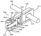
도 9는 척추 10의 척추뼈 속으로 삽입되고, 하나 또는 그 이상의 고정 부재들 2300에 고정되고, 아치 형상을 가질 수 있는 부재들 2200을 도시하는 장치 3000의 실시예를 묘사한다. 부재들 2200은 예를 들어, 업계에서 알려진 표준 고정 클램프들일 수 있는 클램프 2400을 사용하여 고정 부재들 2300에 고정될 수 있다. 각각의 부재 2200에 있는 핸들 2500은 부재들 2200을 삽입 및/또는 조작하는데 사용될 수 있다.FIG. 9 depicts an embodiment of an
도 10은 예를 들어, 필요한 위치에 부재들 2200 및/또는 캐뉼라 2100을 고정하기 위해 세로 방향 부재 2400으로서 사용될 수도 있는 봉 900의 측면도이다. 봉 900은 예를 들어, 클램프 또는 다른 장치(예, 도 11의 클램프 4000)의 일 방향 920 운동을 허용하지만 반대 방향 930으로의 이동을 허용하지 않도록 하기 위하여 톱니(crenate) 모양 또는 스캘럽(scallop) 무늬일 수 있는 리지(ridge) 또는 노치 910을 포함할 수 있다.FIG. 10 is a side view of a
도 11 및 도 12는 예를 들어, 클램프 2400 대신에 봉 900과 함께 사용될 수 있는 선택적으로 결합 가능한 클램프 4000의 측면도를 도시한다. 클램프 4000은 봉 900과 선택적으로 결합하도록 구성된 제1 영역 4100, 및 제1 영역과 결합되고 척추체에 고정될 수 있는 캐뉼라 또는 다른 가늘고 긴 부재와 조절 가능하게 결합하도록 구성된 제2 영역 4200을 구비할 수 있다. 선택적으로 결합 가능한 제1 영역 4100은 예를 들어, 개방단 4111을 가진 하우징 4110 및 하우징 4110 내부에 부분적 으로 위치되어 개방단 4111로부터 확장할 수 있는 내부 본체 4112를 구비할 수 있다. 바이어싱 부재 4120은 하우징 4110 내부의 공간 4150 예를 들어, 내부 본체 4112와 제2 영역 4200의 볼트 4210의 부재 4211 사이에 배치될 수 있다. 바이어싱 부재 4120은 내부 본체 4112를 개구 4111을 통해 밖으로 힘을 가하기 쉬운 바이어스력을 제공할 수 있다.11 and 12 show side views of selectively
하우징 4110에 있는 하나 또는 그 이상의 구멍들 4113은 예를 들어, 내부 부재 4112의 가늘고 긴 개구 4114를 관통할 수 있는 핀 4130을 통과하는 치수일 수 있으므로, 내부 본체는 하우징 4110에 대해 움직일 수 있지만, 하우징 4110 내부에서 핀 4130에 의해 유지될 수 있다. 소켓 4115 또는 구멍 또는 도 12에 도시된 바와 같이, 구멍 4113의 반대편에 위치된 하우징 4110의 다른 특징은 핀 4113을 결합 및 고정하는 구성일 수 있다.One or
하우징 4110은 측면 구멍(미도시)을 구비할 수 있고 내부 본체 4112는 측면 구멍 4117(도 12 참조)을 구비할 수 있다. 구멍들 4116 및 4117은 원형, 타원형, 또는 다른 필요한 모양일 수 있다. 예를 들어, 도 12에 도시된 바와 같이, 내부 본체 4112의 개구 4117은 실질적으로 타원형이다. 내부 본체 4112는 하우징 4110에 대한 버튼(button)으로서 기능 할 수 있다. 예를 들어, 바이어싱 부재의 힘에 대항하여, 내부 본체 4112를 하우징 4110 속으로 미는 것은 구멍들 4116 및 4117을 정렬할 수 있으므로 봉 900은 그 길이를 따라 자유롭게 움직일 수 있다. 버튼이 릴리스 될 때, 바이어싱 부재는 내부 본체 4112를 외측으로 힘을 가할 수 있고, 이것은 구멍들 4116 및 4117의 정렬을 변화시킬 수 있으므로, 예를 들어 봉 900의 노치 910이 구멍 4116 주변의 하우징의 가장자리와 결합하여 적어도 일 방향으로 봉 900에 대한 클램프 4000의 이동을 방지한다. 이러한 메커니즘을 사용하고, 톱날 모양 노치들 910 때문에, 클램프 4000은 일 방향으로 봉 900 위로 미끄러질 수 있지만, 구멍들 4116 및 4117을 정렬하기 위해 내부 본체 4112(예, 버튼)를 하우징 4110 속으로 약화시키지 않고 반대 방향으로 미끄러질 수 없다.The
클램프 4000의 제2 영역 4200은 부재, 예컨대 가늘고 긴 부재 2200 또는 캐뉼라, 봉, 투관침, 유도도관, 와이어, 핀, 또는 척추체 12 속으로 삽입하기 위한 적절한 다른 가늘고 긴 부재, 또는 다른 부착물과 결합 및 고정되도록 구성될 수 있다. 제2 영역 4200은 하우징 4110과 결합된 볼트 4210 또는 스크류, 볼트 4210과 결합된 하나 또는 그 이상의 바이스(vice) 플레이트들 4220,4230, 및 바이어싱 부재 4240에 대향되기 쉽고 부재 2200(미도시) 주위에 바이스 플레이트들 4220,4230을 결속하기 쉬운 너트 4250을 구비할 수 있다. 볼트 4210은 하우징 4110 내부에 위치되고 샤프트 4212에 부착된 부재 4211을 구비할 수 있다. 샤프트 4212의 끝단 4213은 나사산 4214가 형성될 수 있다. The
바이스 플레이트들 4220,4230은 그곳을 통해 볼트 4210가 통과할 수 있는 개구 4221,4231을 각각 가질 수 있다. 이렇게 하여, 바이스 플레이트들 4220,4230은 볼트 4210 위, 예를 들어 너트 4250과 하우징 4110 사이에 고정될 수 있다. 각각의 바이스 플레이트 4220,4230은 부재 2200 또는 다른 가늘고 긴 부재를 결합 및 유지하기 위해 각각 수납 영역 4222,4232를 가질 수 있다.
바이어싱 부재 4240(예, 코일 스프링, 웨이브 와셔, 레이디얼 스프링)은 제1 바이스 플레이트 4230과 하우징 4110 사이에 위치될 수 있다. 이렇게 하여, 너트 4250이 베이스 4210에는 연결되지만 그곳에 완전하게 조여지지 않을 때, 뼈 연결 요소는 예를 들어, 뼈 연결 요소를 수납 영역들에 삽입함에 의해 바이스 플레이트들 4220,4230 사이에 클립 또는 스냅 결합될 수 있다. 그러한 구성은 뼈 구성 요소가 바이스 플레이트들 4220,4230 사이 예를 들어, 너트 4250 앞에 임시적으로 유지되는 것을 허용할 수 있다.A biasing member 4240 (eg, coil spring, wave washer, radial spring) may be located between the
또한, 바이스 플레이트들 4220,4230은 바이스 플레이트들의 적절한 정렬을 용이하게 하는 특징을 가진다. 예를 들어, 제2 바이스 플레이트 4230은 그곳으로부터 확장하고, 제1 바이스 플레이트 4220의 적어도 하나의 리세스(미도시)에 수납될 수 있는 적어도 하나의 돌기(미도시)를 가질 수 있다. 이러한 방식에 있어서, 바이스 플레이트들 4220,4230 모두는 수납 영역들 4222,4232 쪽으로 향하기 위해 함께 회전할 수 있다. 다양한 다른 핀, 돌기, 만입, 커플러 또는 다른 정렬 특징들이 사용될 수도 있음을 이해할 것이다.
너트 4250을 조이기 위하여, 너트 4250은 너트 4250의 수동-조임을 용이하게 할 수 있는 파지부 4251(예, 톱니 모양, 우툴두툴함)을 가질 수 있다. 대안적으로 또는 그에 부가하여, 렌치 또는 다른 도구의 결합을 용이하게 하는 다른 특징들이 너트 4250 위에 마련될 수 있다. 당업자들은 다른 클램프들 또한 도시되고 설명된 다른 외부 고정 시스템과 함께 사용될 수 있음을 이해할 것이다.To tighten the
도 13a 및 도 13b는 하나 또는 그 이상의 클램프들 4000과 결합할 수 있는 노치 910 또는 다른 특징들을 가진 봉 900을 도시하는 개략도들이다. 클램프들 4000은 노치 특징들 910과 결합할 수 있고 예를 들어, 노치 특징들 910의 방향에 따라 특정한 방향으로 봉 900을 따라 이동할 수 있다. 13A and 13B are schematic diagrams illustrating a
두 개의 봉 900은 컨넥터 950에 의해 함께 부착될 수 있으므로, 노치들 910-1 및 910-2의 방향은 반대 방향이다. 따라서, 정복 즉, 클램프들의 이동은 도 14의 화살표 2710 및 2720에 의해 표시된 바와 같이 반대 방향으로 일어날 수 있다.The two
도 5, 도 6 및 도 14에 도시된 바와 같이 고정 장치 3000을 사용하여 척추를 더 돌리고/움직이기 위해서, 예를 들어, 조절 가능한 글라이딩 메커니즘 3500(도 17 및 도 18)을 사용하여, 가늘고 긴 부재들 2200을 서로 교차시키는 것이 필요할 수 있다(도 15 및 도 16). 도 15 및 도 16은 가늘고 긴 부재들 2200에 연결된 조절 가능한 글라이딩 머케니즘 3500을 도시한다. In order to further rotate / move the spine using the
도 17 및 도 18은 유사하게 기능하는 조절 가능한 글라이딩 메커니즘 3500의 두 개의 실시예들을 도시한다. 도 17에 도시된 조절 가능한 글라이딩 메커니즘 3500은 "I-bar" 구성을 가질 수 있는 슬라이딩 가능한 부재 3510을 구비하고, 여기서 수직 부재 3511은 포지션 부재들 3520,3530이 슬라이딩 가능한 부재 3510의 전장을 따라 움직이는 것을 허용하기 위해 양 측면에 있는 노치들 3512를 가진다. 포지션 부재들 3520,3530은 슬라이딩 가능한 부재 3510의 수평 부재들 3513,3514 사이에 고정되어 수직 부재 3511과 짝을 맞춘다. 각각의 포지션 부재 3520,3530은 돌기들, 또는 슬라이딩 가능한 부재 3510에 있는 노치 3512와 상응하는 짝이 되는 측면 3523,3533에 있는 다른 수단 3524를 가질 수 있다. 포지션 부재들 3520,3530은 또한 릴리스 버튼 3522,3532를 포함할 수 있고, 예를 들어, 버튼을 낮춤에 의해 작 동시킬 때, 포지션 부재들 3520,3530은 슬라이딩 가능한 부재 3510을 따라 움직일 수 있다. 즉, 예를 들어, 돌기들 3524가 노치들 3512로부터 풀리면 포지션 부재들 3520,3530은 슬라이딩 가능한 부재 3510의 전장을 따라 수평 부재들 3513,3514 사이에서 미끄러질 수 있다. 포지션 부재들 3520,3530은 예를 들어, 각각의 수평 부재로부터 확장하는 립(lip)(미도시)에 의해 수평 부재들 3513,3514 사이에 유지될 수 있다. 각각의 포지션 부재 3520,3530은 가늘고 긴 부재들 2200이 포지션 부재들 3520,3530에 부착되는 것을 허용하는 부착 유니트 3521,3531을 가질 수 있다. 부착 유니트 3521,3531은 가늘고 긴 부재들 2200의 각도를 조절하기 위해 회전될 수 있으므로, 그들은 서로에 대해 교차할 수 있다. 17 and 18 show two embodiments of an
도 18은 조절 가능한 글라이딩 메커니즘 3500의 슬라이딩 가능한 부재 3550의 대안적 실시예를 도시한다. 이 실시예에 있어서, 슬라이딩 가능한 부재 3550은 서로 평행한 두 개의 트랙들 3551,3552를 가진다. 각각의 트랙 3551,3552는 치차 3553 또는 포지션 부재들 3520,3530의 증가적 이동을 허용하기 위한 다른 수단을 가질 수 있다. 부착 유니트들 3521,3531 및 릴리스 버튼들 3522,3532를 가진 포지션 부재들 3520,3530은 전술한 실시예와 같이 유사하게 기능한다.18 shows an alternative embodiment of the
도 19는 척추뼈 정복을 위한 대안적 장치를 도시한다. 전술한 바 있는 고정 장치 3000 대신에, 척추뼈로부터 확장하는 가늘고 긴 부재 2200은 그들의 근위단 2220에 부착된 벨크로 파스너 3600을 가질 수 있다. 예를 들어, 가늘고 긴 부재들 2200을 수동적으로 조작 및 제어함에 의해, 척추 전만증을 복구하기 위해 가늘고 긴 부재들 2200을 조작한 후, 서로에 대한 가늘고 긴 부재들 2200의 위치들은 벨크 로 파스너 3600이 장착된 가늘고 긴 부재들에 달라붙음으로써 고정될 수 있다. 벨크로 파스너 3600은 가늘고 긴 부재들 2200의 핸들 2500 위에 직접 부착될 수도 있고 아니면 다른 캡(미도시)이 핸들 위로 미끄러질 수도 있다. 벨크로 파스너 3600을 핸들 2500에 부착하기 위한 다른 방법들이 강구될 수 있다.19 shows an alternative device for vertebral conquest. Instead of the
척추 세그먼트가 긴장이 풀리고 정복되면, 골절된 척추체는 수술 치료될 수 있다.Once the spinal segment is relaxed and conquered, the fractured vertebral body can be surgically treated.
치유된 골절의 분쇄(Crushing the Healed Fracture DisruptDisrupt HealedHealed FractureFracture )(단계 1300)) (Step 1300)
골절된 척추체 12b의 영역에 있는 척추뼈 12a 및/또는 12c의 정복 전 또는 후에, 붕괴된 척추체 12b의 전방 영역 22, 및 특히 피질 쉘(shell) 14는 재-골절시키거나, 분리시키거나 아니면 분쇄시킬 필요가 있을 수 있다. 그러한 시술은 예를 들어, 골절된 뼈가 예컨대, 6주 또는 그 이상의 기간을 넘어 치유되었거나 부분적으로 치유된 경우들에 척추뼈 종판들 20 및 30의 정복 및/또는 증대를 위해 척추체를 준비하는데 특히 유용할 수 있다. 다양한 형태의 분쇄 장치들은 예를 들어, 도 20에 도시된 바와 같은 끌(chisel) 800, 레이저 900, 다른 도구와 같이 손상된 피질 뼈 14를 골절시키는데 사용될 수 있다.Before or after the reduction of
도 20은 뼈 또는 다른 단단한 구조물들을 분해하도록 구성될 수 있는 근위 팁 5420을 가진 가늘고 긴 부재 5410을 구비할 수 있는 분쇄 장치 또는 끌-유사 장치 5000을 도시한다. 가늘고 긴 부재 5410은 다른 모양들도 생각해 볼 수 있지만 대략 원통형일 수 있다. 팁 5420은 여기서 설명된 바와 같이 다양한 모양을 가질 수 있으며, 예를 들어, 팁 5420은 도 20에 도시된 바와 같이, 뼈를 분쇄하기 위한 칼-모양의 팁을 제공하기 위해 테이퍼 질 수 있다. 팁 5420은 또한 주변의 조직의 손상을 최소화하기 위해 적어도 부분적으로 뭉툭할 수 있다. 핸들 5430 가늘고 긴 부재 5410의 원위단 5432 예컨대, 반대되는 팁 5420에 부착될 수 있다.20 illustrates a grinding device or chisel-
도 20에 도시된 바와 같이, 분쇄 장치 5000은 예를 들어, 캐뉼라 5440을 통해 후방 접근법을 사용하여 척추뼈 속으로 삽입될 수 있으므로, 팁 5420은 척추체 12의 중앙 영역 50을 관통하여 척추뼈 12의 전방 측면 22 위의 피질 뼈 14와 접촉할 수 있다. 캐뉼라 5440은 전술한 캐뉼라들과 유사할 수도 그렇지 않을 수도 있다.As shown in FIG. 20, the grinding
어떤 실시예들에 있어서, 캐뉼라 5440은 척추경 24의 구멍 속으로 나사결합될 수 있는 강성 부재 5442, 및 원통형일 수 있고 장치 5000가 최소 침습적으로 척추체 속으로 접근하도록 척추뼈와 주변의 연약한 조직의 밖으로 확장하는 치수일 수 있는 가늘고 긴 부재 5444를 구비한다. 가늘고 긴 부재 5444는 유연할 수 있고 예컨대, 커플링 5446에서 강성 부재 5442에 영구적으로 연결되거나 분리 가능하게 연결되는 것과 같이 연결될 수 있다. 강성 부재 5442는 척추뼈 속으로, 예컨대 후방 접근으로부터 척추경 24를 통하여 척추체 12의 중앙 영역 속으로의 삽입을 위해 구성될 수 있다. 어떤 실시예들에 있어서, 구멍은 예컨대, 드릴, 투관침, 또는 다른 도구에 의해 예컨대, 척추경 24를 통해 척추뼈 12의 외측 피질 뼈를 통하여 형성될 수 있다. 강성 부재 5442가 부재 5444와 결합하는 곳의 커플링 5446은 척추뼈 12의 척추경 24의 내부 또는 외부의 위치일 수 있다. 다른 실시예들에 있어서, 다 른 형태의 캐뉼라들, 투관침, 또는 다른 안내도관은 척추뼈 12 또는 다른 뼈에 분쇄 장치 5000을 위한 접근을 제공하는데 사용될 수 있다.In some embodiments,
장치 5000의 부재 5410의 직경은 예를 들어, 약 2mm와 10mm 사이일 수 있다. 장치의 부재 5410은 예를 들어 약 20cm와 70cm 사이의 그 어떤 필요한 길이를 가질 수 있다. 핸들 5430은 예를 들어, 약 4cm와 20cm 사이의 그 어떤 필요한 길이를 가질 수 있다. 장치 5000은 스테인리스 스틸, 금속, 금속 합금, 폴리머, 복합재료, 세라믹 또는 그들의 결합을 구비할 수 있다. The diameter of the
가늘고 긴 부재 5410은 슬리브 5422 또는 부재 5410의 주위에 배치되고/또는 거기에 부착된 다른 장치 또는 부재를 포함할 수 있고, 슬리브 5422는 예를 들어, 아래에서 더 상세히 설명되는 바와 같이, 커플러 5446과의 접촉에 의해 척추체 12 속으로의 부재 5410의 축방향 이동의 양을 제한하는 치수일 수 있다. The
도 21에 도시된 바와 같이, 한 개, 두 개 또는 그 이상의 분쇄 장치들, 예, 5000-1 및 5000-2는 도 20과 관련하여 설명된 바와 같이 예를 들어 하나 또는 그 이상의 캐뉼라들 5440을 통해 척추체 12 속으로 삽입될 수 있다. 캐뉼라들 5440은 강성 부재 5442를 가질 수 있고, 강성 부재 5442는 도시된 바와 같이 예컨대, 척추경들 24를 통하여 척추뼈에 고정하기 위한 나사산 5443을 포함할 수 있다. 어떤 실시예들에 있어서, 강성 부재 5442는 렌치 또는 강성 부재 5442를 뼈 12 속으로 스크류 결합 및/또는 아니면 고정하기 위한 다른 도구와 결합하도록 구성될 수 있는 실질적으로 편평한 면 또는 다른 표면들을 가진 너트 특성 5447을 포함할 수 있다. 커플링 5446은 예컨대, 부재 5444와 강성 부재 5442 사이에 탈착 가능한 연결을 제 공할 수 있다.As shown in FIG. 21, one, two or more grinding devices, for example, 5000-1 and 5000-2, for example, may have one or
장치 5000은 예를 들어, 도 21의 장치 5000-1 및 5000-2에 의해 도시된 바와 같이 다른 구성들을 가질 수 있다. 장치 5000-1은 상대적으로 균일한 직경을 가진 가늘고 긴 부재 5410-1과 함께 도시된다. 그러한 실시예들에 있어서, 부재 5410-1은 예를 들어 척추체의 전방 끝단 22에서 피질 뼈 14 쪽으로, 캐뉼라를 통해 축방향으로 자유롭게 움직일 수 있다. 다른 실시예들에 있어서, 그러한 예를 들어, 장치 5000-2, 부재 5410-2는 멈춤 장치 5512 또는 캐뉼라 5440 내부에서 부재 5410-2의 축 방향 이동을 제한하는 다른 특징을 포함할 수 있다. 예를 들어, 부재 5410-2는 척추뼈 12의 전방 측면 22 쪽으로 근위적으로 움직이고, 멈춤 장치 5512는 커플러 5446의 가장 자리 5510과 접촉할 수 있으므로, 척추체 속으로 부재 5410-2의 추가적 이동을 방해 또는 방지한다. 멈춤 장치 5512는 예를 들어, 부재 5410-2의 일부분을 둘러싸는 슬리브 5422에 의해 제공될 수 있고, 척추체 12 속으로의 부재 5410-2의 축 방향 이동의 필요한 범위를 제공하기 위해 치수화되고/또는 조절 가능하게 될 수 있다.
도 22a 및 도 22b는 팁들 5420, 예, 팁 5420-1 및 5420-2를 확대하여 도시한다. 팁 5420은 예를 들어, 척추뼈 압박 골절의 결과로서 상해 후, 붕괴된 상태에서 예컨대, 뼈 14가 치유된 후, 척추뼈 12의 피골 뼈 14를 예를 들어, 자르거나, 부수거나, 아니면 분쇄하는 그 어떤 필요한 구성을 가질 수 있다. 팁 5420은 하나 또는 그 이상의 치수로 테이퍼질 수 있고, 예를 들어, 팁 5420-1에 의해 도시된 바와 같이 칼 또는 끌-모양의 팁을 제공하도록 테이퍼질 수 있다. 다른 실시예들에 있어 서, 팁 5420은 팁 5420-2에 의해 도시된 바와 같이 예를 들어, 물갈퀴(paddle)-모양의 구성과 같은 다른 구성을 가질 수 있으며, 여기서, 팁은 부재 5410-2의 직경 보다 더 큰 폭을 가질 수 있다. 팁 5420 및/또는 부재 5410 구성들과 관련된 부가적인 상세한 설명은 예를 들어, 도 28 내지 도 30과 관련하여 설명한 것처럼, 본 명세서의 다른 곳에서 설명된다. 22A and 22B show enlarged views of
도 23은 척추경 24를 통해 캐뉼라 5440을 삽입하기 위해 예를 들어, 핸들 5710을 가진 도구 5700을 사용하여, 척추뼈 12의 후방 측면 속으로 삽입되어 있는 캐뉼라 5440 또는 다른 안내도관들과 함께 척추의 사시도를 도시한다. 다양한 형태의 캐뉼라는 척추뼈 12 속으로 장치들 5400의 통로를 제공하는데 적합할 수 있다.FIG. 23 illustrates the spine with
도 24는 전술한 바와 같은 캐뉼라 5440과 함께 사용될 수도 그렇지 않을 수도 있는 분쇄 장치 5000의 단면도를 도시한다. 분쇄 장치 5000은 캐뉼라 5440을 통해, 예컨대, 강성 부재 5442와 부재 5444를 통해 관통하도록 구성된 가늘고 긴 부재 5410을 포함할 수 있다. 슬리브 5422 또는 다른 부재는 부재 5410 주위에 배치될 수 있고, 장치 5000이 척추체 또는 다른 뼈 속으로 축방향으로 전진할 때 슬리브 5422의 끝단 5512가 강성 부재 5442의 커플러 5446와 근위단 5510과 결합할 수 있도록 치수화 및/또는 위치된다. 슬리브 5422는 예를 들어, 척추뼈 속으로 장치 5000의 운동의 필요한 범위를 제공하기 위해, 부재 5410에 부착될 수도 있고/또는 그 위에 슬라이딩 가능하거나 조절 가능할 수도 있다. FIG. 24 shows a cross-sectional view of the grinding
부재 5410의 근위단 5432는 예를 들어, 도 26과 관련하여 더 상세히 설명된 바와 같이, 핸들 5430에 결합이 요구되는 바와 같이 구성될 수 있다. The
도 25는 척추뼈 12에 사용시 분쇄 장치 5000의 다른 측면도이다. 가늘고 긴 부재 5410, 팁 5420 및 캐뉼라 5440은 전술한 바와 같을 수 있다. 이 예에 있어서, 슬리브 5422는 캐뉼라 5410의 내부에 고정되게 구성될 수 있다. 슬리브 5422는 외측으로 확장되어 부재 5410의 장축을 따라 세로 방향으로 뻗을 수 있는 돌기들 5433을 포함할 수 있다. 그러한 돌기들 5443은 장치 5410가 캐뉼라 5440 및 척추뼈 12의 공간 50을 통해 뼈 12 쪽으로 밀려질 때 예컨대, 임플란트 5440의 강성 영역 5442의 원위단과 접촉함에 의해 장치 5000을 위한 한계 멈춤을 제공을 위해 유용할 수 있다. 25 is another side view of the grinding
도 26은 뼈 14에 접촉되어 그것을 분쇄하기 위해 캐뉼라 5440을 통해 척추뼈 12 속으로 삽입된 팁 5420을 가진 분쇄 장치 5000의 평면도이다. 장치 5000은 척추뼈 12의 전방 영역에서 피질 뼈 14 속으로 팁 5420의 침투 깊이(T)를 제한 또는 제어하기 위한 슬리브 5422 또는 다른 메커니즘을 포함할 수 있다. 가늘고 긴 부재 5410의 원위단 5432는 예를 들어 소켓 5434 내부에서 핸들 5430에 고정 또는 결합될 수 있다. 어떤 실시예들에 있어서, 슬리브 5422는 소켓 5434에서 끝단 5432와 접촉할 수 있다. 소켓 5434와 끝단 5432는 서로 분리가능하게, 조절 가능하게, 고정되게 연결되도록 구성될 수 있다. 예를 들어, 소켓 5434는 나사가 형성될 수 있고 끝단 5432는 상응하는 나사산을 가질 수 있으므로, 예를 들어, 장치의 침투 깊이(T)는 끝단 5432가 핸들 5430의 소켓 5434 내부에 배치된 양을 조절함에 의해 조절될 수 있다. FIG. 26 is a top view of the grinding
도 27은 붕괴되거나 골절된 위치에서 치료가 완료될 수 있는 뼈를 해체하기 위해 척추뼈에 사용하기 위한 분쇄 장치 5000의 측면도이다. 장치 5000은 전술한 바와 같은 슬리브 5422를 구비하고, 슬리브는 뼈 14를 통하여 팁 5410의 이동을 제한하는 기능을 할 수 있다. 그러한 제한은 예를 들어, 해체될 영역을 둘러싸고 있는 조직들이 허약하거나 예민할 수 있는 경우에 바람직할 수 있다. 화살표 1은 손상될 수 있고 분쇄될 수 있으며 본 명세서에 설명된 방법들을 사용하여 나중에 잠정적으로 치유될 수 있는 뼈 14의 영역을 도시한다. FIG. 27 is a side view of a
도 28에 도시된 바와 같이, 장치 5000의 끝단은 예를 들어, 뼈와의 접촉을 위해 팁이 날카롭게, 반-날카롭게, 또는 뭉툭하게 구성된 팁 5420을 사용하여, 예컨대, 장치 5000을 척추뼈 12의 전방 영역 속으로 전진시키기 위한 햄머 2를 사용하여 척추뼈 12 속으로 삽입될 수 있다. 즉, 장치 5000은 예를 들어, 햄머 2를 사용하여 뼈에 대항하여 충격을 받을 수 있다. 다른 실시예들에 있어서, 진동기 또는 다른 장치는 예를 들어, 핸들 5430 및/또는 가늘고 긴 부재 5410에 부착되어, 가늘고 긴 부재들 5410을 예를 들어, 세로 방향, 가로 방향 및/또는 다른 방향으로 척추뼈 12 속으로 손상된 뼈를 향해 움직이도록 사용될 수 있다.As shown in FIG. 28, the end of the
도 29는 척추뼈 12와 가늘고 긴 부재 5410 및 팁 5420을 가진 장치 5000의 확대된 측면을 도시하고 장치 5000에 의해 가능해지는 운동들, 가로방향 운동 3 및 세로 방향 운동 4를 도시한다.FIG. 29 shows an enlarged side view of the
도 30a 내지 도 30c는 뼈를 분쇄하는데 사용될 수 있는 다양한 팀들 1512,1522,1532의 예들을 개략적으로 도시한다. 도 31은 부재 5420-1 및 팁 5420-2의 확대 평면도들을 도시한다. 도 31a 및 도 31b는 척추체에 사용하기 위한 장치 5410-2의 평면도들을 도시한다. 도 32a 및 도 32b는 다른 형태의 팁들 1720 및 1722의 확대도들이다.30A-30C schematically illustrate examples of
도 33에 도시된 바와 같이, 뼈를 절단 또는 골절시키기 위한 레이저 9000 또는 다른 도구는 척추체 12bdml 손상된 피질 뼈 14(도 34)를 파괴 또는 분쇄하는 끌 또는 다른 분쇄 장치 5000 대신에 또는 이에 부가하여 사용될 수 있다. 레이저 9000은 캐뉼라 2100을 관통하여 척추뼈 12b의 내부 영역 50 속으로 통과하도록 구성될 수 있다. As shown in FIG. 33, a
도 35는 예를 들어, 분쇄 장치 5000 또는 레이저 9000을 사용하여 재-골절된 피질 뼈 14를 가진 척추체 12b의 개략도이다. 분쇄 장치 5000 또는 레이저 9000은 예를 들어, 척추체 12b의 높이를 복원하기 위해 종판들 20 및 30의 정복을 위한 준비에서 캐뉼라 2100으로부터 제거되었다.35 is a schematic diagram of
척추체 높이 복원(단계 1400)Vertebral Height Restoration (Step 1400)
도 1의 단계 1300에서 척추체 12b의 피질 뼈 14를 재-골절 또는 아니면 분쇄시킨 후, 척추체 12b의 높이 또는 종판들 20 및 30 사이의 거리는 정상적인 높이(예, 상해 전의 척추체 12b의 높이)까지 증가될 수 있다. After re-fracture or otherwise comminute the
척추체 높이의 복원 방법의 예가 도 35a 내지 도 35d에 더 상세히 도시되어 있다. 예를 들어, 도 35a는 척추체 12b속으로 삽입된 부분적으로 유연한 캐뉼라 6000을 도시한다. 나중에 설명되는 캐뉼라 100와 동일하거나 유사하게 되어 있는, 캐뉼라 6000은 예를 들어 근위 부재 6100 및 원위 부재 6200을 구비할 수 있다. 강 성 캐뉼라, 바늘, 투관침 또는 다른 안내도관 6500은 캐뉼라 6000의 배치를 용이하게 하는데 사용될 수 있다. 예를 들어, 캐뉼라 6000의 관 6300 내부에 맞도록 치수를 가질 수 있는 안내도관 6500은 당업자에 의해 알려진 바와 같이 먼저 척추경을 통해 척추체 속으로 삽입될 수 있다. 그 후, 캐뉼라 6000은 안내도관 6500 위로 미끄러져 위치됨으로써 원위 부재 6200은 척추경 24를 관통하여 척추체 12b의 중앙 영역 50에 도달할 수 있다. An example of a method of restoring vertebral height is shown in more detail in FIGS. 35A-35D. For example, FIG. 35A shows a partially
근위 부재 6100은 근위 부재 6200에 부착 또는 결합되어 환자의 예를 들어, 피부 및 근육과 같은 연약한 조직을 통해 척추로부터 후방으로 확장할 수 있다. 굴곡 도구들의 삽입을 허용하고 척추경 24 및 주변의 유연한 조직에 상처를 최소화 하는 것을 돕기 위해, 근위단 6100은 휠 수 있거나 반-휠 수 있다.The
캐뉼라 6000의 삽입 후, 안내도관 6500은 도 35b의 단계에 도시된 바와 같이, 예컨대, 굴곡 봉 6700 또는 다른 도구, 임플란트 또는 충진재의 척추체의 중앙 영역 속으로의 삽입을 위한 통로를 제공하기 위해 캐뉼라 6000의 관 6300을 개방하기 위해 제거될 수 있다. After insertion of the
도 35c에 도시된 바와 같이, 손상된 척추체의 붕괴된 종판들의 정복을 위한 도구는 그 후 캐뉼라 6000을 통해 삽입될 수 있다. 예를 들어, 굴곡될 수 있고 헤드 6750을 가질 수 있는 봉 6700은 관 6300을 통해 삽입될 수 있고 상부 종판 20에 대항하여 미는데 사용될 수 있다. 봉 1130은 도 35c에 도시된 바와 같이 척추체 12b의 중앙 영역 속으로 전진할 수 있고, 굴곡된 봉 6700은 종판들 20 및 30을 밀어서 분리시켜 척추체 12b의 높이를, 예를 들어 도 35c의 높이 h1로부터 도 35d의 높이 h2까지 복원할 수 있다. 봉 6700은 도 35c 및 도 35d에 설명된 것과 다르게 구성될 수 있고 하나 보다 많은 조각 또는 요소를 구비할 수 있고 관절 운동하는 조각들을 구비할 수 있다. As shown in FIG. 35C, a tool for conquest of the collapsed end plates of the injured vertebral body may then be inserted through the
보다 더 상세히, 척추뼈 증대 장치의 일 실시예는 캐뉼라를 제공한다. 도 36은 강성 부재 110 및 유연성 부재 120을 구비할 수 있는 부분적으로 유연한 캐뉼라 100을 도시한다. 유연성 부재 120은 커플링/조인트 130에서 강성 부재 110에 예컨대, 영구적으로 연결되거나 분리가능하게 연결될 수 있다. 강성 부재 110은 척추뼈 속으로, 예컨대 후방 접근으로부터 척추경 24를 통하여 척추체 12의 중앙 영역 50 속으로 삽입을 위해 구성될 수 있다. 어떤 실시예에 있어서, 구멍 60은 척추뼈 12의 외부 피질 뼈를 통하여 예컨대, 척추경 24를 통하여, 예컨대 드릴, 투관침, 또는 다른 도구에 의해 형성될 수 있다. 강성 부재 110가 유연성 부재 120과 결합하는 곳의 조인트 130은 척추체 12의 척추경의 내부 또는 외부 위치일 수 있다.In more detail, one embodiment of a vertebral augmentation device provides a cannula. 36 illustrates a partially
캐뉼라 100은 강성 부재 110과 유연성 부재 120을 통하는 통로를 형성할 수 있는 관 140(예, 도 38 및 도 42의 관 140 참조)을 가질 수 있다. 관 140은 임플란트, 안내도관, 도구, 뼈 충진재 또는 다른 물질을 척추뼈의 중앙 영역 속으로 삽입하는데 사용될 수 있다. 예컨대, 굴곡 유연성 부재들 120-b에 의해 설명된 바와 같이, 유연성 부재 120의 상대적 유연성은 다양한 임플란트, 도구, 뼈 충진재 또는 다른 물질의 삽입 또는 조작 동안 척추경 및/또는 주변 조직에 손상을 최소화 또는 방지하는 것을 도울 수 있다. 유연성 부재는 일반적으로 위치되어 예를 들어, 피부 및 근육과 같이 환자의 유연한 조직을 통하는 통로를 제공한다.
도 36에 도시된 바와 같이, 한 개, 두 개 또는 그 이상의 캐뉼라 100은 척추체 12 속으로 삽입 또는 이식될 수 있다. 두 개의 캐뉼라가 사용되는 경우, 모든 캐뉼라 100은 도구, 임플란트 및/또는 뼈 충진재를 척추뼈 12의 내부 50으로 도입하는데 사용될 수 있다. 캐뉼라 100의 외경은 예를 들어, 약 3mm와 12mm 사이일 수 있고, 내경은 약 2mm와 10mm 사이일 수 있다. 캐뉼라 100은 스테인리스 스틸, 금속, 금속 합금, 폴리머, 복합재료, 세라믹 또는 그들의 조합의 그 어떤 것을 구비할 수 있다. As shown in FIG. 36, one, two or more cannula 100 may be inserted or implanted into
도 37은 척추뼈 12의 척추경 24를 통해 삽입된 도 36의 캐뉼라 100의 어느 하나의 확대도를 제공한다. 구체적으로, 강성 부재 110은 척추뼈 12의 척추경을 통해 삽입된 것으로 도시되어 있다. 강성 부재 110은 척추뼈 12의 후방 측면의 바로 외측의 커플링 130에서 유연성 부재 120과 연결될 수 있다. 강성 부재 110은 나사산 112 또는 마루(ridge) 또는 예컨대, 척추뼈 12를 통하여 강성 부재 110의 삽입을 용이하게 할 수 있는 다른 특징들을 포함할 수 있다. 강성 부재 110은 뼈를 통과하는 천공(boring)을 용이하게 하기 위해 나사산 112와 함께 작동할 수도 그렇지 않을 수도 있는 날카롭게 되어 있고, 주름 잡히고/또는 톱니가 형성된 끝단 111을 더 포함할 수 있다.FIG. 37 provides an enlarged view of any one of the
도 38 및 도 39는 캐뉼라 100의 부가적인 상세한 설명을 도시한다. 어떤 실시예들에 있어서, 강성 부재 110은 척추경 24의 폭과 거의 동일한 길이를 가진 샤프트부 113을 가질 수 있으므로, 강성 부재 110은 예컨대, 척추경으로부터 후방으로 확장하는 강성 부재의 작은 부분만으로도 척추경 24 내부에 완전히 이식될 수 있다. 도 38의 단면도에 도시된 바와 같이, 강성 부재 110과 유연성 부재 120 각각은 관 115 및 125를 각각 한정하는 내경과 외경을 가진 실질적으로 원통형인 벽 114 및 124를 가질 수 있다. 관 115 및 125는 예를 들어 커플링 130에서 결합되어, 전체 캐뉼라 100을 통하여 관 130을 형성할 수 있다.38 and 39 show additional details of the
강성 부재 110은 나사산 112를 포함할 수도 그렇지 않을 수도 있는 샤프트 또는 튜브 113을 구비할 수 있다. 근위단 111은 튜브 113의 끝단으로부터 연장하는 톱니 116 또는 다른 절단 특징들로 구성될 수 있다. 캐뉼라 100의 커플링 130은 강성 부재 110과 유연성 부재 120을 분리 가능하게 또는 영구적으로 연결할 수 있다. 예를 들어, 도 38에 도시된 바와 같이, 커플링 130은 유연성 부재 120의 관 125 내부에 꼭 맞는 슬립 피팅 131을 포함할 수 있고 유연성 부재 120을 강성 부재 110에 고정한다. 커플링 130 위의 멈춤 장치 132는 유연성 부재 120과 강성 부재 110의 커플링을 위한 경계 및/또는 밀봉을 제공할 수 있다. 멈춤 장치 132는 실질적으로 편평한 표면들 133 또는 예컨대, 렌치 또는 강성 부재 110을 뼈 12에 스크류 결합 및/또는 고정하기 위한 다른 장치와 같은 도구와 결합하도록 구성될 수 있는 다른 특징들을 포함할 수 있다. 커플링 130은 유연성 부재 및/또는 강성 부재 사이에 분리 가능한 커플링을 제공할 수 있다.
도 39를 참조하면, 캐뉼라 100의 다른 실시예는 강성 부재 110과 유연성 부재 120을 포함할 수 있다. 그러나, 부재 120이 강성 부재 110으로부터 분리되고 강성 부재 110가 유연성 부재 120으로부터 분리되는 것을 허용하는 커플링 130에 의해 연결되지 않고, 단일-피스 캐뉼라 200으로서 형성될 수 있다. 그러한 실시예에 있어서, 커플링 또는 조인트 210은 캐뉼라의 유연성 또는 제어된 굴곡을 제공하는 마루 215 또는 다른 특징들을 포함할 수 있다. 더 상세하게, 부재 120은 강성 부재 110과 유사하게 단단할 수도 있지만 단단한 부재 110 및 120 사이의 유연한 조인트 210을 가진다. 부재 120은 다른 실시예에서 제공된 바와 같은 강성 부재 110과 비교하여 상대적으로 유연할 수 있다. Referring to FIG. 39, another embodiment of the
도 40은 예컨대, 척추경 24에 있는 구멍 60과 같은 접근 구멍을 통해 삽입된 캐뉼라 100의 강성 부재 110 영역을 도시한다. 강성 부재 110의 길이는 강성 부재 110이 삽입되는 척추경 24의 길이와 대체로 상응할 수 있다. 하나 또는 그 이상의 도구들 810,820은 캐뉼라 100을 통해 척추체 12의 내부 영역 50 속으로 삽입될 수 있다. 도구들은 도구 810과 같이 실질적으로 직선일 수 있고, 아니면 도구 820과 같이 굴곡될 수도 있다. 캐뉼라 100의 유연성 영역 120(도구들 810 및 820의 도시의 편의성을 위해 도 40에 미도시)은 굴곡되거나 굽은 임플란트 또는 도구들이 캐뉼라 100 및 척추경 24를 통하여 척추뼈 12의 내부 영역 50 속으로의 삽입을 허용한다. 캐뉼라 100을 통해 삽입된 굴곡된 임플란트 또는 도구들 820의 작동 범위 830은 직선의 임플란트 또는 도구 810보다 클 수 있다.40 shows the
도 41a 및 도 41b는 강성 부재 310 및 312와 함께 굴곡된 도구 300 및 302의 각각의 사용의 예를 설명한다. 강성 부재들 310 및 312는 전술한 바와 같은 강성 부재 110과 유사할 수 있고, 강성 부재의 길이와 강성 부재를 통해 삽입될 수 있는 도구 또는 봉의 곡률 사이의 관계를 설명하기 위해 여기서 별도로 정의된다. 강성 부재들 310 및 312는 전술한 바와 같이 유연성 부재 120과 연결될 수 있지만, 그러 한 유연성 부재들 120은 설명의 명확성을 위해 도시되지 않는다. 도 41b의 강성 부재 312는 도 41a의 강성 부재 310 보다 실질적으로 더 짧다. 설명된 바와 같이, 강성 부재 312는 보다 긴 강성 부재 310에 의해 수용될 수 있는 것보다 더 큰 곡률을 가진 도구 302를 수용할 수 있다. 따라서, 캐뉼라 100과 함께 사용될 수 있는 도구 또는 임플란트의 곡률의 양은, 적어도 부분적으로, 강성 부재 310,312(및 110)의 길이, 강성 부재의 직경 및 도구 또는 임플란트 샤프트의 직경에 의존할 수 있다.41A and 41B illustrate examples of the use of
도 42a 및 도 42b를 참조하면, 굴곡 봉 500은 부분적으로 유연한 캐뉼라 100을 통해 맞춰지는데 필요한 직경과 곡률을 가지도록 구성되고, 붕괴된 척추뼈 12에서 척추 높이를 복원하는데 사용될 수 있다. 봉 500은 캐뉼라 100 내부로 삽입되고, 유연한 부재 120은 봉 500과 함께 휘어질 수 있고 강성 부분 110은 척추뼈 12 내부에서 봉 500의 이동을 규제 및 제한하는 기능을 한다. 어떤 실시예들에 있어서, 봉의 근위단은 척추체 12의 중앙 영역 50 속으로 들어가 척추체 12의 상부 종판 20과 결합할 수 있는 구(bulb) 또는 볼 510을 포함할 수 있다. 벌브 510은 봉 500의 끝단을 뭉툭하게 하여 보다 큰 영역으로 압력을 분산하는 기능을 할 수 있다. 봉 500이 전진할 때, 도 42b에 도시된 바와 같이, 봉 500의 끝단 510은 종판 20에 맞대어 밀고 상부 종판 20과 하부 종판 30 사이의 척추체의 높이를 증가시킬 수 있다. 벌브 510과 함께 또는 그것이 없이, 봉 500의 끝단은, 속이 빈 공간 즉 공동을 형성하기 위해 척추체의 망상 조직 뼈를 압축할 수 있다. 42A and 42B, the
어떤 실시예들에 있어서, 봉 500, 또는 봉 500의 부분은 척추체 높이를 복원한 후 제자리에 남아 있으며, 결과적으로 척추 전만증을 복원하여 척추체를 증대시 킨다. 예를 들어, 봉 500, 예 510의 하나 또는 그 이상의 부분들은 봉 500의 나머지로부터 선택적으로 분리되어, 척추체 12를 증대시키기 위해 중앙 영역 50 내부에 남아 있는 임플란트로서 기능할 수 있다. 다른 실시예들에 있어서, 부가적 도구들, 임플란트들, 뼈 칩들, 뼈 시멘트 및/또는 다른 충진재 물질들은 척추체 높이를 증대 및/또는 맞추기 위해 봉 500 및/또는 캐뉼라 100과 함께 사용될 수 있다.In some embodiments,
척추체를 정복하기 위해 캐뉼라 100 및 봉 500과 같은 도구를 사용한 후 몇몇 또는 모든 캐뉼라 100은 제 위치에 남아 있을 수 있다. 예를 들어, 유연성 부재 120은 강서 부재 110으로부터 분리될 수 있고, 강성 부재 110은 척추체 내부에서 제 위치에 남아 있을 수 있다.After using tools such as
도 43a 내지 및 도 44d에 도시된 바와 같이, 다양한 구성의 도구들과 임플란트들이 사용될 수 있다. 예를 들어, 봉 또는 다른 도구들은 그 어떤 필요한 모양, 예컨대 모양들 610,620,630,640 또는 650을 가질 수 있다. 유사하게, 부분적으로-유연한 캐뉼라와 함께 사용될 수 있는 봉 또는 다른 도구는 봉 710,720,730 및 740과 같은 그 어떤 필요한 굴곡을 가질 수 있다. As shown in FIGS. 43A-44D, various configurations of tools and implants may be used. For example, rods or other tools may have any desired shape, such as
척추체의 증대(단계 1500)Augmentation of the vertebral body (step 1500)
척추 전만증을 복원하기 위해 척추뼈 12를 정복한 후, 그리고 척추체 12b의 높이를 복원한 후, 척추체 12b는 예를 들어, 뼈 시멘트, 뼈 칩, 탈염 뼈, 다른 충진재 물질, 또는 척추체의 중앙 영역 50에 삽입된 임플란트와 같은 충진재를 사용하여 증대될 수 있다.After conquering
도 45는 전술한 바와 같이 척추뼈 12b를 정복하는데 사용될 수 있는 굴곡 봉 6800을 도시하며, 여기서 봉 6800은 앤드 캡(end cap) 또는 볼 6820, 예컨대 원위단 근처에 있는 하나 또는 그 이상의 구멍들 6810을 가질 수 있다. 구멍들 6810은 예를 들어, 복원된 척추체들 고정 또는 증대시키기 위하여 척추뼈로부터 뼈 물질을 제거하거나 뼈 시멘트 또는 다른 뼈 충진재를 공간 50 속으로 도입하는데 사용될 수 있다. 예를 들어, 구멍들 6820은 봉 6800의 속이 빈 관 6830과 연통될 수 있고, 그곳을 통해 뼈 충진재, 시멘트, 뼈 칩 등이 주입될 수 있다. 뼈 충진재, 시멘트, 뼈 칩 등은 척추뼈의 종판을 정복하기 위해 봉 6800과 함께 동시에 삽입될 수 있고, 뼈 충진재, 뼈 시멘트, 임플란트 및 뼈 칩 등은 종판을 정복하기 위해 봉에 그 어떤을 힘을 가하지 않고 손상된 척추뼈 내부로 삽입될 수 있다.FIG. 45 illustrates a
도 46에 도시된 바와 같이, 다른 실시예들에 있어서, 굴곡된 도구, 예컨대, 굽은 봉은 척추뼈 12b로부터 제거될 수 있다. 바늘 6900 및/또는 다른 카테터 또는 캐뉼라는 그 후 뼈 충진재, 뼈 칩, 뼈 시멘트 등을 척추뼈 속으로 주입하기 위해 캐뉼라 2100을 통해 삽입될 수 있다. 뼈 충진재, 뼈 칩, 뼈 시멘트, 임플란트 또는 다른 증재 장치들은 손상된 척추뼈의 종판을 초기에 정복하거나 하지 않고 척추뼈 속으로 삽입될 수 있고, 추가적인 도구 또는 장치의 도움 없이 척추뼈 종판을 정복하는 충분한 힘에 의해 삽입될 수 있다. As shown in FIG. 46, in other embodiments, a curved tool, such as a curved rod, may be removed from the
어떤 실시예들에 있어서, 필요한 충진재 물질은 너무 두껍거나 도 45에 도시된 바와 같은 봉 6800 또는 도 46에 도시된 바와 같은 주사기 바늘 6900을 통해 전달되기에는 너무 큰 입자들을 포함할 수 있다. 그러한 경우들에 있어서, 미립자 또 는 다른 비-유체 충진재 물질은 예를 들어 나선 컨베이어 또는 충진재 물질을 전달하기 위한 다른 장치를 사용하여 다른 수단에 의해 척추체 12b 속으로 삽입될 수 있다.In some embodiments, the required filler material may include particles that are too thick or too large to be delivered through the
도 47a 내지 도 47c는 미립자 물질 10400을 전달하는데 상업적으로 입수 가능한 나선 컨베이어 10200(MEVA 무-샤프트 스크류 컨베이어, VoR Environmental, Botany, NSW, Austrailia) 및 10300(Spirolow Flexible Secrew Conveyor, Spiroflow Inc., Monroe, NC)을 구비하는 장치들 10000 및 10100의 예를 도시한다. 그러한 나선 컨베이어 장치들의 스크류 특징들은 척추체 12를 증대시키는 충진재 물질을 전달하는데 개조 또는 채택될 수 있다. 그러한 나선 컨베이어 메커니즘은, 예를 들어, 주사기로 주입하는 것보다는 예를 들어, 낮은 압력하에서 충진재 물질을 전달할 수 있다. 골절된 척추뼈를 증대시키는 동안 낮은 압력은 충진재 물질의 누출을 회피하는데 도움될 수 있다. 47A-47C show commercially available spiral conveyors 10200 (MEVA shaftless screw conveyors, VoR Environmental, Botany, NSW, Austrailia) and 10300 (Spirolow Flexible Secrew Conveyor, Spiroflow Inc., Monroe, An example of
도 48은 척추체 12를 증대시키는데 사용되는 나선 컨베이어 장치 11000의 예를 도시한다. 호퍼 11100은 전술한 바와 같은 척추체 속으로 삽입된 캐뉼라 2100을 통해 척추체 속으로 삽입 되어지는 충진재 물질을 유지하는데 채용될 수 있다. 호퍼 11100은 예를 들어, 밸브 11299를 통해 캐뉼라 2100의 관 2110과 연통할 수 있다. 스크류 11500은 밸브 11200으로부터 캐뉼라 2200을 통해 척추체 12의 중앙 영역 50 속으로 통과할 수 있다. 크랭크(crank) 11300 또는 다른 메커니즘은 스크류 11500을 돌리기 위해 예컨대, 수동으로 또는 모터(미도시)를 사용하여 회전될 수 있다. 회전하는 동안, 호퍼 11100으로부터 나오는 충진재 물질 11400은 스크류 11599의 나사산 11510 사이의 공간으로 들어가 스크류 11500의 길이를 따라 공간 50 속으로 전달될 수 있다.48 shows an example of a
당업자들은 각각의 단계들, 본 명세서에서 설명된 장치 및 방법은 다양한 다른 방법들 및 장치와 연합 및/또는 함께 사용될 수 있음을 이해할 것이다. 예를 들어, 본 명세서에서 설명된 방법들의 하나 또는 그 이상의 단계들을 또는 부분들을 수행하기 위한 키트는 하나 또는 그 이상의 패키지, 본 명세서에서 설명된 조립체 및 구성요소들의 다양한 조합을 구비할 수 있다. 키트는 예를 들어, 하나 또는 그 이상의 캐뉼라들, 분쇄 장치들, 외부 고정기, 및 임플란트 또는 뼈 증대용 충진재 물질을 포함할 수 있다. 그러한 실시예들은 하나 또는 그 이상의 주사기, 컨베이어 또는 유체, 반-점성 유체 또는 비-유체 충진재 물질을 척추체 속으로 주입하기 위한 다른 장치를 포함할 수 있다.Those skilled in the art will appreciate that each of the steps, apparatus and methods described herein, may be used in conjunction with and / or in conjunction with various other methods and apparatus. For example, a kit for performing one or more steps or portions of the methods described herein may include one or more packages, various combinations of components and assemblies described herein. The kit may include, for example, one or more cannulaes, grinding devices, external anchors, and filler or bone filler material. Such embodiments may include one or more syringes, conveyors or other devices for injecting a semi-viscous fluid or non-fluid filler material into the vertebral body.
척추체를 증대시키기 위한 다른 실시예에 있어서, 도 49에 도시된 바와 같은 도구 13000은 척추의 최소 침습적 전만증 교정을 위해 사용될 수 있다. 도구 13000은 조인트 13200과 연결된 적어도 두 개의 본체 세그먼트 13100을 포함할 수 있다. 본체 세그먼트들 사이의 조인트들은 볼 조인트, 유니버설 조인트, 또는 다른 형태의 조인트인 것이 바람직하다. 바람직하게, 조인트들은 본체 세그먼트들이 서로에 대해 다축적으로 회전하는 것을 허용하고, 축에 대한 회전 또는 회동을 적어도 제공한다. 본체 세그먼트 13100은 원통형 모양일 수 있다. 대안적으로, 본체 세그먼트는 변형할 수 있고 다른 단면 모양을 가질 수 있다. 본체 세그먼트들은 바람직하게 단단하므로 도구 13000의 근위단 13001에 가해지는 밀착력은 원위단 13002에 전 달될 것이다. 가늘고 긴 부재 13300은 금속, 폴리머 세라믹, 복합재료 물질, 또는 그들의 조합으로부터 제조될 수 있다. In another embodiment for augmenting the vertebral body, the
또한, 당업자들은 본체 세그먼트들이 변화할 수 있음을 이해할 것이다. 와이어, 끈, 다른 가늘고 긴 부재, 바람직하게 유연한 가늘고 긴 부재 13300은 선두dm으의(foremost) 또는 원위의 본체 세그먼트 13100a에 연결될 수 있다. 도구 13000의 '선두' 또는 '원위' 부분의 용어는 외과의사에 의해 취급되는 부분으로부터 떨어져 위치된 도구의 끝단 13002를 나타낸다. 한편, 도구 13000의 후방 끝단, 이면 끝단, 또는 원위단 13001은 외과의사에 의해 취급되는 척추뼈의 본체에 위치되지 않은 도구의 끝단을 나타낸다. In addition, those skilled in the art will understand that body segments may vary. Wires, strings, other elongate members, preferably flexible
그 정상 또는 휴식 위치에서, 가늘고 긴 부재 13300에 힘이 가해지지 않을 때, 본체 세그먼트들 13100이 도구 13000의 직선 또는 세로 방향 축 13003을 따라 정렬될 수 있도록 본체 세그먼트 13100과 조인트 13200은 바람직하게 구성된다. 가늘고 긴 부재 13300가 당겨질 때, 가늘고 긴 부재 13300이 부착되는 곳의 원위단 13002에서 본체 세그먼트들 13100은 세로 방향 축 13003과 더 이상 일치하지 않게 되어, 도구의 굴곡 13004가 나타난다. In its normal or resting position, when no force is applied to the
도구 13000을 사용하기 위해, 캐뉼라 2100은 부러진 척추뼈 12의 척추경(도 50)을 통해 삽입된다. 도구 13000은 캐뉼라 2100을 통해 삽입되므로 도구 13000의 원위단 13002는 붕괴된 척추뼈 12의 본체 내부에 위치된다(도 51). 도구 13000은 근위단 13001에 미는 힘을 가함으로써 캐뉼라 2100 아래로 삽입된다. 도구 13000은 충분히 딱딱하므로 그 힘은 도구 13000을 따라 전달되어 그것을 캐뉼라 2100 내부 에서 척추체 속으로 움직인다. 도구 13000의 원위단 13002는 그 후 도구 13000의 근위단 13001 쪽 방향으로 가늘고 긴 부재 13300(도 52)에서 당김에 의해 굴곡/상승될 수 있다. 만약, 충분한 힘이 가해지면, 붕괴된 척추체 12의 종판들 20,30은 종판들 20,30에 힘을 가하는 본체 세그먼트 13100의 결과로서 밀려서 분리될 수 있고, 척추체는 그 원래 높이(도 48)로 복구될 수 있다. 또한, 도구 13000의 원위단 13002 주변의 척추체 12의 뼈, 또는 선두의 원위의 본체 세그먼트 13100a는 빽빽하게 채워짐으로써, 시멘트의 누출의 위험을 감소시킬 수 있다. 종판들 20,30의 이동 및/또는 뼈의 빽빽함은 척추뼈에서 공동 51을 생성할 수 있다. To use the
도 54 내지 도 56은 도구 13000의 가늘고 긴 부재 13300를 당기는 다른 메커니즘들을 도시한다. 이러한 다른 메커니즘들은 도구 13000의 일 부분을 형성할 수 있고 도구 13000과 함께 사용되는 분리된 조립체일 수 있다. 54-56 show other mechanisms for pulling the
도 54는 가늘고 긴 부재 13300을 당기는데 사용될 수 있는 일종의 보빈 14000을 도시한다. 보빈 14000은 두 개의 지지대 14300에 부착된 축 14400을 가진 플랫폼 14200에 부착된 두 개의 지지대 14300을 포함할 수 있다. 노브(knob) 14100은 축에 부착되어 축을 회전시켜 가늘고 긴 부재 13300을 당기는데 사용될 수 있으므로, 도구 13000의 원위단 13002를 상승시킬 수 있다. 54 shows a kind of
도 55는 스크류 너트 조립체 15000을 도시한다. 스크류 너트 조립체 15000은 도구 13000의 후방 부분을 형성할 수 있거나 도구 13000의 근위단 13001에 부착될 수 있다. 스크류 너트 조립체 15000은 나사가 형성된 샤프트 15100, 너트 15200, 및 케이싱 15300을 포함할 수 있다. 가늘고 긴 부재 13300은 나사가 형성된 샤프트 15100에 부착될 수 있다. 스크류 너트 조립체를 회전시키면, 가늘고 긴 부재 13300은 너트 15200과 케이싱 15300에 대해 움직이는 나사가 형성된 샤프트 15100의 결과로서 뒤로 당겨지게 됨으로써, 도구 13000의 원위단 13002를 상승시킨다. 원위의 세그먼트 13100a가 굴곡 되어 상승 될 때, 본체 세그먼트 13000은 조인트 13200에 의해 허용되는 이동의 결과로서 서로에 대해 관절 운동을 한다. 예를 들어, 스프링 부재에 의해, 본체 세그먼트들을 휴식 위치에서, 본체 세그먼트 13100가 직선 또는세로방향 축 13003을 따라 정렬할 수 있는 위치인, 정상 상태로 유지하기 위해 바이어스력은 조인트 13200에 의해 가해질 수 있다. 세로 방향 축 13003은 직선으로서 도시되어 있지만, 세로방향 축 13003은 굴곡 될 수도 있음을 이해할 수 있다.55 shows screw
유사하게, 도 56은 스크류 조립체 16000을 도시한다. 스크류 조립체 16000은 스크류 16100과 케이싱 16200을 포함할 수 있다. 어느 하나의 가늘고 긴 부재 13300은 스크류 16100에 연결된다. 스크류 16100이 회전될 때, 가늘고 긴 부재 13300은 상응하게 뒤로 당겨짐으로써, 도구 13000의 원위단 13002를 상승시킨다. Similarly, FIG. 56 shows screw assembly 16000. The screw assembly 16000 can include a
도 57a 내지 도 57c는 도구 13000의 다른 구성을 도시한다. 적용에 의존하여, 본체 세그먼트들 13100 및 조인트들 13200의 수는 변화할 수 있다. 도 57a는 3개의 본체 세그먼트들 13100 및 2 개의 조인트 13200을 가진 도구 13000을 도시한다. 도 57b는 2 개의 본체 세그먼트들 13100 및 하나의 조인트 13200을 가진 도구 13000을 도시하고, 도 57c는 5 개의 본체 세그먼트들 13100 및 4 개의 조인트들 13200을 가진 도구 13000을 도시한다.57A-57C show another configuration of the
도 58a 및 도 58b는 사용될 수 있는 두 개의 다른 유형의 조인트들 13200을 도시한다. 도 58a는 조인트가 없는 폴리머로부터 또는 형상 기억 합금(예, 니티놀)(도 59)으로부터 구성될 수 있다. 가늘고 긴 부재 17000이 당겨질 때, 도구 17000의 세그먼트 17100의 원위단은 상방으로 굽혀지므로 원위단은 도구의 세로방향 축을 따라 원래 위치로부터 옆으로 옵셋될 수 있고, 그럼으로써 붕괴된 척추체의 종판들을 당겨서 분리하고 척추체를 그 최초 높이로 복원할 수 있다.58A and 58B show two different types of
본 발명의 또 다른 실시예에 있어서, 도 60에 도시된 도구 18000은 메인 본체 세그먼트 18100, 적어도 하나의 조절 가능한 세그먼트(도 60은 두 개의 조절 가능한 세그먼트들을 도시함), 및 가늘고 긴 부재 18300을 구비할 수 있다. 도구 18000은 가늘고 긴 부재 18300을 담김으로써 조절 가능한 세그먼트 18200을 상승시키기 위한 메커니즘 18400을 포함할 수 있다.In another embodiment of the invention, the
비록 본 발명과 그 장점들이 상세히 설명되었지만, 첨부된 특허청구범위에 의해 한정된 바와 같은 본 발명의 정신 및 범위를 벗어나지 않은 다양한 변화들, 대체물 및 변경들이 가능하다는 것을 이해할 것이다. 또한, 본 발명의 적용 범위는 본 명세서에서 설명된 공정, 기계, 제조, 조성물, 수단, 방법 및 단계들의 특정 실시예들에 한정되는 것을 의도하지 않는다. 당업자들은 본 발명의 개시로부터, 본 명세서에서 설명된 상응하는 실시예들과 실질적으로 동일한 기능을 수행하거나 실질적으로 동일한 결과를 일으키는 공정, 기계, 제조, 조성물, 수단, 방법 또는 단계들이 본 발명에 따라 사용될 수 있음을 잘 이해할 것이다. 따라서, 첨부된 특허청구범위는 그러한 공정, 기계, 제조, 조성물, 수단, 방법 또는 단계들 안에 포함되는 것을 의도한다.Although the invention and its advantages have been described in detail, it will be understood that various changes, substitutions and alterations are possible without departing from the spirit and scope of the invention as defined by the appended claims. Moreover, the scope of applicability of the present invention is not intended to be limited to the particular embodiments of the process, machine, manufacture, composition, means, methods and steps described herein. Those skilled in the art, from the disclosure of the present invention, employ processes, machines, manufactures, compositions, means, methods or steps that perform substantially the same function or produce substantially the same results as the corresponding embodiments described herein in accordance with the present invention. It will be appreciated that it can be used. Accordingly, the appended claims are intended to be included within such processes, machines, manufacture, compositions, means, methods or steps.
본 명세서에서 설명된 장치 및 방법들은 척추뼈 압박 골절 및 척추체 굴곡의 변형의 관점에서 척추뼈를 정복, 분쇄 및 증대하는 의미에서 설명되었지만, 예를 들어, 긴 뼈들, 갈비뼈 및 다른 뼈 해부학적 구조를 정복 및 증대하는 것과 같이 다양한 다른 용도 및 방법들이 예견된다. 또한, 어떤 실시예들에 있어서, 부분적으로 유연한 카테터는 예컨대, 하나 또는 그 이상의 유연한 연결된 본체들의 체인과 같은 임플란트를 삽입하는데 사용될 수 있다. 뼈 시멘트, 뼈 칩 또는 다른 충진재는 증대를 돕기 위해 사용될 수 있다. 다른 실시예들에 있어서, 다른 임플란트 3430이 삽입될 수 있다. The devices and methods described herein have been described in the sense of conquering, crushing, and augmenting vertebrae in terms of deformation of vertebral compression fractures and vertebral flexion, but for example, long bones, ribs, and other bone anatomy Various other uses and methods are foreseen, such as conquering and increasing. In addition, in some embodiments, a partially flexible catheter may be used to insert an implant, such as, for example, a chain of one or more flexible connected bodies. Bone cement, bone chips or other fillers may be used to aid in the buildup. In other embodiments, another implant 3430 may be inserted.
어떤 실시예들에 있어서, 본 명세서에서 설명된 임플란트들 및 방법들은 척추 전만증을 복구하고 척추체를 증대시키기는 다른 장치 및 방법들과 함께 사용될 수 있다. 예를 들어, 하나 또는 그 이상의 부분적으로 유연한 캐뉼라 100은 다른 알려진 시술들 예, 임플란트를 위해 척추체의 정복을 시작하고/또는 척추체 내부에 공간을 형성하는 사용될 수 있는 척추 성형술 또는 풍선 척추 성형술과 함께 사용될 수 있다. In some embodiments, the implants and methods described herein may be used in conjunction with other devices and methods for repairing vertebral lordosis and augmenting the vertebral body. For example, one or more partially
다른 실시예들에 있어서, 척주와 관련된 불편을 경감하기 위한 다양한 최소 침습적 임플란트들 방법들은 여기서 설명된 앵커(anchor) 및 다른 임플란트를 채용할 수 있다. 예를 들어, 예를 들어, 팽창 가능한 용기(미도시) 내부에서 하나 또는 그 이상의 연결된 본체들을 구비하는 임플란트는 가시돌기를 이완시키고 예를 들어 척추 협착증, 소관절 질환(facet arthropathy) 등에 의해 야기되는 통증 및 다른 문제들 경감하기 위해 인접한 척추뼈의 가시돌기 사이에 이식될 수 있다. 예를 들 어, 여기서 설명된 증대 시스템은 미국 특허 공개 번호 제2004/018128호 및 미국 특허 출원 6,419,676호(Zucherman et al)에 개시된 팽창 가능한 척추체간 가시돌기 장치 및 방법 대신에 또는 이에 부가하여 사용될 수 있다. In other embodiments, various minimally invasive implant methods for alleviating discomfort associated with the spinal column may employ anchors and other implants described herein. For example, an implant having one or more connected bodies inside an inflatable container (not shown) relaxes the spinous processes and is caused by, for example, spinal stenosis, facet arthropathy, or the like. It may be implanted between spinous processes of adjacent vertebrae to alleviate pain and other problems. For example, the augmentation system described herein can be used in place of or in addition to the expandable intervertebral spinous process devices and methods disclosed in US Patent Publication No. 2004/018128 and US Patent Application 6,419,676 to Zucherman et al. have.
전술한 상세한 설명 및 도면들은 본 발명의 바람직한 실시예들을 나타내지만, 첨부된 청구범위에서 정의된 바와 같은 본 발명의 정신 및 범위를 벗어나지 않고 다양한 부가들과 변형들 및 대체들이 이루어질 수 있음을 이해할 것이다. 특히, 본 발명은 다른 특정의 형태, 구조, 정렬, 비율로 구현될 수 있고, 그 정신 또는 근본적 특징을 벗어나지 않고 다른 구성요소들, 재질, 및 성분들과 함께 구현될 수 있음은 당업자에게 명확해질 것이다. 현재 개시된 실시예들은 모든 관점에서 설명적이지 제한적으로 이해되어서는 아니되며, 본 발명의 범위는 첨부된 청구범위에 의해 의미되고 전술한 상세한 설명에 한정되어서는 아니된다.While the foregoing description and drawings illustrate preferred embodiments of the invention, it will be understood that various additions, modifications and substitutions may be made without departing from the spirit and scope of the invention as defined in the appended claims. . In particular, it will be apparent to those skilled in the art that the present invention may be embodied in other specific forms, structures, arrangements, proportions, and may be implemented with other components, materials, and components without departing from the spirit or essential characteristics thereof. will be. The presently disclosed embodiments are to be considered in all respects as illustrative and not restrictive, and the scope of the present invention is defined by the appended claims and should not be limited to the foregoing detailed description.
Claims (20)
Applications Claiming Priority (16)
| Application Number | Priority Date | Filing Date | Title |
|---|---|---|---|
| US72577305P | 2005-10-12 | 2005-10-12 | |
| US60/725,773 | 2005-10-12 | ||
| US72683505P | 2005-10-13 | 2005-10-13 | |
| US60/726,835 | 2005-10-13 | ||
| US72844205P | 2005-10-19 | 2005-10-19 | |
| US60/728,442 | 2005-10-19 | ||
| US73090905P | 2005-10-27 | 2005-10-27 | |
| US60/730,909 | 2005-10-27 | ||
| US73302605P | 2005-11-03 | 2005-11-03 | |
| US60/733,026 | 2005-11-03 | ||
| US11/471,169 | 2006-06-19 | ||
| US11/471,169 US8080061B2 (en) | 2005-06-20 | 2006-06-19 | Apparatus and methods for treating bone |
| US11/523,202 | 2006-09-18 | ||
| US11/523,202 US20070093822A1 (en) | 2005-09-28 | 2006-09-18 | Apparatus and methods for vertebral augmentation using linked expandable bodies |
| US11/527,280 US20070093899A1 (en) | 2005-09-28 | 2006-09-25 | Apparatus and methods for treating bone |
| US11/527,280 | 2006-09-25 |
Publications (1)
| Publication Number | Publication Date |
|---|---|
| KR20080059219A true KR20080059219A (en) | 2008-06-26 |
Family
ID=39595925
Family Applications (1)
| Application Number | Title | Priority Date | Filing Date |
|---|---|---|---|
| KR1020087009124A KR20080059219A (en) | 2005-10-12 | 2006-10-11 | Apparatus and methods for vertebral augmentation |
Country Status (8)
| Country | Link |
|---|---|
| EP (1) | EP1933742A1 (en) |
| JP (1) | JP2009511198A (en) |
| KR (1) | KR20080059219A (en) |
| AU (1) | AU2006304244A1 (en) |
| BR (1) | BRPI0617335A2 (en) |
| CA (1) | CA2625054A1 (en) |
| TW (1) | TW200724077A (en) |
| WO (1) | WO2007047435A1 (en) |
Families Citing this family (6)
| Publication number | Priority date | Publication date | Assignee | Title |
|---|---|---|---|---|
| US20120065695A1 (en) * | 2009-04-27 | 2012-03-15 | Keio University | Medical wire |
| CN102283731A (en) * | 2011-07-06 | 2011-12-21 | 于志国 | Portable combination type bone setting machine |
| US9789947B2 (en) | 2012-01-17 | 2017-10-17 | Altaeros Energies, Inc. | Aerostat system with extended flight envelope |
| US11230391B2 (en) | 2015-11-16 | 2022-01-25 | Altaeros Energies, Inc. | Systems and methods for attitude control of tethered aerostats |
| EP3529144B1 (en) | 2016-10-18 | 2021-12-08 | Altaeros Energies, Inc. | Systems and methods for automated, lighter-than-air airborne platform |
| US11202674B2 (en) | 2018-04-03 | 2021-12-21 | Convergent Dental, Inc. | Laser system for surgical applications |
Family Cites Families (5)
| Publication number | Priority date | Publication date | Assignee | Title |
|---|---|---|---|---|
| IT1244249B (en) * | 1990-08-03 | 1994-07-08 | Ascanio Campopiano | MANIPULATOR FOR THE EXECUTION OF REDUCING MANEUVERS IN USE IN TRAUMATOLOGICAL AND ORTHOPEDIC MEDICINE APPLICABLE TO EXTERNAL FIXATORS. |
| DE4200905A1 (en) * | 1992-01-16 | 1993-07-22 | Heinrich Ulrich | IMPLANT FOR ALIGNMENT AND FIXING OF TWO BONES OR BONE PARTS TOGETHER, IN PARTICULAR SPONDYLODESE IMPLANT |
| KR100654608B1 (en) * | 2002-07-10 | 2006-12-08 | 애퍼존 조셉 | Spinal support coupling device |
| US20050021040A1 (en) * | 2003-07-21 | 2005-01-27 | Rudolf Bertagnoli | Vertebral retainer-distracter and method of using same |
| US20050203533A1 (en) * | 2004-03-12 | 2005-09-15 | Sdgi Holdings, Inc. | Technique and instrumentation for intervertebral prosthesis implantation |
-
2006
- 2006-10-11 CA CA002625054A patent/CA2625054A1/en not_active Abandoned
- 2006-10-11 WO PCT/US2006/040083 patent/WO2007047435A1/en active Application Filing
- 2006-10-11 AU AU2006304244A patent/AU2006304244A1/en not_active Abandoned
- 2006-10-11 JP JP2008535710A patent/JP2009511198A/en active Pending
- 2006-10-11 KR KR1020087009124A patent/KR20080059219A/en not_active Application Discontinuation
- 2006-10-11 BR BRPI0617335-7A patent/BRPI0617335A2/en not_active IP Right Cessation
- 2006-10-11 EP EP06825907A patent/EP1933742A1/en not_active Withdrawn
- 2006-10-12 TW TW095137561A patent/TW200724077A/en unknown
Also Published As
| Publication number | Publication date |
|---|---|
| AU2006304244A1 (en) | 2007-04-26 |
| TW200724077A (en) | 2007-07-01 |
| JP2009511198A (en) | 2009-03-19 |
| WO2007047435A1 (en) | 2007-04-26 |
| CA2625054A1 (en) | 2007-04-26 |
| BRPI0617335A2 (en) | 2011-07-26 |
| EP1933742A1 (en) | 2008-06-25 |
Similar Documents
| Publication | Publication Date | Title |
|---|---|---|
| US8157806B2 (en) | Apparatus and methods for vertebral augmentation | |
| US10646349B2 (en) | Expandable bone implant | |
| US10327821B2 (en) | Devices and methods for treating vertebral fractures | |
| US8080061B2 (en) | Apparatus and methods for treating bone | |
| US6706069B2 (en) | Spinal grooved director with built in balloon | |
| CA2691327C (en) | Percutaneous tools and bone pellets for vertebral body reconstruction | |
| US9439693B2 (en) | Steerable needle assembly for use in vertebral body augmentation | |
| WO2005048856A1 (en) | Expandable implant for treating fractured and/or collapsed bone | |
| US20070093822A1 (en) | Apparatus and methods for vertebral augmentation using linked expandable bodies | |
| US9545281B2 (en) | Minimally invasive cement delivery system retainer | |
| KR20080059219A (en) | Apparatus and methods for vertebral augmentation | |
| US10105171B2 (en) | Method for balloon-assisted augmentation and fusion of adjacent vertebral bodies | |
| JP7329895B1 (en) | therapeutic instruments and screws | |
| CN101330878A (en) | Apparatus and methods for vertebral augmentation |
Legal Events
| Date | Code | Title | Description |
|---|---|---|---|
| WITN | Application deemed withdrawn, e.g. because no request for examination was filed or no examination fee was paid |