WO2024069747A1 - タンクの防熱構造及び多重殻タンク - Google Patents
タンクの防熱構造及び多重殻タンク Download PDFInfo
- Publication number
- WO2024069747A1 WO2024069747A1 PCT/JP2022/035917 JP2022035917W WO2024069747A1 WO 2024069747 A1 WO2024069747 A1 WO 2024069747A1 JP 2022035917 W JP2022035917 W JP 2022035917W WO 2024069747 A1 WO2024069747 A1 WO 2024069747A1
- Authority
- WO
- WIPO (PCT)
- Prior art keywords
- tank
- thermal insulation
- insulation layer
- washer
- heat
- Prior art date
- Legal status (The legal status is an assumption and is not a legal conclusion. Google has not performed a legal analysis and makes no representation as to the accuracy of the status listed.)
- Ceased
Links
Images


Classifications
-
- F—MECHANICAL ENGINEERING; LIGHTING; HEATING; WEAPONS; BLASTING
- F17—STORING OR DISTRIBUTING GASES OR LIQUIDS
- F17C—VESSELS FOR CONTAINING OR STORING COMPRESSED, LIQUEFIED OR SOLIDIFIED GASES; FIXED-CAPACITY GAS-HOLDERS; FILLING VESSELS WITH, OR DISCHARGING FROM VESSELS, COMPRESSED, LIQUEFIED, OR SOLIDIFIED GASES
- F17C3/00—Vessels not under pressure
- F17C3/02—Vessels not under pressure with provision for thermal insulation
- F17C3/04—Vessels not under pressure with provision for thermal insulation by insulating layers
Definitions
- This disclosure relates to a heat insulation structure for a tank that contains liquefied gas.
- tanks that store low-temperature liquefied gases such as liquefied natural gas and liquefied nitrogen are equipped with a heat insulation structure to block heat input from the outside and keep the inside of the tank cold.
- One such heat insulation structure is a heat insulation layer that covers the outer wall of the tank.
- a panel construction method is known as a construction method for heat insulation layers.
- Patent Document 1 discloses a heat insulation structure for a tank constructed using the panel construction method.
- the thermal insulation structure of the tank in Patent Document 1 is a block of insulation material molded from polyurethane foam that is secured to the outer surface of the tank by a support rod.
- the support rod consists of a stud welded to the outer wall of the tank, a bolt that screws into the screw hole of the stud, and a washer that is inserted into the bolt. The bolt with the washer inserted is inserted into a penetration hole in the insulation block, and the insulation block is sandwiched between the stud and the washer.
- Multi-shell tanks with a double shell consisting of an inner tank and an outer tank are known as tanks for storing liquefied hydrogen.
- the inventors are considering placing a thermal insulation layer covering the inner tank between the inner and outer tanks and filling the space between the inner and outer tanks with a gas that is lower in temperature than the outside air, such as hydrogen gas.
- the thermal insulation layer covering the inner tank that contains liquefied hydrogen is exposed to a lower temperature environment compared to tanks that contain liquefied natural gas or liquid nitrogen, and is required to have high thermal insulation performance (i.e., cold insulation performance).
- This disclosure has been made in consideration of the above circumstances, and its purpose is to provide a thermal insulation structure for a tank that has higher thermal insulation performance than conventional structures.
- a heat insulation structure for a tank includes: a first thermal insulation layer having a plurality of first thermal insulation panels arranged in a planar manner on the outer side of the tank outer wall; a second thermal barrier layer having a plurality of second insulating panels arranged in a planar shape on the outer side of the first thermal barrier layer; an anchor bolt having a base fixed to the outer wall of the tank and penetrating the first thermal insulation layer and the second thermal insulation layer; a first nut screwed into a tip portion of the anchor bolt protruding outward from the second thermal insulation layer; a first washer disposed between the first thermal insulation layer and the second thermal insulation layer and passed through the anchor bolt; a second nut that is screwed onto the anchor bolt and restricts movement of the first washer; and a second washer disposed between the second thermal insulation layer and the first nut and passed through the anchor bolt.
- a multi-shell tank according to one embodiment of the present disclosure comprises an inner tank, an outer tank surrounding the inner tank, and a heat insulation structure for the tank that is disposed between the inner tank and the outer tank and fixed to the outer wall of the inner tank.
- This disclosure makes it possible to provide a tank heat insulation structure with higher heat insulation performance than conventional structures.
- FIG. 1 is a vertical cross-sectional view showing a schematic configuration of a multi-shell tank according to an embodiment of the present disclosure.
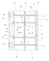
- FIG. 2 is a cross-sectional view of the tank outer wall showing the heat insulation structure.
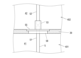
- FIG. 3 is a partially enlarged view of the heat insulating structure.
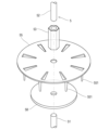
- FIG. 4 is a perspective view of the first washer and the sealing material.
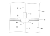
- FIG. 5 is a diagram showing a modified example of the arrangement of the sealing material.
- FIG. 6 is a diagram illustrating a method for applying the first thermal barrier layer.
- FIG. 1 is a vertical cross-sectional view showing a schematic configuration of a multi-shell tank 1 according to one embodiment of the present disclosure.
- the multi-shell tank 1 shown in FIG. 1 is a cryogenic container for storing low-temperature liquefied gas such as liquid hydrogen or liquefied natural gas.
- the multi-shell tank 1 may be a storage tank, a loading tank, or a fuel tank.
- the multi-shell tank 1 is supported on a foundation structure 10 via a support member such as a support skirt.
- the foundation structure 10 is not particularly limited, but examples include a ship's hull and a concrete base installed on the ground.
- the multi-shell tank 1 is a spherical tank.
- the multi-shell tank 1 is not limited to a spherical tank, and may be a deformed spherical tank having a prolate ellipsoid shape, a stretch tank having a cylindrical portion between the upper and lower parts, or a rectangular tank having a rectangular parallelepiped shape.
- the multi-shell tank 1 includes an inner tank 2 that contains liquefied gas, and an outer tank 3 that surrounds the inner tank 2.
- the inner tank 2 and the outer tank 3 are radially separated, and a low-temperature gas is filled in the space 13 between the inner tank 2 and the outer tank 3. This low-temperature gas is, for example, a vaporized gas of the liquefied gas contained in the inner tank 2.
- the outer surface of the inner tank 2 (hereinafter referred to as the "tank outer wall 20") is covered with a heat insulation structure 14.
- the heat insulation structure 14 suppresses heat input to the inner tank 2.
- the inner tank 2 becomes as cold as the liquefied gas, so the heat insulation structure 14 surrounding the inner tank 2 is required to have high heat insulation performance (i.e., cold retention performance). Therefore, in the heat insulation structure 14 provided in the multi-shelled tank 1 of this embodiment, multiple heat insulation layers are arranged in the thickness direction (i.e., the radial direction of the multi-shelled tank 1) to improve the heat insulation performance of the heat insulation structure 14.
- Fig. 2 is a cross-sectional view of the tank outer wall 20 showing the thermal insulation structure 14.
- the thermal insulation structure 14 includes at least two layers of thermal insulation panels, a first thermal insulation layer 401 consisting of a number of first thermal insulation panels 41 arranged in a plane on the outer side of the tank outer wall 20, and a second thermal insulation layer 402 consisting of a number of second thermal insulation panels 42 arranged in a plane on the outer side of the first thermal insulation layer 401.
- the outer side of the second thermal insulation layer 402 is covered with a surface layer 43 made of urethane foam.
- the side opposite the center of the inner tank 2 as viewed from the object is referred to as the "outside" of the object.
- the first insulation panel 41 and the second insulation panel 42 are not particularly limited and may be any insulation material formed into a panel shape.
- known panel-shaped insulation materials such as a panel made of urethane foam insulation material, a panel made of phenolic resin insulation material, a panel made of phenolic foam insulation material, or a panel made of a box filled with granular insulation material may be used as the first insulation panel 41 and the second insulation panel 42.
- the first insulation panel 41 and the second insulation panel 42 may be made of the same type of panel-shaped insulation material or different types of panel-shaped insulation materials.
- first heat insulation layer 401 the joints between the first insulation panels 41 are filled with joint material 37.
- second heat insulation layer 402 the joints between the second insulation panels 42 are filled with joint material 38.
- the joints between the first heat insulation layer 401 and the second heat insulation layer 402 are filled with joint material 39.
- joint materials 37, 38, and 39 joint materials that are resistant to low temperatures and elastic are preferable.
- An example of such a joint material is a foam joint material made of synthetic rubber.
- multiple types of joint materials may be used for each of the joint materials 37, 38, and 39.
- a spacer 47 is disposed between the tank outer wall 20 and the first heat insulation layer 401.
- the spacer 47 is made of an elastic material such as rigid polyurethane foam.
- the spacer 47 separates the tank outer wall 20 and the first heat insulation layer 401. This ensures a space between the tank outer wall 20 and the first heat insulation layer 401 in which low-temperature gas is present.
- the first insulation panel 41 and the second insulation panel 42 are fixed to the tank outer wall 20 by anchor bolts 5 fixed to the tank outer wall 20.
- the anchor bolts 5 have a base fixed to the tank outer wall 20 and penetrate the first heat insulation layer 401 and the second heat insulation layer 402.
- a nut 50 is screwed into the tip of the anchor bolt 5 protruding outward from the second heat insulation layer 402.
- the anchor bolts 5 are passed through the joints between the first insulation panels 41. However, the anchor bolts 5 may be passed through a through hole provided in the first insulation panel 41.
- the anchor bolts 5 are also passed through the joints between the second insulation panels 42. However, the anchor bolts 5 may be passed through a through hole provided in the second insulation panel 42.
- the anchor bolt 5 consists of two stud bolts 51, 52, a first stud bolt 51 and a second stud bolt 52, and an extension nut 53 that connects these stud bolts 51, 52 in series.
- the length of the first stud bolt 51 is greater than the thickness of the first heat insulating layer 401.
- a first washer 55 is placed between the first heat insulation layer 401 and the second heat insulation layer 402 and is passed through the anchor bolt 5.
- a sealant 58 is placed between the first heat insulation layer 401 and the first washer 55.
- the sealant 58 and the first washer 55 passed through the anchor bolt 5 are pressed against the first heat insulation layer 401 by an extension nut 53 screwed into the anchor bolt 5, restricting outward movement relative to the anchor bolt 5.
- the laminate consisting of the spacer 47, the first heat insulation layer 401, and the sealant 58 is held between the tank outer wall 20 and the first washer 55.
- FIG. 3 is a partially enlarged view of the heat insulation structure 14, and FIG. 4 is a perspective view of the first washer 55 and the sealing material 58.
- the first washer 55 according to this embodiment is disk-shaped.
- the first washer 55 is not limited to a disk shape, and may be a polygonal plate shape.
- a through hole for passing the anchor bolt 5 is provided at approximately the center of the first washer 55.
- a plurality of pins 551 protruding toward the first heat insulation layer 401 are provided on the surface of the first washer 55 facing the first heat insulation layer 401. The pins 551 are inserted into the first heat insulation layer 401 to suppress relative movement between the first heat insulation layer 401 and the first washer 55.
- the sealing material 58 is disposed between the first heat insulating layer 401 and the first washer 55 so as to contact the surface of the first washer 55 facing the first heat insulating layer 401.
- a recess 45 may be provided in the first heat insulating layer 401, and a part of the sealing material 58 may be fitted into the recess 45.
- the sealing material 58 according to this embodiment is disc-shaped with a diameter slightly smaller than that of the first washer 55.
- the sealing material 58 is not limited to a disc shape, and may be a polygonal plate shape.
- a through hole for passing the anchor bolt 5 is provided at approximately the center of the sealing material 58.
- the sealing material 58 is made of a material having low temperature resistance and elasticity, although it is not particularly limited thereto. An example of such a material is a foam made of synthetic rubber.
- the sealing material 58 is not limited to the above embodiment as long as it can suppress gas convection through the gap between the first thermal insulation layer 401 and the anchor bolt 5.
- the sealing material 58 may be a caulking material filled in the gap between the anchor bolt 5 and the first thermal insulation layer 401 in the surface portion of the first thermal insulation layer 401 facing the first washer 55.
- a second washer 56 is placed between the second heat insulation layer 402 and the nut 50 and is passed through the anchor bolt 5.
- the second washer 56 is pressed against the second heat insulation layer 402 by the nut 50 screwed onto the anchor bolt 5, restricting outward movement relative to the anchor bolt 5. This holds the second heat insulation layer 402 between the first washer 55 and the second washer 56.
- the first washer 55 is made of metal to reduce thickness and provide low temperature resistance and rigidity.
- the thickness of the first washer 55 is preferably 1/2 or less of the interlayer distance between the first heat insulating layer 401 and the second heat insulating layer 402.
- the environment in which the second washer 56 is placed is less cold than the environment in which the first washer 55 is placed. Therefore, the second washer 56 is made of resin, which is less expensive than metal. The rigidity of the second washer 56 is ensured by its thickness.
- ⁇ Construction method of heat insulation structure 14> a method of constructing the thermal insulation structure 14 will be described. First, only the first stud bolts 51 of the anchor bolts 5 are fixed to the tank outer wall 20. Next, a spacer 47 is arranged on the outside of the tank outer wall 20, and a first insulation panel 41 is arranged on the outside of the spacer 47. As shown in Fig. 6, a plurality of first insulation panels 41 are arranged in a plane shape so as to cover the tank outer wall 20. The first stud bolts 51 are passed through the joints between the first insulation panels 41 arranged in this manner. The joints between the first insulation panels 41 are filled with a joint material 37 to form a first thermal insulation layer 401.
- the sealant 58 and the first washer 55 are passed through the first stud bolt 51, and the extension nut 53 is screwed onto the first stud bolt 51.
- the extension nut 53 is tightened so that the first heat insulation layer 401 is sandwiched between the spacer 47 and the first washer 55. This fixes the first heat insulation layer 401 to the tank outer wall 20.
- the second stud bolt 52 is screwed into the extension nut 53, thereby extending the anchor bolt 5.
- the first insulation panel 41 is installed, only the first stud bolt 51 protrudes from the tank outer wall 20, so the installation work of the first insulation panel 41 is not hindered by the anchor bolt 5.
- the second insulation panel 42 is placed on the outside of the first heat insulation layer 401 via a joint material 39.
- the second insulation panels 42 are arranged in a planar manner so as to cover the outside of the first insulation panel 41.
- a second stud bolt 52 is passed through the joints between the second insulation panels 42 arranged in this manner.
- the joints between the second insulation panels 42 are filled with joint material 38 to form the second heat insulation layer 402.
- a second washer 56 is passed through the second stud bolt 52, and a nut 50 is screwed onto the second stud bolt 52.
- the nut 50 is tightened so that the second heat insulation layer 402 is sandwiched between the first washer 55 and the second washer 56. This fixes the second heat insulation layer 402 to the tank outer wall 20.
- on-site applied urethane is sprayed onto the outside of the second heat insulation layer 402, and the surface layer 43 is formed of hard polyurethane foam.
- the entire surface layer 43 may be formed of on-site applied urethane, or only a portion of the surface layer 43 may be formed of on-site applied urethane.
- a heat insulation structure 14 surrounding the inner tank 2 is provided.
- the heat insulation structure 14 of this embodiment surrounds the inner tank 2 between the inner and outer tanks 13, but the arrangement of the heat insulation structure 14 is not limited to this.
- a heat insulation structure arranged on the outside of the outer tank 3 and surrounding the outer tank 3 may be configured in the same manner as the heat insulation structure 14 of this embodiment.
- the thermal insulation structure 14 of the tank according to the first aspect of the present disclosure is A first heat insulating layer 401 having a plurality of first heat insulating panels 41 arranged in a planar manner on the outer side of the tank outer wall 20; a second thermal barrier layer 402 having a plurality of second heat insulating panels 42 arranged in a planar shape on the outer side of the first thermal barrier layer 401; an anchor bolt 5 having a base fixed to the tank outer wall 20 and penetrating the first thermal insulation layer 401 and the second thermal insulation layer 402; A first nut 50 is screwed onto a tip portion of the anchor bolt 5 protruding outward from the second thermal insulation layer 402; a first washer 55 disposed between the first thermal insulation layer 401 and the second thermal insulation layer 402 and passed through the anchor bolt 5; a second nut 53 that is screwed onto the anchor bolt 5 and restricts movement of the first washer 55; and a second washer 56 that is disposed between the second thermal insulation layer 40
- the tank thermal insulation structure 14 configured as above has a thermal insulation layer consisting of two layers of insulating panels, the first thermal insulation layer 401 and the second thermal insulation layer 402. Therefore, the tank thermal insulation structure 14 can have higher thermal insulation performance than a structure having a single insulating panel layer.
- the first thermal insulation layer 401 can be fixed to the tank outer wall 20 independently of the second thermal insulation layer 402
- the second thermal insulation layer 402 can be fixed to the tank outer wall 20 independently of the first thermal insulation layer 401.
- each of the thermal insulation layers 401 and 402 is well held to the tank outer wall 20.
- the tank thermal insulation structure 14 according to the second item of the present disclosure is the tank thermal insulation structure 14 according to the first item, further comprising a sealant 58 disposed between the first thermal insulation layer 401 and the first washer 55 to seal the gap between the first thermal insulation layer 401 and the anchor bolt 5.
- a small gap may occur between the first heat insulating layer 401 and the anchor bolt 5, but by sealing at least a portion of this gap with the sealing material 58, gas convection through this gap can be suppressed.
- the thermal insulation structure 14 of the tank according to the third item of the present disclosure is the thermal insulation structure 14 of the tank according to the first or second item, in which the first washer 55 is made of metal and has a thickness that is less than half the interlayer distance between the first thermal insulation layer 401 and the second thermal insulation layer 402.
- the first washer 55 By using the first washer 55 made of metal, the first washer 55 has low temperature resistance and rigidity while keeping the thickness low. By using the first washer 55 with a reduced thickness in this way, the interlayer distance between the first heat insulating layer 401 and the second heat insulating layer 402 is reduced.
- the tank heat insulation structure 14 according to the fourth item of the present disclosure is the tank heat insulation structure 14 according to the first or second item, in which the first washer 55 is made of metal, and the second washer 56 is thicker than the first washer 55 and made of resin.
- the tank heat insulation structure 14 according to the fifth item of the present disclosure is a tank heat insulation structure 14 according to any one of the first to fourth items, in which the anchor bolt 5 has at least two stud bolts 51, 52, and the stud bolts 51, 52 are connected in series with each other by a second nut (extension nut 53 in the above embodiment).
- the tank thermal insulation structure 14 according to the sixth item of the present disclosure is the tank thermal insulation structure 14 according to any one of the first to fifth items, further comprising a surface layer 43 made of expanded urethane foam and arranged on the outside of the second thermal insulation layer 402.
- the surface layer 43 seals the gap between the second heat insulation layer 402 and the anchor bolt 5, and the gap between the second heat insulation layer 402 and the second washer 56, suppressing gas convection through these gaps.
- the tank thermal insulation structure 14 according to the seventh item of the present disclosure is a tank thermal insulation structure 14 according to any one of the first to sixth items, in which the gap between the first thermal insulation layer 401 and the second thermal insulation layer 402 is filled with an elastic joint material 39.
- the multi-shell tank 1 according to the eighth item of the present disclosure comprises an inner tank 2, an outer tank 3 surrounding the inner tank 2, and a thermal insulation structure 14 for a tank according to any one of the first to seventh items, which is disposed between the inner tank 2 and the outer tank 3 and fixed to the outer wall of the inner tank 2.
- the heat insulation structure 14 of the tank described above is suitable as a heat insulation structure to be placed between the inner and outer tanks 13, which is at a lower temperature than the outside of the outer tank 3.
Landscapes
- Engineering & Computer Science (AREA)
- Physics & Mathematics (AREA)
- Thermal Sciences (AREA)
- Mechanical Engineering (AREA)
- General Engineering & Computer Science (AREA)
- Filling Or Discharging Of Gas Storage Vessels (AREA)
Abstract
タンクの防熱構造は、タンク外壁の外側に面状に並べられた複数の第1断熱パネルを有する第1防熱層と、第1防熱層の外側に面状に並べられた複数の第2断熱パネルを有する第2防熱層と、タンク外壁に固定された基部を有し、第1防熱層及び第2防熱層を貫通するアンカーボルトと、アンカーボルトの第2防熱層から外側へ突出した先端部に螺入された第1ナットと、第1防熱層と第2防熱層の間に配置されて、アンカーボルトに通された第1ワッシャと、アンカーボルトに螺入されて、第1ワッシャの移動を規制する第2ナットと、第2防熱層と第1ナットの間に配置されて、アンカーボルトに通された第2ワッシャと、を備える。
Description
本開示は、液化ガスを収容するタンクの防熱構造に関する。
従来、液化天然ガスや液化窒素などの低温の液化ガスを収容するタンクは、外部からの入熱を遮断してタンク内を保冷するための防熱構造を備える。このような防熱構造として、タンク外壁を被覆する防熱層がある。防熱層の施工方法としては、パネル工法が知られている。例えば、特許文献1では、パネル工法で施工されたタンクの防熱構造が開示されている。
特許文献1のタンクの防熱構造は、ポリウレタンフォームで成形された断熱材ブロックが、タンク外表面に支持杆で拘止されたものである。支持杆は、タンク外壁に溶着されたスタッドと、スタッドのネジ穴に螺合するボルトと、ボルトに挿着される座金とからなる。座金を挿着したボルトは断熱材ブロックが有する貫入孔に貫入されており、スタッドと座金の間に断熱材ブロックが挟み込まれている。
液化水素を収容するタンクとして、内槽と外槽の二重殻を備えた多重殻タンクが知られている。発明者らは、多重殻タンクに極低温の液化水素を収容するために十分な防熱性能を備えるために、内槽を被覆する防熱層を内外槽間に配置するとともに、内外槽間に水素ガスなどの外気よりも低温の気体を充填することを検討している。このような多重殻タンクにおいて、液化水素を収容する内槽を被覆する防熱層は、液化天然ガスや液体窒素を収容するタンクと比較して、より低温環境に晒され、また、高い防熱性能(即ち、保冷性能)が要求される。
本開示は以上の事情に鑑みてされたものであり、その目的は、従来と比較してより高い防熱性能を備えるタンクの防熱構造を提供することにある。
上記課題を解決するために、本開示の一態様に係るタンクの防熱構造は、
タンク外壁の外側に面状に並べられた複数の第1断熱パネルを有する第1防熱層と、
前記第1防熱層の外側に面状に並べられた複数の第2断熱パネルを有する第2防熱層と、
前記タンク外壁に固定された基部を有し、前記第1防熱層及び前記第2防熱層を貫通するアンカーボルトと、
前記アンカーボルトの前記第2防熱層から外側へ突出した先端部に螺入された第1ナットと、
前記第1防熱層と前記第2防熱層の間に配置されて、前記アンカーボルトに通された第1ワッシャと、
前記アンカーボルトに螺入されて、前記第1ワッシャの移動を規制する第2ナットと、
前記第2防熱層と前記第1ナットの間に配置されて、前記アンカーボルトに通された第2ワッシャと、を備えるものである。
また、本開示の一態様に係る多重殻タンクは、内槽と、前記内槽を囲む外槽と、前記内槽と前記外槽の槽間に配置されて前記内槽の外壁に固定された、前記タンクの防熱構造とを、備えるものである。
本開示によれば、従来と比較してより高い防熱性能を備えるタンクの防熱構造を提供できる。
次に、図面を参照して本開示の実施の形態を説明する。図1は本開示の一実施形態に係る多重殻タンク1の概略構成を示す垂直断面図である。図1に示す多重殻タンク1は、液体水素や液化天然ガス等の低温の液化ガスを貯蔵する低温容器である。多重殻タンク1は、貯蔵用タンク、荷役用タンク、又は燃料用タンクであってよい。多重殻タンク1は、支持スカートなどの支持部材を介して基礎構造物10に支持される。基礎構造物10は、特に限定されないが、船体や地上に設置されたコンクリート製基台が例示される。
<多重殻タンク1の概略構成>
多重殻タンク1は球形タンクである。但し、多重殻タンク1は、球形タンクに限定されず、扁長楕円体状の変形球形タンクや、上部と下部の間に筒部を有するストレッチタンクや、直方体状の方形タンクであってもよい。多重殻タンク1は、液化ガスを収容する内槽2と、内槽2を包囲する外槽3とを備える。内槽2と外槽3とは径方向に隔てられており、内槽2と外槽3の間の内外槽間13には低温ガスが充填されている。この低温ガスは、例えば、内槽2に収容された液化ガスの気化ガスである。
多重殻タンク1は球形タンクである。但し、多重殻タンク1は、球形タンクに限定されず、扁長楕円体状の変形球形タンクや、上部と下部の間に筒部を有するストレッチタンクや、直方体状の方形タンクであってもよい。多重殻タンク1は、液化ガスを収容する内槽2と、内槽2を包囲する外槽3とを備える。内槽2と外槽3とは径方向に隔てられており、内槽2と外槽3の間の内外槽間13には低温ガスが充填されている。この低温ガスは、例えば、内槽2に収容された液化ガスの気化ガスである。
内外槽間13において、内槽2の外表面(以下、「タンク外壁20」と称する)は防熱構造14で覆われている。防熱構造14によって、内槽2への入熱が抑制されている。内槽2に低温の液化ガスが収容されると内槽2は液化ガスと同程度の低温となることから、内槽2を包囲する防熱構造14には高い防熱性能(即ち、保冷性能)が要求される。そこで、本実施形態に係る多重殻タンク1が具備する防熱構造14では、厚さ方向(即ち、多重殻タンク1の径方向)に複数の防熱層を配置して、防熱構造14の防熱性能を向上させている。
<防熱構造14>
図2は、防熱構造14を示すタンク外壁20の断面図である。図2に示すように、防熱構造14は、タンク外壁20の外側に面状に並べられた多数の第1断熱パネル41からなる第1防熱層401と、第1防熱層401の外側に面状に並べられた多数の第2断熱パネル42からなる第2防熱層402との、少なくとも二層の断熱パネルの層を備える。第2防熱層402の外側は発泡ウレタンからなる表層43によって被覆されている。なお、本明細書において対象物から見て内槽2の中心と反対側を対象物の「外側」と称する。
図2は、防熱構造14を示すタンク外壁20の断面図である。図2に示すように、防熱構造14は、タンク外壁20の外側に面状に並べられた多数の第1断熱パネル41からなる第1防熱層401と、第1防熱層401の外側に面状に並べられた多数の第2断熱パネル42からなる第2防熱層402との、少なくとも二層の断熱パネルの層を備える。第2防熱層402の外側は発泡ウレタンからなる表層43によって被覆されている。なお、本明細書において対象物から見て内槽2の中心と反対側を対象物の「外側」と称する。
第1断熱パネル41及び第2断熱パネル42は、特に限定されず、パネル状に成形された断熱材であればよい。例えば、ウレタンフォーム断熱材からなるパネル、フェノールレジン断熱材からなるパネル、フェノールフォーム断熱材からなるパネル、ボックスに粒状断熱材が充填されてなるパネル、などの公知のパネル状断熱材が第1断熱パネル41及び第2断熱パネル42として採用されうる。第1断熱パネル41及び第2断熱パネル42は、同種のパネル状断熱材であってもよいし、異種のパネル状断熱材であってもよい。
第1防熱層401において、第1断熱パネル41同士の目地には目地材37が充填されている。第2防熱層402において、第2断熱パネル42同士の目地には目地材38が充填されている。また、第1防熱層401と第2防熱層402の目地には目地材39が充填されている。目地材37,38,39は、特に限定されないが、耐低温性と弾性を有する目地材が好ましい。このような目地材として、合成ゴムからなる発泡目地材が例示される。また、各目地材37,38,39において、複数種類の目地材が使い分けられていてもよい。
タンク外壁20と第1防熱層401の間には、スペーサ47が配置されている。スペーサ47は、例えば、硬質ポリウレタンフォームなどの弾性を有する材料で構成されている。スペーサ47は、タンク外壁20と第1防熱層401とを離間させる。これにより、タンク外壁20と第1防熱層401の間に低温ガスが存在する空間が確保される。
第1断熱パネル41及び第2断熱パネル42は、タンク外壁20に固定されたアンカーボルト5等によってタンク外壁20に固定されている。アンカーボルト5は、タンク外壁20に固定された基部を有し、第1防熱層401及び第2防熱層402を貫通している。アンカーボルト5の第2防熱層402から外側へ突出した先端部にはナット50が螺入されている。アンカーボルト5は、第1断熱パネル41同士の目地を通されている。但し、アンカーボルト5は、第1断熱パネル41に設けられた貫通孔に通されていてもよい。また、アンカーボルト5は、第2断熱パネル42同士の目地を通されている。但し、アンカーボルト5は、第2断熱パネル42に設けられた貫通孔に通されていてもよい。
アンカーボルト5は、第1スタッドボルト51及び第2スタッドボルト52の2本のスタッドボルト51,52と、これらのスタッドボルト51,52を直列に接続するエクステンションナット53からなる。第1スタッドボルト51の長さは第1防熱層401の層厚よりも大きい。
アンカーボルト5には、第1防熱層401と第2防熱層402の間に配置された第1ワッシャ55が通されている。第1防熱層401と第1ワッシャ55との間には封止材58が配置されている。アンカーボルト5に通された封止材58と第1ワッシャ55は、アンカーボルト5に螺入されたエクステンションナット53によって第1防熱層401へ押し付けられて、アンカーボルト5に相対する外側への移動が規制されている。これにより、スペーサ47、第1防熱層401、及び封止材58からなる積層体は、タンク外壁20と第1ワッシャ55の間に保持されている。
図3は、防熱構造14の一部拡大図であり、図4は、第1ワッシャ55と封止材58の斜視図である。図3及び図4に示すように、本実施形態に係る第1ワッシャ55は円盤状を呈する。但し、第1ワッシャ55は、円盤状に限定されず、多角形板状であってもよい。第1ワッシャ55の略中央にはアンカーボルト5を通すための貫通孔が設けられている。第1ワッシャ55の第1防熱層401へ向いた面には第1防熱層401へ向けて突出する複数のピン551が設けられている。このピン551は、第1防熱層401に刺さって、第1防熱層401と第1ワッシャ55の相対移動を抑制する。
封止材58は、第1ワッシャ55の第1防熱層401へ向いた面と接触するように、第1防熱層401と第1ワッシャ55の間に配置されている。但し、図5に示すように、第1防熱層401に凹部45が設けられ、当該凹部45に封止材58の一部が嵌め込まれていてもよい。本実施形態に係る封止材58は、第1ワッシャ55よりも若干小さな径の円盤状を呈する。但し、封止材58は、円盤状に限定されず、多角形板状であってもよい。封止材58の略中央には、アンカーボルト5を通すための貫通孔が設けられている。封止材58は、特に限定されないが、耐低温性と弾性を有する材料で構成されている。このような材料として、合成ゴムからなる発泡体が例示される。
第1防熱層401に通されたアンカーボルト5の周囲にはわずかな空隙が生じるが、この空隙の一部が封止材58によって封止されている。これにより空隙を通じた気体の対流が抑制される。封止材58は、第1防熱層401とアンカーボルト5の空隙を通じた気体の対流が抑制できれば、上記の態様に限定されない。例えば、封止材58は、第1防熱層401の第1ワッシャ55と対峙する表層部分において、アンカーボルト5と第1防熱層401の空隙に充填されたコーキング材であってもよい。
アンカーボルト5には、第2防熱層402とナット50との間に配置された第2ワッシャ56が通されている。アンカーボルト5に第2ワッシャ56は、アンカーボルト5に螺入されたナット50によって第2防熱層402へ押し付けられて、アンカーボルト5に相対する外側への移動が規制されている。これにより、第2防熱層402は、第1ワッシャ55と第2ワッシャ56の間に保持されている。
第1ワッシャ55は、厚さを抑え、耐低温性且つ剛性を備えるために、金属製である。第1ワッシャ55の厚さは第1防熱層401と第2防熱層402の層間距離の1/2以下が好ましい。第2ワッシャ56の置かれる環境は、第1ワッシャ55が置かれる環境と比較して低温が緩和されている。そこで、第2ワッシャ56は、金属製と比較して安価な樹脂製である。第2ワッシャ56の剛性は厚さによって確保されている。
<防熱構造14の施工方法>
ここで、防熱構造14の施工方法を説明する。まず、タンク外壁20にアンカーボルト5のうち第1スタッドボルト51のみが固定される。続いて、タンク外壁20の外側にスペーサ47が配置され、スペーサ47の外側に第1断熱パネル41が配置される。図6に示すように、複数の第1断熱パネル41は、タンク外壁20を覆うように面状に並べられる。このように並んだ第1断熱パネル41同士の目地に第1スタッドボルト51が通されている。第1断熱パネル41同士の目地が目地材37で埋められて、第1防熱層401が形成される。
ここで、防熱構造14の施工方法を説明する。まず、タンク外壁20にアンカーボルト5のうち第1スタッドボルト51のみが固定される。続いて、タンク外壁20の外側にスペーサ47が配置され、スペーサ47の外側に第1断熱パネル41が配置される。図6に示すように、複数の第1断熱パネル41は、タンク外壁20を覆うように面状に並べられる。このように並んだ第1断熱パネル41同士の目地に第1スタッドボルト51が通されている。第1断熱パネル41同士の目地が目地材37で埋められて、第1防熱層401が形成される。
次に、第1スタッドボルト51に封止材58及び第1ワッシャ55が順に通され、第1スタッドボルト51にエクステンションナット53が螺入される。スペーサ47及び第1ワッシャ55によって第1防熱層401が挟み込まれるように、エクステンションナット53が締められる。これにより、第1防熱層401がタンク外壁20に固定される。
続いて、エクステンションナット53に第2スタッドボルト52が螺入されることによって、アンカーボルト5が延長される。第1断熱パネル41の敷設時には第1スタッドボルト51のみがタンク外壁20から突き出した状態となっているので、アンカーボルト5によって第1断熱パネル41の敷設作業が阻害されない。また、封止材58及び第1ワッシャ55のアンカーボルト5への挿入や、エクステンションナット53のアンカーボルト5への螺入が容易となる。
第1防熱層401の外側に目地材39を介して第2断熱パネル42が配置される。複数の第2断熱パネル42は、第1断熱パネル41の外側を覆うように面状に並べられる。このように並んだ第2断熱パネル42同士の目地に第2スタッドボルト52が通されている。第2断熱パネル42同士の目地が目地材38で埋められて、第2防熱層402が形成される。続いて、第2スタッドボルト52に第2ワッシャ56が通され、第2スタッドボルト52にナット50が螺入される。第1ワッシャ55及び第2ワッシャ56によって第2防熱層402が挟み込まれるように、ナット50が締められる。これにより、第2防熱層402がタンク外壁20に固定される。
最後に、第2防熱層402の外側に現場施工ウレタンが吹き付けられ、硬質ポリウレタンフォームによって表層43が形成される。なお、表層43の全てが現場施工ウレタンによって形成されていてもよいし、表層43の一部が現場施工ウレタンによって形成されていてもよい。以上により、内槽2を囲む防熱構造14が備えられる。なお、本実施形態に係る防熱構造14は、内槽2と外槽3の内外槽間13において内槽2を包囲するものであるが、防熱構造14の配置はこれに限定されるものではない。例えば外槽3の外側に配置され当該外槽3を包囲する防熱構造が、本実施形態に係る防熱構造14と同様に構成され得る。
〔総括〕
以上に説明した通り、本開示の第1の項目に係るタンクの防熱構造14は、
タンク外壁20の外側に面状に並べられた複数の第1断熱パネル41を有する第1防熱層401と、
第1防熱層401の外側に面状に並べられた複数の第2断熱パネル42を有する第2防熱層402と、
タンク外壁20に固定された基部を有し、第1防熱層401及び第2防熱層402を貫通するアンカーボルト5と、
アンカーボルト5の第2防熱層402から外側へ突出した先端部に螺入された第1ナット50と、
第1防熱層401と第2防熱層402の間に配置されて、アンカーボルト5に通された第1ワッシャ55と、
アンカーボルト5に螺入されて、第1ワッシャ55の移動を規制する第2ナット53と、
第2防熱層402と第1ナット50の間に配置されて、アンカーボルト5に通された第2ワッシャ56と、を備えるものである。
上記構成のタンクの防熱構造14は、第1防熱層401と第2防熱層402の二層の断熱パネルからなる防熱層を有する。よって、タンクの防熱構造14は、一層の断熱パネル層を有する場合と比較して、高い防熱性能を備え得る。また、第1防熱層401と第2防熱層402の間に第1ワッシャ55が配置されることで、第1防熱層401を第2防熱層402から独立してタンク外壁20に固定でき、第2防熱層402を第1防熱層401から独立してタンク外壁20に固定できる。このように防熱層401,402が互いに独立してタンク外壁20に固定されることで、防熱層401,402に熱膨張・熱収縮による変形量に差異が生じた場合でも、各防熱層401,402がタンク外壁20に良好に保持される。
本開示の第2の項目に係るタンクの防熱構造14は、第1の項目に係るタンクの防熱構造14において、第1防熱層401と第1ワッシャ55の間に配置されて、第1防熱層401とアンカーボルト5の間の空隙を封止する封止材58を、更に備えるものである。
第1防熱層401とアンカーボルト5の間には僅かな空隙が生じうるが、この空隙の少なくとも一部分が封止材58によって封止されることによって、この空隙を通じた気体の対流を抑制できる。
本開示の第3の項目に係るタンクの防熱構造14は、第1又は2の項目に係るタンクの防熱構造14において、第1ワッシャ55は金属製であり、第1防熱層401と第2防熱層402の層間距離の半分以下の厚さを有するものである。
金属製の第1ワッシャ55が採用されることによって、第1ワッシャ55は厚さを抑えながら、耐低温性と剛性を備える。このように厚さを抑えた第1ワッシャ55が採用されることによって、第1防熱層401と第2防熱層402の層間距離が抑えられる。
本開示の第4の項目に係るタンクの防熱構造14は、第1又は2の項目に係るタンクの防熱構造14において、第1ワッシャ55は金属製であり、第2ワッシャ56は第1ワッシャ55よりも厚みが大きく且つ樹脂製であるものである。
樹脂製の第2ワッシャ56が採用されることによって、第1ワッシャ55及び第2ワッシャ56の両方に金属製ワッシャが採用される場合と比較してコストが抑えられる。
本開示の第5の項目に係るタンクの防熱構造14は、第1乃至4のいずれかの項目に係るタンクの防熱構造14において、アンカーボルト5は、少なくとも2本のスタッドボルト51,52を有し、第2ナット(上記実施形態では、エクステンションナット53)によってスタッドボルト51,52同士が直列に接続されているものである。
タンク外壁20に第1断熱パネル41の敷設作業の際に、タンク外壁20に第1スタッドボルト51のみを固定しておくことによって、作業を阻害しうるアンカーボルト5の長さが抑えられるので、作業性が向上する。
本開示の第6の項目に係るタンクの防熱構造14は、第1乃至5のいずれかの項目に係るタンクの防熱構造14において、第2防熱層402の外側に配置された、発泡ウレタンフォームからなる表層43を、更に備えるものである。
表層43によって、第2防熱層402とアンカーボルト5の間の空隙、第2防熱層402と第2ワッシャ56の間の空隙が塞がれ、これらの空隙を通じた気体の対流を抑制できる。
本開示の第7の項目に係るタンクの防熱構造14は、第1乃至6のいずれかの項目に係るタンクの防熱構造14において、第1防熱層401と第2防熱層402の層間が弾性を有する目地材39で埋められているものである。
これにより、第1防熱層401と第2防熱層402の層間における気体の対流を抑制できる。
本開示の第8の項目に係る多重殻タンク1は、内槽2と、内槽2を囲む外槽3と、内槽2と外槽3の槽間に配置されて、内槽2の外壁に固定された第1乃至7のいずれかの項目に係るタンクの防熱構造14とを、備えるものである。
上記のタンクの防熱構造14は、外槽3の外側と比較して低温の内外槽間13に配置される防熱構造として好適である。
以上の本開示の議論は、例示及び説明の目的で提示されたものであり、本開示を本明細書に開示される形態に限定することを意図するものではない。例えば、前述の詳細な説明では、本開示の様々な特徴は、本開示を合理化する目的で1つの実施形態に纏められているが、複数の特徴のうち幾つかが組み合わされてもよい。また、本開示に含まれる複数の特徴は、上記で論じたもの以外の代替の実施形態、構成、又は態様に組み合わされてもよい。
Claims (8)
- タンク外壁の外側に面状に並べられた複数の第1断熱パネルを有する第1防熱層と、
前記第1防熱層の外側に面状に並べられた複数の第2断熱パネルを有する第2防熱層と、
前記タンク外壁に固定された基部を有し、前記第1防熱層及び前記第2防熱層を貫通するアンカーボルトと、
前記アンカーボルトの前記第2防熱層から外側へ突出した先端部に螺入された第1ナットと、
前記第1防熱層と前記第2防熱層の間に配置されて、前記アンカーボルトに通された第1ワッシャと、
前記アンカーボルトに螺入されて、前記第1ワッシャの移動を規制する第2ナットと、
前記第2防熱層と前記第1ナットの間に配置されて、前記アンカーボルトに通された第2ワッシャと、を備える、
タンクの防熱構造。 - 前記第1防熱層と前記第1ワッシャの間に配置されて、前記第1防熱層と前記アンカーボルトの間の空隙を封止する封止材を、更に備える、
請求項1に記載のタンクの防熱構造。 - 前記第1ワッシャは金属製であり、前記第1防熱層と前記第2防熱層の層間距離の半分以下の厚さを有する、
請求項1又は2に記載のタンクの防熱構造。 - 前記第1ワッシャは金属製であり、
前記第2ワッシャは前記第1ワッシャよりも厚みが大きく且つ樹脂製である、
請求項1又は2に記載のタンクの防熱構造。 - 前記アンカーボルトは、少なくとも2本のスタッドボルトを有し、前記第2ナットによって前記スタッドボルト同士が直列に接続されている、
請求項1乃至4のいずれか一項に記載のタンクの防熱構造。 - 前記第2防熱層の外側に配置された、発泡ウレタンフォームからなる表層を、更に備える、
請求項1乃至5のいずれか一項に記載のタンクの防熱構造。 - 前記第1防熱層と前記第2防熱層の層間が弾性を有する目地材で埋められている、
請求項1乃至6のいずれか一項に記載のタンクの防熱構造。 - 内槽と、
前記内槽を囲む外槽と、
前記内槽と前記外槽の槽間に配置されて前記内槽の外壁に固定された、請求項1乃至7のいずれか一項に記載のタンクの防熱構造とを、備える、
多重殻タンク。
Priority Applications (1)
| Application Number | Priority Date | Filing Date | Title |
|---|---|---|---|
| PCT/JP2022/035917 WO2024069747A1 (ja) | 2022-09-27 | 2022-09-27 | タンクの防熱構造及び多重殻タンク |
Applications Claiming Priority (1)
| Application Number | Priority Date | Filing Date | Title |
|---|---|---|---|
| PCT/JP2022/035917 WO2024069747A1 (ja) | 2022-09-27 | 2022-09-27 | タンクの防熱構造及び多重殻タンク |
Publications (1)
| Publication Number | Publication Date |
|---|---|
| WO2024069747A1 true WO2024069747A1 (ja) | 2024-04-04 |
Family
ID=90476829
Family Applications (1)
| Application Number | Title | Priority Date | Filing Date |
|---|---|---|---|
| PCT/JP2022/035917 Ceased WO2024069747A1 (ja) | 2022-09-27 | 2022-09-27 | タンクの防熱構造及び多重殻タンク |
Country Status (1)
| Country | Link |
|---|---|
| WO (1) | WO2024069747A1 (ja) |
Citations (6)
| Publication number | Priority date | Publication date | Assignee | Title |
|---|---|---|---|---|
| JPS55117622U (ja) * | 1979-02-14 | 1980-08-20 | ||
| JPS5985076A (ja) * | 1982-11-02 | 1984-05-16 | 株式会社 石井鉄工所 | 二重殻球形タンクの組立方法 |
| JPH04194497A (ja) * | 1990-11-28 | 1992-07-14 | Mitsubishi Heavy Ind Ltd | 厚物多層防熱材の取付構造 |
| JPH08233199A (ja) * | 1995-02-23 | 1996-09-10 | Kawasaki Heavy Ind Ltd | 極低温タンク用防熱構造および防熱パネル |
| JPH11278584A (ja) * | 1998-03-31 | 1999-10-12 | Ishii Iron Works Co Ltd | 二重殻貯槽の内槽支持構造 |
| JP2003294197A (ja) * | 2002-04-01 | 2003-10-15 | Kawasaki Shipbuilding Corp | 極低温タンク用防熱構造 |
-
2022
- 2022-09-27 WO PCT/JP2022/035917 patent/WO2024069747A1/ja not_active Ceased
Patent Citations (6)
| Publication number | Priority date | Publication date | Assignee | Title |
|---|---|---|---|---|
| JPS55117622U (ja) * | 1979-02-14 | 1980-08-20 | ||
| JPS5985076A (ja) * | 1982-11-02 | 1984-05-16 | 株式会社 石井鉄工所 | 二重殻球形タンクの組立方法 |
| JPH04194497A (ja) * | 1990-11-28 | 1992-07-14 | Mitsubishi Heavy Ind Ltd | 厚物多層防熱材の取付構造 |
| JPH08233199A (ja) * | 1995-02-23 | 1996-09-10 | Kawasaki Heavy Ind Ltd | 極低温タンク用防熱構造および防熱パネル |
| JPH11278584A (ja) * | 1998-03-31 | 1999-10-12 | Ishii Iron Works Co Ltd | 二重殻貯槽の内槽支持構造 |
| JP2003294197A (ja) * | 2002-04-01 | 2003-10-15 | Kawasaki Shipbuilding Corp | 極低温タンク用防熱構造 |
Similar Documents
| Publication | Publication Date | Title |
|---|---|---|
| US12571502B2 (en) | Wall for a leaktight and thermally insulating vessel | |
| US20140255628A1 (en) | Thermal Insulation System for Non-Vacuum Applications Including a Multilayer Composite | |
| US4117947A (en) | Internal insulation for liquefied gas tank | |
| JP2021017920A (ja) | 液化ガス貯蔵タンク及びその建造方法 | |
| JP6909635B2 (ja) | 低温液化ガス貯蔵タンク | |
| JP7601908B2 (ja) | 多重殻タンク及び船舶 | |
| CN110998170B (zh) | 低温流体储存罐 | |
| AU2023254428A1 (en) | Wall for a leaktight and thermally insulating vessel | |
| JP2016161116A (ja) | 液化ガスタンクの球状曲面被覆用断熱パネル | |
| KR100981416B1 (ko) | 앵커 구조체 및 이를 갖는 액화천연가스 저장탱크 | |
| KR102018668B1 (ko) | 단열 패널 체결부 및 이를 구비한 액화가스 화물창의 단열 구조 | |
| KR20110058206A (ko) | 액화가스 저장탱크의 단열패널 결합구조 | |
| KR20090112790A (ko) | 액화천연가스 운반선 화물창의 단열구조 | |
| KR102351144B1 (ko) | 앵커 구조체를 포함하는 액화가스 화물창 및 이의 시공방법 | |
| KR100998554B1 (ko) | 액화천연가스 운반선 화물창의 단열구조 | |
| KR20220021739A (ko) | 액화가스 저장탱크의 단열층 및 멤브레인 고정장치 | |
| KR20160024016A (ko) | 화물창 방벽구조 | |
| WO2025253456A1 (ja) | タンク壁の断熱構造および液化水素運搬船 | |
| KR20110012989A (ko) | 액화가스 저장탱크의 단열구조 | |
| KR101712008B1 (ko) | 액화가스 화물창 및 그 제작방법 | |
| KR102947462B1 (ko) | 이중 금속 방벽 구조의 멤브레인형 액화가스 단열시스템 | |
| KR20100022201A (ko) | 액화천연가스 운반선 화물창의 단열구조 | |
| JP5916422B2 (ja) | 液化ガスタンクの保冷構造、液化ガスタンク及び浮体構造物 | |
| JP4101196B2 (ja) | 断熱構造 | |
| JP2809356B2 (ja) | 超低温貨物格納用タンクの真空式断熱パネル |
Legal Events
| Date | Code | Title | Description |
|---|---|---|---|
| 121 | Ep: the epo has been informed by wipo that ep was designated in this application |
Ref document number: 22960811 Country of ref document: EP Kind code of ref document: A1 |
|
| NENP | Non-entry into the national phase |
Ref country code: DE |
|
| 122 | Ep: pct application non-entry in european phase |
Ref document number: 22960811 Country of ref document: EP Kind code of ref document: A1 |
|
| NENP | Non-entry into the national phase |
Ref country code: JP |