WO2024062778A1 - 電池およびその製造方法 - Google Patents
電池およびその製造方法 Download PDFInfo
- Publication number
- WO2024062778A1 WO2024062778A1 PCT/JP2023/028216 JP2023028216W WO2024062778A1 WO 2024062778 A1 WO2024062778 A1 WO 2024062778A1 JP 2023028216 W JP2023028216 W JP 2023028216W WO 2024062778 A1 WO2024062778 A1 WO 2024062778A1
- Authority
- WO
- WIPO (PCT)
- Prior art keywords
- counter electrode
- electrode
- conductive
- layer
- current collector
- Prior art date
- Legal status (The legal status is an assumption and is not a legal conclusion. Google has not performed a legal analysis and makes no representation as to the accuracy of the status listed.)
- Ceased
Links
Images









Classifications
-
- H—ELECTRICITY
- H01—ELECTRIC ELEMENTS
- H01M—PROCESSES OR MEANS, e.g. BATTERIES, FOR THE DIRECT CONVERSION OF CHEMICAL ENERGY INTO ELECTRICAL ENERGY
- H01M10/00—Secondary cells; Manufacture thereof
- H01M10/05—Accumulators with non-aqueous electrolyte
- H01M10/052—Li-accumulators
-
- H—ELECTRICITY
- H01—ELECTRIC ELEMENTS
- H01M—PROCESSES OR MEANS, e.g. BATTERIES, FOR THE DIRECT CONVERSION OF CHEMICAL ENERGY INTO ELECTRICAL ENERGY
- H01M10/00—Secondary cells; Manufacture thereof
- H01M10/05—Accumulators with non-aqueous electrolyte
- H01M10/056—Accumulators with non-aqueous electrolyte characterised by the materials used as electrolytes, e.g. mixed inorganic/organic electrolytes
- H01M10/0561—Accumulators with non-aqueous electrolyte characterised by the materials used as electrolytes, e.g. mixed inorganic/organic electrolytes the electrolyte being constituted of inorganic materials only
- H01M10/0562—Solid materials
-
- H—ELECTRICITY
- H01—ELECTRIC ELEMENTS
- H01M—PROCESSES OR MEANS, e.g. BATTERIES, FOR THE DIRECT CONVERSION OF CHEMICAL ENERGY INTO ELECTRICAL ENERGY
- H01M10/00—Secondary cells; Manufacture thereof
- H01M10/05—Accumulators with non-aqueous electrolyte
- H01M10/058—Construction or manufacture
- H01M10/0585—Construction or manufacture of accumulators having only flat construction elements, i.e. flat positive electrodes, flat negative electrodes and flat separators
-
- H—ELECTRICITY
- H01—ELECTRIC ELEMENTS
- H01M—PROCESSES OR MEANS, e.g. BATTERIES, FOR THE DIRECT CONVERSION OF CHEMICAL ENERGY INTO ELECTRICAL ENERGY
- H01M50/00—Constructional details or processes of manufacture of the non-active parts of electrochemical cells other than fuel cells, e.g. hybrid cells
- H01M50/10—Primary casings; Jackets or wrappings
- H01M50/102—Primary casings; Jackets or wrappings characterised by their shape or physical structure
-
- H—ELECTRICITY
- H01—ELECTRIC ELEMENTS
- H01M—PROCESSES OR MEANS, e.g. BATTERIES, FOR THE DIRECT CONVERSION OF CHEMICAL ENERGY INTO ELECTRICAL ENERGY
- H01M50/00—Constructional details or processes of manufacture of the non-active parts of electrochemical cells other than fuel cells, e.g. hybrid cells
- H01M50/50—Current conducting connections for cells or batteries
- H01M50/531—Electrode connections inside a battery casing
- H01M50/54—Connection of several leads or tabs of plate-like electrode stacks, e.g. electrode pole straps or bridges
Definitions
- the present disclosure relates to a battery and a method for manufacturing the same.
- Patent Document 1 discloses a battery in which a plurality of unit cells connected in series and stacked are connected in parallel on the side surfaces of the unit cells.
- Patent Document 2 discloses a battery in which a current collector is made to protrude in order to connect a plurality of unit cells stacked in series in parallel on the side surfaces of the unit cells.
- the present disclosure provides a high-performance battery and a method for manufacturing the same.
- a battery according to one embodiment of the present disclosure includes a plurality of battery cells each having an electrode layer, a counter electrode layer, and a solid electrolyte layer located between the electrode layer and the counter electrode layer, and a plurality of current collectors. and a power generation element in which the plurality of battery cells and the plurality of current collectors are stacked so that at least some of the plurality of battery cells are electrically connected in parallel, and a power generation element provided on a side surface of the power generation element.
- Each of the plurality of battery cells is sandwiched between two adjacent current collectors among the plurality of current collectors, and each of the plurality of battery cells is sandwiched between two adjacent current collectors among the plurality of current collectors.
- the current collector includes an electrode current collector electrically connected to the electrode layer and a counter electrode current collector electrically connected to the counter electrode layer, and the plurality of conductive parts are connected to the power generation element.
- a method for manufacturing a battery according to one aspect of the present disclosure includes a plurality of battery cells each having an electrode layer, a counter electrode layer, and a solid electrolyte layer located between the electrode layer and the counter electrode layer, and a plurality of current collectors.
- the method includes the step of forming a plurality of discrete conductive parts on a side surface of the power generation element, the method comprising:
- the conductive portion includes a step of forming a plurality of conductive portions including a first electrode conductive portion connected to the electrode current collector in a first region of the side surface of the power generation element, and a step of forming a plurality of conductive portions including a first electrode conductive portion connected to the electrode current collector in a first region of the side surface of the power generation element; forming
- a high-performance battery and a method for manufacturing the same can be provided.
- FIG. 1 is a cross-sectional view of the battery according to the first embodiment.
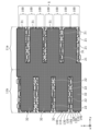
- FIG. 2 is a plan view of the power generation element of the battery according to the first embodiment, viewed from the side.
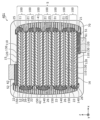
- FIG. 3 is another plan view of the power generating element of the battery according to Embodiment 1, viewed from the side.
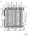
- FIG. 4A is a side view of the battery according to Embodiment 1.
- FIG. 4B is another side view of the battery according to Embodiment 1.
- FIG. 5A is a diagram for explaining the size of the conductive pieces according to the first embodiment.
- FIG. 5B is another diagram for explaining the size of the conductive pieces according to the first embodiment.
- FIG. 6 is a cross-sectional view of the battery according to the second embodiment.
- FIG. 7 is a side view of the battery according to the second embodiment.
- FIG. 8 is a cross-sectional view of a battery according to Embodiment 3.
- FIG. 9 is another cross-sectional view of the battery according to the third embodiment.
- FIG. 10 is a plan view of the power generating element of the battery according to Embodiment 3, viewed from the side.
- FIG. 11 is a side view of the battery according to the third embodiment.
- FIG. 12 is a cross-sectional view of a battery according to Embodiment 4.
- FIG. 13 is a cross-sectional view of a battery according to Embodiment 5.
- FIG. 14 is a flowchart showing a method for manufacturing a battery according to an embodiment.
- FIG. 14 is a flowchart showing a method for manufacturing a battery according to an embodiment.
- FIG. 15A is a cross-sectional view of an example of a unit cell according to an embodiment.
- FIG. 15B is a cross-sectional view of another example of the unit cell according to the embodiment.
- FIG. 15C is a cross-sectional view of another example of a unit cell according to an embodiment.
- the battery according to the first aspect of the present disclosure includes a plurality of battery cells each having an electrode layer, a counter electrode layer, and a solid electrolyte layer located between the electrode layer and the counter electrode layer, and a plurality of current collectors. , a power generation element in which the plurality of battery cells and the plurality of current collectors are stacked such that at least some of the plurality of battery cells are electrically connected in parallel, and a side surface of the power generation element.
- the plurality of current collectors include an electrode current collector electrically connected to the electrode layer, and a counter electrode current collector electrically connected to the counter electrode layer, and the plurality of conductive parts include:
- the counter electrode insulating layer includes at least a portion of the counter electrode current collector and the A conductive part different from the first electrode conductive part among the plurality of conductive parts is covered.
- a plurality of conductive parts including a first electrode conductive part are provided on the side surface of a power generation element whose energy density is increased by stacking a plurality of battery cells. By covering it, a high-performance battery can be realized.
- a connection structure with a current collector using a conductive part on the side of the power generation element it is important for the reliability of the battery that the connection between the current collector and the conductive part on the side of the power generation element is strong. Important for performance.
- alignment of the conductive part during construction is important.
- any of the conductive parts can be connected to the electrode current collector, and a connection between the conductive part and the electrode current collector can be formed.
- connection failure of the connection structure with the electrode current collector on the side surface of the power generation element it is possible to reduce connection failure of the connection structure with the electrode current collector on the side surface of the power generation element, and to suppress an increase in connection resistance.
- voltage loss caused by connection resistance on the side surface of the power generation element can be suppressed. Therefore, large current characteristics can be improved, and at the same time, heat generation in the connection structure with the current collector on the side surface of the power generation element can be suppressed, and strength deterioration of the connection structure due to thermal expansion and deformation can be suppressed.
- the internal stress of the first electrode conductive part can be dispersed and alleviated. Even if the first electrode conductive part thermally expands due to a rise in temperature during charging and discharging with a large current, embrittlement and peeling of the first electrode conductive part can be suppressed.
- the conductive parts are covered with the counter electrode insulating layer, so it is possible to insulate the conductive parts that do not contribute to connection with the electrode current collector from the electrode current collector, thereby preventing short circuits. It can be suppressed.
- a battery according to a second aspect of the present disclosure is a battery according to the first aspect, in which the plurality of conductive parts are covered with the counter electrode insulating layer in the first region, and the plurality of conductive parts are covered with the counter electrode current collector. a first counter electrode conductive portion connected to the body;
- the plurality of conductive parts include the first counter conductive part, short circuits via the first counter conductive part can be suppressed.
- the battery according to the third aspect of the present disclosure is the battery according to the first aspect or the second aspect, in which at least a part of the counter electrode insulating layer is covered in the first region, and the first electrode
- the device further includes an electrode conductive extraction layer electrically connected to the conductive portion.
- the electrode conductive extraction layer is electrically connected to the first electrode conductive part while suppressing short circuits by the counter electrode insulating layer, and the electrode conductive extraction layer can realize an extraction electrode of the electrode layer of the battery.
- a battery according to a fourth aspect of the present disclosure is a battery according to a third aspect, and is comprised of a group consisting of the first region, the plurality of conductive parts, the counter electrode insulating layer, and the electrode conductivity extraction layer. It has a cavity surrounded by an inner wall formed by at least one selected one.
- Such pores can alleviate internal stress and mechanical impact caused by expansion and contraction of the battery.
- a battery according to a fifth aspect of the present disclosure is a battery according to a third aspect or a fourth aspect, and includes a plurality of the electrode conductivity extraction layers, and the plurality of electrode conductivity extraction layers include the first electrode conductivity extraction layer. In a plan view of the region, they are arranged along a direction perpendicular to the stacking direction of the power generation elements.
- the internal stress of the electrode conductive extraction layer on the side surface of the battery can be reduced. Further, it is possible to disperse the impact when an external force is applied to the side surface of the battery.
- a battery according to a sixth aspect of the present disclosure is a battery according to any one of the first to fifth aspects, in which the counter electrode insulating layer has a stripe shape in a plan view of the first region. has.
- the counter electrode current collector stacked on the battery cell can be effectively covered by the striped counter electrode insulating layer.
- a battery according to a seventh aspect of the present disclosure is a battery according to any one of the first to sixth aspects, wherein the plurality of conductive parts are connected to the same electrode current collector.
- the first electrode conductive portion includes two or more of the first electrode conductive portions.
- connection area between the electrode current collector and the first electrode conductive part can be increased, and the connection resistance can be reduced.
- a battery according to an eighth aspect of the present disclosure is a battery according to any one of the first to seventh aspects, in which the plurality of conductive parts are regularly arranged.
- a battery according to a ninth aspect of the present disclosure is a battery according to any one of the first to eighth aspects, in which each of the plurality of conductive parts is The shape of is an ellipse, a rectangle, or a combination thereof.
- a battery according to a tenth aspect of the present disclosure is a battery according to any one of the first to ninth aspects, and in a plan view of the first region, in the stacking direction of the power generation elements.
- the length of the conductive portion is smaller than the length of the conductive portion in a direction perpendicular to the stacking direction of the power generation elements.
- a battery according to an eleventh aspect of the present disclosure is a battery according to any one of the first to tenth aspects, in which, in a plan view of the first region, the length of each of the plurality of conductive parts in the stacking direction of the power generating element is smaller than the sum of the thicknesses of each of the electrode layer, the solid electrolyte layer, and the counter electrode layer in the stacking direction of the power generating element.
- a battery according to a twelfth aspect of the present disclosure is a battery according to any one of the first to eleventh aspects, and in a plan view of the first region, in the stacking direction of the power generation elements.
- the length of each of the plurality of conductive parts is smaller than the thickness of the solid electrolyte layer in the stacking direction of the power generation element.
- a battery according to a thirteenth aspect of the present disclosure is a battery according to any one of the first to twelfth aspects, and in a plan view of the first region, in the stacking direction of the power generation elements.
- the length of each of the plurality of conductive parts is greater than the thickness of at least one of the electrode current collector and the counter electrode current collector.
- connection area between the conductive part and the current collector can be increased, and the connection resistance between the conductive part and the current collector can be reduced.
- a battery according to a fourteenth aspect of the present disclosure is a battery according to any one of the first to thirteenth aspects, wherein the plurality of conductive parts are connected to the first conductive portion on the side surface of the power generation element.
- the battery includes a second counter electrode conductive part connected to the counter electrode current collector in a second region different from the electrode current collector, and the battery includes a second counter electrode conductive part connected to the counter electrode current collector in a second region different from the electrode current collector.
- the device further includes an electrode insulating layer covering a conductive portion different from the second counter electrode conductive portion among the portions.
- a plurality of conductive parts including a second counter electrode conductive part are provided on the side surface of the power generation element whose energy density is increased by stacking a plurality of battery cells, and the electrode insulating layer covers some of the conductive parts.
- the electrode insulating layer covers some of the conductive parts.
- any of the conductive parts can be connected to the counter electrode current collector, and a connection between the conductive part and the counter electrode current collector can be formed.
- connection failures in the connection structure with the counter electrode current collector on the side surface of the power generation element can be reduced, and an increase in connection resistance can be suppressed.
- voltage loss caused by connection resistance on the side surface of the power generation element can be suppressed. Therefore, large current characteristics can be improved, and at the same time, heat generation in the connection structure with the current collector on the side surface of the power generation element can be suppressed, and strength deterioration of the connection structure due to thermal expansion and deformation can be suppressed.
- the conductive parts are covered with the electrode insulating layer, so it is possible to insulate the conductive parts that do not contribute to connection with the counter electrode current collector and the counter electrode current collector, thereby preventing short circuits. It can be suppressed.
- a battery according to a fifteenth aspect of the present disclosure is a battery according to a fourteenth aspect, in which the plurality of conductive parts are covered with the electrode insulating layer in the second region, and the electrode current collector It includes a second electrode conductive portion connected to the body.
- the plurality of conductive parts include the second electrode conductive part, short circuits via the second electrode conductive part can be suppressed.
- a battery according to a sixteenth aspect of the present disclosure is a battery according to the fourteenth aspect or the fifteenth aspect, in which the second region covers at least a part of the electrode insulating layer, and the second counter electrode
- the device further includes a counter electrode conductive extraction layer electrically connected to the conductive portion.
- the counter electrode conductive extraction layer is electrically connected to the second counter electrode conductive part while suppressing short circuits by the electrode insulating layer, and the counter electrode conductive extraction layer can realize an extraction electrode of the counter electrode layer of the battery.
- a battery according to a seventeenth aspect of the present disclosure is a battery according to a sixteenth aspect, and includes a plurality of the counter electrode conductive extraction layers, and the plurality of counter electrode conductive extraction layers are arranged in a plan view of the second region. , they are arranged along a direction perpendicular to the stacking direction of the power generating elements.
- the internal stress of the counter electrode conductive extraction layer on the side surface of the battery can be reduced. Further, it is possible to disperse the impact when an external force is applied to the side surface of the battery.
- a battery according to an eighteenth aspect of the present disclosure is a battery according to the sixteenth aspect or seventeenth aspect, in which at least a part of the counter electrode insulating layer is covered in the first region, and the first electrode an electrode conductive extraction layer electrically connected to the conductive part; an electrode current collection terminal provided on one main surface of the power generation element and electrically connected to the electrode conduction extraction layer; and the other side of the power generation element. and a counter electrode current collector terminal provided on the main surface of the electrode and electrically connected to the counter electrode conductive extraction layer.
- the two current collecting terminals with different polarities used for external connections etc. are placed apart from each other, so it is possible to suppress the occurrence of short circuits.
- the battery according to the 19th aspect of the present disclosure is the battery according to the 16th or 17th aspect, and includes, in the first region, an electrode conductive extraction layer that covers at least a portion of the counter electrode insulating layer and is electrically connected to the first electrode conductive portion, an electrode current collecting terminal provided on one main surface of the power generating element and electrically connected to the electrode conductive extraction layer, and a counter electrode current collecting terminal provided on the one main surface and electrically connected to the counter electrode conductive extraction layer.
- two current collecting terminals with different polarities used for external connections etc. are provided on the same main surface, making it easy to mount the battery. Further, for example, the shape and arrangement of the current collecting terminal can be adjusted according to the wiring layout of the mounting board, so that the degree of freedom in connection with the mounting board can be increased.
- the battery according to the 20th aspect of the present disclosure is the battery according to the 18th or 19th aspect, and further includes a sealing member that exposes a portion of the counter electrode current collector terminal and a portion of the electrode current collector terminal, and seals the power generating element, the multiple conductive parts, the electrode conductive extraction layer, and the counter electrode conductive extraction layer.
- the power generation element can be protected from outside air and water, so the reliability of the battery can be further improved.
- a battery according to a twenty-first aspect of the present disclosure is a battery according to any one of the fourteenth to twentieth aspects, in which the first region and the second region are located in the same plane on the side surface of the power generating element.
- a plurality of conductive parts including both the first electrode conductive part and the second counter electrode conductive part are formed on the same plane, so that the manufacturing process of the plurality of conductive parts can be simplified.
- a battery according to a twenty-second aspect of the present disclosure is a battery according to any one of the first to twenty-first aspects, and the counter electrode insulating layer includes a resin.
- the impact resistance of the battery can be improved. Furthermore, stress applied to the battery due to temperature changes in the battery or due to expansion and contraction during charging and discharging can be alleviated.
- the method for manufacturing a battery according to the twenty-third aspect of the present disclosure includes a plurality of battery cells each having an electrode layer, a counter electrode layer, and a solid electrolyte layer located between the electrode layer and the counter electrode layer; and a power generation element in which the plurality of battery cells and the plurality of current collectors are stacked so that at least some of the plurality of battery cells are electrically connected in parallel, Each of the plurality of battery cells is sandwiched between two adjacent current collectors among the plurality of current collectors, and the plurality of current collectors are electrode current collectors electrically connected to the electrode layer.
- the method comprising: forming a plurality of discrete conductive parts on a side surface of the power generation element, forming a plurality of conductive parts, the plurality of conductive parts including a first electrode conductive part connected to the electrode current collector in a first region of a side surface of the power generation element; forming a counter electrode insulating layer covering at least a part of the counter electrode current collector and a part of the plurality of conductive parts different from the first electrode conductive part.
- a method for manufacturing a battery according to a twenty-fourth aspect of the present disclosure is a method for manufacturing a battery according to a twenty-third aspect, in which at least a portion of the counter electrode insulating layer is covered in the first region; The method further includes forming an electrode conductive extraction layer electrically connected to the one electrode conductive portion.
- each figure is a schematic diagram and is not necessarily strictly illustrated. Therefore, for example, the scales and the like in each figure do not necessarily match. Further, in each figure, substantially the same configurations are denoted by the same reference numerals, and overlapping explanations will be omitted or simplified.
- the x-axis, y-axis, and z-axis indicate three axes of a three-dimensional orthogonal coordinate system.
- the x-axis and the y-axis are directions parallel to the first side of the rectangle and the second side perpendicular to the first side, respectively.
- the z-axis is the stacking direction of a plurality of battery cells included in the power generation element.
- the "layering direction" of the power generation element corresponds to the normal direction of the main surface of each layer of the current collector and the battery cell.
- “planar view” refers to a view from a direction perpendicular to the main surface, unless otherwise specified.
- ⁇ a planar view of a certain surface (or a certain area)'' such as ⁇ a planar view of the side'', it refers to the situation when the ⁇ certain surface (or a certain area)'' is viewed from the front. Say something.
- the terms “above” and “below” do not refer to the upward direction (vertically upward) and downward direction (vertically downward) in an absolute spatial sense, but are used as terms defined by a relative positional relationship based on the stacking order in a stacked configuration. Furthermore, the terms “above” and “below” are applied not only to cases where two components are arranged with a gap between them and another component exists between the two components, but also to cases where two components are arranged in close contact with each other and are in contact. In the following explanation, the negative side of the z axis is referred to as “below” or “lower side”, and the positive side of the z axis is referred to as “above” or "upper side”.
- the expression “to cover A” means to cover at least a portion of “A” unless otherwise specified. That is, the expression “to cover A” includes not only “to cover all of A” but also to “to cover only a part of A”.
- “A” is, for example, a predetermined member such as a layer or a terminal, and a side surface and main surface of the predetermined member.
- ordinal numbers such as “first” and “second” do not mean the number or order of components, unless otherwise specified, and to avoid confusion between similar components, It is used to distinguish between elements.
- FIG. 1 is a cross-sectional view of a battery 1 according to the present embodiment.
- FIG. 2 is a plan view of the power generation element 5 of the battery 1 according to the present embodiment, viewed from the side (positive side in the x-axis direction).
- FIG. 3 is another plan view of the power generation element 5 of the battery 1 according to the present embodiment, viewed from the side (positive side in the x-axis direction).
- FIG. 4A is a side view of battery 1 according to this embodiment.
- FIG. 4B is another side view of the battery 1 according to this embodiment.
- FIG. 1 represents a cross section taken along line II shown in FIG. 4A.
- FIGS. 2 and 3 show a state in which the battery 1 is in the middle of being manufactured.
- FIG. 1 represents a cross section taken along line II shown in FIG. 4A.
- FIGS. 2 and 3 show a state in which the battery 1 is in the middle of being manufactured.
- FIG. 1 represents a cross section taken along line II shown in FIG
- FIG. 2 is a diagram when the counter electrode insulating layer 31 and the electrode conductive extraction layer 41 are removed from the battery 1.
- FIG. 3 is a diagram when the electrode conductive extraction layer 41 is removed from the battery 1.
- the battery 1 is manufactured, for example, through the states shown in FIGS. 2 and 3 in this order.
- FIG. 4A is a plan view of the battery 1 when viewed from the positive side in the x-axis direction.
- FIG. 4B is a plan view of the battery 1 viewed from the negative side in the x-axis direction.
- the battery 1 includes a power generation element 5, a plurality of conductive pieces 20, a counter electrode insulating layer 31, an electrode insulating layer 32, an electrode conductive extraction layer 41, and a counter electrode conductive extraction layer 42. , an electrode current collecting terminal 51 and a counter electrode current collecting terminal 52.
- the battery 1 is, for example, an all-solid-state battery.
- the conductive piece 20 is an example of a conductive part.
- all the pieces with the dot pattern in the area surrounded by the rectangle of the two-dot chain line are the conductive pieces 20.
- the power generation element 5 has a structure in which a plurality of battery cells 100 and a plurality of current collectors are stacked along the thickness direction of the plurality of battery cells 100. Such a laminated structure allows the energy density of the battery 1 to be increased.
- the shape of the power generation element 5 in plan view is, for example, rectangular. That is, the general shape of the power generation element 5 is a flat rectangular parallelepiped.
- flatness means that the thickness (that is, the length in the z-axis direction) is shorter than each side of the main surface (that is, the length in each of the x-axis direction and the y-axis direction) or the maximum width.
- the shape of the power generation element 5 in plan view may be any other polygonal shape such as a square, hexagonal or octagonal shape, or may be circular or elliptical.
- the outer edge of the power generation element 5 in plan view may have unevenness.
- each layer is exaggerated in cross-sectional views such as FIG. 1 and side plan views such as FIGS. 2 to 4B in order to make the layered structure of the power generation element 5 easier to understand. It is illustrated as follows.
- the power generating element 5 includes a side surface and a main surface 15 and a main surface 16.
- the side surface of the power generating element 5 is a surface that connects the main surface 15 and the main surface 16.
- the general shape of the power generating element 5 is a rectangular parallelepiped, and the side surface of the power generating element 5 includes four side surfaces including the side surface 11 and the side surface 12 as individual surfaces.
- each of the four side surfaces of the power generating element 5, the main surface 15 and the main surface 16 are flat surfaces. This improves the mechanical strength of the end of the power generating element 5 without the entire or part of the battery cell 100 protruding from the end of the power generating element 5.
- the side surface 11 is an example of a first region of the side surface of the power generating element 5.
- the side surface 12 is an example of a second region of the side surface of the power generating element 5.
- the side surface of the power generating element 5 may be a curved surface or a combination of a flat surface and a curved surface.
- the side surfaces 11 and 12 are opposite each other and parallel to each other.
- the other two side surfaces of the power generation element 5 other than the side surface 11 and the side surface 12 are opposite to each other and parallel to each other. Further, the other two side surfaces are surfaces perpendicular to the side surface 11 and the side surface 12.
- the four side surfaces of the power generation element 5 are erected from each side of the main surface 15 and the main surface 16 perpendicularly to the main surface 15 and the main surface 16.
- Each of the four side surfaces of the power generation element 5 is, for example, a cut surface. Thereby, the area of each layer of the battery cell 100 is determined accurately by cutting, so that variations in the capacity of the battery 1 can be reduced and accuracy of battery capacity can be improved.
- the main surface 15 and the main surface 16 are opposite to each other and parallel to each other.
- the main surface 15 is the uppermost surface of the power generation element 5.
- the main surface 16 is the lowest surface of the power generation element 5.
- the main surface 15 and the main surface 16 each have a larger area than any of the four side surfaces of the power generation element 5, for example.
- the power generation element 5 includes a plurality of battery cells 100 and a plurality of current collectors.
- the plurality of current collectors include an electrode current collector 140 electrically connected to the electrode layer 110 and a counter electrode current collector 150 electrically connected to the counter electrode layer 120.
- each of the plurality of current collectors is either electrode current collector 140 or counter electrode current collector 150.
- the battery cell 100 is the minimum configuration of a power generation section of a battery, and is also referred to as a unit cell. Further, the battery cell 100 and the current collector stacked on the battery cell 100 may be collectively referred to as a unit cell.
- the plurality of battery cells 100 are stacked so as to be electrically connected in parallel.
- the plurality of battery cells 100 are stacked such that all the battery cells 100 included in the power generation element 5 are electrically connected in parallel.
- the number of battery cells 100 included in the power generation element 5 is seven, but the number is not limited to this.
- the number of battery cells 100 included in the power generation element 5 may be an even number such as 2 or 4, or an odd number such as 3 or 5.
- Each of the multiple battery cells 100 includes an electrode layer 110, a counter electrode layer 120, and a solid electrolyte layer 130.
- the electrode layer 110 and the counter electrode layer 120 each include an active material, and are also referred to as an electrode active material layer and a counter electrode active material layer.
- the electrode layer 110, the solid electrolyte layer 130, and the counter electrode layer 120 are stacked in this order along the z-axis.
- the electrode layer 110 is one of the positive electrode layer and the negative electrode layer of the battery cell 100.
- the counter electrode layer 120 is the other of the positive electrode layer and the negative electrode layer of the battery cell 100.
- the case where the electrode layer 110 is a negative electrode layer and the counter electrode layer 120 is a positive electrode layer will be described as an example.
- Each of the plurality of battery cells 100 of the power generation element 5 includes two adjacent current collectors among the plurality of current collectors (specifically, one electrode current collector 140 and one counter electrode current collector 150). sandwiched between. Further, two adjacent battery cells 100 among the plurality of battery cells 100 are stacked via one of the plurality of current collectors.
- the configurations of the plurality of battery cells 100 are substantially the same.
- the order of the layers constituting the battery cells 100 is reversed.
- the plurality of battery cells 100 are stacked in a line along the z-axis, with the arrangement order of each layer constituting the battery cell 100 being alternated. Therefore, two adjacent battery cells 100 are arranged such that their electrode layers 110 or counter electrode layers 120 face each other.
- An electrode current collector 140 is arranged between the facing electrode layers 110, and a counter electrode current collector 150 is arranged between the facing counter electrode layers 120.
- an electrode current collector 140 is laminated on the electrode layer 110 without intervening the solid electrolyte layer 130, and a counter electrode current collector 150 is laminated on the counter electrode layer 120 without intervening the solid electrolyte layer 130.
- the electrode current collectors 140 and the counter electrode current collectors 150 are arranged alternately one by one along the z-axis direction.
- the battery 1 is a parallel-connected stacked battery in which a plurality of battery cells 100 and a plurality of current collectors are stacked and integrated.
- the lowest and highest parts of the power generating element 5 serve as layers and current collectors of different polarities, respectively.
- At least one of the lowermost portion and the uppermost portion of the power generation element 5 is composed of an electrode layer 110 and an electrode current collector 140, for example. Note that when the number of battery cells 100 is an even number, the lowermost part and the uppermost part of the power generating element 5 serve as a layer and a current collector of the same polarity, respectively.
- the plurality of current collectors includes a plurality of electrode current collectors 140 and a plurality of counter electrode current collectors 150. Note that when only two battery cells 100 are stacked, one of the electrode current collector 140 and the counter electrode current collector 150 becomes one, for example, the counter electrode current collector 150 becomes one.
- the plurality of electrode current collectors 140 and the plurality of counter electrode current collectors 150 are each exposed on the side surface of the power generation element 5 without being covered by the battery cell 100.
- the electrode current collectors 140 are not in direct contact with each other, and in order to connect the plurality of battery cells 100 in parallel, the plurality of electrode current collectors 140 are connected via the first electrode conductive piece 21 and the electrode conductive extraction layer 41. electrically connected.
- the counter electrode current collectors 150 are not in direct contact with each other, and in order to connect the plurality of battery cells 100 in parallel, the plurality of counter electrode current collectors 150 connect the second counter electrode conductive pieces 22 and the counter electrode conductive extraction layer 42. electrically connected via.
- the electrode current collector 140 and the counter electrode current collector 150 are each conductive foil-like, plate-like, or mesh-like members.
- the electrode current collector 140 and the counter electrode current collector 150 may each be, for example, a conductive thin film.
- the electrode current collector 140 and the counter electrode current collector 150 are each made of one metal foil.
- the electrode current collector 140 and the counter electrode current collector 150 may each have a multilayer structure of a plurality of current collecting layers made of a plurality of metal foils or the like. In this case, the plurality of current collecting layers are stacked directly or via an intermediate layer.
- Electrode current collector 140 and counter electrode current collector 150 may be formed using different materials.
- each of the electrode current collector 140 and the counter electrode current collector 150 is, for example, 5 ⁇ m or more and 200 ⁇ m or less, but is not limited thereto.
- the electrode layer 110 is in contact with the main surface of the electrode current collector 140.
- the electrode layer 110 is in contact with each of the two main surfaces.
- the electrode layer 110 is in contact with only one of the two main surfaces (specifically, the upper surface).
- the electrode current collector 140 may include a connection layer that is a layer containing a conductive material and provided in a portion that is in contact with the electrode layer 110.
- the counter electrode layer 120 is in contact with the main surface of the counter electrode current collector 150.
- the counter electrode layer 120 is in contact with each of the two main surfaces.
- the counter electrode layer 120 is in contact with only one of the two main surfaces (specifically, the lower surface).
- the counter electrode current collector 150 may include a connection layer that is a layer containing a conductive material and is provided in a portion in contact with the counter electrode layer 120.
- the electrode layer 110 is arranged on the main surface of the electrode current collector 140.
- the electrode layer 110 includes, for example, a negative electrode active material as an electrode material. Electrode layer 110 is placed opposite counter electrode layer 120 .
- the negative electrode active material contained in the electrode layer 110 may be, for example, graphite, metallic lithium, or other negative electrode active material.
- As the material for the negative electrode active material various materials capable of extracting and inserting ions such as lithium (Li) or magnesium (Mg) may be used.
- a solid electrolyte such as an inorganic solid electrolyte may be further used.
- an inorganic solid electrolyte for example, a sulfide solid electrolyte or an oxide solid electrolyte can be used.
- a sulfide solid electrolyte for example, a mixture of lithium sulfide (Li 2 S) and diphosphorus pentasulfide (P 2 S 5 ) can be used.
- a conductive agent such as acetylene black, a binding binder such as polyvinylidene fluoride, or the like may be further used.
- the electrode layer 110 is produced by applying a paste-like paint in which the material contained in the electrode layer 110 is kneaded together with a solvent, for example, onto the main surface of the electrode current collector 140 and drying it.
- the electrode current collector 140 also referred to as an electrode plate coated with the electrode layer 110 may be pressed after drying.
- the thickness of the electrode layer 110 is, for example, 5 ⁇ m or more and 300 ⁇ m or less, but is not limited thereto.
- the counter electrode layer 120 is arranged on the main surface of the counter electrode current collector 150.
- the counter electrode layer 120 is a layer containing a positive electrode material such as an active material.
- the positive electrode material is a material that constitutes the opposite electrode of the negative electrode material.
- the counter electrode layer 120 includes, for example, a positive electrode active material.
- Examples of the positive electrode active material contained in the counter electrode layer 120 include lithium cobaltate composite oxide (LCO), lithium nickelate composite oxide (LNO), lithium manganate composite oxide (LMO), lithium-manganese-nickel Positive electrode active materials such as composite oxide (LMNO), lithium-manganese-cobalt composite oxide (LMCO), lithium-nickel-cobalt composite oxide (LNCO), and lithium-nickel-manganese-cobalt composite oxide (LNMCO) can be used.
- As the material of the positive electrode active material various materials that can remove and insert ions such as Li or Mg can be used.
- a solid electrolyte such as an inorganic solid electrolyte may be further used.
- a sulfide solid electrolyte or an oxide solid electrolyte can be used.
- a mixture of Li 2 S and P 2 S 5 can be used.
- the surface of the positive electrode active material may be coated with a solid electrolyte.
- a conductive agent such as acetylene black, a binding binder such as polyvinylidene fluoride, etc. may further be used.
- the counter electrode layer 120 is produced by applying a paste-like paint in which the material contained in the counter electrode layer 120 is kneaded together with a solvent, for example, onto the main surface of the counter electrode current collector 150 and drying it.
- the counter electrode current collector 150 also referred to as a counter electrode plate coated with the counter electrode layer 120 may be pressed after drying.
- the thickness of the counter electrode layer 120 is, for example, 5 ⁇ m or more and 300 ⁇ m or less, but is not limited thereto.
- the solid electrolyte layer 130 is arranged between the electrode layer 110 and the counter electrode layer 120. Solid electrolyte layer 130 is in contact with each of electrode layer 110 and counter electrode layer 120.
- the solid electrolyte layer 130 has, for example, lithium ion conductivity.
- Solid electrolyte layer 130 is a layer containing an electrolyte material. As the electrolyte material, generally known electrolytes for batteries can be used.
- the thickness of the solid electrolyte layer 130 may be 5 ⁇ m or more and 300 ⁇ m or less, or 5 ⁇ m or more and 100 ⁇ m or less.
- the solid electrolyte layer 130 includes a solid electrolyte.
- a solid electrolyte such as an inorganic solid electrolyte can be used.
- an inorganic solid electrolyte a sulfide solid electrolyte or an oxide solid electrolyte can be used.
- a sulfide solid electrolyte for example, a mixture of Li 2 S and P 2 S 5 can be used.
- the solid electrolyte layer 130 may contain a binder such as polyvinylidene fluoride.
- the electrode layer 110, the counter electrode layer 120, and the solid electrolyte layer 130 are maintained in a parallel plate shape. Thereby, it is possible to suppress the occurrence of cracks or collapse due to curvature. Note that the electrode layer 110, the counter electrode layer 120, and the solid electrolyte layer 130 may be smoothly curved together.
- the electrode layer 110, the solid electrolyte layer 130, and the counter electrode layer 120 each have the same shape and size, and their respective contours match.
- the multiple battery cells 100 are substantially the same size as one another.
- the multiple battery cells 100, the multiple electrode current collectors 140, and the multiple counter electrode current collectors 150 each have the same shape and size, and their respective contours match.
- FIGS. 1 to 4B are plan views of the side surface 11 of the power generation element 5, respectively.
- FIG. 4B is a plan view of the side surface 12 of the power generation element 5 when viewed from above. Note that in FIGS. 2 to 4B, each configuration shown in the plan view is given the same shading as that of each configuration shown in the cross section of FIG. 1. This also applies to subsequent plan views.
- the battery 1 includes a plurality of discrete conductive pieces 20 provided on the side surfaces (specifically, the side surfaces 11 and 12) of the power generation element 5.
- the plurality of conductive pieces 20 are minute conductive members arranged on the side surface of the power generation element 5.
- Each of the plurality of conductive pieces 20 is, for example, in the form of a film or a plate whose thickness direction is perpendicular to the side surface of the power generation element 5 on which the conductive pieces 20 are arranged. Thereby, the connection area between the conductive piece 20 and the side surface of the power generation element 5 can be increased.
- the plurality of conductive pieces 20 may have a shape other than a film shape or a plate shape, such as a particle shape or a rod shape.
- the shape of the plurality of conductive pieces 20 is, for example, an ellipse, a rectangle, or a combination thereof. This makes it easy to form the conductive pieces 20.
- the plurality of conductive pieces 20 can be easily formed using a pattern mask or an inkjet method. Moreover, it is easy to increase the connection strength between the conductive pieces 20 and the current collector.
- the plurality of conductive pieces 20 have, for example, substantially the same shape and size, but may include conductive pieces 20 with different shapes and sizes. Note that the shape of the plurality of conductive pieces 20 in plan view is not particularly limited, and may be a shape other than the above, such as a polygon.
- the number of the plurality of conductive pieces 20 formed on the side surface 11 is greater than the number of battery cells 100 that the power generation element 5 has.
- the number of the plurality of conductive pieces 20 formed on the side surface 11 may be twice or more, three times or more, four times or more as the number of current collectors that the power generation element 5 has. It's okay.
- a connection with each conductive piece 20 is formed for each of the plurality of current collectors. , it becomes easier to secure the connection area between the conductive pieces 20 and the current collector.
- the upper limit of the number of the plurality of conductive pieces 20 formed on the side surface 11 may be set as appropriate depending on the size of the power generation element 5 and the conductive pieces 20, etc.
- the number of conductive pieces 20 is, for example, 1000 times or less the number of current collectors that the power generation element 5 has.
- the number of the plurality of conductive pieces 20 formed on the side surface 11 may be more than 1000 times the number of current collectors that the power generation element 5 has.
- the number of the plurality of conductive pieces 20 formed on the side surface 11 is 50 or less per 1 mm 2 .
- Each of the plurality of conductive pieces 20 includes, for example, only at least one of the electrode layer 110, the electrode current collector 140, the counter electrode layer 120, and the counter electrode current collector 150, or , contacts only at least one of the counter electrode layer 120 and the counter electrode current collector 150. That is, each of the plurality of conductive pieces 20 is not electrically connected to both the electrode layer 110 and the electrode current collector 140 and the counter electrode layer 120 and the counter electrode current collector 150.
- the plurality of conductive pieces 20 are regularly arranged on the side surface 11.
- the plurality of conductive pieces 20 form, for example, rows or lattice points when viewed from the side surface 11 in plan. This makes it possible to design the arrangement of the plurality of conductive pieces 20 on the side surface 11 so that the conductive pieces 20 and the electrode current collector 140 are effectively connected.
- the plurality of conductive pieces 20 are arranged to form a plurality of rows along the stacking direction, for example, in a plan view of the side surface 11.
- the plurality of rows are arranged along a direction perpendicular to the stacking direction in a plan view of the side surface 11.
- the plurality of rows are arranged at equal intervals in a plan view of the side surface 11.
- the plurality of rows include rows in which the positional relationships of the conductive pieces 20 in the stacking direction are different from each other.
- the positional relationship of the conductive pieces 20 in the stacking direction has periodicity, and rows in which the positional relationship of the conductive pieces 20 in the stacking direction are the same are arranged in regular columns.
- the plurality of rows may have curved or bent portions such as a wavy line shape or a zigzag shape.
- the conductive pieces 20 are arranged at equal intervals.
- the number of conductive pieces 20 included in each of the plurality of columns is, for example, greater than the number of current collectors that the power generation element 5 has.
- the number of conductive pieces 20 included in each of the plurality of rows may be twice or more, or three times or more, the number of current collectors that the power generation element 5 has.
- the upper limit of the number of conductive pieces 20 included in each of the plurality of columns may be set appropriately depending on the size of the power generation element 5 and the conductive pieces 20, but the number of conductive pieces 20 included in each of the plurality of columns may be set appropriately.
- the number of conductive pieces 20 included is, for example, 10 times or less the number of current collectors that the power generation element 5 has.
- the plurality of conductive pieces 20 are arranged, for example, in a plan view of the side surface 11 to form a plurality of inclined rows that are inclined with respect to the direction (y-axis direction) orthogonal to the stacking direction of the power generation elements 5.
- Ru In a plan view of the side surface 11, the direction perpendicular to the stacking direction of the power generation element 5 is also the direction in which each layer and each current collector of the power generation element 5 extend.
- the plurality of inclined rows have an inclination angle larger than the angle at which the diagonal line of the battery cell 100 is inclined with respect to a direction perpendicular to the direction in which the power generation elements 5 are stacked in the direction in which the power generation elements 5 are stacked.
- the plurality of inclined rows are formed by laminating the power generating elements 5 at an inclination angle smaller than the angle at which the diagonal line of the power generating elements is inclined with respect to a direction perpendicular to the laminating direction of the power generating elements 5 in a plan view of the side surface 11. Tilt with respect to the direction perpendicular to the direction.
- the plurality of inclined rows are arranged at equal intervals in a plan view of the side surface 11.
- the number of the plurality of inclined rows is greater than the number of current collectors that the power generation element 5 has.
- the number of the plurality of inclined rows may be twice or more, or three times or more, the number of current collectors that the power generation element 5 has. Further, the upper limit of the number of the plurality of inclined rows may be appropriately set according to the size of the power generation element 5 and the conductive pieces 20, etc., but the number of the plurality of inclined rows is, for example, The number of current collectors is 10 times or less. Further, in a plan view of the side surface 11, the conductive pieces 20 are arranged at equal intervals in each of the plurality of inclined rows.
- the plurality of conductive pieces 20 are arranged, for example, at positions corresponding to lattice points of a predetermined lattice when viewed from the side surface 11 in plan.
- the predetermined lattice include an orthorhombic lattice, a rhombic lattice, a centered rectangular lattice, an isosceles triangular lattice, a hexagonal lattice, an equilateral triangular lattice, a square lattice, a rectangular lattice, a primitive rectangular lattice, a parallel body lattice, and a distorted oblique lattice.
- the predetermined grid is not limited thereto.
- the plurality of conductive pieces 20 are also arranged on the side surface 12, for example, in the same layout as the side surface 11 described above.
- a plurality of conductive pieces 20 are arranged on the side surface 12 in the layout shown in FIG.
- the layout of the plurality of conductive pieces 20 is not limited to the example shown in FIG. 2, and can be designed as appropriate based on the contents explained above. Further, some of the plurality of conductive pieces 20 may be arranged regularly. Further, all of the plurality of conductive pieces 20 may be randomly arranged.
- the battery 1 may also have voids formed between adjacent conductive pieces 20.
- the voids are provided, for example, in place of any of the counter electrode insulating layer 31, the electrode conductive extraction layer 41, the electrode insulating layer 32, and the counter electrode conductive extraction layer 42 between adjacent conductive pieces 20.
- the voids are provided by not forming any of the counter electrode insulating layer 31, the electrode conductive extraction layer 41, the electrode insulating layer 32, and the counter electrode conductive extraction layer 42 between adjacent conductive pieces 20. This allows the voids to function as a buffer space against internal stress and mechanical shock due to expansion and contraction of the battery 1.
- the position at which the voids are formed is not limited to the above example, and may be formed anywhere on the outside of the side surface 11 and the outside of the side surface 12 of the power generating element 5 in the battery 1.
- the voids may be voids surrounded by an inner wall formed by at least one selected from the group consisting of the side surface 11, the multiple conductive pieces 20, the electrode conductive extraction layer 41, and the counter electrode insulating layer 31.
- the void may also be a void surrounded by an inner wall formed by at least one selected from the group consisting of the side surface 12, the plurality of conductive pieces 20, the counter electrode conductive extraction layer 42, and the electrode insulating layer 32.
- the plurality of conductive pieces 20 include a plurality of first electrode conductive pieces 21 and a plurality of first counter electrode conductive pieces 25.
- the first electrode conductive piece 21 is an example of a first electrode conductive part.
- the first counter electrode conductive piece 25 is an example of a first counter electrode conductive part.
- Each of the plurality of first electrode conductive pieces 21 is a conductive piece 20 connected to the electrode current collector 140 on the side surface 11. Further, the plurality of first electrode conductive pieces 21 are in contact with the electrode conductivity extraction layer 41 on the side surface 11 and are covered by the electrode conductivity extraction layer 41 . Note that the plurality of first electrode conductive pieces 21 may include first electrode conductive pieces 21 that are not covered with the electrode conductive extraction layer 41.
- Each of the plurality of first electrode conductive pieces 21 covers the electrode current collector 140 on the side surface 11. Further, the plurality of first electrode conductive pieces 21 are connected to each of the plurality of electrode current collectors 140 of the power generation element 5 in contact with each other on the side surface 11, and cover each of the plurality of electrode current collectors 140. . Each of the plurality of first electrode conductive pieces 21 is connected to any one of the plurality of electrode current collectors 140. Further, each of the plurality of electrode current collectors 140 is connected to at least one first electrode conductive piece 21. Each first electrode conductive piece 21 is not connected to two or more electrode current collectors 140 on the side surface 11 .
- Each of the plurality of first electrode conductive pieces 21 overlaps with one of the plurality of electrode current collectors 140 in a plan view of the side surface 11. Further, each of the plurality of first electrode conductive pieces 21 is connected to and contacts the electrode layer 110 on the side surface 11, and covers the electrode layer 110. Each of the plurality of first electrode conductive pieces 21 is not in contact with each of the plurality of counter electrode current collectors 150 of the power generation element 5 and the counter electrode layer 120 of each of the plurality of battery cells 100. Further, the plurality of first electrode conductive pieces 21 may include a first electrode conductive piece 21 that contacts the solid electrolyte layer 130 and covers the solid electrolyte layer 130 on the side surface 11 . Further, the plurality of first electrode conductive pieces 21 may include a first electrode conductive piece 21 that is not in contact with the electrode layer 110 on the side surface 11.
- the plurality of first electrode conductive pieces 21 include two or more first electrode conductive pieces 21 connected to the same electrode current collector 140 on the side surface 11. Thereby, the connection area between the electrode current collector 140 and the first electrode conductive piece 21 can be further increased.
- the electrical connection structure with the electrode current collector 140 on the side surface 11 becomes strong.
- the electrode conductive extraction layer 41 is connected via the first electrode conductive piece 21 rather than being directly connected to each of the plurality of electrode current collectors 140 on the side surface 11. 21 and the electrode current collector 140 can be easily brought into contact with each other, and the connection strength can be increased.
- the plurality of conductive pieces 20 are formed discretely on the side surface 11, the internal stress of the first electrode conductive pieces 21 can be dispersed and relaxed. Further, even if the first electrode conductive pieces 21 thermally expand due to temperature rise during charging and discharging with a large current, embrittlement and peeling of the first electrode conductive pieces 21 can be suppressed.
- Each of the plurality of first counter electrode conductive pieces 25 is a conductive piece 20 connected to the counter electrode current collector 150 on the side surface 11. Further, the plurality of first counter electrode conductive pieces 25 are in contact with the counter electrode insulating layer 31 on the side surface 11 and are covered by the counter electrode insulating layer 31 . Note that the plurality of first counter electrode conductive pieces 25 may include first counter electrode conductive pieces 25 that are not covered with the counter electrode insulating layer 31.
- Each of the plurality of first counter electrode conductive pieces 25 covers the counter electrode current collector 150 on the side surface 11. Further, the plurality of first counter electrode conductive pieces 25 are connected in contact with each of the plurality of counter electrode current collectors 150 of the power generation element 5 on the side surface 11, and cover each of the plurality of counter electrode current collectors 150. . Each of the plurality of first counter electrode conductive pieces 25 is connected to any one of the plurality of counter electrode current collectors 150. Furthermore, each of the plurality of counter electrode current collectors 150 is connected to at least one first counter electrode conductive piece 25 . Each first counter electrode conductive piece 25 is not connected to two or more counter electrode current collectors 150 on the side surface 11 . Each of the plurality of first counter electrode conductive pieces 25 is not in contact with each of the plurality of electrode current collectors 140 of the power generation element 5 and the electrode layer 110 of each of the plurality of battery cells 100.
- the plurality of conductive pieces 20 include the first counter electrode conductive pieces 25 connected to the counter electrode current collector 150 at the side surface 11 by being formed without alignment, etc. Since the conductive pieces 25 are covered with the counter electrode insulating layer 31, short circuits via the first counter electrode conductive pieces 25 are suppressed. Therefore, both high productivity and high reliability of the battery 1 can be achieved.
- the plurality of conductive pieces 20 include a plurality of second counter electrode conductive pieces 22 and a plurality of second electrode conductive pieces 26.
- the second counter electrode conductive piece 22 is an example of a second counter electrode conductive part.
- the second electrode conductive piece 26 is an example of a second electrode conductive part.
- Each of the plurality of second counter electrode conductive pieces 22 is a conductive piece 20 connected to a different counter electrode current collector 150 on the side surface 12. Further, the plurality of second counter electrode conductive pieces 22 are in contact with the counter electrode conductive extraction layer 42 on the side surface 12 and are covered by the counter electrode conductive extraction layer 42 . Note that the plurality of second counter electrode conductive pieces 22 may include second counter electrode conductive pieces 22 that are not covered with the counter electrode conductive extraction layer 42.
- Each of the plurality of second counter electrode conductive pieces 22 covers the counter electrode current collector 150 on the side surface 12. Further, the plurality of second counter electrode conductive pieces 22 are connected in contact with each of the plurality of counter electrode current collectors 150 of the power generation element 5 on the side surface 12, and cover each of the plurality of counter electrode current collectors 150. . Each of the plurality of second counter electrode conductive pieces 22 is connected to any one of the plurality of counter electrode current collectors 150. Furthermore, each of the plurality of counter electrode current collectors 150 is connected to at least one second counter electrode conductive piece 22 . Each second counter electrode conductive piece 22 is not connected to two or more counter electrode current collectors 150 on the side surface 12 .
- Each of the plurality of second counter electrode conductive pieces 22 overlaps with one of the plurality of counter electrode current collectors 150 in a plan view of the side surface 12. Further, each of the plurality of second counter electrode conductive pieces 22 is connected to and contacts the counter electrode layer 120 on the side surface 12, and covers the counter electrode layer 120. Each of the plurality of second counter electrode conductive pieces 22 is not in contact with each of the plurality of electrode current collectors 140 of the power generation element 5 and the electrode layer 110 of each of the plurality of battery cells 100. Further, the plurality of second counter electrode conductive pieces 22 may include a second counter electrode conductive piece 22 that contacts the solid electrolyte layer 130 and covers the solid electrolyte layer 130 on the side surface 12. Further, the plurality of second counter electrode conductive pieces 22 may include second counter electrode conductive pieces 22 that are not in contact with the counter electrode layer 120 on the side surface 12 .
- the plurality of second counter electrode conductive pieces 22 include two or more second counter electrode conductive pieces 22 connected to the same counter electrode current collector 150 on the side surface 12. Thereby, the connection area between the counter electrode current collector 150 and the second counter electrode conductive pieces 22 can be further increased.
- the second counter electrode conductive piece 22 is connected to the counter electrode collector 150 on the side surface 12, so that the electrical connection structure with the counter electrode collector 150 on the side surface 12 is strong.
- the connection strength can be increased.
- the multiple conductive pieces 20 are formed discretely on the side surface 12, the internal stress of the second counter electrode conductive piece 22 can be dispersed and relaxed.
- embrittlement and peeling of the second counter electrode conductive piece 22 can be suppressed.
- Each of the plurality of second electrode conductive pieces 26 is a conductive piece 20 connected to the electrode current collector 140 on the side surface 12. Furthermore, the plurality of second electrode conductive pieces 26 are in contact with the electrode insulating layer 32 on the side surface 12 and are covered by the electrode insulating layer 32 . Note that the plurality of second electrode conductive pieces 26 may include second electrode conductive pieces 26 that are not covered with the electrode insulating layer 32.
- Each of the plurality of second electrode conductive pieces 26 covers the electrode current collector 140 on the side surface 12. Further, the plurality of second electrode conductive pieces 26 are connected to each of the plurality of electrode current collectors 140 of the power generation element 5 in contact with each other on the side surface 12, and cover each of the plurality of electrode current collectors 140. . Each of the plurality of second electrode conductive pieces 26 is connected to any one of the plurality of electrode current collectors 140. Further, each of the plurality of electrode current collectors 140 is connected to at least one second electrode conductive piece 26. Each second electrode conductive piece 26 is not connected to two or more electrode current collectors 140 on the side surface 12 . Each of the plurality of second electrode conductive pieces 26 is not in contact with each of the plurality of counter electrode current collectors 150 of the power generation element 5 and the counter electrode layer 120 of each of the plurality of battery cells 100.
- the plurality of conductive pieces 20 include the second electrode conductive pieces 26 connected to the electrode current collector 140 at the side surface 12, such as by being formed without alignment; Since the conductive pieces 26 are covered with the electrode insulating layer 32, short circuits via the second electrode conductive pieces 26 are suppressed. Therefore, both high productivity and high reliability of the battery 1 can be achieved.
- the plurality of conductive pieces 20 are formed using a conductive resin material or the like.
- the conductive resin material includes, for example, a resin and a conductive material filled in the resin and made of metal particles or the like.
- the plurality of conductive pieces 20 may be formed using a metal material such as solder.
- the conductive materials that can be used are selected based on various properties such as flexibility, gas barrier properties, impact resistance, and heat resistance.
- the battery 1 includes the plurality of discrete conductive pieces 20 provided on the side surface of the power generation element 5, so that the electrodes are collected on the side surface of the power generation element 5 by the plurality of discrete conductive pieces 20.
- Positioning for connecting the plurality of conductive pieces 20 to the electric body 140 and the counter electrode current collector 150 can be eliminated or simplified. That is, in the battery 1, even if alignment is eliminated or simplified in forming the plurality of conductive pieces 20, the first electrode conductive pieces 21 connected to the electrode current collector 140 and the counter electrode current collector 150 are not connected to each other.
- a second counter electrode conductive piece 22 can be formed.
- the battery 1 since the battery 1 includes a plurality of discrete conductive pieces 20, the connection between the conductive pieces 20 and the current collector is easily maintained on the side surface of the power generation element 5. Specifically, even if alignment in forming the plurality of conductive pieces 20 is eliminated or simplified, connection with the current collector can be formed by any one of the plurality of conductive pieces 20. Therefore, connection failures in the connection structure with the current collector on the side surface of the power generation element 5 can be reduced, and an increase in connection resistance can be suppressed. Thereby, voltage loss caused by connection resistance on the side surface of the power generation element 5 can be suppressed even during charging and discharging of a large current.
- connection structure with the current collector on the side surface of the power generation element 5 can be suppressed, and strength deterioration of the connection structure due to thermal expansion and deformation can be suppressed.
- FIGS. 5A and 5B are diagrams for explaining the size of the conductive piece 20.
- (a) of FIG. 5A and FIG. 5B shows a plan view of one battery cell 100 provided in the power generating element 5, and one electrode collector 140 and one counter electrode collector 150 stacked on the battery cell 100, as viewed from the positive side in the x-axis direction.
- (b) of FIG. 5A and FIG. 5B shows a plan view of the conductive piece 20 as viewed from the positive side in the x-axis direction. Therefore, in the plan view of the side surface 11, FIGS. 5A and 5B show the shape of one battery cell 100, one electrode collector 140 and one counter electrode collector 150 stacked on the battery cell 100, and the shape of the conductive piece 20.
- the length Lz of the conductive piece 20 in the stacking direction (z-axis direction) of the power generation element 5 is, for example, the thickness of each layer of the electrode layer 110, solid electrolyte layer 130, and counter electrode layer 120. less than the sum of In the present embodiment, the total thickness of each of the electrode layer 110, solid electrolyte layer 130, and counter electrode layer 120 is the length La of the battery cell 100 in the stacking direction of the power generation elements 5. Thereby, short circuits caused by the conductive pieces 20 can be suppressed. In the example shown in FIG.
- the length Lz of the conductive pieces 20 in plan view may be larger than the thickness of the solid electrolyte layer 130, but the length Lz of the conductive pieces 20 in the stacking direction of the power generation element 5 is The length of the portion in contact with the side surface of the power generation element 5 is smaller than the thickness of the solid electrolyte layer 130.
- the length Lz of the conductive piece 20 in the stacking direction (z-axis direction) of the power generation element 5 is smaller than the thickness Lb of the solid electrolyte layer 130, for example. Thereby, short circuits caused by the conductive pieces 20 can be further suppressed.
- the length Lz of the conductive piece 20 in the stacking direction (z-axis direction) of the power generating element 5 is, for example, greater than both the thickness Lc of the electrode collector 140 and the thickness of the counter electrode collector 150. This increases the connection area between the conductive piece 20 and the electrode collector 140 or the counter electrode collector 150, thereby reducing the connection resistance between the conductive piece 20 and the electrode collector 140 or the counter electrode collector 150. In the example shown in FIG.
- the thickness Lc of the electrode collector 140 and the thickness of the counter electrode collector 150 are the same, but when the thickness Lc of the electrode collector 140 and the thickness of the counter electrode collector 150 are different, the length Lz of the conductive piece 20 in the stacking direction (z-axis direction) of the power generating element 5 may be greater than the thickness of at least one of the electrode collector 140 and the counter electrode collector 150.
- the length Lz of the conductive pieces 20 in the stacking direction (z-axis direction) of the power-generating elements 5 is, for example, direction) is smaller than the length Ly of the conductive piece 20.
- the plurality of conductive pieces 20 each have the above-mentioned size, for example, but may also include conductive pieces 20 of different sizes.
- the battery 1 includes a plurality of counter electrode insulating layers 31 and a plurality of electrode insulating layers 32. Note that the plurality of counter electrode insulating layers 31 may be connected to each other to form one or more counter electrode insulating layers 31. Furthermore, the plurality of electrode insulating layers 32 may be connected to each other to form one or more electrode insulating layers 32.
- each of the plurality of counter electrode insulating layers 31 covers at least a portion of a different counter electrode current collector 150 on the side surface 11.
- Each of the plurality of counter electrode insulating layers 31 has an elongated shape extending in a direction perpendicular to the stacking direction of the power generation elements 5 when viewed from the side surface 11 in plan.
- the plurality of counter electrode insulating layers 31 are in contact with the plurality of first counter electrode conductive pieces 25 on the side surface 11 and cover the plurality of first counter electrode conductive pieces 25 .
- the counter electrode insulating layer 31 overlaps with the whole of one or more first counter electrode conductive pieces 25 in a plan view of the side surface 11 . Further, the plurality of counter electrode insulating layers 31 do not cover at least a portion of the plurality of first electrode conductive pieces 21 on the side surface 11 . Note that the plurality of counter electrode insulating layers 31 may cover a part of the plurality of first electrode conductive pieces 21 on the side surface 11.
- each of the plurality of counter electrode insulating layers 31 is located between the side surface 11 and the electrode conductive extraction layer 41. In this manner, by providing the battery 1 with a plurality of counter electrode insulating layers 31, short circuits due to contact between the counter electrode current collector 150 or the first counter electrode conductive pieces 25 and the electrode conductive extraction layer 41 can be suppressed.
- each of the plurality of counter electrode insulating layers 31 contacts each of the plurality of counter electrode current collectors 150 of the power generation element 5 on the side surface 11, and It covers each of the bodies 150.
- one counter electrode insulating layer 31 covers one counter electrode current collector 150.
- Each of the plurality of counter electrode insulating layers 31 overlaps each of the plurality of counter electrode current collectors 150 and extends along each of the plurality of counter electrode current collectors 150 in a plan view of the side surface 11 .
- the plurality of counter electrode insulating layers 31 are in contact with and cover the counter electrode layer 120 of each of the plurality of battery cells 100 on the side surface 11 .
- the counter electrode insulating layer 31 does not cover each of the plurality of electrode current collectors 140 of the power generation element 5 and the electrode layer 110 of each of the plurality of battery cells 100. Therefore, the plurality of counter electrode insulating layers 31 have a stripe shape when viewed from the side surface 11 in plan. Further, the plurality of counter electrode insulating layers 31 are arranged along the stacking direction of the power generation elements 5 when viewed from the side surface 11 in plan.
- the counter electrode insulating layer 31 continuously covers the counter electrode layer 120 and the solid electrolyte layer 130 of the two adjacent battery cells 100. Specifically, the counter electrode insulating layer 31 is continuous from at least a portion of one electrode layer 110 of two adjacent battery cells 100 to at least a portion of the other electrode layer 110 of the two adjacent battery cells 100. covered.
- the counter electrode insulating layer 31 covers at least a portion of the solid electrolyte layer 130 on the side surface 11.
- the width (length in the z-axis direction) of the counter electrode insulating layer 31 changes due to manufacturing variations, the risk of exposing the counter electrode layer 120 is reduced. Therefore, short-circuiting between the electrode layer 110 and the counter electrode layer 120 via the electrode conductive extraction layer 41 formed to cover the counter electrode insulating layer 31 can be suppressed.
- the end face of the solid electrolyte layer 130 formed of a powder material has very fine irregularities. Therefore, since the counter electrode insulating layer 31 enters into the irregularities, the adhesion strength of the counter electrode insulating layer 31 is improved, and insulation reliability is improved.
- the outline of the counter electrode insulating layer 31 overlaps the electrode layer 110 on the side surface 11. Note that it is not essential that the counter electrode insulating layer 31 cover the electrode layer 110 and the solid electrolyte layer 130 on the side surface 11. For example, on the side surface 11, the outline of the counter electrode insulating layer 31 may overlap the boundary between the solid electrolyte layer 130 and the counter electrode layer 120. Further, on the side surface 11, the outline of the counter electrode insulating layer 31 may overlap the solid electrolyte layer 130.
- the counter electrode insulating layer 31 is provided separately for each counter electrode current collector 150, but the present invention is not limited thereto.
- the counter electrode insulating layer 31 may be provided along the z-axis direction at the end of the side surface 11 in the y-axis direction, in addition to the striped portion. That is, the counter electrode insulating layer 31 may have a ladder shape or a lattice shape when viewed from the side surface 11 in plan. In this way, the counter electrode insulating layer 31 may cover a part of the electrode current collector 140.
- the uppermost layer is the counter electrode current collector 150.
- the counter electrode insulating layer 31 covers a part of the main surface (that is, the main surface 15) of the counter electrode current collector 150 where the uppermost layer is located.
- the counter electrode insulating layer 31 is strong against external forces from the z-axis direction, and detachment is suppressed.
- the electrode conductive extraction layer 41 wraps around the main surface 15 of the power generation element 5, it is possible to prevent the electrode conductive extraction layer 41 from coming into contact with the counter electrode current collector 150 and causing a short circuit.
- the length of each of the plurality of counter electrode insulating layers 31 in the direction (y-axis direction) perpendicular to the stacking direction of the power generating element 5 is the length of the electrode conductive extraction layer 41. longer than length. Thereby, the reliability of the battery 1 can be further improved.
- the electrode conductivity extraction layer 41 is located inside both ends of each of the plurality of counter electrode insulating layers 31 in the y-axis direction.
- the length of the counter electrode insulating layer 31 in the direction (y-axis direction) perpendicular to the stacking direction of the power generation element 5 may be shorter than the length of the power generation element 5 in the y-axis direction.
- the length may be the same as the length of the power generation element 5 in the axial direction, or may be longer than the length of the power generation element 5 in the y-axis direction.
- the plurality of counter electrode insulating layers 31 have the same length in the y-axis direction, but may include counter electrode insulating layers 31 having different lengths in the y-axis direction.
- each of the plurality of electrode insulating layers 32 covers at least a portion of a different electrode current collector 140 on the side surface 12.
- Each of the plurality of electrode insulating layers 32 has an elongated shape extending in a direction perpendicular to the stacking direction of the power generation elements 5 in a plan view of the side surface 12.
- the plurality of electrode insulating layers 32 are in contact with the plurality of second electrode conductive pieces 26 on the side surface 12, and cover the plurality of second electrode conductive pieces 26.
- the electrode insulating layer 32 overlaps with the entire one or more second electrode conductive pieces 26 when viewed from the side surface 12 in plan.
- the plurality of electrode insulating layers 32 do not cover at least a portion of the plurality of second counter electrode conductive pieces 22 on the side surface 12 .
- the plurality of electrode insulating layers 32 may partially cover the plurality of second counter electrode conductive pieces 22 on the side surface 12.
- each of the plurality of electrode insulating layers 32 is located between the side surface 12 and the counter electrode conductive extraction layer 42. In this way, by providing the battery 1 with a plurality of electrode insulating layers 32, short circuits due to contact between the electrode current collector 140 or the second electrode conductive piece 26 and the counter electrode conductive extraction layer 42 can be suppressed.
- each of the plurality of electrode insulating layers 32 contacts each of the plurality of electrode current collectors 140 of the power generation element 5 on the side surface 12, and covering each.
- one electrode insulating layer 32 covers one electrode current collector 140.
- Each of the plurality of electrode insulating layers 32 overlaps each of the plurality of electrode current collectors 140 in a plan view of the side surface 12, and extends along each of the plurality of electrode current collectors 140. Further, the plurality of electrode insulating layers 32 are in contact with and cover the electrode layer 110 of each of the plurality of battery cells 100 on the side surface 12 .
- the electrode insulating layer 32 does not cover each of the plurality of counter electrode current collectors 150 of the power generation element 5 and the counter electrode layer 120 of each of the plurality of battery cells 100. Therefore, the plurality of electrode insulating layers 32 have a stripe shape when viewed from the side surface 12 in plan. Further, the plurality of electrode insulating layers 32 are arranged along the stacking direction of the power generation element 5 in a plan view of the side surface 12.
- the electrode insulating layer 32 continuously covers the electrode layer 110 and solid electrolyte layer 130 of the two adjacent battery cells 100. Specifically, the electrode insulating layer 32 is continuous from at least a portion of one counter electrode layer 120 of two adjacent battery cells 100 to at least a portion of the other counter electrode layer 120 of the two adjacent battery cells 100. covered.
- the electrode insulating layer 32 covers at least a portion of the solid electrolyte layer 130 on the side surface 12. This reduces the risk of exposing the electrode layer 110 even if the width (length in the z-axis direction) of the electrode insulating layer 32 varies due to manufacturing variations. This makes it possible to prevent the electrode layer 110 and the counter electrode layer 120 from shorting out through the counter electrode conductive extraction layer 42 formed to cover the electrode insulating layer 32.
- the end surface of the solid electrolyte layer 130 formed of a powder-like material has very fine irregularities. Therefore, the electrode insulating layer 32 penetrates into the irregularities, improving the adhesion strength of the electrode insulating layer 32 and improving insulation reliability.
- the outline of the electrode insulating layer 32 overlaps the counter electrode layer 120 on the side surface 12. Note that it is not essential that the electrode insulating layer 32 cover the counter electrode layer 120 and the solid electrolyte layer 130 on the side surface 12. For example, on the side surface 12, the outline of the electrode insulating layer 32 may overlap the boundary between the solid electrolyte layer 130 and the electrode layer 110. Further, on the side surface 12, the outline of the electrode insulating layer 32 may overlap the solid electrolyte layer 130.
- the electrode insulating layer 32 is provided separately for each electrode current collector 140, but this is not limited thereto.
- the electrode insulating layer 32 may be provided along the z-axis direction at the end of the side surface 12 in the y-axis direction, in addition to the stripe-shaped portion.
- the electrode insulating layer 32 may have a ladder shape or a lattice shape in a plan view of the side surface 12. In this way, the electrode insulating layer 32 may cover a portion of the counter electrode current collector 150.
- the electrode current collector 140 is the lowest layer. As shown in FIG. 1, in the vicinity of the lower end of the side surface 12, the electrode insulating layer 32 covers a part of the main surface (that is, the main surface 16) of the electrode current collector 140 located at the bottom layer. As a result, the electrode insulating layer 32 is strong against external forces from the z-axis direction, and detachment is suppressed. Further, even when the counter electrode conductive extraction layer 42 wraps around the main surface 16 of the power generation element 5, it is possible to prevent the counter electrode conductive extraction layer 42 from coming into contact with the electrode current collector 140 and causing a short circuit.
- the length of each of the plurality of electrode insulating layers 32 in the direction (y-axis direction) perpendicular to the stacking direction of the power generation element 5 is equal to the length of the counter electrode conductive extraction layer 42. longer than length. Thereby, the reliability of the battery 1 can be further improved. Further, the counter electrode conductive extraction layer 42 is located inside both ends of each of the plurality of electrode insulating layers 32 in the y-axis direction.
- the length of the electrode insulating layer 32 in the direction (y-axis direction) perpendicular to the stacking direction of the power generation element 5 may be shorter than the length of the power generation element 5 in the y-axis direction.
- the length may be the same as the length of the power generation element 5 in the axial direction, or may be longer than the length of the power generation element 5 in the y-axis direction.
- the plurality of electrode insulating layers 32 have the same length in the y-axis direction, but may include electrode insulating layers 32 having different lengths in the y-axis direction.
- the counter electrode insulating layer 31 and the electrode insulating layer 32 are each formed using an electrically insulating material.
- the counter electrode insulating layer 31 and the electrode insulating layer 32 each contain resin. Thereby, the impact resistance of the battery 1 can be improved, and the stress applied to the battery 1 due to temperature changes of the battery 1 and expansion and contraction during charging and discharging can be alleviated.
- the resin is, for example, an epoxy resin, but is not limited thereto.
- an inorganic material may be used as the insulating material. Insulating materials that can be used are selected based on various properties such as flexibility, gas barrier properties, impact resistance, and heat resistance.
- the counter electrode insulating layer 31 and the electrode insulating layer 32 are formed using the same material, but may be formed using different materials.
- the electrode conductive extraction layer 41 covers the plurality of first electrode conductive pieces 21 and the plurality of counter electrode insulating layers 31 on the side surface 11, and covers the plurality of first electrode conductive pieces 21 and the plurality of counter electrode insulating layers 31. are electrically connected to each.
- the electrode conductive extraction layer 41 is a conductive concentration part that electrically connects the plurality of first electrode conductive pieces 21 together.
- the electrode conductive extraction layer 41 is in contact with the plurality of first electrode conductive pieces 21 .
- the electrode conductive extraction layer 41 does not overlap with a part of the counter electrode insulating layer 31 in a plan view of the side surface 11. Note that the electrode conductivity extraction layer 41 may overlap the entire counter electrode insulating layer 31 in a plan view of the side surface 11.
- the electrode conductive extraction layer 41 is electrically connected to each of the plurality of electrode current collectors 140 and the electrode layer 110 of each of the plurality of battery cells 100 via the plurality of first electrode conductive pieces 21. There is. That is, the electrode conductive extraction layer 41 has a function of electrically connecting each battery cell 100 in parallel.
- the electrode conductive extraction layer 41 can extract the current from the electrode layer 110 of the entire battery 1 . As shown in FIGS. 1 and 4A, the electrode conductive extraction layer 41 covers almost the entire side surface 11 from the lower end to the upper end. Further, a portion of the electrode conductive extraction layer 41 is in direct contact with each of the plurality of electrode current collectors 140 and the electrode layer 110 of each of the plurality of battery cells 100.
- the electrode conductive extraction layer 41 may be provided from the side surface 11 of the power generation element 5 to another side surface adjacent to the side surface 11, and the first electrode conductive piece 21 may also be provided on the other side surface.
- the electrode conductive extraction layer 41 is connected to the electrode current collector 140 connected to the first electrode conductive piece 21 on the other side surface via the first electrode conductive piece 21 on the side surface 11. It does not need to be electrically connected.
- the battery 1 is provided with the electrode conductive extraction layer 41 that covers at least a portion of the counter electrode insulating layer 31 and is electrically connected to the first electrode conductive pieces 21 on the side surface 11.
- a lead-out electrode for the electrode layer 110 can be easily realized.
- the electrode conductive extraction layer 41 and the plurality of first counter electrode conductive pieces 25 overlap in plan view of the side surface 11 and face each other with the counter electrode insulating layer 31 in between. Thereby, even when the plurality of first counter electrode conductive pieces 25 are provided on the side surface 11, short circuits due to contact between the plurality of first counter electrode conductive pieces 25 and the electrode conductive extraction layer 41 can be suppressed.
- the counter electrode conductive extraction layer 42 covers the plurality of second counter electrode conductive pieces 22 and the plurality of electrode insulating layers 32 on the side surface 12, and covers the plurality of second counter electrode conductive pieces 22. are electrically connected to each.
- the counter electrode conductive extraction layer 42 is a conductive collecting portion that electrically connects the plurality of second counter electrode conductive pieces 22 together.
- the counter electrode conductive extraction layer 42 is in contact with the plurality of second counter electrode conductive pieces 22 .
- the counter electrode conductive extraction layer 42 does not overlap with a part of the electrode insulating layer 32 in a plan view of the side surface 12 .
- the counter electrode conductive extraction layer 42 may overlap the entire electrode insulating layer 32 in a plan view of the side surface 12.
- the counter electrode conductive extraction layer 42 is electrically connected to each of the plurality of counter electrode current collectors 150 and the counter electrode layer 120 of each of the plurality of battery cells 100 via the plurality of second counter electrode conductive pieces 22. There is. That is, the counter electrode conductive extraction layer 42 has a function of electrically connecting each battery cell 100 in parallel.
- the counter electrode conductive extraction layer 42 can extract the current from the counter electrode layer 120 of the entire battery 1 . As shown in FIGS. 1 and 4B, the counter electrode conductive extraction layer 42 covers almost the entire side surface 12 from the lower end to the upper end. Further, a portion of the counter electrode conductive extraction layer 42 is in direct contact with each of the plurality of counter electrode current collectors 150 and the counter electrode layer 120 of each of the plurality of battery cells 100.
- the counter electrode current collector 150 and a counter electrode layer 120 may be provided from the side surface 12 of the power generation element 5 to another side surface adjacent to the side surface 12, and the second counter electrode conductive piece 22 may also be provided on the other side surface.
- the counter electrode conductive extraction layer 42 is connected to the counter electrode current collector 150 connected to the second counter electrode conductive piece 22 on the other side surface through the second counter electrode conductive piece 22 on the side surface 12. It does not need to be electrically connected.
- the battery 1 is provided with a counter electrode conductive extraction layer 42 on the side surface 12 that covers at least a portion of the electrode insulating layer 32 and is electrically connected to the second counter electrode conductive piece 22, making it easy to realize an extraction electrode for the counter electrode layer 120 of the battery 1.
- the electrode conductive extraction layer 41 and the counter electrode conductive extraction layer 42 are each formed using a conductive resin material or the like.
- the conductive resin material includes, for example, a resin and a conductive material filled in the resin and made of metal particles or the like.
- the electrode conductive extraction layer 41 and the counter electrode conductive extraction layer 42 may each be formed using a metal material such as solder.
- the conductive materials that can be used are selected based on various properties such as flexibility, gas barrier properties, impact resistance, and heat resistance.
- the electrode conductive extraction layer 41 and the counter electrode conductive extraction layer 42 are formed using the same material, but may be formed using different materials.
- the electrode conductive extraction layer 41 and the counter electrode conductive extraction layer 42 may be formed using the same material as the plurality of conductive pieces 20, or may be formed using different materials.
- the electrode conductivity extraction layer 41 and the counter electrode conductivity extraction layer 42 may be used using a material different from that of the plurality of conductive pieces 20, it is appropriate to use a material that differs in at least one of hardness, adhesiveness, electrical conductivity, and corrosion resistance, for example. By being used in combination with, battery characteristics or durability can be improved.
- the electrode conductive extraction layer 41 and the counter electrode conductive extraction layer 42 may be harder than the plurality of conductive pieces 20.
- the electrode current collecting terminal 51 is a conductive terminal electrically connected to the electrode conductive extraction layer 41.
- the electrode current collector terminal 51 is one of the external connection terminals of the battery 1, and in this embodiment, is a negative electrode extraction terminal.
- the electrode current collector terminal 51 is arranged on the main surface 16 of the power generation element 5. That is, the electrode current collector terminal 51 is provided on the main surface 16. Note that "the terminal is provided on the main surface” means not only the case where the terminal is arranged directly on the main surface but also the case where the terminal is arranged on the main surface with another layer interposed therebetween.
- the electrode current collector terminal 51 is arranged on the main surface 16 away from the side surface 11. That is, the electrode conductivity extraction layer 41 is provided so as to cover the area between the side surface 11 and the electrode current collector terminal 51 on the main surface 16 .
- the electrode conductive extraction layer 41 continuously covers from the side surface 11 to the main surface 16 and is connected to the electrode current collecting terminal 51 by contacting it.
- the electrode current collector terminal 51 has higher conductivity than the electrode current collector 140, for example.
- the thickness (length in the z-axis direction) of the electrode current collector terminal 51 is thicker than the thickness of the electrode current collector 140, for example. Thereby, the conductivity of the electrode current collecting terminal 51 can be increased and the resistance of the lead-out electrode structure can be reduced.
- the counter electrode current collector terminal 52 is a conductive terminal electrically connected to the counter electrode conductive extraction layer 42.
- the counter electrode current collector terminal 52 is one of the external connection terminals of the battery 1, and in this embodiment, is a positive electrode extraction terminal.
- the counter current collector terminal 52 is arranged on the main surface 15 of the power generation element 5. That is, the counter current collector terminal 52 is provided on the main surface 15.
- the counter electrode current collecting terminal 52 is disposed on the main surface 15 away from the side surface 12.
- the counter electrode conductive extraction layer 42 is provided so as to cover the area of the main surface 15 between the side surface 12 and the counter electrode current collecting terminal 52.
- the counter electrode conductive extraction layer 42 continuously covers the area from the side surface 12 to the main surface 15, and is in contact with and connected to the counter electrode current collecting terminal 52.
- the counter electrode current collector terminal 52 has a higher conductivity than, for example, the counter electrode current collector 150.
- the thickness (length in the z-axis direction) of the counter electrode current collector terminal 52 is, for example, thicker than the thickness of the counter electrode current collector 150. This increases the conductivity of the counter electrode current collector terminal 52 and reduces the resistance of the extraction electrode structure.
- the electrode current collector terminal 51 is electrically connected to the electrode conductive extraction layer 41, and the counter electrode current collector terminal 52 is electrically connected to the counter electrode conductive extraction layer 42, so that the extraction electrode can be easily routed. can do.
- the electrode current collector terminal 51 and the counter electrode current collector terminal 52 are provided on different main surfaces of the power generation element 5, specifically, one main surface 16 and the other main surface 15, respectively. It is being Since the two terminals with different polarities are placed apart, it is possible to suppress the occurrence of a short circuit. Further, since the battery 1 can be used by being inserted between the wiring terminals, it can be easily attached and detached.
- the electrode current collector terminal 51 and the counter electrode current collector terminal 52 are each formed using a conductive material.
- the electrode current collector terminal 51 and the counter electrode current collector terminal 52 are metal foils or metal plates made of metal such as copper, aluminum, and stainless steel.
- the electrode current collector terminal 51 and the counter electrode current collector terminal 52 may be made of conductive resin or hardened solder.
- the electrode current collecting terminal 51 and the counter electrode current collecting terminal 52 may each be directly joined to the main surface of the power generating element 5, or may be joined to the main surface of the power generating element 5 via an intermediate layer.
- the intermediate layer may be either conductive or insulating.
- the intermediate layer is insulating.
- the intermediate layer may be either conductive or insulating.
- the intermediate layer is insulating.
- the functions of the electrode current collector terminal 51 and the counter electrode current collector terminal 52 may be realized by a current collector that constitutes the main surface of the power generation element 5.
- the electrode current collector terminal may be the lowermost electrode current collector 140 of the power generation element 5.
- the counter electrode current collector terminal may be the counter electrode current collector 150 on the uppermost layer of the power generation element 5.
- the electrode current collector 140 and counter electrode current collector 150 that function as current collecting terminals may be thicker than the other electrode current collectors 140 and counter electrode current collector 150.
- the functions of the electrode current collector terminal 51 and the counter electrode current collector terminal 52 may be realized by the electrode conductive extraction layer 41 and the counter electrode conductive extraction layer 42.
- the battery 1 may be used as a battery including an exterior case that houses the battery 1.
- the reliability of the battery 1 can be improved by housing the battery 1 in the outer case.
- the battery 1 When there is a space between the outer case and the battery 1, the battery 1 may collide with the inner surface of the outer case due to vibrations and other factors. This collision often occurs at the end of the battery 1, and therefore, the impact at the time of the collision is often applied to the vicinity of the end of the battery 1.
- a battery 1 including a plurality of discrete conductive pieces 20 including a first electrode conductive piece 21 connected to an electrode current collector 140 the connection portion between the electrode current collector 140 and the first electrode conductive piece 21 are formed discretely, so that the impact applied to the vicinity of the end of the battery 1 is unlikely to be chained at the connection between the electrode current collector 140 and the first electrode conductive piece 21.
- a vacuum laminated film may be used as the outer case. This makes it possible to reduce the gap with the battery 1 and increase the overall energy density.
- the exterior case and the battery 1 are in close contact, such as when a vacuum laminated film is used as the exterior case, there is a risk of damage to the battery 1 due to impact and pressure applied from the outer surface of the exterior case.
- the battery 1 equipped with a plurality of discrete conductive pieces 20 including the first electrode conductive piece 21 connected to the electrode current collector 140 can improve the current collection performance and This is effective in simultaneously improving reliability against applied shock.
- the method of pulling out the terminal from the outer case is not particularly limited, but examples include a method of leading the terminal to the outside of the outer case and using an insulating heat seal.
- batteries according to each embodiment described below may also be used as batteries housed in an exterior case.
- Embodiment 2 Next, Embodiment 2 will be described. Below, the explanation will focus on the differences from Embodiment 1, and the explanation of the common points will be omitted or simplified.
- FIG. 6 is a cross-sectional view of battery 201 according to this embodiment.
- FIG. 7 is a side view of battery 201 according to this embodiment. Specifically, FIG. 6 shows a cross section taken along line VI-VI in FIG. 7.
- FIG. 7 is also a plan view of battery 201 as viewed from the positive side in the x-axis direction.
- FIG. 7 can also be considered a plan view of side surface 11 as viewed from above.
- the battery 201 according to the present embodiment is different from the battery 1 according to the first embodiment in that it includes a plurality of electrode conductive extraction layers 41 and a plurality of counter electrode conductive extraction layers 42.
- the battery 201 includes a plurality of electrode conductive extraction layers 41.
- the number of electrode conductive extraction layers 41 included in the battery 201 is four, but there is no particular restriction as long as there are two or more.
- the plurality of electrode conductive extraction layers 41 are arranged along a direction (y-axis direction) orthogonal to the stacking direction of the power generation element 5 in a plan view of the side surface 11.
- all the electrode conductive extraction layers 41 are connected by contacting the electrode current collecting terminal 51, but some electrode conductive extraction layers are not connected by contacting the electrode current collecting terminal 51. 41 may be included.
- Each of the plurality of electrode conductive extraction layers 41 is located inside both ends of each of the plurality of counter electrode insulating layers 31 in the y-axis direction. Further, the interval between two adjacent electrode conductive extraction layers 41 is shorter than the length of each of the plurality of electrode conductive extraction layers 41, for example. Further, in the example shown in FIG. 7, each interval is the same, but at least one interval may be different.
- the battery 201 is provided with a plurality of electrode conductivity extraction layers 41, even if the length of the electrode conduction extraction layer 41 is shorter than when one electrode conduction extraction layer 41 is provided, the plurality of electrode conductivity extraction layers 41 can be A connection area between the layer 41 and the plurality of first electrode conductive pieces 21 and the plurality of electrode current collectors 140 can be secured. Further, while securing the connection area, the length of each electrode conductivity extraction layer 41 can be made shorter than when one electrode conduction extraction layer 41 is provided, so that the internal stress of the electrode conduction extraction layer 41 can be alleviated.
- the electrode conductive extraction layer 41 thermally expands due to temperature rise during charging and discharging with a large current, embrittlement and peeling of the electrode conductive extraction layer 41 can be suppressed.
- the length of each electrode conductive extraction layer 41 can be shortened, air between the electrode conductive extraction layer 41 and the coated surface can be easily discharged when forming the electrode conductive extraction layer 41 by coating or the like. Peeling of the electrode conductive extraction layer 41 can be suppressed. Further, even when pressing the electrode conductive extraction layer 41 to discharge the air, the pressing pressure can be reduced to suppress damage to the power generation element 5.
- the battery 201 includes a plurality of counter electrode conductive extraction layers 42, similar to the electrode conductive extraction layers 41. Although not illustrated, like the plurality of electrode conductivity extraction layers 41, the plurality of counter electrode conduction extraction layers 42 are arranged along the direction (y-axis direction) orthogonal to the stacking direction of the power generation elements 5 in a plan view of the side surface 12. They are lined up.
- the plurality of counter electrode conductive extraction layers 42 include, for example, all of the counter electrode conductive extraction layers 42 are connected by contacting the counter electrode current collecting terminal 52, but some counter electrode conductive extraction layers are not connected by contacting the counter electrode current collecting terminal 52. 42 may be included.
- Each of the plurality of counter electrode conductive extraction layers 42 is located inside both ends of each of the plurality of electrode insulating layers 32 in the y-axis direction. Further, the interval between two adjacent counter electrode conductive extraction layers 42 is shorter than the length of each of the plurality of counter electrode conductive extraction layers 42, for example. Furthermore, each interval may be the same, or at least one interval may be different.
- the battery 201 is provided with a plurality of counter electrode conductive extraction layers 42, even if the length of the counter electrode conductive extraction layer 42 is shorter than when one counter electrode conductive extraction layer 42 is provided, a plurality of counter electrode conductive extraction layers 42 are provided. A connection area between the layer 42 and the plurality of second counter electrode conductive pieces 22 and the plurality of counter electrode current collectors 150 can be secured. Further, while securing the connection area, the length of each counter electrode conductive extraction layer 42 can be made shorter than when one counter electrode conductive extraction layer 42 is provided, so that the internal stress of the counter electrode conductive extraction layer 42 can be alleviated.
- each counter electrode conductive extraction layer 42 thermally expands due to temperature rise during charging and discharging with a large current, embrittlement and peeling of the counter electrode conductive extraction layer 42 can be suppressed.
- the length of each counter electrode conductive extraction layer 42 can be shortened, air between the counter electrode conductive extraction layer 42 and the coating surface can be easily discharged when forming the counter electrode conductive extraction layer 42 by coating or the like. Peeling of the counter electrode conductive extraction layer 42 can be suppressed.
- the pressing pressure can be reduced to suppress damage to the power generation element 5.
- Embodiment 3 Next, Embodiment 3 will be described. Below, the explanation will focus on the differences from Embodiments 1 and 2, and the explanation of common points will be omitted or simplified.
- FIG. 8 is a cross-sectional view of the battery 301 according to this embodiment.
- FIG. 9 is another cross-sectional view of the battery 301 according to this embodiment.
- FIG. 10 is a plan view of the power generating element 5 of the battery 301 according to the present embodiment, viewed from the side (positive side in the x-axis direction).
- FIG. 11 is a side view of battery 301 according to this embodiment. Specifically, FIG. 8 shows a cross section taken along the line VIII-VIII shown in FIG. Further, FIG. 9 shows a cross section taken along the line IX-IX shown in FIG. 11. Further, FIG. 10 shows a state in which the battery 301 is in the middle of being manufactured.
- FIG. 8 shows a cross section taken along the line VIII-VIII shown in FIG.
- FIG. 9 shows a cross section taken along the line IX-IX shown in FIG. 11.
- FIG. 10 shows a state in which the battery 301 is in the middle of being manufactured.
- FIG. 10 shows a
- FIG. 10 is a diagram when the counter electrode insulating layer 31 and the electrode insulating layer 32 are removed from the battery 301.
- the battery 301 is manufactured through the state shown in FIG. 10, for example.
- FIG. 11 is a plan view of the battery 301 when viewed from the positive side in the x-axis direction.
- FIGS. 10 and 11 are plan views when the side surface 11 is viewed from above.
- the battery 301 according to the present embodiment has a first electrode conductive piece 21, a first counter electrode conductive piece 25, a second counter electrode conductive piece 22, and a second electrode conductive piece 22, compared to the battery 1 according to the first embodiment.
- the difference is that the conductive pieces 26, the counter electrode insulating layer 31, the electrode insulating layer 32, the electrode conductive extraction layer 41, and the counter electrode conductive extraction layer 42 are all provided on the side surface 11.
- the side surface 11 includes a first region 11a and a second region 11b different from the first region 11a.
- the first region 11a and the second region 11b do not overlap with each other.
- the first region 11a and the second region 11b are located on the same plane (side surface 11) on the side surface of the power generating element 5.
- the first region 11a and the second region 11b are aligned along the y-axis direction, for example, and are regions obtained by dividing the side surface 11 into two by a line along the stacking direction. In the example shown in FIG. 11, of the two divided regions, the region on the positive side in the y-axis direction is the first region 11a, and the region on the negative side in the y-axis direction is the second region 11b.
- the positions of the first region 11a and the second region 11b may be interchanged.
- each of the plurality of first electrode conductive pieces 21 is connected to the electrode current collector 140 in the first region 11a. Further, the plurality of first electrode conductive pieces 21 are in contact with the electrode conductivity extraction layer 41 in the first region 11a, and are covered by the electrode conductivity extraction layer 41.
- the plurality of first electrode conductive pieces 21 are connected in contact with each of the plurality of electrode current collectors 140 of the power generation element 5 in the first region 11a, and cover each of the plurality of electrode current collectors 140. .
- each of the plurality of second counter electrode conductive pieces 22 is connected to the counter electrode current collector 150 in the second region 11b. Further, the plurality of second counter electrode conductive pieces 22 are in contact with the counter electrode conductive extraction layer 42 in the second region 11b, and are covered by the counter electrode conductive extraction layer 42.
- the plurality of second counter electrode conductive pieces 22 are connected in contact with each of the plurality of counter electrode current collectors 150 of the power generation element 5 in the second region 11b, and cover each of the plurality of counter electrode current collectors 150. .
- the counter electrode insulating layer 31 contacts and covers the plurality of first counter electrode conductive pieces 25 in the first region 11a.
- each of the plurality of first counter electrode conductive pieces 25 is a conductive piece 20 connected to the counter electrode current collector 150 in the first region 11a.
- the counter electrode insulating layer 31 does not cover at least a portion of the plurality of first electrode conductive pieces 21 in the first region 11a.
- the counter electrode insulating layer 31 is located between the first region 11a and the electrode conductivity extraction layer 41. Further, the counter electrode insulating layer 31 contacts each of the plurality of counter electrode current collectors 150 of the power generation element 5 in the first region 11a, and covers each of the plurality of counter electrode current collectors 150.
- the electrode insulating layer 32 contacts and covers the plurality of second electrode conductive pieces 26 in the second region 11b.
- each of the plurality of second electrode conductive pieces 26 is a conductive piece 20 connected to the electrode current collector 140 in the second region 11b.
- the electrode insulating layer 32 does not cover at least a portion of the plurality of second counter electrode conductive pieces 22 in the second region 11b.
- the electrode insulating layer 32 is located between the second region 11b and the counter electrode conductive extraction layer 42. Furthermore, the electrode insulating layer 32 contacts each of the plurality of electrode current collectors 140 of the power generation element 5 in the second region 11b, and covers each of the plurality of electrode current collectors 140.
- the counter electrode insulating layer 31 and the electrode insulating layer 32 are connected at the boundary between the first region 11a and the second region 11b and are formed as one piece. Therefore, at the boundary between the first region 11a and the second region 11b, the counter electrode insulating layer 31 and the electrode insulating layer 32 are integrated and cover the side surface 11 from the lower end to the upper end in a lump.
- the counter electrode insulating layer 31 and the electrode insulating layer 32 are formed, for example, by applying them at once, but they may also be formed by applying the counter electrode insulating layer 31 and the electrode insulating layer 32 sequentially.
- the counter electrode insulating layer 31 and the electrode insulating layer 32 may be formed separately. Also, the counter electrode insulating layer 31 and the electrode insulating layer 32 may each be formed in a plurality of pieces individually for each corresponding counter electrode collector 150 or electrode collector 140.
- the electrode conductive extraction layer 41 covers the plurality of first electrode conductive pieces 21 and the counter electrode insulating layer 31 in the first region 11a, and is electrically connected to each of the plurality of first electrode conductive pieces 21. has been done. Further, the electrode conductive extraction layer 41 is in contact with each of the plurality of electrode current collectors 140 in the first region 11a. Further, the electrode conductive extraction layer 41 and the plurality of first counter electrode conductive pieces 25 overlap in a plan view of the first region 11a and face each other with the counter electrode insulating layer 31 interposed therebetween.
- the counter electrode conductive extraction layer 42 covers the plurality of second counter electrode conductive pieces 22 and the electrode insulating layer 32 in the second region 11b, and is electrically connected to each of the plurality of second counter electrode conductive pieces 22. has been done. Further, the counter electrode conductive extraction layer 42 is in contact with each of the plurality of counter electrode current collectors 150 in the second region 11b. Further, the counter electrode conductive extraction layer 42 and the plurality of second electrode conductive pieces 26 overlap in a plan view of the second region 11b and face each other with the electrode insulating layer 32 in between.
- the electrode conductive extraction layer 41 and the counter electrode conductive extraction layer 42 are arranged along the direction (y-axis direction) perpendicular to the stacking direction of the power generation element 5 in a plan view of the side surface 11 (the first region 11a and the second region 11b). They are lined up.
- the battery 301 may include a plurality of at least one of the electrode conductive extraction layer 41 and the counter electrode conductive extraction layer 42.
- the first region 11a and the second region 11b where the connection structure of the battery cells 100 is formed are located on the same plane on the side surface of the power generation element 5, specifically on the side surface 11.
- both the plurality of first electrode conductive pieces 21 and the plurality of second counter electrode conductive pieces 22 are formed on the same plane, so that the area in which the conductive pieces 20 are formed can be made compact.
- both the plurality of first electrode conductive pieces 21 and the plurality of second counter electrode conductive pieces 22 are formed on the same plane, the manufacturing process of the plurality of conductive pieces 20 can be simplified.
- the plurality of first electrode conductive pieces 21 and the plurality of second counter electrode conductive pieces 22 can be formed simply by forming the plurality of conductive pieces 20 on one side surface 11 of the power generation element 5, the high A high-performance battery 301 can be realized at low cost.
- the electrode conductivity extraction layer 41 and the counter electrode conductivity extraction layer 42 can also be formed on the same plane, the manufacturing process can be further simplified. Further, by reducing the number of forming steps, the chances of damage or contamination occurring on the side portions of the power generating element 5 during the forming steps are reduced, and the reliability of the battery 301 can be improved.
- Embodiment 4 Next, Embodiment 4 will be described. Below, the explanation will focus on the differences from Embodiments 1 to 3, and the explanation of common points will be omitted or simplified.
- FIG. 12 is a cross-sectional view of a battery 401 according to this embodiment. As shown in FIG. 12, the battery 401 according to this embodiment differs from the battery 1 according to embodiment 1 in that it further includes an electrode collector terminal 61, a counter electrode collector terminal 62, and a sealing member 70.
- the sealing member 70 exposes at least a portion of the electrode current collector terminal 61 and at least a portion of the counter electrode current collector terminal 62, and seals the power generation element 5.
- the sealing member 70 is provided, for example, so that the power generation element 5, the plurality of conductive pieces 20, the plurality of counter electrode insulating layers 31, the plurality of electrode insulating layers 32, the electrode conductive extraction layer 41, and the counter electrode conductive extraction layer 42 are not exposed. and seal them. That is, the battery 401 has a configuration in which the battery 1 is sealed with the sealing member 70 and an electrode current collector terminal 61 and a counter electrode current collector terminal 62 are added as extraction terminals that are exposed from the sealing member 70.
- the sealing member 70 is formed using, for example, an electrically insulating material.
- the insulating material for example, a material for a generally known battery sealing member such as a sealant can be used.
- a resin material can be used as the insulating material.
- the insulating material may be a material that is insulating and does not have ion conductivity.
- the insulating material may be at least one of epoxy resin, acrylic resin, polyimide resin, and silsesquioxane.
- the sealing member 70 may include a plurality of different insulating materials.
- the sealing member 70 may have a multilayer structure. Each layer of the multilayer structure may be formed using different materials and have different properties.
- the sealing member 70 may include particulate metal oxide material.
- the metal oxide material silicon oxide, aluminum oxide, titanium oxide, zinc oxide, cerium oxide, iron oxide, tungsten oxide, zirconium oxide, calcium oxide, zeolite, glass, etc. can be used.
- the sealing member 70 may be formed using a resin material in which a plurality of particles made of a metal oxide material are dispersed.
- the particle size of the metal oxide material may be equal to or less than the distance between the electrode current collector 140 and the counter electrode current collector 150.
- the particle shape of the metal oxide material is, for example, spherical, ellipsoidal, or rod-shaped, but is not limited thereto.
- the reliability of the battery 401 can be improved in various aspects such as impact resistance, mechanical strength, short circuit prevention, and moisture proofing.
- reliability can be improved against shocks such as bumps and drops during handling or assembly when the battery 401 is mounted or used.
- the electrode collector terminal 61 is provided on the electrode collector terminal 51 and is electrically connected to the electrode conductive extraction layer 41 via the electrode collector terminal 51.
- the electrode collector terminal 61 faces the main surface 16 via the electrode collector terminal 51. Note that in the battery 401, both the electrode collector terminal 51 and the electrode collector terminal 61 do not have to be provided on the main surface 16, and only one of the electrode collector terminal 51 and the electrode collector terminal 61 may be provided on the main surface 16, and the height of that one from the main surface 16 may be increased to such an extent that it is exposed from the sealing member 70.
- the counter electrode current collector terminal 62 is provided on the counter electrode current collector terminal 52 and is electrically connected to the counter electrode conductive extraction layer 42 via the counter electrode current collector terminal 52.
- the counter electrode current collector terminal 62 faces the main surface 15 via the counter electrode current collector terminal 52. Note that in the battery 401, both the counter electrode current collector terminal 52 and the counter electrode current collector terminal 62 may not be provided on the main surface 15, and only one of the counter electrode current collector terminal 52 and the counter electrode current collector terminal 62 is provided on the main surface 15. The height of the one from the main surface 15 may be set high enough to be exposed from the sealing member 70.
- the electrode collector terminal 61 and the counter electrode collector terminal 62 are each formed using a conductive material.
- the electrode collector terminal 61 and the counter electrode collector terminal 62 are a metal foil or metal plate made of a metal such as copper, aluminum, or stainless steel.
- the electrode collector terminal 61 and the counter electrode collector terminal 62 may be a conductive resin or hardened solder.
- the electrode collector terminal 61 and the counter electrode collector terminal 62 may be formed using the same material as the electrode collector terminal 51 and the counter electrode collector terminal 52, or may be formed using a different material.
- the battery 401 has a configuration in which the battery 1 is sealed with the sealing member 70, the present invention is not limited to this.
- the battery 201 or the battery 301 may be sealed with the sealing member 70.
- the electrode conductive extraction layer 41 and the counter electrode conductive extraction layer 42 may be exposed from the sealing member 70.
- the electrode current collector terminal 51, the counter electrode current collector terminal 52, the electrode current collector terminal 61, and the counter electrode current collector terminal 62 may not be provided in the battery 401.
- Embodiment 5 Next, Embodiment 5 will be described. Below, the explanation will focus on the differences from Embodiments 1 to 4, and the explanation of common points will be omitted or simplified.
- FIG. 13 is a cross-sectional view of the battery 501 according to this embodiment.
- the battery 501 according to the present embodiment has an electrode current collector terminal 51, a counter electrode current collector terminal 52, an electrode current collector terminal 61, and a counter electrode current collector terminal 51, a counter electrode current collector terminal 52, and a The difference is that all of the current collecting terminals 62 are provided on the main surface 15 and that an intermediate insulating layer 81 is further provided.
- the electrode current collecting terminal 51 and the electrode current collecting terminal 61 are arranged on the main surface 15 with an intermediate insulating layer 81 in between.
- the electrode current collector terminal 51, the counter electrode current collector terminal 52, the electrode current collector terminal 61, and the counter electrode current collector terminal 62 are provided on one main surface 15 of the power generation element 5. Since both the positive and negative terminals are provided on the same main surface, the battery 501 can be mounted compactly. For example, the pattern (also referred to as footprint) of connection terminals formed on the mounting board can be made smaller. Furthermore, since it is possible to mount the main surface 15 of the power generation element 5 and the mounting board in parallel, it is possible to realize low-profile mounting on the mounting board. For mounting, reflow soldering can be used. In this way, the battery 501 with excellent mounting performance can be realized.
- the electrode current collector terminal 51, the counter electrode current collector terminal 52, the electrode current collector terminal 61, and the counter electrode current collector terminal 62 may be provided on the main surface 16 of the power generation element 5. Furthermore, in the battery 1, the battery 201, and the battery 301, both the counter electrode current collector terminal and the electrode current collector terminal may be provided on the same main surface of the power generation element 5.
- FIG. 14 is a flowchart illustrating an example of a method for manufacturing a battery according to each embodiment. Below, an example of the method for manufacturing the battery 1 according to the first embodiment will be mainly described. Note that the manufacturing method described below is an example, and the manufacturing method of the battery according to each embodiment described above is not limited to the following example.
- step S11 a plurality of unit cells each having a structure in which a battery cell 100 and a current collector are stacked are prepared.
- step S12 a plurality of unit cells are stacked to form a laminate.
- the unit cell includes the battery cell 100 described above.
- 15A to 15C are each a cross-sectional view of an example of a unit cell.
- the unit cell 100a includes one battery cell 100, an electrode current collector 140, and a counter electrode current collector 150.
- a battery cell 100 is arranged between an electrode current collector 140 and a counter electrode current collector 150, and the battery cell 100 is in contact with each of the electrode current collector 140 and the counter electrode current collector 150.
- the electrode layer 110 of the battery cell 100 is in contact with the electrode current collector 140
- the counter electrode layer 120 of the battery cell 100 is in contact with the counter electrode current collector 150.
- the unit cell 100b includes one battery cell 100 and one electrode current collector 140.
- the electrode current collector 140 is disposed on the electrode layer 110 side of the battery cell 100, facing the battery cell 100, and is in contact with the electrode layer 110.
- the main surface of the counter electrode layer 120 of the battery cell 100 on the side opposite to the solid electrolyte layer 130 side is exposed.
- the unit cell 100c includes one battery cell 100 and one counter electrode current collector 150.
- the counter electrode current collector 150 is disposed on the counter electrode layer 120 side of the battery cell 100, facing the battery cell 100, and is in contact with the counter electrode layer 120.
- the main surface of the electrode layer 110 of the battery cell 100 on the side opposite to the solid electrolyte layer 130 side is exposed.
- step S11 at least one type of unit cell among the above-described unit cells 100a, 100b, and 100c is prepared in accordance with the laminated configuration of power generation elements included in the battery to be manufactured.
- one unit cell 100a, multiple unit cells 100b, and multiple unit cells 100c are prepared.
- unit cells 100a are arranged at the bottom layer, and unit cells 100b and unit cells 100c are alternately stacked upward.
- the unit cells 100b are stacked in a vertically opposite direction to that shown in FIG. 15B.
- a laminate having a laminate structure of the power generation element 5 in which a plurality of battery cells 100 and a plurality of current collectors are stacked is formed.
- the method for forming a laminate having a laminate structure of the power generation elements 5 is not limited to this.
- the unit cell 100a may be placed on the top layer.
- the unit cell 100a may be placed at a position different from either the top layer or the bottom layer.
- a plurality of unit cells 100a may be used.
- a unit cell unit in which battery cells 100 are stacked on both main surfaces of the current collector can be formed, and the formed units can be stacked. good.
- a unit cell including the battery cell 100 without a current collector may be used as the unit cell.
- step S13 the laminate formed in step S12 is cut (step S13).
- the laminate formed in step S12 is cut (step S13).
- the cutting process is performed, for example, by mechanical cutting using a knife or the like, ultrasonic cutting using an ultrasonic cutter, laser cutting, jet cutting, or the like. Through these steps, the power generation element 5 is prepared.
- step S13 may be omitted.
- the power generating element 5 may be prepared by obtaining a previously formed power generating element 5.
- a plurality of conductive pieces 20 are formed on the side surface of the power generation element 5 (step S14).
- a plurality of first electrode conductive pieces 21 and a plurality of first counter electrode conductive pieces 25 are formed on the side surface 11, and a plurality of second counter electrode conductive pieces 22 and a plurality of second electrode conductive pieces are formed on the side surface 12.
- Individual pieces 26 are formed.
- the plurality of conductive pieces 20 are formed in a predetermined planar pattern without alignment with the current collector on the side surface of the power generation element 5, for example. Note that the plurality of conductive pieces 20 may be formed by aligning with the current collector on the side surface of the power generation element 5.
- the plurality of conductive pieces 20 are formed, for example, by applying and curing a conductive paste such as a conductive resin. Coating is performed by an inkjet method, a spray method, a screen printing method, a gravure printing method, or the like. In particular, by using the inkjet method or the screen printing method, the size, shape, and arrangement of the conductive pieces 20 can be easily controlled, and the battery 1 can have even higher performance. Curing is performed by drying, heating, light irradiation, etc. depending on the conductive paste used.
- an insulating layer is formed on the side surface of the power generation element 5 (step S15). Specifically, on the side surface 11 of the power generation element 5, a plurality of counter electrodes that cover the counter electrode current collector 150 and the plurality of first counter electrode conductive pieces 25 and do not cover at least a part of the plurality of first electrode conductive pieces 21 An insulating layer 31 is formed. Further, on the side surface 12 of the power generation element 5, a plurality of electrode insulating layers 32 cover the electrode current collector 140 and the plurality of second electrode conductive pieces 26 and do not cover at least a portion of the plurality of second counter electrode conductive pieces 22. form.
- the counter electrode insulating layer 31 and the electrode insulating layer 32 are formed, for example, by coating and curing a fluid resin material. Coating is performed by an inkjet method, a spray method, a screen printing method, a gravure printing method, or the like. Curing is performed by drying, heating, light irradiation, etc. depending on the resin material used.
- a conductive extraction layer is formed on the side surface of the power generation element 5 (step S16). Specifically, on the side surface 11 of the power generation element 5, the electrode is electrically connected to the plurality of first electrode conductive pieces 21 so as to cover the plurality of first electrode conductive pieces 21 and the plurality of counter electrode insulating layers 31. An electrode conductivity extraction layer 41 is formed. Further, on the side surface 12 of the power generation element 5, a counter electrode conductive lead electrically connected to the plurality of second counter electrode conductive pieces 22 so as to cover the plurality of second counter electrode conductive pieces 22 and the plurality of electrode insulating layers 32. Form layer 42.
- step S16 when manufacturing the battery 201, a plurality of electrode conductive extraction layers 41 are formed so as to be lined up along a direction perpendicular to the stacking direction of the power generation elements 5 in a plan view of the side surface 11. In plan view, a plurality of counter electrode conductive extraction layers 42 are formed so as to be lined up along a direction perpendicular to the stacking direction of the power generation elements 5.
- a conductive resin or the like is used to cover the portions of the plurality of first electrode conductive pieces 21 that are not covered with the plurality of counter electrode insulating layers 31 and the plurality of counter electrode insulating layers 31.
- the electrode conductive extraction layer 41 is formed by applying and curing the conductive paste. Thereby, the electrode conductive extraction layer 41 is electrically connected to each of the plurality of electrode current collectors 140 via the plurality of first electrode conductive pieces 21 and directly.
- a conductive resin or the like is applied so as to cover the portions of the plurality of second counter electrode conductive pieces 22 that are not covered with the plurality of electrode insulating layers 32 and the plurality of electrode insulating layers 32.
- the counter electrode conductive extraction layer 42 is formed by applying and curing the conductive paste. Thereby, the counter electrode conductive extraction layer 42 is electrically connected to each of the plural counter electrode current collectors 150 via the plurality of second counter electrode conductive pieces 22 and directly.
- the electrode conductive extraction layer 41 and the counter electrode conductive extraction layer 42 may be formed by, for example, printing, plating, vapor deposition, sputtering, welding, soldering, joining, or other methods.
- a counter electrode current collector terminal 52 electrically connected to the counter electrode conductive extraction layer 42 is formed on the main surface 15 of the power generation element 5 on which the plurality of conductive pieces 20, an insulating layer, and a conductive extraction layer are formed. Furthermore, an electrode collector terminal 51 is formed on the main surface 16 of the power generating element 5 to be electrically connected to the electrode conductive extraction layer 41 . In this way, the battery 1 is manufactured.
- the electrode current collector terminal 51 and the counter electrode current collector terminal 52 are formed by placing a conductive material such as a metal material in a desired area by plating, printing, soldering, or the like. The formation of the electrode current collector terminal 51 and the counter electrode current collector terminal 52 may be performed at any timing after step S11.
- an electrode current collector terminal 61, a counter electrode current collector terminal 62, and a sealing member 70 may be formed on the obtained battery 1.
- the sealing member 70 is formed, for example, by coating and curing a fluid resin material. Coating is performed by an inkjet method, a spray method, a screen printing method, a gravure printing method, or the like. Curing is performed by drying, heating, light irradiation, etc. depending on the resin material used.
- step S11 a step of pressing the plurality of unit cells prepared in step S11 individually or after stacking the plurality of unit cells in the stacking direction may be performed.
- steps S14 to S16 are performed on the side surface 11.
- connection relationship between the plurality of battery cells 100 in the power generation element 5 is not limited to the example described in the above embodiment.
- at least some of the plurality of battery cells 100 may be connected in parallel, and series connection and parallel connection may be combined in any combination.
- the power generation element 5 may have a configuration in which a group of 100 battery cells connected in parallel through a plurality of conductive pieces 20 and a conductive extraction layer are further connected in series on the side surface.
- the power generation element 5 may further have a group of 100 battery cells connected in series connected in parallel with a plurality of conductive pieces 20 and a conductive extraction layer on the side surface.
- the battery cells 100 may be connected in series on the main surface side where the battery cells 100 are stacked.
- the four side surfaces of the power generation element 5 are flat surfaces, but the present invention is not limited to this.
- At least one layer or current collector of the battery cell 100 may be protruding or recessed on the side of the power generating element 5.
- the battery includes the second counter electrode conductive piece 22 and the counter electrode conductive extraction layer 42, but this is not limited to this.
- the extraction electrode of the counter electrode layer 120 may be realized by a configuration other than the second counter electrode conductive piece and the counter electrode conductive extraction layer 42.
- the battery according to the present disclosure can be used, for example, as a battery for electronic devices, electric appliances, electric vehicles, and the like.
Landscapes
- Chemical & Material Sciences (AREA)
- Chemical Kinetics & Catalysis (AREA)
- Electrochemistry (AREA)
- General Chemical & Material Sciences (AREA)
- Engineering & Computer Science (AREA)
- Manufacturing & Machinery (AREA)
- Physics & Mathematics (AREA)
- Condensed Matter Physics & Semiconductors (AREA)
- General Physics & Mathematics (AREA)
- Inorganic Chemistry (AREA)
- Connection Of Batteries Or Terminals (AREA)
Priority Applications (1)
| Application Number | Priority Date | Filing Date | Title |
|---|---|---|---|
| JP2024548119A JPWO2024062778A1 (https=) | 2022-09-21 | 2023-08-02 |
Applications Claiming Priority (2)
| Application Number | Priority Date | Filing Date | Title |
|---|---|---|---|
| JP2022150680 | 2022-09-21 | ||
| JP2022-150680 | 2022-09-21 |
Publications (1)
| Publication Number | Publication Date |
|---|---|
| WO2024062778A1 true WO2024062778A1 (ja) | 2024-03-28 |
Family
ID=90454480
Family Applications (1)
| Application Number | Title | Priority Date | Filing Date |
|---|---|---|---|
| PCT/JP2023/028216 Ceased WO2024062778A1 (ja) | 2022-09-21 | 2023-08-02 | 電池およびその製造方法 |
Country Status (2)
| Country | Link |
|---|---|
| JP (1) | JPWO2024062778A1 (https=) |
| WO (1) | WO2024062778A1 (https=) |
Citations (7)
| Publication number | Priority date | Publication date | Assignee | Title |
|---|---|---|---|---|
| JP2013120717A (ja) * | 2011-12-08 | 2013-06-17 | Toyota Motor Corp | 全固体電池 |
| WO2020138040A1 (ja) * | 2018-12-25 | 2020-07-02 | Tdk株式会社 | 全固体電池 |
| WO2020195382A1 (ja) * | 2019-03-27 | 2020-10-01 | 株式会社村田製作所 | 固体電池 |
| JP2022124376A (ja) * | 2021-02-15 | 2022-08-25 | パナソニックIpマネジメント株式会社 | 電池および電池の製造方法 |
| WO2022239526A1 (ja) * | 2021-05-10 | 2022-11-17 | パナソニックIpマネジメント株式会社 | 電池および電池の製造方法 |
| WO2023053638A1 (ja) * | 2021-09-28 | 2023-04-06 | パナソニックIpマネジメント株式会社 | 電池および電池の製造方法 |
| WO2023074066A1 (ja) * | 2021-10-26 | 2023-05-04 | パナソニックIpマネジメント株式会社 | 電池および電池の製造方法 |
-
2023
- 2023-08-02 JP JP2024548119A patent/JPWO2024062778A1/ja active Pending
- 2023-08-02 WO PCT/JP2023/028216 patent/WO2024062778A1/ja not_active Ceased
Patent Citations (7)
| Publication number | Priority date | Publication date | Assignee | Title |
|---|---|---|---|---|
| JP2013120717A (ja) * | 2011-12-08 | 2013-06-17 | Toyota Motor Corp | 全固体電池 |
| WO2020138040A1 (ja) * | 2018-12-25 | 2020-07-02 | Tdk株式会社 | 全固体電池 |
| WO2020195382A1 (ja) * | 2019-03-27 | 2020-10-01 | 株式会社村田製作所 | 固体電池 |
| JP2022124376A (ja) * | 2021-02-15 | 2022-08-25 | パナソニックIpマネジメント株式会社 | 電池および電池の製造方法 |
| WO2022239526A1 (ja) * | 2021-05-10 | 2022-11-17 | パナソニックIpマネジメント株式会社 | 電池および電池の製造方法 |
| WO2023053638A1 (ja) * | 2021-09-28 | 2023-04-06 | パナソニックIpマネジメント株式会社 | 電池および電池の製造方法 |
| WO2023074066A1 (ja) * | 2021-10-26 | 2023-05-04 | パナソニックIpマネジメント株式会社 | 電池および電池の製造方法 |
Also Published As
| Publication number | Publication date |
|---|---|
| JPWO2024062778A1 (https=) | 2024-03-28 |
Similar Documents
| Publication | Publication Date | Title |
|---|---|---|
| US20230387473A1 (en) | Battery and method for manufacturing battery | |
| CN113316859B (zh) | 层叠电池 | |
| US20240258666A1 (en) | Battery and method for manufacturing battery | |
| US20240213495A1 (en) | Battery and method for manufacturing battery | |
| US20240021959A1 (en) | Battery and method for manufacturing battery | |
| JP7804890B2 (ja) | 電池 | |
| US20250202077A1 (en) | Battery | |
| WO2023089874A1 (ja) | 電池、電池の製造方法および回路基板 | |
| US20240063431A1 (en) | Battery and method of manufacturing battery | |
| US20240072392A1 (en) | Battery and method of manufacturing battery | |
| US20240072381A1 (en) | Battery and method of manufacturing battery | |
| JP7839971B2 (ja) | 電池および電池の製造方法 | |
| JP7818203B2 (ja) | 電池および電池の製造方法 | |
| WO2024062778A1 (ja) | 電池およびその製造方法 | |
| US20250202074A1 (en) | Battery | |
| US20240222809A1 (en) | Battery and method for manufacturing battery | |
| US20240213436A1 (en) | Battery and method for manufacturing battery | |
| JP7847315B2 (ja) | 電池および電池の製造方法 | |
| JP7837007B2 (ja) | 電池および電池の製造方法 |
Legal Events
| Date | Code | Title | Description |
|---|---|---|---|
| 121 | Ep: the epo has been informed by wipo that ep was designated in this application |
Ref document number: 23867904 Country of ref document: EP Kind code of ref document: A1 |
|
| WWE | Wipo information: entry into national phase |
Ref document number: 2024548119 Country of ref document: JP |
|
| NENP | Non-entry into the national phase |
Ref country code: DE |
|
| 122 | Ep: pct application non-entry in european phase |
Ref document number: 23867904 Country of ref document: EP Kind code of ref document: A1 |