WO2024062778A1 - Battery and production method therefor - Google Patents
Battery and production method therefor Download PDFInfo
- Publication number
- WO2024062778A1 WO2024062778A1 PCT/JP2023/028216 JP2023028216W WO2024062778A1 WO 2024062778 A1 WO2024062778 A1 WO 2024062778A1 JP 2023028216 W JP2023028216 W JP 2023028216W WO 2024062778 A1 WO2024062778 A1 WO 2024062778A1
- Authority
- WO
- WIPO (PCT)
- Prior art keywords
- counter electrode
- electrode
- conductive
- layer
- current collector
- Prior art date
Links
- 238000004519 manufacturing process Methods 0.000 title claims description 28
- 238000010248 power generation Methods 0.000 claims abstract description 204
- 239000007784 solid electrolyte Substances 0.000 claims abstract description 64
- 238000000605 extraction Methods 0.000 claims description 232
- 238000000034 method Methods 0.000 claims description 38
- 239000011347 resin Substances 0.000 claims description 23
- 229920005989 resin Polymers 0.000 claims description 23
- 238000007789 sealing Methods 0.000 claims description 23
- 238000003475 lamination Methods 0.000 claims 1
- 239000000463 material Substances 0.000 description 44
- 238000007599 discharging Methods 0.000 description 12
- 239000011248 coating agent Substances 0.000 description 9
- 238000000576 coating method Methods 0.000 description 9
- 239000004020 conductor Substances 0.000 description 9
- 229910052751 metal Inorganic materials 0.000 description 9
- 239000002184 metal Substances 0.000 description 9
- 239000002131 composite material Substances 0.000 description 7
- 238000010586 diagram Methods 0.000 description 7
- 238000001035 drying Methods 0.000 description 7
- 239000011810 insulating material Substances 0.000 description 7
- 239000007774 positive electrode material Substances 0.000 description 7
- 238000010276 construction Methods 0.000 description 6
- 238000005520 cutting process Methods 0.000 description 6
- 229910003480 inorganic solid Inorganic materials 0.000 description 6
- 239000002203 sulfidic glass Substances 0.000 description 6
- 229910052744 lithium Inorganic materials 0.000 description 5
- 229910044991 metal oxide Inorganic materials 0.000 description 5
- 150000004706 metal oxides Chemical class 0.000 description 5
- 239000007773 negative electrode material Substances 0.000 description 5
- 238000003825 pressing Methods 0.000 description 5
- WHXSMMKQMYFTQS-UHFFFAOYSA-N Lithium Chemical compound [Li] WHXSMMKQMYFTQS-UHFFFAOYSA-N 0.000 description 4
- 230000008602 contraction Effects 0.000 description 4
- 239000010949 copper Substances 0.000 description 4
- 239000010408 film Substances 0.000 description 4
- 239000011888 foil Substances 0.000 description 4
- 230000014509 gene expression Effects 0.000 description 4
- 239000002245 particle Substances 0.000 description 4
- 238000007650 screen-printing Methods 0.000 description 4
- 230000035939 shock Effects 0.000 description 4
- 229910000679 solder Inorganic materials 0.000 description 4
- OKTJSMMVPCPJKN-UHFFFAOYSA-N Carbon Chemical compound [C] OKTJSMMVPCPJKN-UHFFFAOYSA-N 0.000 description 3
- RYGMFSIKBFXOCR-UHFFFAOYSA-N Copper Chemical compound [Cu] RYGMFSIKBFXOCR-UHFFFAOYSA-N 0.000 description 3
- 229910018091 Li 2 S Inorganic materials 0.000 description 3
- PXHVJJICTQNCMI-UHFFFAOYSA-N Nickel Chemical compound [Ni] PXHVJJICTQNCMI-UHFFFAOYSA-N 0.000 description 3
- 239000002033 PVDF binder Substances 0.000 description 3
- 229910052782 aluminium Inorganic materials 0.000 description 3
- XAGFODPZIPBFFR-UHFFFAOYSA-N aluminium Chemical compound [Al] XAGFODPZIPBFFR-UHFFFAOYSA-N 0.000 description 3
- 230000004888 barrier function Effects 0.000 description 3
- 239000011230 binding agent Substances 0.000 description 3
- 239000000470 constituent Substances 0.000 description 3
- 229910052802 copper Inorganic materials 0.000 description 3
- 230000006866 deterioration Effects 0.000 description 3
- 239000007772 electrode material Substances 0.000 description 3
- 239000002001 electrolyte material Substances 0.000 description 3
- 238000007646 gravure printing Methods 0.000 description 3
- 230000020169 heat generation Effects 0.000 description 3
- 238000010438 heat treatment Methods 0.000 description 3
- 239000011777 magnesium Substances 0.000 description 3
- 239000007769 metal material Substances 0.000 description 3
- 239000000203 mixture Substances 0.000 description 3
- 229920002981 polyvinylidene fluoride Polymers 0.000 description 3
- 238000005476 soldering Methods 0.000 description 3
- 239000007921 spray Substances 0.000 description 3
- 229910001220 stainless steel Inorganic materials 0.000 description 3
- 239000010935 stainless steel Substances 0.000 description 3
- UQSXHKLRYXJYBZ-UHFFFAOYSA-N Iron oxide Chemical compound [Fe]=O UQSXHKLRYXJYBZ-UHFFFAOYSA-N 0.000 description 2
- XLOMVQKBTHCTTD-UHFFFAOYSA-N Zinc monoxide Chemical compound [Zn]=O XLOMVQKBTHCTTD-UHFFFAOYSA-N 0.000 description 2
- 239000006230 acetylene black Substances 0.000 description 2
- 239000011149 active material Substances 0.000 description 2
- 239000006258 conductive agent Substances 0.000 description 2
- 239000012777 electrically insulating material Substances 0.000 description 2
- 239000003822 epoxy resin Substances 0.000 description 2
- 239000000284 extract Substances 0.000 description 2
- 239000012530 fluid Substances 0.000 description 2
- 238000009413 insulation Methods 0.000 description 2
- 150000002500 ions Chemical class 0.000 description 2
- 238000010030 laminating Methods 0.000 description 2
- 229910052749 magnesium Inorganic materials 0.000 description 2
- 239000002923 metal particle Substances 0.000 description 2
- 239000003973 paint Substances 0.000 description 2
- 238000007747 plating Methods 0.000 description 2
- 229920000647 polyepoxide Polymers 0.000 description 2
- 238000007639 printing Methods 0.000 description 2
- 239000002904 solvent Substances 0.000 description 2
- 239000011800 void material Substances 0.000 description 2
- QNRATNLHPGXHMA-XZHTYLCXSA-N (r)-(6-ethoxyquinolin-4-yl)-[(2s,4s,5r)-5-ethyl-1-azabicyclo[2.2.2]octan-2-yl]methanol;hydrochloride Chemical compound Cl.C([C@H]([C@H](C1)CC)C2)CN1[C@@H]2[C@H](O)C1=CC=NC2=CC=C(OCC)C=C21 QNRATNLHPGXHMA-XZHTYLCXSA-N 0.000 description 1
- 239000004925 Acrylic resin Substances 0.000 description 1
- 229920000178 Acrylic resin Polymers 0.000 description 1
- HBBGRARXTFLTSG-UHFFFAOYSA-N Lithium ion Chemical compound [Li+] HBBGRARXTFLTSG-UHFFFAOYSA-N 0.000 description 1
- FYYHWMGAXLPEAU-UHFFFAOYSA-N Magnesium Chemical compound [Mg] FYYHWMGAXLPEAU-UHFFFAOYSA-N 0.000 description 1
- VYPSYNLAJGMNEJ-UHFFFAOYSA-N Silicium dioxide Chemical compound O=[Si]=O VYPSYNLAJGMNEJ-UHFFFAOYSA-N 0.000 description 1
- GWEVSGVZZGPLCZ-UHFFFAOYSA-N Titan oxide Chemical compound O=[Ti]=O GWEVSGVZZGPLCZ-UHFFFAOYSA-N 0.000 description 1
- 229910021536 Zeolite Inorganic materials 0.000 description 1
- NXPZICSHDHGMGT-UHFFFAOYSA-N [Co].[Mn].[Li] Chemical compound [Co].[Mn].[Li] NXPZICSHDHGMGT-UHFFFAOYSA-N 0.000 description 1
- PFYQFCKUASLJLL-UHFFFAOYSA-N [Co].[Ni].[Li] Chemical compound [Co].[Ni].[Li] PFYQFCKUASLJLL-UHFFFAOYSA-N 0.000 description 1
- SOXUFMZTHZXOGC-UHFFFAOYSA-N [Li].[Mn].[Co].[Ni] Chemical compound [Li].[Mn].[Co].[Ni] SOXUFMZTHZXOGC-UHFFFAOYSA-N 0.000 description 1
- ZYXUQEDFWHDILZ-UHFFFAOYSA-N [Ni].[Mn].[Li] Chemical compound [Ni].[Mn].[Li] ZYXUQEDFWHDILZ-UHFFFAOYSA-N 0.000 description 1
- 238000007792 addition Methods 0.000 description 1
- 230000015572 biosynthetic process Effects 0.000 description 1
- BRPQOXSCLDDYGP-UHFFFAOYSA-N calcium oxide Chemical compound [O-2].[Ca+2] BRPQOXSCLDDYGP-UHFFFAOYSA-N 0.000 description 1
- 239000000292 calcium oxide Substances 0.000 description 1
- ODINCKMPIJJUCX-UHFFFAOYSA-N calcium oxide Inorganic materials [Ca]=O ODINCKMPIJJUCX-UHFFFAOYSA-N 0.000 description 1
- 229910000420 cerium oxide Inorganic materials 0.000 description 1
- 238000011109 contamination Methods 0.000 description 1
- 230000007797 corrosion Effects 0.000 description 1
- 238000005260 corrosion Methods 0.000 description 1
- QHGJSLXSVXVKHZ-UHFFFAOYSA-N dilithium;dioxido(dioxo)manganese Chemical compound [Li+].[Li+].[O-][Mn]([O-])(=O)=O QHGJSLXSVXVKHZ-UHFFFAOYSA-N 0.000 description 1
- HNPSIPDUKPIQMN-UHFFFAOYSA-N dioxosilane;oxo(oxoalumanyloxy)alumane Chemical compound O=[Si]=O.O=[Al]O[Al]=O HNPSIPDUKPIQMN-UHFFFAOYSA-N 0.000 description 1
- 239000003792 electrolyte Substances 0.000 description 1
- 239000011521 glass Substances 0.000 description 1
- 239000010439 graphite Substances 0.000 description 1
- 229910002804 graphite Inorganic materials 0.000 description 1
- 229910010272 inorganic material Inorganic materials 0.000 description 1
- 239000011147 inorganic material Substances 0.000 description 1
- 238000003780 insertion Methods 0.000 description 1
- 238000005304 joining Methods 0.000 description 1
- 238000003698 laser cutting Methods 0.000 description 1
- 229910001416 lithium ion Inorganic materials 0.000 description 1
- GLNWILHOFOBOFD-UHFFFAOYSA-N lithium sulfide Chemical compound [Li+].[Li+].[S-2] GLNWILHOFOBOFD-UHFFFAOYSA-N 0.000 description 1
- 150000002739 metals Chemical class 0.000 description 1
- 238000012986 modification Methods 0.000 description 1
- 230000004048 modification Effects 0.000 description 1
- 229910052759 nickel Inorganic materials 0.000 description 1
- QGLKJKCYBOYXKC-UHFFFAOYSA-N nonaoxidotritungsten Chemical compound O=[W]1(=O)O[W](=O)(=O)O[W](=O)(=O)O1 QGLKJKCYBOYXKC-UHFFFAOYSA-N 0.000 description 1
- TWNQGVIAIRXVLR-UHFFFAOYSA-N oxo(oxoalumanyloxy)alumane Chemical compound O=[Al]O[Al]=O TWNQGVIAIRXVLR-UHFFFAOYSA-N 0.000 description 1
- BMMGVYCKOGBVEV-UHFFFAOYSA-N oxo(oxoceriooxy)cerium Chemical compound [Ce]=O.O=[Ce]=O BMMGVYCKOGBVEV-UHFFFAOYSA-N 0.000 description 1
- RVTZCBVAJQQJTK-UHFFFAOYSA-N oxygen(2-);zirconium(4+) Chemical compound [O-2].[O-2].[Zr+4] RVTZCBVAJQQJTK-UHFFFAOYSA-N 0.000 description 1
- CYQAYERJWZKYML-UHFFFAOYSA-N phosphorus pentasulfide Chemical compound S1P(S2)(=S)SP3(=S)SP1(=S)SP2(=S)S3 CYQAYERJWZKYML-UHFFFAOYSA-N 0.000 description 1
- 229920001721 polyimide Polymers 0.000 description 1
- 239000009719 polyimide resin Substances 0.000 description 1
- 239000011148 porous material Substances 0.000 description 1
- 239000000843 powder Substances 0.000 description 1
- 230000002265 prevention Effects 0.000 description 1
- 239000000565 sealant Substances 0.000 description 1
- 229910052814 silicon oxide Inorganic materials 0.000 description 1
- 238000004544 sputter deposition Methods 0.000 description 1
- 238000006467 substitution reaction Methods 0.000 description 1
- 239000010409 thin film Substances 0.000 description 1
- OGIDPMRJRNCKJF-UHFFFAOYSA-N titanium oxide Inorganic materials [Ti]=O OGIDPMRJRNCKJF-UHFFFAOYSA-N 0.000 description 1
- 229910001930 tungsten oxide Inorganic materials 0.000 description 1
- 238000007740 vapor deposition Methods 0.000 description 1
- 230000000007 visual effect Effects 0.000 description 1
- XLYOFNOQVPJJNP-UHFFFAOYSA-N water Substances O XLYOFNOQVPJJNP-UHFFFAOYSA-N 0.000 description 1
- 238000003466 welding Methods 0.000 description 1
- 239000010457 zeolite Substances 0.000 description 1
- 239000011787 zinc oxide Substances 0.000 description 1
- 229910001928 zirconium oxide Inorganic materials 0.000 description 1
Images


Classifications
-
- H—ELECTRICITY
- H01—ELECTRIC ELEMENTS
- H01M—PROCESSES OR MEANS, e.g. BATTERIES, FOR THE DIRECT CONVERSION OF CHEMICAL ENERGY INTO ELECTRICAL ENERGY
- H01M10/00—Secondary cells; Manufacture thereof
- H01M10/05—Accumulators with non-aqueous electrolyte
- H01M10/052—Li-accumulators
-
- H—ELECTRICITY
- H01—ELECTRIC ELEMENTS
- H01M—PROCESSES OR MEANS, e.g. BATTERIES, FOR THE DIRECT CONVERSION OF CHEMICAL ENERGY INTO ELECTRICAL ENERGY
- H01M10/00—Secondary cells; Manufacture thereof
- H01M10/05—Accumulators with non-aqueous electrolyte
- H01M10/056—Accumulators with non-aqueous electrolyte characterised by the materials used as electrolytes, e.g. mixed inorganic/organic electrolytes
- H01M10/0561—Accumulators with non-aqueous electrolyte characterised by the materials used as electrolytes, e.g. mixed inorganic/organic electrolytes the electrolyte being constituted of inorganic materials only
- H01M10/0562—Solid materials
-
- H—ELECTRICITY
- H01—ELECTRIC ELEMENTS
- H01M—PROCESSES OR MEANS, e.g. BATTERIES, FOR THE DIRECT CONVERSION OF CHEMICAL ENERGY INTO ELECTRICAL ENERGY
- H01M10/00—Secondary cells; Manufacture thereof
- H01M10/05—Accumulators with non-aqueous electrolyte
- H01M10/058—Construction or manufacture
- H01M10/0585—Construction or manufacture of accumulators having only flat construction elements, i.e. flat positive electrodes, flat negative electrodes and flat separators
-
- H—ELECTRICITY
- H01—ELECTRIC ELEMENTS
- H01M—PROCESSES OR MEANS, e.g. BATTERIES, FOR THE DIRECT CONVERSION OF CHEMICAL ENERGY INTO ELECTRICAL ENERGY
- H01M50/00—Constructional details or processes of manufacture of the non-active parts of electrochemical cells other than fuel cells, e.g. hybrid cells
- H01M50/10—Primary casings, jackets or wrappings of a single cell or a single battery
- H01M50/102—Primary casings, jackets or wrappings of a single cell or a single battery characterised by their shape or physical structure
-
- H—ELECTRICITY
- H01—ELECTRIC ELEMENTS
- H01M—PROCESSES OR MEANS, e.g. BATTERIES, FOR THE DIRECT CONVERSION OF CHEMICAL ENERGY INTO ELECTRICAL ENERGY
- H01M50/00—Constructional details or processes of manufacture of the non-active parts of electrochemical cells other than fuel cells, e.g. hybrid cells
- H01M50/50—Current conducting connections for cells or batteries
- H01M50/531—Electrode connections inside a battery casing
- H01M50/54—Connection of several leads or tabs of plate-like electrode stacks, e.g. electrode pole straps or bridges
Definitions
- the present disclosure relates to a battery and a method for manufacturing the same.
- Patent Document 1 discloses a battery in which a plurality of unit cells connected in series and stacked are connected in parallel on the side surfaces of the unit cells.
- Patent Document 2 discloses a battery in which a current collector is made to protrude in order to connect a plurality of unit cells stacked in series in parallel on the side surfaces of the unit cells.
- the present disclosure provides a high-performance battery and a method for manufacturing the same.
- a battery according to one embodiment of the present disclosure includes a plurality of battery cells each having an electrode layer, a counter electrode layer, and a solid electrolyte layer located between the electrode layer and the counter electrode layer, and a plurality of current collectors. and a power generation element in which the plurality of battery cells and the plurality of current collectors are stacked so that at least some of the plurality of battery cells are electrically connected in parallel, and a power generation element provided on a side surface of the power generation element.
- Each of the plurality of battery cells is sandwiched between two adjacent current collectors among the plurality of current collectors, and each of the plurality of battery cells is sandwiched between two adjacent current collectors among the plurality of current collectors.
- the current collector includes an electrode current collector electrically connected to the electrode layer and a counter electrode current collector electrically connected to the counter electrode layer, and the plurality of conductive parts are connected to the power generation element.
- a method for manufacturing a battery according to one aspect of the present disclosure includes a plurality of battery cells each having an electrode layer, a counter electrode layer, and a solid electrolyte layer located between the electrode layer and the counter electrode layer, and a plurality of current collectors.
- the method includes the step of forming a plurality of discrete conductive parts on a side surface of the power generation element, the method comprising:
- the conductive portion includes a step of forming a plurality of conductive portions including a first electrode conductive portion connected to the electrode current collector in a first region of the side surface of the power generation element, and a step of forming a plurality of conductive portions including a first electrode conductive portion connected to the electrode current collector in a first region of the side surface of the power generation element; forming
- a high-performance battery and a method for manufacturing the same can be provided.
- FIG. 1 is a cross-sectional view of the battery according to the first embodiment.
- FIG. 2 is a plan view of the power generation element of the battery according to the first embodiment, viewed from the side.
- FIG. 3 is another plan view of the power generating element of the battery according to Embodiment 1, viewed from the side.
- FIG. 4A is a side view of the battery according to Embodiment 1.
- FIG. 4B is another side view of the battery according to Embodiment 1.
- FIG. 5A is a diagram for explaining the size of the conductive pieces according to the first embodiment.
- FIG. 5B is another diagram for explaining the size of the conductive pieces according to the first embodiment.
- FIG. 6 is a cross-sectional view of the battery according to the second embodiment.
- FIG. 7 is a side view of the battery according to the second embodiment.
- FIG. 8 is a cross-sectional view of a battery according to Embodiment 3.
- FIG. 9 is another cross-sectional view of the battery according to the third embodiment.
- FIG. 10 is a plan view of the power generating element of the battery according to Embodiment 3, viewed from the side.
- FIG. 11 is a side view of the battery according to the third embodiment.
- FIG. 12 is a cross-sectional view of a battery according to Embodiment 4.
- FIG. 13 is a cross-sectional view of a battery according to Embodiment 5.
- FIG. 14 is a flowchart showing a method for manufacturing a battery according to an embodiment.
- FIG. 14 is a flowchart showing a method for manufacturing a battery according to an embodiment.
- FIG. 15A is a cross-sectional view of an example of a unit cell according to an embodiment.
- FIG. 15B is a cross-sectional view of another example of the unit cell according to the embodiment.
- FIG. 15C is a cross-sectional view of another example of a unit cell according to an embodiment.
- the battery according to the first aspect of the present disclosure includes a plurality of battery cells each having an electrode layer, a counter electrode layer, and a solid electrolyte layer located between the electrode layer and the counter electrode layer, and a plurality of current collectors. , a power generation element in which the plurality of battery cells and the plurality of current collectors are stacked such that at least some of the plurality of battery cells are electrically connected in parallel, and a side surface of the power generation element.
- the plurality of current collectors include an electrode current collector electrically connected to the electrode layer, and a counter electrode current collector electrically connected to the counter electrode layer, and the plurality of conductive parts include:
- the counter electrode insulating layer includes at least a portion of the counter electrode current collector and the A conductive part different from the first electrode conductive part among the plurality of conductive parts is covered.
- a plurality of conductive parts including a first electrode conductive part are provided on the side surface of a power generation element whose energy density is increased by stacking a plurality of battery cells. By covering it, a high-performance battery can be realized.
- a connection structure with a current collector using a conductive part on the side of the power generation element it is important for the reliability of the battery that the connection between the current collector and the conductive part on the side of the power generation element is strong. Important for performance.
- alignment of the conductive part during construction is important.
- any of the conductive parts can be connected to the electrode current collector, and a connection between the conductive part and the electrode current collector can be formed.
- connection failure of the connection structure with the electrode current collector on the side surface of the power generation element it is possible to reduce connection failure of the connection structure with the electrode current collector on the side surface of the power generation element, and to suppress an increase in connection resistance.
- voltage loss caused by connection resistance on the side surface of the power generation element can be suppressed. Therefore, large current characteristics can be improved, and at the same time, heat generation in the connection structure with the current collector on the side surface of the power generation element can be suppressed, and strength deterioration of the connection structure due to thermal expansion and deformation can be suppressed.
- the internal stress of the first electrode conductive part can be dispersed and alleviated. Even if the first electrode conductive part thermally expands due to a rise in temperature during charging and discharging with a large current, embrittlement and peeling of the first electrode conductive part can be suppressed.
- the conductive parts are covered with the counter electrode insulating layer, so it is possible to insulate the conductive parts that do not contribute to connection with the electrode current collector from the electrode current collector, thereby preventing short circuits. It can be suppressed.
- a battery according to a second aspect of the present disclosure is a battery according to the first aspect, in which the plurality of conductive parts are covered with the counter electrode insulating layer in the first region, and the plurality of conductive parts are covered with the counter electrode current collector. a first counter electrode conductive portion connected to the body;
- the plurality of conductive parts include the first counter conductive part, short circuits via the first counter conductive part can be suppressed.
- the battery according to the third aspect of the present disclosure is the battery according to the first aspect or the second aspect, in which at least a part of the counter electrode insulating layer is covered in the first region, and the first electrode
- the device further includes an electrode conductive extraction layer electrically connected to the conductive portion.
- the electrode conductive extraction layer is electrically connected to the first electrode conductive part while suppressing short circuits by the counter electrode insulating layer, and the electrode conductive extraction layer can realize an extraction electrode of the electrode layer of the battery.
- a battery according to a fourth aspect of the present disclosure is a battery according to a third aspect, and is comprised of a group consisting of the first region, the plurality of conductive parts, the counter electrode insulating layer, and the electrode conductivity extraction layer. It has a cavity surrounded by an inner wall formed by at least one selected one.
- Such pores can alleviate internal stress and mechanical impact caused by expansion and contraction of the battery.
- a battery according to a fifth aspect of the present disclosure is a battery according to a third aspect or a fourth aspect, and includes a plurality of the electrode conductivity extraction layers, and the plurality of electrode conductivity extraction layers include the first electrode conductivity extraction layer. In a plan view of the region, they are arranged along a direction perpendicular to the stacking direction of the power generation elements.
- the internal stress of the electrode conductive extraction layer on the side surface of the battery can be reduced. Further, it is possible to disperse the impact when an external force is applied to the side surface of the battery.
- a battery according to a sixth aspect of the present disclosure is a battery according to any one of the first to fifth aspects, in which the counter electrode insulating layer has a stripe shape in a plan view of the first region. has.
- the counter electrode current collector stacked on the battery cell can be effectively covered by the striped counter electrode insulating layer.
- a battery according to a seventh aspect of the present disclosure is a battery according to any one of the first to sixth aspects, wherein the plurality of conductive parts are connected to the same electrode current collector.
- the first electrode conductive portion includes two or more of the first electrode conductive portions.
- connection area between the electrode current collector and the first electrode conductive part can be increased, and the connection resistance can be reduced.
- a battery according to an eighth aspect of the present disclosure is a battery according to any one of the first to seventh aspects, in which the plurality of conductive parts are regularly arranged.
- a battery according to a ninth aspect of the present disclosure is a battery according to any one of the first to eighth aspects, in which each of the plurality of conductive parts is The shape of is an ellipse, a rectangle, or a combination thereof.
- a battery according to a tenth aspect of the present disclosure is a battery according to any one of the first to ninth aspects, and in a plan view of the first region, in the stacking direction of the power generation elements.
- the length of the conductive portion is smaller than the length of the conductive portion in a direction perpendicular to the stacking direction of the power generation elements.
- a battery according to an eleventh aspect of the present disclosure is a battery according to any one of the first to tenth aspects, in which, in a plan view of the first region, the length of each of the plurality of conductive parts in the stacking direction of the power generating element is smaller than the sum of the thicknesses of each of the electrode layer, the solid electrolyte layer, and the counter electrode layer in the stacking direction of the power generating element.
- a battery according to a twelfth aspect of the present disclosure is a battery according to any one of the first to eleventh aspects, and in a plan view of the first region, in the stacking direction of the power generation elements.
- the length of each of the plurality of conductive parts is smaller than the thickness of the solid electrolyte layer in the stacking direction of the power generation element.
- a battery according to a thirteenth aspect of the present disclosure is a battery according to any one of the first to twelfth aspects, and in a plan view of the first region, in the stacking direction of the power generation elements.
- the length of each of the plurality of conductive parts is greater than the thickness of at least one of the electrode current collector and the counter electrode current collector.
- connection area between the conductive part and the current collector can be increased, and the connection resistance between the conductive part and the current collector can be reduced.
- a battery according to a fourteenth aspect of the present disclosure is a battery according to any one of the first to thirteenth aspects, wherein the plurality of conductive parts are connected to the first conductive portion on the side surface of the power generation element.
- the battery includes a second counter electrode conductive part connected to the counter electrode current collector in a second region different from the electrode current collector, and the battery includes a second counter electrode conductive part connected to the counter electrode current collector in a second region different from the electrode current collector.
- the device further includes an electrode insulating layer covering a conductive portion different from the second counter electrode conductive portion among the portions.
- a plurality of conductive parts including a second counter electrode conductive part are provided on the side surface of the power generation element whose energy density is increased by stacking a plurality of battery cells, and the electrode insulating layer covers some of the conductive parts.
- the electrode insulating layer covers some of the conductive parts.
- any of the conductive parts can be connected to the counter electrode current collector, and a connection between the conductive part and the counter electrode current collector can be formed.
- connection failures in the connection structure with the counter electrode current collector on the side surface of the power generation element can be reduced, and an increase in connection resistance can be suppressed.
- voltage loss caused by connection resistance on the side surface of the power generation element can be suppressed. Therefore, large current characteristics can be improved, and at the same time, heat generation in the connection structure with the current collector on the side surface of the power generation element can be suppressed, and strength deterioration of the connection structure due to thermal expansion and deformation can be suppressed.
- the conductive parts are covered with the electrode insulating layer, so it is possible to insulate the conductive parts that do not contribute to connection with the counter electrode current collector and the counter electrode current collector, thereby preventing short circuits. It can be suppressed.
- a battery according to a fifteenth aspect of the present disclosure is a battery according to a fourteenth aspect, in which the plurality of conductive parts are covered with the electrode insulating layer in the second region, and the electrode current collector It includes a second electrode conductive portion connected to the body.
- the plurality of conductive parts include the second electrode conductive part, short circuits via the second electrode conductive part can be suppressed.
- a battery according to a sixteenth aspect of the present disclosure is a battery according to the fourteenth aspect or the fifteenth aspect, in which the second region covers at least a part of the electrode insulating layer, and the second counter electrode
- the device further includes a counter electrode conductive extraction layer electrically connected to the conductive portion.
- the counter electrode conductive extraction layer is electrically connected to the second counter electrode conductive part while suppressing short circuits by the electrode insulating layer, and the counter electrode conductive extraction layer can realize an extraction electrode of the counter electrode layer of the battery.
- a battery according to a seventeenth aspect of the present disclosure is a battery according to a sixteenth aspect, and includes a plurality of the counter electrode conductive extraction layers, and the plurality of counter electrode conductive extraction layers are arranged in a plan view of the second region. , they are arranged along a direction perpendicular to the stacking direction of the power generating elements.
- the internal stress of the counter electrode conductive extraction layer on the side surface of the battery can be reduced. Further, it is possible to disperse the impact when an external force is applied to the side surface of the battery.
- a battery according to an eighteenth aspect of the present disclosure is a battery according to the sixteenth aspect or seventeenth aspect, in which at least a part of the counter electrode insulating layer is covered in the first region, and the first electrode an electrode conductive extraction layer electrically connected to the conductive part; an electrode current collection terminal provided on one main surface of the power generation element and electrically connected to the electrode conduction extraction layer; and the other side of the power generation element. and a counter electrode current collector terminal provided on the main surface of the electrode and electrically connected to the counter electrode conductive extraction layer.
- the two current collecting terminals with different polarities used for external connections etc. are placed apart from each other, so it is possible to suppress the occurrence of short circuits.
- the battery according to the 19th aspect of the present disclosure is the battery according to the 16th or 17th aspect, and includes, in the first region, an electrode conductive extraction layer that covers at least a portion of the counter electrode insulating layer and is electrically connected to the first electrode conductive portion, an electrode current collecting terminal provided on one main surface of the power generating element and electrically connected to the electrode conductive extraction layer, and a counter electrode current collecting terminal provided on the one main surface and electrically connected to the counter electrode conductive extraction layer.
- two current collecting terminals with different polarities used for external connections etc. are provided on the same main surface, making it easy to mount the battery. Further, for example, the shape and arrangement of the current collecting terminal can be adjusted according to the wiring layout of the mounting board, so that the degree of freedom in connection with the mounting board can be increased.
- the battery according to the 20th aspect of the present disclosure is the battery according to the 18th or 19th aspect, and further includes a sealing member that exposes a portion of the counter electrode current collector terminal and a portion of the electrode current collector terminal, and seals the power generating element, the multiple conductive parts, the electrode conductive extraction layer, and the counter electrode conductive extraction layer.
- the power generation element can be protected from outside air and water, so the reliability of the battery can be further improved.
- a battery according to a twenty-first aspect of the present disclosure is a battery according to any one of the fourteenth to twentieth aspects, in which the first region and the second region are located in the same plane on the side surface of the power generating element.
- a plurality of conductive parts including both the first electrode conductive part and the second counter electrode conductive part are formed on the same plane, so that the manufacturing process of the plurality of conductive parts can be simplified.
- a battery according to a twenty-second aspect of the present disclosure is a battery according to any one of the first to twenty-first aspects, and the counter electrode insulating layer includes a resin.
- the impact resistance of the battery can be improved. Furthermore, stress applied to the battery due to temperature changes in the battery or due to expansion and contraction during charging and discharging can be alleviated.
- the method for manufacturing a battery according to the twenty-third aspect of the present disclosure includes a plurality of battery cells each having an electrode layer, a counter electrode layer, and a solid electrolyte layer located between the electrode layer and the counter electrode layer; and a power generation element in which the plurality of battery cells and the plurality of current collectors are stacked so that at least some of the plurality of battery cells are electrically connected in parallel, Each of the plurality of battery cells is sandwiched between two adjacent current collectors among the plurality of current collectors, and the plurality of current collectors are electrode current collectors electrically connected to the electrode layer.
- the method comprising: forming a plurality of discrete conductive parts on a side surface of the power generation element, forming a plurality of conductive parts, the plurality of conductive parts including a first electrode conductive part connected to the electrode current collector in a first region of a side surface of the power generation element; forming a counter electrode insulating layer covering at least a part of the counter electrode current collector and a part of the plurality of conductive parts different from the first electrode conductive part.
- a method for manufacturing a battery according to a twenty-fourth aspect of the present disclosure is a method for manufacturing a battery according to a twenty-third aspect, in which at least a portion of the counter electrode insulating layer is covered in the first region; The method further includes forming an electrode conductive extraction layer electrically connected to the one electrode conductive portion.
- each figure is a schematic diagram and is not necessarily strictly illustrated. Therefore, for example, the scales and the like in each figure do not necessarily match. Further, in each figure, substantially the same configurations are denoted by the same reference numerals, and overlapping explanations will be omitted or simplified.
- the x-axis, y-axis, and z-axis indicate three axes of a three-dimensional orthogonal coordinate system.
- the x-axis and the y-axis are directions parallel to the first side of the rectangle and the second side perpendicular to the first side, respectively.
- the z-axis is the stacking direction of a plurality of battery cells included in the power generation element.
- the "layering direction" of the power generation element corresponds to the normal direction of the main surface of each layer of the current collector and the battery cell.
- “planar view” refers to a view from a direction perpendicular to the main surface, unless otherwise specified.
- ⁇ a planar view of a certain surface (or a certain area)'' such as ⁇ a planar view of the side'', it refers to the situation when the ⁇ certain surface (or a certain area)'' is viewed from the front. Say something.
- the terms “above” and “below” do not refer to the upward direction (vertically upward) and downward direction (vertically downward) in an absolute spatial sense, but are used as terms defined by a relative positional relationship based on the stacking order in a stacked configuration. Furthermore, the terms “above” and “below” are applied not only to cases where two components are arranged with a gap between them and another component exists between the two components, but also to cases where two components are arranged in close contact with each other and are in contact. In the following explanation, the negative side of the z axis is referred to as “below” or “lower side”, and the positive side of the z axis is referred to as “above” or "upper side”.
- the expression “to cover A” means to cover at least a portion of “A” unless otherwise specified. That is, the expression “to cover A” includes not only “to cover all of A” but also to “to cover only a part of A”.
- “A” is, for example, a predetermined member such as a layer or a terminal, and a side surface and main surface of the predetermined member.
- ordinal numbers such as “first” and “second” do not mean the number or order of components, unless otherwise specified, and to avoid confusion between similar components, It is used to distinguish between elements.
- FIG. 1 is a cross-sectional view of a battery 1 according to the present embodiment.
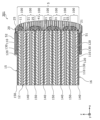
- FIG. 2 is a plan view of the power generation element 5 of the battery 1 according to the present embodiment, viewed from the side (positive side in the x-axis direction).
- FIG. 3 is another plan view of the power generation element 5 of the battery 1 according to the present embodiment, viewed from the side (positive side in the x-axis direction).
- FIG. 4A is a side view of battery 1 according to this embodiment.
- FIG. 4B is another side view of the battery 1 according to this embodiment.
- FIG. 1 represents a cross section taken along line II shown in FIG. 4A.
- FIGS. 2 and 3 show a state in which the battery 1 is in the middle of being manufactured.
- FIG. 1 represents a cross section taken along line II shown in FIG. 4A.
- FIGS. 2 and 3 show a state in which the battery 1 is in the middle of being manufactured.
- FIG. 1 represents a cross section taken along line II shown in FIG
- FIG. 2 is a diagram when the counter electrode insulating layer 31 and the electrode conductive extraction layer 41 are removed from the battery 1.
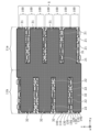
- FIG. 3 is a diagram when the electrode conductive extraction layer 41 is removed from the battery 1.
- the battery 1 is manufactured, for example, through the states shown in FIGS. 2 and 3 in this order.
- FIG. 4A is a plan view of the battery 1 when viewed from the positive side in the x-axis direction.
- FIG. 4B is a plan view of the battery 1 viewed from the negative side in the x-axis direction.
- the battery 1 includes a power generation element 5, a plurality of conductive pieces 20, a counter electrode insulating layer 31, an electrode insulating layer 32, an electrode conductive extraction layer 41, and a counter electrode conductive extraction layer 42. , an electrode current collecting terminal 51 and a counter electrode current collecting terminal 52.
- the battery 1 is, for example, an all-solid-state battery.
- the conductive piece 20 is an example of a conductive part.
- all the pieces with the dot pattern in the area surrounded by the rectangle of the two-dot chain line are the conductive pieces 20.
- the power generation element 5 has a structure in which a plurality of battery cells 100 and a plurality of current collectors are stacked along the thickness direction of the plurality of battery cells 100. Such a laminated structure allows the energy density of the battery 1 to be increased.
- the shape of the power generation element 5 in plan view is, for example, rectangular. That is, the general shape of the power generation element 5 is a flat rectangular parallelepiped.
- flatness means that the thickness (that is, the length in the z-axis direction) is shorter than each side of the main surface (that is, the length in each of the x-axis direction and the y-axis direction) or the maximum width.
- the shape of the power generation element 5 in plan view may be any other polygonal shape such as a square, hexagonal or octagonal shape, or may be circular or elliptical.
- the outer edge of the power generation element 5 in plan view may have unevenness.
- each layer is exaggerated in cross-sectional views such as FIG. 1 and side plan views such as FIGS. 2 to 4B in order to make the layered structure of the power generation element 5 easier to understand. It is illustrated as follows.
- the power generating element 5 includes a side surface and a main surface 15 and a main surface 16.
- the side surface of the power generating element 5 is a surface that connects the main surface 15 and the main surface 16.
- the general shape of the power generating element 5 is a rectangular parallelepiped, and the side surface of the power generating element 5 includes four side surfaces including the side surface 11 and the side surface 12 as individual surfaces.
- each of the four side surfaces of the power generating element 5, the main surface 15 and the main surface 16 are flat surfaces. This improves the mechanical strength of the end of the power generating element 5 without the entire or part of the battery cell 100 protruding from the end of the power generating element 5.
- the side surface 11 is an example of a first region of the side surface of the power generating element 5.
- the side surface 12 is an example of a second region of the side surface of the power generating element 5.
- the side surface of the power generating element 5 may be a curved surface or a combination of a flat surface and a curved surface.
- the side surfaces 11 and 12 are opposite each other and parallel to each other.
- the other two side surfaces of the power generation element 5 other than the side surface 11 and the side surface 12 are opposite to each other and parallel to each other. Further, the other two side surfaces are surfaces perpendicular to the side surface 11 and the side surface 12.
- the four side surfaces of the power generation element 5 are erected from each side of the main surface 15 and the main surface 16 perpendicularly to the main surface 15 and the main surface 16.
- Each of the four side surfaces of the power generation element 5 is, for example, a cut surface. Thereby, the area of each layer of the battery cell 100 is determined accurately by cutting, so that variations in the capacity of the battery 1 can be reduced and accuracy of battery capacity can be improved.
- the main surface 15 and the main surface 16 are opposite to each other and parallel to each other.
- the main surface 15 is the uppermost surface of the power generation element 5.
- the main surface 16 is the lowest surface of the power generation element 5.
- the main surface 15 and the main surface 16 each have a larger area than any of the four side surfaces of the power generation element 5, for example.
- the power generation element 5 includes a plurality of battery cells 100 and a plurality of current collectors.
- the plurality of current collectors include an electrode current collector 140 electrically connected to the electrode layer 110 and a counter electrode current collector 150 electrically connected to the counter electrode layer 120.
- each of the plurality of current collectors is either electrode current collector 140 or counter electrode current collector 150.
- the battery cell 100 is the minimum configuration of a power generation section of a battery, and is also referred to as a unit cell. Further, the battery cell 100 and the current collector stacked on the battery cell 100 may be collectively referred to as a unit cell.
- the plurality of battery cells 100 are stacked so as to be electrically connected in parallel.
- the plurality of battery cells 100 are stacked such that all the battery cells 100 included in the power generation element 5 are electrically connected in parallel.
- the number of battery cells 100 included in the power generation element 5 is seven, but the number is not limited to this.
- the number of battery cells 100 included in the power generation element 5 may be an even number such as 2 or 4, or an odd number such as 3 or 5.
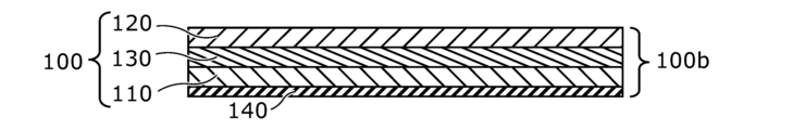
- Each of the multiple battery cells 100 includes an electrode layer 110, a counter electrode layer 120, and a solid electrolyte layer 130.
- the electrode layer 110 and the counter electrode layer 120 each include an active material, and are also referred to as an electrode active material layer and a counter electrode active material layer.
- the electrode layer 110, the solid electrolyte layer 130, and the counter electrode layer 120 are stacked in this order along the z-axis.
- the electrode layer 110 is one of the positive electrode layer and the negative electrode layer of the battery cell 100.
- the counter electrode layer 120 is the other of the positive electrode layer and the negative electrode layer of the battery cell 100.
- the case where the electrode layer 110 is a negative electrode layer and the counter electrode layer 120 is a positive electrode layer will be described as an example.
- Each of the plurality of battery cells 100 of the power generation element 5 includes two adjacent current collectors among the plurality of current collectors (specifically, one electrode current collector 140 and one counter electrode current collector 150). sandwiched between. Further, two adjacent battery cells 100 among the plurality of battery cells 100 are stacked via one of the plurality of current collectors.
- the configurations of the plurality of battery cells 100 are substantially the same.
- the order of the layers constituting the battery cells 100 is reversed.
- the plurality of battery cells 100 are stacked in a line along the z-axis, with the arrangement order of each layer constituting the battery cell 100 being alternated. Therefore, two adjacent battery cells 100 are arranged such that their electrode layers 110 or counter electrode layers 120 face each other.
- An electrode current collector 140 is arranged between the facing electrode layers 110, and a counter electrode current collector 150 is arranged between the facing counter electrode layers 120.
- an electrode current collector 140 is laminated on the electrode layer 110 without intervening the solid electrolyte layer 130, and a counter electrode current collector 150 is laminated on the counter electrode layer 120 without intervening the solid electrolyte layer 130.
- the electrode current collectors 140 and the counter electrode current collectors 150 are arranged alternately one by one along the z-axis direction.
- the battery 1 is a parallel-connected stacked battery in which a plurality of battery cells 100 and a plurality of current collectors are stacked and integrated.
- the lowest and highest parts of the power generating element 5 serve as layers and current collectors of different polarities, respectively.
- At least one of the lowermost portion and the uppermost portion of the power generation element 5 is composed of an electrode layer 110 and an electrode current collector 140, for example. Note that when the number of battery cells 100 is an even number, the lowermost part and the uppermost part of the power generating element 5 serve as a layer and a current collector of the same polarity, respectively.
- the plurality of current collectors includes a plurality of electrode current collectors 140 and a plurality of counter electrode current collectors 150. Note that when only two battery cells 100 are stacked, one of the electrode current collector 140 and the counter electrode current collector 150 becomes one, for example, the counter electrode current collector 150 becomes one.
- the plurality of electrode current collectors 140 and the plurality of counter electrode current collectors 150 are each exposed on the side surface of the power generation element 5 without being covered by the battery cell 100.
- the electrode current collectors 140 are not in direct contact with each other, and in order to connect the plurality of battery cells 100 in parallel, the plurality of electrode current collectors 140 are connected via the first electrode conductive piece 21 and the electrode conductive extraction layer 41. electrically connected.
- the counter electrode current collectors 150 are not in direct contact with each other, and in order to connect the plurality of battery cells 100 in parallel, the plurality of counter electrode current collectors 150 connect the second counter electrode conductive pieces 22 and the counter electrode conductive extraction layer 42. electrically connected via.
- the electrode current collector 140 and the counter electrode current collector 150 are each conductive foil-like, plate-like, or mesh-like members.
- the electrode current collector 140 and the counter electrode current collector 150 may each be, for example, a conductive thin film.
- the electrode current collector 140 and the counter electrode current collector 150 are each made of one metal foil.
- the electrode current collector 140 and the counter electrode current collector 150 may each have a multilayer structure of a plurality of current collecting layers made of a plurality of metal foils or the like. In this case, the plurality of current collecting layers are stacked directly or via an intermediate layer.
- Electrode current collector 140 and counter electrode current collector 150 may be formed using different materials.
- each of the electrode current collector 140 and the counter electrode current collector 150 is, for example, 5 ⁇ m or more and 200 ⁇ m or less, but is not limited thereto.
- the electrode layer 110 is in contact with the main surface of the electrode current collector 140.
- the electrode layer 110 is in contact with each of the two main surfaces.
- the electrode layer 110 is in contact with only one of the two main surfaces (specifically, the upper surface).
- the electrode current collector 140 may include a connection layer that is a layer containing a conductive material and provided in a portion that is in contact with the electrode layer 110.
- the counter electrode layer 120 is in contact with the main surface of the counter electrode current collector 150.
- the counter electrode layer 120 is in contact with each of the two main surfaces.
- the counter electrode layer 120 is in contact with only one of the two main surfaces (specifically, the lower surface).
- the counter electrode current collector 150 may include a connection layer that is a layer containing a conductive material and is provided in a portion in contact with the counter electrode layer 120.
- the electrode layer 110 is arranged on the main surface of the electrode current collector 140.
- the electrode layer 110 includes, for example, a negative electrode active material as an electrode material. Electrode layer 110 is placed opposite counter electrode layer 120 .
- the negative electrode active material contained in the electrode layer 110 may be, for example, graphite, metallic lithium, or other negative electrode active material.
- As the material for the negative electrode active material various materials capable of extracting and inserting ions such as lithium (Li) or magnesium (Mg) may be used.
- a solid electrolyte such as an inorganic solid electrolyte may be further used.
- an inorganic solid electrolyte for example, a sulfide solid electrolyte or an oxide solid electrolyte can be used.
- a sulfide solid electrolyte for example, a mixture of lithium sulfide (Li 2 S) and diphosphorus pentasulfide (P 2 S 5 ) can be used.
- a conductive agent such as acetylene black, a binding binder such as polyvinylidene fluoride, or the like may be further used.
- the electrode layer 110 is produced by applying a paste-like paint in which the material contained in the electrode layer 110 is kneaded together with a solvent, for example, onto the main surface of the electrode current collector 140 and drying it.
- the electrode current collector 140 also referred to as an electrode plate coated with the electrode layer 110 may be pressed after drying.
- the thickness of the electrode layer 110 is, for example, 5 ⁇ m or more and 300 ⁇ m or less, but is not limited thereto.
- the counter electrode layer 120 is arranged on the main surface of the counter electrode current collector 150.
- the counter electrode layer 120 is a layer containing a positive electrode material such as an active material.
- the positive electrode material is a material that constitutes the opposite electrode of the negative electrode material.
- the counter electrode layer 120 includes, for example, a positive electrode active material.
- Examples of the positive electrode active material contained in the counter electrode layer 120 include lithium cobaltate composite oxide (LCO), lithium nickelate composite oxide (LNO), lithium manganate composite oxide (LMO), lithium-manganese-nickel Positive electrode active materials such as composite oxide (LMNO), lithium-manganese-cobalt composite oxide (LMCO), lithium-nickel-cobalt composite oxide (LNCO), and lithium-nickel-manganese-cobalt composite oxide (LNMCO) can be used.
- As the material of the positive electrode active material various materials that can remove and insert ions such as Li or Mg can be used.
- a solid electrolyte such as an inorganic solid electrolyte may be further used.
- a sulfide solid electrolyte or an oxide solid electrolyte can be used.
- a mixture of Li 2 S and P 2 S 5 can be used.
- the surface of the positive electrode active material may be coated with a solid electrolyte.
- a conductive agent such as acetylene black, a binding binder such as polyvinylidene fluoride, etc. may further be used.
- the counter electrode layer 120 is produced by applying a paste-like paint in which the material contained in the counter electrode layer 120 is kneaded together with a solvent, for example, onto the main surface of the counter electrode current collector 150 and drying it.
- the counter electrode current collector 150 also referred to as a counter electrode plate coated with the counter electrode layer 120 may be pressed after drying.
- the thickness of the counter electrode layer 120 is, for example, 5 ⁇ m or more and 300 ⁇ m or less, but is not limited thereto.
- the solid electrolyte layer 130 is arranged between the electrode layer 110 and the counter electrode layer 120. Solid electrolyte layer 130 is in contact with each of electrode layer 110 and counter electrode layer 120.
- the solid electrolyte layer 130 has, for example, lithium ion conductivity.
- Solid electrolyte layer 130 is a layer containing an electrolyte material. As the electrolyte material, generally known electrolytes for batteries can be used.
- the thickness of the solid electrolyte layer 130 may be 5 ⁇ m or more and 300 ⁇ m or less, or 5 ⁇ m or more and 100 ⁇ m or less.
- the solid electrolyte layer 130 includes a solid electrolyte.
- a solid electrolyte such as an inorganic solid electrolyte can be used.
- an inorganic solid electrolyte a sulfide solid electrolyte or an oxide solid electrolyte can be used.
- a sulfide solid electrolyte for example, a mixture of Li 2 S and P 2 S 5 can be used.
- the solid electrolyte layer 130 may contain a binder such as polyvinylidene fluoride.
- the electrode layer 110, the counter electrode layer 120, and the solid electrolyte layer 130 are maintained in a parallel plate shape. Thereby, it is possible to suppress the occurrence of cracks or collapse due to curvature. Note that the electrode layer 110, the counter electrode layer 120, and the solid electrolyte layer 130 may be smoothly curved together.
- the electrode layer 110, the solid electrolyte layer 130, and the counter electrode layer 120 each have the same shape and size, and their respective contours match.
- the multiple battery cells 100 are substantially the same size as one another.
- the multiple battery cells 100, the multiple electrode current collectors 140, and the multiple counter electrode current collectors 150 each have the same shape and size, and their respective contours match.
- FIGS. 1 to 4B are plan views of the side surface 11 of the power generation element 5, respectively.
- FIG. 4B is a plan view of the side surface 12 of the power generation element 5 when viewed from above. Note that in FIGS. 2 to 4B, each configuration shown in the plan view is given the same shading as that of each configuration shown in the cross section of FIG. 1. This also applies to subsequent plan views.
- the battery 1 includes a plurality of discrete conductive pieces 20 provided on the side surfaces (specifically, the side surfaces 11 and 12) of the power generation element 5.
- the plurality of conductive pieces 20 are minute conductive members arranged on the side surface of the power generation element 5.
- Each of the plurality of conductive pieces 20 is, for example, in the form of a film or a plate whose thickness direction is perpendicular to the side surface of the power generation element 5 on which the conductive pieces 20 are arranged. Thereby, the connection area between the conductive piece 20 and the side surface of the power generation element 5 can be increased.
- the plurality of conductive pieces 20 may have a shape other than a film shape or a plate shape, such as a particle shape or a rod shape.
- the shape of the plurality of conductive pieces 20 is, for example, an ellipse, a rectangle, or a combination thereof. This makes it easy to form the conductive pieces 20.
- the plurality of conductive pieces 20 can be easily formed using a pattern mask or an inkjet method. Moreover, it is easy to increase the connection strength between the conductive pieces 20 and the current collector.
- the plurality of conductive pieces 20 have, for example, substantially the same shape and size, but may include conductive pieces 20 with different shapes and sizes. Note that the shape of the plurality of conductive pieces 20 in plan view is not particularly limited, and may be a shape other than the above, such as a polygon.
- the number of the plurality of conductive pieces 20 formed on the side surface 11 is greater than the number of battery cells 100 that the power generation element 5 has.
- the number of the plurality of conductive pieces 20 formed on the side surface 11 may be twice or more, three times or more, four times or more as the number of current collectors that the power generation element 5 has. It's okay.
- a connection with each conductive piece 20 is formed for each of the plurality of current collectors. , it becomes easier to secure the connection area between the conductive pieces 20 and the current collector.
- the upper limit of the number of the plurality of conductive pieces 20 formed on the side surface 11 may be set as appropriate depending on the size of the power generation element 5 and the conductive pieces 20, etc.
- the number of conductive pieces 20 is, for example, 1000 times or less the number of current collectors that the power generation element 5 has.
- the number of the plurality of conductive pieces 20 formed on the side surface 11 may be more than 1000 times the number of current collectors that the power generation element 5 has.
- the number of the plurality of conductive pieces 20 formed on the side surface 11 is 50 or less per 1 mm 2 .
- Each of the plurality of conductive pieces 20 includes, for example, only at least one of the electrode layer 110, the electrode current collector 140, the counter electrode layer 120, and the counter electrode current collector 150, or , contacts only at least one of the counter electrode layer 120 and the counter electrode current collector 150. That is, each of the plurality of conductive pieces 20 is not electrically connected to both the electrode layer 110 and the electrode current collector 140 and the counter electrode layer 120 and the counter electrode current collector 150.
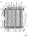
- the plurality of conductive pieces 20 are regularly arranged on the side surface 11.
- the plurality of conductive pieces 20 form, for example, rows or lattice points when viewed from the side surface 11 in plan. This makes it possible to design the arrangement of the plurality of conductive pieces 20 on the side surface 11 so that the conductive pieces 20 and the electrode current collector 140 are effectively connected.
- the plurality of conductive pieces 20 are arranged to form a plurality of rows along the stacking direction, for example, in a plan view of the side surface 11.
- the plurality of rows are arranged along a direction perpendicular to the stacking direction in a plan view of the side surface 11.
- the plurality of rows are arranged at equal intervals in a plan view of the side surface 11.
- the plurality of rows include rows in which the positional relationships of the conductive pieces 20 in the stacking direction are different from each other.
- the positional relationship of the conductive pieces 20 in the stacking direction has periodicity, and rows in which the positional relationship of the conductive pieces 20 in the stacking direction are the same are arranged in regular columns.
- the plurality of rows may have curved or bent portions such as a wavy line shape or a zigzag shape.
- the conductive pieces 20 are arranged at equal intervals.
- the number of conductive pieces 20 included in each of the plurality of columns is, for example, greater than the number of current collectors that the power generation element 5 has.
- the number of conductive pieces 20 included in each of the plurality of rows may be twice or more, or three times or more, the number of current collectors that the power generation element 5 has.
- the upper limit of the number of conductive pieces 20 included in each of the plurality of columns may be set appropriately depending on the size of the power generation element 5 and the conductive pieces 20, but the number of conductive pieces 20 included in each of the plurality of columns may be set appropriately.
- the number of conductive pieces 20 included is, for example, 10 times or less the number of current collectors that the power generation element 5 has.
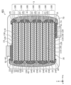
- the plurality of conductive pieces 20 are arranged, for example, in a plan view of the side surface 11 to form a plurality of inclined rows that are inclined with respect to the direction (y-axis direction) orthogonal to the stacking direction of the power generation elements 5.
- Ru In a plan view of the side surface 11, the direction perpendicular to the stacking direction of the power generation element 5 is also the direction in which each layer and each current collector of the power generation element 5 extend.
- the plurality of inclined rows have an inclination angle larger than the angle at which the diagonal line of the battery cell 100 is inclined with respect to a direction perpendicular to the direction in which the power generation elements 5 are stacked in the direction in which the power generation elements 5 are stacked.
- the plurality of inclined rows are formed by laminating the power generating elements 5 at an inclination angle smaller than the angle at which the diagonal line of the power generating elements is inclined with respect to a direction perpendicular to the laminating direction of the power generating elements 5 in a plan view of the side surface 11. Tilt with respect to the direction perpendicular to the direction.
- the plurality of inclined rows are arranged at equal intervals in a plan view of the side surface 11.
- the number of the plurality of inclined rows is greater than the number of current collectors that the power generation element 5 has.
- the number of the plurality of inclined rows may be twice or more, or three times or more, the number of current collectors that the power generation element 5 has. Further, the upper limit of the number of the plurality of inclined rows may be appropriately set according to the size of the power generation element 5 and the conductive pieces 20, etc., but the number of the plurality of inclined rows is, for example, The number of current collectors is 10 times or less. Further, in a plan view of the side surface 11, the conductive pieces 20 are arranged at equal intervals in each of the plurality of inclined rows.
- the plurality of conductive pieces 20 are arranged, for example, at positions corresponding to lattice points of a predetermined lattice when viewed from the side surface 11 in plan.
- the predetermined lattice include an orthorhombic lattice, a rhombic lattice, a centered rectangular lattice, an isosceles triangular lattice, a hexagonal lattice, an equilateral triangular lattice, a square lattice, a rectangular lattice, a primitive rectangular lattice, a parallel body lattice, and a distorted oblique lattice.
- the predetermined grid is not limited thereto.
- the plurality of conductive pieces 20 are also arranged on the side surface 12, for example, in the same layout as the side surface 11 described above.
- a plurality of conductive pieces 20 are arranged on the side surface 12 in the layout shown in FIG.
- the layout of the plurality of conductive pieces 20 is not limited to the example shown in FIG. 2, and can be designed as appropriate based on the contents explained above. Further, some of the plurality of conductive pieces 20 may be arranged regularly. Further, all of the plurality of conductive pieces 20 may be randomly arranged.
- the battery 1 may also have voids formed between adjacent conductive pieces 20.
- the voids are provided, for example, in place of any of the counter electrode insulating layer 31, the electrode conductive extraction layer 41, the electrode insulating layer 32, and the counter electrode conductive extraction layer 42 between adjacent conductive pieces 20.
- the voids are provided by not forming any of the counter electrode insulating layer 31, the electrode conductive extraction layer 41, the electrode insulating layer 32, and the counter electrode conductive extraction layer 42 between adjacent conductive pieces 20. This allows the voids to function as a buffer space against internal stress and mechanical shock due to expansion and contraction of the battery 1.
- the position at which the voids are formed is not limited to the above example, and may be formed anywhere on the outside of the side surface 11 and the outside of the side surface 12 of the power generating element 5 in the battery 1.
- the voids may be voids surrounded by an inner wall formed by at least one selected from the group consisting of the side surface 11, the multiple conductive pieces 20, the electrode conductive extraction layer 41, and the counter electrode insulating layer 31.
- the void may also be a void surrounded by an inner wall formed by at least one selected from the group consisting of the side surface 12, the plurality of conductive pieces 20, the counter electrode conductive extraction layer 42, and the electrode insulating layer 32.
- the plurality of conductive pieces 20 include a plurality of first electrode conductive pieces 21 and a plurality of first counter electrode conductive pieces 25.
- the first electrode conductive piece 21 is an example of a first electrode conductive part.
- the first counter electrode conductive piece 25 is an example of a first counter electrode conductive part.
- Each of the plurality of first electrode conductive pieces 21 is a conductive piece 20 connected to the electrode current collector 140 on the side surface 11. Further, the plurality of first electrode conductive pieces 21 are in contact with the electrode conductivity extraction layer 41 on the side surface 11 and are covered by the electrode conductivity extraction layer 41 . Note that the plurality of first electrode conductive pieces 21 may include first electrode conductive pieces 21 that are not covered with the electrode conductive extraction layer 41.
- Each of the plurality of first electrode conductive pieces 21 covers the electrode current collector 140 on the side surface 11. Further, the plurality of first electrode conductive pieces 21 are connected to each of the plurality of electrode current collectors 140 of the power generation element 5 in contact with each other on the side surface 11, and cover each of the plurality of electrode current collectors 140. . Each of the plurality of first electrode conductive pieces 21 is connected to any one of the plurality of electrode current collectors 140. Further, each of the plurality of electrode current collectors 140 is connected to at least one first electrode conductive piece 21. Each first electrode conductive piece 21 is not connected to two or more electrode current collectors 140 on the side surface 11 .
- Each of the plurality of first electrode conductive pieces 21 overlaps with one of the plurality of electrode current collectors 140 in a plan view of the side surface 11. Further, each of the plurality of first electrode conductive pieces 21 is connected to and contacts the electrode layer 110 on the side surface 11, and covers the electrode layer 110. Each of the plurality of first electrode conductive pieces 21 is not in contact with each of the plurality of counter electrode current collectors 150 of the power generation element 5 and the counter electrode layer 120 of each of the plurality of battery cells 100. Further, the plurality of first electrode conductive pieces 21 may include a first electrode conductive piece 21 that contacts the solid electrolyte layer 130 and covers the solid electrolyte layer 130 on the side surface 11 . Further, the plurality of first electrode conductive pieces 21 may include a first electrode conductive piece 21 that is not in contact with the electrode layer 110 on the side surface 11.
- the plurality of first electrode conductive pieces 21 include two or more first electrode conductive pieces 21 connected to the same electrode current collector 140 on the side surface 11. Thereby, the connection area between the electrode current collector 140 and the first electrode conductive piece 21 can be further increased.
- the electrical connection structure with the electrode current collector 140 on the side surface 11 becomes strong.
- the electrode conductive extraction layer 41 is connected via the first electrode conductive piece 21 rather than being directly connected to each of the plurality of electrode current collectors 140 on the side surface 11. 21 and the electrode current collector 140 can be easily brought into contact with each other, and the connection strength can be increased.
- the plurality of conductive pieces 20 are formed discretely on the side surface 11, the internal stress of the first electrode conductive pieces 21 can be dispersed and relaxed. Further, even if the first electrode conductive pieces 21 thermally expand due to temperature rise during charging and discharging with a large current, embrittlement and peeling of the first electrode conductive pieces 21 can be suppressed.
- Each of the plurality of first counter electrode conductive pieces 25 is a conductive piece 20 connected to the counter electrode current collector 150 on the side surface 11. Further, the plurality of first counter electrode conductive pieces 25 are in contact with the counter electrode insulating layer 31 on the side surface 11 and are covered by the counter electrode insulating layer 31 . Note that the plurality of first counter electrode conductive pieces 25 may include first counter electrode conductive pieces 25 that are not covered with the counter electrode insulating layer 31.
- Each of the plurality of first counter electrode conductive pieces 25 covers the counter electrode current collector 150 on the side surface 11. Further, the plurality of first counter electrode conductive pieces 25 are connected in contact with each of the plurality of counter electrode current collectors 150 of the power generation element 5 on the side surface 11, and cover each of the plurality of counter electrode current collectors 150. . Each of the plurality of first counter electrode conductive pieces 25 is connected to any one of the plurality of counter electrode current collectors 150. Furthermore, each of the plurality of counter electrode current collectors 150 is connected to at least one first counter electrode conductive piece 25 . Each first counter electrode conductive piece 25 is not connected to two or more counter electrode current collectors 150 on the side surface 11 . Each of the plurality of first counter electrode conductive pieces 25 is not in contact with each of the plurality of electrode current collectors 140 of the power generation element 5 and the electrode layer 110 of each of the plurality of battery cells 100.
- the plurality of conductive pieces 20 include the first counter electrode conductive pieces 25 connected to the counter electrode current collector 150 at the side surface 11 by being formed without alignment, etc. Since the conductive pieces 25 are covered with the counter electrode insulating layer 31, short circuits via the first counter electrode conductive pieces 25 are suppressed. Therefore, both high productivity and high reliability of the battery 1 can be achieved.
- the plurality of conductive pieces 20 include a plurality of second counter electrode conductive pieces 22 and a plurality of second electrode conductive pieces 26.
- the second counter electrode conductive piece 22 is an example of a second counter electrode conductive part.
- the second electrode conductive piece 26 is an example of a second electrode conductive part.
- Each of the plurality of second counter electrode conductive pieces 22 is a conductive piece 20 connected to a different counter electrode current collector 150 on the side surface 12. Further, the plurality of second counter electrode conductive pieces 22 are in contact with the counter electrode conductive extraction layer 42 on the side surface 12 and are covered by the counter electrode conductive extraction layer 42 . Note that the plurality of second counter electrode conductive pieces 22 may include second counter electrode conductive pieces 22 that are not covered with the counter electrode conductive extraction layer 42.
- Each of the plurality of second counter electrode conductive pieces 22 covers the counter electrode current collector 150 on the side surface 12. Further, the plurality of second counter electrode conductive pieces 22 are connected in contact with each of the plurality of counter electrode current collectors 150 of the power generation element 5 on the side surface 12, and cover each of the plurality of counter electrode current collectors 150. . Each of the plurality of second counter electrode conductive pieces 22 is connected to any one of the plurality of counter electrode current collectors 150. Furthermore, each of the plurality of counter electrode current collectors 150 is connected to at least one second counter electrode conductive piece 22 . Each second counter electrode conductive piece 22 is not connected to two or more counter electrode current collectors 150 on the side surface 12 .
- Each of the plurality of second counter electrode conductive pieces 22 overlaps with one of the plurality of counter electrode current collectors 150 in a plan view of the side surface 12. Further, each of the plurality of second counter electrode conductive pieces 22 is connected to and contacts the counter electrode layer 120 on the side surface 12, and covers the counter electrode layer 120. Each of the plurality of second counter electrode conductive pieces 22 is not in contact with each of the plurality of electrode current collectors 140 of the power generation element 5 and the electrode layer 110 of each of the plurality of battery cells 100. Further, the plurality of second counter electrode conductive pieces 22 may include a second counter electrode conductive piece 22 that contacts the solid electrolyte layer 130 and covers the solid electrolyte layer 130 on the side surface 12. Further, the plurality of second counter electrode conductive pieces 22 may include second counter electrode conductive pieces 22 that are not in contact with the counter electrode layer 120 on the side surface 12 .
- the plurality of second counter electrode conductive pieces 22 include two or more second counter electrode conductive pieces 22 connected to the same counter electrode current collector 150 on the side surface 12. Thereby, the connection area between the counter electrode current collector 150 and the second counter electrode conductive pieces 22 can be further increased.
- the second counter electrode conductive piece 22 is connected to the counter electrode collector 150 on the side surface 12, so that the electrical connection structure with the counter electrode collector 150 on the side surface 12 is strong.
- the connection strength can be increased.
- the multiple conductive pieces 20 are formed discretely on the side surface 12, the internal stress of the second counter electrode conductive piece 22 can be dispersed and relaxed.
- embrittlement and peeling of the second counter electrode conductive piece 22 can be suppressed.
- Each of the plurality of second electrode conductive pieces 26 is a conductive piece 20 connected to the electrode current collector 140 on the side surface 12. Furthermore, the plurality of second electrode conductive pieces 26 are in contact with the electrode insulating layer 32 on the side surface 12 and are covered by the electrode insulating layer 32 . Note that the plurality of second electrode conductive pieces 26 may include second electrode conductive pieces 26 that are not covered with the electrode insulating layer 32.
- Each of the plurality of second electrode conductive pieces 26 covers the electrode current collector 140 on the side surface 12. Further, the plurality of second electrode conductive pieces 26 are connected to each of the plurality of electrode current collectors 140 of the power generation element 5 in contact with each other on the side surface 12, and cover each of the plurality of electrode current collectors 140. . Each of the plurality of second electrode conductive pieces 26 is connected to any one of the plurality of electrode current collectors 140. Further, each of the plurality of electrode current collectors 140 is connected to at least one second electrode conductive piece 26. Each second electrode conductive piece 26 is not connected to two or more electrode current collectors 140 on the side surface 12 . Each of the plurality of second electrode conductive pieces 26 is not in contact with each of the plurality of counter electrode current collectors 150 of the power generation element 5 and the counter electrode layer 120 of each of the plurality of battery cells 100.
- the plurality of conductive pieces 20 include the second electrode conductive pieces 26 connected to the electrode current collector 140 at the side surface 12, such as by being formed without alignment; Since the conductive pieces 26 are covered with the electrode insulating layer 32, short circuits via the second electrode conductive pieces 26 are suppressed. Therefore, both high productivity and high reliability of the battery 1 can be achieved.
- the plurality of conductive pieces 20 are formed using a conductive resin material or the like.
- the conductive resin material includes, for example, a resin and a conductive material filled in the resin and made of metal particles or the like.
- the plurality of conductive pieces 20 may be formed using a metal material such as solder.
- the conductive materials that can be used are selected based on various properties such as flexibility, gas barrier properties, impact resistance, and heat resistance.
- the battery 1 includes the plurality of discrete conductive pieces 20 provided on the side surface of the power generation element 5, so that the electrodes are collected on the side surface of the power generation element 5 by the plurality of discrete conductive pieces 20.
- Positioning for connecting the plurality of conductive pieces 20 to the electric body 140 and the counter electrode current collector 150 can be eliminated or simplified. That is, in the battery 1, even if alignment is eliminated or simplified in forming the plurality of conductive pieces 20, the first electrode conductive pieces 21 connected to the electrode current collector 140 and the counter electrode current collector 150 are not connected to each other.
- a second counter electrode conductive piece 22 can be formed.
- the battery 1 since the battery 1 includes a plurality of discrete conductive pieces 20, the connection between the conductive pieces 20 and the current collector is easily maintained on the side surface of the power generation element 5. Specifically, even if alignment in forming the plurality of conductive pieces 20 is eliminated or simplified, connection with the current collector can be formed by any one of the plurality of conductive pieces 20. Therefore, connection failures in the connection structure with the current collector on the side surface of the power generation element 5 can be reduced, and an increase in connection resistance can be suppressed. Thereby, voltage loss caused by connection resistance on the side surface of the power generation element 5 can be suppressed even during charging and discharging of a large current.
- connection structure with the current collector on the side surface of the power generation element 5 can be suppressed, and strength deterioration of the connection structure due to thermal expansion and deformation can be suppressed.
- FIGS. 5A and 5B are diagrams for explaining the size of the conductive piece 20.
- (a) of FIG. 5A and FIG. 5B shows a plan view of one battery cell 100 provided in the power generating element 5, and one electrode collector 140 and one counter electrode collector 150 stacked on the battery cell 100, as viewed from the positive side in the x-axis direction.
- (b) of FIG. 5A and FIG. 5B shows a plan view of the conductive piece 20 as viewed from the positive side in the x-axis direction. Therefore, in the plan view of the side surface 11, FIGS. 5A and 5B show the shape of one battery cell 100, one electrode collector 140 and one counter electrode collector 150 stacked on the battery cell 100, and the shape of the conductive piece 20.
- the length Lz of the conductive piece 20 in the stacking direction (z-axis direction) of the power generation element 5 is, for example, the thickness of each layer of the electrode layer 110, solid electrolyte layer 130, and counter electrode layer 120. less than the sum of In the present embodiment, the total thickness of each of the electrode layer 110, solid electrolyte layer 130, and counter electrode layer 120 is the length La of the battery cell 100 in the stacking direction of the power generation elements 5. Thereby, short circuits caused by the conductive pieces 20 can be suppressed. In the example shown in FIG.
- the length Lz of the conductive pieces 20 in plan view may be larger than the thickness of the solid electrolyte layer 130, but the length Lz of the conductive pieces 20 in the stacking direction of the power generation element 5 is The length of the portion in contact with the side surface of the power generation element 5 is smaller than the thickness of the solid electrolyte layer 130.
- the length Lz of the conductive piece 20 in the stacking direction (z-axis direction) of the power generation element 5 is smaller than the thickness Lb of the solid electrolyte layer 130, for example. Thereby, short circuits caused by the conductive pieces 20 can be further suppressed.
- the length Lz of the conductive piece 20 in the stacking direction (z-axis direction) of the power generating element 5 is, for example, greater than both the thickness Lc of the electrode collector 140 and the thickness of the counter electrode collector 150. This increases the connection area between the conductive piece 20 and the electrode collector 140 or the counter electrode collector 150, thereby reducing the connection resistance between the conductive piece 20 and the electrode collector 140 or the counter electrode collector 150. In the example shown in FIG.
- the thickness Lc of the electrode collector 140 and the thickness of the counter electrode collector 150 are the same, but when the thickness Lc of the electrode collector 140 and the thickness of the counter electrode collector 150 are different, the length Lz of the conductive piece 20 in the stacking direction (z-axis direction) of the power generating element 5 may be greater than the thickness of at least one of the electrode collector 140 and the counter electrode collector 150.
- the length Lz of the conductive pieces 20 in the stacking direction (z-axis direction) of the power-generating elements 5 is, for example, direction) is smaller than the length Ly of the conductive piece 20.
- the plurality of conductive pieces 20 each have the above-mentioned size, for example, but may also include conductive pieces 20 of different sizes.
- the battery 1 includes a plurality of counter electrode insulating layers 31 and a plurality of electrode insulating layers 32. Note that the plurality of counter electrode insulating layers 31 may be connected to each other to form one or more counter electrode insulating layers 31. Furthermore, the plurality of electrode insulating layers 32 may be connected to each other to form one or more electrode insulating layers 32.
- each of the plurality of counter electrode insulating layers 31 covers at least a portion of a different counter electrode current collector 150 on the side surface 11.
- Each of the plurality of counter electrode insulating layers 31 has an elongated shape extending in a direction perpendicular to the stacking direction of the power generation elements 5 when viewed from the side surface 11 in plan.
- the plurality of counter electrode insulating layers 31 are in contact with the plurality of first counter electrode conductive pieces 25 on the side surface 11 and cover the plurality of first counter electrode conductive pieces 25 .
- the counter electrode insulating layer 31 overlaps with the whole of one or more first counter electrode conductive pieces 25 in a plan view of the side surface 11 . Further, the plurality of counter electrode insulating layers 31 do not cover at least a portion of the plurality of first electrode conductive pieces 21 on the side surface 11 . Note that the plurality of counter electrode insulating layers 31 may cover a part of the plurality of first electrode conductive pieces 21 on the side surface 11.
- each of the plurality of counter electrode insulating layers 31 is located between the side surface 11 and the electrode conductive extraction layer 41. In this manner, by providing the battery 1 with a plurality of counter electrode insulating layers 31, short circuits due to contact between the counter electrode current collector 150 or the first counter electrode conductive pieces 25 and the electrode conductive extraction layer 41 can be suppressed.
- each of the plurality of counter electrode insulating layers 31 contacts each of the plurality of counter electrode current collectors 150 of the power generation element 5 on the side surface 11, and It covers each of the bodies 150.
- one counter electrode insulating layer 31 covers one counter electrode current collector 150.
- Each of the plurality of counter electrode insulating layers 31 overlaps each of the plurality of counter electrode current collectors 150 and extends along each of the plurality of counter electrode current collectors 150 in a plan view of the side surface 11 .
- the plurality of counter electrode insulating layers 31 are in contact with and cover the counter electrode layer 120 of each of the plurality of battery cells 100 on the side surface 11 .
- the counter electrode insulating layer 31 does not cover each of the plurality of electrode current collectors 140 of the power generation element 5 and the electrode layer 110 of each of the plurality of battery cells 100. Therefore, the plurality of counter electrode insulating layers 31 have a stripe shape when viewed from the side surface 11 in plan. Further, the plurality of counter electrode insulating layers 31 are arranged along the stacking direction of the power generation elements 5 when viewed from the side surface 11 in plan.
- the counter electrode insulating layer 31 continuously covers the counter electrode layer 120 and the solid electrolyte layer 130 of the two adjacent battery cells 100. Specifically, the counter electrode insulating layer 31 is continuous from at least a portion of one electrode layer 110 of two adjacent battery cells 100 to at least a portion of the other electrode layer 110 of the two adjacent battery cells 100. covered.
- the counter electrode insulating layer 31 covers at least a portion of the solid electrolyte layer 130 on the side surface 11.
- the width (length in the z-axis direction) of the counter electrode insulating layer 31 changes due to manufacturing variations, the risk of exposing the counter electrode layer 120 is reduced. Therefore, short-circuiting between the electrode layer 110 and the counter electrode layer 120 via the electrode conductive extraction layer 41 formed to cover the counter electrode insulating layer 31 can be suppressed.
- the end face of the solid electrolyte layer 130 formed of a powder material has very fine irregularities. Therefore, since the counter electrode insulating layer 31 enters into the irregularities, the adhesion strength of the counter electrode insulating layer 31 is improved, and insulation reliability is improved.
- the outline of the counter electrode insulating layer 31 overlaps the electrode layer 110 on the side surface 11. Note that it is not essential that the counter electrode insulating layer 31 cover the electrode layer 110 and the solid electrolyte layer 130 on the side surface 11. For example, on the side surface 11, the outline of the counter electrode insulating layer 31 may overlap the boundary between the solid electrolyte layer 130 and the counter electrode layer 120. Further, on the side surface 11, the outline of the counter electrode insulating layer 31 may overlap the solid electrolyte layer 130.
- the counter electrode insulating layer 31 is provided separately for each counter electrode current collector 150, but the present invention is not limited thereto.
- the counter electrode insulating layer 31 may be provided along the z-axis direction at the end of the side surface 11 in the y-axis direction, in addition to the striped portion. That is, the counter electrode insulating layer 31 may have a ladder shape or a lattice shape when viewed from the side surface 11 in plan. In this way, the counter electrode insulating layer 31 may cover a part of the electrode current collector 140.
- the uppermost layer is the counter electrode current collector 150.
- the counter electrode insulating layer 31 covers a part of the main surface (that is, the main surface 15) of the counter electrode current collector 150 where the uppermost layer is located.
- the counter electrode insulating layer 31 is strong against external forces from the z-axis direction, and detachment is suppressed.
- the electrode conductive extraction layer 41 wraps around the main surface 15 of the power generation element 5, it is possible to prevent the electrode conductive extraction layer 41 from coming into contact with the counter electrode current collector 150 and causing a short circuit.
- the length of each of the plurality of counter electrode insulating layers 31 in the direction (y-axis direction) perpendicular to the stacking direction of the power generating element 5 is the length of the electrode conductive extraction layer 41. longer than length. Thereby, the reliability of the battery 1 can be further improved.
- the electrode conductivity extraction layer 41 is located inside both ends of each of the plurality of counter electrode insulating layers 31 in the y-axis direction.
- the length of the counter electrode insulating layer 31 in the direction (y-axis direction) perpendicular to the stacking direction of the power generation element 5 may be shorter than the length of the power generation element 5 in the y-axis direction.
- the length may be the same as the length of the power generation element 5 in the axial direction, or may be longer than the length of the power generation element 5 in the y-axis direction.
- the plurality of counter electrode insulating layers 31 have the same length in the y-axis direction, but may include counter electrode insulating layers 31 having different lengths in the y-axis direction.
- each of the plurality of electrode insulating layers 32 covers at least a portion of a different electrode current collector 140 on the side surface 12.
- Each of the plurality of electrode insulating layers 32 has an elongated shape extending in a direction perpendicular to the stacking direction of the power generation elements 5 in a plan view of the side surface 12.
- the plurality of electrode insulating layers 32 are in contact with the plurality of second electrode conductive pieces 26 on the side surface 12, and cover the plurality of second electrode conductive pieces 26.
- the electrode insulating layer 32 overlaps with the entire one or more second electrode conductive pieces 26 when viewed from the side surface 12 in plan.
- the plurality of electrode insulating layers 32 do not cover at least a portion of the plurality of second counter electrode conductive pieces 22 on the side surface 12 .
- the plurality of electrode insulating layers 32 may partially cover the plurality of second counter electrode conductive pieces 22 on the side surface 12.
- each of the plurality of electrode insulating layers 32 is located between the side surface 12 and the counter electrode conductive extraction layer 42. In this way, by providing the battery 1 with a plurality of electrode insulating layers 32, short circuits due to contact between the electrode current collector 140 or the second electrode conductive piece 26 and the counter electrode conductive extraction layer 42 can be suppressed.
- each of the plurality of electrode insulating layers 32 contacts each of the plurality of electrode current collectors 140 of the power generation element 5 on the side surface 12, and covering each.
- one electrode insulating layer 32 covers one electrode current collector 140.
- Each of the plurality of electrode insulating layers 32 overlaps each of the plurality of electrode current collectors 140 in a plan view of the side surface 12, and extends along each of the plurality of electrode current collectors 140. Further, the plurality of electrode insulating layers 32 are in contact with and cover the electrode layer 110 of each of the plurality of battery cells 100 on the side surface 12 .
- the electrode insulating layer 32 does not cover each of the plurality of counter electrode current collectors 150 of the power generation element 5 and the counter electrode layer 120 of each of the plurality of battery cells 100. Therefore, the plurality of electrode insulating layers 32 have a stripe shape when viewed from the side surface 12 in plan. Further, the plurality of electrode insulating layers 32 are arranged along the stacking direction of the power generation element 5 in a plan view of the side surface 12.
- the electrode insulating layer 32 continuously covers the electrode layer 110 and solid electrolyte layer 130 of the two adjacent battery cells 100. Specifically, the electrode insulating layer 32 is continuous from at least a portion of one counter electrode layer 120 of two adjacent battery cells 100 to at least a portion of the other counter electrode layer 120 of the two adjacent battery cells 100. covered.
- the electrode insulating layer 32 covers at least a portion of the solid electrolyte layer 130 on the side surface 12. This reduces the risk of exposing the electrode layer 110 even if the width (length in the z-axis direction) of the electrode insulating layer 32 varies due to manufacturing variations. This makes it possible to prevent the electrode layer 110 and the counter electrode layer 120 from shorting out through the counter electrode conductive extraction layer 42 formed to cover the electrode insulating layer 32.
- the end surface of the solid electrolyte layer 130 formed of a powder-like material has very fine irregularities. Therefore, the electrode insulating layer 32 penetrates into the irregularities, improving the adhesion strength of the electrode insulating layer 32 and improving insulation reliability.
- the outline of the electrode insulating layer 32 overlaps the counter electrode layer 120 on the side surface 12. Note that it is not essential that the electrode insulating layer 32 cover the counter electrode layer 120 and the solid electrolyte layer 130 on the side surface 12. For example, on the side surface 12, the outline of the electrode insulating layer 32 may overlap the boundary between the solid electrolyte layer 130 and the electrode layer 110. Further, on the side surface 12, the outline of the electrode insulating layer 32 may overlap the solid electrolyte layer 130.
- the electrode insulating layer 32 is provided separately for each electrode current collector 140, but this is not limited thereto.
- the electrode insulating layer 32 may be provided along the z-axis direction at the end of the side surface 12 in the y-axis direction, in addition to the stripe-shaped portion.
- the electrode insulating layer 32 may have a ladder shape or a lattice shape in a plan view of the side surface 12. In this way, the electrode insulating layer 32 may cover a portion of the counter electrode current collector 150.
- the electrode current collector 140 is the lowest layer. As shown in FIG. 1, in the vicinity of the lower end of the side surface 12, the electrode insulating layer 32 covers a part of the main surface (that is, the main surface 16) of the electrode current collector 140 located at the bottom layer. As a result, the electrode insulating layer 32 is strong against external forces from the z-axis direction, and detachment is suppressed. Further, even when the counter electrode conductive extraction layer 42 wraps around the main surface 16 of the power generation element 5, it is possible to prevent the counter electrode conductive extraction layer 42 from coming into contact with the electrode current collector 140 and causing a short circuit.
- the length of each of the plurality of electrode insulating layers 32 in the direction (y-axis direction) perpendicular to the stacking direction of the power generation element 5 is equal to the length of the counter electrode conductive extraction layer 42. longer than length. Thereby, the reliability of the battery 1 can be further improved. Further, the counter electrode conductive extraction layer 42 is located inside both ends of each of the plurality of electrode insulating layers 32 in the y-axis direction.
- the length of the electrode insulating layer 32 in the direction (y-axis direction) perpendicular to the stacking direction of the power generation element 5 may be shorter than the length of the power generation element 5 in the y-axis direction.
- the length may be the same as the length of the power generation element 5 in the axial direction, or may be longer than the length of the power generation element 5 in the y-axis direction.
- the plurality of electrode insulating layers 32 have the same length in the y-axis direction, but may include electrode insulating layers 32 having different lengths in the y-axis direction.
- the counter electrode insulating layer 31 and the electrode insulating layer 32 are each formed using an electrically insulating material.
- the counter electrode insulating layer 31 and the electrode insulating layer 32 each contain resin. Thereby, the impact resistance of the battery 1 can be improved, and the stress applied to the battery 1 due to temperature changes of the battery 1 and expansion and contraction during charging and discharging can be alleviated.
- the resin is, for example, an epoxy resin, but is not limited thereto.
- an inorganic material may be used as the insulating material. Insulating materials that can be used are selected based on various properties such as flexibility, gas barrier properties, impact resistance, and heat resistance.
- the counter electrode insulating layer 31 and the electrode insulating layer 32 are formed using the same material, but may be formed using different materials.
- the electrode conductive extraction layer 41 covers the plurality of first electrode conductive pieces 21 and the plurality of counter electrode insulating layers 31 on the side surface 11, and covers the plurality of first electrode conductive pieces 21 and the plurality of counter electrode insulating layers 31. are electrically connected to each.
- the electrode conductive extraction layer 41 is a conductive concentration part that electrically connects the plurality of first electrode conductive pieces 21 together.
- the electrode conductive extraction layer 41 is in contact with the plurality of first electrode conductive pieces 21 .
- the electrode conductive extraction layer 41 does not overlap with a part of the counter electrode insulating layer 31 in a plan view of the side surface 11. Note that the electrode conductivity extraction layer 41 may overlap the entire counter electrode insulating layer 31 in a plan view of the side surface 11.
- the electrode conductive extraction layer 41 is electrically connected to each of the plurality of electrode current collectors 140 and the electrode layer 110 of each of the plurality of battery cells 100 via the plurality of first electrode conductive pieces 21. There is. That is, the electrode conductive extraction layer 41 has a function of electrically connecting each battery cell 100 in parallel.
- the electrode conductive extraction layer 41 can extract the current from the electrode layer 110 of the entire battery 1 . As shown in FIGS. 1 and 4A, the electrode conductive extraction layer 41 covers almost the entire side surface 11 from the lower end to the upper end. Further, a portion of the electrode conductive extraction layer 41 is in direct contact with each of the plurality of electrode current collectors 140 and the electrode layer 110 of each of the plurality of battery cells 100.
- the electrode conductive extraction layer 41 may be provided from the side surface 11 of the power generation element 5 to another side surface adjacent to the side surface 11, and the first electrode conductive piece 21 may also be provided on the other side surface.
- the electrode conductive extraction layer 41 is connected to the electrode current collector 140 connected to the first electrode conductive piece 21 on the other side surface via the first electrode conductive piece 21 on the side surface 11. It does not need to be electrically connected.
- the battery 1 is provided with the electrode conductive extraction layer 41 that covers at least a portion of the counter electrode insulating layer 31 and is electrically connected to the first electrode conductive pieces 21 on the side surface 11.
- a lead-out electrode for the electrode layer 110 can be easily realized.
- the electrode conductive extraction layer 41 and the plurality of first counter electrode conductive pieces 25 overlap in plan view of the side surface 11 and face each other with the counter electrode insulating layer 31 in between. Thereby, even when the plurality of first counter electrode conductive pieces 25 are provided on the side surface 11, short circuits due to contact between the plurality of first counter electrode conductive pieces 25 and the electrode conductive extraction layer 41 can be suppressed.
- the counter electrode conductive extraction layer 42 covers the plurality of second counter electrode conductive pieces 22 and the plurality of electrode insulating layers 32 on the side surface 12, and covers the plurality of second counter electrode conductive pieces 22. are electrically connected to each.
- the counter electrode conductive extraction layer 42 is a conductive collecting portion that electrically connects the plurality of second counter electrode conductive pieces 22 together.
- the counter electrode conductive extraction layer 42 is in contact with the plurality of second counter electrode conductive pieces 22 .
- the counter electrode conductive extraction layer 42 does not overlap with a part of the electrode insulating layer 32 in a plan view of the side surface 12 .
- the counter electrode conductive extraction layer 42 may overlap the entire electrode insulating layer 32 in a plan view of the side surface 12.
- the counter electrode conductive extraction layer 42 is electrically connected to each of the plurality of counter electrode current collectors 150 and the counter electrode layer 120 of each of the plurality of battery cells 100 via the plurality of second counter electrode conductive pieces 22. There is. That is, the counter electrode conductive extraction layer 42 has a function of electrically connecting each battery cell 100 in parallel.
- the counter electrode conductive extraction layer 42 can extract the current from the counter electrode layer 120 of the entire battery 1 . As shown in FIGS. 1 and 4B, the counter electrode conductive extraction layer 42 covers almost the entire side surface 12 from the lower end to the upper end. Further, a portion of the counter electrode conductive extraction layer 42 is in direct contact with each of the plurality of counter electrode current collectors 150 and the counter electrode layer 120 of each of the plurality of battery cells 100.
- the counter electrode current collector 150 and a counter electrode layer 120 may be provided from the side surface 12 of the power generation element 5 to another side surface adjacent to the side surface 12, and the second counter electrode conductive piece 22 may also be provided on the other side surface.
- the counter electrode conductive extraction layer 42 is connected to the counter electrode current collector 150 connected to the second counter electrode conductive piece 22 on the other side surface through the second counter electrode conductive piece 22 on the side surface 12. It does not need to be electrically connected.
- the battery 1 is provided with a counter electrode conductive extraction layer 42 on the side surface 12 that covers at least a portion of the electrode insulating layer 32 and is electrically connected to the second counter electrode conductive piece 22, making it easy to realize an extraction electrode for the counter electrode layer 120 of the battery 1.
- the electrode conductive extraction layer 41 and the counter electrode conductive extraction layer 42 are each formed using a conductive resin material or the like.
- the conductive resin material includes, for example, a resin and a conductive material filled in the resin and made of metal particles or the like.
- the electrode conductive extraction layer 41 and the counter electrode conductive extraction layer 42 may each be formed using a metal material such as solder.
- the conductive materials that can be used are selected based on various properties such as flexibility, gas barrier properties, impact resistance, and heat resistance.
- the electrode conductive extraction layer 41 and the counter electrode conductive extraction layer 42 are formed using the same material, but may be formed using different materials.
- the electrode conductive extraction layer 41 and the counter electrode conductive extraction layer 42 may be formed using the same material as the plurality of conductive pieces 20, or may be formed using different materials.
- the electrode conductivity extraction layer 41 and the counter electrode conductivity extraction layer 42 may be used using a material different from that of the plurality of conductive pieces 20, it is appropriate to use a material that differs in at least one of hardness, adhesiveness, electrical conductivity, and corrosion resistance, for example. By being used in combination with, battery characteristics or durability can be improved.
- the electrode conductive extraction layer 41 and the counter electrode conductive extraction layer 42 may be harder than the plurality of conductive pieces 20.
- the electrode current collecting terminal 51 is a conductive terminal electrically connected to the electrode conductive extraction layer 41.
- the electrode current collector terminal 51 is one of the external connection terminals of the battery 1, and in this embodiment, is a negative electrode extraction terminal.
- the electrode current collector terminal 51 is arranged on the main surface 16 of the power generation element 5. That is, the electrode current collector terminal 51 is provided on the main surface 16. Note that "the terminal is provided on the main surface” means not only the case where the terminal is arranged directly on the main surface but also the case where the terminal is arranged on the main surface with another layer interposed therebetween.
- the electrode current collector terminal 51 is arranged on the main surface 16 away from the side surface 11. That is, the electrode conductivity extraction layer 41 is provided so as to cover the area between the side surface 11 and the electrode current collector terminal 51 on the main surface 16 .
- the electrode conductive extraction layer 41 continuously covers from the side surface 11 to the main surface 16 and is connected to the electrode current collecting terminal 51 by contacting it.
- the electrode current collector terminal 51 has higher conductivity than the electrode current collector 140, for example.
- the thickness (length in the z-axis direction) of the electrode current collector terminal 51 is thicker than the thickness of the electrode current collector 140, for example. Thereby, the conductivity of the electrode current collecting terminal 51 can be increased and the resistance of the lead-out electrode structure can be reduced.
- the counter electrode current collector terminal 52 is a conductive terminal electrically connected to the counter electrode conductive extraction layer 42.
- the counter electrode current collector terminal 52 is one of the external connection terminals of the battery 1, and in this embodiment, is a positive electrode extraction terminal.
- the counter current collector terminal 52 is arranged on the main surface 15 of the power generation element 5. That is, the counter current collector terminal 52 is provided on the main surface 15.
- the counter electrode current collecting terminal 52 is disposed on the main surface 15 away from the side surface 12.
- the counter electrode conductive extraction layer 42 is provided so as to cover the area of the main surface 15 between the side surface 12 and the counter electrode current collecting terminal 52.
- the counter electrode conductive extraction layer 42 continuously covers the area from the side surface 12 to the main surface 15, and is in contact with and connected to the counter electrode current collecting terminal 52.
- the counter electrode current collector terminal 52 has a higher conductivity than, for example, the counter electrode current collector 150.
- the thickness (length in the z-axis direction) of the counter electrode current collector terminal 52 is, for example, thicker than the thickness of the counter electrode current collector 150. This increases the conductivity of the counter electrode current collector terminal 52 and reduces the resistance of the extraction electrode structure.
- the electrode current collector terminal 51 is electrically connected to the electrode conductive extraction layer 41, and the counter electrode current collector terminal 52 is electrically connected to the counter electrode conductive extraction layer 42, so that the extraction electrode can be easily routed. can do.
- the electrode current collector terminal 51 and the counter electrode current collector terminal 52 are provided on different main surfaces of the power generation element 5, specifically, one main surface 16 and the other main surface 15, respectively. It is being Since the two terminals with different polarities are placed apart, it is possible to suppress the occurrence of a short circuit. Further, since the battery 1 can be used by being inserted between the wiring terminals, it can be easily attached and detached.
- the electrode current collector terminal 51 and the counter electrode current collector terminal 52 are each formed using a conductive material.
- the electrode current collector terminal 51 and the counter electrode current collector terminal 52 are metal foils or metal plates made of metal such as copper, aluminum, and stainless steel.
- the electrode current collector terminal 51 and the counter electrode current collector terminal 52 may be made of conductive resin or hardened solder.
- the electrode current collecting terminal 51 and the counter electrode current collecting terminal 52 may each be directly joined to the main surface of the power generating element 5, or may be joined to the main surface of the power generating element 5 via an intermediate layer.
- the intermediate layer may be either conductive or insulating.
- the intermediate layer is insulating.
- the intermediate layer may be either conductive or insulating.
- the intermediate layer is insulating.
- the functions of the electrode current collector terminal 51 and the counter electrode current collector terminal 52 may be realized by a current collector that constitutes the main surface of the power generation element 5.
- the electrode current collector terminal may be the lowermost electrode current collector 140 of the power generation element 5.
- the counter electrode current collector terminal may be the counter electrode current collector 150 on the uppermost layer of the power generation element 5.
- the electrode current collector 140 and counter electrode current collector 150 that function as current collecting terminals may be thicker than the other electrode current collectors 140 and counter electrode current collector 150.
- the functions of the electrode current collector terminal 51 and the counter electrode current collector terminal 52 may be realized by the electrode conductive extraction layer 41 and the counter electrode conductive extraction layer 42.
- the battery 1 may be used as a battery including an exterior case that houses the battery 1.
- the reliability of the battery 1 can be improved by housing the battery 1 in the outer case.
- the battery 1 When there is a space between the outer case and the battery 1, the battery 1 may collide with the inner surface of the outer case due to vibrations and other factors. This collision often occurs at the end of the battery 1, and therefore, the impact at the time of the collision is often applied to the vicinity of the end of the battery 1.
- a battery 1 including a plurality of discrete conductive pieces 20 including a first electrode conductive piece 21 connected to an electrode current collector 140 the connection portion between the electrode current collector 140 and the first electrode conductive piece 21 are formed discretely, so that the impact applied to the vicinity of the end of the battery 1 is unlikely to be chained at the connection between the electrode current collector 140 and the first electrode conductive piece 21.
- a vacuum laminated film may be used as the outer case. This makes it possible to reduce the gap with the battery 1 and increase the overall energy density.
- the exterior case and the battery 1 are in close contact, such as when a vacuum laminated film is used as the exterior case, there is a risk of damage to the battery 1 due to impact and pressure applied from the outer surface of the exterior case.
- the battery 1 equipped with a plurality of discrete conductive pieces 20 including the first electrode conductive piece 21 connected to the electrode current collector 140 can improve the current collection performance and This is effective in simultaneously improving reliability against applied shock.
- the method of pulling out the terminal from the outer case is not particularly limited, but examples include a method of leading the terminal to the outside of the outer case and using an insulating heat seal.
- batteries according to each embodiment described below may also be used as batteries housed in an exterior case.
- Embodiment 2 Next, Embodiment 2 will be described. Below, the explanation will focus on the differences from Embodiment 1, and the explanation of the common points will be omitted or simplified.
- FIG. 6 is a cross-sectional view of battery 201 according to this embodiment.
- FIG. 7 is a side view of battery 201 according to this embodiment. Specifically, FIG. 6 shows a cross section taken along line VI-VI in FIG. 7.
- FIG. 7 is also a plan view of battery 201 as viewed from the positive side in the x-axis direction.
- FIG. 7 can also be considered a plan view of side surface 11 as viewed from above.
- the battery 201 according to the present embodiment is different from the battery 1 according to the first embodiment in that it includes a plurality of electrode conductive extraction layers 41 and a plurality of counter electrode conductive extraction layers 42.
- the battery 201 includes a plurality of electrode conductive extraction layers 41.
- the number of electrode conductive extraction layers 41 included in the battery 201 is four, but there is no particular restriction as long as there are two or more.
- the plurality of electrode conductive extraction layers 41 are arranged along a direction (y-axis direction) orthogonal to the stacking direction of the power generation element 5 in a plan view of the side surface 11.
- all the electrode conductive extraction layers 41 are connected by contacting the electrode current collecting terminal 51, but some electrode conductive extraction layers are not connected by contacting the electrode current collecting terminal 51. 41 may be included.
- Each of the plurality of electrode conductive extraction layers 41 is located inside both ends of each of the plurality of counter electrode insulating layers 31 in the y-axis direction. Further, the interval between two adjacent electrode conductive extraction layers 41 is shorter than the length of each of the plurality of electrode conductive extraction layers 41, for example. Further, in the example shown in FIG. 7, each interval is the same, but at least one interval may be different.
- the battery 201 is provided with a plurality of electrode conductivity extraction layers 41, even if the length of the electrode conduction extraction layer 41 is shorter than when one electrode conduction extraction layer 41 is provided, the plurality of electrode conductivity extraction layers 41 can be A connection area between the layer 41 and the plurality of first electrode conductive pieces 21 and the plurality of electrode current collectors 140 can be secured. Further, while securing the connection area, the length of each electrode conductivity extraction layer 41 can be made shorter than when one electrode conduction extraction layer 41 is provided, so that the internal stress of the electrode conduction extraction layer 41 can be alleviated.
- the electrode conductive extraction layer 41 thermally expands due to temperature rise during charging and discharging with a large current, embrittlement and peeling of the electrode conductive extraction layer 41 can be suppressed.
- the length of each electrode conductive extraction layer 41 can be shortened, air between the electrode conductive extraction layer 41 and the coated surface can be easily discharged when forming the electrode conductive extraction layer 41 by coating or the like. Peeling of the electrode conductive extraction layer 41 can be suppressed. Further, even when pressing the electrode conductive extraction layer 41 to discharge the air, the pressing pressure can be reduced to suppress damage to the power generation element 5.
- the battery 201 includes a plurality of counter electrode conductive extraction layers 42, similar to the electrode conductive extraction layers 41. Although not illustrated, like the plurality of electrode conductivity extraction layers 41, the plurality of counter electrode conduction extraction layers 42 are arranged along the direction (y-axis direction) orthogonal to the stacking direction of the power generation elements 5 in a plan view of the side surface 12. They are lined up.
- the plurality of counter electrode conductive extraction layers 42 include, for example, all of the counter electrode conductive extraction layers 42 are connected by contacting the counter electrode current collecting terminal 52, but some counter electrode conductive extraction layers are not connected by contacting the counter electrode current collecting terminal 52. 42 may be included.
- Each of the plurality of counter electrode conductive extraction layers 42 is located inside both ends of each of the plurality of electrode insulating layers 32 in the y-axis direction. Further, the interval between two adjacent counter electrode conductive extraction layers 42 is shorter than the length of each of the plurality of counter electrode conductive extraction layers 42, for example. Furthermore, each interval may be the same, or at least one interval may be different.
- the battery 201 is provided with a plurality of counter electrode conductive extraction layers 42, even if the length of the counter electrode conductive extraction layer 42 is shorter than when one counter electrode conductive extraction layer 42 is provided, a plurality of counter electrode conductive extraction layers 42 are provided. A connection area between the layer 42 and the plurality of second counter electrode conductive pieces 22 and the plurality of counter electrode current collectors 150 can be secured. Further, while securing the connection area, the length of each counter electrode conductive extraction layer 42 can be made shorter than when one counter electrode conductive extraction layer 42 is provided, so that the internal stress of the counter electrode conductive extraction layer 42 can be alleviated.
- each counter electrode conductive extraction layer 42 thermally expands due to temperature rise during charging and discharging with a large current, embrittlement and peeling of the counter electrode conductive extraction layer 42 can be suppressed.
- the length of each counter electrode conductive extraction layer 42 can be shortened, air between the counter electrode conductive extraction layer 42 and the coating surface can be easily discharged when forming the counter electrode conductive extraction layer 42 by coating or the like. Peeling of the counter electrode conductive extraction layer 42 can be suppressed.
- the pressing pressure can be reduced to suppress damage to the power generation element 5.
- Embodiment 3 Next, Embodiment 3 will be described. Below, the explanation will focus on the differences from Embodiments 1 and 2, and the explanation of common points will be omitted or simplified.
- FIG. 8 is a cross-sectional view of the battery 301 according to this embodiment.
- FIG. 9 is another cross-sectional view of the battery 301 according to this embodiment.
- FIG. 10 is a plan view of the power generating element 5 of the battery 301 according to the present embodiment, viewed from the side (positive side in the x-axis direction).
- FIG. 11 is a side view of battery 301 according to this embodiment. Specifically, FIG. 8 shows a cross section taken along the line VIII-VIII shown in FIG. Further, FIG. 9 shows a cross section taken along the line IX-IX shown in FIG. 11. Further, FIG. 10 shows a state in which the battery 301 is in the middle of being manufactured.
- FIG. 8 shows a cross section taken along the line VIII-VIII shown in FIG.
- FIG. 9 shows a cross section taken along the line IX-IX shown in FIG. 11.
- FIG. 10 shows a state in which the battery 301 is in the middle of being manufactured.
- FIG. 10 shows a
- FIG. 10 is a diagram when the counter electrode insulating layer 31 and the electrode insulating layer 32 are removed from the battery 301.
- the battery 301 is manufactured through the state shown in FIG. 10, for example.
- FIG. 11 is a plan view of the battery 301 when viewed from the positive side in the x-axis direction.
- FIGS. 10 and 11 are plan views when the side surface 11 is viewed from above.
- the battery 301 according to the present embodiment has a first electrode conductive piece 21, a first counter electrode conductive piece 25, a second counter electrode conductive piece 22, and a second electrode conductive piece 22, compared to the battery 1 according to the first embodiment.
- the difference is that the conductive pieces 26, the counter electrode insulating layer 31, the electrode insulating layer 32, the electrode conductive extraction layer 41, and the counter electrode conductive extraction layer 42 are all provided on the side surface 11.
- the side surface 11 includes a first region 11a and a second region 11b different from the first region 11a.
- the first region 11a and the second region 11b do not overlap with each other.
- the first region 11a and the second region 11b are located on the same plane (side surface 11) on the side surface of the power generating element 5.
- the first region 11a and the second region 11b are aligned along the y-axis direction, for example, and are regions obtained by dividing the side surface 11 into two by a line along the stacking direction. In the example shown in FIG. 11, of the two divided regions, the region on the positive side in the y-axis direction is the first region 11a, and the region on the negative side in the y-axis direction is the second region 11b.
- the positions of the first region 11a and the second region 11b may be interchanged.
- each of the plurality of first electrode conductive pieces 21 is connected to the electrode current collector 140 in the first region 11a. Further, the plurality of first electrode conductive pieces 21 are in contact with the electrode conductivity extraction layer 41 in the first region 11a, and are covered by the electrode conductivity extraction layer 41.
- the plurality of first electrode conductive pieces 21 are connected in contact with each of the plurality of electrode current collectors 140 of the power generation element 5 in the first region 11a, and cover each of the plurality of electrode current collectors 140. .
- each of the plurality of second counter electrode conductive pieces 22 is connected to the counter electrode current collector 150 in the second region 11b. Further, the plurality of second counter electrode conductive pieces 22 are in contact with the counter electrode conductive extraction layer 42 in the second region 11b, and are covered by the counter electrode conductive extraction layer 42.
- the plurality of second counter electrode conductive pieces 22 are connected in contact with each of the plurality of counter electrode current collectors 150 of the power generation element 5 in the second region 11b, and cover each of the plurality of counter electrode current collectors 150. .
- the counter electrode insulating layer 31 contacts and covers the plurality of first counter electrode conductive pieces 25 in the first region 11a.
- each of the plurality of first counter electrode conductive pieces 25 is a conductive piece 20 connected to the counter electrode current collector 150 in the first region 11a.
- the counter electrode insulating layer 31 does not cover at least a portion of the plurality of first electrode conductive pieces 21 in the first region 11a.
- the counter electrode insulating layer 31 is located between the first region 11a and the electrode conductivity extraction layer 41. Further, the counter electrode insulating layer 31 contacts each of the plurality of counter electrode current collectors 150 of the power generation element 5 in the first region 11a, and covers each of the plurality of counter electrode current collectors 150.
- the electrode insulating layer 32 contacts and covers the plurality of second electrode conductive pieces 26 in the second region 11b.
- each of the plurality of second electrode conductive pieces 26 is a conductive piece 20 connected to the electrode current collector 140 in the second region 11b.
- the electrode insulating layer 32 does not cover at least a portion of the plurality of second counter electrode conductive pieces 22 in the second region 11b.
- the electrode insulating layer 32 is located between the second region 11b and the counter electrode conductive extraction layer 42. Furthermore, the electrode insulating layer 32 contacts each of the plurality of electrode current collectors 140 of the power generation element 5 in the second region 11b, and covers each of the plurality of electrode current collectors 140.
- the counter electrode insulating layer 31 and the electrode insulating layer 32 are connected at the boundary between the first region 11a and the second region 11b and are formed as one piece. Therefore, at the boundary between the first region 11a and the second region 11b, the counter electrode insulating layer 31 and the electrode insulating layer 32 are integrated and cover the side surface 11 from the lower end to the upper end in a lump.
- the counter electrode insulating layer 31 and the electrode insulating layer 32 are formed, for example, by applying them at once, but they may also be formed by applying the counter electrode insulating layer 31 and the electrode insulating layer 32 sequentially.
- the counter electrode insulating layer 31 and the electrode insulating layer 32 may be formed separately. Also, the counter electrode insulating layer 31 and the electrode insulating layer 32 may each be formed in a plurality of pieces individually for each corresponding counter electrode collector 150 or electrode collector 140.
- the electrode conductive extraction layer 41 covers the plurality of first electrode conductive pieces 21 and the counter electrode insulating layer 31 in the first region 11a, and is electrically connected to each of the plurality of first electrode conductive pieces 21. has been done. Further, the electrode conductive extraction layer 41 is in contact with each of the plurality of electrode current collectors 140 in the first region 11a. Further, the electrode conductive extraction layer 41 and the plurality of first counter electrode conductive pieces 25 overlap in a plan view of the first region 11a and face each other with the counter electrode insulating layer 31 interposed therebetween.
- the counter electrode conductive extraction layer 42 covers the plurality of second counter electrode conductive pieces 22 and the electrode insulating layer 32 in the second region 11b, and is electrically connected to each of the plurality of second counter electrode conductive pieces 22. has been done. Further, the counter electrode conductive extraction layer 42 is in contact with each of the plurality of counter electrode current collectors 150 in the second region 11b. Further, the counter electrode conductive extraction layer 42 and the plurality of second electrode conductive pieces 26 overlap in a plan view of the second region 11b and face each other with the electrode insulating layer 32 in between.
- the electrode conductive extraction layer 41 and the counter electrode conductive extraction layer 42 are arranged along the direction (y-axis direction) perpendicular to the stacking direction of the power generation element 5 in a plan view of the side surface 11 (the first region 11a and the second region 11b). They are lined up.
- the battery 301 may include a plurality of at least one of the electrode conductive extraction layer 41 and the counter electrode conductive extraction layer 42.
- the first region 11a and the second region 11b where the connection structure of the battery cells 100 is formed are located on the same plane on the side surface of the power generation element 5, specifically on the side surface 11.
- both the plurality of first electrode conductive pieces 21 and the plurality of second counter electrode conductive pieces 22 are formed on the same plane, so that the area in which the conductive pieces 20 are formed can be made compact.
- both the plurality of first electrode conductive pieces 21 and the plurality of second counter electrode conductive pieces 22 are formed on the same plane, the manufacturing process of the plurality of conductive pieces 20 can be simplified.
- the plurality of first electrode conductive pieces 21 and the plurality of second counter electrode conductive pieces 22 can be formed simply by forming the plurality of conductive pieces 20 on one side surface 11 of the power generation element 5, the high A high-performance battery 301 can be realized at low cost.
- the electrode conductivity extraction layer 41 and the counter electrode conductivity extraction layer 42 can also be formed on the same plane, the manufacturing process can be further simplified. Further, by reducing the number of forming steps, the chances of damage or contamination occurring on the side portions of the power generating element 5 during the forming steps are reduced, and the reliability of the battery 301 can be improved.
- Embodiment 4 Next, Embodiment 4 will be described. Below, the explanation will focus on the differences from Embodiments 1 to 3, and the explanation of common points will be omitted or simplified.
- FIG. 12 is a cross-sectional view of a battery 401 according to this embodiment. As shown in FIG. 12, the battery 401 according to this embodiment differs from the battery 1 according to embodiment 1 in that it further includes an electrode collector terminal 61, a counter electrode collector terminal 62, and a sealing member 70.
- the sealing member 70 exposes at least a portion of the electrode current collector terminal 61 and at least a portion of the counter electrode current collector terminal 62, and seals the power generation element 5.
- the sealing member 70 is provided, for example, so that the power generation element 5, the plurality of conductive pieces 20, the plurality of counter electrode insulating layers 31, the plurality of electrode insulating layers 32, the electrode conductive extraction layer 41, and the counter electrode conductive extraction layer 42 are not exposed. and seal them. That is, the battery 401 has a configuration in which the battery 1 is sealed with the sealing member 70 and an electrode current collector terminal 61 and a counter electrode current collector terminal 62 are added as extraction terminals that are exposed from the sealing member 70.
- the sealing member 70 is formed using, for example, an electrically insulating material.
- the insulating material for example, a material for a generally known battery sealing member such as a sealant can be used.
- a resin material can be used as the insulating material.
- the insulating material may be a material that is insulating and does not have ion conductivity.
- the insulating material may be at least one of epoxy resin, acrylic resin, polyimide resin, and silsesquioxane.
- the sealing member 70 may include a plurality of different insulating materials.
- the sealing member 70 may have a multilayer structure. Each layer of the multilayer structure may be formed using different materials and have different properties.
- the sealing member 70 may include particulate metal oxide material.
- the metal oxide material silicon oxide, aluminum oxide, titanium oxide, zinc oxide, cerium oxide, iron oxide, tungsten oxide, zirconium oxide, calcium oxide, zeolite, glass, etc. can be used.
- the sealing member 70 may be formed using a resin material in which a plurality of particles made of a metal oxide material are dispersed.
- the particle size of the metal oxide material may be equal to or less than the distance between the electrode current collector 140 and the counter electrode current collector 150.
- the particle shape of the metal oxide material is, for example, spherical, ellipsoidal, or rod-shaped, but is not limited thereto.
- the reliability of the battery 401 can be improved in various aspects such as impact resistance, mechanical strength, short circuit prevention, and moisture proofing.
- reliability can be improved against shocks such as bumps and drops during handling or assembly when the battery 401 is mounted or used.
- the electrode collector terminal 61 is provided on the electrode collector terminal 51 and is electrically connected to the electrode conductive extraction layer 41 via the electrode collector terminal 51.
- the electrode collector terminal 61 faces the main surface 16 via the electrode collector terminal 51. Note that in the battery 401, both the electrode collector terminal 51 and the electrode collector terminal 61 do not have to be provided on the main surface 16, and only one of the electrode collector terminal 51 and the electrode collector terminal 61 may be provided on the main surface 16, and the height of that one from the main surface 16 may be increased to such an extent that it is exposed from the sealing member 70.
- the counter electrode current collector terminal 62 is provided on the counter electrode current collector terminal 52 and is electrically connected to the counter electrode conductive extraction layer 42 via the counter electrode current collector terminal 52.
- the counter electrode current collector terminal 62 faces the main surface 15 via the counter electrode current collector terminal 52. Note that in the battery 401, both the counter electrode current collector terminal 52 and the counter electrode current collector terminal 62 may not be provided on the main surface 15, and only one of the counter electrode current collector terminal 52 and the counter electrode current collector terminal 62 is provided on the main surface 15. The height of the one from the main surface 15 may be set high enough to be exposed from the sealing member 70.
- the electrode collector terminal 61 and the counter electrode collector terminal 62 are each formed using a conductive material.
- the electrode collector terminal 61 and the counter electrode collector terminal 62 are a metal foil or metal plate made of a metal such as copper, aluminum, or stainless steel.
- the electrode collector terminal 61 and the counter electrode collector terminal 62 may be a conductive resin or hardened solder.
- the electrode collector terminal 61 and the counter electrode collector terminal 62 may be formed using the same material as the electrode collector terminal 51 and the counter electrode collector terminal 52, or may be formed using a different material.
- the battery 401 has a configuration in which the battery 1 is sealed with the sealing member 70, the present invention is not limited to this.
- the battery 201 or the battery 301 may be sealed with the sealing member 70.
- the electrode conductive extraction layer 41 and the counter electrode conductive extraction layer 42 may be exposed from the sealing member 70.
- the electrode current collector terminal 51, the counter electrode current collector terminal 52, the electrode current collector terminal 61, and the counter electrode current collector terminal 62 may not be provided in the battery 401.
- Embodiment 5 Next, Embodiment 5 will be described. Below, the explanation will focus on the differences from Embodiments 1 to 4, and the explanation of common points will be omitted or simplified.
- FIG. 13 is a cross-sectional view of the battery 501 according to this embodiment.
- the battery 501 according to the present embodiment has an electrode current collector terminal 51, a counter electrode current collector terminal 52, an electrode current collector terminal 61, and a counter electrode current collector terminal 51, a counter electrode current collector terminal 52, and a The difference is that all of the current collecting terminals 62 are provided on the main surface 15 and that an intermediate insulating layer 81 is further provided.
- the electrode current collecting terminal 51 and the electrode current collecting terminal 61 are arranged on the main surface 15 with an intermediate insulating layer 81 in between.
- the electrode current collector terminal 51, the counter electrode current collector terminal 52, the electrode current collector terminal 61, and the counter electrode current collector terminal 62 are provided on one main surface 15 of the power generation element 5. Since both the positive and negative terminals are provided on the same main surface, the battery 501 can be mounted compactly. For example, the pattern (also referred to as footprint) of connection terminals formed on the mounting board can be made smaller. Furthermore, since it is possible to mount the main surface 15 of the power generation element 5 and the mounting board in parallel, it is possible to realize low-profile mounting on the mounting board. For mounting, reflow soldering can be used. In this way, the battery 501 with excellent mounting performance can be realized.
- the electrode current collector terminal 51, the counter electrode current collector terminal 52, the electrode current collector terminal 61, and the counter electrode current collector terminal 62 may be provided on the main surface 16 of the power generation element 5. Furthermore, in the battery 1, the battery 201, and the battery 301, both the counter electrode current collector terminal and the electrode current collector terminal may be provided on the same main surface of the power generation element 5.
- FIG. 14 is a flowchart illustrating an example of a method for manufacturing a battery according to each embodiment. Below, an example of the method for manufacturing the battery 1 according to the first embodiment will be mainly described. Note that the manufacturing method described below is an example, and the manufacturing method of the battery according to each embodiment described above is not limited to the following example.
- step S11 a plurality of unit cells each having a structure in which a battery cell 100 and a current collector are stacked are prepared.
- step S12 a plurality of unit cells are stacked to form a laminate.
- the unit cell includes the battery cell 100 described above.
- 15A to 15C are each a cross-sectional view of an example of a unit cell.
- the unit cell 100a includes one battery cell 100, an electrode current collector 140, and a counter electrode current collector 150.
- a battery cell 100 is arranged between an electrode current collector 140 and a counter electrode current collector 150, and the battery cell 100 is in contact with each of the electrode current collector 140 and the counter electrode current collector 150.
- the electrode layer 110 of the battery cell 100 is in contact with the electrode current collector 140
- the counter electrode layer 120 of the battery cell 100 is in contact with the counter electrode current collector 150.
- the unit cell 100b includes one battery cell 100 and one electrode current collector 140.
- the electrode current collector 140 is disposed on the electrode layer 110 side of the battery cell 100, facing the battery cell 100, and is in contact with the electrode layer 110.
- the main surface of the counter electrode layer 120 of the battery cell 100 on the side opposite to the solid electrolyte layer 130 side is exposed.
- the unit cell 100c includes one battery cell 100 and one counter electrode current collector 150.
- the counter electrode current collector 150 is disposed on the counter electrode layer 120 side of the battery cell 100, facing the battery cell 100, and is in contact with the counter electrode layer 120.
- the main surface of the electrode layer 110 of the battery cell 100 on the side opposite to the solid electrolyte layer 130 side is exposed.
- step S11 at least one type of unit cell among the above-described unit cells 100a, 100b, and 100c is prepared in accordance with the laminated configuration of power generation elements included in the battery to be manufactured.
- one unit cell 100a, multiple unit cells 100b, and multiple unit cells 100c are prepared.
- unit cells 100a are arranged at the bottom layer, and unit cells 100b and unit cells 100c are alternately stacked upward.
- the unit cells 100b are stacked in a vertically opposite direction to that shown in FIG. 15B.
- a laminate having a laminate structure of the power generation element 5 in which a plurality of battery cells 100 and a plurality of current collectors are stacked is formed.
- the method for forming a laminate having a laminate structure of the power generation elements 5 is not limited to this.
- the unit cell 100a may be placed on the top layer.
- the unit cell 100a may be placed at a position different from either the top layer or the bottom layer.
- a plurality of unit cells 100a may be used.
- a unit cell unit in which battery cells 100 are stacked on both main surfaces of the current collector can be formed, and the formed units can be stacked. good.
- a unit cell including the battery cell 100 without a current collector may be used as the unit cell.
- step S13 the laminate formed in step S12 is cut (step S13).
- the laminate formed in step S12 is cut (step S13).
- the cutting process is performed, for example, by mechanical cutting using a knife or the like, ultrasonic cutting using an ultrasonic cutter, laser cutting, jet cutting, or the like. Through these steps, the power generation element 5 is prepared.
- step S13 may be omitted.
- the power generating element 5 may be prepared by obtaining a previously formed power generating element 5.
- a plurality of conductive pieces 20 are formed on the side surface of the power generation element 5 (step S14).
- a plurality of first electrode conductive pieces 21 and a plurality of first counter electrode conductive pieces 25 are formed on the side surface 11, and a plurality of second counter electrode conductive pieces 22 and a plurality of second electrode conductive pieces are formed on the side surface 12.
- Individual pieces 26 are formed.
- the plurality of conductive pieces 20 are formed in a predetermined planar pattern without alignment with the current collector on the side surface of the power generation element 5, for example. Note that the plurality of conductive pieces 20 may be formed by aligning with the current collector on the side surface of the power generation element 5.
- the plurality of conductive pieces 20 are formed, for example, by applying and curing a conductive paste such as a conductive resin. Coating is performed by an inkjet method, a spray method, a screen printing method, a gravure printing method, or the like. In particular, by using the inkjet method or the screen printing method, the size, shape, and arrangement of the conductive pieces 20 can be easily controlled, and the battery 1 can have even higher performance. Curing is performed by drying, heating, light irradiation, etc. depending on the conductive paste used.
- an insulating layer is formed on the side surface of the power generation element 5 (step S15). Specifically, on the side surface 11 of the power generation element 5, a plurality of counter electrodes that cover the counter electrode current collector 150 and the plurality of first counter electrode conductive pieces 25 and do not cover at least a part of the plurality of first electrode conductive pieces 21 An insulating layer 31 is formed. Further, on the side surface 12 of the power generation element 5, a plurality of electrode insulating layers 32 cover the electrode current collector 140 and the plurality of second electrode conductive pieces 26 and do not cover at least a portion of the plurality of second counter electrode conductive pieces 22. form.
- the counter electrode insulating layer 31 and the electrode insulating layer 32 are formed, for example, by coating and curing a fluid resin material. Coating is performed by an inkjet method, a spray method, a screen printing method, a gravure printing method, or the like. Curing is performed by drying, heating, light irradiation, etc. depending on the resin material used.
- a conductive extraction layer is formed on the side surface of the power generation element 5 (step S16). Specifically, on the side surface 11 of the power generation element 5, the electrode is electrically connected to the plurality of first electrode conductive pieces 21 so as to cover the plurality of first electrode conductive pieces 21 and the plurality of counter electrode insulating layers 31. An electrode conductivity extraction layer 41 is formed. Further, on the side surface 12 of the power generation element 5, a counter electrode conductive lead electrically connected to the plurality of second counter electrode conductive pieces 22 so as to cover the plurality of second counter electrode conductive pieces 22 and the plurality of electrode insulating layers 32. Form layer 42.
- step S16 when manufacturing the battery 201, a plurality of electrode conductive extraction layers 41 are formed so as to be lined up along a direction perpendicular to the stacking direction of the power generation elements 5 in a plan view of the side surface 11. In plan view, a plurality of counter electrode conductive extraction layers 42 are formed so as to be lined up along a direction perpendicular to the stacking direction of the power generation elements 5.
- a conductive resin or the like is used to cover the portions of the plurality of first electrode conductive pieces 21 that are not covered with the plurality of counter electrode insulating layers 31 and the plurality of counter electrode insulating layers 31.
- the electrode conductive extraction layer 41 is formed by applying and curing the conductive paste. Thereby, the electrode conductive extraction layer 41 is electrically connected to each of the plurality of electrode current collectors 140 via the plurality of first electrode conductive pieces 21 and directly.
- a conductive resin or the like is applied so as to cover the portions of the plurality of second counter electrode conductive pieces 22 that are not covered with the plurality of electrode insulating layers 32 and the plurality of electrode insulating layers 32.
- the counter electrode conductive extraction layer 42 is formed by applying and curing the conductive paste. Thereby, the counter electrode conductive extraction layer 42 is electrically connected to each of the plural counter electrode current collectors 150 via the plurality of second counter electrode conductive pieces 22 and directly.
- the electrode conductive extraction layer 41 and the counter electrode conductive extraction layer 42 may be formed by, for example, printing, plating, vapor deposition, sputtering, welding, soldering, joining, or other methods.
- a counter electrode current collector terminal 52 electrically connected to the counter electrode conductive extraction layer 42 is formed on the main surface 15 of the power generation element 5 on which the plurality of conductive pieces 20, an insulating layer, and a conductive extraction layer are formed. Furthermore, an electrode collector terminal 51 is formed on the main surface 16 of the power generating element 5 to be electrically connected to the electrode conductive extraction layer 41 . In this way, the battery 1 is manufactured.
- the electrode current collector terminal 51 and the counter electrode current collector terminal 52 are formed by placing a conductive material such as a metal material in a desired area by plating, printing, soldering, or the like. The formation of the electrode current collector terminal 51 and the counter electrode current collector terminal 52 may be performed at any timing after step S11.
- an electrode current collector terminal 61, a counter electrode current collector terminal 62, and a sealing member 70 may be formed on the obtained battery 1.
- the sealing member 70 is formed, for example, by coating and curing a fluid resin material. Coating is performed by an inkjet method, a spray method, a screen printing method, a gravure printing method, or the like. Curing is performed by drying, heating, light irradiation, etc. depending on the resin material used.
- step S11 a step of pressing the plurality of unit cells prepared in step S11 individually or after stacking the plurality of unit cells in the stacking direction may be performed.
- steps S14 to S16 are performed on the side surface 11.
- connection relationship between the plurality of battery cells 100 in the power generation element 5 is not limited to the example described in the above embodiment.
- at least some of the plurality of battery cells 100 may be connected in parallel, and series connection and parallel connection may be combined in any combination.
- the power generation element 5 may have a configuration in which a group of 100 battery cells connected in parallel through a plurality of conductive pieces 20 and a conductive extraction layer are further connected in series on the side surface.
- the power generation element 5 may further have a group of 100 battery cells connected in series connected in parallel with a plurality of conductive pieces 20 and a conductive extraction layer on the side surface.
- the battery cells 100 may be connected in series on the main surface side where the battery cells 100 are stacked.
- the four side surfaces of the power generation element 5 are flat surfaces, but the present invention is not limited to this.
- At least one layer or current collector of the battery cell 100 may be protruding or recessed on the side of the power generating element 5.
- the battery includes the second counter electrode conductive piece 22 and the counter electrode conductive extraction layer 42, but this is not limited to this.
- the extraction electrode of the counter electrode layer 120 may be realized by a configuration other than the second counter electrode conductive piece and the counter electrode conductive extraction layer 42.
- the battery according to the present disclosure can be used, for example, as a battery for electronic devices, electric appliances, electric vehicles, and the like.
Abstract
A battery (1) comprises: a power generation element (5) obtained by superposing a plurality of current collectors and a plurality of battery cells (100) each comprising an electrode layer (110), a counter-electrode layer (120), and a solid-electrolyte layer (130); a plurality of electroconductive pieces (20); and a counter-electrode insulating layer (31). The plurality of current collectors comprise electrode current collectors (140) and counter-electrode current collectors (150). The plurality of electroconductive pieces (20) include first-electrode electroconductive pieces (21), which are connected to the electrode current collectors (140) on a side surface (11) of the power generation element (5). On the side surface (11), the counter-electrode insulating layer (31) covers both at least some of the counter-electrode current collectors (150) and the electroconductive pieces (20) excluding the first-electrode electroconductive pieces (21).
Description
本開示は、電池およびその製造方法に関する。
The present disclosure relates to a battery and a method for manufacturing the same.
特許文献1には、直列に接続して積層した複数の単位セル同士を、単位セルの側面で並列に接続した電池が開示されている。
Patent Document 1 discloses a battery in which a plurality of unit cells connected in series and stacked are connected in parallel on the side surfaces of the unit cells.
特許文献2には、直列に接続して積層した複数の単位セル同士を、単位セルの側面で並列に接続するために集電体を突出させた電池が開示されている。
Patent Document 2 discloses a battery in which a current collector is made to protrude in order to connect a plurality of unit cells stacked in series in parallel on the side surfaces of the unit cells.
従来の電池に対して、電池特性のさらなる向上が求められている。特に電池のエネルギー密度、信頼性または大電流特性等の電池特性は、電池の実用上において重要である。
There is a need for further improvements in battery characteristics compared to conventional batteries. In particular, battery characteristics such as energy density, reliability, and large current characteristics of batteries are important for practical use of batteries.
そこで、本開示は、高性能な電池およびその製造方法を提供する。
Therefore, the present disclosure provides a high-performance battery and a method for manufacturing the same.
本開示の一態様に係る電池は、電極層、対極層および前記電極層と対極層との間に位置する固体電解質層をそれぞれが有する複数の電池セルと、複数の集電体と、を有し、前記複数の電池セルの少なくとも一部が電気的に並列接続されるように前記複数の電池セルと前記複数の集電体とが積層された発電要素と、前記発電要素の側面に設けられた離散的な複数の導電部と、対極絶縁層と、を備え、前記複数の電池セルのそれぞれは、前記複数の集電体のうちの隣り合う2つの集電体に挟まれ、前記複数の集電体は、前記電極層に電気的に接続された電極集電体と、前記対極層に電気的に接続された対極集電体と、を含み、前記複数の導電部は、前記発電要素の側面の第1領域において前記電極集電体に接続された第1電極導電部を含み、前記対極絶縁層は、前記第1領域において、前記対極集電体の少なくとも一部および前記複数の導電部のうちの前記第1電極導電部とは異なる導電部を覆う。
A battery according to one embodiment of the present disclosure includes a plurality of battery cells each having an electrode layer, a counter electrode layer, and a solid electrolyte layer located between the electrode layer and the counter electrode layer, and a plurality of current collectors. and a power generation element in which the plurality of battery cells and the plurality of current collectors are stacked so that at least some of the plurality of battery cells are electrically connected in parallel, and a power generation element provided on a side surface of the power generation element. Each of the plurality of battery cells is sandwiched between two adjacent current collectors among the plurality of current collectors, and each of the plurality of battery cells is sandwiched between two adjacent current collectors among the plurality of current collectors. The current collector includes an electrode current collector electrically connected to the electrode layer and a counter electrode current collector electrically connected to the counter electrode layer, and the plurality of conductive parts are connected to the power generation element. includes a first electrode conductive portion connected to the electrode current collector in a first region on a side surface of the counter electrode, and the counter electrode insulating layer includes at least a portion of the counter electrode current collector and the plurality of conductive parts in the first region. A conductive part different from the first electrode conductive part of the part is covered.
本開示の一態様に係る電池の製造方法は、電極層、対極層および前記電極層と対極層との間に位置する固体電解質層をそれぞれが有する複数の電池セルと、複数の集電体と、を有し、前記複数の電池セルの少なくとも一部が電気的に並列接続されるように前記複数の電池セルと前記複数の集電体とが積層された発電要素を備え、前記複数の電池セルのそれぞれは、前記複数の集電体のうちの隣り合う2つの集電体に挟まれ、前記複数の集電体は、前記電極層に電気的に接続された電極集電体と、前記対極層に電気的に接続された対極集電体と、を含む、電池の製造方法であって、前記発電要素の側面に離散的な複数の導電部を形成するステップであって、前記複数の導電部は、前記発電要素の側面の第1領域において前記電極集電体に接続される第1電極導電部を含む、複数の導電部を形成するステップと、前記第1領域において、前記対極集電体の少なくとも一部および前記複数の導電部のうち前記第1電極導電部とは異なる導電部を覆う対極絶縁層を形成するステップと、を含む。
A method for manufacturing a battery according to one aspect of the present disclosure includes a plurality of battery cells each having an electrode layer, a counter electrode layer, and a solid electrolyte layer located between the electrode layer and the counter electrode layer, and a plurality of current collectors. , comprising a power generation element in which the plurality of battery cells and the plurality of current collectors are stacked so that at least a part of the plurality of battery cells are electrically connected in parallel, the plurality of batteries Each of the cells is sandwiched between two adjacent current collectors among the plurality of current collectors, and the plurality of current collectors include an electrode current collector electrically connected to the electrode layer, and an electrode current collector electrically connected to the electrode layer; a counter electrode current collector electrically connected to a counter electrode layer, the method includes the step of forming a plurality of discrete conductive parts on a side surface of the power generation element, the method comprising: The conductive portion includes a step of forming a plurality of conductive portions including a first electrode conductive portion connected to the electrode current collector in a first region of the side surface of the power generation element, and a step of forming a plurality of conductive portions including a first electrode conductive portion connected to the electrode current collector in a first region of the side surface of the power generation element; forming a counter electrode insulating layer covering at least a portion of the electric body and a conductive part different from the first electrode conductive part among the plurality of conductive parts.
本開示によれば、高性能な電池およびその製造方法を提供することができる。
According to the present disclosure, a high-performance battery and a method for manufacturing the same can be provided.
(本開示の概要)
以下に、本開示に係る電池の複数の例について示す。 (Summary of the Disclosure)
Below are several examples of batteries according to the present disclosure.
以下に、本開示に係る電池の複数の例について示す。 (Summary of the Disclosure)
Below are several examples of batteries according to the present disclosure.
例えば、本開示の第1態様に係る電池は、電極層、対極層および前記電極層と対極層との間に位置する固体電解質層をそれぞれが有する複数の電池セルと、複数の集電体と、を有し、前記複数の電池セルの少なくとも一部が電気的に並列接続されるように前記複数の電池セルと前記複数の集電体とが積層された発電要素と、前記発電要素の側面に設けられた離散的な複数の導電部と、対極絶縁層と、を備え、前記複数の電池セルのそれぞれは、前記複数の集電体のうちの隣り合う2つの集電体に挟まれ、前記複数の集電体は、前記電極層に電気的に接続された電極集電体と、前記対極層に電気的に接続された対極集電体と、を含み、前記複数の導電部は、前記発電要素の側面の第1領域において前記電極集電体に接続された第1電極導電部を含み、前記対極絶縁層は、前記第1領域において、前記対極集電体の少なくとも一部および前記複数の導電部のうちの前記第1電極導電部とは異なる導電部を覆う。
For example, the battery according to the first aspect of the present disclosure includes a plurality of battery cells each having an electrode layer, a counter electrode layer, and a solid electrolyte layer located between the electrode layer and the counter electrode layer, and a plurality of current collectors. , a power generation element in which the plurality of battery cells and the plurality of current collectors are stacked such that at least some of the plurality of battery cells are electrically connected in parallel, and a side surface of the power generation element. and a counter electrode insulating layer, each of the plurality of battery cells being sandwiched between two adjacent current collectors among the plurality of current collectors, The plurality of current collectors include an electrode current collector electrically connected to the electrode layer, and a counter electrode current collector electrically connected to the counter electrode layer, and the plurality of conductive parts include: The counter electrode insulating layer includes at least a portion of the counter electrode current collector and the A conductive part different from the first electrode conductive part among the plurality of conductive parts is covered.
これにより、高性能な電池を実現することができる。例えば、エネルギー密度、信頼性および大電流特性に優れた電池を実現することができる。
This makes it possible to realize a high-performance battery. For example, a battery with excellent energy density, reliability, and large current characteristics can be realized.
具体的には、複数の電池セルが積層されることによりエネルギー密度の高められた発電要素の側面に第1電極導電部を含む複数の導電部が設けられ、対極絶縁層が一部の導電部を覆うことにより、高性能な電池を実現できる。発電要素の側面において、導電部を用いて集電体との接続構造を形成する場合、発電要素の側面での集電体と導電部との接続が強固であることが電池の信頼性等の性能に重要である。この際、発電要素の側面において集電体に導電部を接続するには、導電部の施工時の位置合わせが重要である。導電部の面積を大きくすることで集電体に導電部が接続される確率は増加するが、短絡を発生しない程度に面積の大きさを抑制する必要がある。一方、発電要素の側面における集電体の間隔においても若干のばらつきがあるため、特に、大判の電池の場合、および、電池セルの積層数が多くなった場合に、導電部の施工時の位置合わせが難しくなりやすい。上記電池では、発電要素の側面において、複数の導電部が離散的に配置されている。そのため、導電部の施工時の位置合わせ無くす、または、簡素化しても、いくつかの導電部を電極集電体に接続することが容易になり、複数の導電部は第1電極導電部を含むことになる。また、施工時に複数の導電部の位置がずれても、いずれかの導電部が電極集電体に接続され、導電部と電極集電体との接続が形成されうる。その結果、発電要素の側面における電極集電体との接続構造の接続不良を低減でき、接続抵抗の増加を抑制できる。これにより、大電流の充放電時においても発電要素の側面における接続抵抗に起因する電圧ロスを抑制することができる。そのため、大電流特性を高めることができると同時に、発電要素の側面における集電体との接続構造での熱発生を抑制し、熱膨張および変形に伴う接続構造の強度劣化を抑制できる。
Specifically, a plurality of conductive parts including a first electrode conductive part are provided on the side surface of a power generation element whose energy density is increased by stacking a plurality of battery cells. By covering it, a high-performance battery can be realized. When forming a connection structure with a current collector using a conductive part on the side of the power generation element, it is important for the reliability of the battery that the connection between the current collector and the conductive part on the side of the power generation element is strong. Important for performance. At this time, in order to connect the conductive part to the current collector on the side surface of the power generation element, alignment of the conductive part during construction is important. Although increasing the area of the conductive part increases the probability that the conductive part will be connected to the current collector, it is necessary to suppress the size of the area to an extent that short circuits do not occur. On the other hand, since there is some variation in the spacing between the current collectors on the sides of the power generation element, the position of the conductive part during construction is particularly important for large-sized batteries and when the number of stacked battery cells increases. Matching can be difficult. In the battery described above, a plurality of conductive parts are discretely arranged on the side surface of the power generation element. Therefore, even if the alignment during construction of the conductive parts is eliminated or simplified, it becomes easy to connect several conductive parts to the electrode current collector, and the plurality of conductive parts include the first electrode conductive part. It turns out. Further, even if the positions of the plurality of conductive parts are shifted during construction, any of the conductive parts can be connected to the electrode current collector, and a connection between the conductive part and the electrode current collector can be formed. As a result, it is possible to reduce connection failure of the connection structure with the electrode current collector on the side surface of the power generation element, and to suppress an increase in connection resistance. Thereby, even during charging and discharging of a large current, voltage loss caused by connection resistance on the side surface of the power generation element can be suppressed. Therefore, large current characteristics can be improved, and at the same time, heat generation in the connection structure with the current collector on the side surface of the power generation element can be suppressed, and strength deterioration of the connection structure due to thermal expansion and deformation can be suppressed.
また、発電要素の側面において、複数の導電部が離散的に形成されているため、第1電極導電部の内部応力を分散して緩和できる。また、大電流での充放電時などの温度上昇などによって第1電極導電部が熱膨張した場合にも、第1電極導電部の脆化および剥離を抑制できる。
In addition, since multiple conductive parts are formed discretely on the side surface of the power generating element, the internal stress of the first electrode conductive part can be dispersed and alleviated. Even if the first electrode conductive part thermally expands due to a rise in temperature during charging and discharging with a large current, embrittlement and peeling of the first electrode conductive part can be suppressed.
また、第1領域において、一部の導電部が対極絶縁層に覆われているため、電極集電体との接続に寄与しない導電部と電極集電体との絶縁が可能になり、短絡を抑制できる。
In addition, in the first region, some of the conductive parts are covered with the counter electrode insulating layer, so it is possible to insulate the conductive parts that do not contribute to connection with the electrode current collector from the electrode current collector, thereby preventing short circuits. It can be suppressed.
また、例えば、本開示の第2態様に係る電池は、第1態様に係る電池であって、前記複数の導電部は、前記第1領域において、前記対極絶縁層に覆われ、前記対極集電体に接続された第1対極導電部を含む。
Further, for example, a battery according to a second aspect of the present disclosure is a battery according to the first aspect, in which the plurality of conductive parts are covered with the counter electrode insulating layer in the first region, and the plurality of conductive parts are covered with the counter electrode current collector. a first counter electrode conductive portion connected to the body;
これにより、複数の導電部が第1対極導電部を含む場合でも、第1対極導電部を介した短絡を抑制できる。
Thereby, even if the plurality of conductive parts include the first counter conductive part, short circuits via the first counter conductive part can be suppressed.
また、例えば、本開示の第3態様に係る電池は、第1態様または第2態様に係る電池であって、前記第1領域において、前記対極絶縁層の少なくとも一部を覆い、前記第1電極導電部に電気的に接続された電極導電取出層をさらに備える。
For example, the battery according to the third aspect of the present disclosure is the battery according to the first aspect or the second aspect, in which at least a part of the counter electrode insulating layer is covered in the first region, and the first electrode The device further includes an electrode conductive extraction layer electrically connected to the conductive portion.
これにより、対極絶縁層によって短絡を抑制しながら第1電極導電部に電極導電取出層が電気的に接続され、電極導電取出層によって電池の電極層の取り出し電極を実現することができる。
As a result, the electrode conductive extraction layer is electrically connected to the first electrode conductive part while suppressing short circuits by the counter electrode insulating layer, and the electrode conductive extraction layer can realize an extraction electrode of the electrode layer of the battery.
また、例えば、本開示の第4態様に係る電池は、第3態様に係る電池であって、前記第1領域、前記複数の導電部、前記対極絶縁層および前記電極導電取出層からなる群より選択される少なくとも1つによって形成される内壁に囲まれた空孔を有する。
Further, for example, a battery according to a fourth aspect of the present disclosure is a battery according to a third aspect, and is comprised of a group consisting of the first region, the plurality of conductive parts, the counter electrode insulating layer, and the electrode conductivity extraction layer. It has a cavity surrounded by an inner wall formed by at least one selected one.
このような空孔により、電池の膨張収縮による内部応力および機械的衝撃を緩和できる。
Such pores can alleviate internal stress and mechanical impact caused by expansion and contraction of the battery.
また、例えば、本開示の第5態様に係る電池は、第3態様または第4態様に係る電池であって、前記電極導電取出層を複数備え、複数の前記電極導電取出層は、前記第1領域の平面視において、前記発電要素の積層方向に直交する方向に沿って並ぶ。
Further, for example, a battery according to a fifth aspect of the present disclosure is a battery according to a third aspect or a fourth aspect, and includes a plurality of the electrode conductivity extraction layers, and the plurality of electrode conductivity extraction layers include the first electrode conductivity extraction layer. In a plan view of the region, they are arranged along a direction perpendicular to the stacking direction of the power generation elements.
これにより、電池の側面部における電極導電取出層の内部応力を低減できる。また、電池の側面部に外力が印加された場合の衝撃を分散することができる。
As a result, the internal stress of the electrode conductive extraction layer on the side surface of the battery can be reduced. Further, it is possible to disperse the impact when an external force is applied to the side surface of the battery.
また、例えば、本開示の第6態様に係る電池は、第1態様から第5態様のいずれか1つに係る電池であって、前記第1領域に対する平面視において、前記対極絶縁層はストライプ形状を有する。
Further, for example, a battery according to a sixth aspect of the present disclosure is a battery according to any one of the first to fifth aspects, in which the counter electrode insulating layer has a stripe shape in a plan view of the first region. has.
これにより、第1領域において、電池セルに積層されている対極集電体をストライプ状の対極絶縁層によって効果的に覆うことができる。
Thereby, in the first region, the counter electrode current collector stacked on the battery cell can be effectively covered by the striped counter electrode insulating layer.
また、例えば、本開示の第7態様に係る電池は、第1態様から第6態様のいずれか1つに係る電池であって、前記複数の導電部は、同一の前記電極集電体に接続された2以上の前記第1電極導電部を含む。
Further, for example, a battery according to a seventh aspect of the present disclosure is a battery according to any one of the first to sixth aspects, wherein the plurality of conductive parts are connected to the same electrode current collector. The first electrode conductive portion includes two or more of the first electrode conductive portions.
これにより、電極集電体と第1電極導電部との接続面積を大きくでき、接続抵抗を低減できる。
Thereby, the connection area between the electrode current collector and the first electrode conductive part can be increased, and the connection resistance can be reduced.
また、例えば、本開示の第8態様に係る電池は、第1態様から第7態様のいずれか1つに係る電池であって、前記複数の導電部は、規則的に配置されている。
Further, for example, a battery according to an eighth aspect of the present disclosure is a battery according to any one of the first to seventh aspects, in which the plurality of conductive parts are regularly arranged.
これにより、効果的に導電部と集電体とが接続されるような複数の導電部の配置が設計可能になる。
This makes it possible to design the arrangement of a plurality of conductive parts so that the conductive part and the current collector are effectively connected.
また、例えば、本開示の第9態様に係る電池は、第1態様から第8態様のいずれか1つに係る電池であって、前記第1領域の平面視において、前記複数の導電部のそれぞれの形状は、楕円、矩形またはそれらの組み合わせである。
Further, for example, a battery according to a ninth aspect of the present disclosure is a battery according to any one of the first to eighth aspects, in which each of the plurality of conductive parts is The shape of is an ellipse, a rectangle, or a combination thereof.
これにより、導電部を形成しやすく、また、導電部と集電体との接続強度を高めやすくなる。
This makes it easier to form the conductive part and to increase the connection strength between the conductive part and the current collector.
また、例えば、本開示の第10態様に係る電池は、第1態様から第9態様のいずれか1つに係る電池であって、前記第1領域の平面視において、前記発電要素の積層方向における前記導電部の長さは、前記発電要素の積層方向に直交する方向における前記導電部の長さよりも小さい。
Further, for example, a battery according to a tenth aspect of the present disclosure is a battery according to any one of the first to ninth aspects, and in a plan view of the first region, in the stacking direction of the power generation elements. The length of the conductive portion is smaller than the length of the conductive portion in a direction perpendicular to the stacking direction of the power generation elements.
これにより、導電部による短絡を抑制しつつ、導電部の単位面積当たりの導電部と集電体との接続面積を大きくすることができる。
This makes it possible to increase the connection area between the conductive portion and the current collector per unit area of the conductive portion while suppressing short circuits caused by the conductive portion.
また、例えば、本開示の第11態様に係る電池は、第1態様から第10態様のいずれか1つに係る電池であって、前記第1領域の平面視において、前記発電要素の積層方向における前記複数の導電部のそれぞれの長さは、前記発電要素の積層方向における前記電極層、前記固体電解質層および前記対極層の各一層の厚さの合計よりも小さい。
Also, for example, a battery according to an eleventh aspect of the present disclosure is a battery according to any one of the first to tenth aspects, in which, in a plan view of the first region, the length of each of the plurality of conductive parts in the stacking direction of the power generating element is smaller than the sum of the thicknesses of each of the electrode layer, the solid electrolyte layer, and the counter electrode layer in the stacking direction of the power generating element.
これにより、導電部による短絡を抑制できる。
Thereby, short circuits caused by the conductive parts can be suppressed.
また、例えば、本開示の第12態様に係る電池は、第1態様から第11態様のいずれか1つに係る電池であって、前記第1領域の平面視において、前記発電要素の積層方向における前記複数の導電部のそれぞれの長さは、前記発電要素の積層方向における前記固体電解質層の厚さよりも小さい。
Further, for example, a battery according to a twelfth aspect of the present disclosure is a battery according to any one of the first to eleventh aspects, and in a plan view of the first region, in the stacking direction of the power generation elements. The length of each of the plurality of conductive parts is smaller than the thickness of the solid electrolyte layer in the stacking direction of the power generation element.
これにより、導電部による短絡をさらに抑制できる。
Thereby, short circuits due to conductive parts can be further suppressed.
また、例えば、本開示の第13態様に係る電池は、第1態様から第12態様のいずれか1つに係る電池であって、前記第1領域の平面視において、前記発電要素の積層方向における前記複数の導電部のそれぞれの長さは、前記電極集電体および前記対極集電体の少なくとも一方の厚さよりも大きい。
Further, for example, a battery according to a thirteenth aspect of the present disclosure is a battery according to any one of the first to twelfth aspects, and in a plan view of the first region, in the stacking direction of the power generation elements. The length of each of the plurality of conductive parts is greater than the thickness of at least one of the electrode current collector and the counter electrode current collector.
これにより、導電部と集電体との接続面積を大きくして、導電部と集電体との接続抵抗を低減できる。
Thereby, the connection area between the conductive part and the current collector can be increased, and the connection resistance between the conductive part and the current collector can be reduced.
また、例えば、本開示の第14態様に係る電池は、第1態様から第13態様のいずれか1つに係る電池であって、前記複数の導電部は、前記発電要素の側面の前記第1領域とは異なる第2領域において、前記対極集電体に接続される第2対極導電部を含み、前記電池は、前記第2領域において、前記電極集電体の少なくとも一部および前記複数の導電部のうち前記第2対極導電部とは異なる導電部を覆う電極絶縁層をさらに備える。
Further, for example, a battery according to a fourteenth aspect of the present disclosure is a battery according to any one of the first to thirteenth aspects, wherein the plurality of conductive parts are connected to the first conductive portion on the side surface of the power generation element. The battery includes a second counter electrode conductive part connected to the counter electrode current collector in a second region different from the electrode current collector, and the battery includes a second counter electrode conductive part connected to the counter electrode current collector in a second region different from the electrode current collector. The device further includes an electrode insulating layer covering a conductive portion different from the second counter electrode conductive portion among the portions.
これにより、複数の電池セルが積層されることによりエネルギー密度の高められた発電要素の側面に第2対極導電部を含む複数の導電部が設けられ、電極絶縁層が一部の導電部を覆うことにより、高性能な電池を実現できる。具体的には、導電部の施工時の位置合わせ無くす、または、簡素化しても、いくつかの導電部を対極集電体に接続することが容易になり、複数の導電部は第2対極導電部を含むことになる。また、施工時に複数の導電部の位置がずれても、いずれかの導電部が対極集電体に接続され、導電部と対極集電体との接続が形成されうる。その結果、発電要素の側面における対極集電体との接続構造の接続不良を低減でき、接続抵抗の増加を抑制できる。これにより、大電流の充放電時においても発電要素の側面における接続抵抗に起因する電圧ロスを抑制することができる。そのため、大電流特性を高めることができると同時に、発電要素の側面における集電体との接続構造での熱発生を抑制し、熱膨張および変形に伴う接続構造の強度劣化を抑制できる。
As a result, a plurality of conductive parts including a second counter electrode conductive part are provided on the side surface of the power generation element whose energy density is increased by stacking a plurality of battery cells, and the electrode insulating layer covers some of the conductive parts. By doing so, a high-performance battery can be realized. Specifically, even if the alignment during construction of the conductive parts is eliminated or simplified, it becomes easier to connect several conductive parts to the counter electrode current collector, and multiple conductive parts can be connected to the second counter electrode current collector. It will include the section. Further, even if the positions of the plurality of conductive parts are shifted during construction, any of the conductive parts can be connected to the counter electrode current collector, and a connection between the conductive part and the counter electrode current collector can be formed. As a result, connection failures in the connection structure with the counter electrode current collector on the side surface of the power generation element can be reduced, and an increase in connection resistance can be suppressed. Thereby, even during charging and discharging of a large current, voltage loss caused by connection resistance on the side surface of the power generation element can be suppressed. Therefore, large current characteristics can be improved, and at the same time, heat generation in the connection structure with the current collector on the side surface of the power generation element can be suppressed, and strength deterioration of the connection structure due to thermal expansion and deformation can be suppressed.
また、第2領域において、一部の導電部が電極絶縁層に覆われているため、対極集電体との接続に寄与しない導電部と対極集電体との絶縁が可能になり、短絡を抑制できる。
In addition, in the second region, some of the conductive parts are covered with the electrode insulating layer, so it is possible to insulate the conductive parts that do not contribute to connection with the counter electrode current collector and the counter electrode current collector, thereby preventing short circuits. It can be suppressed.
また、例えば、本開示の第15態様に係る電池は、第14態様に係る電池であって、前記複数の導電部は、前記第2領域において、前記電極絶縁層に覆われ、前記電極集電体に接続される第2電極導電部を含む。
Further, for example, a battery according to a fifteenth aspect of the present disclosure is a battery according to a fourteenth aspect, in which the plurality of conductive parts are covered with the electrode insulating layer in the second region, and the electrode current collector It includes a second electrode conductive portion connected to the body.
これにより、複数の導電部が第2電極導電部を含む場合でも、第2電極導電部を介した短絡を抑制できる。
Thereby, even if the plurality of conductive parts include the second electrode conductive part, short circuits via the second electrode conductive part can be suppressed.
また、例えば、本開示の第16態様に係る電池は、第14態様または第15態様に係る電池であって、前記第2領域において、前記電極絶縁層の少なくとも一部を覆い、前記第2対極導電部に電気的に接続された対極導電取出層をさらに備える。
Further, for example, a battery according to a sixteenth aspect of the present disclosure is a battery according to the fourteenth aspect or the fifteenth aspect, in which the second region covers at least a part of the electrode insulating layer, and the second counter electrode The device further includes a counter electrode conductive extraction layer electrically connected to the conductive portion.
これにより、電極絶縁層によって短絡を抑制しながら第2対極導電部に対極導電取出層が電気的に接続され、対極導電取出層によって電池の対極層の取り出し電極を実現することができる。
Thereby, the counter electrode conductive extraction layer is electrically connected to the second counter electrode conductive part while suppressing short circuits by the electrode insulating layer, and the counter electrode conductive extraction layer can realize an extraction electrode of the counter electrode layer of the battery.
また、例えば、本開示の第17態様に係る電池は、第16態様に係る電池であって、前記対極導電取出層を複数備え、複数の前記対極導電取出層は、前記第2領域の平面視において、前記発電要素の積層方向に直交する方向に沿って並ぶ。
Further, for example, a battery according to a seventeenth aspect of the present disclosure is a battery according to a sixteenth aspect, and includes a plurality of the counter electrode conductive extraction layers, and the plurality of counter electrode conductive extraction layers are arranged in a plan view of the second region. , they are arranged along a direction perpendicular to the stacking direction of the power generating elements.
これにより、電池の側面部における対極導電取出層の内部応力を低減できる。また、電池の側面部に外力が印加された場合の衝撃を分散することができる。
Thereby, the internal stress of the counter electrode conductive extraction layer on the side surface of the battery can be reduced. Further, it is possible to disperse the impact when an external force is applied to the side surface of the battery.
また、例えば、本開示の第18態様に係る電池は、第16態様または第17態様に係る電池であって、前記第1領域において、前記対極絶縁層の少なくとも一部を覆い、前記第1電極導電部に電気的に接続された電極導電取出層と、前記発電要素の一方の主面に設けられ、前記電極導電取出層に電気的に接続された電極集電端子と、前記発電要素の他方の主面に設けられ、前記対極導電取出層に電気的に接続された対極集電端子と、を備える。
For example, a battery according to an eighteenth aspect of the present disclosure is a battery according to the sixteenth aspect or seventeenth aspect, in which at least a part of the counter electrode insulating layer is covered in the first region, and the first electrode an electrode conductive extraction layer electrically connected to the conductive part; an electrode current collection terminal provided on one main surface of the power generation element and electrically connected to the electrode conduction extraction layer; and the other side of the power generation element. and a counter electrode current collector terminal provided on the main surface of the electrode and electrically connected to the counter electrode conductive extraction layer.
これにより、外部接続等に用いる極性の異なる2つの集電端子が離れて配置されるので、短絡の発生を抑制することができる。
As a result, the two current collecting terminals with different polarities used for external connections etc. are placed apart from each other, so it is possible to suppress the occurrence of short circuits.
また、例えば、本開示の第19態様に係る電池は、第16態様または第17態様に係る電池であって、前記第1領域において、前記対極絶縁層の少なくとも一部を覆い、前記第1電極導電部に電気的に接続された電極導電取出層と、前記発電要素の一方の主面に設けられ、前記電極導電取出層に電気的に接続された電極集電端子と、前記一方の主面に設けられ、前記対極導電取出層に電気的に接続された対極集電端子と、を備える。
Also, for example, the battery according to the 19th aspect of the present disclosure is the battery according to the 16th or 17th aspect, and includes, in the first region, an electrode conductive extraction layer that covers at least a portion of the counter electrode insulating layer and is electrically connected to the first electrode conductive portion, an electrode current collecting terminal provided on one main surface of the power generating element and electrically connected to the electrode conductive extraction layer, and a counter electrode current collecting terminal provided on the one main surface and electrically connected to the counter electrode conductive extraction layer.
これにより、外部接続等に用いる極性の異なる2つの集電端子が同一の主面に設けられているので、電池の実装が容易になる。また、例えば、実装基板の配線レイアウトに応じて、集電端子の形状および配置を調整することもできるので、実装基板との接続の自由度も高めることができる。
With this, two current collecting terminals with different polarities used for external connections etc. are provided on the same main surface, making it easy to mount the battery. Further, for example, the shape and arrangement of the current collecting terminal can be adjusted according to the wiring layout of the mounting board, so that the degree of freedom in connection with the mounting board can be increased.
また、例えば、本開示の第20態様に係る電池は、第18態様または第19態様に係る電池であって、前記対極集電端子の一部および前記電極集電端子の一部を露出させ、前記発電要素、前記複数の導電部、前記電極導電取出層および前記対極導電取出層を封止する封止部材をさらに備える。
Also, for example, the battery according to the 20th aspect of the present disclosure is the battery according to the 18th or 19th aspect, and further includes a sealing member that exposes a portion of the counter electrode current collector terminal and a portion of the electrode current collector terminal, and seals the power generating element, the multiple conductive parts, the electrode conductive extraction layer, and the counter electrode conductive extraction layer.
これにより、外気および水などから発電要素を保護することができるので、電池の信頼性をさらに高めることができる。
As a result, the power generation element can be protected from outside air and water, so the reliability of the battery can be further improved.
また、例えば、本開示の第21態様に係る電池は、第14態様から第20態様のいずれか1つに係る電池であって、前記第1領域と前記第2領域とは、前記発電要素の側面における同一平面に位置する。
Also, for example, a battery according to a twenty-first aspect of the present disclosure is a battery according to any one of the fourteenth to twentieth aspects, in which the first region and the second region are located in the same plane on the side surface of the power generating element.
これにより、同一平面において第1電極導電部と第2対極導電部との両方を含む複数の導電部が形成されるため、複数の導電部の製造工程を簡素化できる。
As a result, a plurality of conductive parts including both the first electrode conductive part and the second counter electrode conductive part are formed on the same plane, so that the manufacturing process of the plurality of conductive parts can be simplified.
また、例えば、本開示の第22態様に係る電池は、第1態様から第21態様のいずれか1つに係る電池であって、前記対極絶縁層は、樹脂を含む。
Further, for example, a battery according to a twenty-second aspect of the present disclosure is a battery according to any one of the first to twenty-first aspects, and the counter electrode insulating layer includes a resin.
これにより、電池の耐衝撃性を高めることができる。また、電池の温度変化によって、または、充放電時の膨張収縮によって電池に加わる応力を緩和することができる。
Thereby, the impact resistance of the battery can be improved. Furthermore, stress applied to the battery due to temperature changes in the battery or due to expansion and contraction during charging and discharging can be alleviated.
また、以下では、本開示に係る電池の製造方法の複数の例について示す。
Further, below, a plurality of examples of the method for manufacturing a battery according to the present disclosure will be shown.
例えば、本開示の第23態様に係る電池の製造方法は、電極層、対極層および前記電極層と対極層との間に位置する固体電解質層をそれぞれが有する複数の電池セルと、複数の集電体と、を有し、前記複数の電池セルの少なくとも一部が電気的に並列接続されるように前記複数の電池セルと前記複数の集電体とが積層された発電要素を備え、前記複数の電池セルのそれぞれは、前記複数の集電体のうちの隣り合う2つの集電体に挟まれ、前記複数の集電体は、前記電極層に電気的に接続された電極集電体と、前記対極層に電気的に接続された対極集電体と、を含む、電池の製造方法であって、前記発電要素の側面に離散的な複数の導電部を形成するステップであって、前記複数の導電部は、前記発電要素の側面の第1領域において前記電極集電体に接続される第1電極導電部を含む、複数の導電部を形成するステップと、前記第1領域において、前記対極集電体の少なくとも一部および前記複数の導電部のうち前記第1電極導電部とは異なる一部の導電部を覆う対極絶縁層を形成するステップと、を含む。
For example, the method for manufacturing a battery according to the twenty-third aspect of the present disclosure includes a plurality of battery cells each having an electrode layer, a counter electrode layer, and a solid electrolyte layer located between the electrode layer and the counter electrode layer; and a power generation element in which the plurality of battery cells and the plurality of current collectors are stacked so that at least some of the plurality of battery cells are electrically connected in parallel, Each of the plurality of battery cells is sandwiched between two adjacent current collectors among the plurality of current collectors, and the plurality of current collectors are electrode current collectors electrically connected to the electrode layer. and a counter electrode current collector electrically connected to the counter electrode layer, the method comprising: forming a plurality of discrete conductive parts on a side surface of the power generation element, forming a plurality of conductive parts, the plurality of conductive parts including a first electrode conductive part connected to the electrode current collector in a first region of a side surface of the power generation element; forming a counter electrode insulating layer covering at least a part of the counter electrode current collector and a part of the plurality of conductive parts different from the first electrode conductive part.
また、例えば、本開示の第24態様に係る電池の製造方法は、第23態様に係る電池の製造方法であって、前記第1領域において、前記対極絶縁層の少なくとも一部を覆い、前記第1電極導電部に電気的に接続された電極導電取出層を形成するステップをさらに含む。
Further, for example, a method for manufacturing a battery according to a twenty-fourth aspect of the present disclosure is a method for manufacturing a battery according to a twenty-third aspect, in which at least a portion of the counter electrode insulating layer is covered in the first region; The method further includes forming an electrode conductive extraction layer electrically connected to the one electrode conductive portion.
これらにより、上述した高性能な電池を製造することができる。
This makes it possible to manufacture the high-performance batteries mentioned above.
以下、本開示の実施の形態が、図面を参照しながら説明される。
Hereinafter, embodiments of the present disclosure will be described with reference to the drawings.
なお、以下で説明される実施の形態は、いずれも包括的または具体的な例を示すものである。以下の実施の形態で示される数値、形状、材料、構成要素、構成要素の配置位置および接続形態、ステップ、ステップの順序などは、一例であり、本開示を限定する主旨ではない。また、以下の実施の形態における構成要素のうち、独立請求項に記載されていない構成要素については、任意の構成要素として説明される。
Note that all embodiments described below are comprehensive or specific examples. The numerical values, shapes, materials, components, arrangement positions and connection forms of the components, steps, order of steps, etc. shown in the following embodiments are examples, and do not limit the present disclosure. Further, among the constituent elements in the following embodiments, constituent elements that are not described in the independent claims will be described as arbitrary constituent elements.
また、各図は、模式図であり、必ずしも厳密に図示されたものではない。従って、例えば、各図において縮尺などは必ずしも一致しない。また、各図において、実質的に同一の構成については同一の符号を付しており、重複する説明は省略または簡略化する。
Furthermore, each figure is a schematic diagram and is not necessarily strictly illustrated. Therefore, for example, the scales and the like in each figure do not necessarily match. Further, in each figure, substantially the same configurations are denoted by the same reference numerals, and overlapping explanations will be omitted or simplified.
また、本明細書において、平行などの要素間の関係性を示す用語、および、矩形などの要素の形状を示す用語、並びに、数値範囲は、厳格な意味のみを表す表現ではなく、実質的に同等な範囲、例えば数%程度の差異をも含むことを意味する表現である。
In addition, in this specification, terms indicating relationships between elements such as parallel, terms indicating the shape of elements such as rectangle, and numerical ranges are not expressions that express only strict meanings, but are substantially This expression means that it includes an equivalent range, for example, a difference of several percent.
また、本明細書および図面において、x軸、y軸およびz軸は、三次元直交座標系の三軸を示している。x軸およびy軸はそれぞれ、電池の発電要素の平面視形状が矩形である場合に、当該矩形の第1辺、および、当該第1辺に直交する第2辺に平行な方向である。z軸は、発電要素に含まれる複数の電池セルの積層方向である。
Furthermore, in this specification and the drawings, the x-axis, y-axis, and z-axis indicate three axes of a three-dimensional orthogonal coordinate system. When the power generation element of the battery has a rectangular shape in plan view, the x-axis and the y-axis are directions parallel to the first side of the rectangle and the second side perpendicular to the first side, respectively. The z-axis is the stacking direction of a plurality of battery cells included in the power generation element.
また、本明細書において、発電要素の「積層方向」は、集電体および電池セルの各層の主面法線方向に一致する。また、本明細書において、「平面視」とは、特に断りのない限り、主面に対して垂直な方向から見たときのことをいう。なお、「側面の平面視」などのように、「ある面(またはある領域)の平面視」と記載されている場合は、当該「ある面(またはある領域)」を正面から見たときのことをいう。
In addition, in this specification, the "layering direction" of the power generation element corresponds to the normal direction of the main surface of each layer of the current collector and the battery cell. In addition, in this specification, "planar view" refers to a view from a direction perpendicular to the main surface, unless otherwise specified. In addition, when it is described as ``a planar view of a certain surface (or a certain area)'', such as ``a planar view of the side'', it refers to the situation when the ``certain surface (or a certain area)'' is viewed from the front. Say something.
また、本明細書において、「上方」および「下方」という用語は、絶対的な空間認識における上方向(鉛直上方)および下方向(鉛直下方)を指すものではなく、積層構成における積層順を基に相対的な位置関係により規定される用語として用いる。また、「上方」および「下方」という用語は、2つの構成要素が互いに間隔を空けて配置されて2つの構成要素の間に別の構成要素が存在する場合のみならず、2つの構成要素が互いに密着して配置されて2つの構成要素が接する場合にも適用される。以下の説明では、z軸の負側を「下方」または「下側」とし、z軸の正側を「上方」または「上側」とする。
In addition, in this specification, the terms "above" and "below" do not refer to the upward direction (vertically upward) and downward direction (vertically downward) in an absolute spatial sense, but are used as terms defined by a relative positional relationship based on the stacking order in a stacked configuration. Furthermore, the terms "above" and "below" are applied not only to cases where two components are arranged with a gap between them and another component exists between the two components, but also to cases where two components are arranged in close contact with each other and are in contact. In the following explanation, the negative side of the z axis is referred to as "below" or "lower side", and the positive side of the z axis is referred to as "above" or "upper side".
また、本明細書において、「Aを覆う」という表現は、特に断りのない限り、「A」の少なくとも一部を覆うことを意味する。すなわち、「Aを覆う」とは、「Aの全てを覆う」場合だけでなく、「Aの一部のみを覆う」場合も含む表現である。「A」は、例えば、層または端子などの所定の部材ならびに所定の部材の側面および主面などである。
Furthermore, in this specification, the expression "to cover A" means to cover at least a portion of "A" unless otherwise specified. That is, the expression "to cover A" includes not only "to cover all of A" but also to "to cover only a part of A". "A" is, for example, a predetermined member such as a layer or a terminal, and a side surface and main surface of the predetermined member.
また、本明細書において、「第1」、「第2」などの序数詞は、特に断りのない限り、構成要素の数または順序を意味するものではなく、同種の構成要素の混同を避け、構成要素を区別する目的で用いられている。
In addition, in this specification, ordinal numbers such as "first" and "second" do not mean the number or order of components, unless otherwise specified, and to avoid confusion between similar components, It is used to distinguish between elements.
(実施の形態1)
まず、実施の形態1に係る電池の構成について説明する。 (Embodiment 1)
First, the configuration of the battery according to the first embodiment will be described.
まず、実施の形態1に係る電池の構成について説明する。 (Embodiment 1)
First, the configuration of the battery according to the first embodiment will be described.
図1は、本実施の形態に係る電池1の断面図である。図2は、本実施の形態に係る電池1の発電要素5を側方(x軸方向正側)から見た場合の平面図である。図3は、本実施の形態に係る電池1の発電要素5を側方(x軸方向正側)から見た場合の別の平面図である。図4Aは、本実施の形態に係る電池1の側面図である。図4Bは、本実施の形態に係る電池1の別の側面図である。具体的には、図1は、図4Aに示されるI-I線における断面を表している。また、図2および図3は、電池1の製造途中の状態を示している。図2は、電池1から対極絶縁層31および電極導電取出層41を除去した場合の図である。また、図3は、電池1から電極導電取出層41を除去した場合の図である。電池1は、例えば、図2および図3の状態をこの順で経て製造される。また、図4Aは、電池1をx軸方向正側から見た場合の平面図である。また、図4Bは、電池1をx軸方向負側から見た場合の平面図である。
FIG. 1 is a cross-sectional view of a battery 1 according to the present embodiment. FIG. 2 is a plan view of the power generation element 5 of the battery 1 according to the present embodiment, viewed from the side (positive side in the x-axis direction). FIG. 3 is another plan view of the power generation element 5 of the battery 1 according to the present embodiment, viewed from the side (positive side in the x-axis direction). FIG. 4A is a side view of battery 1 according to this embodiment. FIG. 4B is another side view of the battery 1 according to this embodiment. Specifically, FIG. 1 represents a cross section taken along line II shown in FIG. 4A. Moreover, FIGS. 2 and 3 show a state in which the battery 1 is in the middle of being manufactured. FIG. 2 is a diagram when the counter electrode insulating layer 31 and the electrode conductive extraction layer 41 are removed from the battery 1. Moreover, FIG. 3 is a diagram when the electrode conductive extraction layer 41 is removed from the battery 1. The battery 1 is manufactured, for example, through the states shown in FIGS. 2 and 3 in this order. Further, FIG. 4A is a plan view of the battery 1 when viewed from the positive side in the x-axis direction. Further, FIG. 4B is a plan view of the battery 1 viewed from the negative side in the x-axis direction.
図1に示されるように、電池1は、発電要素5と、複数の導電個片20と、対極絶縁層31と、電極絶縁層32と、電極導電取出層41と、対極導電取出層42と、電極集電端子51と、対極集電端子52と、を備える。電池1は、例えば全固体電池である。本明細書において、導電個片20は、導電部の一例である。また、図1および図2において、二点鎖線の矩形に囲まれた領域のドットの模様が付された個片が全て導電個片20である。
As shown in FIG. 1, the battery 1 includes a power generation element 5, a plurality of conductive pieces 20, a counter electrode insulating layer 31, an electrode insulating layer 32, an electrode conductive extraction layer 41, and a counter electrode conductive extraction layer 42. , an electrode current collecting terminal 51 and a counter electrode current collecting terminal 52. The battery 1 is, for example, an all-solid-state battery. In this specification, the conductive piece 20 is an example of a conductive part. In addition, in FIGS. 1 and 2, all the pieces with the dot pattern in the area surrounded by the rectangle of the two-dot chain line are the conductive pieces 20.
[発電要素]
まず、発電要素5の具体的な構成について説明する。 [Power generation element]
First, the specific configuration of thepower generation element 5 will be explained.
まず、発電要素5の具体的な構成について説明する。 [Power generation element]
First, the specific configuration of the
発電要素5は、複数の電池セル100と、複数の集電体とが、複数の電池セル100の厚み方向に沿って積層された構造を有する。このような積層構造により、電池1のエネルギー密度を高めることができる。
The power generation element 5 has a structure in which a plurality of battery cells 100 and a plurality of current collectors are stacked along the thickness direction of the plurality of battery cells 100. Such a laminated structure allows the energy density of the battery 1 to be increased.
発電要素5の平面視形状は、例えば、矩形状である。つまり、発電要素5の概略形状は、扁平な直方体状である。ここで、扁平とは、厚み(すなわち、z軸方向の長さ)が主面の各辺(すなわち、x軸方向およびy軸方向の各々の長さ)または最大幅より短いことを意味する。発電要素5の平面視形状は、正方形状、六角形状または八角形状などの他の多角形状であってもよく、円形状または楕円形状などであってもよい。また、平面視における発電要素5の外縁には凹凸があってもよい。なお、本明細書に係る図面において、図1などの断面図ならびに図2から図4Bなどの側方からの平面図等では、発電要素5の層構造を分かりやすくするため、各層の厚みを誇張して図示している。
The shape of the power generation element 5 in plan view is, for example, rectangular. That is, the general shape of the power generation element 5 is a flat rectangular parallelepiped. Here, flatness means that the thickness (that is, the length in the z-axis direction) is shorter than each side of the main surface (that is, the length in each of the x-axis direction and the y-axis direction) or the maximum width. The shape of the power generation element 5 in plan view may be any other polygonal shape such as a square, hexagonal or octagonal shape, or may be circular or elliptical. Moreover, the outer edge of the power generation element 5 in plan view may have unevenness. In the drawings related to this specification, the thickness of each layer is exaggerated in cross-sectional views such as FIG. 1 and side plan views such as FIGS. 2 to 4B in order to make the layered structure of the power generation element 5 easier to understand. It is illustrated as follows.
発電要素5は、側面と、主面15および主面16と、を含む。発電要素5の側面は、主面15と主面16とを繋ぐ面である。本実施の形態においては、発電要素5の概略形状は直方体状であり、発電要素5の側面は、個別の面として、側面11および側面12を含む4つの側面を含んでいる。本実施の形態では、発電要素5の4つの側面、主面15および主面16の各々は、平坦面である。これにより、発電要素5の端部で電池セル100の全体または一部が突出することなく、発電要素5の端部の機械的強度が向上する。側面11は、発電要素5の側面の第1領域の一例である。側面12は、発電要素5の側面の第2領域の一例である。なお、発電要素5の形状によっては、発電要素5の側面は、曲面または平坦面と曲面との組み合わせであってもよい。
The power generating element 5 includes a side surface and a main surface 15 and a main surface 16. The side surface of the power generating element 5 is a surface that connects the main surface 15 and the main surface 16. In this embodiment, the general shape of the power generating element 5 is a rectangular parallelepiped, and the side surface of the power generating element 5 includes four side surfaces including the side surface 11 and the side surface 12 as individual surfaces. In this embodiment, each of the four side surfaces of the power generating element 5, the main surface 15 and the main surface 16 are flat surfaces. This improves the mechanical strength of the end of the power generating element 5 without the entire or part of the battery cell 100 protruding from the end of the power generating element 5. The side surface 11 is an example of a first region of the side surface of the power generating element 5. The side surface 12 is an example of a second region of the side surface of the power generating element 5. Depending on the shape of the power generating element 5, the side surface of the power generating element 5 may be a curved surface or a combination of a flat surface and a curved surface.
側面11および12は、互いに背向しており、かつ、互いに平行である。発電要素5の側面の側面11および側面12以外の他の2つの側面は、互いに背向しており、かつ、互いに平行である。また、当該他の2つの側面は、側面11および側面12に直交する面である。発電要素5の4つの側面は、主面15および主面16の各辺から、主面15および主面16に対して垂直に立設している。発電要素5の4つの側面はそれぞれ、例えば、切断面である。これにより、切断によって電池セル100の各層の面積が正確に定まるため、電池1の容量ばらつきを小さくして、電池容量の精度を高めることができる。
The side surfaces 11 and 12 are opposite each other and parallel to each other. The other two side surfaces of the power generation element 5 other than the side surface 11 and the side surface 12 are opposite to each other and parallel to each other. Further, the other two side surfaces are surfaces perpendicular to the side surface 11 and the side surface 12. The four side surfaces of the power generation element 5 are erected from each side of the main surface 15 and the main surface 16 perpendicularly to the main surface 15 and the main surface 16. Each of the four side surfaces of the power generation element 5 is, for example, a cut surface. Thereby, the area of each layer of the battery cell 100 is determined accurately by cutting, so that variations in the capacity of the battery 1 can be reduced and accuracy of battery capacity can be improved.
主面15および主面16は、互いに背向しており、かつ、互いに平行である。主面15は、発電要素5の最上面である。主面16は、発電要素5の最下面である。主面15および主面16はそれぞれ、例えば、発電要素5の4つの側面のどの側面よりも面積が大きい。
The main surface 15 and the main surface 16 are opposite to each other and parallel to each other. The main surface 15 is the uppermost surface of the power generation element 5. The main surface 16 is the lowest surface of the power generation element 5. The main surface 15 and the main surface 16 each have a larger area than any of the four side surfaces of the power generation element 5, for example.
図1から図4Bに示されるように、発電要素5は、複数の電池セル100と、複数の集電体と、を有する。複数の集電体は、電極層110に電気的に接続される電極集電体140および対極層120に電気的に接続される対極集電体150を含む。本実施の形態においては、複数の集電体のそれぞれは、電極集電体140および対極集電体150のいずれかである。電池セル100は、電池の発電部の最小構成であり、単位セルとも称される。また、電池セル100と電池セル100に積層された集電体とを合わせて単位セルと称する場合もある。複数の電池セル100は、電気的に並列接続されるように積層されている。本実施の形態では、複数の電池セル100は、発電要素5が有する全ての電池セル100が電気的に並列接続されるように積層されている。これにより、発電要素5の内部で電池セル100の直列接続が存在しないため、充放電時に電池セル100の容量ばらつきなどに起因する充放電状態の不均一が発生しにくい。そのため、発電要素5では電池セル100の一部が過充電または過放電となるリスクを大幅に小さくすることができる。
As shown in FIGS. 1 to 4B, the power generation element 5 includes a plurality of battery cells 100 and a plurality of current collectors. The plurality of current collectors include an electrode current collector 140 electrically connected to the electrode layer 110 and a counter electrode current collector 150 electrically connected to the counter electrode layer 120. In this embodiment, each of the plurality of current collectors is either electrode current collector 140 or counter electrode current collector 150. The battery cell 100 is the minimum configuration of a power generation section of a battery, and is also referred to as a unit cell. Further, the battery cell 100 and the current collector stacked on the battery cell 100 may be collectively referred to as a unit cell. The plurality of battery cells 100 are stacked so as to be electrically connected in parallel. In this embodiment, the plurality of battery cells 100 are stacked such that all the battery cells 100 included in the power generation element 5 are electrically connected in parallel. As a result, there is no series connection of the battery cells 100 inside the power generation element 5, so that non-uniform charging and discharging conditions due to variations in the capacity of the battery cells 100 are less likely to occur during charging and discharging. Therefore, in the power generation element 5, the risk that a portion of the battery cell 100 will be overcharged or overdischarged can be significantly reduced.
図示される例では、発電要素5が有する電池セル100の個数が7個であるが、これに限らない。例えば、発電要素5が有する電池セル100の個数は、2個または4個などの偶数個であってもよく、3個または5個などの奇数個であってもよい。
In the illustrated example, the number of battery cells 100 included in the power generation element 5 is seven, but the number is not limited to this. For example, the number of battery cells 100 included in the power generation element 5 may be an even number such as 2 or 4, or an odd number such as 3 or 5.
複数の電池セル100の各々は、電極層110と、対極層120と、固体電解質層130と、を含む。電極層110および対極層120はそれぞれ、活物質を含み、電極活物質層および対極活物質層とも称される。複数の電池セル100の各々では、電極層110、固体電解質層130、および対極層120がこの順でz軸に沿って積層されている。
Each of the multiple battery cells 100 includes an electrode layer 110, a counter electrode layer 120, and a solid electrolyte layer 130. The electrode layer 110 and the counter electrode layer 120 each include an active material, and are also referred to as an electrode active material layer and a counter electrode active material layer. In each of the multiple battery cells 100, the electrode layer 110, the solid electrolyte layer 130, and the counter electrode layer 120 are stacked in this order along the z-axis.
なお、電極層110は、電池セル100の正極層および負極層の一方である。対極層120は、電池セル100の正極層および負極層の他方である。以下では、電極層110が負極層であり、対極層120が正極層である場合を一例として説明する。
Note that the electrode layer 110 is one of the positive electrode layer and the negative electrode layer of the battery cell 100. The counter electrode layer 120 is the other of the positive electrode layer and the negative electrode layer of the battery cell 100. Below, the case where the electrode layer 110 is a negative electrode layer and the counter electrode layer 120 is a positive electrode layer will be described as an example.
発電要素5の複数の電池セル100のそれぞれは、複数の集電体のうちの互いに隣り合う2つの集電体(具体的には1つの電極集電体140および1つの対極集電体150)に挟まれている。また、複数の電池セル100のうちの互いに隣り合う2つの電池セル100は、複数の集電体のうちのいずれかの集電体を介して積層されている。
Each of the plurality of battery cells 100 of the power generation element 5 includes two adjacent current collectors among the plurality of current collectors (specifically, one electrode current collector 140 and one counter electrode current collector 150). sandwiched between. Further, two adjacent battery cells 100 among the plurality of battery cells 100 are stacked via one of the plurality of current collectors.
複数の電池セル100の構成は、互いに実質的に同一である。隣り合う2つの電池セル100では、電池セル100を構成する各層の並び順が逆になっている。つまり、電池セル100を構成する各層の並び順が交互に入れ替わりながら、複数の電池セル100は、z軸に沿って並んで積層されている。そのため、隣り合う2つの電池セル100では、互いの電極層110または対極層120が向かい合うように配置される。当該向かい合う電極層110の間には電極集電体140が配置され、当該向かい合う対極層120の間には対極集電体150が配置される。また、電極層110には固体電解質層130を介さずに電極集電体140が積層され、対極層120には固体電解質層130を介さずに対極集電体150が積層される。その結果、電極集電体140と対極集電体150とが、z軸方向に沿って、1つずつ交互に並んで配置される。
The configurations of the plurality of battery cells 100 are substantially the same. In two adjacent battery cells 100, the order of the layers constituting the battery cells 100 is reversed. In other words, the plurality of battery cells 100 are stacked in a line along the z-axis, with the arrangement order of each layer constituting the battery cell 100 being alternated. Therefore, two adjacent battery cells 100 are arranged such that their electrode layers 110 or counter electrode layers 120 face each other. An electrode current collector 140 is arranged between the facing electrode layers 110, and a counter electrode current collector 150 is arranged between the facing counter electrode layers 120. Furthermore, an electrode current collector 140 is laminated on the electrode layer 110 without intervening the solid electrolyte layer 130, and a counter electrode current collector 150 is laminated on the counter electrode layer 120 without intervening the solid electrolyte layer 130. As a result, the electrode current collectors 140 and the counter electrode current collectors 150 are arranged alternately one by one along the z-axis direction.
このような構成により、複数の電池セル100は、電気的に並列接続されるように積層される。このように、電池1は、複数の電池セル100と複数の集電体とが積層されて一体化された並列接続型の積層電池である。本実施の形態では、電池セル100の個数が奇数個であるので、発電要素5における最下部および最上部がそれぞれ、異極性の層および集電体になる。発電要素5の最下部および最上部のうち少なくとも一方は、例えば、電極層110および電極集電体140で構成される。なお、電池セル100の個数が偶数個である場合には、発電要素5における最下部および最上部がそれぞれ、同極性の層および集電体になる。
With such a configuration, the plurality of battery cells 100 are stacked so as to be electrically connected in parallel. In this way, the battery 1 is a parallel-connected stacked battery in which a plurality of battery cells 100 and a plurality of current collectors are stacked and integrated. In this embodiment, since the number of battery cells 100 is an odd number, the lowest and highest parts of the power generating element 5 serve as layers and current collectors of different polarities, respectively. At least one of the lowermost portion and the uppermost portion of the power generation element 5 is composed of an electrode layer 110 and an electrode current collector 140, for example. Note that when the number of battery cells 100 is an even number, the lowermost part and the uppermost part of the power generating element 5 serve as a layer and a current collector of the same polarity, respectively.
また、本実施の形態においては、3つ以上の電池セル100が積層されているため、複数の集電体は、複数の電極集電体140および複数の対極集電体150を含む。なお、2つ電池セル100のみが積層されている場合は、電極集電体140および対極集電体150の一方は1つになり、例えば、対極集電体150が1つになる。
Furthermore, in this embodiment, since three or more battery cells 100 are stacked, the plurality of current collectors includes a plurality of electrode current collectors 140 and a plurality of counter electrode current collectors 150. Note that when only two battery cells 100 are stacked, one of the electrode current collector 140 and the counter electrode current collector 150 becomes one, for example, the counter electrode current collector 150 becomes one.
複数の電極集電体140および複数の対極集電体150はそれぞれ、発電要素5の側面においては、電池セル100に覆われずに露出している。電極集電体140同士は、直接接しておらず、複数の電池セル100を並列接続するために、複数の電極集電体140が第1電極導電個片21および電極導電取出層41を介して電気的に接続されている。また、対極集電体150同士は、直接接しておらず、複数の電池セル100を並列接続するために、複数の対極集電体150が第2対極導電個片22および対極導電取出層42を介して電気的に接続されている。これにより、発電要素5の集電体同士の端部を束ねて並列接続を構成する場合と比べて、集電体の端部を引き延ばす必要が無いため、接続構造を小型化できる。
The plurality of electrode current collectors 140 and the plurality of counter electrode current collectors 150 are each exposed on the side surface of the power generation element 5 without being covered by the battery cell 100. The electrode current collectors 140 are not in direct contact with each other, and in order to connect the plurality of battery cells 100 in parallel, the plurality of electrode current collectors 140 are connected via the first electrode conductive piece 21 and the electrode conductive extraction layer 41. electrically connected. Further, the counter electrode current collectors 150 are not in direct contact with each other, and in order to connect the plurality of battery cells 100 in parallel, the plurality of counter electrode current collectors 150 connect the second counter electrode conductive pieces 22 and the counter electrode conductive extraction layer 42. electrically connected via. Thereby, compared to the case where the ends of the current collectors of the power generation elements 5 are bundled together to form a parallel connection, there is no need to stretch the ends of the current collectors, so the connection structure can be made smaller.
電極集電体140および対極集電体150はそれぞれ、導電性を有する箔状、板状または網目状の部材である。電極集電体140および対極集電体150はそれぞれ、例えば、導電性を有する薄膜であってもよい。図1に示される例では、電極集電体140および対極集電体150はそれぞれ、1つの金属箔で構成されている。なお、電極集電体140および対極集電体150はそれぞれ、複数の金属箔等からなる複数の集電層の多層構造を有していてもよい。この場合、複数の集電層は、直接または中間層を介して積層される。
The electrode current collector 140 and the counter electrode current collector 150 are each conductive foil-like, plate-like, or mesh-like members. The electrode current collector 140 and the counter electrode current collector 150 may each be, for example, a conductive thin film. In the example shown in FIG. 1, the electrode current collector 140 and the counter electrode current collector 150 are each made of one metal foil. Note that the electrode current collector 140 and the counter electrode current collector 150 may each have a multilayer structure of a plurality of current collecting layers made of a plurality of metal foils or the like. In this case, the plurality of current collecting layers are stacked directly or via an intermediate layer.
電極集電体140および対極集電体150はそれぞれを構成する材料としては、例えば、ステンレス(SUS)、アルミニウム(Al)、銅(Cu)、ニッケル(Ni)などの金属が用いられうる。電極集電体140と対極集電体150とは、異なる材料を用いて形成されていてもよい。
For example, metals such as stainless steel (SUS), aluminum (Al), copper (Cu), and nickel (Ni) can be used as materials for forming the electrode current collector 140 and the counter electrode current collector 150. Electrode current collector 140 and counter electrode current collector 150 may be formed using different materials.
電極集電体140および対極集電体150のそれぞれ厚みは、例えば5μm以上200μm以下であるが、これに限らない。
The thickness of each of the electrode current collector 140 and the counter electrode current collector 150 is, for example, 5 μm or more and 200 μm or less, but is not limited thereto.
電極集電体140の主面には、電極層110が接触している。複数の電極集電体140のうち、2つの電池セル100に挟まれた電極集電体140では、2つの主面の各々に電極層110が接触している。最下層の電極集電体140では、2つの主面の一方(具体的には上面)のみに電極層110が接触している。なお、電極集電体140は、電極層110に接する部分に設けられた、導電材料を含む層である接続層を含んでもよい。
The electrode layer 110 is in contact with the main surface of the electrode current collector 140. Among the plurality of electrode current collectors 140, in the electrode current collector 140 sandwiched between the two battery cells 100, the electrode layer 110 is in contact with each of the two main surfaces. In the lowermost electrode current collector 140, the electrode layer 110 is in contact with only one of the two main surfaces (specifically, the upper surface). Note that the electrode current collector 140 may include a connection layer that is a layer containing a conductive material and provided in a portion that is in contact with the electrode layer 110.
対極集電体150の主面には、対極層120が接触している。複数の対極集電体150のうち、2つの電池セル100に挟まれた対極集電体150では、2つの主面の各々に対極層120が接触している。最上層の対極集電体150では、2つの主面の一方(具体的には下面)のみに対極層120が接触している。なお、対極集電体150は、対極層120に接する部分に設けられた、導電材料を含む層である接続層を含んでもよい。
The counter electrode layer 120 is in contact with the main surface of the counter electrode current collector 150. Among the plurality of counter electrode current collectors 150, in the counter electrode current collector 150 sandwiched between the two battery cells 100, the counter electrode layer 120 is in contact with each of the two main surfaces. In the uppermost counter electrode current collector 150, the counter electrode layer 120 is in contact with only one of the two main surfaces (specifically, the lower surface). Note that the counter electrode current collector 150 may include a connection layer that is a layer containing a conductive material and is provided in a portion in contact with the counter electrode layer 120.
電極層110は、電極集電体140の主面に配置されている。電極層110は、例えば、電極材料として負極活物質を含む。電極層110は、対極層120に対向して配置されている。
The electrode layer 110 is arranged on the main surface of the electrode current collector 140. The electrode layer 110 includes, for example, a negative electrode active material as an electrode material. Electrode layer 110 is placed opposite counter electrode layer 120 .
電極層110に含有される負極活物質としては、例えば、グラファイト、金属リチウムなどの負極活物質が用いられうる。負極活物質の材料としては、リチウム(Li)またはマグネシウム(Mg)などのイオンを離脱および挿入することができる各種材料が用いられうる。
The negative electrode active material contained in the electrode layer 110 may be, for example, graphite, metallic lithium, or other negative electrode active material. As the material for the negative electrode active material, various materials capable of extracting and inserting ions such as lithium (Li) or magnesium (Mg) may be used.
また、電極層110の含有材料としては、例えば、無機系固体電解質などの固体電解質がさらに用いられてもよい。無機系固体電解質としては、例えば、硫化物固体電解質または酸化物固体電解質などが用いられうる。硫化物固体電解質としては、例えば、硫化リチウム(Li2S)および五硫化二リン(P2S5)の混合物が用いられうる。また、電極層110の含有材料としては、例えばアセチレンブラックなどの導電剤、または、例えばポリフッ化ビニリデンなどの結着用バインダーなどがさらに用いられてもよい。
Further, as the material contained in the electrode layer 110, for example, a solid electrolyte such as an inorganic solid electrolyte may be further used. As the inorganic solid electrolyte, for example, a sulfide solid electrolyte or an oxide solid electrolyte can be used. As the sulfide solid electrolyte, for example, a mixture of lithium sulfide (Li 2 S) and diphosphorus pentasulfide (P 2 S 5 ) can be used. Further, as the material contained in the electrode layer 110, a conductive agent such as acetylene black, a binding binder such as polyvinylidene fluoride, or the like may be further used.
電極層110の含有材料を溶媒と共に練り込んだペースト状の塗料を、例えば電極集電体140の主面上に塗工し乾燥させることにより、電極層110が作製される。電極層110の密度を高めるために、乾燥後に、電極層110が塗工された電極集電体140(電極板とも称される)をプレスしておいてもよい。電極層110の厚みは、例えば5μm以上300μm以下であるが、これに限らない。
The electrode layer 110 is produced by applying a paste-like paint in which the material contained in the electrode layer 110 is kneaded together with a solvent, for example, onto the main surface of the electrode current collector 140 and drying it. In order to increase the density of the electrode layer 110, the electrode current collector 140 (also referred to as an electrode plate) coated with the electrode layer 110 may be pressed after drying. The thickness of the electrode layer 110 is, for example, 5 μm or more and 300 μm or less, but is not limited thereto.
対極層120は、対極集電体150の主面に配置されている。対極層120は、例えば活物質などの正極材料を含む層である。正極材料は、負極材料の対極を構成する材料である。対極層120は、例えば、正極活物質を含む。
The counter electrode layer 120 is arranged on the main surface of the counter electrode current collector 150. The counter electrode layer 120 is a layer containing a positive electrode material such as an active material. The positive electrode material is a material that constitutes the opposite electrode of the negative electrode material. The counter electrode layer 120 includes, for example, a positive electrode active material.
対極層120に含有される正極活物質としては、例えば、コバルト酸リチウム複合酸化物(LCO)、ニッケル酸リチウム複合酸化物(LNO)、マンガン酸リチウム複合酸化物(LMO)、リチウム-マンガン-ニッケル複合酸化物(LMNO)、リチウム-マンガン-コバルト複合酸化物(LMCO)、リチウム-ニッケル-コバルト複合酸化物(LNCO)、リチウム-ニッケル-マンガン-コバルト複合酸化物(LNMCO)などの正極活物質が用いられうる。正極活物質の材料としては、LiまたはMgなどのイオンを離脱および挿入することができる各種材料が用いられうる。
Examples of the positive electrode active material contained in the counter electrode layer 120 include lithium cobaltate composite oxide (LCO), lithium nickelate composite oxide (LNO), lithium manganate composite oxide (LMO), lithium-manganese-nickel Positive electrode active materials such as composite oxide (LMNO), lithium-manganese-cobalt composite oxide (LMCO), lithium-nickel-cobalt composite oxide (LNCO), and lithium-nickel-manganese-cobalt composite oxide (LNMCO) can be used. As the material of the positive electrode active material, various materials that can remove and insert ions such as Li or Mg can be used.
また、対極層120の含有材料としては、例えば、無機系固体電解質などの固体電解質がさらに用いられてもよい。無機系固体電解質としては、硫化物固体電解質または酸化物固体電解質などが用いられうる。硫化物固体電解質としては、例えば、Li2SおよびP2S5の混合物が用いられうる。正極活物質の表面は、固体電解質でコートされていてもよい。また、対極層120の含有材料としては、例えばアセチレンブラックなどの導電剤、または、例えばポリフッ化ビニリデンなどの結着用バインダーなどがさらに用いられてもよい。
Further, as the material contained in the counter electrode layer 120, for example, a solid electrolyte such as an inorganic solid electrolyte may be further used. As the inorganic solid electrolyte, a sulfide solid electrolyte or an oxide solid electrolyte can be used. As the sulfide solid electrolyte, for example, a mixture of Li 2 S and P 2 S 5 can be used. The surface of the positive electrode active material may be coated with a solid electrolyte. Further, as the material contained in the counter electrode layer 120, a conductive agent such as acetylene black, a binding binder such as polyvinylidene fluoride, etc. may further be used.
対極層120の含有材料を溶媒と共に練り込んだペースト状の塗料を、例えば対極集電体150の主面上に塗工し乾燥させることにより、対極層120が作製される。対極層120の密度を高めるために、乾燥後に、対極層120が塗工された対極集電体150(対極板とも称される)をプレスしておいてもよい。対極層120の厚みは、例えば5μm以上300μm以下であるが、これに限らない。
The counter electrode layer 120 is produced by applying a paste-like paint in which the material contained in the counter electrode layer 120 is kneaded together with a solvent, for example, onto the main surface of the counter electrode current collector 150 and drying it. In order to increase the density of the counter electrode layer 120, the counter electrode current collector 150 (also referred to as a counter electrode plate) coated with the counter electrode layer 120 may be pressed after drying. The thickness of the counter electrode layer 120 is, for example, 5 μm or more and 300 μm or less, but is not limited thereto.
固体電解質層130は、電極層110と対極層120との間に配置される。固体電解質層130は、電極層110と対極層120との各々に接する。固体電解質層130は、例えば、リチウムイオン伝導性を有する。固体電解質層130は、電解質材料を含む層である。電解質材料としては、一般に公知の電池用の電解質が用いられうる。固体電解質層130の厚みは、5μm以上300μm以下であってもよく、または、5μm以上100μm以下であってもよい。
The solid electrolyte layer 130 is arranged between the electrode layer 110 and the counter electrode layer 120. Solid electrolyte layer 130 is in contact with each of electrode layer 110 and counter electrode layer 120. The solid electrolyte layer 130 has, for example, lithium ion conductivity. Solid electrolyte layer 130 is a layer containing an electrolyte material. As the electrolyte material, generally known electrolytes for batteries can be used. The thickness of the solid electrolyte layer 130 may be 5 μm or more and 300 μm or less, or 5 μm or more and 100 μm or less.
固体電解質層130は、固体電解質を含んでいる。固体電解質としては、例えば、無機系固体電解質などの固体電解質が用いられうる。無機系固体電解質としては、硫化物固体電解質または酸化物固体電解質などが用いられうる。硫化物固体電解質としては、例えば、Li2SおよびP2S5の混合物が用いられうる。なお、固体電解質層130は、電解質材料に加えて、例えばポリフッ化ビニリデンなどの結着用バインダーなどを含有してもよい。
The solid electrolyte layer 130 includes a solid electrolyte. As the solid electrolyte, for example, a solid electrolyte such as an inorganic solid electrolyte can be used. As the inorganic solid electrolyte, a sulfide solid electrolyte or an oxide solid electrolyte can be used. As the sulfide solid electrolyte, for example, a mixture of Li 2 S and P 2 S 5 can be used. In addition to the electrolyte material, the solid electrolyte layer 130 may contain a binder such as polyvinylidene fluoride.
本実施の形態では、電極層110、対極層120および固体電解質層130は平行平板状に維持されている。これにより、湾曲による割れまたは崩落の発生を抑制することができる。なお、電極層110、対極層120および固体電解質層130を合わせて滑らかに湾曲させてもよい。
In this embodiment, the electrode layer 110, the counter electrode layer 120, and the solid electrolyte layer 130 are maintained in a parallel plate shape. Thereby, it is possible to suppress the occurrence of cracks or collapse due to curvature. Note that the electrode layer 110, the counter electrode layer 120, and the solid electrolyte layer 130 may be smoothly curved together.
また、電池セル100では、例えば、平面視において、電極層110、固体電解質層130および対極層120各々の形状および大きさが同じであり、各々の輪郭が一致している。また、複数の電池セル100は、互いに実質的に同じ大きさである。また、例えば、平面視において、複数の電池セル100と、複数の電極集電体140と、複数の対極集電体150とは、各々の形状および大きさが同じであり、各々の輪郭が一致している。
Furthermore, in the battery cell 100, for example, in a plan view, the electrode layer 110, the solid electrolyte layer 130, and the counter electrode layer 120 each have the same shape and size, and their respective contours match. Furthermore, the multiple battery cells 100 are substantially the same size as one another. Furthermore, for example, in a plan view, the multiple battery cells 100, the multiple electrode current collectors 140, and the multiple counter electrode current collectors 150 each have the same shape and size, and their respective contours match.
[導電個片]
次に、複数の導電個片20について、図1から図4Bを用いて説明する。図2、図3および図4Aはそれぞれ、発電要素5の側面11を平面視した場合の平面図である。図4Bは、発電要素5の側面12を平面視した場合の平面図である。なお、図2から図4Bでは、平面図で示される各構成に対して、図1の断面に示される各構成の網掛けと同じ網掛けを付している。これは、以降の平面図においても同様である。 [Conductive pieces]
Next, the plurality ofconductive pieces 20 will be explained using FIGS. 1 to 4B. 2, 3, and 4A are plan views of the side surface 11 of the power generation element 5, respectively. FIG. 4B is a plan view of the side surface 12 of the power generation element 5 when viewed from above. Note that in FIGS. 2 to 4B, each configuration shown in the plan view is given the same shading as that of each configuration shown in the cross section of FIG. 1. This also applies to subsequent plan views.
次に、複数の導電個片20について、図1から図4Bを用いて説明する。図2、図3および図4Aはそれぞれ、発電要素5の側面11を平面視した場合の平面図である。図4Bは、発電要素5の側面12を平面視した場合の平面図である。なお、図2から図4Bでは、平面図で示される各構成に対して、図1の断面に示される各構成の網掛けと同じ網掛けを付している。これは、以降の平面図においても同様である。 [Conductive pieces]
Next, the plurality of
電池1は、発電要素5の側面(具体的には側面11および側面12)に設けられた離散的な複数の導電個片20を備える。複数の導電個片20は、発電要素5の側面上に配置される微小な導電部材である。複数の導電個片20はそれぞれ、例えば、導電個片20が配置される発電要素5の側面に対して垂直な方向が厚み方向となる膜状または板状である。これにより、導電個片20と発電要素5の側面との接続面積を大きくできる。また、複数の導電個片20は、粒子状または棒状等の膜状および板状以外の形状であってもよい。
The battery 1 includes a plurality of discrete conductive pieces 20 provided on the side surfaces (specifically, the side surfaces 11 and 12) of the power generation element 5. The plurality of conductive pieces 20 are minute conductive members arranged on the side surface of the power generation element 5. Each of the plurality of conductive pieces 20 is, for example, in the form of a film or a plate whose thickness direction is perpendicular to the side surface of the power generation element 5 on which the conductive pieces 20 are arranged. Thereby, the connection area between the conductive piece 20 and the side surface of the power generation element 5 can be increased. Further, the plurality of conductive pieces 20 may have a shape other than a film shape or a plate shape, such as a particle shape or a rod shape.
また、側面11の平面視において、複数の導電個片20の形状は、例えば、楕円、矩形またはそれらの組み合わせである。これにより、導電個片20を形成しやすい。例えば、複数の導電個片20をパターンマスクまたはインクジェット法などを用いて容易に形成できる。また、導電個片20と集電体との接続強度を高めやすい。複数の導電個片20は、例えば、互いに実質的に同一の形状および大きさであるが、互いに異なる形状および大きさの導電個片20を含んでいてもよい。なお、複数の導電個片20の平面視形状は、特に制限されず、多角形等の上記以外の形状であってもよい。
Further, in a plan view of the side surface 11, the shape of the plurality of conductive pieces 20 is, for example, an ellipse, a rectangle, or a combination thereof. This makes it easy to form the conductive pieces 20. For example, the plurality of conductive pieces 20 can be easily formed using a pattern mask or an inkjet method. Moreover, it is easy to increase the connection strength between the conductive pieces 20 and the current collector. The plurality of conductive pieces 20 have, for example, substantially the same shape and size, but may include conductive pieces 20 with different shapes and sizes. Note that the shape of the plurality of conductive pieces 20 in plan view is not particularly limited, and may be a shape other than the above, such as a polygon.
側面11に形成される複数の導電個片20の数は、例えば、発電要素5が有する電池セル100の数よりも多い。側面11に形成される複数の導電個片20の数は、発電要素5が有する集電体の数の2倍以上であってもよく、3倍以上であってもよく、4倍以上であってもよい。これにより、2つ、3つまたは4つに1つの導電個片20が集電体に接続されれば、複数の集電体のそれぞれに対して導電個片20との接続が形成されるので、導電個片20と集電体との接続面積を確保しやすくなる。また、側面11に形成される複数の導電個片20の数の上限は、発電要素5および導電個片20の大きさ等に応じて適宜設定されればよいが、側面11に形成される複数の導電個片20の数は、例えば、発電要素5が有する集電体の数の1000倍以下である。なお、大判の電池1の場合には、側面11に形成される複数の導電個片20の数は、発電要素5が有する集電体の数の1000倍よりも多くてもよい。また、例えば、側面11に形成される複数の導電個片20の数は、1mm2あたり50個以下である。
For example, the number of the plurality of conductive pieces 20 formed on the side surface 11 is greater than the number of battery cells 100 that the power generation element 5 has. The number of the plurality of conductive pieces 20 formed on the side surface 11 may be twice or more, three times or more, four times or more as the number of current collectors that the power generation element 5 has. It's okay. As a result, if one out of every two, three, or four conductive pieces 20 is connected to a current collector, a connection with each conductive piece 20 is formed for each of the plurality of current collectors. , it becomes easier to secure the connection area between the conductive pieces 20 and the current collector. Further, the upper limit of the number of the plurality of conductive pieces 20 formed on the side surface 11 may be set as appropriate depending on the size of the power generation element 5 and the conductive pieces 20, etc. The number of conductive pieces 20 is, for example, 1000 times or less the number of current collectors that the power generation element 5 has. In addition, in the case of the large-sized battery 1, the number of the plurality of conductive pieces 20 formed on the side surface 11 may be more than 1000 times the number of current collectors that the power generation element 5 has. Further, for example, the number of the plurality of conductive pieces 20 formed on the side surface 11 is 50 or less per 1 mm 2 .
複数の導電個片20はそれぞれ、例えば、電極層110、電極集電体140、対極層120および対極集電体150のうちの、電極層110および電極集電体140の少なくとも1つのみ、または、対極層120および対極集電体150の少なくとも1つのみに接触する。つまり、複数の導電個片20はそれぞれ、電極層110および電極集電体140と、対極層120および対極集電体150との両方には電気的に接続されない。
Each of the plurality of conductive pieces 20 includes, for example, only at least one of the electrode layer 110, the electrode current collector 140, the counter electrode layer 120, and the counter electrode current collector 150, or , contacts only at least one of the counter electrode layer 120 and the counter electrode current collector 150. That is, each of the plurality of conductive pieces 20 is not electrically connected to both the electrode layer 110 and the electrode current collector 140 and the counter electrode layer 120 and the counter electrode current collector 150.
図2に示されるように、複数の導電個片20は、側面11において、規則的に配置されている。複数の導電個片20は、例えば、側面11の平面視において、列または格子点を形成している。これにより、側面11において、効果的に導電個片20と電極集電体140とが接続されるような複数の導電個片20の配置が設計可能になる。
As shown in FIG. 2, the plurality of conductive pieces 20 are regularly arranged on the side surface 11. The plurality of conductive pieces 20 form, for example, rows or lattice points when viewed from the side surface 11 in plan. This makes it possible to design the arrangement of the plurality of conductive pieces 20 on the side surface 11 so that the conductive pieces 20 and the electrode current collector 140 are effectively connected.
複数の導電個片20は、例えば、側面11の平面視において、積層方向に沿った複数の列を形成するように配置される。複数の列は、側面11の平面視において、積層方向に直交する方向に沿って並ぶ。複数の列は、例えば、側面11の平面視において、等間隔に配置される。また、側面11の平面視において、複数の列は、積層方向における導電個片20の位置関係が互いに異なる列を含む。例えば、複数の列において、積層方向における導電個片20の位置関係は周期性を有し、積層方向における導電個片20の位置関係が同じである列が一定の列ごと配置される。なお、複数の列は、波線状またはジグザグ状等の湾曲または屈曲した部分を有していてもよい。
The plurality of conductive pieces 20 are arranged to form a plurality of rows along the stacking direction, for example, in a plan view of the side surface 11. The plurality of rows are arranged along a direction perpendicular to the stacking direction in a plan view of the side surface 11. For example, the plurality of rows are arranged at equal intervals in a plan view of the side surface 11. Furthermore, in a plan view of the side surface 11, the plurality of rows include rows in which the positional relationships of the conductive pieces 20 in the stacking direction are different from each other. For example, in a plurality of rows, the positional relationship of the conductive pieces 20 in the stacking direction has periodicity, and rows in which the positional relationship of the conductive pieces 20 in the stacking direction are the same are arranged in regular columns. Note that the plurality of rows may have curved or bent portions such as a wavy line shape or a zigzag shape.
また、側面11の平面視において、複数の列のそれぞれでは、例えば、導電個片20は等間隔に配置される。複数の列のそれぞれに含まれる導電個片20の数は、例えば、発電要素5が有する集電体の数よりも多い。複数の列のそれぞれに含まれる導電個片20の数は、発電要素5が有する集電体の数の2倍以上であってもよく、3倍以上であってもよい。また、複数の列のそれぞれに含まれる導電個片20の数の上限は、発電要素5および導電個片20の大きさ等に応じて適宜設定されればよいが、複数の列のそれぞれに含まれる導電個片20の数は、例えば、発電要素5が有する集電体の数の10倍以下である。
Furthermore, in a plan view of the side surface 11, in each of the plurality of rows, for example, the conductive pieces 20 are arranged at equal intervals. The number of conductive pieces 20 included in each of the plurality of columns is, for example, greater than the number of current collectors that the power generation element 5 has. The number of conductive pieces 20 included in each of the plurality of rows may be twice or more, or three times or more, the number of current collectors that the power generation element 5 has. Further, the upper limit of the number of conductive pieces 20 included in each of the plurality of columns may be set appropriately depending on the size of the power generation element 5 and the conductive pieces 20, but the number of conductive pieces 20 included in each of the plurality of columns may be set appropriately. The number of conductive pieces 20 included is, for example, 10 times or less the number of current collectors that the power generation element 5 has.
また、複数の導電個片20は、例えば、側面11の平面視において、発電要素5の積層方向に直交する方向(y軸方向)に対して傾斜した複数の傾斜列を形成するように配置される。側面11の平面視において、発電要素5の積層方向に直交する方向は、発電要素5の各層および各集電体の延在方向でもある。複数の傾斜列は、例えば、側面11の平面視において、発電要素5の積層方向に直交する方向に対して電池セル100の対角線が傾斜する角度よりも大きい傾斜角度で、発電要素5の積層方向に直交する方向に対して傾斜する。また、複数の傾斜列は、例えば、側面11の平面視において、発電要素5の積層方向に直交する方向に対して発電要素の対角線が傾斜する角度よりも小さい傾斜角度で、発電要素5の積層方向に直交する方向に対して傾斜する。複数の傾斜列は、例えば、側面11の平面視において、等間隔に配置される。複数の傾斜列の数は、例えば、発電要素5が有する集電体の数よりも多い。複数の傾斜列の数は、発電要素5が有する集電体の数の2倍以上であってもよく、3倍以上であってもよい。また、複数の傾斜列の数の上限は、発電要素5および導電個片20の大きさ等に応じて適宜設定されればよいが、複数の傾斜列の数は、例えば、発電要素5が有する集電体の数の10倍以下である。また、側面11の平面視において、複数の傾斜列のそれぞれでは、導電個片20は等間隔に配置される。
Further, the plurality of conductive pieces 20 are arranged, for example, in a plan view of the side surface 11 to form a plurality of inclined rows that are inclined with respect to the direction (y-axis direction) orthogonal to the stacking direction of the power generation elements 5. Ru. In a plan view of the side surface 11, the direction perpendicular to the stacking direction of the power generation element 5 is also the direction in which each layer and each current collector of the power generation element 5 extend. For example, the plurality of inclined rows have an inclination angle larger than the angle at which the diagonal line of the battery cell 100 is inclined with respect to a direction perpendicular to the direction in which the power generation elements 5 are stacked in the direction in which the power generation elements 5 are stacked. tilted with respect to the direction perpendicular to . Further, the plurality of inclined rows are formed by laminating the power generating elements 5 at an inclination angle smaller than the angle at which the diagonal line of the power generating elements is inclined with respect to a direction perpendicular to the laminating direction of the power generating elements 5 in a plan view of the side surface 11. Tilt with respect to the direction perpendicular to the direction. For example, the plurality of inclined rows are arranged at equal intervals in a plan view of the side surface 11. For example, the number of the plurality of inclined rows is greater than the number of current collectors that the power generation element 5 has. The number of the plurality of inclined rows may be twice or more, or three times or more, the number of current collectors that the power generation element 5 has. Further, the upper limit of the number of the plurality of inclined rows may be appropriately set according to the size of the power generation element 5 and the conductive pieces 20, etc., but the number of the plurality of inclined rows is, for example, The number of current collectors is 10 times or less. Further, in a plan view of the side surface 11, the conductive pieces 20 are arranged at equal intervals in each of the plurality of inclined rows.
また、複数の導電個片20は、例えば、側面11の平面視において、所定の格子の格子点に対応する位置に配置される。所定の格子としては、例えば、斜方格子、菱形格子、中心矩形格子、二等辺三角格子、六角格子、正三角格子、正方格子、矩形格子、原始矩形格子、平行体格子および歪斜格子等が挙げられるが、所定の格子はこれらに限定されない。
Furthermore, the plurality of conductive pieces 20 are arranged, for example, at positions corresponding to lattice points of a predetermined lattice when viewed from the side surface 11 in plan. Examples of the predetermined lattice include an orthorhombic lattice, a rhombic lattice, a centered rectangular lattice, an isosceles triangular lattice, a hexagonal lattice, an equilateral triangular lattice, a square lattice, a rectangular lattice, a primitive rectangular lattice, a parallel body lattice, and a distorted oblique lattice. However, the predetermined grid is not limited thereto.
図示されていないが、複数の導電個片20は、例えば、上記で説明した側面11と同様のレイアウトで、側面12にも配置される。例えば、複数の導電個片20は、図2で示されるレイアウトで側面12に配置される。
Although not shown, the plurality of conductive pieces 20 are also arranged on the side surface 12, for example, in the same layout as the side surface 11 described above. For example, a plurality of conductive pieces 20 are arranged on the side surface 12 in the layout shown in FIG.
なお、複数の導電個片20のレイアウトは図2で示される例に限らず、上記で説明した内容等に基づき適宜設計可能である。また、複数の導電個片20のうちの一部が規則的に配置されていてもよい。また、複数の導電個片20は、全てがランダムに配置されていてもよい。
Note that the layout of the plurality of conductive pieces 20 is not limited to the example shown in FIG. 2, and can be designed as appropriate based on the contents explained above. Further, some of the plurality of conductive pieces 20 may be arranged regularly. Further, all of the plurality of conductive pieces 20 may be randomly arranged.
また、電池1は、隣り合う導電個片20の間に形成された空孔を有していてもよい。空孔は、例えば、隣り合う導電個片20の間の対極絶縁層31、電極導電取出層41、電極絶縁層32および対極導電取出層42のいずれかの代わりに設けられる。つまり、空孔は、隣り合う導電個片20の間に、対極絶縁層31、電極導電取出層41、電極絶縁層32および対極導電取出層42のいずれかが形成されていないことによって設けられる。これにより、空孔が、電池1の膨張収縮による内部応力および機械的衝撃に対する緩衝空間として機能する。なお、空孔が形成される位置は、上述の例に限らず、電池1における発電要素5の側面11の外側および側面12の外側のいずれの箇所に形成されていてもよい。例えば、空孔は、側面11、複数の導電個片20、電極導電取出層41および対極絶縁層31からなる群より選択される少なくとも1つによって形成される内壁に囲まれた空孔であってもよい。また、空孔は、側面12、複数の導電個片20、対極導電取出層42および電極絶縁層32からなる群より選択される少なくとも1つによって形成される内壁に囲まれた空孔であってもよい。
The battery 1 may also have voids formed between adjacent conductive pieces 20. The voids are provided, for example, in place of any of the counter electrode insulating layer 31, the electrode conductive extraction layer 41, the electrode insulating layer 32, and the counter electrode conductive extraction layer 42 between adjacent conductive pieces 20. In other words, the voids are provided by not forming any of the counter electrode insulating layer 31, the electrode conductive extraction layer 41, the electrode insulating layer 32, and the counter electrode conductive extraction layer 42 between adjacent conductive pieces 20. This allows the voids to function as a buffer space against internal stress and mechanical shock due to expansion and contraction of the battery 1. The position at which the voids are formed is not limited to the above example, and may be formed anywhere on the outside of the side surface 11 and the outside of the side surface 12 of the power generating element 5 in the battery 1. For example, the voids may be voids surrounded by an inner wall formed by at least one selected from the group consisting of the side surface 11, the multiple conductive pieces 20, the electrode conductive extraction layer 41, and the counter electrode insulating layer 31. The void may also be a void surrounded by an inner wall formed by at least one selected from the group consisting of the side surface 12, the plurality of conductive pieces 20, the counter electrode conductive extraction layer 42, and the electrode insulating layer 32.
図1、図2、図3および図4Aに示されるように、複数の導電個片20は、複数の第1電極導電個片21および複数の第1対極導電個片25を含む。本実施の形態において、第1電極導電個片21は、第1電極導電部の一例である。また、第1対極導電個片25は、第1対極導電部の一例である。
As shown in FIGS. 1, 2, 3, and 4A, the plurality of conductive pieces 20 include a plurality of first electrode conductive pieces 21 and a plurality of first counter electrode conductive pieces 25. In this embodiment, the first electrode conductive piece 21 is an example of a first electrode conductive part. Further, the first counter electrode conductive piece 25 is an example of a first counter electrode conductive part.
複数の第1電極導電個片21のそれぞれは、側面11において、電極集電体140に接続される導電個片20である。また、複数の第1電極導電個片21は、側面11において、電極導電取出層41に接触し、電極導電取出層41に覆われている。なお、複数の第1電極導電個片21は、電極導電取出層41に覆われていない第1電極導電個片21を含んでいてもよい。
Each of the plurality of first electrode conductive pieces 21 is a conductive piece 20 connected to the electrode current collector 140 on the side surface 11. Further, the plurality of first electrode conductive pieces 21 are in contact with the electrode conductivity extraction layer 41 on the side surface 11 and are covered by the electrode conductivity extraction layer 41 . Note that the plurality of first electrode conductive pieces 21 may include first electrode conductive pieces 21 that are not covered with the electrode conductive extraction layer 41.
複数の第1電極導電個片21のそれぞれは、側面11において、電極集電体140を覆っている。また、複数の第1電極導電個片21は、側面11において、発電要素5の複数の電極集電体140の各々に接触して接続され、複数の電極集電体140の各々を覆っている。複数の第1電極導電個片21のそれぞれは、複数の電極集電体140のいずれか1つに接続される。また、複数の電極集電体140のそれぞれは、少なくとも1つの第1電極導電個片21に接続されている。各第1電極導電個片21は、側面11において、2以上の電極集電体140に接続されていない。複数の第1電極導電個片21のそれぞれは、側面11の平面視において、複数の電極集電体140のいずれかと重なる。また、複数の第1電極導電個片21のそれぞれは、側面11において、電極層110に接触して接続され、電極層110を覆っている。複数の第1電極導電個片21のそれぞれは、発電要素5の複数の対極集電体150の各々、および、複数の電池セル100の各々の対極層120に接触していない。また、複数の第1電極導電個片21は、側面11において、固体電解質層130に接触して固体電解質層130を覆う第1電極導電個片21を含んでいてもよい。また、複数の第1電極導電個片21は、側面11において、電極層110に接触していない第1電極導電個片21を含んでいてもよい。
Each of the plurality of first electrode conductive pieces 21 covers the electrode current collector 140 on the side surface 11. Further, the plurality of first electrode conductive pieces 21 are connected to each of the plurality of electrode current collectors 140 of the power generation element 5 in contact with each other on the side surface 11, and cover each of the plurality of electrode current collectors 140. . Each of the plurality of first electrode conductive pieces 21 is connected to any one of the plurality of electrode current collectors 140. Further, each of the plurality of electrode current collectors 140 is connected to at least one first electrode conductive piece 21. Each first electrode conductive piece 21 is not connected to two or more electrode current collectors 140 on the side surface 11 . Each of the plurality of first electrode conductive pieces 21 overlaps with one of the plurality of electrode current collectors 140 in a plan view of the side surface 11. Further, each of the plurality of first electrode conductive pieces 21 is connected to and contacts the electrode layer 110 on the side surface 11, and covers the electrode layer 110. Each of the plurality of first electrode conductive pieces 21 is not in contact with each of the plurality of counter electrode current collectors 150 of the power generation element 5 and the counter electrode layer 120 of each of the plurality of battery cells 100. Further, the plurality of first electrode conductive pieces 21 may include a first electrode conductive piece 21 that contacts the solid electrolyte layer 130 and covers the solid electrolyte layer 130 on the side surface 11 . Further, the plurality of first electrode conductive pieces 21 may include a first electrode conductive piece 21 that is not in contact with the electrode layer 110 on the side surface 11.
また、複数の第1電極導電個片21は、側面11において、同一の電極集電体140に接続された2以上の第1電極導電個片21を含む。これにより、電極集電体140と第1電極導電個片21との接続面積をさらに大きくすることができる。
Furthermore, the plurality of first electrode conductive pieces 21 include two or more first electrode conductive pieces 21 connected to the same electrode current collector 140 on the side surface 11. Thereby, the connection area between the electrode current collector 140 and the first electrode conductive piece 21 can be further increased.
このように、側面11において、第1電極導電個片21が電極集電体140に接続されていることで、側面11における電極集電体140との電気的な接続構造が強固になる。例えば、電極導電取出層41が側面11において複数の電極集電体140の各々に直接接続されるよりも、第1電極導電個片21を介して接続されることで、第1電極導電個片21と電極集電体140とを接触させやすく、接続強度を高めることができる。また、側面11において、複数の導電個片20が離散的に形成されているため、第1電極導電個片21の内部応力を分散して緩和できる。また、大電流での充放電時などの温度上昇などによって第1電極導電個片21が熱膨張した場合にも、第1電極導電個片21の脆化および剥離を抑制できる。
By connecting the first electrode conductive piece 21 to the electrode current collector 140 on the side surface 11 in this way, the electrical connection structure with the electrode current collector 140 on the side surface 11 becomes strong. For example, the electrode conductive extraction layer 41 is connected via the first electrode conductive piece 21 rather than being directly connected to each of the plurality of electrode current collectors 140 on the side surface 11. 21 and the electrode current collector 140 can be easily brought into contact with each other, and the connection strength can be increased. Moreover, since the plurality of conductive pieces 20 are formed discretely on the side surface 11, the internal stress of the first electrode conductive pieces 21 can be dispersed and relaxed. Further, even if the first electrode conductive pieces 21 thermally expand due to temperature rise during charging and discharging with a large current, embrittlement and peeling of the first electrode conductive pieces 21 can be suppressed.
複数の第1対極導電個片25のそれぞれは、側面11において、対極集電体150に接続される導電個片20である。また、複数の第1対極導電個片25は、側面11において、対極絶縁層31に接触し、対極絶縁層31に覆われている。なお、複数の第1対極導電個片25は、対極絶縁層31に覆われていない第1対極導電個片25を含んでいてもよい。
Each of the plurality of first counter electrode conductive pieces 25 is a conductive piece 20 connected to the counter electrode current collector 150 on the side surface 11. Further, the plurality of first counter electrode conductive pieces 25 are in contact with the counter electrode insulating layer 31 on the side surface 11 and are covered by the counter electrode insulating layer 31 . Note that the plurality of first counter electrode conductive pieces 25 may include first counter electrode conductive pieces 25 that are not covered with the counter electrode insulating layer 31.
複数の第1対極導電個片25のそれぞれは、側面11において、対極集電体150を覆っている。また、複数の第1対極導電個片25は、側面11において、発電要素5の複数の対極集電体150の各々に接触して接続され、複数の対極集電体150の各々を覆っている。複数の第1対極導電個片25のそれぞれは、複数の対極集電体150のいずれか1つに接続される。また、複数の対極集電体150のそれぞれは、少なくとも1つの第1対極導電個片25に接続されている。各第1対極導電個片25は、側面11において、2以上の対極集電体150に接続されていない。複数の第1対極導電個片25のそれぞれは、発電要素5の複数の電極集電体140の各々、および、複数の電池セル100の各々の電極層110に接触していない。
Each of the plurality of first counter electrode conductive pieces 25 covers the counter electrode current collector 150 on the side surface 11. Further, the plurality of first counter electrode conductive pieces 25 are connected in contact with each of the plurality of counter electrode current collectors 150 of the power generation element 5 on the side surface 11, and cover each of the plurality of counter electrode current collectors 150. . Each of the plurality of first counter electrode conductive pieces 25 is connected to any one of the plurality of counter electrode current collectors 150. Furthermore, each of the plurality of counter electrode current collectors 150 is connected to at least one first counter electrode conductive piece 25 . Each first counter electrode conductive piece 25 is not connected to two or more counter electrode current collectors 150 on the side surface 11 . Each of the plurality of first counter electrode conductive pieces 25 is not in contact with each of the plurality of electrode current collectors 140 of the power generation element 5 and the electrode layer 110 of each of the plurality of battery cells 100.
このように、複数の導電個片20は、位置合わせを行わずに形成される等によって、側面11において対極集電体150に接続された第1対極導電個片25を含むが、第1対極導電個片25が対極絶縁層31に覆われるため、第1対極導電個片25を介した短絡は抑制される。そのため、電池1の高生産性と高信頼性とを両立できる。
In this way, the plurality of conductive pieces 20 include the first counter electrode conductive pieces 25 connected to the counter electrode current collector 150 at the side surface 11 by being formed without alignment, etc. Since the conductive pieces 25 are covered with the counter electrode insulating layer 31, short circuits via the first counter electrode conductive pieces 25 are suppressed. Therefore, both high productivity and high reliability of the battery 1 can be achieved.
図1および図4Bに示されるように、複数の導電個片20は、複数の第2対極導電個片22および複数の第2電極導電個片26を含む。本実施の形態において、第2対極導電個片22は、第2対極導電部の一例である。また、第2電極導電個片26は、第2電極導電部の一例である。
As shown in FIGS. 1 and 4B, the plurality of conductive pieces 20 include a plurality of second counter electrode conductive pieces 22 and a plurality of second electrode conductive pieces 26. In this embodiment, the second counter electrode conductive piece 22 is an example of a second counter electrode conductive part. Further, the second electrode conductive piece 26 is an example of a second electrode conductive part.
複数の第2対極導電個片22のそれぞれは、側面12において、互いに異なる対極集電体150に接続される導電個片20である。また、複数の第2対極導電個片22は、側面12において、対極導電取出層42に接触し、対極導電取出層42に覆われている。なお、複数の第2対極導電個片22は、対極導電取出層42に覆われていない第2対極導電個片22を含んでいてもよい。
Each of the plurality of second counter electrode conductive pieces 22 is a conductive piece 20 connected to a different counter electrode current collector 150 on the side surface 12. Further, the plurality of second counter electrode conductive pieces 22 are in contact with the counter electrode conductive extraction layer 42 on the side surface 12 and are covered by the counter electrode conductive extraction layer 42 . Note that the plurality of second counter electrode conductive pieces 22 may include second counter electrode conductive pieces 22 that are not covered with the counter electrode conductive extraction layer 42.
複数の第2対極導電個片22のそれぞれは、側面12において、対極集電体150を覆っている。また、複数の第2対極導電個片22は、側面12において、発電要素5の複数の対極集電体150の各々に接触して接続され、複数の対極集電体150の各々を覆っている。複数の第2対極導電個片22のそれぞれは、複数の対極集電体150のいずれか1つに接続される。また、複数の対極集電体150のそれぞれは、少なくとも1つの第2対極導電個片22に接続されている。各第2対極導電個片22は、側面12において、2以上の対極集電体150に接続されていない。複数の第2対極導電個片22のそれぞれは、側面12の平面視において、複数の対極集電体150のいずれかと重なる。また、複数の第2対極導電個片22のそれぞれは、側面12において、対極層120に接触して接続され、対極層120を覆っている。複数の第2対極導電個片22のそれぞれは、発電要素5の複数の電極集電体140の各々、および、複数の電池セル100の各々の電極層110に接触していない。また、複数の第2対極導電個片22は、側面12において、固体電解質層130に接触して固体電解質層130を覆う第2対極導電個片22を含んでいてもよい。また、複数の第2対極導電個片22は、側面12において、対極層120に接触していない第2対極導電個片22を含んでいてもよい。
Each of the plurality of second counter electrode conductive pieces 22 covers the counter electrode current collector 150 on the side surface 12. Further, the plurality of second counter electrode conductive pieces 22 are connected in contact with each of the plurality of counter electrode current collectors 150 of the power generation element 5 on the side surface 12, and cover each of the plurality of counter electrode current collectors 150. . Each of the plurality of second counter electrode conductive pieces 22 is connected to any one of the plurality of counter electrode current collectors 150. Furthermore, each of the plurality of counter electrode current collectors 150 is connected to at least one second counter electrode conductive piece 22 . Each second counter electrode conductive piece 22 is not connected to two or more counter electrode current collectors 150 on the side surface 12 . Each of the plurality of second counter electrode conductive pieces 22 overlaps with one of the plurality of counter electrode current collectors 150 in a plan view of the side surface 12. Further, each of the plurality of second counter electrode conductive pieces 22 is connected to and contacts the counter electrode layer 120 on the side surface 12, and covers the counter electrode layer 120. Each of the plurality of second counter electrode conductive pieces 22 is not in contact with each of the plurality of electrode current collectors 140 of the power generation element 5 and the electrode layer 110 of each of the plurality of battery cells 100. Further, the plurality of second counter electrode conductive pieces 22 may include a second counter electrode conductive piece 22 that contacts the solid electrolyte layer 130 and covers the solid electrolyte layer 130 on the side surface 12. Further, the plurality of second counter electrode conductive pieces 22 may include second counter electrode conductive pieces 22 that are not in contact with the counter electrode layer 120 on the side surface 12 .
また、複数の第2対極導電個片22は、側面12において、同一の対極集電体150に接続された2以上の第2対極導電個片22を含む。これにより、対極集電体150と第2対極導電個片22との接続面積をさらに大きくすることができる。
Further, the plurality of second counter electrode conductive pieces 22 include two or more second counter electrode conductive pieces 22 connected to the same counter electrode current collector 150 on the side surface 12. Thereby, the connection area between the counter electrode current collector 150 and the second counter electrode conductive pieces 22 can be further increased.
このように、側面12において、第2対極導電個片22が対極集電体150に接続されていることで、側面12における対極集電体150との電気的な接続構造が強固になる。例えば、対極導電取出層42が側面12において複数の対極集電体150の各々に直接接続されるよりも、第2対極導電個片22を介して接続されることで、第2対極導電個片22と対極集電体150とを接触させやすく、接続強度を高めることができる。また、側面12において、複数の導電個片20が離散的に形成されているため、第2対極導電個片22の内部応力を分散して緩和できる。また、大電流での充放電時などの温度上昇などによって第2対極導電個片22が熱膨張した場合にも、第2対極導電個片22の脆化および剥離を抑制できる。
In this way, the second counter electrode conductive piece 22 is connected to the counter electrode collector 150 on the side surface 12, so that the electrical connection structure with the counter electrode collector 150 on the side surface 12 is strong. For example, by connecting the counter electrode conductive extraction layer 42 via the second counter electrode conductive piece 22 rather than directly connecting to each of the multiple counter electrode collectors 150 on the side surface 12, it is easier to contact the second counter electrode conductive piece 22 and the counter electrode collector 150, and the connection strength can be increased. In addition, since the multiple conductive pieces 20 are formed discretely on the side surface 12, the internal stress of the second counter electrode conductive piece 22 can be dispersed and relaxed. In addition, even if the second counter electrode conductive piece 22 thermally expands due to a temperature rise during charging and discharging with a large current, embrittlement and peeling of the second counter electrode conductive piece 22 can be suppressed.
複数の第2電極導電個片26のそれぞれは、側面12において、電極集電体140に接続される導電個片20である。また、複数の第2電極導電個片26は、側面12において、電極絶縁層32に接触し、電極絶縁層32に覆われている。なお、複数の第2電極導電個片26は、電極絶縁層32に覆われていない第2電極導電個片26を含んでいてもよい。
Each of the plurality of second electrode conductive pieces 26 is a conductive piece 20 connected to the electrode current collector 140 on the side surface 12. Furthermore, the plurality of second electrode conductive pieces 26 are in contact with the electrode insulating layer 32 on the side surface 12 and are covered by the electrode insulating layer 32 . Note that the plurality of second electrode conductive pieces 26 may include second electrode conductive pieces 26 that are not covered with the electrode insulating layer 32.
複数の第2電極導電個片26のそれぞれは、側面12において、電極集電体140を覆っている。また、複数の第2電極導電個片26は、側面12において、発電要素5の複数の電極集電体140の各々に接触して接続され、複数の電極集電体140の各々を覆っている。複数の第2電極導電個片26のそれぞれは、複数の電極集電体140のいずれか1つに接続される。また、複数の電極集電体140のそれぞれは、少なくとも1つの第2電極導電個片26に接続されている。各第2電極導電個片26は、側面12において、2以上の電極集電体140に接続されていない。複数の第2電極導電個片26のそれぞれは、発電要素5の複数の対極集電体150の各々、および、複数の電池セル100の各々の対極層120に接触していない。
Each of the plurality of second electrode conductive pieces 26 covers the electrode current collector 140 on the side surface 12. Further, the plurality of second electrode conductive pieces 26 are connected to each of the plurality of electrode current collectors 140 of the power generation element 5 in contact with each other on the side surface 12, and cover each of the plurality of electrode current collectors 140. . Each of the plurality of second electrode conductive pieces 26 is connected to any one of the plurality of electrode current collectors 140. Further, each of the plurality of electrode current collectors 140 is connected to at least one second electrode conductive piece 26. Each second electrode conductive piece 26 is not connected to two or more electrode current collectors 140 on the side surface 12 . Each of the plurality of second electrode conductive pieces 26 is not in contact with each of the plurality of counter electrode current collectors 150 of the power generation element 5 and the counter electrode layer 120 of each of the plurality of battery cells 100.
このように、複数の導電個片20は、位置合わせを行わずに形成される等によって、側面12において電極集電体140に接続された第2電極導電個片26を含むが、第2電極導電個片26が電極絶縁層32に覆われるため、第2電極導電個片26を介した短絡は抑制される。そのため、電池1の高生産性と高信頼性とを両立できる。
In this way, the plurality of conductive pieces 20 include the second electrode conductive pieces 26 connected to the electrode current collector 140 at the side surface 12, such as by being formed without alignment; Since the conductive pieces 26 are covered with the electrode insulating layer 32, short circuits via the second electrode conductive pieces 26 are suppressed. Therefore, both high productivity and high reliability of the battery 1 can be achieved.
複数の導電個片20は、導電性を有する樹脂材料などを用いて形成されている。導電性を有する樹脂材料は、例えば、樹脂と、樹脂中に充填された、金属粒子等で構成される導電材料と、を含む。あるいは、複数の導電個片20は、半田などの金属材料を用いて形成されていてもよい。使用可能な導電性の材料としては、柔軟性、ガスバリア性、耐衝撃性、耐熱性などの様々な特性を基に選定される。
The plurality of conductive pieces 20 are formed using a conductive resin material or the like. The conductive resin material includes, for example, a resin and a conductive material filled in the resin and made of metal particles or the like. Alternatively, the plurality of conductive pieces 20 may be formed using a metal material such as solder. The conductive materials that can be used are selected based on various properties such as flexibility, gas barrier properties, impact resistance, and heat resistance.
以上のように、電池1は、発電要素5の側面に設けられた離散的な複数の導電個片20を備えることで、離散的な複数の導電個片20により発電要素5の側面において電極集電体140および対極集電体150と複数の導電個片20とを接続するための位置合わせを無くすまたは簡略化できる。つまり、電池1では、複数の導電個片20を形成において位置合わせを無くすまたは簡略化しても、電極集電体140に接続された第1電極導電個片21および対極集電体150に接続された第2対極導電個片22を形成できる。特に、電池1が大判である場合、または、電池セル100の数が多い場合には、電池セル100の各層の厚みの精度および集電体の積層ピッチの精度を高めにくい。そのため、発電要素5の側面において集電体との接続を形成する際の位置合わせが困難になりやすく、視認フィードバック工法などが必要になる可能性があるため、上記の位置合わせを無くすまたは簡略化できる利点が大きくなる。
As described above, the battery 1 includes the plurality of discrete conductive pieces 20 provided on the side surface of the power generation element 5, so that the electrodes are collected on the side surface of the power generation element 5 by the plurality of discrete conductive pieces 20. Positioning for connecting the plurality of conductive pieces 20 to the electric body 140 and the counter electrode current collector 150 can be eliminated or simplified. That is, in the battery 1, even if alignment is eliminated or simplified in forming the plurality of conductive pieces 20, the first electrode conductive pieces 21 connected to the electrode current collector 140 and the counter electrode current collector 150 are not connected to each other. A second counter electrode conductive piece 22 can be formed. In particular, when the battery 1 is large-sized or when the number of battery cells 100 is large, it is difficult to improve the accuracy of the thickness of each layer of the battery cells 100 and the accuracy of the stacking pitch of the current collector. Therefore, alignment when forming a connection with the current collector on the side of the power generation element 5 tends to be difficult, and a visual feedback method may be required, so the above alignment may be eliminated or simplified. The potential benefits will be greater.
また、電池1が離散的な複数の導電個片20を備えることで、発電要素5の側面において、導電個片20と集電体との接続が保持されやすくなる。具体的には、複数の導電個片20の形成における位置合わせを無くすまたは簡略化しても、複数の導電個片20のいずれかによって集電体との接続を形成できる。そのため、発電要素5の側面における集電体との接続構造の接続不良を低減でき、接続抵抗の増加を抑制できる。これにより、大電流の充放電時においても発電要素5の側面における接続抵抗に起因する電圧ロスを抑制することができる。そのため、大電流特性を高めることができると同時に、発電要素5の側面における集電体との接続構造での熱発生を抑制し、熱膨張および変形に伴う接続構造の強度劣化を抑制できる。
Furthermore, since the battery 1 includes a plurality of discrete conductive pieces 20, the connection between the conductive pieces 20 and the current collector is easily maintained on the side surface of the power generation element 5. Specifically, even if alignment in forming the plurality of conductive pieces 20 is eliminated or simplified, connection with the current collector can be formed by any one of the plurality of conductive pieces 20. Therefore, connection failures in the connection structure with the current collector on the side surface of the power generation element 5 can be reduced, and an increase in connection resistance can be suppressed. Thereby, voltage loss caused by connection resistance on the side surface of the power generation element 5 can be suppressed even during charging and discharging of a large current. Therefore, large current characteristics can be improved, and at the same time, heat generation in the connection structure with the current collector on the side surface of the power generation element 5 can be suppressed, and strength deterioration of the connection structure due to thermal expansion and deformation can be suppressed.
[導電個片の大きさ]
次に、導電個片20の大きさについて、図5Aおよび図5Bを用いて説明する。図5Aおよび図5Bは、導電個片20の大きさを説明するための図である。具体的には、図5Aおよび図5Bの(a)には、x軸方向正側から見た場合の、発電要素5が備える1つの電池セル100ならびに当該電池セル100に積層された1つの電極集電体140および1つの対極集電体150の平面図が示されている。また、図5Aおよび図5Bの(b)には、x軸方向正側から見た場合の導電個片20の平面図が示されている。そのため、図5Aおよび図5Bには、側面11の平面視における、1つの電池セル100ならびに当該電池セル100に積層された1つの電極集電体140および1つの対極集電体150の形状と、導電個片20の形状とが示されている。 [Size of conductive piece]
Next, the size of theconductive piece 20 will be described with reference to FIGS. 5A and 5B. FIGS. 5A and 5B are diagrams for explaining the size of the conductive piece 20. Specifically, (a) of FIG. 5A and FIG. 5B shows a plan view of one battery cell 100 provided in the power generating element 5, and one electrode collector 140 and one counter electrode collector 150 stacked on the battery cell 100, as viewed from the positive side in the x-axis direction. Also, (b) of FIG. 5A and FIG. 5B shows a plan view of the conductive piece 20 as viewed from the positive side in the x-axis direction. Therefore, in the plan view of the side surface 11, FIGS. 5A and 5B show the shape of one battery cell 100, one electrode collector 140 and one counter electrode collector 150 stacked on the battery cell 100, and the shape of the conductive piece 20.
次に、導電個片20の大きさについて、図5Aおよび図5Bを用いて説明する。図5Aおよび図5Bは、導電個片20の大きさを説明するための図である。具体的には、図5Aおよび図5Bの(a)には、x軸方向正側から見た場合の、発電要素5が備える1つの電池セル100ならびに当該電池セル100に積層された1つの電極集電体140および1つの対極集電体150の平面図が示されている。また、図5Aおよび図5Bの(b)には、x軸方向正側から見た場合の導電個片20の平面図が示されている。そのため、図5Aおよび図5Bには、側面11の平面視における、1つの電池セル100ならびに当該電池セル100に積層された1つの電極集電体140および1つの対極集電体150の形状と、導電個片20の形状とが示されている。 [Size of conductive piece]
Next, the size of the
図5Aに示されるように、発電要素5の積層方向(z軸方向)における導電個片20の長さLzは、例えば、電極層110、固体電解質層130および対極層120の各一層の厚さの合計よりも小さい。本実施の形態においては、電極層110、固体電解質層130および対極層120の各一層の厚さの合計は、発電要素5の積層方向における電池セル100の長さLaである。これにより、導電個片20による短絡を抑制できる。なお、図5Aで示される例では、平面視での導電個片20の長さLzは、固体電解質層130の厚さよりも大きくてもよいが、発電要素5の積層方向における導電個片20と発電要素5の側面とが接する部分の長さは、固体電解質層130の厚さよりも小さい。
As shown in FIG. 5A, the length Lz of the conductive piece 20 in the stacking direction (z-axis direction) of the power generation element 5 is, for example, the thickness of each layer of the electrode layer 110, solid electrolyte layer 130, and counter electrode layer 120. less than the sum of In the present embodiment, the total thickness of each of the electrode layer 110, solid electrolyte layer 130, and counter electrode layer 120 is the length La of the battery cell 100 in the stacking direction of the power generation elements 5. Thereby, short circuits caused by the conductive pieces 20 can be suppressed. In the example shown in FIG. 5A, the length Lz of the conductive pieces 20 in plan view may be larger than the thickness of the solid electrolyte layer 130, but the length Lz of the conductive pieces 20 in the stacking direction of the power generation element 5 is The length of the portion in contact with the side surface of the power generation element 5 is smaller than the thickness of the solid electrolyte layer 130.
また、図5Bに示されるように、発電要素5の積層方向(z軸方向)における導電個片20の長さLzは、例えば、固体電解質層130の厚さLbよりも小さい。これにより、導電個片20による短絡をさらに抑制できる。
Further, as shown in FIG. 5B, the length Lz of the conductive piece 20 in the stacking direction (z-axis direction) of the power generation element 5 is smaller than the thickness Lb of the solid electrolyte layer 130, for example. Thereby, short circuits caused by the conductive pieces 20 can be further suppressed.
また、発電要素5の積層方向(z軸方向)における導電個片20の長さLzは、例えば、電極集電体140の厚さLcおよび対極集電体150の厚さの両方よりも大きい。これにより、導電個片20と電極集電体140または対極集電体150との接続面積を大きくして、導電個片20と電極集電体140または対極集電体150との接続抵抗を低減できる。図5Bで示される例では、電極集電体140の厚さLcと対極集電体150の厚さとは同じであるが、電極集電体140の厚さLcと対極集電体150の厚さとが異なる場合には、発電要素5の積層方向(z軸方向)における導電個片20の長さLzは、電極集電体140および対極集電体150の少なくとも一方の厚さよりも大きくてもよい。
The length Lz of the conductive piece 20 in the stacking direction (z-axis direction) of the power generating element 5 is, for example, greater than both the thickness Lc of the electrode collector 140 and the thickness of the counter electrode collector 150. This increases the connection area between the conductive piece 20 and the electrode collector 140 or the counter electrode collector 150, thereby reducing the connection resistance between the conductive piece 20 and the electrode collector 140 or the counter electrode collector 150. In the example shown in FIG. 5B, the thickness Lc of the electrode collector 140 and the thickness of the counter electrode collector 150 are the same, but when the thickness Lc of the electrode collector 140 and the thickness of the counter electrode collector 150 are different, the length Lz of the conductive piece 20 in the stacking direction (z-axis direction) of the power generating element 5 may be greater than the thickness of at least one of the electrode collector 140 and the counter electrode collector 150.
また、図5Aおよび図5Bに示されるように、発電要素5の積層方向(z軸方向)における導電個片20の長さLzは、例えば、発電要素5の積層方向に直交する方向(y軸方向)における導電個片20の長さLyよりも小さい。これにより、導電個片20による短絡を抑制しつつ、導電個片20の単位面積当たりの導電個片20と電極集電体140または対極集電体150との接続面積を大きくすることができる。
Furthermore, as shown in FIGS. 5A and 5B, the length Lz of the conductive pieces 20 in the stacking direction (z-axis direction) of the power-generating elements 5 is, for example, direction) is smaller than the length Ly of the conductive piece 20. Thereby, the connection area between the conductive piece 20 and the electrode current collector 140 or the counter electrode current collector 150 per unit area of the conductive piece 20 can be increased while suppressing short circuits caused by the conductive piece 20.
複数の導電個片20は、例えば、それぞれが上述の大きさであるが、大きさの異なる導電個片20を含んでいてもよい。
The plurality of conductive pieces 20 each have the above-mentioned size, for example, but may also include conductive pieces 20 of different sizes.
[絶縁層]
再び、図1から図4Bを参照し、対極絶縁層31および電極絶縁層32について説明する。電池1は、複数の対極絶縁層31および複数の電極絶縁層32を備える。なお、複数の対極絶縁層31は互いに繋がって1つまたは2以上の対極絶縁層31を形成していてもよい。また、複数の電極絶縁層32は互いに繋がって1つまたは2以上の電極絶縁層32を形成していてもよい。 [Insulating layer]
Referring again to FIGS. 1 to 4B, the counterelectrode insulating layer 31 and the electrode insulating layer 32 will be described. The battery 1 includes a plurality of counter electrode insulating layers 31 and a plurality of electrode insulating layers 32. Note that the plurality of counter electrode insulating layers 31 may be connected to each other to form one or more counter electrode insulating layers 31. Furthermore, the plurality of electrode insulating layers 32 may be connected to each other to form one or more electrode insulating layers 32.
再び、図1から図4Bを参照し、対極絶縁層31および電極絶縁層32について説明する。電池1は、複数の対極絶縁層31および複数の電極絶縁層32を備える。なお、複数の対極絶縁層31は互いに繋がって1つまたは2以上の対極絶縁層31を形成していてもよい。また、複数の電極絶縁層32は互いに繋がって1つまたは2以上の電極絶縁層32を形成していてもよい。 [Insulating layer]
Referring again to FIGS. 1 to 4B, the counter
図1、図3および図4Aに示されるように、複数の対極絶縁層31のそれぞれは、側面11において、互いに異なる対極集電体150の少なくとも一部を覆っている。複数の対極絶縁層31それぞれは、側面11の平面視において、発電要素5の積層方向に直交する方向に延びる長尺状である。
As shown in FIGS. 1, 3, and 4A, each of the plurality of counter electrode insulating layers 31 covers at least a portion of a different counter electrode current collector 150 on the side surface 11. Each of the plurality of counter electrode insulating layers 31 has an elongated shape extending in a direction perpendicular to the stacking direction of the power generation elements 5 when viewed from the side surface 11 in plan.
複数の対極絶縁層31は、側面11において、複数の第1対極導電個片25に接触し、複数の第1対極導電個片25を覆っている。対極絶縁層31は、側面11の平面視において、1つ以上の第1対極導電個片25の全体と重なる。また、複数の対極絶縁層31は、側面11において、複数の第1電極導電個片21の少なくとも一部を覆っていない。なお、複数の対極絶縁層31は、側面11において、複数の第1電極導電個片21の一部を覆っていてもよい。
The plurality of counter electrode insulating layers 31 are in contact with the plurality of first counter electrode conductive pieces 25 on the side surface 11 and cover the plurality of first counter electrode conductive pieces 25 . The counter electrode insulating layer 31 overlaps with the whole of one or more first counter electrode conductive pieces 25 in a plan view of the side surface 11 . Further, the plurality of counter electrode insulating layers 31 do not cover at least a portion of the plurality of first electrode conductive pieces 21 on the side surface 11 . Note that the plurality of counter electrode insulating layers 31 may cover a part of the plurality of first electrode conductive pieces 21 on the side surface 11.
また、図1に示されるように、複数の対極絶縁層31のそれぞれは、側面11と電極導電取出層41との間に位置する。このように、電池1が複数の対極絶縁層31を備えることにより、対極集電体150または第1対極導電個片25と電極導電取出層41との接触による短絡を抑制できる。
Furthermore, as shown in FIG. 1, each of the plurality of counter electrode insulating layers 31 is located between the side surface 11 and the electrode conductive extraction layer 41. In this manner, by providing the battery 1 with a plurality of counter electrode insulating layers 31, short circuits due to contact between the counter electrode current collector 150 or the first counter electrode conductive pieces 25 and the electrode conductive extraction layer 41 can be suppressed.
図1、図3および図4Aに示されるように、複数の対極絶縁層31のそれぞれは、側面11において、発電要素5の複数の対極集電体150の各々に接触し、複数の対極集電体150の各々を覆っている。側面11において、1つの対極集電体150に対して1つの対極絶縁層31が覆っている。複数の対極絶縁層31のそれぞれは、側面11の平面視において、複数の対極集電体150のそれぞれと重なり、複数の対極集電体150のそれぞれに沿って延びている。また、複数の対極絶縁層31は、側面11において、複数の電池セル100の各々の対極層120に接触し、対極層120を覆っている。対極絶縁層31は、発電要素5の複数の電極集電体140の各々、および、複数の電池セル100の各々の電極層110を覆っていない。このため、複数の対極絶縁層31は、側面11の平面視において、ストライプ形状を有する。また、複数の対極絶縁層31は、側面11の平面視において、発電要素5の積層方向に沿って並んでいる。
As shown in FIGS. 1, 3, and 4A, each of the plurality of counter electrode insulating layers 31 contacts each of the plurality of counter electrode current collectors 150 of the power generation element 5 on the side surface 11, and It covers each of the bodies 150. On the side surface 11, one counter electrode insulating layer 31 covers one counter electrode current collector 150. Each of the plurality of counter electrode insulating layers 31 overlaps each of the plurality of counter electrode current collectors 150 and extends along each of the plurality of counter electrode current collectors 150 in a plan view of the side surface 11 . Further, the plurality of counter electrode insulating layers 31 are in contact with and cover the counter electrode layer 120 of each of the plurality of battery cells 100 on the side surface 11 . The counter electrode insulating layer 31 does not cover each of the plurality of electrode current collectors 140 of the power generation element 5 and the electrode layer 110 of each of the plurality of battery cells 100. Therefore, the plurality of counter electrode insulating layers 31 have a stripe shape when viewed from the side surface 11 in plan. Further, the plurality of counter electrode insulating layers 31 are arranged along the stacking direction of the power generation elements 5 when viewed from the side surface 11 in plan.
このとき、対極絶縁層31は、隣り合う2つの電池セル100の対極層120および固体電解質層130を連続的に覆っている。具体的には、対極絶縁層31は、隣り合う2つの電池セル100の一方の電極層110の少なくとも一部から、隣り合う2つの電池セル100の他方の電極層110の少なくとも一部までを連続的に覆っている。
At this time, the counter electrode insulating layer 31 continuously covers the counter electrode layer 120 and the solid electrolyte layer 130 of the two adjacent battery cells 100. Specifically, the counter electrode insulating layer 31 is continuous from at least a portion of one electrode layer 110 of two adjacent battery cells 100 to at least a portion of the other electrode layer 110 of the two adjacent battery cells 100. covered.
このように、対極絶縁層31は、側面11において、固体電解質層130の少なくとも一部を覆っている。これにより、対極絶縁層31の製造ばらつきによって幅(z軸方向の長さ)が変動したとしても、対極層120を露出させるおそれが低くなる。このため、対極絶縁層31を覆うように形成される電極導電取出層41を介して電極層110と対極層120とが短絡するのを抑制することができる。また、粉体状の材料で形成されている固体電解質層130の端面は、非常に微細な凹凸が存在する。このため、対極絶縁層31が当該凹凸に入り込むことで、対極絶縁層31の密着強度が向上し、絶縁信頼性が向上する。
In this way, the counter electrode insulating layer 31 covers at least a portion of the solid electrolyte layer 130 on the side surface 11. As a result, even if the width (length in the z-axis direction) of the counter electrode insulating layer 31 changes due to manufacturing variations, the risk of exposing the counter electrode layer 120 is reduced. Therefore, short-circuiting between the electrode layer 110 and the counter electrode layer 120 via the electrode conductive extraction layer 41 formed to cover the counter electrode insulating layer 31 can be suppressed. Further, the end face of the solid electrolyte layer 130 formed of a powder material has very fine irregularities. Therefore, since the counter electrode insulating layer 31 enters into the irregularities, the adhesion strength of the counter electrode insulating layer 31 is improved, and insulation reliability is improved.
本実施の形態では、側面11において、対極絶縁層31の輪郭は、電極層110に重なっている。なお、対極絶縁層31は、側面11において、電極層110および固体電解質層130を覆うことは必須ではない。例えば、側面11において、対極絶縁層31の輪郭は、固体電解質層130と対極層120との境界に重なっていてもよい。また、側面11において、対極絶縁層31の輪郭は、固体電解質層130に重なっていてもよい。
In this embodiment, the outline of the counter electrode insulating layer 31 overlaps the electrode layer 110 on the side surface 11. Note that it is not essential that the counter electrode insulating layer 31 cover the electrode layer 110 and the solid electrolyte layer 130 on the side surface 11. For example, on the side surface 11, the outline of the counter electrode insulating layer 31 may overlap the boundary between the solid electrolyte layer 130 and the counter electrode layer 120. Further, on the side surface 11, the outline of the counter electrode insulating layer 31 may overlap the solid electrolyte layer 130.
図3および図4Aでは、対極絶縁層31が対極集電体150毎に分離して設けられているが、これに限らない。例えば、対極絶縁層31は、ストライプ形状の部分に加えて、側面11のy軸方向における端部等において、z軸方向に沿って設けられていてもよい。つまり対極絶縁層31は、側面11の平面視において、はしご形状または格子形状を有していてもよい。このように、対極絶縁層31は、電極集電体140の一部を覆っていてもよい。
In FIGS. 3 and 4A, the counter electrode insulating layer 31 is provided separately for each counter electrode current collector 150, but the present invention is not limited thereto. For example, the counter electrode insulating layer 31 may be provided along the z-axis direction at the end of the side surface 11 in the y-axis direction, in addition to the striped portion. That is, the counter electrode insulating layer 31 may have a ladder shape or a lattice shape when viewed from the side surface 11 in plan. In this way, the counter electrode insulating layer 31 may cover a part of the electrode current collector 140.
また、本実施の形態に係る発電要素5では、最上層が対極集電体150である。図1に示されるように、側面11の上端の近傍では、対極絶縁層31は、最上層の位置する対極集電体150の主面(つまり、主面15)の一部を覆っている。これにより、対極絶縁層31は、z軸方向からの外力などに強く、脱離が抑制される。また、電極導電取出層41が発電要素5の主面15に回り込んだ場合も、電極導電取出層41が対極集電体150に接触して、短絡を発生させないようにすることができる。
Furthermore, in the power generation element 5 according to the present embodiment, the uppermost layer is the counter electrode current collector 150. As shown in FIG. 1, near the upper end of the side surface 11, the counter electrode insulating layer 31 covers a part of the main surface (that is, the main surface 15) of the counter electrode current collector 150 where the uppermost layer is located. As a result, the counter electrode insulating layer 31 is strong against external forces from the z-axis direction, and detachment is suppressed. Further, even when the electrode conductive extraction layer 41 wraps around the main surface 15 of the power generation element 5, it is possible to prevent the electrode conductive extraction layer 41 from coming into contact with the counter electrode current collector 150 and causing a short circuit.
図4Aで示される例では、側面11の平面視において、発電要素5の積層方向に直交する方向(y軸方向)の複数の対極絶縁層31のそれぞれの長さは、電極導電取出層41の長さよりも長い。これにより、電池1の信頼性をさらに向上できる。また、電極導電取出層41は、y軸方向において、複数の対極絶縁層31のそれぞれの両端よりも内側に位置する。また、側面11の平面視において、発電要素5の積層方向に直交する方向(y軸方向)の対極絶縁層31の長さは、y軸方向の発電要素5の長さより短くてもよく、y軸方向の発電要素5の長さと同じであってもよく、y軸方向の発電要素5の長さより長くてもよい。また、図4Aで示される例では、複数の対極絶縁層31は、y軸方向の長さが同じであるが、y軸方向の長さが異なる対極絶縁層31を含んでいてもよい。
In the example shown in FIG. 4A, in a plan view of the side surface 11, the length of each of the plurality of counter electrode insulating layers 31 in the direction (y-axis direction) perpendicular to the stacking direction of the power generating element 5 is the length of the electrode conductive extraction layer 41. longer than length. Thereby, the reliability of the battery 1 can be further improved. Moreover, the electrode conductivity extraction layer 41 is located inside both ends of each of the plurality of counter electrode insulating layers 31 in the y-axis direction. Further, in a plan view of the side surface 11, the length of the counter electrode insulating layer 31 in the direction (y-axis direction) perpendicular to the stacking direction of the power generation element 5 may be shorter than the length of the power generation element 5 in the y-axis direction. The length may be the same as the length of the power generation element 5 in the axial direction, or may be longer than the length of the power generation element 5 in the y-axis direction. Further, in the example shown in FIG. 4A, the plurality of counter electrode insulating layers 31 have the same length in the y-axis direction, but may include counter electrode insulating layers 31 having different lengths in the y-axis direction.
図1および図4Bに示されるように、複数の電極絶縁層32のそれぞれは、側面12において、互いに異なる電極集電体140の少なくとも一部を覆っている。複数の電極絶縁層32のそれぞれは、側面12の平面視において、発電要素5の積層方向に直交する方向に延びる長尺状である。
As shown in FIGS. 1 and 4B, each of the plurality of electrode insulating layers 32 covers at least a portion of a different electrode current collector 140 on the side surface 12. Each of the plurality of electrode insulating layers 32 has an elongated shape extending in a direction perpendicular to the stacking direction of the power generation elements 5 in a plan view of the side surface 12.
また、複数の電極絶縁層32は、側面12において、複数の第2電極導電個片26に接触し、複数の第2電極導電個片26を覆っている。電極絶縁層32は、側面12の平面視において、1つ以上の第2電極導電個片26の全体と重なる。また、複数の電極絶縁層32は、側面12において、複数の第2対極導電個片22の少なくとも一部を覆っていない。なお、複数の電極絶縁層32は、側面12において、複数の第2対極導電個片22の一部を覆っていてもよい。
Further, the plurality of electrode insulating layers 32 are in contact with the plurality of second electrode conductive pieces 26 on the side surface 12, and cover the plurality of second electrode conductive pieces 26. The electrode insulating layer 32 overlaps with the entire one or more second electrode conductive pieces 26 when viewed from the side surface 12 in plan. Furthermore, the plurality of electrode insulating layers 32 do not cover at least a portion of the plurality of second counter electrode conductive pieces 22 on the side surface 12 . Note that the plurality of electrode insulating layers 32 may partially cover the plurality of second counter electrode conductive pieces 22 on the side surface 12.
また、図1に示されるように、複数の電極絶縁層32のそれぞれは、側面12と対極導電取出層42との間に位置する。このように、電池1が複数の電極絶縁層32を備えることにより、電極集電体140または第2電極導電個片26と対極導電取出層42との接触による短絡を抑制できる。
Furthermore, as shown in FIG. 1, each of the plurality of electrode insulating layers 32 is located between the side surface 12 and the counter electrode conductive extraction layer 42. In this way, by providing the battery 1 with a plurality of electrode insulating layers 32, short circuits due to contact between the electrode current collector 140 or the second electrode conductive piece 26 and the counter electrode conductive extraction layer 42 can be suppressed.
図1および図4Bに示されるように、複数の電極絶縁層32のそれぞれは、側面12において、発電要素5の複数の電極集電体140の各々に接触し、複数の電極集電体140の各々を覆っている。側面12において、1つの電極集電体140に対して1つの電極絶縁層32が覆っている。複数の電極絶縁層32のそれぞれは、側面12の平面視において、複数の電極集電体140のそれぞれと重なり、複数の電極集電体140のそれぞれに沿って延びている。また、複数の電極絶縁層32は、側面12において、複数の電池セル100の各々の電極層110に接触し、電極層110を覆っている。電極絶縁層32は、発電要素5の複数の対極集電体150の各々、および、複数の電池セル100の各々の対極層120を覆っていない。このため、複数の電極絶縁層32は、側面12の平面視において、ストライプ形状を有する。また、複数の電極絶縁層32は、側面12の平面視において、発電要素5の積層方向に沿って並んでいる。
As shown in FIGS. 1 and 4B, each of the plurality of electrode insulating layers 32 contacts each of the plurality of electrode current collectors 140 of the power generation element 5 on the side surface 12, and covering each. On the side surface 12, one electrode insulating layer 32 covers one electrode current collector 140. Each of the plurality of electrode insulating layers 32 overlaps each of the plurality of electrode current collectors 140 in a plan view of the side surface 12, and extends along each of the plurality of electrode current collectors 140. Further, the plurality of electrode insulating layers 32 are in contact with and cover the electrode layer 110 of each of the plurality of battery cells 100 on the side surface 12 . The electrode insulating layer 32 does not cover each of the plurality of counter electrode current collectors 150 of the power generation element 5 and the counter electrode layer 120 of each of the plurality of battery cells 100. Therefore, the plurality of electrode insulating layers 32 have a stripe shape when viewed from the side surface 12 in plan. Further, the plurality of electrode insulating layers 32 are arranged along the stacking direction of the power generation element 5 in a plan view of the side surface 12.
このとき、電極絶縁層32は、隣り合う2つの電池セル100の電極層110および固体電解質層130を連続的に覆っている。具体的には、電極絶縁層32は、隣り合う2つの電池セル100の一方の対極層120の少なくとも一部から、隣り合う2つの電池セル100の他方の対極層120の少なくとも一部までを連続的に覆っている。
At this time, the electrode insulating layer 32 continuously covers the electrode layer 110 and solid electrolyte layer 130 of the two adjacent battery cells 100. Specifically, the electrode insulating layer 32 is continuous from at least a portion of one counter electrode layer 120 of two adjacent battery cells 100 to at least a portion of the other counter electrode layer 120 of the two adjacent battery cells 100. covered.
このように、電極絶縁層32は、側面12において、固体電解質層130の少なくとも一部を覆っている。これにより、電極絶縁層32の製造ばらつきによって幅(z軸方向の長さ)が変動したとしても、電極層110を露出させるおそれが低くなる。このため、電極絶縁層32を覆うように形成される対極導電取出層42を介して電極層110と対極層120とが短絡するのを抑制することができる。また、粉体状の材料で形成されている固体電解質層130の端面は、非常に微細な凹凸が存在する。このため、電極絶縁層32が当該凹凸に入り込むことで、電極絶縁層32の密着強度が向上し、絶縁信頼性が向上する。
In this way, the electrode insulating layer 32 covers at least a portion of the solid electrolyte layer 130 on the side surface 12. This reduces the risk of exposing the electrode layer 110 even if the width (length in the z-axis direction) of the electrode insulating layer 32 varies due to manufacturing variations. This makes it possible to prevent the electrode layer 110 and the counter electrode layer 120 from shorting out through the counter electrode conductive extraction layer 42 formed to cover the electrode insulating layer 32. In addition, the end surface of the solid electrolyte layer 130 formed of a powder-like material has very fine irregularities. Therefore, the electrode insulating layer 32 penetrates into the irregularities, improving the adhesion strength of the electrode insulating layer 32 and improving insulation reliability.
本実施の形態では、側面12において、電極絶縁層32の輪郭は、対極層120に重なっている。なお、電極絶縁層32は、側面12において、対極層120および固体電解質層130を覆うことは必須ではない。例えば、側面12において、電極絶縁層32の輪郭は、固体電解質層130と電極層110との境界に重なっていてもよい。また、側面12において、電極絶縁層32の輪郭は、固体電解質層130に重なっていてもよい。
In this embodiment, the outline of the electrode insulating layer 32 overlaps the counter electrode layer 120 on the side surface 12. Note that it is not essential that the electrode insulating layer 32 cover the counter electrode layer 120 and the solid electrolyte layer 130 on the side surface 12. For example, on the side surface 12, the outline of the electrode insulating layer 32 may overlap the boundary between the solid electrolyte layer 130 and the electrode layer 110. Further, on the side surface 12, the outline of the electrode insulating layer 32 may overlap the solid electrolyte layer 130.
図4Bでは、電極絶縁層32が電極集電体140毎に分離して設けられているが、これに限らない。例えば、電極絶縁層32は、ストライプ形状の部分に加えて、側面12のy軸方向における端部等において、z軸方向に沿って設けられていてもよい。つまり電極絶縁層32は、側面12の平面視において、はしご形状または格子形状を有していてもよい。このように、電極絶縁層32は、対極集電体150の一部を覆っていてもよい。
In FIG. 4B, the electrode insulating layer 32 is provided separately for each electrode current collector 140, but this is not limited thereto. For example, the electrode insulating layer 32 may be provided along the z-axis direction at the end of the side surface 12 in the y-axis direction, in addition to the stripe-shaped portion. In other words, the electrode insulating layer 32 may have a ladder shape or a lattice shape in a plan view of the side surface 12. In this way, the electrode insulating layer 32 may cover a portion of the counter electrode current collector 150.
また、本実施の形態に係る発電要素5では、最下層が電極集電体140である。図1に示されるように、側面12の下端の近傍では、電極絶縁層32は、最下層の位置する電極集電体140の主面(つまり、主面16)の一部を覆っている。これにより、電極絶縁層32は、z軸方向からの外力などに強く、脱離が抑制される。また、対極導電取出層42が発電要素5の主面16に回り込んだ場合も、対極導電取出層42が電極集電体140に接触して、短絡を発生させないようにすることができる。
Furthermore, in the power generation element 5 according to this embodiment, the electrode current collector 140 is the lowest layer. As shown in FIG. 1, in the vicinity of the lower end of the side surface 12, the electrode insulating layer 32 covers a part of the main surface (that is, the main surface 16) of the electrode current collector 140 located at the bottom layer. As a result, the electrode insulating layer 32 is strong against external forces from the z-axis direction, and detachment is suppressed. Further, even when the counter electrode conductive extraction layer 42 wraps around the main surface 16 of the power generation element 5, it is possible to prevent the counter electrode conductive extraction layer 42 from coming into contact with the electrode current collector 140 and causing a short circuit.
図4Bで示される例では、側面12の平面視において、発電要素5の積層方向に直交する方向(y軸方向)の複数の電極絶縁層32のそれぞれの長さは、対極導電取出層42の長さよりも長い。これにより、電池1の信頼性をさらに向上できる。また、対極導電取出層42は、y軸方向において、複数の電極絶縁層32のそれぞれの両端よりも内側に位置する。また、側面12の平面視において、発電要素5の積層方向に直交する方向(y軸方向)の電極絶縁層32の長さは、y軸方向の発電要素5の長さより短くてもよく、y軸方向の発電要素5の長さと同じであってもよく、y軸方向の発電要素5の長さより長くてもよい。また、図4Bで示される例では、複数の電極絶縁層32は、y軸方向の長さが同じであるが、y軸方向の長さが異なる電極絶縁層32を含んでいてもよい。
In the example shown in FIG. 4B, in a plan view of the side surface 12, the length of each of the plurality of electrode insulating layers 32 in the direction (y-axis direction) perpendicular to the stacking direction of the power generation element 5 is equal to the length of the counter electrode conductive extraction layer 42. longer than length. Thereby, the reliability of the battery 1 can be further improved. Further, the counter electrode conductive extraction layer 42 is located inside both ends of each of the plurality of electrode insulating layers 32 in the y-axis direction. Further, in a plan view of the side surface 12, the length of the electrode insulating layer 32 in the direction (y-axis direction) perpendicular to the stacking direction of the power generation element 5 may be shorter than the length of the power generation element 5 in the y-axis direction. The length may be the same as the length of the power generation element 5 in the axial direction, or may be longer than the length of the power generation element 5 in the y-axis direction. Further, in the example shown in FIG. 4B, the plurality of electrode insulating layers 32 have the same length in the y-axis direction, but may include electrode insulating layers 32 having different lengths in the y-axis direction.
対極絶縁層31および電極絶縁層32はそれぞれ、電気的に絶縁性を有する絶縁材料を用いて形成されている。例えば、対極絶縁層31および電極絶縁層32はそれぞれ、樹脂を含む。これにより、電池1の耐衝撃性を高めることができるとともに、電池1の温度変化および充放電の膨張収縮によって電池1に加わる応力を緩和することができる。樹脂は、例えばエポキシ系の樹脂であるが、これに限定されない。なお、絶縁材料として無機材料が用いられてもよい。使用可能な絶縁材料としては、柔軟性、ガスバリア性、耐衝撃性、耐熱性などの様々な特性を基に選定される。対極絶縁層31および電極絶縁層32は、互いに同じ材料を用いて形成されるが、異なる材料を用いて形成されてもよい。
The counter electrode insulating layer 31 and the electrode insulating layer 32 are each formed using an electrically insulating material. For example, the counter electrode insulating layer 31 and the electrode insulating layer 32 each contain resin. Thereby, the impact resistance of the battery 1 can be improved, and the stress applied to the battery 1 due to temperature changes of the battery 1 and expansion and contraction during charging and discharging can be alleviated. The resin is, for example, an epoxy resin, but is not limited thereto. Note that an inorganic material may be used as the insulating material. Insulating materials that can be used are selected based on various properties such as flexibility, gas barrier properties, impact resistance, and heat resistance. The counter electrode insulating layer 31 and the electrode insulating layer 32 are formed using the same material, but may be formed using different materials.
[導電取出層]
次に、電極導電取出層41および対極導電取出層42について説明する。 [Conductive extraction layer]
Next, the electrodeconductive extraction layer 41 and the counter electrode conductive extraction layer 42 will be explained.
次に、電極導電取出層41および対極導電取出層42について説明する。 [Conductive extraction layer]
Next, the electrode
図1および図4Aに示されるように、電極導電取出層41は、側面11において、複数の第1電極導電個片21および複数の対極絶縁層31を覆い、複数の第1電極導電個片21のそれぞれに電気的に接続されている。電極導電取出層41は、複数の第1電極導電個片21を一括して電気的に接続する導電集約部である。電極導電取出層41は、複数の第1電極導電個片21に接触している。図示される例では、側面11の平面視において、電極導電取出層41は、対極絶縁層31の一部と重なっていない。なお、電極導電取出層41は、側面11の平面視において、対極絶縁層31の全体と重なっていてもよい。
As shown in FIGS. 1 and 4A, the electrode conductive extraction layer 41 covers the plurality of first electrode conductive pieces 21 and the plurality of counter electrode insulating layers 31 on the side surface 11, and covers the plurality of first electrode conductive pieces 21 and the plurality of counter electrode insulating layers 31. are electrically connected to each. The electrode conductive extraction layer 41 is a conductive concentration part that electrically connects the plurality of first electrode conductive pieces 21 together. The electrode conductive extraction layer 41 is in contact with the plurality of first electrode conductive pieces 21 . In the illustrated example, the electrode conductive extraction layer 41 does not overlap with a part of the counter electrode insulating layer 31 in a plan view of the side surface 11. Note that the electrode conductivity extraction layer 41 may overlap the entire counter electrode insulating layer 31 in a plan view of the side surface 11.
電極導電取出層41は、複数の第1電極導電個片21を介して、複数の電極集電体140の各々、および、複数の電池セル100の各々の電極層110に電気的に接続されている。つまり、電極導電取出層41は、各電池セル100を電気的に並列接続する機能を担っている。電極導電取出層41は、電池1全体の電極層110の電流を引き出すことができる。図1および図4Aに示されるように、電極導電取出層41は、側面11の下端から上端までほぼ全体を一括して覆っている。また、電極導電取出層41の一部は、複数の電極集電体140の各々、および、複数の電池セル100の各々の電極層110に直接接触している。なお、電極導電取出層41と接触していない電極集電体140および電極層110が存在していてもよい。また、電極導電取出層41は、発電要素5の側面11から側面11と隣り合う別の側面に渡って設けられ、第1電極導電個片21が当該別の側面にも設けられていてもよい。この場合には、電極導電取出層41は、当該別の側面において第1電極導電個片21に接続されている電極集電体140とは、側面11において第1電極導電個片21を介して電気的に接続されていなくてもよい。
The electrode conductive extraction layer 41 is electrically connected to each of the plurality of electrode current collectors 140 and the electrode layer 110 of each of the plurality of battery cells 100 via the plurality of first electrode conductive pieces 21. There is. That is, the electrode conductive extraction layer 41 has a function of electrically connecting each battery cell 100 in parallel. The electrode conductive extraction layer 41 can extract the current from the electrode layer 110 of the entire battery 1 . As shown in FIGS. 1 and 4A, the electrode conductive extraction layer 41 covers almost the entire side surface 11 from the lower end to the upper end. Further, a portion of the electrode conductive extraction layer 41 is in direct contact with each of the plurality of electrode current collectors 140 and the electrode layer 110 of each of the plurality of battery cells 100. Note that there may be an electrode current collector 140 and an electrode layer 110 that are not in contact with the electrode conductive extraction layer 41. Further, the electrode conductive extraction layer 41 may be provided from the side surface 11 of the power generation element 5 to another side surface adjacent to the side surface 11, and the first electrode conductive piece 21 may also be provided on the other side surface. . In this case, the electrode conductive extraction layer 41 is connected to the electrode current collector 140 connected to the first electrode conductive piece 21 on the other side surface via the first electrode conductive piece 21 on the side surface 11. It does not need to be electrically connected.
このように、電池1は、側面11において、対極絶縁層31の少なくとも一部を覆い、第1電極導電個片21に電気的に接続された電極導電取出層41を備えることで、電池1の電極層110の取り出し電極を容易に実現することができる。
In this way, the battery 1 is provided with the electrode conductive extraction layer 41 that covers at least a portion of the counter electrode insulating layer 31 and is electrically connected to the first electrode conductive pieces 21 on the side surface 11. A lead-out electrode for the electrode layer 110 can be easily realized.
また、電極導電取出層41と複数の第1対極導電個片25とは、側面11の平面視で重なり、対極絶縁層31を介して対向している。これにより、複数の第1対極導電個片25が側面11に設けられる場合でも、複数の第1対極導電個片25と電極導電取出層41との接触による短絡が抑制できる。
Further, the electrode conductive extraction layer 41 and the plurality of first counter electrode conductive pieces 25 overlap in plan view of the side surface 11 and face each other with the counter electrode insulating layer 31 in between. Thereby, even when the plurality of first counter electrode conductive pieces 25 are provided on the side surface 11, short circuits due to contact between the plurality of first counter electrode conductive pieces 25 and the electrode conductive extraction layer 41 can be suppressed.
図1および図4Bに示されるように、対極導電取出層42は、側面12において、複数の第2対極導電個片22および複数の電極絶縁層32を覆い、複数の第2対極導電個片22のそれぞれに電気的に接続されている。対極導電取出層42は、複数の第2対極導電個片22を一括して電気的に接続する導電集約部である。対極導電取出層42は、複数の第2対極導電個片22に接触している。図示される例では、側面12の平面視において、対極導電取出層42は、電極絶縁層32の一部と重なっていない。なお、対極導電取出層42は、側面12の平面視において、電極絶縁層32の全体と重なっていてもよい。
As shown in FIGS. 1 and 4B, the counter electrode conductive extraction layer 42 covers the plurality of second counter electrode conductive pieces 22 and the plurality of electrode insulating layers 32 on the side surface 12, and covers the plurality of second counter electrode conductive pieces 22. are electrically connected to each. The counter electrode conductive extraction layer 42 is a conductive collecting portion that electrically connects the plurality of second counter electrode conductive pieces 22 together. The counter electrode conductive extraction layer 42 is in contact with the plurality of second counter electrode conductive pieces 22 . In the illustrated example, the counter electrode conductive extraction layer 42 does not overlap with a part of the electrode insulating layer 32 in a plan view of the side surface 12 . Note that the counter electrode conductive extraction layer 42 may overlap the entire electrode insulating layer 32 in a plan view of the side surface 12.
対極導電取出層42は、複数の第2対極導電個片22を介して、複数の対極集電体150の各々、および、複数の電池セル100の各々の対極層120に電気的に接続されている。つまり、対極導電取出層42は、各電池セル100を電気的に並列接続する機能を担っている。対極導電取出層42は、電池1全体の対極層120の電流を引き出すことができる。図1および図4Bに示されるように、対極導電取出層42は、側面12の下端から上端までほぼ全体を一括して覆っている。また、対極導電取出層42の一部は、複数の対極集電体150の各々、および、複数の電池セル100の各々の対極層120に直接接触している。なお、対極導電取出層42と接触していない対極集電体150および対極層120が存在していてもよい。また、対極導電取出層42は、発電要素5の側面12から側面12と隣り合う別の側面に渡って設けられ、第2対極導電個片22が当該別の側面にも設けられていてもよい。この場合には、対極導電取出層42は、当該別の側面において第2対極導電個片22に接続されている対極集電体150とは、側面12において第2対極導電個片22を介して電気的に接続されていなくてもよい。
The counter electrode conductive extraction layer 42 is electrically connected to each of the plurality of counter electrode current collectors 150 and the counter electrode layer 120 of each of the plurality of battery cells 100 via the plurality of second counter electrode conductive pieces 22. There is. That is, the counter electrode conductive extraction layer 42 has a function of electrically connecting each battery cell 100 in parallel. The counter electrode conductive extraction layer 42 can extract the current from the counter electrode layer 120 of the entire battery 1 . As shown in FIGS. 1 and 4B, the counter electrode conductive extraction layer 42 covers almost the entire side surface 12 from the lower end to the upper end. Further, a portion of the counter electrode conductive extraction layer 42 is in direct contact with each of the plurality of counter electrode current collectors 150 and the counter electrode layer 120 of each of the plurality of battery cells 100. Note that there may be a counter electrode current collector 150 and a counter electrode layer 120 that are not in contact with the counter electrode conductive extraction layer 42. Further, the counter electrode conductive extraction layer 42 may be provided from the side surface 12 of the power generation element 5 to another side surface adjacent to the side surface 12, and the second counter electrode conductive piece 22 may also be provided on the other side surface. . In this case, the counter electrode conductive extraction layer 42 is connected to the counter electrode current collector 150 connected to the second counter electrode conductive piece 22 on the other side surface through the second counter electrode conductive piece 22 on the side surface 12. It does not need to be electrically connected.
このように、電池1は、側面12において、電極絶縁層32の少なくとも一部を覆い、第2対極導電個片22に電気的に接続された対極導電取出層42を備えることで、電池1の対極層120の取り出し電極を容易に実現することができる。
In this way, the battery 1 is provided with a counter electrode conductive extraction layer 42 on the side surface 12 that covers at least a portion of the electrode insulating layer 32 and is electrically connected to the second counter electrode conductive piece 22, making it easy to realize an extraction electrode for the counter electrode layer 120 of the battery 1.
電極導電取出層41および対極導電取出層42はそれぞれ、導電性を有する樹脂材料などを用いて形成されている。導電性を有する樹脂材料は、例えば、樹脂と、樹脂中に充填された、金属粒子等で構成される導電材料と、を含む。あるいは、電極導電取出層41および対極導電取出層42はそれぞれ、半田などの金属材料を用いて形成されていてもよい。使用可能な導電性の材料としては、柔軟性、ガスバリア性、耐衝撃性、耐熱性などの様々な特性を基に選定される。電極導電取出層41および対極導電取出層42は、互いに同じ材料を用いて形成されるが、異なる材料を用いて形成されてもよい。また、電極導電取出層41および対極導電取出層42は、複数の導電個片20と同じ材料を用いて形成されてもよく、異なる材料を用いて形成されてもよい。電極導電取出層41および対極導電取出層42を、複数の導電個片20と異なる材料を用いて形成する場合には、例えば、硬度、接着性、導電率および耐食性の少なくとも1つが異なる材料が適切に組み合わせて用いられることで、電池特性または耐久性などを向上させることができる。例えば、電極導電取出層41および対極導電取出層42は、複数の導電個片20よりも硬くてもよい。
The electrode conductive extraction layer 41 and the counter electrode conductive extraction layer 42 are each formed using a conductive resin material or the like. The conductive resin material includes, for example, a resin and a conductive material filled in the resin and made of metal particles or the like. Alternatively, the electrode conductive extraction layer 41 and the counter electrode conductive extraction layer 42 may each be formed using a metal material such as solder. The conductive materials that can be used are selected based on various properties such as flexibility, gas barrier properties, impact resistance, and heat resistance. The electrode conductive extraction layer 41 and the counter electrode conductive extraction layer 42 are formed using the same material, but may be formed using different materials. Further, the electrode conductive extraction layer 41 and the counter electrode conductive extraction layer 42 may be formed using the same material as the plurality of conductive pieces 20, or may be formed using different materials. When forming the electrode conductivity extraction layer 41 and the counter electrode conductivity extraction layer 42 using a material different from that of the plurality of conductive pieces 20, it is appropriate to use a material that differs in at least one of hardness, adhesiveness, electrical conductivity, and corrosion resistance, for example. By being used in combination with, battery characteristics or durability can be improved. For example, the electrode conductive extraction layer 41 and the counter electrode conductive extraction layer 42 may be harder than the plurality of conductive pieces 20.
[集電端子]
次に、電極集電端子51および対極集電端子52について説明する。 [Current collecting terminal]
Next, theelectrode collector terminal 51 and the counter electrode collector terminal 52 will be described.
次に、電極集電端子51および対極集電端子52について説明する。 [Current collecting terminal]
Next, the
図1に示されるように、電極集電端子51は、電極導電取出層41に電気的に接続された導電端子である。電極集電端子51は、電池1の外部接続端子の1つであり、本実施の形態では、負極の取出端子である。電極集電端子51は、発電要素5の主面16上に配置されている。つまり、電極集電端子51は、主面16に設けられる。なお、「端子が主面に設けられる」とは、端子が主面上に直接配置される場合だけでなく、端子が主面上に他の層を介して配置される場合も意味する。
As shown in FIG. 1, the electrode current collecting terminal 51 is a conductive terminal electrically connected to the electrode conductive extraction layer 41. The electrode current collector terminal 51 is one of the external connection terminals of the battery 1, and in this embodiment, is a negative electrode extraction terminal. The electrode current collector terminal 51 is arranged on the main surface 16 of the power generation element 5. That is, the electrode current collector terminal 51 is provided on the main surface 16. Note that "the terminal is provided on the main surface" means not only the case where the terminal is arranged directly on the main surface but also the case where the terminal is arranged on the main surface with another layer interposed therebetween.
図1に示されるように、電極集電端子51は、主面16において、側面11から離れて配置されている。つまり、主面16のうち、側面11と電極集電端子51との間の領域を覆うように電極導電取出層41が設けられている。電極導電取出層41は、側面11から主面16まで連続的に覆い、電極集電端子51に接触して接続されている。
As shown in FIG. 1, the electrode current collector terminal 51 is arranged on the main surface 16 away from the side surface 11. That is, the electrode conductivity extraction layer 41 is provided so as to cover the area between the side surface 11 and the electrode current collector terminal 51 on the main surface 16 . The electrode conductive extraction layer 41 continuously covers from the side surface 11 to the main surface 16 and is connected to the electrode current collecting terminal 51 by contacting it.
本実施の形態では、電極集電端子51は、例えば、電極集電体140よりも導電性が高い。電極集電端子51の厚み(z軸方向の長さ)は、例えば、電極集電体140の厚みよりも厚い。これにより、電極集電端子51の導電性を高めて取り出し電極構造の抵抗を低減できる。
In this embodiment, the electrode current collector terminal 51 has higher conductivity than the electrode current collector 140, for example. The thickness (length in the z-axis direction) of the electrode current collector terminal 51 is thicker than the thickness of the electrode current collector 140, for example. Thereby, the conductivity of the electrode current collecting terminal 51 can be increased and the resistance of the lead-out electrode structure can be reduced.
図1に示されるように、対極集電端子52は、対極導電取出層42に電気的に接続された導電端子である。対極集電端子52は、電池1の外部接続端子の1つであり、本実施の形態では、正極の取出端子である。対極集電端子52は、発電要素5の主面15上に配置されている。つまり、対極集電端子52は、主面15に設けられる。
As shown in FIG. 1, the counter electrode current collector terminal 52 is a conductive terminal electrically connected to the counter electrode conductive extraction layer 42. The counter electrode current collector terminal 52 is one of the external connection terminals of the battery 1, and in this embodiment, is a positive electrode extraction terminal. The counter current collector terminal 52 is arranged on the main surface 15 of the power generation element 5. That is, the counter current collector terminal 52 is provided on the main surface 15.
図1に示されるように、対極集電端子52は、主面15において、側面12から離れて配置されている。つまり、主面15のうち、側面12と対極集電端子52との間の領域を覆うように対極導電取出層42が設けられている。対極導電取出層42は、側面12から主面15まで連続的に覆い、対極集電端子52に接触して接続されている。
As shown in FIG. 1, the counter electrode current collecting terminal 52 is disposed on the main surface 15 away from the side surface 12. In other words, the counter electrode conductive extraction layer 42 is provided so as to cover the area of the main surface 15 between the side surface 12 and the counter electrode current collecting terminal 52. The counter electrode conductive extraction layer 42 continuously covers the area from the side surface 12 to the main surface 15, and is in contact with and connected to the counter electrode current collecting terminal 52.
本実施の形態では、対極集電端子52は、例えば、対極集電体150よりも導電性が高い。対極集電端子52の厚み(z軸方向の長さ)は、例えば、対極集電体150の厚みよりも厚い。これにより、対極集電端子52の導電性を高めて取り出し電極構造の抵抗を低減できる。
In this embodiment, the counter electrode current collector terminal 52 has a higher conductivity than, for example, the counter electrode current collector 150. The thickness (length in the z-axis direction) of the counter electrode current collector terminal 52 is, for example, thicker than the thickness of the counter electrode current collector 150. This increases the conductivity of the counter electrode current collector terminal 52 and reduces the resistance of the extraction electrode structure.
このように、電極集電端子51が電極導電取出層41に電気的に接続され、対極集電端子52が対極導電取出層42に電気的に接続されることで、取り出し電極の引き回しを容易にすることができる。また、本実施の形態では、電極集電端子51と対極集電端子52とは、発電要素5の互いに異なる主面、具体的には、一方の主面16および他方の主面15にそれぞれ設けられている。極性の異なる2つの端子が離れて配置されるので、短絡の発生を抑制することができる。また、電池1を配線端子に挟み込んで用いることができるため、脱着容易に使用できる。
In this way, the electrode current collector terminal 51 is electrically connected to the electrode conductive extraction layer 41, and the counter electrode current collector terminal 52 is electrically connected to the counter electrode conductive extraction layer 42, so that the extraction electrode can be easily routed. can do. Further, in this embodiment, the electrode current collector terminal 51 and the counter electrode current collector terminal 52 are provided on different main surfaces of the power generation element 5, specifically, one main surface 16 and the other main surface 15, respectively. It is being Since the two terminals with different polarities are placed apart, it is possible to suppress the occurrence of a short circuit. Further, since the battery 1 can be used by being inserted between the wiring terminals, it can be easily attached and detached.
電極集電端子51および対極集電端子52はそれぞれ、導電性を有する材料を用いて形成されている。例えば、電極集電端子51および対極集電端子52は、銅、アルミニウム、ステンレスなどの金属からなる金属箔または金属板である。あるいは、電極集電端子51および対極集電端子52は、導電性樹脂または硬化された半田であってもよい。
The electrode current collector terminal 51 and the counter electrode current collector terminal 52 are each formed using a conductive material. For example, the electrode current collector terminal 51 and the counter electrode current collector terminal 52 are metal foils or metal plates made of metal such as copper, aluminum, and stainless steel. Alternatively, the electrode current collector terminal 51 and the counter electrode current collector terminal 52 may be made of conductive resin or hardened solder.
電極集電端子51および対極集電端子52はそれぞれ、発電要素5の主面に直接接合されていてもよく、発電要素5の主面に中間層を介して接合されていてもよい。この際、電極集電端子51と電極集電端子51が設けられる主面16を構成する集電体とが同極性の場合には、中間層は導電性および絶縁性のどちらであってもよい。一方、電極集電端子51と電極集電端子51が設けられる主面16を構成する集電体とが異極性の場合には、中間層は絶縁性である。同様に、対極集電端子52と対極集電端子52が設けられる主面15を構成する集電体とが同極性の場合には、中間層は導電性および絶縁性のどちらであってもよい。一方、対極集電端子52と対極集電端子52が設けられる主面15を構成する集電体とが異極性の場合には、中間層は絶縁性である。
The electrode current collecting terminal 51 and the counter electrode current collecting terminal 52 may each be directly joined to the main surface of the power generating element 5, or may be joined to the main surface of the power generating element 5 via an intermediate layer. At this time, if the electrode current collector terminal 51 and the current collector constituting the main surface 16 on which the electrode current collector terminal 51 is provided have the same polarity, the intermediate layer may be either conductive or insulating. . On the other hand, when the electrode current collector terminal 51 and the current collector forming the main surface 16 on which the electrode current collector terminal 51 is provided have different polarities, the intermediate layer is insulating. Similarly, when the counter electrode current collector terminal 52 and the current collector forming the main surface 15 on which the counter electrode current collector terminal 52 is provided have the same polarity, the intermediate layer may be either conductive or insulating. . On the other hand, when the counter electrode current collector terminal 52 and the current collector forming the main surface 15 on which the counter electrode current collector terminal 52 is provided have different polarities, the intermediate layer is insulating.
なお、電極集電端子51および対極集電端子52の機能は発電要素5の主面を構成する集電体によって実現されてもよい。例えば、電極集電端子は、発電要素5の最下層の電極集電体140であってもよい。また、対極集電端子は、発電要素5の最上層の対極集電体150であってもよい。この場合の集電端子として機能する電極集電体140および対極集電体150は、他の電極集電体140および対極集電体150よりも厚みが大きくてもよい。また、電極集電端子51および対極集電端子52の機能は、電極導電取出層41および対極導電取出層42によって実現されてもよい。
Note that the functions of the electrode current collector terminal 51 and the counter electrode current collector terminal 52 may be realized by a current collector that constitutes the main surface of the power generation element 5. For example, the electrode current collector terminal may be the lowermost electrode current collector 140 of the power generation element 5. Further, the counter electrode current collector terminal may be the counter electrode current collector 150 on the uppermost layer of the power generation element 5. In this case, the electrode current collector 140 and counter electrode current collector 150 that function as current collecting terminals may be thicker than the other electrode current collectors 140 and counter electrode current collector 150. Further, the functions of the electrode current collector terminal 51 and the counter electrode current collector terminal 52 may be realized by the electrode conductive extraction layer 41 and the counter electrode conductive extraction layer 42.
[その他の構成]
電池1は、電池1を収容する外装ケースを備える電池に用いられてもよい。電池1が外装ケースに収容されることで電池1は信頼性を向上できる。 [Other configurations]
The battery 1 may be used as a battery including an exterior case that houses the battery 1. The reliability of the battery 1 can be improved by housing the battery 1 in the outer case.
電池1は、電池1を収容する外装ケースを備える電池に用いられてもよい。電池1が外装ケースに収容されることで電池1は信頼性を向上できる。 [Other configurations]
The battery 1 may be used as a battery including an exterior case that houses the battery 1. The reliability of the battery 1 can be improved by housing the battery 1 in the outer case.
外装ケースと電池1との間に空間があるときには、振動およびその他の要因によって電池1が外装ケースの内面に衝突する場合がある。この衝突は、電池1の端部において発生することが多く、従って衝突時の衝撃も電池1の端部周辺に加わる場合が多い。電極集電体140に接続された第1電極導電個片21を含む離散的な複数の導電個片20を備える電池1では、電極集電体140と第1電極導電個片21との接続部が離散的に形成されるため、電池1の端部周辺に加わる衝撃が電極集電体140と第1電極導電個片21との接続部で連鎖されにくい。そのため、接続抵抗を小さくすることによる集電性能の向上と、電池1の端部周辺に加わる衝撃等による第1電極導電個片21の剥離抑制による信頼性との両立に有効である。これらは、第2対極導電個片22についても同様である。
When there is a space between the outer case and the battery 1, the battery 1 may collide with the inner surface of the outer case due to vibrations and other factors. This collision often occurs at the end of the battery 1, and therefore, the impact at the time of the collision is often applied to the vicinity of the end of the battery 1. In a battery 1 including a plurality of discrete conductive pieces 20 including a first electrode conductive piece 21 connected to an electrode current collector 140, the connection portion between the electrode current collector 140 and the first electrode conductive piece 21 are formed discretely, so that the impact applied to the vicinity of the end of the battery 1 is unlikely to be chained at the connection between the electrode current collector 140 and the first electrode conductive piece 21. Therefore, it is effective to improve the current collection performance by reducing the connection resistance, and to improve the reliability by suppressing peeling of the first electrode conductive pieces 21 due to shocks applied to the vicinity of the ends of the battery 1. The same applies to the second counter electrode conductive piece 22.
また、外装ケースとして真空ラミネートフィルムを用いてもよい。これにより、電池1との隙間を小さくして、全体としてのエネルギー密度を高めることができる。外装ケースとして真空ラミネートフィルムを用いた場合のように、外装ケースと電池1が密着しているときには、外装ケースの外面から加わる衝撃および圧力による電池1の損傷のリスクがある。この場合にも電極集電体140に接続された第1電極導電個片21を含む離散的な複数の導電個片20を備える電池1では、集電性能の向上と電池1の端部周辺に加わる衝撃に対する信頼性向上との両立に有効である。
Additionally, a vacuum laminated film may be used as the outer case. This makes it possible to reduce the gap with the battery 1 and increase the overall energy density. When the exterior case and the battery 1 are in close contact, such as when a vacuum laminated film is used as the exterior case, there is a risk of damage to the battery 1 due to impact and pressure applied from the outer surface of the exterior case. In this case as well, the battery 1 equipped with a plurality of discrete conductive pieces 20 including the first electrode conductive piece 21 connected to the electrode current collector 140 can improve the current collection performance and This is effective in simultaneously improving reliability against applied shock.
外装ケースから端子を引き出す方法は特に制限されないが、外装ケースの外部に端子を導いて絶縁熱シールを用いる方法が挙げられる。
The method of pulling out the terminal from the outer case is not particularly limited, but examples include a method of leading the terminal to the outside of the outer case and using an insulating heat seal.
なお、後述する各実施の形態に係る電池についても、外装ケースに収容された電池として用いられてもよい。
Note that the batteries according to each embodiment described below may also be used as batteries housed in an exterior case.
(実施の形態2)
続いて、実施の形態2について説明する。以下では、実施の形態1との相違点を中心に説明を行い、共通点の説明を省略または簡略化する。 (Embodiment 2)
Next,Embodiment 2 will be described. Below, the explanation will focus on the differences from Embodiment 1, and the explanation of the common points will be omitted or simplified.
続いて、実施の形態2について説明する。以下では、実施の形態1との相違点を中心に説明を行い、共通点の説明を省略または簡略化する。 (Embodiment 2)
Next,
図6は、本実施の形態に係る電池201の断面図である。図7は、本実施の形態に係る電池201の側面図である。具体的には、図6は、図7に示されるVI-VI線における断面を表している。また、図7は、電池201をx軸方向正側から見た場合の平面図である。また、図7は、側面11を平面視した場合の平面図であるとも言える。
FIG. 6 is a cross-sectional view of battery 201 according to this embodiment. FIG. 7 is a side view of battery 201 according to this embodiment. Specifically, FIG. 6 shows a cross section taken along line VI-VI in FIG. 7. FIG. 7 is also a plan view of battery 201 as viewed from the positive side in the x-axis direction. FIG. 7 can also be considered a plan view of side surface 11 as viewed from above.
本実施の形態に係る電池201は、実施の形態1に係る電池1と比較して、電極導電取出層41および対極導電取出層42のそれぞれを複数備える点で相違する。
The battery 201 according to the present embodiment is different from the battery 1 according to the first embodiment in that it includes a plurality of electrode conductive extraction layers 41 and a plurality of counter electrode conductive extraction layers 42.
図7に示されるように、電池201は、電極導電取出層41を複数備える。図7に示される例では、電池201が備える電極導電取出層41の数は4つであるが、2つ以上であれば特に制限されない。複数の電極導電取出層41は、側面11の平面視において、発電要素5の積層方向に直交する方向(y軸方向)に沿って並んでいる。複数の電極導電取出層41は、例えば、全ての電極導電取出層41が電極集電端子51に接触して接続されるが、電極集電端子51に接触して接続していない電極導電取出層41を含んでいてもよい。
As shown in FIG. 7, the battery 201 includes a plurality of electrode conductive extraction layers 41. In the example shown in FIG. 7, the number of electrode conductive extraction layers 41 included in the battery 201 is four, but there is no particular restriction as long as there are two or more. The plurality of electrode conductive extraction layers 41 are arranged along a direction (y-axis direction) orthogonal to the stacking direction of the power generation element 5 in a plan view of the side surface 11. Among the plurality of electrode conductive extraction layers 41, for example, all the electrode conductive extraction layers 41 are connected by contacting the electrode current collecting terminal 51, but some electrode conductive extraction layers are not connected by contacting the electrode current collecting terminal 51. 41 may be included.
複数の電極導電取出層41のそれぞれは、y軸方向において、複数の対極絶縁層31のそれぞれの両端よりも内側に位置する。また、隣り合う2つの電極導電取出層41の間隔は、例えば、複数の電極導電取出層41のそれぞれの長さよりも短い。また、図7で示される例では、各間隔は同じであるが、少なくとも1つの間隔が異なっていてもよい。
Each of the plurality of electrode conductive extraction layers 41 is located inside both ends of each of the plurality of counter electrode insulating layers 31 in the y-axis direction. Further, the interval between two adjacent electrode conductive extraction layers 41 is shorter than the length of each of the plurality of electrode conductive extraction layers 41, for example. Further, in the example shown in FIG. 7, each interval is the same, but at least one interval may be different.
このように、電池201が複数の電極導電取出層41を備えることにより、1つの電極導電取出層41を備える場合よりも電極導電取出層41の長さが短くなっても、複数の電極導電取出層41と複数の第1電極導電個片21および複数の電極集電体140との接続面積を確保できる。また、当該接続面積を確保しながら、1つの電極導電取出層41を備える場合よりも個々の電極導電取出層41の長さを短くできるため、電極導電取出層41の内部応力を緩和できる。また、大電流での充放電時などの温度上昇などによって電極導電取出層41が熱膨張した場合にも、電極導電取出層41の脆化および剥離を抑制できる。また、個々の電極導電取出層41の長さを短くできるため、電極導電取出層41を塗布等によって形成する際に、電極導電取出層41と塗布面との間のエアが排出されやすくなり、電極導電取出層41の剥離を抑制できる。また、当該エアの排出のために電極導電取出層41を押圧する場合でも、押圧の圧力を小さくして発電要素5の破損を抑制できる。
In this way, since the battery 201 is provided with a plurality of electrode conductivity extraction layers 41, even if the length of the electrode conduction extraction layer 41 is shorter than when one electrode conduction extraction layer 41 is provided, the plurality of electrode conductivity extraction layers 41 can be A connection area between the layer 41 and the plurality of first electrode conductive pieces 21 and the plurality of electrode current collectors 140 can be secured. Further, while securing the connection area, the length of each electrode conductivity extraction layer 41 can be made shorter than when one electrode conduction extraction layer 41 is provided, so that the internal stress of the electrode conduction extraction layer 41 can be alleviated. Further, even when the electrode conductive extraction layer 41 thermally expands due to temperature rise during charging and discharging with a large current, embrittlement and peeling of the electrode conductive extraction layer 41 can be suppressed. In addition, since the length of each electrode conductive extraction layer 41 can be shortened, air between the electrode conductive extraction layer 41 and the coated surface can be easily discharged when forming the electrode conductive extraction layer 41 by coating or the like. Peeling of the electrode conductive extraction layer 41 can be suppressed. Further, even when pressing the electrode conductive extraction layer 41 to discharge the air, the pressing pressure can be reduced to suppress damage to the power generation element 5.
電池201は、電極導電取出層41と同様に、対極導電取出層42を複数備える。図示されていないが、複数の電極導電取出層41と同様に、複数の対極導電取出層42は、側面12の平面視において、発電要素5の積層方向に直交する方向(y軸方向)に沿って並んでいる。複数の対極導電取出層42は、例えば、全ての対極導電取出層42が対極集電端子52に接触して接続されるが、対極集電端子52に接触して接続していない対極導電取出層42を含んでいてもよい。
The battery 201 includes a plurality of counter electrode conductive extraction layers 42, similar to the electrode conductive extraction layers 41. Although not illustrated, like the plurality of electrode conductivity extraction layers 41, the plurality of counter electrode conduction extraction layers 42 are arranged along the direction (y-axis direction) orthogonal to the stacking direction of the power generation elements 5 in a plan view of the side surface 12. They are lined up. The plurality of counter electrode conductive extraction layers 42 include, for example, all of the counter electrode conductive extraction layers 42 are connected by contacting the counter electrode current collecting terminal 52, but some counter electrode conductive extraction layers are not connected by contacting the counter electrode current collecting terminal 52. 42 may be included.
複数の対極導電取出層42のそれぞれは、y軸方向において、複数の電極絶縁層32のそれぞれの両端よりも内側に位置する。また、隣り合う2つの対極導電取出層42の間隔は、例えば、複数の対極導電取出層42のそれぞれの長さよりも短い。また、各間隔は同じであってもよく、少なくとも1つの間隔が異なっていてもよい。
Each of the plurality of counter electrode conductive extraction layers 42 is located inside both ends of each of the plurality of electrode insulating layers 32 in the y-axis direction. Further, the interval between two adjacent counter electrode conductive extraction layers 42 is shorter than the length of each of the plurality of counter electrode conductive extraction layers 42, for example. Furthermore, each interval may be the same, or at least one interval may be different.
このように、電池201が複数の対極導電取出層42を備えることにより、1つの対極導電取出層42を備える場合よりも対極導電取出層42の長さが短くなっても、複数の対極導電取出層42と複数の第2対極導電個片22および複数の対極集電体150との接続面積を確保できる。また、当該接続面積を確保しながら、1つの対極導電取出層42を備える場合よりも個々の対極導電取出層42の長さを短くできるため、対極導電取出層42の内部応力を緩和できる。また、大電流での充放電時などの温度上昇などによって対極導電取出層42が熱膨張した場合にも、対極導電取出層42の脆化および剥離を抑制できる。また、個々の対極導電取出層42の長さを短くできるため、対極導電取出層42を塗布等によって形成する際に、対極導電取出層42と塗布面との間のエアが排出されやすくなり、対極導電取出層42の剥離を抑制できる。また、当該エアの排出のために対極導電取出層42を押圧する場合でも、押圧の圧力を小さくして発電要素5の破損を抑制できる。
In this way, since the battery 201 is provided with a plurality of counter electrode conductive extraction layers 42, even if the length of the counter electrode conductive extraction layer 42 is shorter than when one counter electrode conductive extraction layer 42 is provided, a plurality of counter electrode conductive extraction layers 42 are provided. A connection area between the layer 42 and the plurality of second counter electrode conductive pieces 22 and the plurality of counter electrode current collectors 150 can be secured. Further, while securing the connection area, the length of each counter electrode conductive extraction layer 42 can be made shorter than when one counter electrode conductive extraction layer 42 is provided, so that the internal stress of the counter electrode conductive extraction layer 42 can be alleviated. Further, even when the counter electrode conductive extraction layer 42 thermally expands due to temperature rise during charging and discharging with a large current, embrittlement and peeling of the counter electrode conductive extraction layer 42 can be suppressed. In addition, since the length of each counter electrode conductive extraction layer 42 can be shortened, air between the counter electrode conductive extraction layer 42 and the coating surface can be easily discharged when forming the counter electrode conductive extraction layer 42 by coating or the like. Peeling of the counter electrode conductive extraction layer 42 can be suppressed. Furthermore, even when pressing the counter electrode conductive extraction layer 42 to discharge the air, the pressing pressure can be reduced to suppress damage to the power generation element 5.
(実施の形態3)
続いて、実施の形態3について説明する。以下では、実施の形態1および2との相違点を中心に説明を行い、共通点の説明を省略または簡略化する。 (Embodiment 3)
Next, Embodiment 3 will be described. Below, the explanation will focus on the differences fromEmbodiments 1 and 2, and the explanation of common points will be omitted or simplified.
続いて、実施の形態3について説明する。以下では、実施の形態1および2との相違点を中心に説明を行い、共通点の説明を省略または簡略化する。 (Embodiment 3)
Next, Embodiment 3 will be described. Below, the explanation will focus on the differences from
図8は、本実施の形態に係る電池301の断面図である。図9は、本実施の形態に係る電池301の別の断面図である。図10は、本実施の形態に係る電池301の発電要素5を側方(x軸方向正側)から見た場合の平面図である。図11は、本実施の形態に係る電池301の側面図である。具体的には、図8は、図11に示されるVIII-VIII線における断面を表している。また、図9は、図11に示されるIX-IX線における断面を表している。また、図10は、電池301の製造途中の状態を示している。図10は、電池301から対極絶縁層31および電極絶縁層32を除去した場合の図である。電池301は、例えば、図10の状態を経て製造される。また、図11は、電池301をx軸方向正側から見た場合の平面図である。また、図10および図11は、側面11を平面視した場合の平面図であるとも言える。
FIG. 8 is a cross-sectional view of the battery 301 according to this embodiment. FIG. 9 is another cross-sectional view of the battery 301 according to this embodiment. FIG. 10 is a plan view of the power generating element 5 of the battery 301 according to the present embodiment, viewed from the side (positive side in the x-axis direction). FIG. 11 is a side view of battery 301 according to this embodiment. Specifically, FIG. 8 shows a cross section taken along the line VIII-VIII shown in FIG. Further, FIG. 9 shows a cross section taken along the line IX-IX shown in FIG. 11. Further, FIG. 10 shows a state in which the battery 301 is in the middle of being manufactured. FIG. 10 is a diagram when the counter electrode insulating layer 31 and the electrode insulating layer 32 are removed from the battery 301. The battery 301 is manufactured through the state shown in FIG. 10, for example. Further, FIG. 11 is a plan view of the battery 301 when viewed from the positive side in the x-axis direction. Moreover, it can be said that FIGS. 10 and 11 are plan views when the side surface 11 is viewed from above.
本実施の形態に係る電池301は、実施の形態1に係る電池1と比較して、第1電極導電個片21、第1対極導電個片25、第2対極導電個片22、第2電極導電個片26、対極絶縁層31、電極絶縁層32、電極導電取出層41および対極導電取出層42が全て側面11に設けられている点で相違する。
The battery 301 according to the present embodiment has a first electrode conductive piece 21, a first counter electrode conductive piece 25, a second counter electrode conductive piece 22, and a second electrode conductive piece 22, compared to the battery 1 according to the first embodiment. The difference is that the conductive pieces 26, the counter electrode insulating layer 31, the electrode insulating layer 32, the electrode conductive extraction layer 41, and the counter electrode conductive extraction layer 42 are all provided on the side surface 11.
電池301において、側面11は、第1領域11aおよび第1領域11aとは異なる第2領域11bを含む。第1領域11aと第2領域11bとは、互いに重複していない。第1領域11aと第2領域11bとは、発電要素5の側面における同一平面(側面11)に位置する。第1領域11aおよび第2領域11bは、例えば、y軸方向に沿って並び、側面11を積層方向に沿った線で割って2分割した領域である。図11で示される例では、2分割した領域のうち、y軸方向の正側の領域が第1領域11aであり、y軸方向の負側の領域が第2領域11bである。第1領域11aと第2領域11bとの位置は入れ替わってもよい。
In the battery 301, the side surface 11 includes a first region 11a and a second region 11b different from the first region 11a. The first region 11a and the second region 11b do not overlap with each other. The first region 11a and the second region 11b are located on the same plane (side surface 11) on the side surface of the power generating element 5. The first region 11a and the second region 11b are aligned along the y-axis direction, for example, and are regions obtained by dividing the side surface 11 into two by a line along the stacking direction. In the example shown in FIG. 11, of the two divided regions, the region on the positive side in the y-axis direction is the first region 11a, and the region on the negative side in the y-axis direction is the second region 11b. The positions of the first region 11a and the second region 11b may be interchanged.
電池301において、複数の第1電極導電個片21のそれぞれは、第1領域11aにおいて、電極集電体140に接続される。また、複数の第1電極導電個片21は、第1領域11aにおいて、電極導電取出層41に接触し、電極導電取出層41に覆われている。
In the battery 301, each of the plurality of first electrode conductive pieces 21 is connected to the electrode current collector 140 in the first region 11a. Further, the plurality of first electrode conductive pieces 21 are in contact with the electrode conductivity extraction layer 41 in the first region 11a, and are covered by the electrode conductivity extraction layer 41.
複数の第1電極導電個片21は、第1領域11aにおいて、発電要素5の複数の電極集電体140の各々に接触して接続され、複数の電極集電体140の各々を覆っている。
The plurality of first electrode conductive pieces 21 are connected in contact with each of the plurality of electrode current collectors 140 of the power generation element 5 in the first region 11a, and cover each of the plurality of electrode current collectors 140. .
電池301において、複数の第2対極導電個片22のそれぞれは、第2領域11bにおいて、対極集電体150に接続される。また、複数の第2対極導電個片22は、第2領域11bにおいて、対極導電取出層42に接触し、対極導電取出層42に覆われている。
In the battery 301, each of the plurality of second counter electrode conductive pieces 22 is connected to the counter electrode current collector 150 in the second region 11b. Further, the plurality of second counter electrode conductive pieces 22 are in contact with the counter electrode conductive extraction layer 42 in the second region 11b, and are covered by the counter electrode conductive extraction layer 42.
複数の第2対極導電個片22は、第2領域11bにおいて、発電要素5の複数の対極集電体150の各々に接触して接続され、複数の対極集電体150の各々を覆っている。
The plurality of second counter electrode conductive pieces 22 are connected in contact with each of the plurality of counter electrode current collectors 150 of the power generation element 5 in the second region 11b, and cover each of the plurality of counter electrode current collectors 150. .
電池301において、対極絶縁層31は、第1領域11aにおいて、複数の第1対極導電個片25に接触し、複数の第1対極導電個片25を覆っている。電池301において、複数の第1対極導電個片25のそれぞれは、第1領域11aにおいて、対極集電体150に接続される導電個片20である。また、対極絶縁層31は、第1領域11aにおいて、複数の第1電極導電個片21の少なくとも一部を覆っていない。対極絶縁層31は、第1領域11aと電極導電取出層41との間に位置する。また、対極絶縁層31は、第1領域11aにおいて、発電要素5の複数の対極集電体150の各々に接触し、複数の対極集電体150の各々を覆っている。
In the battery 301, the counter electrode insulating layer 31 contacts and covers the plurality of first counter electrode conductive pieces 25 in the first region 11a. In the battery 301, each of the plurality of first counter electrode conductive pieces 25 is a conductive piece 20 connected to the counter electrode current collector 150 in the first region 11a. Further, the counter electrode insulating layer 31 does not cover at least a portion of the plurality of first electrode conductive pieces 21 in the first region 11a. The counter electrode insulating layer 31 is located between the first region 11a and the electrode conductivity extraction layer 41. Further, the counter electrode insulating layer 31 contacts each of the plurality of counter electrode current collectors 150 of the power generation element 5 in the first region 11a, and covers each of the plurality of counter electrode current collectors 150.
電池301において、電極絶縁層32は、第2領域11bにおいて、複数の第2電極導電個片26に接触し、複数の第2電極導電個片26を覆っている。電池301において、複数の第2電極導電個片26のそれぞれは、第2領域11bにおいて、電極集電体140に接続される導電個片20である。また、電極絶縁層32は、第2領域11bにおいて、複数の第2対極導電個片22の少なくとも一部を覆っていない。電極絶縁層32は、第2領域11bと対極導電取出層42との間に位置する。電また、電極絶縁層32は、第2領域11bにおいて、発電要素5の複数の電極集電体140の各々に接触し、複数の電極集電体140の各々を覆っている。
In the battery 301, the electrode insulating layer 32 contacts and covers the plurality of second electrode conductive pieces 26 in the second region 11b. In the battery 301, each of the plurality of second electrode conductive pieces 26 is a conductive piece 20 connected to the electrode current collector 140 in the second region 11b. Further, the electrode insulating layer 32 does not cover at least a portion of the plurality of second counter electrode conductive pieces 22 in the second region 11b. The electrode insulating layer 32 is located between the second region 11b and the counter electrode conductive extraction layer 42. Furthermore, the electrode insulating layer 32 contacts each of the plurality of electrode current collectors 140 of the power generation element 5 in the second region 11b, and covers each of the plurality of electrode current collectors 140.
また、対極絶縁層31と電極絶縁層32とは、第1領域11aと第2領域11bとの境界部において繋がっており、一体で形成されている。そのため、第1領域11aと第2領域11bとの境界部では、対極絶縁層31と電極絶縁層32とが一体となって、側面11の下端から上端までを一括して覆っている。対極絶縁層31と電極絶縁層32とは、例えば、一括で塗布する等によって形成されるが、対極絶縁層31および電極絶縁層32を順次塗布する等によって形成してもよい。なお、対極絶縁層31と電極絶縁層32とは分離して形成されていてもよい。また、対極絶縁層31および電極絶縁層32はそれぞれ、対応する対極集電体150または電極集電体140ごとに、個別に複数形成されていてもよい。
The counter electrode insulating layer 31 and the electrode insulating layer 32 are connected at the boundary between the first region 11a and the second region 11b and are formed as one piece. Therefore, at the boundary between the first region 11a and the second region 11b, the counter electrode insulating layer 31 and the electrode insulating layer 32 are integrated and cover the side surface 11 from the lower end to the upper end in a lump. The counter electrode insulating layer 31 and the electrode insulating layer 32 are formed, for example, by applying them at once, but they may also be formed by applying the counter electrode insulating layer 31 and the electrode insulating layer 32 sequentially. The counter electrode insulating layer 31 and the electrode insulating layer 32 may be formed separately. Also, the counter electrode insulating layer 31 and the electrode insulating layer 32 may each be formed in a plurality of pieces individually for each corresponding counter electrode collector 150 or electrode collector 140.
電池301において、電極導電取出層41は、第1領域11aにおいて、複数の第1電極導電個片21および対極絶縁層31を覆い、複数の第1電極導電個片21のそれぞれに電気的に接続されている。また、電極導電取出層41は、第1領域11aにおいて、複数の電極集電体140の各々に接触している。また、電極導電取出層41と複数の第1対極導電個片25とは、第1領域11aの平面視で重なり、対極絶縁層31を介して対向している。
In the battery 301, the electrode conductive extraction layer 41 covers the plurality of first electrode conductive pieces 21 and the counter electrode insulating layer 31 in the first region 11a, and is electrically connected to each of the plurality of first electrode conductive pieces 21. has been done. Further, the electrode conductive extraction layer 41 is in contact with each of the plurality of electrode current collectors 140 in the first region 11a. Further, the electrode conductive extraction layer 41 and the plurality of first counter electrode conductive pieces 25 overlap in a plan view of the first region 11a and face each other with the counter electrode insulating layer 31 interposed therebetween.
電池301において、対極導電取出層42は、第2領域11bにおいて、複数の第2対極導電個片22および電極絶縁層32を覆い、複数の第2対極導電個片22のそれぞれに電気的に接続されている。また、対極導電取出層42は、第2領域11bにおいて、複数の対極集電体150の各々に接触している。また、対極導電取出層42と複数の第2電極導電個片26とは、第2領域11bの平面視で重なり、電極絶縁層32を介して対向している。
In the battery 301, the counter electrode conductive extraction layer 42 covers the plurality of second counter electrode conductive pieces 22 and the electrode insulating layer 32 in the second region 11b, and is electrically connected to each of the plurality of second counter electrode conductive pieces 22. has been done. Further, the counter electrode conductive extraction layer 42 is in contact with each of the plurality of counter electrode current collectors 150 in the second region 11b. Further, the counter electrode conductive extraction layer 42 and the plurality of second electrode conductive pieces 26 overlap in a plan view of the second region 11b and face each other with the electrode insulating layer 32 in between.
電極導電取出層41と対極導電取出層42とは、側面11(第1領域11aおよび第2領域11b)の平面視において、発電要素5の積層方向に直交する方向(y軸方向)に沿って並んでいる。
The electrode conductive extraction layer 41 and the counter electrode conductive extraction layer 42 are arranged along the direction (y-axis direction) perpendicular to the stacking direction of the power generation element 5 in a plan view of the side surface 11 (the first region 11a and the second region 11b). They are lined up.
なお、電池301は、電池201と同様に、電極導電取出層41および対極導電取出層42の少なくとも一方を複数備えていてもよい。
Note that, like the battery 201, the battery 301 may include a plurality of at least one of the electrode conductive extraction layer 41 and the counter electrode conductive extraction layer 42.
このように、電池301では、電池セル100の接続構造が形成される第1領域11aと第2領域11bとは、発電要素5の側面における同一平面、具体的には側面11に位置する。これにより、同一平面において複数の第1電極導電個片21と複数の第2対極導電個片22との両方が形成されるため、導電個片20の形成される領域をコンパクト化できる。また、同一平面において複数の第1電極導電個片21と複数の第2対極導電個片22との両方が形成されるため、複数の導電個片20の製造工程を簡素化できる。具体的には、発電要素5の1つの側面11に複数の導電個片20を形成するだけで複数の第1電極導電個片21および複数の第2対極導電個片22を形成できるため、高性能な電池301を低コストで実現できる。また、同一平面に電極導電取出層41と対極導電取出層42も形成できるため、より製造工程を簡素化できる。また、形成工程が減ることにより、形成工程中に発電要素5の側面部分に破損または汚染等が生じる機会が減少し、電池301の信頼性を向上できる。
As described above, in the battery 301, the first region 11a and the second region 11b where the connection structure of the battery cells 100 is formed are located on the same plane on the side surface of the power generation element 5, specifically on the side surface 11. As a result, both the plurality of first electrode conductive pieces 21 and the plurality of second counter electrode conductive pieces 22 are formed on the same plane, so that the area in which the conductive pieces 20 are formed can be made compact. Moreover, since both the plurality of first electrode conductive pieces 21 and the plurality of second counter electrode conductive pieces 22 are formed on the same plane, the manufacturing process of the plurality of conductive pieces 20 can be simplified. Specifically, since the plurality of first electrode conductive pieces 21 and the plurality of second counter electrode conductive pieces 22 can be formed simply by forming the plurality of conductive pieces 20 on one side surface 11 of the power generation element 5, the high A high-performance battery 301 can be realized at low cost. Moreover, since the electrode conductivity extraction layer 41 and the counter electrode conductivity extraction layer 42 can also be formed on the same plane, the manufacturing process can be further simplified. Further, by reducing the number of forming steps, the chances of damage or contamination occurring on the side portions of the power generating element 5 during the forming steps are reduced, and the reliability of the battery 301 can be improved.
(実施の形態4)
続いて、実施の形態4について説明する。以下では、実施の形態1から3との相違点を中心に説明を行い、共通点の説明を省略または簡略化する。 (Embodiment 4)
Next, Embodiment 4 will be described. Below, the explanation will focus on the differences from Embodiments 1 to 3, and the explanation of common points will be omitted or simplified.
続いて、実施の形態4について説明する。以下では、実施の形態1から3との相違点を中心に説明を行い、共通点の説明を省略または簡略化する。 (Embodiment 4)
Next, Embodiment 4 will be described. Below, the explanation will focus on the differences from Embodiments 1 to 3, and the explanation of common points will be omitted or simplified.
図12は、本実施の形態に係る電池401の断面図である。図12に示されるように、本実施の形態に係る電池401は、実施の形態1に係る電池1と比較して、電極集電端子61、対極集電端子62および封止部材70をさらに備える点で相違する。
FIG. 12 is a cross-sectional view of a battery 401 according to this embodiment. As shown in FIG. 12, the battery 401 according to this embodiment differs from the battery 1 according to embodiment 1 in that it further includes an electrode collector terminal 61, a counter electrode collector terminal 62, and a sealing member 70.
封止部材70は、電極集電端子61の少なくとも一部および対極集電端子62の少なくとも一部を露出させ、かつ、発電要素5を封止する。封止部材70は、例えば、発電要素5、複数の導電個片20、複数の対極絶縁層31、複数の電極絶縁層32、電極導電取出層41および対極導電取出層42が露出しないように設けられ、これらを封止する。つまり、電池401は、電池1を封止部材70により封止し、取出端子として封止部材70から露出する電極集電端子61および対極集電端子62を追加した構成を有する。
The sealing member 70 exposes at least a portion of the electrode current collector terminal 61 and at least a portion of the counter electrode current collector terminal 62, and seals the power generation element 5. The sealing member 70 is provided, for example, so that the power generation element 5, the plurality of conductive pieces 20, the plurality of counter electrode insulating layers 31, the plurality of electrode insulating layers 32, the electrode conductive extraction layer 41, and the counter electrode conductive extraction layer 42 are not exposed. and seal them. That is, the battery 401 has a configuration in which the battery 1 is sealed with the sealing member 70 and an electrode current collector terminal 61 and a counter electrode current collector terminal 62 are added as extraction terminals that are exposed from the sealing member 70.
封止部材70は、例えば、電気的に絶縁性を有する絶縁材料を用いて形成されている。絶縁材料としては、例えば封止剤などの一般に公知の電池の封止部材の材料が用いられうる。絶縁材料としては、例えば、樹脂材料が用いられうる。なお、絶縁材料は、絶縁性であり、かつ、イオン伝導性を有さない材料であってもよい。例えば、絶縁材料は、エポキシ樹脂とアクリル樹脂とポリイミド樹脂とシルセスキオキサンとのうちの少なくとも1種であってもよい。
The sealing member 70 is formed using, for example, an electrically insulating material. As the insulating material, for example, a material for a generally known battery sealing member such as a sealant can be used. For example, a resin material can be used as the insulating material. Note that the insulating material may be a material that is insulating and does not have ion conductivity. For example, the insulating material may be at least one of epoxy resin, acrylic resin, polyimide resin, and silsesquioxane.
なお、封止部材70は、複数の異なる絶縁材料を含んでもよい。例えば、封止部材70は、多層構造を有してもよい。多層構造の各層は、異なる材料を用いて形成され、異なる性質を有してもよい。
Note that the sealing member 70 may include a plurality of different insulating materials. For example, the sealing member 70 may have a multilayer structure. Each layer of the multilayer structure may be formed using different materials and have different properties.
封止部材70は、粒子状の金属酸化物材料を含んでもよい。金属酸化物材料としては、酸化ケイ素、酸化アルミニウム、酸化チタン、酸化亜鉛、酸化セリウム、酸化鉄、酸化タングステン、酸化ジルコニウム、酸化カルシウム、ゼオライト、ガラスなどが用いられうる。例えば、封止部材70は、金属酸化物材料からなる複数の粒子が分散された樹脂材料を用いて形成されていてもよい。
The sealing member 70 may include particulate metal oxide material. As the metal oxide material, silicon oxide, aluminum oxide, titanium oxide, zinc oxide, cerium oxide, iron oxide, tungsten oxide, zirconium oxide, calcium oxide, zeolite, glass, etc. can be used. For example, the sealing member 70 may be formed using a resin material in which a plurality of particles made of a metal oxide material are dispersed.
金属酸化物材料の粒子サイズは、電極集電体140と対極集電体150との間隔以下であればよい。金属酸化物材料の粒子形状は、例えば球状、楕円球状または棒状などであるが、これに限定されない。
The particle size of the metal oxide material may be equal to or less than the distance between the electrode current collector 140 and the counter electrode current collector 150. The particle shape of the metal oxide material is, for example, spherical, ellipsoidal, or rod-shaped, but is not limited thereto.
封止部材70が設けられることで、電池401の信頼性を、耐衝撃性、機械的強度、短絡防止、防湿など様々な点で向上することができる。例えば、封止部材70が設けられることで、電池401の実装時または電池401の使用中のハンドリングまたは組み立てでのぶつかりおよび落下などの衝撃に対して信頼性を高めることができる。
By providing the sealing member 70, the reliability of the battery 401 can be improved in various aspects such as impact resistance, mechanical strength, short circuit prevention, and moisture proofing. For example, by providing the sealing member 70, reliability can be improved against shocks such as bumps and drops during handling or assembly when the battery 401 is mounted or used.
電極集電端子61は、電極集電端子51上に設けられ、電極集電端子51を介して電極導電取出層41に電気的に接続されている。電極集電端子61は、電極集電端子51を介して主面16に対向する。なお、電池401において、主面16に電極集電端子51および電極集電端子61の両方が設けられていなくてもよく、電極集電端子51および電極集電端子61の一方のみを主面16に設けて、主面16からの当該一方の高さを封止部材70から露出する程度に高くしてもよい。
The electrode collector terminal 61 is provided on the electrode collector terminal 51 and is electrically connected to the electrode conductive extraction layer 41 via the electrode collector terminal 51. The electrode collector terminal 61 faces the main surface 16 via the electrode collector terminal 51. Note that in the battery 401, both the electrode collector terminal 51 and the electrode collector terminal 61 do not have to be provided on the main surface 16, and only one of the electrode collector terminal 51 and the electrode collector terminal 61 may be provided on the main surface 16, and the height of that one from the main surface 16 may be increased to such an extent that it is exposed from the sealing member 70.
対極集電端子62は、対極集電端子52上に設けられ、対極集電端子52を介して対極導電取出層42に電気的に接続されている。対極集電端子62は、対極集電端子52を介して主面15に対向する。なお、電池401において、主面15に対極集電端子52および対極集電端子62の両方が設けられていなくてもよく、対極集電端子52および対極集電端子62の一方のみを主面15に設けて、主面15からの当該一方の高さを封止部材70から露出する程度に高くしてもよい。
The counter electrode current collector terminal 62 is provided on the counter electrode current collector terminal 52 and is electrically connected to the counter electrode conductive extraction layer 42 via the counter electrode current collector terminal 52. The counter electrode current collector terminal 62 faces the main surface 15 via the counter electrode current collector terminal 52. Note that in the battery 401, both the counter electrode current collector terminal 52 and the counter electrode current collector terminal 62 may not be provided on the main surface 15, and only one of the counter electrode current collector terminal 52 and the counter electrode current collector terminal 62 is provided on the main surface 15. The height of the one from the main surface 15 may be set high enough to be exposed from the sealing member 70.
電極集電端子61および対極集電端子62はそれぞれ、導電性を有する材料を用いて形成されている。例えば、電極集電端子61および対極集電端子62は、銅、アルミニウム、ステンレスなどの金属からなる金属箔または金属板である。あるいは、電極集電端子61および対極集電端子62は、導電性樹脂または硬化された半田であってもよい。また、電極集電端子61および対極集電端子62は、電極集電端子51および対極集電端子52と同じ材料を用いて形成されてもよく、異なる材料を用いて形成されてもよい。
The electrode collector terminal 61 and the counter electrode collector terminal 62 are each formed using a conductive material. For example, the electrode collector terminal 61 and the counter electrode collector terminal 62 are a metal foil or metal plate made of a metal such as copper, aluminum, or stainless steel. Alternatively, the electrode collector terminal 61 and the counter electrode collector terminal 62 may be a conductive resin or hardened solder. In addition, the electrode collector terminal 61 and the counter electrode collector terminal 62 may be formed using the same material as the electrode collector terminal 51 and the counter electrode collector terminal 52, or may be formed using a different material.
なお、電池401は、電池1を封止部材70で封止した構成を有したが、これに限らない。電池201または電池301が封止部材70で封止されてもよい。
Note that although the battery 401 has a configuration in which the battery 1 is sealed with the sealing member 70, the present invention is not limited to this. The battery 201 or the battery 301 may be sealed with the sealing member 70.
また、電極導電取出層41および対極導電取出層42が封止部材70から露出していてもよい。この場合には、電極集電端子51、対極集電端子52、電極集電端子61および対極集電端子62は、電池401に備えられていなくてもよい。
Also, the electrode conductive extraction layer 41 and the counter electrode conductive extraction layer 42 may be exposed from the sealing member 70. In this case, the electrode current collector terminal 51, the counter electrode current collector terminal 52, the electrode current collector terminal 61, and the counter electrode current collector terminal 62 may not be provided in the battery 401.
(実施の形態5)
続いて、実施の形態5について説明する。以下では、実施の形態1から4との相違点を中心に説明を行い、共通点の説明を省略または簡略化する。 (Embodiment 5)
Next,Embodiment 5 will be described. Below, the explanation will focus on the differences from Embodiments 1 to 4, and the explanation of common points will be omitted or simplified.
続いて、実施の形態5について説明する。以下では、実施の形態1から4との相違点を中心に説明を行い、共通点の説明を省略または簡略化する。 (Embodiment 5)
Next,
図13は、本実施の形態に係る電池501の断面図である。図13に示されるように、本実施の形態に係る電池501は、実施の形態4に係る電池401と比較して、電極集電端子51、対極集電端子52、電極集電端子61および対極集電端子62が全て主面15に設けられている点および中間絶縁層81をさらに備える点で相違する。
FIG. 13 is a cross-sectional view of the battery 501 according to this embodiment. As shown in FIG. 13, the battery 501 according to the present embodiment has an electrode current collector terminal 51, a counter electrode current collector terminal 52, an electrode current collector terminal 61, and a counter electrode current collector terminal 51, a counter electrode current collector terminal 52, and a The difference is that all of the current collecting terminals 62 are provided on the main surface 15 and that an intermediate insulating layer 81 is further provided.
電池501では、電極集電端子51および電極集電端子61は、中間絶縁層81を介して、主面15上に配置されている。
In the battery 501, the electrode current collecting terminal 51 and the electrode current collecting terminal 61 are arranged on the main surface 15 with an intermediate insulating layer 81 in between.
このように、電池501では、電極集電端子51、対極集電端子52、電極集電端子61および対極集電端子62は、発電要素5の一方の主面15に設けられている。正極および負極の両方の端子が同一の主面に設けられているので、電池501の実装をコンパクトにまとめることができる。例えば、実装基板に形成される接続端子のパターン(フットプリントとも称される)を小さくすることができる。また、発電要素5の主面15と実装基板とを平行に配置した状態での実装が可能になるので、実装基板に対する低背な実装が実現できる。実装には、リフロー半田接続などが利用できる。このように、実装性に優れた電池501を実現することができる。
In this way, in the battery 501, the electrode current collector terminal 51, the counter electrode current collector terminal 52, the electrode current collector terminal 61, and the counter electrode current collector terminal 62 are provided on one main surface 15 of the power generation element 5. Since both the positive and negative terminals are provided on the same main surface, the battery 501 can be mounted compactly. For example, the pattern (also referred to as footprint) of connection terminals formed on the mounting board can be made smaller. Furthermore, since it is possible to mount the main surface 15 of the power generation element 5 and the mounting board in parallel, it is possible to realize low-profile mounting on the mounting board. For mounting, reflow soldering can be used. In this way, the battery 501 with excellent mounting performance can be realized.
なお、電極集電端子51、対極集電端子52、電極集電端子61および対極集電端子62は、発電要素5の主面16に設けられてもよい。また、電池1、電池201および電池301においても、対極集電端子および電極集電端子の両方の端子が発電要素5の同一の主面に設けられてもよい。
Note that the electrode current collector terminal 51, the counter electrode current collector terminal 52, the electrode current collector terminal 61, and the counter electrode current collector terminal 62 may be provided on the main surface 16 of the power generation element 5. Furthermore, in the battery 1, the battery 201, and the battery 301, both the counter electrode current collector terminal and the electrode current collector terminal may be provided on the same main surface of the power generation element 5.
(製造方法)
続いて、上述した各実施の形態に係る発電要素5を備える電池の製造方法について説明する。 (Production method)
Next, a method for manufacturing a battery including thepower generating element 5 according to each of the above-mentioned embodiments will be described.
続いて、上述した各実施の形態に係る発電要素5を備える電池の製造方法について説明する。 (Production method)
Next, a method for manufacturing a battery including the
図14は、各実施の形態に係る電池の製造方法の一例を示すフローチャートである。以下では、実施の形態1に係る電池1の製造方法の例を中心に説明する。なお、以下で説明する製造方法は一例であり、上述した各実施の形態に係る電池の製造方法は、以下の例には限られない。
FIG. 14 is a flowchart illustrating an example of a method for manufacturing a battery according to each embodiment. Below, an example of the method for manufacturing the battery 1 according to the first embodiment will be mainly described. Note that the manufacturing method described below is an example, and the manufacturing method of the battery according to each embodiment described above is not limited to the following example.
図14に示されるように、まず、電池セル100と集電体とが積層された構造をそれぞれが有する複数の単位セルを準備する(ステップS11)。次に、複数の単位セルを積層して積層体を形成する(ステップS12)。単位セルは、上述の電池セル100を有する。図15Aから図15Cは、それぞれ、単位セルの一例の断面図である。
As shown in FIG. 14, first, a plurality of unit cells each having a structure in which a battery cell 100 and a current collector are stacked are prepared (step S11). Next, a plurality of unit cells are stacked to form a laminate (step S12). The unit cell includes the battery cell 100 described above. 15A to 15C are each a cross-sectional view of an example of a unit cell.
図15Aに示されるように、単位セル100aは、1つの電池セル100と、電極集電体140と、対極集電体150とを有する。単位セル100aでは、電極集電体140と対極集電体150との間に電池セル100が配置され、電池セル100は、電極集電体140と対極集電体150とのそれぞれに接している。具体的には、電池セル100の電極層110が電極集電体140に接し、電池セル100の対極層120が対極集電体150に接する。
As shown in FIG. 15A, the unit cell 100a includes one battery cell 100, an electrode current collector 140, and a counter electrode current collector 150. In the unit cell 100a, a battery cell 100 is arranged between an electrode current collector 140 and a counter electrode current collector 150, and the battery cell 100 is in contact with each of the electrode current collector 140 and the counter electrode current collector 150. . Specifically, the electrode layer 110 of the battery cell 100 is in contact with the electrode current collector 140, and the counter electrode layer 120 of the battery cell 100 is in contact with the counter electrode current collector 150.
図15Bに示されるように、単位セル100bは、1つの電池セル100と、1つの電極集電体140とを有する。単位セル100bでは、電極集電体140は、電池セル100の電極層110側に、電池セル100と対向して配置され、電極層110に接している。単位セル100bでは、電池セル100の対極層120の、固体電解質層130側とは反対側の主面は露出している。
As shown in FIG. 15B, the unit cell 100b includes one battery cell 100 and one electrode current collector 140. In the unit cell 100b, the electrode current collector 140 is disposed on the electrode layer 110 side of the battery cell 100, facing the battery cell 100, and is in contact with the electrode layer 110. In the unit cell 100b, the main surface of the counter electrode layer 120 of the battery cell 100 on the side opposite to the solid electrolyte layer 130 side is exposed.
図15Cに示されるように、単位セル100cは、1つの電池セル100と、1つの対極集電体150とを有する。単位セル100cでは、対極集電体150は、電池セル100の対極層120側に、電池セル100と対向して配置され、対極層120に接している。単位セル100cでは、電池セル100の電極層110の、固体電解質層130側とは反対側の主面は露出している。
As shown in FIG. 15C, the unit cell 100c includes one battery cell 100 and one counter electrode current collector 150. In the unit cell 100c, the counter electrode current collector 150 is disposed on the counter electrode layer 120 side of the battery cell 100, facing the battery cell 100, and is in contact with the counter electrode layer 120. In the unit cell 100c, the main surface of the electrode layer 110 of the battery cell 100 on the side opposite to the solid electrolyte layer 130 side is exposed.
例えば、ステップS11において、上述の単位セル100a、100bおよび100cのうちの少なくとも1種類の単位セルを、製造する電池が備える発電要素の積層構成にあわせて準備する。例えば、1つの単位セル100a、複数の単位セル100bおよび複数の単位セル100cを準備する。そして、最下層に単位セル100aを配置して、上方に向かって単位セル100bおよび単位セル100cを交互に積層する。このとき、単位セル100bは、図15Bに示された向きとは上下反対にして積層する。これにより、複数の電池セル100と、複数の集電体とが積層された発電要素5の積層構造を有する積層体が形成される。
For example, in step S11, at least one type of unit cell among the above-described unit cells 100a, 100b, and 100c is prepared in accordance with the laminated configuration of power generation elements included in the battery to be manufactured. For example, one unit cell 100a, multiple unit cells 100b, and multiple unit cells 100c are prepared. Then, unit cells 100a are arranged at the bottom layer, and unit cells 100b and unit cells 100c are alternately stacked upward. At this time, the unit cells 100b are stacked in a vertically opposite direction to that shown in FIG. 15B. Thereby, a laminate having a laminate structure of the power generation element 5 in which a plurality of battery cells 100 and a plurality of current collectors are stacked is formed.
なお、発電要素5の積層構造を有する積層体を形成する方法は、これに限定されない。例えば、単位セル100aを最上層に配置してもよい。あるいは、単位セル100aを最上層および最下層のいずれとも異なる位置に配置してもよい。また、複数の単位セル100aを用いてもよい。また、1つの集電体に対して両面塗工を行うことにより、集電体の両側の主面に電池セル100が積層された単位セルのユニットを形成し、形成したユニットを積層してもよい。また、単位セルとして、集電体を有さず、電池セル100で構成される単位セルを用いてもよい。
Note that the method for forming a laminate having a laminate structure of the power generation elements 5 is not limited to this. For example, the unit cell 100a may be placed on the top layer. Alternatively, the unit cell 100a may be placed at a position different from either the top layer or the bottom layer. Further, a plurality of unit cells 100a may be used. Furthermore, by performing double-sided coating on one current collector, a unit cell unit in which battery cells 100 are stacked on both main surfaces of the current collector can be formed, and the formed units can be stacked. good. Further, as the unit cell, a unit cell including the battery cell 100 without a current collector may be used.
次に、ステップS12で形成した積層体を切断する(ステップS13)。例えば、複数の単位セルの積層体の端部を積層方向に沿って一括して切断することにより、切断面として形成される各側面が平坦な発電要素5を形成することができる。これにより、各層の塗工面積のばらつきの影響を受けることなく、各層の面積をそろえることができる。そのため、電池の容量ばらつきが小さくなり、電池容量の精度が向上する。切断処理は、例えば、刃物等を用いて切断する機械式切断、超音波カッター等を用いて切断する超音波切断、レーザー切断またはジェット切断などによって行われる。これらのステップを経て、発電要素5が準備される。
Next, the laminate formed in step S12 is cut (step S13). For example, by collectively cutting the ends of a stacked body of a plurality of unit cells along the stacking direction, it is possible to form the power generation element 5 in which each side surface formed as a cut surface is flat. Thereby, the area of each layer can be made equal without being affected by variations in the coated area of each layer. Therefore, variations in battery capacity are reduced and accuracy of battery capacity is improved. The cutting process is performed, for example, by mechanical cutting using a knife or the like, ultrasonic cutting using an ultrasonic cutter, laser cutting, jet cutting, or the like. Through these steps, the power generation element 5 is prepared.
なお、単位セルがあらかじめ所望の発電要素5の形状に対応する形状に形成されている場合には、ステップS13は省略されてもよい。また、ステップS11からステップS13の代わりに、あらかじめ形成された発電要素5を入手することで発電要素5を準備してもよい。
Note that if the unit cell is formed in advance in a shape corresponding to the desired shape of the power generation element 5, step S13 may be omitted. Moreover, instead of steps S11 to S13, the power generating element 5 may be prepared by obtaining a previously formed power generating element 5.
次に、発電要素5の側面に複数の導電個片20を形成する(ステップS14)。これにより、側面11において、複数の第1電極導電個片21および複数の第1対極導電個片25が形成され、側面12において、複数の第2対極導電個片22および複数の第2電極導電個片26が形成される。また、複数の導電個片20は、例えば、発電要素5の側面で集電体との位置合わせを行わず、所定の平面パターンで形成される。なお、複数の導電個片20は、発電要素5の側面で集電体との位置合わせを行って形成してもよい。
Next, a plurality of conductive pieces 20 are formed on the side surface of the power generation element 5 (step S14). As a result, a plurality of first electrode conductive pieces 21 and a plurality of first counter electrode conductive pieces 25 are formed on the side surface 11, and a plurality of second counter electrode conductive pieces 22 and a plurality of second electrode conductive pieces are formed on the side surface 12. Individual pieces 26 are formed. Further, the plurality of conductive pieces 20 are formed in a predetermined planar pattern without alignment with the current collector on the side surface of the power generation element 5, for example. Note that the plurality of conductive pieces 20 may be formed by aligning with the current collector on the side surface of the power generation element 5.
複数の導電個片20は、例えば、導電性樹脂などの導電ペーストを塗工して硬化させることで形成される。塗工は、インクジェット法、スプレー法、スクリーン印刷法またはグラビア印刷法などによって行われる。特に、インクジェット法またはスクリーン印刷法を用いることで、導電個片20の大きさ、形状および配置を制御しやすくなり、電池1をさらに高性能できる。硬化は、用いる導電ペーストによって、乾燥、加熱、光照射などによって行われる。
The plurality of conductive pieces 20 are formed, for example, by applying and curing a conductive paste such as a conductive resin. Coating is performed by an inkjet method, a spray method, a screen printing method, a gravure printing method, or the like. In particular, by using the inkjet method or the screen printing method, the size, shape, and arrangement of the conductive pieces 20 can be easily controlled, and the battery 1 can have even higher performance. Curing is performed by drying, heating, light irradiation, etc. depending on the conductive paste used.
次に、発電要素5の側面に絶縁層を形成する(ステップS15)。具体的には、発電要素5の側面11において、対極集電体150および複数の第1対極導電個片25を覆い、複数の第1電極導電個片21の少なくとも一部を覆わない複数の対極絶縁層31を形成する。また、発電要素5の側面12において、電極集電体140および複数の第2電極導電個片26を覆い、複数の第2対極導電個片22の少なくとも一部を覆わない複数の電極絶縁層32を形成する。
Next, an insulating layer is formed on the side surface of the power generation element 5 (step S15). Specifically, on the side surface 11 of the power generation element 5, a plurality of counter electrodes that cover the counter electrode current collector 150 and the plurality of first counter electrode conductive pieces 25 and do not cover at least a part of the plurality of first electrode conductive pieces 21 An insulating layer 31 is formed. Further, on the side surface 12 of the power generation element 5, a plurality of electrode insulating layers 32 cover the electrode current collector 140 and the plurality of second electrode conductive pieces 26 and do not cover at least a portion of the plurality of second counter electrode conductive pieces 22. form.
対極絶縁層31および電極絶縁層32は、例えば、流動性を有する樹脂材料を塗工して硬化させることによって形成される。塗工は、インクジェット法、スプレー法、スクリーン印刷法またはグラビア印刷法などによって行われる。硬化は、用いる樹脂材料によって、乾燥、加熱、光照射などによって行われる。
The counter electrode insulating layer 31 and the electrode insulating layer 32 are formed, for example, by coating and curing a fluid resin material. Coating is performed by an inkjet method, a spray method, a screen printing method, a gravure printing method, or the like. Curing is performed by drying, heating, light irradiation, etc. depending on the resin material used.
次に、発電要素5の側面に導電取出層を形成する(ステップS16)。具体的には、発電要素5の側面11において、複数の第1電極導電個片21および複数の対極絶縁層31を覆うように、複数の第1電極導電個片21に電気的に接続された電極導電取出層41を形成する。また、発電要素5の側面12において、複数の第2対極導電個片22および複数の電極絶縁層32を覆うように、複数の第2対極導電個片22に電気的に接続された対極導電取出層42を形成する。また、ステップS16では、電池201を製造する場合には、側面11の平面視において、発電要素5の積層方向に直交する方向に沿って並ぶように電極導電取出層41を複数形成し、側面12の平面視において、発電要素5の積層方向に直交する方向に沿って並ぶように対極導電取出層42を複数形成する。
Next, a conductive extraction layer is formed on the side surface of the power generation element 5 (step S16). Specifically, on the side surface 11 of the power generation element 5, the electrode is electrically connected to the plurality of first electrode conductive pieces 21 so as to cover the plurality of first electrode conductive pieces 21 and the plurality of counter electrode insulating layers 31. An electrode conductivity extraction layer 41 is formed. Further, on the side surface 12 of the power generation element 5, a counter electrode conductive lead electrically connected to the plurality of second counter electrode conductive pieces 22 so as to cover the plurality of second counter electrode conductive pieces 22 and the plurality of electrode insulating layers 32. Form layer 42. In addition, in step S16, when manufacturing the battery 201, a plurality of electrode conductive extraction layers 41 are formed so as to be lined up along a direction perpendicular to the stacking direction of the power generation elements 5 in a plan view of the side surface 11. In plan view, a plurality of counter electrode conductive extraction layers 42 are formed so as to be lined up along a direction perpendicular to the stacking direction of the power generation elements 5.
例えば、発電要素5の側面11側において、複数の第1電極導電個片21の複数の対極絶縁層31に覆われていない部分と、複数の対極絶縁層31とを覆うように導電性樹脂などの導電ペーストを塗工して硬化させることで、電極導電取出層41を形成する。これにより、電極導電取出層41は、複数の第1電極導電個片21を介して、および、直接、複数の電極集電体140のそれぞれに電気的に接続される。また、発電要素5の側面12側において、複数の第2対極導電個片22の複数の電極絶縁層32に覆われていない部分と、複数の電極絶縁層32とを覆うように導電性樹脂などの導電ペーストを塗工して硬化させることで、対極導電取出層42を形成する。これにより、対極導電取出層42は、複数の第2対極導電個片22を介して、および、直接、複数の対極集電体150のそれぞれに電気的に接続される。電極導電取出層41および対極導電取出層42の形成前に対極絶縁層31および電極絶縁層32が形成されていることで、短絡の発生を抑制できる。なお、電極導電取出層41および対極導電取出層42は、例えば、印刷、めっき、蒸着、スパッタ、溶接、はんだ付け、接合その他の方法によって形成されてもよい。
For example, on the side surface 11 side of the power generation element 5, a conductive resin or the like is used to cover the portions of the plurality of first electrode conductive pieces 21 that are not covered with the plurality of counter electrode insulating layers 31 and the plurality of counter electrode insulating layers 31. The electrode conductive extraction layer 41 is formed by applying and curing the conductive paste. Thereby, the electrode conductive extraction layer 41 is electrically connected to each of the plurality of electrode current collectors 140 via the plurality of first electrode conductive pieces 21 and directly. Further, on the side surface 12 side of the power generation element 5, a conductive resin or the like is applied so as to cover the portions of the plurality of second counter electrode conductive pieces 22 that are not covered with the plurality of electrode insulating layers 32 and the plurality of electrode insulating layers 32. The counter electrode conductive extraction layer 42 is formed by applying and curing the conductive paste. Thereby, the counter electrode conductive extraction layer 42 is electrically connected to each of the plural counter electrode current collectors 150 via the plurality of second counter electrode conductive pieces 22 and directly. By forming the counter electrode insulating layer 31 and the electrode insulating layer 32 before forming the electrode conductive extraction layer 41 and the counter electrode conductive extraction layer 42, it is possible to suppress the occurrence of short circuits. Note that the electrode conductive extraction layer 41 and the counter electrode conductive extraction layer 42 may be formed by, for example, printing, plating, vapor deposition, sputtering, welding, soldering, joining, or other methods.
この後、複数の導電個片20、絶縁層および導電取出層が形成された発電要素5の主面15に対極導電取出層42と電気的に接続される対極集電端子52を形成する。また、発電要素5の主面16に電極導電取出層41と電気的に接続される電極集電端子51を形成する。これにより、電池1が製造される。電極集電端子51および対極集電端子52は、所望の領域に、めっき、印刷または半田付けなどによって金属材料などの導電材料を配置することによって形成される。この電極集電端子51および対極集電端子52の形成は、ステップS11の後のどのタイミングで行われてもよい。
Thereafter, a counter electrode current collector terminal 52 electrically connected to the counter electrode conductive extraction layer 42 is formed on the main surface 15 of the power generation element 5 on which the plurality of conductive pieces 20, an insulating layer, and a conductive extraction layer are formed. Furthermore, an electrode collector terminal 51 is formed on the main surface 16 of the power generating element 5 to be electrically connected to the electrode conductive extraction layer 41 . In this way, the battery 1 is manufactured. The electrode current collector terminal 51 and the counter electrode current collector terminal 52 are formed by placing a conductive material such as a metal material in a desired area by plating, printing, soldering, or the like. The formation of the electrode current collector terminal 51 and the counter electrode current collector terminal 52 may be performed at any timing after step S11.
さらに必要に応じて、得られた電池1に電極集電端子61、対極集電端子62および封止部材70を形成してもよい。封止部材70は、例えば、流動性を有する樹脂材料を塗工して硬化させることによって形成される。塗工は、インクジェット法、スプレー法、スクリーン印刷法またはグラビア印刷法などによって行われる。硬化は、用いる樹脂材料によって、乾燥、加熱、光照射などによって行われる。
Further, if necessary, an electrode current collector terminal 61, a counter electrode current collector terminal 62, and a sealing member 70 may be formed on the obtained battery 1. The sealing member 70 is formed, for example, by coating and curing a fluid resin material. Coating is performed by an inkjet method, a spray method, a screen printing method, a gravure printing method, or the like. Curing is performed by drying, heating, light irradiation, etc. depending on the resin material used.
なお、ステップS11において準備した複数の単位セルを個別に、または、複数の単位セルの積層後に、積層方向に対してプレスする工程が行われてもよい。
Note that a step of pressing the plurality of unit cells prepared in step S11 individually or after stacking the plurality of unit cells in the stacking direction may be performed.
また、電池301を製造する場合には、ステップS14からステップS16は、側面11において行われる。
Furthermore, when manufacturing the battery 301, steps S14 to S16 are performed on the side surface 11.
(他の実施の形態)
以上、1つまたは複数の態様に係る電池および電池の製造方法について、実施の形態に基づいて説明したが、本開示は、これらの実施の形態に限定されるものではない。本開示の主旨を逸脱しない限り、当業者が思いつく各種変形を本実施の形態に施したもの、および、異なる実施の形態における構成要素を組み合わせて構築される形態も、本開示の範囲内に含まれる。 (Other embodiments)
Although the battery and the battery manufacturing method according to one or more aspects have been described above based on the embodiments, the present disclosure is not limited to these embodiments. Unless departing from the spirit of the present disclosure, various modifications that can be thought of by those skilled in the art to this embodiment, and configurations constructed by combining components of different embodiments are also included within the scope of the present disclosure. It will be done.
例えば、発電要素5における複数の電池セル100の接続関係は、上記の実施の形態で説明した例に限らない。例えば、複数の電池セル100は、少なくとも一部が並列接続されていればよく、任意の組み合わせで、直列接続と並列接続とが組み合わせられていてもよい。発電要素5は、側面において複数の導電個片20および導電取出層で並列接続された電池セル100群を更に直列接続した構成を有していてもよい。また、発電要素5は、直列接続された電池セル100群を更に側面において複数の導電個片20および導電取出層で並列接続してもよい。また、電池セル100の直列接続は、電池セル100が積層される主面側において接続されてもよい。
For example, the connection relationship between the plurality of battery cells 100 in the power generation element 5 is not limited to the example described in the above embodiment. For example, at least some of the plurality of battery cells 100 may be connected in parallel, and series connection and parallel connection may be combined in any combination. The power generation element 5 may have a configuration in which a group of 100 battery cells connected in parallel through a plurality of conductive pieces 20 and a conductive extraction layer are further connected in series on the side surface. Moreover, the power generation element 5 may further have a group of 100 battery cells connected in series connected in parallel with a plurality of conductive pieces 20 and a conductive extraction layer on the side surface. Further, the battery cells 100 may be connected in series on the main surface side where the battery cells 100 are stacked.
また、例えば、上記の実施の形態では、発電要素5の4つの側面は平坦面であったが、これに限らない。電池セル100の少なくとも1つの層または集電体が、発電要素5の側面において突出または後退していてもよい。
Further, for example, in the above embodiment, the four side surfaces of the power generation element 5 are flat surfaces, but the present invention is not limited to this. At least one layer or current collector of the battery cell 100 may be protruding or recessed on the side of the power generating element 5.
また、例えば、上記の実施の形態では、電池は、第2対極導電個片22および対極導電取出層42を備えていたが、これに限らない。電池において、第2対極導電個片および対極導電取出層42以外の構成によって対極層120の取り出し電極が実現されてもよい。
In addition, for example, in the above embodiment, the battery includes the second counter electrode conductive piece 22 and the counter electrode conductive extraction layer 42, but this is not limited to this. In the battery, the extraction electrode of the counter electrode layer 120 may be realized by a configuration other than the second counter electrode conductive piece and the counter electrode conductive extraction layer 42.
また、上記の各実施の形態は、請求の範囲またはその均等の範囲において種々の変更、置き換え、付加、省略などを行うことができる。
Moreover, various changes, substitutions, additions, omissions, etc. can be made to each of the above embodiments within the scope of the claims or their equivalents.
本開示に係る電池は、例えば、電子機器、電気器具装置および電気車両などの電池として、利用されうる。
The battery according to the present disclosure can be used, for example, as a battery for electronic devices, electric appliances, electric vehicles, and the like.
1、201、301、401、501 電池
5 発電要素
11、12 側面
11a 第1領域
11b 第2領域
15、16 主面
20 導電個片
21 第1電極導電個片
22 第2対極導電個片
25 第1対極導電個片
26 第2電極導電個片
31 対極絶縁層
32 電極絶縁層
41 電極導電取出層
42 対極導電取出層
51、61 電極集電端子
52、62 対極集電端子
70 封止部材
81 中間絶縁層
100 電池セル
100a、100b、100c 単位セル
110 電極層
120 対極層
130 固体電解質層
140 電極集電体
150 対極集電体 1, 201, 301, 401, 501Battery 5 Power generation elements 11, 12 Side surface 11a First region 11b Second region 15, 16 Main surface 20 Conductive piece 21 First electrode conductive piece 22 Second counter electrode conductive piece 25 1 counter electrode conductive piece 26 2nd electrode conductive piece 31 Counter electrode insulating layer 32 Electrode insulating layer 41 Electrode conductive extraction layer 42 Counter electrode conductive extracting layer 51, 61 Electrode current collector terminal 52, 62 Counter electrode current collector terminal 70 Sealing member 81 Intermediate Insulating layer 100 Battery cells 100a, 100b, 100c Unit cell 110 Electrode layer 120 Counter electrode layer 130 Solid electrolyte layer 140 Electrode current collector 150 Counter electrode current collector
5 発電要素
11、12 側面
11a 第1領域
11b 第2領域
15、16 主面
20 導電個片
21 第1電極導電個片
22 第2対極導電個片
25 第1対極導電個片
26 第2電極導電個片
31 対極絶縁層
32 電極絶縁層
41 電極導電取出層
42 対極導電取出層
51、61 電極集電端子
52、62 対極集電端子
70 封止部材
81 中間絶縁層
100 電池セル
100a、100b、100c 単位セル
110 電極層
120 対極層
130 固体電解質層
140 電極集電体
150 対極集電体 1, 201, 301, 401, 501
Claims (24)
- 電極層、対極層および前記電極層と対極層との間に位置する固体電解質層をそれぞれが有する複数の電池セルと、複数の集電体と、を有し、前記複数の電池セルの少なくとも一部が電気的に並列接続されるように前記複数の電池セルと前記複数の集電体とが積層された発電要素と、
前記発電要素の側面に設けられた離散的な複数の導電部と、
対極絶縁層と、
を備え、
前記複数の電池セルのそれぞれは、前記複数の集電体のうちの隣り合う2つの集電体に挟まれ、
前記複数の集電体は、前記電極層に電気的に接続された電極集電体と、前記対極層に電気的に接続された対極集電体と、を含み、
前記複数の導電部は、前記発電要素の側面の第1領域において前記電極集電体に接続された第1電極導電部を含み、
前記対極絶縁層は、前記第1領域において、前記対極集電体の少なくとも一部および前記複数の導電部のうちの前記第1電極導電部とは異なる導電部を覆う、
電池。 It has a plurality of battery cells each having an electrode layer, a counter electrode layer, and a solid electrolyte layer located between the electrode layer and the counter electrode layer, and a plurality of current collectors, and at least one of the plurality of battery cells a power generation element in which the plurality of battery cells and the plurality of current collectors are stacked such that the plurality of battery cells and the plurality of current collectors are electrically connected in parallel;
a plurality of discrete conductive parts provided on a side surface of the power generation element;
a counter electrode insulating layer;
Equipped with
Each of the plurality of battery cells is sandwiched between two adjacent current collectors among the plurality of current collectors,
The plurality of current collectors include an electrode current collector electrically connected to the electrode layer, and a counter electrode current collector electrically connected to the counter electrode layer,
The plurality of conductive parts include a first electrode conductive part connected to the electrode current collector in a first region of a side surface of the power generation element,
The counter electrode insulating layer covers at least a portion of the counter electrode current collector and a conductive part different from the first electrode conductive part among the plurality of conductive parts in the first region.
battery. - 前記複数の導電部は、前記第1領域において、前記対極絶縁層に覆われ、前記対極集電体に接続された第1対極導電部を含む、
請求項1に記載の電池。 The plurality of conductive parts include a first counter electrode conductive part covered with the counter electrode insulating layer and connected to the counter electrode current collector in the first region.
The battery according to claim 1. - 前記第1領域において、前記対極絶縁層の少なくとも一部を覆い、前記第1電極導電部に電気的に接続された電極導電取出層をさらに備える、
請求項1に記載の電池。 The first region further includes an electrode conductivity extraction layer that covers at least a portion of the counter electrode insulating layer and is electrically connected to the first electrode conductive part.
The battery according to claim 1. - 前記第1領域、前記複数の導電部、前記対極絶縁層および前記電極導電取出層からなる群より選択される少なくとも1つによって形成される内壁に囲まれた空孔を有する、
請求項3に記載の電池。 having a hole surrounded by an inner wall formed by at least one selected from the group consisting of the first region, the plurality of conductive parts, the counter electrode insulating layer, and the electrode conductive extraction layer;
The battery according to claim 3. - 前記電極導電取出層を複数備え、
複数の前記電極導電取出層は、前記第1領域の平面視において、前記発電要素の積層方向に直交する方向に沿って並ぶ、
請求項3に記載の電池。 comprising a plurality of the electrode conductive extraction layers,
The plurality of electrode conductive extraction layers are arranged along a direction perpendicular to the lamination direction of the power generation element in a plan view of the first region.
The battery according to claim 3. - 前記第1領域に対する平面視において、前記対極絶縁層はストライプ形状を有する、
請求項1に記載の電池。 In a plan view of the first region, the counter electrode insulating layer has a stripe shape.
The battery according to claim 1. - 前記複数の導電部は、同一の前記電極集電体に接続された2以上の前記第1電極導電部を含む、
請求項1に記載の電池。 The plurality of conductive parts include two or more of the first electrode conductive parts connected to the same electrode current collector,
The battery according to claim 1. - 前記複数の導電部は、規則的に配置されている、
請求項1に記載の電池。 the plurality of conductive parts are regularly arranged;
The battery according to claim 1. - 前記第1領域の平面視において、前記複数の導電部のそれぞれの形状は、楕円、矩形またはそれらの組み合わせである、
請求項1に記載の電池。 In a plan view of the first region, the shape of each of the plurality of conductive parts is an ellipse, a rectangle, or a combination thereof;
The battery according to claim 1. - 前記第1領域の平面視において、前記発電要素の積層方向における前記導電部の長さは、前記発電要素の積層方向に直交する方向における前記導電部の長さよりも小さい、
請求項1に記載の電池。 In a plan view of the first region, the length of the conductive part in the stacking direction of the power generation elements is smaller than the length of the conductive part in a direction perpendicular to the stacking direction of the power generation elements.
The battery according to claim 1. - 前記第1領域の平面視において、前記発電要素の積層方向における前記複数の導電部のそれぞれの長さは、前記発電要素の積層方向における前記電極層、前記固体電解質層および前記対極層の各一層の厚さの合計よりも小さい、
請求項1に記載の電池。 In a plan view of the first region, the length of each of the plurality of conductive parts in the stacking direction of the power generation element is equal to the length of each of the electrode layer, the solid electrolyte layer, and the counter electrode layer in the stacking direction of the power generation element. less than the sum of the thicknesses of
The battery according to claim 1. - 前記第1領域の平面視において、前記発電要素の積層方向における前記複数の導電部のそれぞれの長さは、前記発電要素の積層方向における前記固体電解質層の厚さよりも小さい、
請求項1に記載の電池。 In a plan view of the first region, the length of each of the plurality of conductive parts in the stacking direction of the power generation element is smaller than the thickness of the solid electrolyte layer in the stacking direction of the power generation element.
The battery according to claim 1. - 前記第1領域の平面視において、前記発電要素の積層方向における前記複数の導電部のそれぞれの長さは、前記電極集電体および前記対極集電体の少なくとも一方の厚さよりも大きい、
請求項1に記載の電池。 In a plan view of the first region, a length of each of the plurality of conductive portions in a stacking direction of the power generating element is greater than a thickness of at least one of the electrode current collector and the counter electrode current collector.
10. The battery of claim 1. - 前記複数の導電部は、前記発電要素の側面の前記第1領域とは異なる第2領域において、前記対極集電体に接続される第2対極導電部を含み、
前記電池は、
前記第2領域において、前記電極集電体の少なくとも一部および前記複数の導電部のうち前記第2対極導電部とは異なる導電部を覆う電極絶縁層をさらに備える、
請求項1から13のいずれか1項に記載の電池。 The plurality of conductive parts include a second counter electrode conductive part connected to the counter electrode current collector in a second region different from the first region on a side surface of the power generation element,
The battery is
The second region further includes an electrode insulating layer that covers at least a portion of the electrode current collector and a conductive part different from the second counter electrode conductive part among the plurality of conductive parts.
A battery according to any one of claims 1 to 13. - 前記複数の導電部は、前記第2領域において、前記電極絶縁層に覆われ、前記電極集電体に接続される第2電極導電部を含む、
請求項14に記載の電池。 The plurality of conductive parts include a second electrode conductive part covered with the electrode insulating layer and connected to the electrode current collector in the second region.
The battery according to claim 14. - 前記第2領域において、前記電極絶縁層の少なくとも一部を覆い、前記第2対極導電部に電気的に接続された対極導電取出層をさらに備える、
請求項14に記載の電池。 In the second region, further comprising a counter electrode conductive extraction layer that covers at least a portion of the electrode insulating layer and is electrically connected to the second counter electrode conductive part.
The battery according to claim 14. - 前記対極導電取出層を複数備え、
複数の前記対極導電取出層は、前記第2領域の平面視において、前記発電要素の積層方向に直交する方向に沿って並ぶ、
請求項16に記載の電池。 comprising a plurality of the counter electrode conductive extraction layers,
The plurality of counter electrode conductive extraction layers are arranged along a direction perpendicular to the stacking direction of the power generation element in a plan view of the second region.
The battery according to claim 16. - 前記第1領域において、前記対極絶縁層の少なくとも一部を覆い、前記第1電極導電部に電気的に接続された電極導電取出層と、
前記発電要素の一方の主面に設けられ、前記電極導電取出層に電気的に接続された電極集電端子と、
前記発電要素の他方の主面に設けられ、前記対極導電取出層に電気的に接続された対極集電端子と、
を備える、
請求項16に記載の電池。 In the first region, an electrode conductive extraction layer that covers at least a portion of the counter electrode insulating layer and is electrically connected to the first electrode conductive part;
an electrode current collector terminal provided on one main surface of the power generation element and electrically connected to the electrode conductive extraction layer;
a counter electrode current collector terminal provided on the other main surface of the power generation element and electrically connected to the counter electrode conductive extraction layer;
Equipped with
The battery according to claim 16. - 前記第1領域において、前記対極絶縁層の少なくとも一部を覆い、前記第1電極導電部に電気的に接続された電極導電取出層と、
前記発電要素の一方の主面に設けられ、前記電極導電取出層に電気的に接続された電極集電端子と、
前記一方の主面に設けられ、前記対極導電取出層に電気的に接続された対極集電端子と、
を備える、
請求項16に記載の電池。 In the first region, an electrode conductive extraction layer that covers at least a portion of the counter electrode insulating layer and is electrically connected to the first electrode conductive part;
an electrode current collector terminal provided on one main surface of the power generation element and electrically connected to the electrode conductive extraction layer;
a counter electrode current collector terminal provided on the one main surface and electrically connected to the counter electrode conductive extraction layer;
Equipped with
The battery according to claim 16. - 前記対極集電端子の一部および前記電極集電端子の一部を露出させ、前記発電要素、前記複数の導電部、前記電極導電取出層および前記対極導電取出層を封止する封止部材をさらに備える、
請求項18に記載の電池。 A sealing member that exposes a part of the counter electrode current collector terminal and a part of the electrode current collector terminal, and seals the power generation element, the plurality of conductive parts, the electrode conductive extraction layer, and the counter electrode conductive extraction layer. Further prepare,
The battery according to claim 18. - 前記第1領域と前記第2領域とは、前記発電要素の側面における同一平面に位置する、
請求項14に記載の電池。 The first region and the second region are located on the same plane on a side surface of the power generation element,
The battery according to claim 14. - 前記対極絶縁層は、樹脂を含む、
請求項1から13のいずれか1項に記載の電池。 The counter electrode insulating layer contains resin.
A battery according to any one of claims 1 to 13. - 電極層、対極層および前記電極層と対極層との間に位置する固体電解質層をそれぞれが有する複数の電池セルと、複数の集電体と、を有し、前記複数の電池セルの少なくとも一部が電気的に並列接続されるように前記複数の電池セルと前記複数の集電体とが積層された発電要素を備え、前記複数の電池セルのそれぞれは、前記複数の集電体のうちの隣り合う2つの集電体に挟まれ、前記複数の集電体は、前記電極層に電気的に接続された電極集電体と、前記対極層に電気的に接続された対極集電体と、を含む、電池の製造方法であって、
前記発電要素の側面に離散的な複数の導電部を形成するステップであって、前記複数の導電部は、前記発電要素の側面の第1領域において前記電極集電体に接続される第1電極導電部を含む、複数の導電部を形成するステップと、
前記第1領域において、前記対極集電体の少なくとも一部および前記複数の導電部のうち前記第1電極導電部とは異なる導電部を覆う対極絶縁層を形成するステップと、
を含む、
電池の製造方法。 A plurality of battery cells each having an electrode layer, a counter electrode layer, and a solid electrolyte layer located between the electrode layer and the counter electrode layer, and a plurality of current collectors, and at least one of the plurality of battery cells a power generation element in which the plurality of battery cells and the plurality of current collectors are stacked such that the plurality of battery cells and the plurality of current collectors are electrically connected in parallel; sandwiched between two adjacent current collectors, the plurality of current collectors include an electrode current collector electrically connected to the electrode layer, and a counter electrode current collector electrically connected to the counter electrode layer. A method of manufacturing a battery, comprising:
forming a plurality of discrete conductive parts on a side surface of the power generation element, the plurality of conductive parts being a first electrode connected to the electrode current collector in a first region of the side surface of the power generation element; forming a plurality of conductive parts including a conductive part;
In the first region, forming a counter electrode insulating layer that covers at least a portion of the counter electrode current collector and a conductive part different from the first electrode conductive part among the plurality of conductive parts;
including,
How to manufacture batteries. - 前記第1領域において、前記対極絶縁層の少なくとも一部を覆い、前記第1電極導電部に電気的に接続された電極導電取出層を形成するステップをさらに含む、
請求項23に記載の電池の製造方法。 In the first region, the method further includes forming an electrode conductive extraction layer that covers at least a portion of the counter electrode insulating layer and is electrically connected to the first electrode conductive part.
A method for manufacturing a battery according to claim 23.
Applications Claiming Priority (2)
| Application Number | Priority Date | Filing Date | Title |
|---|---|---|---|
| JP2022150680 | 2022-09-21 | ||
| JP2022-150680 | 2022-09-21 |
Publications (1)
| Publication Number | Publication Date |
|---|---|
| WO2024062778A1 true WO2024062778A1 (en) | 2024-03-28 |
Family
ID=90454480
Family Applications (1)
| Application Number | Title | Priority Date | Filing Date |
|---|---|---|---|
| PCT/JP2023/028216 WO2024062778A1 (en) | 2022-09-21 | 2023-08-02 | Battery and production method therefor |
Country Status (1)
| Country | Link |
|---|---|
| WO (1) | WO2024062778A1 (en) |
Citations (7)
| Publication number | Priority date | Publication date | Assignee | Title |
|---|---|---|---|---|
| JP2013120717A (en) * | 2011-12-08 | 2013-06-17 | Toyota Motor Corp | All-solid-state battery |
| WO2020138040A1 (en) * | 2018-12-25 | 2020-07-02 | Tdk株式会社 | Solid-state battery |
| WO2020195382A1 (en) * | 2019-03-27 | 2020-10-01 | 株式会社村田製作所 | Solid-state battery |
| JP2022124376A (en) * | 2021-02-15 | 2022-08-25 | パナソニックIpマネジメント株式会社 | Battery and manufacturing method thereof |
| WO2022239526A1 (en) * | 2021-05-10 | 2022-11-17 | パナソニックIpマネジメント株式会社 | Battery and method for producing battery |
| WO2023053638A1 (en) * | 2021-09-28 | 2023-04-06 | パナソニックIpマネジメント株式会社 | Battery and method for manufacturing battery |
| WO2023074066A1 (en) * | 2021-10-26 | 2023-05-04 | パナソニックIpマネジメント株式会社 | Battery and method for manufacturing battery |
-
2023
- 2023-08-02 WO PCT/JP2023/028216 patent/WO2024062778A1/en unknown
Patent Citations (7)
| Publication number | Priority date | Publication date | Assignee | Title |
|---|---|---|---|---|
| JP2013120717A (en) * | 2011-12-08 | 2013-06-17 | Toyota Motor Corp | All-solid-state battery |
| WO2020138040A1 (en) * | 2018-12-25 | 2020-07-02 | Tdk株式会社 | Solid-state battery |
| WO2020195382A1 (en) * | 2019-03-27 | 2020-10-01 | 株式会社村田製作所 | Solid-state battery |
| JP2022124376A (en) * | 2021-02-15 | 2022-08-25 | パナソニックIpマネジメント株式会社 | Battery and manufacturing method thereof |
| WO2022239526A1 (en) * | 2021-05-10 | 2022-11-17 | パナソニックIpマネジメント株式会社 | Battery and method for producing battery |
| WO2023053638A1 (en) * | 2021-09-28 | 2023-04-06 | パナソニックIpマネジメント株式会社 | Battery and method for manufacturing battery |
| WO2023074066A1 (en) * | 2021-10-26 | 2023-05-04 | パナソニックIpマネジメント株式会社 | Battery and method for manufacturing battery |
Similar Documents
| Publication | Publication Date | Title |
|---|---|---|
| WO2022172619A1 (en) | Battery and method for manufacturing battery | |
| JP7437710B2 (en) | laminated battery | |
| JP2022124376A (en) | Battery and manufacturing method thereof | |
| US20240072392A1 (en) | Battery and method of manufacturing battery | |
| US20240072381A1 (en) | Battery and method of manufacturing battery | |
| US20210391617A1 (en) | Laminated battery | |
| WO2023074066A1 (en) | Battery and method for manufacturing battery | |
| CN114830372A (en) | Battery with a battery cell | |
| WO2023053638A1 (en) | Battery and method for manufacturing battery | |
| WO2024062778A1 (en) | Battery and production method therefor | |
| CN111029635A (en) | Battery and laminated battery | |
| WO2024062776A1 (en) | Battery and method for producing same | |
| WO2024062777A1 (en) | Battery and method for producing same | |
| US20240063431A1 (en) | Battery and method of manufacturing battery | |
| WO2023053640A1 (en) | Battery and method for manufacturing battery | |
| WO2022172618A1 (en) | Battery and method for producing battery | |
| WO2023053637A1 (en) | Battery and method for producing battery | |
| WO2023089874A1 (en) | Battery, method for producing battery, and circuit board | |
| WO2023058294A1 (en) | Battery and method for manufacturing battery | |
| WO2023058295A1 (en) | Battery and method for producing battery | |
| WO2023053639A1 (en) | Battery and method for producing battery | |
| WO2023053636A1 (en) | Battery and method for manufacturing battery | |
| WO2022239525A1 (en) | Battery | |
| WO2023145223A1 (en) | Battery and production method for battery | |
| WO2022259664A1 (en) | Battery and method for manufacturing battery |