WO2024062544A1 - 工作機械の表示装置 - Google Patents
工作機械の表示装置 Download PDFInfo
- Publication number
- WO2024062544A1 WO2024062544A1 PCT/JP2022/035088 JP2022035088W WO2024062544A1 WO 2024062544 A1 WO2024062544 A1 WO 2024062544A1 JP 2022035088 W JP2022035088 W JP 2022035088W WO 2024062544 A1 WO2024062544 A1 WO 2024062544A1
- Authority
- WO
- WIPO (PCT)
- Prior art keywords
- workpiece
- input
- cutting tool
- relative
- conditions
- Prior art date
- Legal status (The legal status is an assumption and is not a legal conclusion. Google has not performed a legal analysis and makes no representation as to the accuracy of the status listed.)
- Ceased
Links
Images






Classifications
-
- G—PHYSICS
- G05—CONTROLLING; REGULATING
- G05B—CONTROL OR REGULATING SYSTEMS IN GENERAL; FUNCTIONAL ELEMENTS OF SUCH SYSTEMS; MONITORING OR TESTING ARRANGEMENTS FOR SUCH SYSTEMS OR ELEMENTS
- G05B19/00—Program-control systems
- G05B19/02—Program-control systems electric
- G05B19/18—Numerical control [NC], i.e. automatically operating machines, in particular machine tools, e.g. in a manufacturing environment, so as to execute positioning, movement or co-ordinated operations by means of program data in numerical form
- G05B19/4155—Numerical control [NC], i.e. automatically operating machines, in particular machine tools, e.g. in a manufacturing environment, so as to execute positioning, movement or co-ordinated operations by means of program data in numerical form characterised by program execution, i.e. part program or machine function execution, e.g. selection of a program
-
- G—PHYSICS
- G05—CONTROLLING; REGULATING
- G05B—CONTROL OR REGULATING SYSTEMS IN GENERAL; FUNCTIONAL ELEMENTS OF SUCH SYSTEMS; MONITORING OR TESTING ARRANGEMENTS FOR SUCH SYSTEMS OR ELEMENTS
- G05B19/00—Program-control systems
- G05B19/02—Program-control systems electric
- G05B19/18—Numerical control [NC], i.e. automatically operating machines, in particular machine tools, e.g. in a manufacturing environment, so as to execute positioning, movement or co-ordinated operations by means of program data in numerical form
- G05B19/406—Numerical control [NC], i.e. automatically operating machines, in particular machine tools, e.g. in a manufacturing environment, so as to execute positioning, movement or co-ordinated operations by means of program data in numerical form characterised by monitoring or safety
- G05B19/4069—Simulating machining process on screen
-
- B—PERFORMING OPERATIONS; TRANSPORTING
- B23—MACHINE TOOLS; METAL-WORKING NOT OTHERWISE PROVIDED FOR
- B23B—TURNING; BORING
- B23B25/00—Accessories or auxiliary equipment for turning-machines
- B23B25/02—Arrangements for chip-breaking in turning-machines
-
- G—PHYSICS
- G05—CONTROLLING; REGULATING
- G05B—CONTROL OR REGULATING SYSTEMS IN GENERAL; FUNCTIONAL ELEMENTS OF SUCH SYSTEMS; MONITORING OR TESTING ARRANGEMENTS FOR SUCH SYSTEMS OR ELEMENTS
- G05B2219/00—Program-control systems
- G05B2219/30—Nc systems
- G05B2219/45—Nc applications
- G05B2219/45044—Cutting
-
- G—PHYSICS
- G05—CONTROLLING; REGULATING
- G05B—CONTROL OR REGULATING SYSTEMS IN GENERAL; FUNCTIONAL ELEMENTS OF SUCH SYSTEMS; MONITORING OR TESTING ARRANGEMENTS FOR SUCH SYSTEMS OR ELEMENTS
- G05B2219/00—Program-control systems
- G05B2219/30—Nc systems
- G05B2219/49—Nc machine tool, till multiple
- G05B2219/49384—Control of oscillatory movement like filling a weld, weaving
-
- G—PHYSICS
- G05—CONTROLLING; REGULATING
- G05B—CONTROL OR REGULATING SYSTEMS IN GENERAL; FUNCTIONAL ELEMENTS OF SUCH SYSTEMS; MONITORING OR TESTING ARRANGEMENTS FOR SUCH SYSTEMS OR ELEMENTS
- G05B2219/00—Program-control systems
- G05B2219/30—Nc systems
- G05B2219/50—Machine tool, machine tool null till machine tool work handling
- G05B2219/50176—Table, general, for machine tool
Definitions
- the present disclosure relates to a display device for a machine tool.
- the cutting tool and workpiece are oscillated relative to each other.
- Oscillating cutting for cutting a workpiece is known.
- the tool path which is the locus of the cutting tool, is set so as to partially overlap the previous tool path.
- the cutting edge of the cutting tool separates from the surface of the workpiece, causing a missed swing called an air cut, which shreds the chips.
- numerical values of oscillating conditions such as oscillating frequency and oscillating amplitude are input and the input results are checked on a display device (for example, Patent Document 1 reference).
- the oscillating conditions are input numerically and it is checked whether the obtained waveform intersects the previous pass and the current pass.
- machining conditions such as waveforms, whether or not chips can be shredded, chip length, and surface roughness change when machining conditions and swing conditions are changed. It was difficult.
- the present disclosure has been made in view of the above problems, and aims to provide a technology that allows intuitive understanding of changes in machining conditions due to changes in machining conditions and input values of oscillation conditions in oscillating cutting. do.
- the present disclosure is a display device for a machine tool that processes a cutting tool and a workpiece while relatively oscillating them, and in which at least one of machining conditions and oscillation conditions is displayed using an input means that can continuously change input values.
- a machine tool comprising: a condition input section that receives input; a machining state calculation section that calculates a machining state according to the input of the machining conditions and the swing conditions; and a display section that displays the calculated machining state. It is a control device.
- FIG. 3 is a diagram for explaining swing cutting.
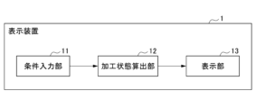
- FIG. 2 is a functional block diagram of a display device for a machine tool according to a first embodiment.
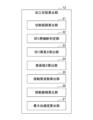
- FIG. 3 is a functional block diagram of a machining state calculation section. It is a figure which shows the cutting path as a machining state. It is a figure explaining the maximum distance between paths in a cutting path. It is a figure which shows the example of the image displayed on the input means and the display part of a processing state before a condition change. It is a figure which shows the other example of the image displayed on the input means and the display part of a processing state before a condition change. It is a figure which shows the example of the image displayed on the input means and the display part of a processing state after a condition change. It is a figure which shows the example of the image of the input means which clearly shows the range in which chips can be shredded according to the second embodiment.
- FIG. 3 is a functional block diagram of a display device for a machine tool according to a third embodiment.
- a display device 1 for a machine tool according to a first embodiment of the present invention is for performing swing cutting in which a workpiece is cut while relatively swinging a cutting tool and a workpiece. First, swing cutting will be explained with reference to FIG.
- FIG. 1 is a diagram for explaining oscillating cutting.
- swing cutting shown in FIG. (not shown) are operated to relatively rotate the cutting tool T and workpiece W, and perform cutting while relatively swinging the cutting tool T and workpiece W in the feeding direction.
- the tool path which is the locus of the cutting tool T, is set so that the current path partially overlaps the previous path.
- the part that was machined in the previous path is partially included in the current path, causing a miss called air cut in which the cutting edge of the cutting tool T separates from the surface of the workpiece W, and the chips are shredded.
- Ru is a diagram for explaining oscillating cutting.
- the shape of the workpiece is not limited. In other words, even if the workpiece has a tapered part or an arcuate part on the machined surface and requires multiple feed axes (Z-axis and X-axis), if the workpiece is columnar or cylindrical and the feed axis is (Z-axis) is also applicable.
- FIG. 2 is a functional block diagram of a display device 1 for a machine tool according to an embodiment of the present invention.
- the machine tool display device 1 of this embodiment includes, for example, memories such as ROM (read only memory) and RAM (random access memory), a CPU (control processing unit), and communication control units that are connected to each other via a bus. It is constructed using a computer with a section. The functions and operations of each of the functional units described above are achieved by the cooperation of a CPU installed in the computer, a memory, and a control program stored in the memory.
- the display device 1 of the machine tool may be composed of a CNC (Computer Numerical Controller), a PLC (Programmable Logic Controller), etc., or a host computer that outputs machining conditions such as rotation speed in addition to the machining program. may be connected to.
- CNC Computer Numerical Controller
- PLC Programmable Logic Controller
- host computer that outputs machining conditions such as rotation speed in addition to the machining program. may be connected to.
- the display device 1 of the machine tool includes a condition input section 11, a machining state calculation section 12, and a display section 13.
- the condition input unit 11 receives input of at least one of the machining conditions and the swing conditions using an input means that can continuously change input values.
- An input means that can continuously change input values.
- a configuration example of the input means will be described later.
- the machining conditions include at least information regarding the relative feed amount per revolution between the cutting tool and the workpiece, information regarding the shape of the cutting tool's cutting edge, and, for example, the rotation speed S (1/ min), the feed rate of the cutting tool (mm/min), the workpiece diameter (mm), the clearance angle of the cutting tool (°), and the like.
- Information regarding the relative feed amount per revolution between the cutting tool and the workpiece includes the amount of transfer each time F (mm/rev), and information regarding the shape of the cutting tool edge includes the R ( mm).
- the oscillation conditions include information regarding the relative number of oscillations per revolution between the cutting tool and the workpiece, and information regarding the oscillation amplitude with respect to the relative feed amount per revolution between the cutting tool and the workpiece.
- Information regarding the relative number of oscillations per rotation between the cutting tool and the workpiece includes an oscillation frequency multiplier I (times) indicating the oscillation frequency per one rotation of the main shaft.
- the swing amplitude magnification K indicates the magnitude of the swing amplitude relative to the feed amount per rotation of the spindle. (times) is mentioned.
- the oscillation frequency magnification I can be specified directly, or it can be calculated from the oscillation frequency (Hz) and the spindle rotation speed S (1/min) after specifying the oscillation frequency (Hz). good.
- the swing amplitude magnification K may be specified directly in the same way, or after specifying the swing amplitude (mm), the swing amplitude (mm), feed rate (mm/min), and spindle rotation speed can be specified. It may be calculated from S(1/min).
- the machining state calculation unit 12 calculates the machining state based on the machining conditions and swing conditions input from the condition input unit 11.
- the machining conditions include the cutting path, whether or not chips can be cut, the length of the chips, the surface roughness of the workpiece W, the rocking frequency in rocking, the vibration amplitude in rocking, the maximum acceleration in rocking, etc. .
- Y is the coordinate value of the feed direction (mm)
- f is the feed amount per spindle rotation F (mm/rev)
- S is the spindle Rotation speed (1/min)
- t is time (sec)
- I oscillation frequency magnification (times)
- K oscillation amplitude magnification (times)
- r is workpiece diameter (mm), which is the radius of workpiece W
- R is the cutting edge (mm), which is the shape of the cutting edge of the nose, etc.
- h is the maximum height Rz ( ⁇ m), which is an index of surface roughness.
- FIG. 3 is a functional block diagram of the machining state calculation unit 12.
- the machining state calculation unit 12 includes a cutting path calculation unit 21, a chip shredding determination unit 22, a chip length calculation unit 23, a surface roughness calculation unit 24, and a It includes a frequency calculation section 25, a swing amplitude calculation section 26, and a maximum acceleration calculation section 27.
- the cutting path calculation unit 21 calculates a relative cutting path between the cutting tool T and the workpiece W based on the machining conditions and the swing conditions.
- the processing conditions used to calculate the cutting path are, for example, the rotation speed S (1/min) of the spindle and the feed amount F (mm/rev) per spindle rotation.
- the oscillation conditions used to calculate the cutting path include, for example, the oscillation frequency multiplier I (times) indicating the oscillation frequency per rotation of the spindle and the magnitude of the oscillation amplitude relative to the feed amount per rotation of the spindle. is the swing amplitude magnification K (times).
- the cutting path calculation unit 21 calculates the coordinate value Y (mm) of the cutting path in the feed direction using the following formula (1), and derives the oscillation waveform as the cutting path.
- FIG. 4 is a diagram showing the cutting path.
- the cutting path calculation unit 21 outputs a graph in which formula (1) is plotted as a machining state 40 to the display unit 13.
- the oscillating waveform is shown as the machining state 40.
- the chip shredding determination unit 22 determines whether or not the chips can be shredded.
- the oscillation conditions used to determine whether or not the chips can be shredded are, for example, an oscillation frequency magnification I (times), which indicates the oscillation frequency per rotation of the spindle, and an oscillation amplitude magnification K (times), which indicates the magnitude of the oscillation amplitude relative to the magnitude of the feed amount per rotation of the spindle.
- the chip shredding determination unit 22 determines whether chips can be shredded using the following formula (2).
- the chip shredding determination unit 22 determines that chip cutting is possible when formula (2) is satisfied, and determines that chip cutting is not possible when formula (2) is not satisfied.
- the chip length calculation unit 23 calculates the length of chips of the workpiece W based on the machining conditions and the swing conditions.
- the processing condition used to calculate the chip length is, for example, the workpiece diameter (mm), which is the radius of the workpiece W.
- the swinging condition used to calculate the chip length is, for example, a swinging frequency magnification I (times) indicating the swinging frequency per rotation of the main shaft.
- the chip length calculation unit 23 calculates the chip length using the following formula (3).
- the surface roughness calculation unit 24 calculates the surface roughness of the W workpiece based on the machining conditions and the oscillation conditions.
- the machining conditions used to calculate the surface roughness are, for example, the feed rate F (mm/rev) per one rotation of the spindle and the cutting edge R (mm), which is the cutting edge shape of the cutting tool T.
- the oscillation conditions used to calculate the surface roughness are, for example, the oscillation frequency multiplier I (times), which indicates the oscillation frequency per one rotation of the shaft, and the oscillation amplitude multiplier K (times), which indicates the magnitude of the oscillation amplitude relative to the magnitude of the feed rate per one rotation of the spindle.
- the surface roughness calculated by the surface roughness calculation unit 24 includes at least one of the following: arithmetic mean roughness; maximum height, which is the maximum distance between a peak and a valley; maximum peak height, which is the maximum height from the mean line of the surface; maximum valley depth, which is the absolute value of the minimum height from the mean line of the surface; average height, which is the average value of the heights of the profile curve elements consisting of adjacent peaks and valleys as a set; maximum cross-sectional height, which is the sum of the maximum peak height and maximum valley depth of the profile curve element; and load length ratio, which is the ratio of the load length of the profile curve element at a specified cutting level (height % or ⁇ m) to the evaluation reference length.
- FIG. 5 is a diagram illustrating the maximum distance between cutting paths.
- FIG. 5 shows the location where the distance between the cutting paths is maximum.
- each coordinate value Y of the location where the distance between the cutting paths is the maximum is determined by the above formula (1), and the distance between the determined coordinate values is set as the maximum distance between the cutting paths.
- the maximum height Rz which is the maximum value of the distance between peaks and valleys, as surface roughness
- the R (mm) of the cutting edge and the maximum distance between the cutting paths calculated as described above are calculated.
- f is calculated as the maximum height Rz.
- the surface roughness is not limited to the maximum height Rz.
- the surface roughness may be, for example, the arithmetic mean roughness Ra.
- the oscillation frequency calculation unit 25 calculates the oscillation frequency in the relative oscillation of the cutting tool T and the workpiece W based on the machining conditions and the oscillation conditions.
- the machining conditions used to calculate the oscillation frequency are, for example, the rotation speed S (1/min) of the spindle.
- the oscillation conditions used to calculate the oscillation frequency are, for example, the oscillation frequency magnification I (times) indicating the oscillation frequency per rotation of the spindle.
- the oscillation frequency calculation unit 25 calculates the oscillation frequency using the following formula (5).
- the swing amplitude calculation unit 26 calculates the swing amplitude in the relative swing between the cutting tool T and the workpiece W based on the machining conditions and the swing conditions.
- the processing condition used to calculate the swing amplitude is, for example, the transfer amount F (mm/rev) each time.
- the swing condition used to calculate the swing amplitude is, for example, a swing amplitude magnification K (times) that indicates the magnitude of the swing amplitude relative to the feed amount per rotation of the main shaft.
- the swing amplitude calculation unit 26 calculates the swing amplitude using the following formula (6).
- the maximum acceleration calculation unit 27 calculates the maximum acceleration in the relative oscillation of the cutting tool T and the workpiece W based on the machining conditions and the oscillation conditions.
- the machining conditions used to calculate the maximum acceleration are, for example, the spindle rotation speed S (1/min) and the feed rate F (mm/rev).
- the oscillation conditions used to calculate the maximum acceleration are, for example, the oscillation amplitude magnification K (times) indicating the magnitude of the oscillation amplitude relative to the magnitude of the feed rate per rotation of the spindle, and the oscillation frequency magnification I (times) indicating the oscillation frequency per rotation of the spindle.
- the maximum acceleration calculation unit 27 calculates the maximum acceleration using the following formula (7).
- processing state calculation unit 12 The above describes the configuration of the processing state calculation unit 12. Note that the above-mentioned determination method and calculation method are merely examples, and the processing state may be calculated using a method other than the method using the above-mentioned formula.
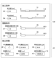
- FIG. 6 is a diagram showing an example of an image displayed on the display unit 13 of the input means and processing state before the conditions are changed.
- the display unit 13 displays both the input means 30 for inputting the machining conditions and swing conditions, and the machining state 41 calculated by the machining state calculation unit 12. Furthermore, in this embodiment, it is assumed that a machining state 40 showing the oscillating waveform shown in FIG. 4 is also displayed on the display section 13 in conjunction with the display shown in FIG.
- a slider bar 31 for inputting the feed amount F [mm] and a slider bar 32 for inputting the cutting edge R [mm] are displayed.
- a window 33 is displayed that numerically indicates the input result of the feed amount F [mm].
- the operator operates the slider bar and inputs 0.2 as a numerical value.
- a window 34 is displayed that numerically indicates the input result of the cutting edge R [mm].
- the operator operates the slider bar and inputs 0.4 as a numerical value. It is assumed that the rotational speed S (1/min) of the main shaft and the like are set in advance or by another input means.
- the block in which the rocking conditions of the input means 30 are displayed includes a slider bar 35 for inputting the rocking frequency magnification I (times) and a slider bar 36 for inputting the rocking amplitude magnification K (times). Is displayed. On the left side of the slider bar 35, a window 37 is displayed that numerically indicates the input result of the oscillation frequency magnification I (times). In this example, the operator operates the slider bar 35 and inputs 1.5 as a numerical value. On the left side of the slider bar 36, a window 38 is displayed that numerically indicates the input result of the swing amplitude magnification K (times). In this example, the operator operates the slider bar 36 and inputs 1.2 as a numerical value.
- FIG. 7 is a diagram showing another example of the image displayed on the input means and the processing state display section before the conditions are changed.
- a scroll bar is used to input both machining conditions and swing conditions, but as shown in Fig. 7, a slider bar is used for some of the processing conditions and swing conditions. Also good.
- only conditions that need to be checked continuously can be entered using the scroll bar, and conditions that can be checked intermittently can be entered using numerical values.
- the output result of the machining state calculation unit 12 is displayed.
- a symbol indicates that the chips can be shredded.
- a window 43 displays the calculation result of the chip length [mm]
- a window 44 displays the calculation result of the maximum height Rz [ ⁇ m], which is an index of surface roughness
- a window 44 displays the calculation result of the frequency [Hz].
- a window 47 for displaying the calculation results for the maximum acceleration [mm/s 2 ] display numerical values based on the machining conditions and the swing conditions, respectively. There is.
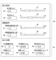
- FIG. 8 is a diagram showing an example of an image displayed on the input means and processing state display unit after the conditions have been changed.
- the feed amount F [mm] of the machining conditions has been changed from 0.2 to 0.3, and the cutting edge R [mm], the swing amplitude magnification K (times), and the swing frequency multiplier
- the value of I (times) remains the same.
- the machining state calculation unit 12 determines and calculates the machining state 41 again based on the input result.
- FIG. 8 is a diagram showing an example of an image displayed on the input means and processing state display unit after the conditions have been changed.
- the feed amount F [mm] of the machining conditions has been changed from 0.2 to 0.3
- the cutting edge R [mm] the cutting edge
- the swing amplitude magnification K (times) times
- the swing frequency multiplier The value of I (times) remains the same.
- the maximum height Rz [ ⁇ m] shown in the window 44 changes from 50.0 to 112.5
- the amplitude [mm] shown in the window 46 changes from 0.240 to 0.360
- the maximum height Rz [ ⁇ m] shown in the window 47 changes from 0.240 to 0.360.
- the maximum acceleration [mm/s 2 ] shown is from 18505.5 to 27758.3. Note that the output results of the determination result of whether or not chips can be cut from the window 42, the numerical value of the chip length [mm] of the window 43, and the numerical value of the frequency [Hz] remain the same.
- the machining state calculation unit 12 also re-outputs the machining state 40 of the oscillation waveform (cutting path) shown in Figure 4 based on the changed input conditions, and outputs it to the display unit 13.
- the slider bar 31 is the input part for the feed amount F [mm]
- the slider bar 32 is the input part for the cutting edge R [mm]
- the slider bar 35 is the input part for the oscillation frequency magnification I [times]
- the oscillation When at least one of the slider bars 36, which is the input section for the amplitude magnification K [times], is operated, the judgment result corresponding to the changed input value among the cutting path machining state 40 and other machining states 41 is displayed.
- the numbers change synchronously.
- the machine tool display device 1 In the machine tool display device 1 according to the present embodiment, at least one of the machining conditions and the swing conditions is inputted using the input means 30 (slider bars 31, 32, 35, 36) that can continuously change the input value.
- the machine includes a condition input section 11 that receives a condition, a machining state calculation section 12 that calculates a machining state according to input of machining conditions and swing conditions, and a display section 13 that displays the calculated machining state.
- the machining state calculation unit 12 of the present embodiment includes a cutting path calculation unit 21 that calculates a relative cutting path between the cutting tool T and the workpiece W, and a chip shredding determination unit 22 that determines whether chips can be shredded. , a chip length calculation section 23 that calculates the length of chips on the workpiece W, a surface roughness calculation section 24 that calculates the surface roughness of the workpiece W, and a relative vibration between the cutting tool T and the workpiece W.
- a swing frequency calculation unit 25 that calculates the swing frequency in the relative swing between the cutting tool T and the workpiece W
- a swing amplitude calculation unit 26 that calculates the swing amplitude in the relative swing between the cutting tool T and the workpiece W
- It has at least one or more of the maximum acceleration calculation section 27 that calculates the maximum acceleration in relative rocking.
- information regarding the relative feed amount per rotation (feed amount F) between the cutting tool T and workpiece W, and the relative number of oscillations per rotation between the cutting tool T and workpiece W are the cutting path calculation unit of the machining state calculation unit 12. 21. This allows input work to be performed while checking the cutting path that is re-outputted in synchronization with the input value.
- information regarding the relative number of oscillations per rotation between the cutting tool T and the workpiece W (oscillation frequency multiplier I) and the relative feed rate per rotation between the cutting tool T and the workpiece W are provided.
- Information regarding the oscillation amplitude (oscillation amplitude magnification K) with respect to the amount is input to the chip shredding determination section 22 of the machining state calculation section 12. This makes it possible to perform input work while checking the determination results that are output in synchronization with the input values.
- information regarding the relative number of oscillations per revolution between the cutting tool T and the workpiece W (oscillation frequency multiplier I) and the relative distance from the center of rotation between the cutting tool T and the workpiece W are provided. (workpiece diameter (mm)) is input to the chip length calculation unit 23 of the machining state calculation unit 12. You can perform input work while checking the chip length that is output in synchronization with the input value.
- the relative feed amount per revolution (feed amount F) between the cutting tool T and the work W, the shape of the cutting tool T (blade edge R), and the relative feed amount (feed amount F) between the cutting tool T and the work W Information regarding the number of oscillations per revolution (oscillation frequency multiplier I), information regarding the oscillation amplitude with respect to the relative feed amount per revolution between the cutting tool T and the workpiece W (oscillation amplitude multiplier K). is input to the surface roughness calculation section 24 of the machining state calculation section 12. Thereby, it is possible to more easily perform the input work while checking the index (maximum height Rz) indicating the surface roughness that is re-outputted in synchronization with the input value.
- the relative feed amount per revolution (feed amount F) between the cutting tool T and workpiece W, and the swing amplitude with respect to the relative feed amount per revolution between the cutting tool T and workpiece W. (oscillation amplitude magnification K) is input to the oscillation amplitude calculation section 26 of the machining state calculation section 12. This makes it easier to perform the input work while checking the amplitude that is re-outputted in synchronization with the input value.
- the oscillation amplitude magnification K) is input to the maximum acceleration calculation section 27 of the machining state calculation section 12. This makes it easier to perform the input work while checking the maximum acceleration that is re-outputted in synchronization with the input value.
- FIG. 9 is a diagram showing an example of an image of the input means 30a that clearly shows the range in which chips can be shredded according to the second embodiment.
- the slider bar 35a which is the input part for the rocking frequency magnification I [times] of the rocking condition
- the slider bar 36a which is the input part for the rocking amplitude magnification K [times]
- the range and the range where chip cutting is not possible are distinguished by color and displayed. Note that whether or not the range is within which chips can be shredded may be set in advance by the operator, or may be set by the chip shredding determination unit 22 based on a value input in advance.
- the range in which chips can be cut and the range in which chips cannot be cut are displayed in alternating colors in the longitudinal direction of the slider bar 35a, and the range in which chips cannot be cut is displayed in alternating colors.
- the possible range is an intermittent arrangement.
- the color indicates that almost the entire input range except the left end part is the range in which chips can be cut.
- condition input unit 11 sets the input means 30 to accept user operations only in the range where chips can be cut on both the slider bar 35a and the slider bar 36a. Therefore, the operator cannot move the slider bar 35a and the slider bar 36a to a range where chips cannot be cut.
- the condition input unit 11 clearly indicates the range in which the chips can be shredded on the input means 30a (slider bar 35a and slider bar 36a). This allows the user to easily grasp the range in which the chips can be shredded and smoothly proceed with the input work on the input means 30a.
- condition input unit 11 of the second embodiment sets the changeable range of the input means 30 based on the range in which the chips can be shredded. This ensures that the input value is set only within the range in which the chips can be cut, and it is possible to reliably prevent situations in which the chips are not shredded appropriately.
- the display is distinguished by color, but the display may be distinguished by shape or the like.
- Fig. 10 is a functional block diagram of a display device 1a of a machine tool according to the third embodiment. As shown in Fig. 10, the display device 1A of a machine tool according to the third embodiment is different from the display device 1 of a machine tool according to the first embodiment in that it includes a condition range acquisition unit 14, and other configurations are the same as those of the first embodiment.
- the range of the machining conditions and the swing conditions can be specified.
- the condition range acquisition unit 14 acquires the range of processing conditions and swing conditions from an input unit such as a keyboard or a touch display, or an input means (not shown) such as an external computer.
- the range of processing conditions is, for example, the range of feed amount [mm] and the range of cutting edge [mm].
- the operator can specify the feed amount [mm] range from 0 to 1.0 or a different range through input means (not shown), or specify the cutting edge [mm] range from 0 to 1.0 or a different range. You can also specify.
- the range of the rocking conditions is, for example, the range of the rocking frequency magnification I [times] or the range of the rocking amplitude magnification K [times].
- the operator may specify the range of the oscillation frequency multiplier I [times] to 0 to 16.0 or a different range, or specify the range of the oscillation amplitude multiplier K [times] from 0 to 16.0 through an input means (not shown). It can be specified as 0 or a range different from that.
- the machine tool display device 1a of the third embodiment further includes a condition range acquisition section 14 that acquires the range of machining conditions and swing conditions that can be input, and the condition input section 11
- the acquisition unit 14 receives input of machining conditions and swing conditions based on the input range acquired. This results in a prespecified input range, making it possible to realize an interface that is easier for operators to use depending on the situation.
- the configuration of the machining state calculation unit 12 of the above embodiment can be changed as appropriate depending on the circumstances, such as omitting some functions or adding other functions.
- the configuration of the third embodiment may be combined with the configuration of the second embodiment.
- the display unit 13 may be configured to display items different from those described in the above embodiments.
Landscapes
- Engineering & Computer Science (AREA)
- Human Computer Interaction (AREA)
- Manufacturing & Machinery (AREA)
- Physics & Mathematics (AREA)
- General Physics & Mathematics (AREA)
- Automation & Control Theory (AREA)
- Mechanical Engineering (AREA)
- Machine Tool Sensing Apparatuses (AREA)
- Automatic Control Of Machine Tools (AREA)
- Numerical Control (AREA)
Priority Applications (5)
| Application Number | Priority Date | Filing Date | Title |
|---|---|---|---|
| DE112022007516.3T DE112022007516T5 (de) | 2022-09-21 | 2022-09-21 | Anzeigevorrichtung für Werkzeugmaschinen |
| CN202280100022.8A CN119866478A (zh) | 2022-09-21 | 2022-09-21 | 机床的显示装置 |
| US19/108,929 US20260086535A1 (en) | 2022-09-21 | 2022-09-21 | Display device for machine tool |
| PCT/JP2022/035088 WO2024062544A1 (ja) | 2022-09-21 | 2022-09-21 | 工作機械の表示装置 |
| JP2024547985A JPWO2024062544A1 (cg-RX-API-DMAC7.html) | 2022-09-21 | 2022-09-21 |
Applications Claiming Priority (1)
| Application Number | Priority Date | Filing Date | Title |
|---|---|---|---|
| PCT/JP2022/035088 WO2024062544A1 (ja) | 2022-09-21 | 2022-09-21 | 工作機械の表示装置 |
Publications (1)
| Publication Number | Publication Date |
|---|---|
| WO2024062544A1 true WO2024062544A1 (ja) | 2024-03-28 |
Family
ID=90454006
Family Applications (1)
| Application Number | Title | Priority Date | Filing Date |
|---|---|---|---|
| PCT/JP2022/035088 Ceased WO2024062544A1 (ja) | 2022-09-21 | 2022-09-21 | 工作機械の表示装置 |
Country Status (5)
| Country | Link |
|---|---|
| US (1) | US20260086535A1 (cg-RX-API-DMAC7.html) |
| JP (1) | JPWO2024062544A1 (cg-RX-API-DMAC7.html) |
| CN (1) | CN119866478A (cg-RX-API-DMAC7.html) |
| DE (1) | DE112022007516T5 (cg-RX-API-DMAC7.html) |
| WO (1) | WO2024062544A1 (cg-RX-API-DMAC7.html) |
Cited By (2)
| Publication number | Priority date | Publication date | Assignee | Title |
|---|---|---|---|---|
| JP7710621B1 (ja) * | 2024-05-27 | 2025-07-18 | 三菱電機株式会社 | 設定支援装置、数値制御装置、設定支援方法およびプログラム |
| JP7814642B1 (ja) * | 2025-06-20 | 2026-02-16 | 三菱電機株式会社 | 数値制御装置、数値制御システムおよび数値制御方法 |
Citations (8)
| Publication number | Priority date | Publication date | Assignee | Title |
|---|---|---|---|---|
| JP2003058218A (ja) * | 2001-06-06 | 2003-02-28 | Fanuc Ltd | サーボモータを駆動制御する制御装置 |
| WO2018117203A1 (ja) * | 2016-12-22 | 2018-06-28 | シチズン時計株式会社 | 工作機械およびその制御装置 |
| JP2019503879A (ja) * | 2016-02-03 | 2019-02-14 | ミルウォーキー エレクトリック ツール コーポレイション | レシプロソーを設定するシステム及び方法 |
| JP2019191857A (ja) * | 2018-04-24 | 2019-10-31 | ファナック株式会社 | 表示装置 |
| JP2021047520A (ja) * | 2019-09-17 | 2021-03-25 | 株式会社ジェイテクト | 作業支援システム |
| JP2021070089A (ja) * | 2019-10-30 | 2021-05-06 | オークマ株式会社 | 工作機械における主軸回転速度のモニタ装置及びモニタ方法、工作機械 |
| JP2021096839A (ja) * | 2019-12-16 | 2021-06-24 | ファナック株式会社 | 工作機械の制御装置及び工作機械制御方法 |
| WO2022181594A1 (ja) * | 2021-02-26 | 2022-09-01 | ファナック株式会社 | 計算装置 |
-
2022
- 2022-09-21 CN CN202280100022.8A patent/CN119866478A/zh active Pending
- 2022-09-21 WO PCT/JP2022/035088 patent/WO2024062544A1/ja not_active Ceased
- 2022-09-21 US US19/108,929 patent/US20260086535A1/en active Pending
- 2022-09-21 JP JP2024547985A patent/JPWO2024062544A1/ja active Pending
- 2022-09-21 DE DE112022007516.3T patent/DE112022007516T5/de active Pending
Patent Citations (8)
| Publication number | Priority date | Publication date | Assignee | Title |
|---|---|---|---|---|
| JP2003058218A (ja) * | 2001-06-06 | 2003-02-28 | Fanuc Ltd | サーボモータを駆動制御する制御装置 |
| JP2019503879A (ja) * | 2016-02-03 | 2019-02-14 | ミルウォーキー エレクトリック ツール コーポレイション | レシプロソーを設定するシステム及び方法 |
| WO2018117203A1 (ja) * | 2016-12-22 | 2018-06-28 | シチズン時計株式会社 | 工作機械およびその制御装置 |
| JP2019191857A (ja) * | 2018-04-24 | 2019-10-31 | ファナック株式会社 | 表示装置 |
| JP2021047520A (ja) * | 2019-09-17 | 2021-03-25 | 株式会社ジェイテクト | 作業支援システム |
| JP2021070089A (ja) * | 2019-10-30 | 2021-05-06 | オークマ株式会社 | 工作機械における主軸回転速度のモニタ装置及びモニタ方法、工作機械 |
| JP2021096839A (ja) * | 2019-12-16 | 2021-06-24 | ファナック株式会社 | 工作機械の制御装置及び工作機械制御方法 |
| WO2022181594A1 (ja) * | 2021-02-26 | 2022-09-01 | ファナック株式会社 | 計算装置 |
Cited By (3)
| Publication number | Priority date | Publication date | Assignee | Title |
|---|---|---|---|---|
| JP7710621B1 (ja) * | 2024-05-27 | 2025-07-18 | 三菱電機株式会社 | 設定支援装置、数値制御装置、設定支援方法およびプログラム |
| WO2025248583A1 (ja) * | 2024-05-27 | 2025-12-04 | 三菱電機株式会社 | 設定支援装置、数値制御装置、設定支援方法およびプログラム |
| JP7814642B1 (ja) * | 2025-06-20 | 2026-02-16 | 三菱電機株式会社 | 数値制御装置、数値制御システムおよび数値制御方法 |
Also Published As
| Publication number | Publication date |
|---|---|
| JPWO2024062544A1 (cg-RX-API-DMAC7.html) | 2024-03-28 |
| US20260086535A1 (en) | 2026-03-26 |
| DE112022007516T5 (de) | 2025-07-31 |
| CN119866478A (zh) | 2025-04-22 |
Similar Documents
| Publication | Publication Date | Title |
|---|---|---|
| EP3214513B1 (en) | Control method for machining tool and control device for machining tool | |
| JP7252426B1 (ja) | 工作機械の制御装置及び工作機械の表示装置 | |
| WO2022181594A1 (ja) | 計算装置 | |
| WO2024062544A1 (ja) | 工作機械の表示装置 | |
| EP3045988A1 (en) | Toolpath evaluation method, toolpath generation method, and toolpath generation device | |
| CN116157220B (zh) | 数控装置及数控方法 | |
| CN107678396A (zh) | 加工状态显示装置及具备该装置的nc程序生成和编辑装置 | |
| JP4639058B2 (ja) | ねじ切り加工装置 | |
| JP2004206723A (ja) | 工具製造装置及び製造方法 | |
| KR101078800B1 (ko) | 외장형 파트프로그램 작성장치 | |
| JP7827830B2 (ja) | 表示装置およびコンピュータ読み取り可能な記憶媒体 | |
| JP7039772B1 (ja) | 表示装置、工作機械、および表示方法 | |
| WO2024232100A1 (ja) | 工作機械の表示装置、工作機械の制御装置及びプログラム | |
| JP7827878B2 (ja) | 工作機械の制御装置及び工作機械の表示装置 | |
| WO2024232099A1 (ja) | 計算装置 | |
| JP7799048B2 (ja) | 工作機械の制御装置 | |
| JP7794960B2 (ja) | 工作機械の制御装置 | |
| WO2024232103A1 (ja) | 工作機械の表示装置 | |
| CN121039588A (zh) | 机床的显示装置以及程序 | |
| CN121152706A (zh) | 机床的显示装置 | |
| CN119894636A (zh) | 机床的控制装置 | |
| WO2024189907A1 (ja) | 加工経路表示装置およびコンピュータ読み取り可能な記憶媒体 | |
| WO2024214301A1 (ja) | 指令生成装置およびコンピュータ読み取り可能な記憶媒体 | |
| WO2024154314A1 (ja) | 工作機械の制御装置 | |
| CN120282849A (zh) | 机床的控制装置 |
Legal Events
| Date | Code | Title | Description |
|---|---|---|---|
| 121 | Ep: the epo has been informed by wipo that ep was designated in this application |
Ref document number: 22959508 Country of ref document: EP Kind code of ref document: A1 |
|
| WWE | Wipo information: entry into national phase |
Ref document number: 2024547985 Country of ref document: JP |
|
| WWE | Wipo information: entry into national phase |
Ref document number: 112022007516 Country of ref document: DE |
|
| WWE | Wipo information: entry into national phase |
Ref document number: 202280100022.8 Country of ref document: CN |
|
| WWP | Wipo information: published in national office |
Ref document number: 202280100022.8 Country of ref document: CN |
|
| WWP | Wipo information: published in national office |
Ref document number: 112022007516 Country of ref document: DE |
|
| 122 | Ep: pct application non-entry in european phase |
Ref document number: 22959508 Country of ref document: EP Kind code of ref document: A1 |