WO2024057627A1 - 物体認識装置、ロボットシステム、および、物体認識方法 - Google Patents
物体認識装置、ロボットシステム、および、物体認識方法 Download PDFInfo
- Publication number
- WO2024057627A1 WO2024057627A1 PCT/JP2023/019831 JP2023019831W WO2024057627A1 WO 2024057627 A1 WO2024057627 A1 WO 2024057627A1 JP 2023019831 W JP2023019831 W JP 2023019831W WO 2024057627 A1 WO2024057627 A1 WO 2024057627A1
- Authority
- WO
- WIPO (PCT)
- Prior art keywords
- article
- area
- object recognition
- recognition device
- group
- Prior art date
- Legal status (The legal status is an assumption and is not a legal conclusion. Google has not performed a legal analysis and makes no representation as to the accuracy of the status listed.)
- Ceased
Links
Images


Classifications
-
- G—PHYSICS
- G06—COMPUTING OR CALCULATING; COUNTING
- G06V—IMAGE OR VIDEO RECOGNITION OR UNDERSTANDING
- G06V20/00—Scenes; Scene-specific elements
- G06V20/50—Context or environment of the image
-
- B—PERFORMING OPERATIONS; TRANSPORTING
- B25—HAND TOOLS; PORTABLE POWER-DRIVEN TOOLS; MANIPULATORS
- B25J—MANIPULATORS; CHAMBERS PROVIDED WITH MANIPULATION DEVICES
- B25J13/00—Controls for manipulators
-
- B—PERFORMING OPERATIONS; TRANSPORTING
- B25—HAND TOOLS; PORTABLE POWER-DRIVEN TOOLS; MANIPULATORS
- B25J—MANIPULATORS; CHAMBERS PROVIDED WITH MANIPULATION DEVICES
- B25J9/00—Program-controlled manipulators
- B25J9/16—Program controls
- B25J9/1694—Program controls characterised by use of sensors other than normal servo-feedback from position, speed or acceleration sensors, perception control, multi-sensor controlled systems, sensor fusion
- B25J9/1697—Vision controlled systems
-
- G—PHYSICS
- G06—COMPUTING OR CALCULATING; COUNTING
- G06T—IMAGE DATA PROCESSING OR GENERATION, IN GENERAL
- G06T7/00—Image analysis
- G06T7/10—Segmentation; Edge detection
- G06T7/11—Region-based segmentation
-
- G—PHYSICS
- G06—COMPUTING OR CALCULATING; COUNTING
- G06T—IMAGE DATA PROCESSING OR GENERATION, IN GENERAL
- G06T7/00—Image analysis
- G06T7/70—Determining position or orientation of objects or cameras
- G06T7/73—Determining position or orientation of objects or cameras using feature-based methods
-
- G—PHYSICS
- G06—COMPUTING OR CALCULATING; COUNTING
- G06V—IMAGE OR VIDEO RECOGNITION OR UNDERSTANDING
- G06V10/00—Arrangements for image or video recognition or understanding
- G06V10/70—Arrangements for image or video recognition or understanding using pattern recognition or machine learning
- G06V10/74—Image or video pattern matching; Proximity measures in feature spaces
-
- G—PHYSICS
- G06—COMPUTING OR CALCULATING; COUNTING
- G06V—IMAGE OR VIDEO RECOGNITION OR UNDERSTANDING
- G06V20/00—Scenes; Scene-specific elements
- G06V20/60—Type of objects
- G06V20/64—Three-dimensional [3D] objects
Definitions
- the present invention relates to an object recognition device, a robot system, and an object recognition method.
- a cargo handling control device disclosed in Patent Document 1 is known as a conventional technique that allows recognition of a group of articles entirely wrapped in transparent wrap as a single object to be transported.
- the abstract of Patent Document 1 describes the problem of ⁇ properly moving articles even when a plurality of articles are grouped together with a sheet-like cover,'' and the problem is solved.
- the cargo handling control according to the embodiment includes a transmitting/receiving section and a control section.
- the controller transmits an ultrasonic wave or a radio wave as a transmission wave in the direction in which the writing section is present, and receives a reflected wave of the transmission wave.
- the control section determines that the plurality of articles are covered by a sheet-like covering based on the recognition result based on the captured image and the reception result of the reflected wave of the transmitter/receiver. It is determined whether or not the cargoes are grouped together, and the cargo handling device is controlled based on the determined result.”
- Covering B is a transparent or translucent vinyl sheet, etc..
- Covering B is a wrapping sheet, a wrapping sheet (sheet ), also called shrink film (film).
- the cargo handling control device of Patent Document 1 is equipped with a sensor device 20 on the gripping portion 113 at the tip of the robot arm, and the sensor device 20 transmits and receives ultraviolet light.
- the sensor device 20 transmits and receives ultraviolet light.
- the present invention provides an object recognition device and an object recognition method that can recognize a group of conveyed objects (the same article group) as a conveyance unit based on the arrangement of individual articles in the article group.
- the purpose is to provide
- an object recognition device of the present invention is an object recognition device that recognizes a group of the same articles as a transport unit in an environment where a plurality of articles exist, and acquires images of the plurality of articles.
- an input unit an article detection unit that detects an article area in which the article exists from the image, and obtains information between each article area, which is information regarding the arrangement of the article area, and calculates a frequency distribution of the information between the article areas.
- the object recognition apparatus further includes a same article group area estimating section that estimates an area of the same article group based on the frequency distribution.
- the object recognition device and the object recognition method of the present invention it is possible to recognize a group of conveyed objects (the same group of articles), which is a conveyance unit, based on the arrangement of individual articles within the group of articles.
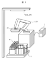
- FIG. 1 is a schematic diagram showing a usage environment of the object recognition device of Example 1.
- FIG. 1 is a block diagram showing a hardware configuration of an object recognition device according to a first embodiment.
- FIG. 2 is a functional block diagram of the object recognition device according to the first embodiment.
- FIG. 3 is a diagram for explaining processing of an article detection section and a same article area estimation section.
- FIG. 7 is a diagram for explaining the processing of the object recognition device according to the second embodiment.
- FIG. 7 is a diagram for explaining the processing of the object recognition device according to the third embodiment.
- FIGS. 1 to 4 An object recognition device 1 according to a first embodiment of the present invention and a robot system using the same will be explained using FIGS. 1 to 4.
- FIG. 1 is a schematic diagram showing the environment in which the object recognition device 1 is used.
- 2 is a multi-joint arm robot (hereinafter simply referred to as "robot") that has a multi-joint arm 21 and a hand 22 and is controlled by the object recognition device 1
- 3 is a left camera 3L and a right camera 3R.
- a stereo camera that transmits synchronously captured stereo images to the object recognition device 1
- 4 is a variety of articles (for example, plastic bottles, toilet paper, cardboard boxes, etc.) conveyed by the robot 2
- 5 is a pallet on which the articles 4 are placed; It is.
- the robot 2 is installed at a location where it can grip any article 4 on the pallet 5 with the hand 22 by moving the multi-joint arm 21, and the stereo camera 3 5 is installed in a location where the entire top surface of the camera can be imaged.
- FIG. 2 is a block diagram showing the hardware configuration of the object recognition device 1.
- the object recognition device 1 includes a processor 11 such as a CPU, a storage device 12 such as a semiconductor memory, an input device 13 such as a keyboard and a mouse, an output device 14 such as a liquid crystal display, a robot 2 and a stereo camera 3.
- the computer is equipped with a communication interface 15 for communication, a bus 16 for connecting them, and the like. It is assumed that when the processor 11 executes the object recognition processing program 12a stored in the storage device 12, an article group area estimating section 11b identical to the article detecting section 11a, which will be described later, is realized.
- FIG. 3 is a functional block diagram of the object recognition device 1.
- the object recognition device 1 includes an input section 15a that receives a stereo image from the stereo camera 3, an article detection section 11a that detects an article 4 by processing the received stereo image, and an input section 11a that detects an article 4 by processing the received stereo image.
- the same article group area estimating unit 11b estimates the same article area corresponding to the transport unit by focusing on the arrangement of the same article area, and the output unit 15b sends a command to the robot 2 based on the estimated position of the same article area.
- the input section 15a and the output section 15b are functional sections realized by the communication interface 15 in FIG.
- the articles 4 transported by the robot 2 are PET bottles, and nine PET bottles in a 3x3 array are wrapped entirely in transparent wrap or bound on the sides and bottom with transparent wrap. This shall be carried out as a transport unit (one block of objects to be transported).
- Step S1 acquires imaging information of the subject based on a stereo image captured by the stereo camera 3. Since the left camera 3L and right camera 3R of the stereo camera 3 are placed apart from each other by a predetermined distance, when comparing the left image taken by the left camera 3L and the right image taken by the right camera 3R, the difference is determined depending on the distance to the subject. parallax is observed. Therefore, the article detection unit 11a can calculate the distance to the photographed object by applying the principle of triangulation to process the stereo images.
- the captured image itself may be acquired as the imaging information.
- step S2 the article detection unit 11a detects an article region where each plastic bottle (article 4) exists based on the imaging information acquired in step S1.
- step S1 since the distance to the subject is calculated, each of the flat circular areas on the same plane as shown in the image diagram of FIG. 4(a) is , plastic bottle cap) can be extracted as an article region where the object exists.
- individual PET bottles can be identified by pattern matching between the image as the imaging information and the known top view shape and color of the plastic bottle (article 4). ) may be extracted.
- Step S3 (obtaining information between each article area)>>
- the same article group area estimating unit 11b acquires inter-article area information regarding the arrangement of the article areas detected in step S2. Specifically, as shown in the image diagram of FIG. 4(b), the same article group area estimating unit 11b calculates the vertically or horizontally adjacent article areas in the image for each article area detected in step S2. The distance (indicated by a solid line in FIG. 4(b)) is calculated and acquired as information between each article area. Note that the angle between adjacent article regions and the normal direction of each article region may be used as information between each article region. Furthermore, the pattern information may also be used as inter-article area information.
- Step S4 (Calculation of Frequency Distribution)>>>
- the same item group area estimation unit 11b calculates a frequency distribution of each item area information (distance, angle, normal direction) acquired in step S3. For example, as shown in the right graph in Fig. 4(c), the same item group area estimation unit 11b first arranges distance information, which is one type of item area information acquired in step S3, on a graph with item-to-item distance on the horizontal axis and frequency on the vertical axis. In this example, two types of item-to-item distances, a high frequency distance group shown by a solid line and a low frequency distance group shown by a dotted line, are calculated as the frequency distribution of each item area information. Note that a graph is also created in the same way when each item area information is angle or normal direction information.
- step S5 the same article group area estimation unit 11b estimates the same article group area based on the frequency distribution calculated in step S4.
- the distances between the articles 4 include a relatively short distance group indicated by a solid line and a relatively long distance group indicated by a dotted line. Since the latter distance group is considered to be the distance between transportation units, the same article group area estimating unit 11b considers the portion indicated by the dotted line where the distance between the articles 4 is relatively long as the boundary between the transportation units.
- FIG. 4(d) two regions of the same object group are estimated. The positional information of the two same object group regions estimated here is transmitted to the control unit of the robot 2 via the output unit 15b, and the robot 2 transports nine plastic bottles (item 4) in a 3x3 array. Used to properly grip the unit.
- the probability that the imaged object group is one same object group region and the probability that the imaged object group is a plurality of same object group regions may be calculated and output to the outside. This allows the robot 2 to decide on an action based on both possibilities.
- Various methods can be used to calculate the probability; for example, the relative frequency may be directly output as a probability, or a clustering method such as K-means may be used.
- the object to be conveyed in one lump which is the unit of conveyance, is Can recognize objects (same group of objects).
- the robot 2 can move the hand 22 to an appropriate position for grasping a block of objects to be transported wrapped in transparent wrap or the like.
- Example 1 when nine PET bottles arranged in a 3x3 arrangement (article 4) are entirely wrapped in transparent wrap, the stereo camera 3 can clearly image the position of each individual PET bottle (article 4). Therefore, as shown in FIG. 5(a), it was possible to easily obtain information between each article area (distance information between articles).
- step S3 of this embodiment when the same article group region estimating unit 11b acquires the information between each article region, the distance between the pattern 6 and the article 4, the distance between the pattern 6 and the article 4, and the distance between the pattern 6 and the article 4 as shown in FIG. It was decided to acquire the angle of the article 4 or the normal direction of the pattern 6 as information between each article area.
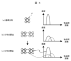
- FIG. 6 An object recognition device 1 according to a third embodiment of the present invention will be described using FIG. 6. Note that redundant explanation of common points with the above embodiments will be omitted.
- the characteristics of the group of articles serving as the transportation unit were unknown, it was necessary to estimate the mode of the transportation unit based on the image each time it was captured.
- the characteristics (frequency distribution of information between each article area) of a group of articles that are a unit of transportation are known, and based on the known characteristics (frequency distribution of information between each article area), It is possible to extract groups.
- the same article group area estimating unit 11b of this embodiment The frequency distribution of information between each article area is registered in advance as a reference, as shown in the right graph of FIG. 6(a).
- the eight plastic bottles (article 4) imaged by the stereo camera 3 are arranged as shown in FIG. 6(b), and the frequency distribution of information between each article region calculated from the image is b)
- the solid line distance matches the characteristics of the standard transport unit (frequency distribution of information between each article area)
- the dashed line distance does not match the characteristics of the reference transport unit (frequency distribution of information between each article area)
- correction processing can be performed to emphasize the frequency of the solid line group.
- the object recognition device 1 of this embodiment eight PET bottles (articles 4) in a 2 ⁇ 4 array are placed in the same article group area consisting of four PET bottles (articles 4) in a 2 ⁇ 2 array. It can be divided into two parts correctly.
- a template of an area that includes two or more article areas or a pattern feature obtained from the area is used as inter-article area information.
- the item 4 to be transported is a plastic bottle
- the cap of the bottle has a pattern drawn on it, and the orientation of the pattern is always the same within the same group of items
- the horizontal axis is The value of the pattern feature amount
- the vertical axis is the frequency
- the distribution is calculated, and based on this calculation result, the difference in the template or the difference in the pattern feature amount (difference in the horizontal axis of the frequency distribution) is calculated, and the orientation of the pattern is calculated.
- Object Recognition Device 11 Processor 11a Article Detection Unit 11b Same Article Group Area Estimation Unit 12 Storage Device 12a Object Recognition Processing Program 13 Input Device 14 Output Device 15 Communication Interface 15a Input Unit 15b Output Unit 16 Bus 2 Robot 21 Articulated Arm 22 Hand 3 Stereo camera 3L Left camera 3R Right camera 4 Article 5 Pallet 6 Pattern
Landscapes
- Engineering & Computer Science (AREA)
- Theoretical Computer Science (AREA)
- Physics & Mathematics (AREA)
- General Physics & Mathematics (AREA)
- Computer Vision & Pattern Recognition (AREA)
- Multimedia (AREA)
- Robotics (AREA)
- Mechanical Engineering (AREA)
- Health & Medical Sciences (AREA)
- Artificial Intelligence (AREA)
- Computing Systems (AREA)
- Databases & Information Systems (AREA)
- Evolutionary Computation (AREA)
- General Health & Medical Sciences (AREA)
- Medical Informatics (AREA)
- Software Systems (AREA)
- Image Analysis (AREA)
- Manipulator (AREA)
Priority Applications (1)
| Application Number | Priority Date | Filing Date | Title |
|---|---|---|---|
| US18/865,845 US20250308063A1 (en) | 2022-09-13 | 2023-05-29 | Object recognition apparatus, robot system, and object recognition method |
Applications Claiming Priority (2)
| Application Number | Priority Date | Filing Date | Title |
|---|---|---|---|
| JP2022-145239 | 2022-09-13 | ||
| JP2022145239A JP7780406B2 (ja) | 2022-09-13 | 2022-09-13 | 物体認識装置、ロボットシステム、および、物体認識方法 |
Publications (1)
| Publication Number | Publication Date |
|---|---|
| WO2024057627A1 true WO2024057627A1 (ja) | 2024-03-21 |
Family
ID=90274457
Family Applications (1)
| Application Number | Title | Priority Date | Filing Date |
|---|---|---|---|
| PCT/JP2023/019831 Ceased WO2024057627A1 (ja) | 2022-09-13 | 2023-05-29 | 物体認識装置、ロボットシステム、および、物体認識方法 |
Country Status (3)
| Country | Link |
|---|---|
| US (1) | US20250308063A1 (https=) |
| JP (1) | JP7780406B2 (https=) |
| WO (1) | WO2024057627A1 (https=) |
Cited By (1)
| Publication number | Priority date | Publication date | Assignee | Title |
|---|---|---|---|---|
| WO2024219138A1 (ja) * | 2023-04-21 | 2024-10-24 | 株式会社日立製作所 | 物体認識装置、物体認識方法、および、搬送ロボットシステム |
Families Citing this family (1)
| Publication number | Priority date | Publication date | Assignee | Title |
|---|---|---|---|---|
| JP2025160946A (ja) * | 2024-04-11 | 2025-10-24 | 株式会社日立製作所 | ロボット制御装置、ロボット、ロボット制御システム、および、ロボット制御方法 |
Citations (5)
| Publication number | Priority date | Publication date | Assignee | Title |
|---|---|---|---|---|
| JP2007072528A (ja) * | 2005-09-02 | 2007-03-22 | Internatl Business Mach Corp <Ibm> | 文書構造解析方法、プログラム、装置 |
| JP2019132668A (ja) * | 2018-01-30 | 2019-08-08 | 株式会社椿本チエイン | 伸長判定装置、伸長判定方法、及びコンピュータプログラム |
| WO2021053750A1 (ja) * | 2019-09-18 | 2021-03-25 | 株式会社Fuji | 作業ロボットおよび作業システム |
| JP2021109257A (ja) * | 2020-01-07 | 2021-08-02 | 株式会社東芝 | 荷役制御装置、及びセンサ装置 |
| JP2021110573A (ja) * | 2020-01-07 | 2021-08-02 | 株式会社東芝 | センサ装置および荷役システム |
-
2022
- 2022-09-13 JP JP2022145239A patent/JP7780406B2/ja active Active
-
2023
- 2023-05-29 US US18/865,845 patent/US20250308063A1/en active Pending
- 2023-05-29 WO PCT/JP2023/019831 patent/WO2024057627A1/ja not_active Ceased
Patent Citations (5)
| Publication number | Priority date | Publication date | Assignee | Title |
|---|---|---|---|---|
| JP2007072528A (ja) * | 2005-09-02 | 2007-03-22 | Internatl Business Mach Corp <Ibm> | 文書構造解析方法、プログラム、装置 |
| JP2019132668A (ja) * | 2018-01-30 | 2019-08-08 | 株式会社椿本チエイン | 伸長判定装置、伸長判定方法、及びコンピュータプログラム |
| WO2021053750A1 (ja) * | 2019-09-18 | 2021-03-25 | 株式会社Fuji | 作業ロボットおよび作業システム |
| JP2021109257A (ja) * | 2020-01-07 | 2021-08-02 | 株式会社東芝 | 荷役制御装置、及びセンサ装置 |
| JP2021110573A (ja) * | 2020-01-07 | 2021-08-02 | 株式会社東芝 | センサ装置および荷役システム |
Cited By (1)
| Publication number | Priority date | Publication date | Assignee | Title |
|---|---|---|---|---|
| WO2024219138A1 (ja) * | 2023-04-21 | 2024-10-24 | 株式会社日立製作所 | 物体認識装置、物体認識方法、および、搬送ロボットシステム |
Also Published As
| Publication number | Publication date |
|---|---|
| JP7780406B2 (ja) | 2025-12-04 |
| JP2024040715A (ja) | 2024-03-26 |
| US20250308063A1 (en) | 2025-10-02 |
Similar Documents
| Publication | Publication Date | Title |
|---|---|---|
| US11511421B2 (en) | Object recognition processing apparatus and method, and object picking apparatus and method | |
| JP6782046B1 (ja) | 画像データに基づく物体検出システム及び方法 | |
| WO2024057627A1 (ja) | 物体認識装置、ロボットシステム、および、物体認識方法 | |
| CN106575438B (zh) | 立体和结构光处理的组合 | |
| US20180050451A1 (en) | Picking system and method for controlling picking robot | |
| US20230071488A1 (en) | Robotic system with overlap processing mechanism and methods for operating the same | |
| US20230297068A1 (en) | Information processing device and information processing method | |
| JP2004090183A (ja) | 物品の位置姿勢検出装置及び物品取出し装置 | |
| CN106573381A (zh) | 卡车卸载机可视化 | |
| WO2000057129A1 (en) | Three-dimensional object recognition method and pin picking system using the method | |
| JP7042703B2 (ja) | 情報処理装置、情報処理装置を備える荷降しシステム、及び情報処理プログラム | |
| CN102278953A (zh) | 轮胎识别装置 | |
| US20210299878A1 (en) | Target object recognition device, manipulator, and mobile robot | |
| CN114170521A (zh) | 一种叉车托盘对接识别定位方法 | |
| JP7433915B2 (ja) | センサ装置および荷役システム | |
| JP2024040715A5 (https=) | ||
| JP2007179301A (ja) | 物品の荷崩れ検出方法および装置 | |
| JP7493941B2 (ja) | 荷役制御装置、及びセンサ装置 | |
| JP2020151776A (ja) | 荷役装置及び荷役システム | |
| KR102822631B1 (ko) | 화상 인식 방법 및 화상 인식 장치 | |
| Shin et al. | Gripper design and motion control algorithm development for oyster handling | |
| Fontana et al. | A combinatorial approach to detection of box pallet layouts | |
| JPH08304025A (ja) | 矩形荷物の位置計測方法 | |
| JP2025160946A (ja) | ロボット制御装置、ロボット、ロボット制御システム、および、ロボット制御方法 | |
| US11697210B2 (en) | Robot system |
Legal Events
| Date | Code | Title | Description |
|---|---|---|---|
| 121 | Ep: the epo has been informed by wipo that ep was designated in this application |
Ref document number: 23864991 Country of ref document: EP Kind code of ref document: A1 |
|
| NENP | Non-entry into the national phase |
Ref country code: DE |
|
| 122 | Ep: pct application non-entry in european phase |
Ref document number: 23864991 Country of ref document: EP Kind code of ref document: A1 |
|
| WWP | Wipo information: published in national office |
Ref document number: 18865845 Country of ref document: US |