WO2024057618A1 - 血圧計、および血圧測定方法 - Google Patents
血圧計、および血圧測定方法 Download PDFInfo
- Publication number
- WO2024057618A1 WO2024057618A1 PCT/JP2023/018718 JP2023018718W WO2024057618A1 WO 2024057618 A1 WO2024057618 A1 WO 2024057618A1 JP 2023018718 W JP2023018718 W JP 2023018718W WO 2024057618 A1 WO2024057618 A1 WO 2024057618A1
- Authority
- WO
- WIPO (PCT)
- Prior art keywords
- pressure
- blood pressure
- cuff
- pulse wave
- mode
- Prior art date
- Legal status (The legal status is an assumption and is not a legal conclusion. Google has not performed a legal analysis and makes no representation as to the accuracy of the status listed.)
- Ceased
Links
Images



Classifications
-
- A—HUMAN NECESSITIES
- A61—MEDICAL OR VETERINARY SCIENCE; HYGIENE
- A61B—DIAGNOSIS; SURGERY; IDENTIFICATION
- A61B5/00—Measuring for diagnostic purposes; Identification of persons
- A61B5/02—Detecting, measuring or recording for evaluating the cardiovascular system, e.g. pulse, heart rate, blood pressure or blood flow
- A61B5/021—Measuring pressure in heart or blood vessels
- A61B5/022—Measuring pressure in heart or blood vessels by applying pressure to close blood vessels, e.g. against the skin; Ophthalmodynamometers
- A61B5/0225—Measuring pressure in heart or blood vessels by applying pressure to close blood vessels, e.g. against the skin; Ophthalmodynamometers the pressure being controlled by electric signals, e.g. derived from Korotkoff sounds
-
- A—HUMAN NECESSITIES
- A61—MEDICAL OR VETERINARY SCIENCE; HYGIENE
- A61B—DIAGNOSIS; SURGERY; IDENTIFICATION
- A61B5/00—Measuring for diagnostic purposes; Identification of persons
- A61B5/02—Detecting, measuring or recording for evaluating the cardiovascular system, e.g. pulse, heart rate, blood pressure or blood flow
- A61B5/021—Measuring pressure in heart or blood vessels
- A61B5/022—Measuring pressure in heart or blood vessels by applying pressure to close blood vessels, e.g. against the skin; Ophthalmodynamometers
-
- A—HUMAN NECESSITIES
- A61—MEDICAL OR VETERINARY SCIENCE; HYGIENE
- A61B—DIAGNOSIS; SURGERY; IDENTIFICATION
- A61B5/00—Measuring for diagnostic purposes; Identification of persons
- A61B5/02—Detecting, measuring or recording for evaluating the cardiovascular system, e.g. pulse, heart rate, blood pressure or blood flow
- A61B5/021—Measuring pressure in heart or blood vessels
- A61B5/022—Measuring pressure in heart or blood vessels by applying pressure to close blood vessels, e.g. against the skin; Ophthalmodynamometers
- A61B5/02225—Measuring pressure in heart or blood vessels by applying pressure to close blood vessels, e.g. against the skin; Ophthalmodynamometers using the oscillometric method
-
- A—HUMAN NECESSITIES
- A61—MEDICAL OR VETERINARY SCIENCE; HYGIENE
- A61B—DIAGNOSIS; SURGERY; IDENTIFICATION
- A61B5/00—Measuring for diagnostic purposes; Identification of persons
- A61B5/02—Detecting, measuring or recording for evaluating the cardiovascular system, e.g. pulse, heart rate, blood pressure or blood flow
- A61B5/021—Measuring pressure in heart or blood vessels
- A61B5/022—Measuring pressure in heart or blood vessels by applying pressure to close blood vessels, e.g. against the skin; Ophthalmodynamometers
- A61B5/02233—Occluders specially adapted therefor
-
- A—HUMAN NECESSITIES
- A61—MEDICAL OR VETERINARY SCIENCE; HYGIENE
- A61B—DIAGNOSIS; SURGERY; IDENTIFICATION
- A61B5/00—Measuring for diagnostic purposes; Identification of persons
- A61B5/02—Detecting, measuring or recording for evaluating the cardiovascular system, e.g. pulse, heart rate, blood pressure or blood flow
- A61B5/024—Measuring pulse rate or heart rate
- A61B5/0245—Measuring pulse rate or heart rate by using sensing means generating electric signals, i.e. ECG signals
-
- A—HUMAN NECESSITIES
- A61—MEDICAL OR VETERINARY SCIENCE; HYGIENE
- A61B—DIAGNOSIS; SURGERY; IDENTIFICATION
- A61B5/00—Measuring for diagnostic purposes; Identification of persons
- A61B5/02—Detecting, measuring or recording for evaluating the cardiovascular system, e.g. pulse, heart rate, blood pressure or blood flow
- A61B5/024—Measuring pulse rate or heart rate
- A61B5/0245—Measuring pulse rate or heart rate by using sensing means generating electric signals, i.e. ECG signals
- A61B5/025—Measuring pulse rate or heart rate by using sensing means generating electric signals, i.e. ECG signals within occluders, e.g. responsive to Korotkoff sounds
Definitions
- the present disclosure relates to a blood pressure monitor and a blood pressure measurement method.
- the blood pressure monitor according to Patent Document 1 Japanese Unexamined Patent Publication No. 2020-192322 uses the data of the interval time of the pulse signal of the measurement data of the pressurization stage and the data of the interval time of the pulse signal of the measurement data of the depressurization stage, Determine atrial fibrillation.
- arrhythmia such as atrial fibrillation is determined based on the pulse wave interval pattern obtained during the cuff pressure reduction process. For example, the rising point or maximum point of the pulse wave signal for each beat is detected as a feature point, and the interval between the current beat and the previous beat is calculated as the pulse wave interval.
- the pulse wave interval In order to accurately calculate the pulse wave interval, it is better that the amplitude of the acquired pulse wave signal is large. Therefore, in order to improve the accuracy of arrhythmia determination based on the pattern of pulse wave intervals, it is necessary to increase the amplitude of the pulse wave signal to obtain more accurate pulse wave intervals.
- the present disclosure aims to provide a blood pressure monitor and a blood pressure measurement method that can accurately determine arrhythmia by acquiring a large amplitude pulse wave signal during the pressure reduction process of blood pressure measurement. shall be.
- a sphygmomanometer measures the blood pressure of a user by compressing the measurement target area of the user with a cuff.
- a blood pressure monitor has a blood pressure measurement unit that measures the user's blood pressure based on a pulse wave signal during the pressure reduction process in which the cuff pressure is reduced after the cuff pressure, which indicates the internal pressure of the cuff, is increased to a pressure greater than a specified pressure.
- a determination unit that determines whether or not the user has an arrhythmia based on a pulse wave signal during the pressure reduction process; a first mode that performs an arrhythmia determination; and a second mode that does not perform an arrhythmia determination. and a mode setting section for setting either one.
- the blood pressure measurement unit makes the first rate of cuff pressure reduction when the first mode is set slower than the second rate of cuff pressure reduction when the second mode is set.
- the blood pressure measurement unit sets the first pressure reduction rate based on the pulse wave amplitude indicating the amplitude of the pulse wave signal during the pressurization process.
- the sphygmomanometer further includes a storage unit that stores a pulse wave signal during a pressurization process or a depressurization process when the blood pressure of the user is measured by the blood pressure measurement unit.
- the blood pressure measurement unit sets the first pressure reduction rate based on the pulse wave amplitude indicating the amplitude of the past pulse wave signal stored in the storage unit.
- the blood pressure measurement unit sets the first pressure reduction rate to be slower as the pulse wave amplitude is smaller.
- the blood pressure measurement unit sets the first decompression rate to be slower as the time required for the cuff pressure to reach a predetermined pressure during the pressurization process is longer.
- the blood pressure measurement unit estimates the cuff size based on the time it takes for the cuff pressure to reach a predetermined pressure in the pressurization process, and the larger the estimated cuff size, the larger the first cuff size. Set the decompression speed slowly.
- the sphygmomanometer further includes a wrapping strength detection unit that detects the wrapping strength of the cuff around the measurement site based on cuff pressure and cuff volume change during the pressurization process.
- the blood pressure measurement unit sets the first pressure reduction speed to be slower as the wrapping strength is smaller.
- the blood pressure measurement unit may perform the following steps based on the estimated pulse pressure, which is the difference between the estimated systolic blood pressure and the estimated diastolic blood pressure, and the predetermined pulse rate required when measuring the user's blood pressure. Set the second decompression speed.
- a blood pressure measurement method using a sphygmomanometer that measures blood pressure by compressing a user's measurement site with a cuff.
- the blood pressure measurement method includes the steps of increasing the cuff pressure, which indicates the internal pressure of the cuff, to a pressure greater than a specified pressure, and then measuring the user's blood pressure based on a pulse wave signal during the depressurization process of decreasing the cuff pressure.
- the first rate of cuff pressure reduction when the first mode is set is slower than the second rate of cuff pressure reduction when the second mode is set.
- arrhythmia can be accurately determined by acquiring a pulse wave signal with a large amplitude during the pressure reduction process of blood pressure measurement.
- FIG. 1 is a diagram showing a blood pressure monitor according to the present embodiment.
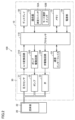
- 1 is a block diagram showing an example of a hardware configuration of a blood pressure monitor according to the first embodiment.
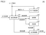
- FIG. 1 is a block diagram showing a functional configuration of a blood pressure monitor according to Embodiment 1.
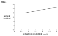
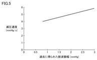
- FIG. 3 is a diagram showing the relationship between pulse wave amplitude and decompression rate during the pressurization process. It is a figure which shows the relationship between the pulse wave amplitude and decompression speed obtained in the past.
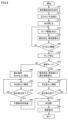
- 3 is a flowchart illustrating an example of a processing procedure of the blood pressure monitor according to the first embodiment.
- 7 is a flowchart showing another example of the processing procedure of the blood pressure monitor according to the first embodiment.
- FIG. 7 is a flowchart showing still another example of the processing procedure of the blood pressure monitor according to the first embodiment.
- FIG. 3 is a diagram for explaining the relationship between the time required to reach a predetermined pressure and the pressure reduction speed.
- FIG. 3 is a diagram for explaining the relationship between the time required to reach a predetermined pressure, the decompression speed, and the cuff size.
- 7 is a flowchart illustrating an example of a processing procedure of the blood pressure monitor according to the second embodiment.
- 7 is a flowchart showing another example of the processing procedure of the blood pressure monitor according to the second embodiment.
- FIG. 3 is a block diagram showing the functional configuration of a blood pressure monitor according to a third embodiment.
- 12 is a flowchart illustrating an example of a processing procedure of the blood pressure monitor according to the third embodiment.
- FIG. 1 is a diagram showing a blood pressure monitor 100 according to this embodiment.
- sphygmomanometer 100 is an upper arm sphygmomanometer that measures the blood pressure of a user (i.e., a subject) by compressing the measurement site of the user (i.e., the subject) with a cuff.
- the blood pressure monitor 100 measures blood pressure using an oscillometric method.
- the blood pressure monitor 100 has a main body and a cuff (arm cuff) as main components.
- the blood pressure monitor 100 may be a wrist-type blood pressure monitor in which a main body and a cuff (arm cuff) are integrated. The processing details will be explained below with reference to FIG.
- FIG. 1 it is assumed that a user measures his or her own blood pressure using a blood pressure monitor 100.
- the blood pressure monitor 100 measures the user's blood pressure using a reduced pressure measurement method that measures the blood pressure during the process of reducing the cuff pressure, which indicates the internal pressure of the cuff attached to the user's measurement target site (eg, arm).
- the blood pressure monitor 100 starts pressurizing the cuff according to the user's blood pressure measurement instruction (corresponding to (1) in FIG. 1).
- the sphygmomanometer 100 estimates systolic blood pressure (systolic blood pressure) and diastolic blood pressure (diastolic blood pressure) based on the detected pulse wave signal during the cuff pressure increase process (corresponding to (2) in FIG. 1). Estimation of systolic blood pressure and diastolic blood pressure is performed by a known method. For example, the sphygmomanometer 100 estimates systolic blood pressure and diastolic blood pressure from a pulse wave envelope that indicates a pattern of amplitude changes in a pulse wave signal that changes during the process of increasing cuff pressure.
- the estimated systolic blood pressure will be referred to as "estimated systolic blood pressure”
- the estimated diastolic blood pressure will also be referred to as “estimated diastolic blood pressure.”
- the blood pressure monitor 100 selects either the normal measurement mode (hereinafter also simply referred to as "normal mode") or the arrhythmia determination mode (corresponding to (3) in FIG. 1).
- the arrhythmia determination mode is a mode in which arrhythmia determination is performed along with blood pressure measurement based on a pulse wave signal during a cuff pressure reduction process that follows a pressurization process.
- the normal mode is a mode in which only blood pressure measurement is performed based on the pulse wave signal during the pressure reduction process, and arrhythmia determination is not performed.
- the arrhythmia determination mode has been selected.
- the blood pressure monitor 100 sets the cuff pressure reduction rate in the pressure reduction process during the arrhythmia determination mode (corresponding to (4) in FIG. 1).
- the pressure reduction rate is set so that a predetermined pulse rate is obtained between the estimated pulse pressure, which is the difference between the estimated systolic blood pressure and the estimated diastolic blood pressure.
- the pressure reduction speed in the arrhythmia determination mode is set to be slower than the pressure reduction speed in the normal mode. It is known that when the pressure reduction rate is slowed down, the amplitude of the pulse wave signal obtained during the pressure reduction process (hereinafter referred to as "pulse wave amplitude") increases. Therefore, the pulse wave amplitude obtained during the pressure reduction process in the arrhythmia determination mode is larger than the pulse wave amplitude obtained during the pressure reduction process in the normal mode.
- the sphygmomanometer 100 calculates the user's blood pressure value based on the pulse wave signal obtained during the pressure reduction process, and determines whether an arrhythmia has occurred (corresponding to (5) in FIG. 1). In this case, the blood pressure monitor 100 displays the user's blood pressure value and arrhythmia determination result on the display.
- the pulse wave amplitude obtained in the arrhythmia detection mode is larger than the pulse wave amplitude obtained in the normal mode, so a more accurate pulse wave interval pattern can be obtained in the arrhythmia detection mode. It will be done. Therefore, the blood pressure monitor 100 can perform arrhythmia determination with higher accuracy.
- the sphygmomanometer 100 creates a pulse wave envelope based on the amplitude of the acquired pulse wave signal and the cuff pressure, and calculates the blood pressure based on the pulse wave envelope.
- the blood pressure monitor 100 performs processing such as correction and smoothing of the pulse wave envelope so that blood pressure can be calculated even when the acquired pulse wave signal is too small to be recognized as a pulse wave. Therefore, in the normal mode where the pressure reduction speed is fast, the blood pressure monitor 100 can calculate blood pressure in a short measurement time. Therefore, blood pressure measurement is quickly performed for users who do not want arrhythmia determination.
- arrhythmia can be accurately determined by acquiring a large amplitude pulse wave signal during the pressure reduction process of blood pressure measurement.
- FIG. 2 is a block diagram showing an example of the hardware configuration of blood pressure monitor 100 according to the first embodiment.
- blood pressure monitor 100 includes a main body 10 and a cuff 20 as main components.
- a fluid bag 22 is enclosed in the cuff 20 .
- the main body 10 includes a processor 110, an air system component 30 for blood pressure measurement, an A/D conversion circuit 310, a pump drive circuit 320, a valve drive circuit 330, a display 50, a memory 51, and an operation section 52. , a communication interface 53, and a power supply unit 54.
- the processor 110 is an arithmetic processing unit such as a CPU (Central Processing Unit) or an MPU (Multi Processing Unit).
- the processor 110 reads and executes a program stored in the memory 51, thereby realizing each of the processes (steps) of the blood pressure monitor 100, which will be described later.
- the processor 110 controls driving the pump 32 and the valve 33 in response to an operation signal from the operation unit 52.
- the processor 110 calculates a blood pressure value using an algorithm for calculating blood pressure using an oscillometric method, and displays the value on the display 50.
- the memory 51 is realized by RAM (Random Access Memory), ROM (Read-Only Memory), flash memory, or the like.
- the memory 51 stores programs for controlling the blood pressure monitor 100, data used for controlling the blood pressure monitor 100, setting data for setting various functions of the blood pressure monitor 100, data on blood pressure measurement results, and pulse rate. Memorize the number, pulse wave interval, etc. Further, the memory 51 is used as a work memory etc. when a program is executed.
- the air system component 30 supplies or discharges air to the fluid bag 22 contained in the cuff 20 through air piping.
- the air system component 30 includes a pressure sensor 31 for detecting the pressure within the fluid bag 22, and a pump 32 and a valve 33 as an expansion and contraction mechanism for expanding and contracting the fluid bag 22.
- the pressure sensor 31 detects the pressure within the fluid bag 22 (cuff pressure) and outputs a signal (cuff pressure signal) corresponding to the detected pressure to the A/D conversion circuit 310.
- the pressure sensor 31 is, for example, a piezoresistive pressure sensor, and is connected to the pump 32, the valve 33, and the fluid bag 22 included in the cuff 20 via air piping.
- the pump 32 supplies air as a fluid to the fluid bag 22 through the air piping in order to increase the cuff pressure.
- the valve 33 is opened and closed in order to control the cuff pressure by discharging the air in the fluid bag 22 through the air piping or filling the fluid bag 22 with air.
- the A/D conversion circuit 310 converts the output value of the pressure sensor 31 (for example, a voltage value according to a change in electrical resistance due to the piezoresistive effect) from an analog signal to a digital signal and outputs the digital signal to the processor 110.
- Processor 110 obtains a signal representing cuff pressure according to the output value of A/D conversion circuit 310.
- Pump drive circuit 320 controls the drive of pump 32 based on a control signal given from processor 110.
- Valve drive circuit 330 controls opening and closing of valve 33 based on a control signal given from processor 110.
- a cuff is wrapped around the part to be measured (wrist, arm, etc.) of the subject in advance, and at the time of measurement, the pump 32 and valve 33 are controlled to increase the cuff pressure to a level higher than the estimated systolic blood pressure. , and then gradually decompress.
- the cuff pressure is detected by a pressure sensor, and fluctuations in arterial volume occurring in the artery at the measurement site are extracted as a pulse wave signal.
- Systolic blood pressure and diastolic blood pressure are calculated based on changes in the amplitude of the pulse wave signal (mainly rise and fall) accompanying changes in cuff pressure at that time.
- the operation unit 52 inputs an operation signal to the processor according to a user's instruction.
- the operation unit 52 includes a measurement switch 52A for receiving a blood pressure measurement instruction from the user, and a mode selection switch 52B for selecting a measurement mode.
- the measurement switch 52A When the measurement switch 52A is pressed, the part to be measured is temporarily compressed by the cuff 20, and blood pressure measurement is performed using the oscillometric method. If the measurement switch 52A is pressed again during blood pressure measurement, blood pressure measurement is stopped.
- the measurement mode is switched. For example, if the mode selection switch 52B is pressed when the current measurement mode is set to the normal mode, the measurement mode is switched to the arrhythmia determination mode.
- the display 50 displays various information including blood pressure measurement results and the like based on control signals from the processor 110.
- the communication interface 53 exchanges various information with external devices.
- the power supply unit 54 supplies power to the processor 110 and each piece of hardware.
- FIG. 3 is a block diagram showing the functional configuration of blood pressure monitor 100 according to the first embodiment.
- blood pressure monitor 100 includes a mode setting section 210, a blood pressure measurement section 220, a determination section 230, and an output control section 240 as main functional components.
- Each of these functions is realized, for example, by the processor 110 of the blood pressure monitor 100 executing a program stored in the memory 51. Note that some or all of these functions may be configured to be implemented by hardware.
- Blood pressure monitor 100 further includes a storage unit 250.
- the storage unit 250 is realized by the memory 51.
- the mode setting unit 210 sets either an arrhythmia determination mode that determines whether or not the user has an arrhythmia, or a normal mode that does not perform an arrhythmia determination.
- the mode setting section 210 sets either the arrhythmia determination mode or the normal mode in accordance with a mode selection instruction from the user via the operation section 52 (for example, the mode selection switch 52B).
- the mode setting unit 210 may be configured to automatically set one of the modes according to a predetermined schedule. For example, when blood pressure measurement is started during time period H of the day (for example, blood pressure measurement is started by pressing the measurement switch 52A), the arrhythmia determination mode is automatically set. On the other hand, when blood pressure measurement is performed during a time period other than time period H during the day, the normal mode is automatically set.
- the blood pressure measurement unit 220 controls the cuff pressure in accordance with a measurement start instruction from the user via the operation unit 52 (eg, measurement switch 52A). Specifically, the blood pressure measurement unit 220 drives the pump 32 via the pump drive circuit 320 and controls the valve 33 via the valve drive circuit 330. Valve 33 is opened and closed to vent or enclose air in fluid bladder 22 to control cuff pressure.
- the blood pressure measurement unit 220 receives the cuff pressure signal detected by the pressure sensor 31 and extracts a pulse wave signal representing the pulse wave of the measurement site superimposed on the cuff pressure signal. That is, the blood pressure measurement unit 220 detects a pulse wave, which is a pressure component superimposed on the cuff pressure signal in synchronization with the user's heartbeat, from the cuff pressure signal.
- the blood pressure measurement unit 220 calculates the user's blood pressure information based on the cuff pressure signal and the pulse wave signal superimposed on the cuff pressure signal. Specifically, the blood pressure measurement unit 220 measures the user's blood pressure according to the oscillometric method. In this embodiment, the user's blood pressure is calculated based on the pulse wave signal during the depressurization process in which the cuff pressure is decreased after the cuff pressure is increased to a pressure higher than a specified pressure (for example, estimated systolic blood pressure). A reduced pressure measurement method is adopted. Typically, blood pressure measurement unit 220 calculates systolic blood pressure, diastolic blood pressure, pulse rate, and pulse pressure. The storage unit 250 stores information obtained during blood pressure measurement (eg, pulse wave signal, systolic blood pressure, diastolic blood pressure, pulse rate, pulse pressure, etc.).
- the blood pressure measurement unit 220 sets the cuff pressure reduction rate in the pressure reduction process. Specifically, the blood pressure measurement unit 220 makes the cuff pressure reduction speed G1 when the arrhythmia determination mode is set slower than the cuff pressure reduction speed G2 when the normal mode is set.
- the blood pressure measuring unit 220 calculates an estimated systolic blood pressure and an estimated diastolic blood pressure based on a pulse wave signal during the pressurization process, and calculates an estimated pulse pressure that is the difference between the estimated systolic blood pressure and the estimated diastolic blood pressure. and a predetermined pulse rate (for example, 8 beats) necessary for measuring the user's blood pressure, the decompression rate G2 is set.
- the blood pressure monitor 100 sets the pressure reduction rate G2 so that the pulse rate occurring between the estimated pulse pressures is equal to or higher than a predetermined pulse rate.
- the blood pressure measuring unit 220 sets the pressure reduction speed G1 to a predetermined speed (for example, 4 mmHg/s). This speed (for example, 4 mmHg/s) is sufficiently slower than the decompression speed G2 calculated by the above method.
- the blood pressure measurement unit 220 sets the decompression rate G1 based on the pulse wave amplitude during the pressurization process.
- the blood pressure measurement unit 220 sets the pressure reduction speed G1 to be slower as the pulse wave amplitude is smaller.
- FIG. 4 is a diagram showing the relationship between pulse wave amplitude and decompression rate during the pressurization process.
- the vertical axis of the graph in FIG. 4 indicates the decompression rate G1
- the horizontal axis indicates the maximum pulse wave amplitude obtained during the pressurization process. It can be seen that the smaller the maximum pulse wave amplitude during the pressurization process, the slower the decompression speed G1 becomes. This is for the purpose of highly accurate arrhythmia determination by obtaining a pulse wave amplitude having a certain magnitude or more during the pressure reduction process.
- the pulse wave amplitude during the pressurization process is large, the pulse wave amplitude during the pressure reduction process is also large. Therefore, when the pulse wave amplitude during the pressurization process is small, the pressure reduction rate is slowed so that the pulse wave amplitude obtained during the pressure reduction process becomes large.
- the pulse wave amplitude during the pressurization process is sufficiently large, it is thought that a large pulse wave amplitude can also be obtained during the pressure reduction process, so the pressure reduction rate is increased. In this case, the measurement time becomes shorter.
- the pressure reduction rate G1 is set to a pressure reduction rate necessary to obtain a pulse wave amplitude of a certain magnitude or more. Thereby, a more appropriate decompression rate can be set for the user, and highly accurate arrhythmia determination can be achieved with an appropriate measurement time.
- blood pressure measurement section 220 sets pressure reduction rate G1 based on the amplitude of the past pulse wave signal (i.e., pulse wave amplitude) stored in storage section 250.
- FIG. 5 is a diagram showing the relationship between pulse wave amplitude and decompression speed obtained in the past.
- the vertical axis of the graph in FIG. 5 shows the decompression rate G1
- the horizontal axis shows the pulse wave amplitude (hereinafter referred to as "pulse wave amplitude Am ). It can be seen that the smaller the pulse wave amplitude Am, the slower the decompression speed G1. This is for the purpose of highly accurate arrhythmia determination by obtaining a pulse wave amplitude having a certain magnitude or more during the pressure reduction process.
- the pulse wave amplitude Am obtained in the past is small, it is estimated that the pulse wave amplitude during the pressure reduction process during the current blood pressure measurement is also small. Therefore, if the pulse wave amplitude Am obtained in the past is small, the pressure reduction speed is slowed so that the pulse wave amplitude obtained in the current pressure reduction process becomes large. On the other hand, if the pulse wave amplitude Am obtained in the past is sufficiently large, it is considered that a large pulse wave amplitude will be obtained in the current pressure reduction process, so the pressure reduction speed is increased. In this case, the measurement time becomes shorter. In this way, as in the case of FIG.
- the pressure reduction rate G1 is set to the pressure reduction rate necessary to obtain a pulse wave amplitude of a certain magnitude or more. Even in this case, a more appropriate decompression rate can be set for the user, and highly accurate arrhythmia determination can be achieved with an appropriate measurement time.
- the storage unit 250 stores pulse wave amplitudes during a predetermined period in the past.
- the storage unit 250 stores a pulse wave signal during a pressurization process or a depressurization process when the user's blood pressure is measured.
- the blood pressure measuring unit 220 calculates the average value of the maximum pulse wave amplitude during the pressurization process during the most recent multiple (for example, three) blood pressure measurements based on the data stored in the storage unit 250. Then, the average value is set as the pulse wave amplitude Am.
- the blood pressure measurement unit 220 extracts data from past blood pressure measurements during the same time period as the current blood pressure measurement (for example, morning, noon, night, etc.), and The maximum pulse wave amplitude is set as the pulse wave amplitude Am. As yet another example, the blood pressure measurement unit 220 sets the maximum pulse wave amplitude in the pressurization process of multiple blood pressure measurements within a predetermined period (for example, one day) as the pulse wave amplitude Am.
- the determining unit 230 determines whether or not the user's arrhythmia has occurred based on the pulse wave signal during the pressure reduction process.
- a known method is used to determine the arrhythmia. For example, the determining unit 230 determines whether or not an arrhythmia has occurred based on the interval between occurrences of a plurality of pulse waves (ie, pulse wave interval) obtained from the pulse wave signal.
- the output control unit 240 displays the measurement results of the blood pressure measurement unit 220, the determination results of the determination unit 230, etc. on the display 50. Note that the output control unit 240 may transmit the measurement results and determination results to an external device via the communication interface 53, or may be configured to output audio via a speaker (not shown).
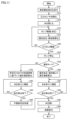
- FIG. 6 is a flowchart illustrating an example of the processing procedure of the blood pressure monitor 100 according to the first embodiment. It is assumed that the user is wearing the cuff 20 of the blood pressure monitor 100 at the start of the process. In FIG. 6, it is assumed that the normal mode or the arrhythmia determination mode is set as the measurement mode.
- processor 110 of blood pressure monitor 100 receives an instruction to start blood pressure measurement from the user via measurement switch 52A of operation unit 52 (step S10).
- the processor 110 initializes the pressure sensor 31 (step S12). Specifically, the processor 110 initializes the processing memory area, turns off (stops) the pump 32, and adjusts the pressure sensor 31 to 0 mmHg (sets the atmospheric pressure to 0 mmHg) with the valve 33 open. Do the following.
- the processor 110 closes the valve 33 via the valve drive circuit 330 (step S14), turns on (starts) the pump 32 via the pump drive circuit 320, and starts pressurizing the cuff 20 (fluid bag 22). (Step S16). Typically, the processor 110 controls the pump drive circuit 320 for pressurization, thereby driving the pump 32 so that the rate of cuff pressure increase is constant.
- Processor 110 extracts a pulse wave signal from the cuff pressure signal detected by pressure sensor 31, and calculates estimated systolic blood pressure, estimated diastolic blood pressure, and pulse rate based on the pulse wave signal obtained during the pressurization process. (Step S18).
- the processor 110 determines whether the cuff pressure has reached the threshold Th or more (step S20).
- the threshold Th is set to a value higher than the estimated systolic blood pressure by a fixed value (for example, 40 mmHg).
- step S20 If the cuff pressure is less than the threshold Th (NO in step S20), the processor 110 returns to step S16. If the cuff pressure is equal to or higher than the threshold Th (YES in step S20), the processor 110 stops the pump 32 (step S22), and determines whether the currently set measurement mode is the normal mode ( Step S24).
- the processor 110 calculates the pressure reduction rate G2 based on the estimated pulse pressure, which is the difference between the estimated systolic blood pressure and the estimated diastolic blood pressure, and the pulse rate (step S26).
- the processor 110 controls the valve 33 to gradually open according to the pressure reduction rate G2 (step S28). As a result, the pressurization process shifts to the depressurization process, and the cuff pressure gradually decreases according to the depressurization rate G2.
- the processor 110 extracts a pulse wave signal from the cuff pressure signal detected by the pressure sensor 31, attempts to calculate the systolic blood pressure and the diastolic blood pressure based on the pulse wave signal, and calculates the blood pressure. is completed (step S30). If blood pressure calculation cannot be completed yet due to insufficient data (NO in step S30), processor 110 returns to step S28. When blood pressure calculation is completed (YES in step S30), processor 110 controls to fully open valve 33 (step S32) and rapidly exhaust the air in cuff 20. Processor 110 displays the blood pressure value (measurement result) measured in step S30 on display 50 (step S34).
- the processor 110 sets the pressure reduction speed G1 to a predetermined speed (for example, 4 mmHg/s) (step S40). It is assumed that the predetermined speed is sufficiently slower than the pressure reduction speed G2.
- the processor 110 controls the valve 33 to gradually open according to the pressure reduction rate G1 (step S42). Thereby, the pressurization process shifts to the depressurization process, and the cuff pressure gradually decreases according to the depressurization rate G1.
- the processor 110 extracts a pulse wave signal from the cuff pressure signal, attempts to calculate systolic blood pressure and diastolic blood pressure based on the pulse wave signal, and determines whether blood pressure calculation is complete. (Step S44). If blood pressure calculation cannot be completed (NO in step S44), processor 110 returns to step S42. When blood pressure calculation is completed (YES in step S44), processor 110 executes arrhythmia determination processing (step S46). Specifically, the processor 110 determines whether an arrhythmia has occurred based on the pulse wave interval obtained from the pulse wave signal during the pressure reduction process.
- step S34 blood pressure measurement results and arrhythmia determination results are displayed as measurement results.
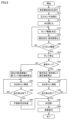
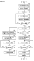
- FIG. 7 is a flowchart showing another example of the processing procedure of the blood pressure monitor 100 according to the first embodiment.
- the flowchart in FIG. 7 corresponds to the flowchart in FIG. 6 in which step S40 is replaced with step S50. Therefore, detailed description of processes other than step S50 will not be repeated.
- processor 110 calculates the decompression rate G1 based on the amplitude of the pulse wave signal during the pressurization process (i.e., pulse wave amplitude). For example, the processor 110 calculates the decompression rate G1 according to the graph of FIG.
- FIG. 8 is a flowchart showing still another example of the processing procedure of the blood pressure monitor 100 according to the first embodiment.
- the flowchart in FIG. 8 corresponds to the flowchart in FIG. 6 in which step S40 is replaced with step S60. Therefore, detailed description of processes other than step S60 will not be repeated.
- processor 110 calculates the decompression rate G1 based on the pulse wave amplitude obtained in the past. For example, the processor 110 calculates the decompression rate G1 according to the graph of FIG.
- the size of the cuff is determined according to the circumference of the part to be measured, and the longer the circumference of the part to be measured, the larger the size of the cuff becomes.
- the size of the cuff increases, the capacity of the fluid bag increases, so the ratio of the change in volume of the fluid bag to the change in volume of the artery becomes smaller.
- the change in cuff pressure that is, the amplitude of the pulse wave signal (ie, pulse wave amplitude) becomes smaller.
- Blood pressure measuring section 220 according to the second embodiment further has the following functions in addition to the functions described in FIG. 3.
- the blood pressure measurement unit 220 pressurizes the cuff by driving the pump 32 so that the discharge flow rate is constant per unit time. Based on the cuff pressure signal detected by the pressure sensor 31, the blood pressure measurement unit 220 measures the time T required for the cuff pressure to reach a predetermined pressure in the pressurization process. The arrival time T varies depending on the capacity (size) of the cuff. For example, the blood pressure measurement unit 220 measures the time T required for the cuff pressure to reach from "0 mmHg" to "30 mmHg.” The blood pressure measurement unit 220 sets the pressure reduction speed G1 to be slower as the arrival time T is longer.
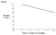
- FIG. 9 is a diagram for explaining the relationship between the time required to reach a predetermined pressure and the pressure reduction rate.
- the vertical axis of the graph in FIG. 9 shows the pressure reduction rate G1
- the horizontal axis shows the arrival time T until the cuff pressure reaches "30 mmHg" from "0 mmHg".
- the longer the arrival time T the larger the cuff capacity (i.e., the cuff size). do.
- the larger the cuff size the smaller the pulse wave amplitude. Therefore, the longer the arrival time T (that is, the larger the size of the cuff), the slower the decompression rate G1, the larger the pulse wave amplitude obtained during the decompression process. This enables highly accurate arrhythmia determination.
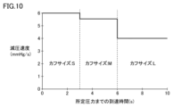
- FIG. 10 is a diagram for explaining the relationship between the time taken to reach a predetermined pressure, the decompression rate, and the cuff size.
- the vertical axis of the graph in FIG. 10 is the decompression rate G1
- the horizontal axis is the arrival time T.
- the blood pressure measurement unit 220 estimates the cuff size as "Small” when the arrival time T is less than 3 seconds, and estimates the cuff size as “Medium” when the arrival time T is 3 seconds or more and less than 6 seconds. If the arrival time T is 6 seconds or more, the cuff size is estimated to be "Large”. That is, the blood pressure measurement unit 220 estimates that the longer the arrival time T, the larger the cuff size.
- the blood pressure measuring unit 220 sets the decompression rate G1 to 6 mmHg/s, and when the cuff size is estimated to be “Medium”, the decompression rate G1 is set to 5.5 mmHg/s. /s and the cuff size is estimated to be “Large”, the decompression rate G1 is set to 4 mmHg/s. That is, the blood pressure measurement unit 220 sets the pressure reduction speed G1 to be slower as the cuff size becomes larger.
- FIG. 11 is a flowchart showing an example of the processing procedure of the blood pressure monitor 100 according to the second embodiment.
- the flowchart in FIG. 11 corresponds to the flowchart in FIG. 6 in which step S40 is replaced with step S70. Therefore, detailed description of the processes other than step S70 will not be repeated.
- the processor 110 controls the pump drive circuit 320 for pressurization, thereby driving the pump 32 to have a constant discharge flow rate per unit time.
- step S70 processor 110 calculates the decompression rate G1 based on the arrival time T until the cuff pressure reaches a predetermined pressure in the pressurization process. For example, the processor 110 calculates the decompression rate G1 according to the graph of FIG.
- FIG. 12 is a flowchart showing another example of the processing procedure of the blood pressure monitor 100 according to the second embodiment.
- the flowchart in FIG. 12 corresponds to the flowchart in FIG. 6 in which step S40 is replaced with steps S80 and S82. Therefore, detailed description of processes other than steps S80 and S82 will not be repeated.
- the processor 110 controls the pump drive circuit 320 for pressurization, thereby driving the pump 32 to have a constant discharge flow rate per unit time.
- processor 110 estimates the cuff size based on the arrival time T (step S80), and calculates the decompression rate G1 based on the estimated cuff size (step S82). Specifically, the processor 110 estimates the cuff size and calculates the decompression rate G1 according to the graph in FIG. 10.
- Embodiment 3 a method of setting the decompression speed G1 by focusing on the degree of tightening of the cuff will be described.
- the fluid bag will need to inflate more to fill the gap between the living body and the cuff. Therefore, when the cuff is loosely wound, the capacity of the fluid bag becomes larger than when the cuff is tightly wound, and as a result, the amplitude of the obtained pulse wave signal becomes smaller.
- a method for setting the pressure reduction speed G1 according to the third embodiment will be explained.
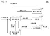
- FIG. 13 is a block diagram showing the functional configuration of blood pressure monitor 100 according to the third embodiment.
- blood pressure monitor 100 includes a mode setting section 210, a blood pressure measurement section 220, a determination section 230, an output control section 240, and a wrapping strength detection section 260.
- Each of these functions is realized, for example, by the processor 110 of the blood pressure monitor 100 executing a program stored in the memory 51.
- the functions of the mode setting section 210, the determination section 230, and the output control section 240 are the same as those described with reference to FIG.
- the wrapping strength detection unit 260 detects the wrapping strength of the cuff 20 around the measurement target site based on the cuff pressure and the volume change of the cuff 20 during the pressurization process.
- the winding strength detection method is realized by a known method.
- the winding strength detection section 260 has the same function as the winding strength detection section shown in Japanese Patent No. 5408142.
- the wrapping strength detection unit 260 detects a change in cuff pressure from pressure P1 to pressure P2 during a pressurization process in which the cuff is pressurized by driving the pump 32 so as to maintain a constant discharge flow rate. Based on the pressure-volume change relationship shown by the volume change of the cuff 20 detected as the cuff pressure changes from pressure P2 to pressure P3, the cuff pressure changes from pressure P1 to pressure P2. The result of comparing the value of the volume change of the cuff 20 detected as the cuff pressure changes from pressure P2 to the value of the volume change of the cuff 20 detected as the cuff pressure changes from pressure P2 to P3. The wrapping strength of the cuff 20 is detected from .
- the pressures P1, P2, and P3 are cuff pressures that are determined in advance through experiments and the like and are suitable for detecting the wrapping strength of the cuff.
- the times when the cuff pressure reaches pressures P1 to P3 are defined as times V1 to V3, respectively.
- the wrapping strength detection unit 260 detects a change ⁇ P12, which is the difference between the pressure P1 and the pressure P2, and a time ⁇ V12, which indicates the time required for the cuff pressure to change by ⁇ P12 (i.e., time V2 - V1). calculate.
- the time ⁇ V12 is proportional to the change in fluid volume within the cuff when changing from pressure P1 to pressure P2.
- the wrapping strength detection unit 260 calculates a change ⁇ P23, which is the difference between the pressure P2 and the pressure P3, and a time ⁇ V23, which indicates the time required for the cuff pressure to change by ⁇ P23 (ie, time V3 ⁇ V2).
- the time ⁇ V23 is proportional to the change in fluid volume within the cuff when changing from pressure P2 to pressure P3.
- the winding strength detection unit 260 calculates pressure volume change indexes ⁇ P12/ ⁇ V12 and ⁇ P23/ ⁇ V23, and compares the two calculated values. Based on this comparison result, the winding strength detection section 260 detects the winding strength.
- “Loose wrapping” is a wrapping state in which the cuff 20 is loosely wrapped around the area to be measured and the pressurization of the area to be measured is lower than the appropriate level.
- “Tight wrapping” is a wrapping state in which the cuff 20 is appropriately wrapped around the region to be measured and the pressurization of the region to be measured is at an appropriate level.
- “Tight wrapping” is a wrapping state in which the cuff 20 is tightly wrapped around the region to be measured and the pressurization of the region to be measured is higher than the appropriate level.
- the blood pressure measurement unit 220 sets the pressure reduction speed G1 to be slower as the wrapping strength detected by the wrapping strength detection unit 260 is smaller.
- the decompression speed G1 when the winding strength is “loose winding” is “G1a”
- the decompression speed G1 when the winding strength is “tight winding” is “G1b”
- the winding strength is "tight winding”.
- the decompression speed G1 in the case of "Volume” is defined as "G1c”.
- the pressure reduction speed G1a is the slowest
- the pressure reduction speed G1c is the fastest
- the pressure reduction speed G1b is in between (that is, G1a ⁇ G1b ⁇ G1c).
- FIG. 14 is a flowchart illustrating an example of the processing procedure of the blood pressure monitor 100 according to the third embodiment.
- the flowchart of FIG. 14 corresponds to the flowchart of FIG. 6 in which step S40 is replaced with steps S90, S92, S94, and S96. Therefore, detailed description of processes other than steps S90, S92, S94, and S96 will not be repeated.
- the processor 110 controls the pump drive circuit 320 for pressurization, thereby driving the pump 32 to have a constant discharge flow rate per unit time.
- processor 110 detects the wrapping strength of cuff 20 around the region to be measured (step S90).
- the processor 110 determines whether the detected winding strength is equal to or higher than "perfect winding" (that is, "perfect winding” or “tight winding") (step S92). If the winding strength is equal to or higher than "perfect winding” (YES in step S92), the processor 110 reduces the pressure based on the estimated pulse pressure, which is the difference between the estimated systolic blood pressure and the estimated diastolic blood pressure, and the pulse rate.
- the speed G1 is calculated (step S96).
- the processor 110 sets the decompression speed G1 to a predetermined speed (for example, 4 mmHg/s) (step S94).
- the flowchart in FIG. 14 describes a configuration in which the decompression rate G1 is calculated based on the estimated pulse pressure and pulse rate using the same calculation method as in the normal mode when the winding strength is "perfect winding" or higher.
- the configuration is not limited to this.
- the pressure reduction speed G1 may be set to the above-mentioned pressure reduction speeds G1a to G1c depending on the winding strength ("loose winding", “tight winding", or "tight winding").
- this embodiment includes the following disclosures.
- a sphygmomanometer (100) that measures blood pressure by compressing a measurement target area of a user with a cuff (20), which includes a pressurization process in which the cuff pressure indicating the internal pressure of the cuff is increased to a pressure greater than a specified pressure. Thereafter, a blood pressure measurement unit (220) measures the blood pressure of the user based on a pulse wave signal during the decompression process to reduce the cuff pressure, and a blood pressure measurement unit (220) that measures the blood pressure of the user based on the pulse wave signal during the decompression process, and detects whether arrhythmia has occurred in the user based on the pulse wave signal during the decompression process.
- the blood pressure measurement unit may set a first rate of decrease in the cuff pressure when the first mode is set to be higher than a second rate of decrease in the cuff pressure when the second mode is set. Slow down, blood pressure monitor.
- the blood pressure measurement unit further includes a storage unit (250) that stores a pulse wave signal in the pressurization process or the pressure reduction process when the blood pressure of the user is measured by the blood pressure measurement unit, and the blood pressure measurement unit stores the pulse wave signal in the storage unit.
- the blood pressure measurement unit estimates the size of the cuff based on the time it takes for the cuff pressure to reach a predetermined pressure in the pressurization process, and the larger the estimated cuff size, the higher the first decompression rate.
- the blood pressure measurement unit further includes a wrapping strength detection unit (260) that detects the wrapping strength of the cuff around the measurement target site based on the cuff pressure and the volume change of the cuff in the pressurization process.
- a wrapping strength detection unit 260
- the blood pressure measurement unit determines the second pressure reduction rate based on an estimated pulse pressure that is a difference between an estimated systolic blood pressure and an estimated diastolic blood pressure, and a predetermined pulse rate necessary for measuring the user's blood pressure.
- the blood pressure monitor according to any one of configurations 1 to 7.
- measuring the blood pressure of the user based on a pulse wave signal during the pressure reduction process of reducing the cuff pressure and determining whether arrhythmia has occurred in the user based on the pulse wave signal during the pressure reduction process. and setting either a first mode in which the arrhythmia determination is performed or a second mode in which the arrhythmia determination is not performed, wherein the first mode is set.
- the first rate of reduction of the cuff pressure when the mode is set is slower than the second rate of reduction of the cuff pressure when the second mode is set.
Landscapes
- Health & Medical Sciences (AREA)
- Life Sciences & Earth Sciences (AREA)
- Cardiology (AREA)
- Vascular Medicine (AREA)
- Engineering & Computer Science (AREA)
- Biomedical Technology (AREA)
- Veterinary Medicine (AREA)
- Biophysics (AREA)
- Pathology (AREA)
- Physiology (AREA)
- Physics & Mathematics (AREA)
- Heart & Thoracic Surgery (AREA)
- Medical Informatics (AREA)
- Molecular Biology (AREA)
- Surgery (AREA)
- Animal Behavior & Ethology (AREA)
- General Health & Medical Sciences (AREA)
- Public Health (AREA)
- Ophthalmology & Optometry (AREA)
- Dentistry (AREA)
- Signal Processing (AREA)
- Measuring Pulse, Heart Rate, Blood Pressure Or Blood Flow (AREA)
Priority Applications (3)
| Application Number | Priority Date | Filing Date | Title |
|---|---|---|---|
| CN202380047464.5A CN119365123A (zh) | 2022-09-16 | 2023-05-19 | 血压计和血压测定方法 |
| DE112023003863.5T DE112023003863T5 (de) | 2022-09-16 | 2023-05-19 | Blutdruckmessgerät und verfahren zum messen von blutdruck |
| US18/990,636 US20250120606A1 (en) | 2022-09-16 | 2024-12-20 | Sphygmomanometer and method for measuring blood pressure |
Applications Claiming Priority (2)
| Application Number | Priority Date | Filing Date | Title |
|---|---|---|---|
| JP2022-148239 | 2022-09-16 | ||
| JP2022148239A JP7823532B2 (ja) | 2022-09-16 | 2022-09-16 | 血圧計、および血圧測定方法 |
Related Child Applications (1)
| Application Number | Title | Priority Date | Filing Date |
|---|---|---|---|
| US18/990,636 Continuation US20250120606A1 (en) | 2022-09-16 | 2024-12-20 | Sphygmomanometer and method for measuring blood pressure |
Publications (1)
| Publication Number | Publication Date |
|---|---|
| WO2024057618A1 true WO2024057618A1 (ja) | 2024-03-21 |
Family
ID=90274498
Family Applications (1)
| Application Number | Title | Priority Date | Filing Date |
|---|---|---|---|
| PCT/JP2023/018718 Ceased WO2024057618A1 (ja) | 2022-09-16 | 2023-05-19 | 血圧計、および血圧測定方法 |
Country Status (5)
| Country | Link |
|---|---|
| US (1) | US20250120606A1 (cg-RX-API-DMAC7.html) |
| JP (1) | JP7823532B2 (cg-RX-API-DMAC7.html) |
| CN (1) | CN119365123A (cg-RX-API-DMAC7.html) |
| DE (1) | DE112023003863T5 (cg-RX-API-DMAC7.html) |
| WO (1) | WO2024057618A1 (cg-RX-API-DMAC7.html) |
Cited By (1)
| Publication number | Priority date | Publication date | Assignee | Title |
|---|---|---|---|---|
| CN119867687A (zh) * | 2024-12-31 | 2025-04-25 | 江苏鱼跃医疗设备股份有限公司 | 基于单次测量多次加压的心房颤动检测方法、装置、介质 |
Citations (4)
| Publication number | Priority date | Publication date | Assignee | Title |
|---|---|---|---|---|
| JPH05200005A (ja) * | 1992-01-28 | 1993-08-10 | Omron Corp | 電子血圧計 |
| JP2001070263A (ja) * | 1999-09-08 | 2001-03-21 | Omron Corp | 電子血圧計 |
| JP2015070969A (ja) * | 2013-10-03 | 2015-04-16 | シチズンホールディングス株式会社 | 血圧計 |
| JP2022099105A (ja) * | 2020-12-22 | 2022-07-04 | オムロンヘルスケア株式会社 | 電子血圧計、および、電子血圧計における心房細動判定方法 |
Family Cites Families (2)
| Publication number | Priority date | Publication date | Assignee | Title |
|---|---|---|---|---|
| US4587974A (en) * | 1984-11-13 | 1986-05-13 | Norse Instruments | Linear pressurizing and depressurizing device |
| JPH031837A (ja) * | 1989-05-30 | 1991-01-08 | Omron Corp | 電子血圧計 |
-
2022
- 2022-09-16 JP JP2022148239A patent/JP7823532B2/ja active Active
-
2023
- 2023-05-19 CN CN202380047464.5A patent/CN119365123A/zh active Pending
- 2023-05-19 WO PCT/JP2023/018718 patent/WO2024057618A1/ja not_active Ceased
- 2023-05-19 DE DE112023003863.5T patent/DE112023003863T5/de active Pending
-
2024
- 2024-12-20 US US18/990,636 patent/US20250120606A1/en active Pending
Patent Citations (4)
| Publication number | Priority date | Publication date | Assignee | Title |
|---|---|---|---|---|
| JPH05200005A (ja) * | 1992-01-28 | 1993-08-10 | Omron Corp | 電子血圧計 |
| JP2001070263A (ja) * | 1999-09-08 | 2001-03-21 | Omron Corp | 電子血圧計 |
| JP2015070969A (ja) * | 2013-10-03 | 2015-04-16 | シチズンホールディングス株式会社 | 血圧計 |
| JP2022099105A (ja) * | 2020-12-22 | 2022-07-04 | オムロンヘルスケア株式会社 | 電子血圧計、および、電子血圧計における心房細動判定方法 |
Cited By (1)
| Publication number | Priority date | Publication date | Assignee | Title |
|---|---|---|---|---|
| CN119867687A (zh) * | 2024-12-31 | 2025-04-25 | 江苏鱼跃医疗设备股份有限公司 | 基于单次测量多次加压的心房颤动检测方法、装置、介质 |
Also Published As
| Publication number | Publication date |
|---|---|
| JP7823532B2 (ja) | 2026-03-04 |
| US20250120606A1 (en) | 2025-04-17 |
| DE112023003863T5 (de) | 2025-06-26 |
| CN119365123A (zh) | 2025-01-24 |
| JP2024043196A (ja) | 2024-03-29 |
Similar Documents
| Publication | Publication Date | Title |
|---|---|---|
| JP5073421B2 (ja) | Nibp測定時間を低減した血圧測定方法およびシステム | |
| US9377344B2 (en) | Electronic sphygmomanometer and blood pressure measurement method | |
| EP1426008B1 (en) | Blood pressure measuring apparatus | |
| JP6019592B2 (ja) | 血圧測定装置 | |
| JP2008062060A (ja) | SpO2プレチスモグラフ信号を用いて非侵襲型血圧(NIBP)パルスの性質を決める方法及びシステム | |
| JP2009219623A (ja) | 血圧測定装置、血圧導出プログラムおよび血圧導出方法 | |
| US20250120604A1 (en) | Sphygmomanometer and method for measuring blood pressure | |
| WO2010098195A1 (ja) | 血圧測定装置、血圧測定プログラムプロダクト、および、血圧測定制御方法 | |
| JP7823532B2 (ja) | 血圧計、および血圧測定方法 | |
| WO2024122104A1 (ja) | 血圧計 | |
| US20200260968A1 (en) | Blood pressure measuring apparatus capable of estimating arteriosclerosis | |
| US20250160661A1 (en) | Sphygmomanometer | |
| JP2938238B2 (ja) | 動脈硬化度測定装置 | |
| WO2024057619A1 (ja) | 血圧計、および血圧測定方法 | |
| WO2024053165A1 (ja) | 血圧計、および血圧計の制御方法 | |
| WO2013061778A1 (ja) | 電子血圧計 | |
| JP5092885B2 (ja) | 電子血圧計 | |
| US20250120601A1 (en) | Blood-pressure gauge and method for measuring blood pressure | |
| JPH09201341A (ja) | 電子血圧計 | |
| WO2024053164A1 (ja) | 血圧計、および血圧測定方法 | |
| JP2557976Y2 (ja) | オシロメトリック型自動血圧測定装置 | |
| JP2001198093A (ja) | 電子血圧計 | |
| JP2002360524A (ja) | 電子血圧計 |
Legal Events
| Date | Code | Title | Description |
|---|---|---|---|
| 121 | Ep: the epo has been informed by wipo that ep was designated in this application |
Ref document number: 23864131 Country of ref document: EP Kind code of ref document: A1 |
|
| WWE | Wipo information: entry into national phase |
Ref document number: 202417093159 Country of ref document: IN |
|
| WWE | Wipo information: entry into national phase |
Ref document number: 202380047464.5 Country of ref document: CN |
|
| WWP | Wipo information: published in national office |
Ref document number: 202380047464.5 Country of ref document: CN |
|
| WWE | Wipo information: entry into national phase |
Ref document number: 112023003863 Country of ref document: DE |
|
| WWP | Wipo information: published in national office |
Ref document number: 112023003863 Country of ref document: DE |
|
| 122 | Ep: pct application non-entry in european phase |
Ref document number: 23864131 Country of ref document: EP Kind code of ref document: A1 |