WO2024048691A1 - 有機電界発光素子、有機el表示装置、有機el照明及び有機電界発光素子の製造方法 - Google Patents
有機電界発光素子、有機el表示装置、有機el照明及び有機電界発光素子の製造方法 Download PDFInfo
- Publication number
- WO2024048691A1 WO2024048691A1 PCT/JP2023/031649 JP2023031649W WO2024048691A1 WO 2024048691 A1 WO2024048691 A1 WO 2024048691A1 JP 2023031649 W JP2023031649 W JP 2023031649W WO 2024048691 A1 WO2024048691 A1 WO 2024048691A1
- Authority
- WO
- WIPO (PCT)
- Prior art keywords
- ring
- group
- formula
- substituent
- represented
- Prior art date
Links
- 238000004519 manufacturing process Methods 0.000 title claims description 28
- -1 polycyclic heterocyclic compound Chemical class 0.000 claims abstract description 226
- 238000002347 injection Methods 0.000 claims abstract description 171
- 239000007924 injection Substances 0.000 claims abstract description 171
- 150000002902 organometallic compounds Chemical class 0.000 claims abstract description 99
- 150000002500 ions Chemical class 0.000 claims abstract description 81
- 239000010410 layer Substances 0.000 claims description 399
- 125000001424 substituent group Chemical group 0.000 claims description 358
- 125000004432 carbon atom Chemical group C* 0.000 claims description 207
- 239000000463 material Substances 0.000 claims description 178
- 125000002029 aromatic hydrocarbon group Chemical group 0.000 claims description 159
- 238000004132 cross linking Methods 0.000 claims description 152
- 239000000203 mixture Substances 0.000 claims description 101
- 238000000034 method Methods 0.000 claims description 95
- 125000001997 phenyl group Chemical group [H]C1=C([H])C([H])=C(*)C([H])=C1[H] 0.000 claims description 94
- 125000006615 aromatic heterocyclic group Chemical group 0.000 claims description 73
- 125000000217 alkyl group Chemical group 0.000 claims description 63
- 239000003960 organic solvent Substances 0.000 claims description 54
- 125000004435 hydrogen atom Chemical group [H]* 0.000 claims description 52
- 125000001624 naphthyl group Chemical group 0.000 claims description 44
- 239000000758 substrate Substances 0.000 claims description 40
- 229910052757 nitrogen Inorganic materials 0.000 claims description 36
- 230000015572 biosynthetic process Effects 0.000 claims description 33
- 125000001153 fluoro group Chemical group F* 0.000 claims description 26
- 229910052731 fluorine Inorganic materials 0.000 claims description 23
- 229910052799 carbon Inorganic materials 0.000 claims description 21
- 239000003446 ligand Substances 0.000 claims description 20
- 229910052717 sulfur Inorganic materials 0.000 claims description 20
- 125000004429 atom Chemical group 0.000 claims description 19
- 238000010438 heat treatment Methods 0.000 claims description 18
- 125000001931 aliphatic group Chemical group 0.000 claims description 16
- 125000004433 nitrogen atom Chemical group N* 0.000 claims description 16
- 229910052760 oxygen Inorganic materials 0.000 claims description 16
- 238000001035 drying Methods 0.000 claims description 12
- 239000011254 layer-forming composition Substances 0.000 claims description 12
- 125000004430 oxygen atom Chemical group O* 0.000 claims description 10
- 125000000129 anionic group Chemical group 0.000 claims description 6
- 238000006467 substitution reaction Methods 0.000 claims description 4
- 150000001875 compounds Chemical class 0.000 description 241
- 230000005525 hole transport Effects 0.000 description 86
- 239000010408 film Substances 0.000 description 78
- 125000003118 aryl group Chemical group 0.000 description 67
- 150000008040 ionic compounds Chemical class 0.000 description 49
- 229910052751 metal Inorganic materials 0.000 description 32
- 239000002184 metal Substances 0.000 description 32
- 125000003710 aryl alkyl group Chemical group 0.000 description 31
- IJGRMHOSHXDMSA-UHFFFAOYSA-N Atomic nitrogen Chemical compound N#N IJGRMHOSHXDMSA-UHFFFAOYSA-N 0.000 description 30
- 125000003545 alkoxy group Chemical group 0.000 description 29
- 125000000609 carbazolyl group Chemical group C1(=CC=CC=2C3=CC=CC=C3NC12)* 0.000 description 29
- UHOVQNZJYSORNB-UHFFFAOYSA-N Benzene Chemical group C1=CC=CC=C1 UHOVQNZJYSORNB-UHFFFAOYSA-N 0.000 description 27
- JUJWROOIHBZHMG-UHFFFAOYSA-N Pyridine Chemical compound C1=CC=NC=C1 JUJWROOIHBZHMG-UHFFFAOYSA-N 0.000 description 27
- 229920000642 polymer Polymers 0.000 description 26
- 125000003983 fluorenyl group Chemical group C1(=CC=CC=2C3=CC=CC=C3CC12)* 0.000 description 25
- 125000004104 aryloxy group Chemical group 0.000 description 24
- 150000001768 cations Chemical class 0.000 description 24
- 239000000243 solution Substances 0.000 description 23
- 125000003342 alkenyl group Chemical group 0.000 description 21
- ZOXJGFHDIHLPTG-UHFFFAOYSA-N Boron Chemical compound [B] ZOXJGFHDIHLPTG-UHFFFAOYSA-N 0.000 description 19
- 229910052796 boron Inorganic materials 0.000 description 19
- 125000001072 heteroaryl group Chemical group 0.000 description 19
- 230000000694 effects Effects 0.000 description 18
- YNPNZTXNASCQKK-UHFFFAOYSA-N phenanthrene Chemical compound C1=CC=C2C3=CC=CC=C3C=CC2=C1 YNPNZTXNASCQKK-UHFFFAOYSA-N 0.000 description 18
- 238000006243 chemical reaction Methods 0.000 description 17
- 238000000576 coating method Methods 0.000 description 17
- 125000005843 halogen group Chemical group 0.000 description 16
- YXFVVABEGXRONW-UHFFFAOYSA-N Toluene Chemical compound CC1=CC=CC=C1 YXFVVABEGXRONW-UHFFFAOYSA-N 0.000 description 15
- 230000000052 comparative effect Effects 0.000 description 15
- 230000006866 deterioration Effects 0.000 description 15
- TXCDCPKCNAJMEE-UHFFFAOYSA-N dibenzofuran Chemical group C1=CC=C2C3=CC=CC=C3OC2=C1 TXCDCPKCNAJMEE-UHFFFAOYSA-N 0.000 description 15
- 238000001771 vacuum deposition Methods 0.000 description 15
- JYEUMXHLPRZUAT-UHFFFAOYSA-N 1,2,3-triazine Chemical group C1=CN=NN=C1 JYEUMXHLPRZUAT-UHFFFAOYSA-N 0.000 description 14
- OKTJSMMVPCPJKN-UHFFFAOYSA-N Carbon Chemical compound [C] OKTJSMMVPCPJKN-UHFFFAOYSA-N 0.000 description 14
- 150000001450 anions Chemical class 0.000 description 14
- 230000000903 blocking effect Effects 0.000 description 14
- 229910052782 aluminium Inorganic materials 0.000 description 13
- 125000005577 anthracene group Chemical group 0.000 description 13
- 239000011248 coating agent Substances 0.000 description 13
- 125000004122 cyclic group Chemical group 0.000 description 13
- 230000006870 function Effects 0.000 description 13
- 125000004414 alkyl thio group Chemical group 0.000 description 12
- 125000000304 alkynyl group Chemical group 0.000 description 12
- XAGFODPZIPBFFR-UHFFFAOYSA-N aluminium Chemical compound [Al] XAGFODPZIPBFFR-UHFFFAOYSA-N 0.000 description 12
- 150000004945 aromatic hydrocarbons Chemical class 0.000 description 12
- IYYZUPMFVPLQIF-ALWQSETLSA-N dibenzothiophene Chemical group C1=CC=CC=2[34S]C3=C(C=21)C=CC=C3 IYYZUPMFVPLQIF-ALWQSETLSA-N 0.000 description 12
- 125000000714 pyrimidinyl group Chemical group 0.000 description 12
- 239000010409 thin film Substances 0.000 description 12
- 125000005110 aryl thio group Chemical group 0.000 description 11
- 125000004093 cyano group Chemical group *C#N 0.000 description 11
- 125000005581 pyrene group Chemical group 0.000 description 11
- 239000002904 solvent Substances 0.000 description 11
- RDOXTESZEPMUJZ-UHFFFAOYSA-N anisole Chemical compound COC1=CC=CC=C1 RDOXTESZEPMUJZ-UHFFFAOYSA-N 0.000 description 10
- 125000001769 aryl amino group Chemical group 0.000 description 10
- 125000004986 diarylamino group Chemical group 0.000 description 10
- ZUOUZKKEUPVFJK-UHFFFAOYSA-N diphenyl Chemical compound C1=CC=CC=C1C1=CC=CC=C1 ZUOUZKKEUPVFJK-UHFFFAOYSA-N 0.000 description 10
- MTZQAGJQAFMTAQ-UHFFFAOYSA-N ethyl benzoate Chemical compound CCOC(=O)C1=CC=CC=C1 MTZQAGJQAFMTAQ-UHFFFAOYSA-N 0.000 description 10
- 125000002080 perylenyl group Chemical group C1(=CC=C2C=CC=C3C4=CC=CC5=CC=CC(C1=C23)=C45)* 0.000 description 10
- KTQYWNARBMKMCX-UHFFFAOYSA-N tetraphenylene Chemical group C1=CC=C2C3=CC=CC=C3C3=CC=CC=C3C3=CC=CC=C3C2=C1 KTQYWNARBMKMCX-UHFFFAOYSA-N 0.000 description 10
- 125000005578 chrysene group Chemical group 0.000 description 9
- 229910052741 iridium Inorganic materials 0.000 description 9
- GKOZUEZYRPOHIO-UHFFFAOYSA-N iridium atom Chemical compound [Ir] GKOZUEZYRPOHIO-UHFFFAOYSA-N 0.000 description 9
- 125000002950 monocyclic group Chemical group 0.000 description 9
- 125000003808 silyl group Chemical group [H][Si]([H])([H])[*] 0.000 description 9
- 229910021642 ultra pure water Inorganic materials 0.000 description 9
- 239000012498 ultrapure water Substances 0.000 description 9
- YTPLMLYBLZKORZ-UHFFFAOYSA-N Thiophene Chemical group C=1C=CSC=1 YTPLMLYBLZKORZ-UHFFFAOYSA-N 0.000 description 8
- 125000002252 acyl group Chemical group 0.000 description 8
- 125000004453 alkoxycarbonyl group Chemical group 0.000 description 8
- 125000006267 biphenyl group Chemical group 0.000 description 8
- 125000001188 haloalkyl group Chemical group 0.000 description 8
- 125000002883 imidazolyl group Chemical group 0.000 description 8
- VVVPGLRKXQSQSZ-UHFFFAOYSA-N indolo[3,2-c]carbazole Chemical group C1=CC=CC2=NC3=C4C5=CC=CC=C5N=C4C=CC3=C21 VVVPGLRKXQSQSZ-UHFFFAOYSA-N 0.000 description 8
- 125000001792 phenanthrenyl group Chemical group C1(=CC=CC=2C3=CC=CC=C3C=CC12)* 0.000 description 8
- BASFCYQUMIYNBI-UHFFFAOYSA-N platinum Chemical compound [Pt] BASFCYQUMIYNBI-UHFFFAOYSA-N 0.000 description 8
- 125000002943 quinolinyl group Chemical group N1=C(C=CC2=CC=CC=C12)* 0.000 description 8
- 125000004469 siloxy group Chemical group [SiH3]O* 0.000 description 8
- YJTKZCDBKVTVBY-UHFFFAOYSA-N 1,3-Diphenylbenzene Chemical group C1=CC=CC=C1C1=CC=CC(C=2C=CC=CC=2)=C1 YJTKZCDBKVTVBY-UHFFFAOYSA-N 0.000 description 7
- 239000012298 atmosphere Substances 0.000 description 7
- 125000003785 benzimidazolyl group Chemical group N1=C(NC2=C1C=CC=C2)* 0.000 description 7
- 125000004475 heteroaralkyl group Chemical group 0.000 description 7
- 125000005842 heteroatom Chemical group 0.000 description 7
- AUHZEENZYGFFBQ-UHFFFAOYSA-N mesitylene Substances CC1=CC(C)=CC(C)=C1 AUHZEENZYGFFBQ-UHFFFAOYSA-N 0.000 description 7
- 125000002294 quinazolinyl group Chemical group N1=C(N=CC2=CC=CC=C12)* 0.000 description 7
- 125000005580 triphenylene group Chemical group 0.000 description 7
- 238000007738 vacuum evaporation Methods 0.000 description 7
- VEXZGXHMUGYJMC-UHFFFAOYSA-N Hydrochloric acid Chemical compound Cl VEXZGXHMUGYJMC-UHFFFAOYSA-N 0.000 description 6
- 125000005104 aryl silyl group Chemical group 0.000 description 6
- 238000001704 evaporation Methods 0.000 description 6
- 230000008020 evaporation Effects 0.000 description 6
- 125000003914 fluoranthenyl group Chemical group C1(=CC=C2C=CC=C3C4=CC=CC=C4C1=C23)* 0.000 description 6
- GVEPBJHOBDJJJI-UHFFFAOYSA-N fluoranthrene Natural products C1=CC(C2=CC=CC=C22)=C3C2=CC=CC3=C1 GVEPBJHOBDJJJI-UHFFFAOYSA-N 0.000 description 6
- 239000011521 glass Substances 0.000 description 6
- 125000000623 heterocyclic group Chemical group 0.000 description 6
- 125000001183 hydrocarbyl group Chemical group 0.000 description 6
- 150000002739 metals Chemical class 0.000 description 6
- OFBQJSOFQDEBGM-UHFFFAOYSA-N n-pentane Natural products CCCCC OFBQJSOFQDEBGM-UHFFFAOYSA-N 0.000 description 6
- 125000005010 perfluoroalkyl group Chemical group 0.000 description 6
- IEQIEDJGQAUEQZ-UHFFFAOYSA-N phthalocyanine Chemical group N1C(N=C2C3=CC=CC=C3C(N=C3C4=CC=CC=C4C(=N4)N3)=N2)=C(C=CC=C2)C2=C1N=C1C2=CC=CC=C2C4=N1 IEQIEDJGQAUEQZ-UHFFFAOYSA-N 0.000 description 6
- 125000003373 pyrazinyl group Chemical group 0.000 description 6
- 125000001567 quinoxalinyl group Chemical group N1=C(C=NC2=CC=CC=C12)* 0.000 description 6
- 238000007740 vapor deposition Methods 0.000 description 6
- 238000005406 washing Methods 0.000 description 6
- IANQTJSKSUMEQM-UHFFFAOYSA-N 1-benzofuran Chemical group C1=CC=C2OC=CC2=C1 IANQTJSKSUMEQM-UHFFFAOYSA-N 0.000 description 5
- FCEHBMOGCRZNNI-UHFFFAOYSA-N 1-benzothiophene Chemical group C1=CC=C2SC=CC2=C1 FCEHBMOGCRZNNI-UHFFFAOYSA-N 0.000 description 5
- YLQBMQCUIZJEEH-UHFFFAOYSA-N Furan Chemical group C=1C=COC=1 YLQBMQCUIZJEEH-UHFFFAOYSA-N 0.000 description 5
- BQCADISMDOOEFD-UHFFFAOYSA-N Silver Chemical compound [Ag] BQCADISMDOOEFD-UHFFFAOYSA-N 0.000 description 5
- 125000004062 acenaphthenyl group Chemical group C1(CC2=CC=CC3=CC=CC1=C23)* 0.000 description 5
- 150000001338 aliphatic hydrocarbons Chemical class 0.000 description 5
- 125000005103 alkyl silyl group Chemical group 0.000 description 5
- 235000010290 biphenyl Nutrition 0.000 description 5
- 239000004305 biphenyl Substances 0.000 description 5
- 238000009835 boiling Methods 0.000 description 5
- 150000001721 carbon Chemical group 0.000 description 5
- 229910052801 chlorine Inorganic materials 0.000 description 5
- 125000001047 cyclobutenyl group Chemical group C1(=CCC1)* 0.000 description 5
- 238000005516 engineering process Methods 0.000 description 5
- 239000003759 ester based solvent Substances 0.000 description 5
- 239000004210 ether based solvent Substances 0.000 description 5
- 230000005281 excited state Effects 0.000 description 5
- 238000002189 fluorescence spectrum Methods 0.000 description 5
- WUNJCKOTXFSWBK-UHFFFAOYSA-N indeno[2,1-a]carbazole Chemical group C1=CC=C2C=C3C4=NC5=CC=CC=C5C4=CC=C3C2=C1 WUNJCKOTXFSWBK-UHFFFAOYSA-N 0.000 description 5
- 229910052740 iodine Inorganic materials 0.000 description 5
- 125000002183 isoquinolinyl group Chemical group C1(=NC=CC2=CC=CC=C12)* 0.000 description 5
- UZKWTJUDCOPSNM-UHFFFAOYSA-N methoxybenzene Substances CCCCOC=C UZKWTJUDCOPSNM-UHFFFAOYSA-N 0.000 description 5
- PXHVJJICTQNCMI-UHFFFAOYSA-N nickel Substances [Ni] PXHVJJICTQNCMI-UHFFFAOYSA-N 0.000 description 5
- WCPAKWJPBJAGKN-UHFFFAOYSA-N oxadiazole Chemical group C1=CON=N1 WCPAKWJPBJAGKN-UHFFFAOYSA-N 0.000 description 5
- 238000007639 printing Methods 0.000 description 5
- 125000000168 pyrrolyl group Chemical group 0.000 description 5
- IJDNQMDRQITEOD-UHFFFAOYSA-N sec-butylidene Natural products CCCC IJDNQMDRQITEOD-UHFFFAOYSA-N 0.000 description 5
- 229910052709 silver Inorganic materials 0.000 description 5
- 239000004332 silver Substances 0.000 description 5
- 230000000087 stabilizing effect Effects 0.000 description 5
- 239000000126 substance Substances 0.000 description 5
- YNHJECZULSZAQK-UHFFFAOYSA-N tetraphenylporphyrin Chemical compound C1=CC(C(=C2C=CC(N2)=C(C=2C=CC=CC=2)C=2C=CC(N=2)=C(C=2C=CC=CC=2)C2=CC=C3N2)C=2C=CC=CC=2)=NC1=C3C1=CC=CC=C1 YNHJECZULSZAQK-UHFFFAOYSA-N 0.000 description 5
- DXBHBZVCASKNBY-UHFFFAOYSA-N 1,2-Benz(a)anthracene Chemical group C1=CC=C2C3=CC4=CC=CC=C4C=C3C=CC2=C1 DXBHBZVCASKNBY-UHFFFAOYSA-N 0.000 description 4
- CSNIZNHTOVFARY-UHFFFAOYSA-N 1,2-benzothiazole Chemical group C1=CC=C2C=NSC2=C1 CSNIZNHTOVFARY-UHFFFAOYSA-N 0.000 description 4
- KTZQTRPPVKQPFO-UHFFFAOYSA-N 1,2-benzoxazole Chemical group C1=CC=C2C=NOC2=C1 KTZQTRPPVKQPFO-UHFFFAOYSA-N 0.000 description 4
- CHLICZRVGGXEOD-UHFFFAOYSA-N 1-Methoxy-4-methylbenzene Chemical compound COC1=CC=C(C)C=C1 CHLICZRVGGXEOD-UHFFFAOYSA-N 0.000 description 4
- AVRPFRMDMNDIDH-UHFFFAOYSA-N 1h-quinazolin-2-one Chemical group C1=CC=CC2=NC(O)=NC=C21 AVRPFRMDMNDIDH-UHFFFAOYSA-N 0.000 description 4
- UJOBWOGCFQCDNV-UHFFFAOYSA-N 9H-carbazole Chemical compound C1=CC=C2C3=CC=CC=C3NC2=C1 UJOBWOGCFQCDNV-UHFFFAOYSA-N 0.000 description 4
- UFWIBTONFRDIAS-UHFFFAOYSA-N Naphthalene Chemical compound C1=CC=CC2=CC=CC=C21 UFWIBTONFRDIAS-UHFFFAOYSA-N 0.000 description 4
- KDLHZDBZIXYQEI-UHFFFAOYSA-N Palladium Chemical compound [Pd] KDLHZDBZIXYQEI-UHFFFAOYSA-N 0.000 description 4
- ATUOYWHBWRKTHZ-UHFFFAOYSA-N Propane Chemical compound CCC ATUOYWHBWRKTHZ-UHFFFAOYSA-N 0.000 description 4
- MWPLVEDNUUSJAV-UHFFFAOYSA-N anthracene Chemical compound C1=CC=CC2=CC3=CC=CC=C3C=C21 MWPLVEDNUUSJAV-UHFFFAOYSA-N 0.000 description 4
- 150000004984 aromatic diamines Chemical class 0.000 description 4
- TXVHTIQJNYSSKO-UHFFFAOYSA-N benzo[e]pyrene Chemical group C1=CC=C2C3=CC=CC=C3C3=CC=CC4=CC=C1C2=C34 TXVHTIQJNYSSKO-UHFFFAOYSA-N 0.000 description 4
- 229910052794 bromium Inorganic materials 0.000 description 4
- 239000000460 chlorine Substances 0.000 description 4
- WDECIBYCCFPHNR-UHFFFAOYSA-N chrysene Chemical compound C1=CC=CC2=CC=C3C4=CC=CC=C4C=CC3=C21 WDECIBYCCFPHNR-UHFFFAOYSA-N 0.000 description 4
- 229920001940 conductive polymer Polymers 0.000 description 4
- VPUGDVKSAQVFFS-UHFFFAOYSA-N coronene Chemical compound C1=C(C2=C34)C=CC3=CC=C(C=C3)C4=C4C3=CC=C(C=C3)C4=C2C3=C1 VPUGDVKSAQVFFS-UHFFFAOYSA-N 0.000 description 4
- HHNHBFLGXIUXCM-GFCCVEGCSA-N cyclohexylbenzene Chemical compound [CH]1CCCC[C@@H]1C1=CC=CC=C1 HHNHBFLGXIUXCM-GFCCVEGCSA-N 0.000 description 4
- 229910052805 deuterium Inorganic materials 0.000 description 4
- 125000004431 deuterium atom Chemical group 0.000 description 4
- 125000005240 diheteroarylamino group Chemical group 0.000 description 4
- ZTYYDUBWJTUMHW-UHFFFAOYSA-N furo[3,2-b]furan Chemical group O1C=CC2=C1C=CO2 ZTYYDUBWJTUMHW-UHFFFAOYSA-N 0.000 description 4
- 239000007789 gas Substances 0.000 description 4
- 125000005553 heteroaryloxy group Chemical group 0.000 description 4
- 125000001041 indolyl group Chemical group 0.000 description 4
- NNPPMTNAJDCUHE-UHFFFAOYSA-N isobutane Chemical compound CC(C)C NNPPMTNAJDCUHE-UHFFFAOYSA-N 0.000 description 4
- 238000005259 measurement Methods 0.000 description 4
- VNWKTOKETHGBQD-UHFFFAOYSA-N methane Chemical compound C VNWKTOKETHGBQD-UHFFFAOYSA-N 0.000 description 4
- QPJVMBTYPHYUOC-UHFFFAOYSA-N methyl benzoate Chemical compound COC(=O)C1=CC=CC=C1 QPJVMBTYPHYUOC-UHFFFAOYSA-N 0.000 description 4
- 125000002496 methyl group Chemical group [H]C([H])([H])* 0.000 description 4
- 125000002524 organometallic group Chemical group 0.000 description 4
- 125000005327 perimidinyl group Chemical group N1C(=NC2=CC=CC3=CC=CC1=C23)* 0.000 description 4
- RDOWQLZANAYVLL-UHFFFAOYSA-N phenanthridine Chemical group C1=CC=C2C3=CC=CC=C3C=NC2=C1 RDOWQLZANAYVLL-UHFFFAOYSA-N 0.000 description 4
- 125000000843 phenylene group Chemical group C1(=C(C=CC=C1)*)* 0.000 description 4
- 238000001296 phosphorescence spectrum Methods 0.000 description 4
- 229910052697 platinum Inorganic materials 0.000 description 4
- 125000003226 pyrazolyl group Chemical group 0.000 description 4
- BBEAQIROQSPTKN-UHFFFAOYSA-N pyrene Chemical compound C1=CC=C2C=CC3=CC=CC4=CC=C1C2=C43 BBEAQIROQSPTKN-UHFFFAOYSA-N 0.000 description 4
- PBMFSQRYOILNGV-UHFFFAOYSA-N pyridazine Chemical group C1=CC=NN=C1 PBMFSQRYOILNGV-UHFFFAOYSA-N 0.000 description 4
- UMJSCPRVCHMLSP-UHFFFAOYSA-N pyridine Natural products COC1=CC=CN=C1 UMJSCPRVCHMLSP-UHFFFAOYSA-N 0.000 description 4
- MHOZZUICEDXVGD-UHFFFAOYSA-N pyrrolo[2,3-d]imidazole Chemical group C1=NC2=CC=NC2=N1 MHOZZUICEDXVGD-UHFFFAOYSA-N 0.000 description 4
- RQGPLDBZHMVWCH-UHFFFAOYSA-N pyrrolo[3,2-b]pyrrole Chemical group C1=NC2=CC=NC2=C1 RQGPLDBZHMVWCH-UHFFFAOYSA-N 0.000 description 4
- GZTPJDLYPMPRDF-UHFFFAOYSA-N pyrrolo[3,2-c]pyrazole Chemical group N1=NC2=CC=NC2=C1 GZTPJDLYPMPRDF-UHFFFAOYSA-N 0.000 description 4
- 238000004544 sputter deposition Methods 0.000 description 4
- 125000004434 sulfur atom Chemical group 0.000 description 4
- 125000005579 tetracene group Chemical group 0.000 description 4
- ONCNIMLKGZSAJT-UHFFFAOYSA-N thieno[3,2-b]furan Chemical group S1C=CC2=C1C=CO2 ONCNIMLKGZSAJT-UHFFFAOYSA-N 0.000 description 4
- VJYJJHQEVLEOFL-UHFFFAOYSA-N thieno[3,2-b]thiophene Chemical group S1C=CC2=C1C=CS2 VJYJJHQEVLEOFL-UHFFFAOYSA-N 0.000 description 4
- 125000005259 triarylamine group Chemical group 0.000 description 4
- 125000002023 trifluoromethyl group Chemical group FC(F)(F)* 0.000 description 4
- 238000004506 ultrasonic cleaning Methods 0.000 description 4
- ABDKAPXRBAPSQN-UHFFFAOYSA-N veratrole Chemical compound COC1=CC=CC=C1OC ABDKAPXRBAPSQN-UHFFFAOYSA-N 0.000 description 4
- ZWEHNKRNPOVVGH-UHFFFAOYSA-N 2-Butanone Chemical compound CCC(C)=O ZWEHNKRNPOVVGH-UHFFFAOYSA-N 0.000 description 3
- 239000005725 8-Hydroxyquinoline Substances 0.000 description 3
- 241000284156 Clerodendrum quadriloculare Species 0.000 description 3
- XTHFKEDIFFGKHM-UHFFFAOYSA-N Dimethoxyethane Chemical compound COCCOC XTHFKEDIFFGKHM-UHFFFAOYSA-N 0.000 description 3
- XEKOWRVHYACXOJ-UHFFFAOYSA-N Ethyl acetate Chemical compound CCOC(C)=O XEKOWRVHYACXOJ-UHFFFAOYSA-N 0.000 description 3
- ZOKXTWBITQBERF-UHFFFAOYSA-N Molybdenum Chemical compound [Mo] ZOKXTWBITQBERF-UHFFFAOYSA-N 0.000 description 3
- ZMXDDKWLCZADIW-UHFFFAOYSA-N N,N-Dimethylformamide Chemical compound CN(C)C=O ZMXDDKWLCZADIW-UHFFFAOYSA-N 0.000 description 3
- CTQNGGLPUBDAKN-UHFFFAOYSA-N O-Xylene Chemical compound CC1=CC=CC=C1C CTQNGGLPUBDAKN-UHFFFAOYSA-N 0.000 description 3
- CBENFWSGALASAD-UHFFFAOYSA-N Ozone Chemical compound [O-][O+]=O CBENFWSGALASAD-UHFFFAOYSA-N 0.000 description 3
- NRCMAYZCPIVABH-UHFFFAOYSA-N Quinacridone Chemical class N1C2=CC=CC=C2C(=O)C2=C1C=C1C(=O)C3=CC=CC=C3NC1=C2 NRCMAYZCPIVABH-UHFFFAOYSA-N 0.000 description 3
- DGEZNRSVGBDHLK-UHFFFAOYSA-N [1,10]phenanthroline Chemical compound C1=CN=C2C3=NC=CC=C3C=CC2=C1 DGEZNRSVGBDHLK-UHFFFAOYSA-N 0.000 description 3
- 125000002777 acetyl group Chemical group [H]C([H])([H])C(*)=O 0.000 description 3
- 229910052783 alkali metal Inorganic materials 0.000 description 3
- 150000001340 alkali metals Chemical class 0.000 description 3
- 125000003282 alkyl amino group Chemical group 0.000 description 3
- 125000003828 azulenyl group Chemical group 0.000 description 3
- 230000004888 barrier function Effects 0.000 description 3
- IOJUPLGTWVMSFF-UHFFFAOYSA-N benzothiazole Chemical group C1=CC=C2SC=NC2=C1 IOJUPLGTWVMSFF-UHFFFAOYSA-N 0.000 description 3
- 125000000259 cinnolinyl group Chemical group N1=NC(=CC2=CC=CC=C12)* 0.000 description 3
- 238000004140 cleaning Methods 0.000 description 3
- 125000006165 cyclic alkyl group Chemical group 0.000 description 3
- 125000000113 cyclohexyl group Chemical group [H]C1([H])C([H])([H])C([H])([H])C([H])(*)C([H])([H])C1([H])[H] 0.000 description 3
- 238000005530 etching Methods 0.000 description 3
- 238000011156 evaluation Methods 0.000 description 3
- 239000010419 fine particle Substances 0.000 description 3
- PCHJSUWPFVWCPO-UHFFFAOYSA-N gold Chemical compound [Au] PCHJSUWPFVWCPO-UHFFFAOYSA-N 0.000 description 3
- 229910052737 gold Inorganic materials 0.000 description 3
- 239000010931 gold Substances 0.000 description 3
- 239000012535 impurity Substances 0.000 description 3
- PJULCNAVAGQLAT-UHFFFAOYSA-N indeno[2,1-a]fluorene Chemical group C1=CC=C2C=C3C4=CC5=CC=CC=C5C4=CC=C3C2=C1 PJULCNAVAGQLAT-UHFFFAOYSA-N 0.000 description 3
- AMGQUBHHOARCQH-UHFFFAOYSA-N indium;oxotin Chemical compound [In].[Sn]=O AMGQUBHHOARCQH-UHFFFAOYSA-N 0.000 description 3
- 238000010030 laminating Methods 0.000 description 3
- 239000007788 liquid Substances 0.000 description 3
- 229910052750 molybdenum Inorganic materials 0.000 description 3
- 239000011733 molybdenum Substances 0.000 description 3
- 125000004108 n-butyl group Chemical group [H]C([H])([H])C([H])([H])C([H])([H])C([H])([H])* 0.000 description 3
- 229910052759 nickel Inorganic materials 0.000 description 3
- 150000002894 organic compounds Chemical class 0.000 description 3
- 229960003540 oxyquinoline Drugs 0.000 description 3
- 238000000059 patterning Methods 0.000 description 3
- 230000000737 periodic effect Effects 0.000 description 3
- 238000000206 photolithography Methods 0.000 description 3
- 230000008569 process Effects 0.000 description 3
- MCJGNVYPOGVAJF-UHFFFAOYSA-N quinolin-8-ol Chemical compound C1=CN=C2C(O)=CC=CC2=C1 MCJGNVYPOGVAJF-UHFFFAOYSA-N 0.000 description 3
- 230000009467 reduction Effects 0.000 description 3
- 125000005504 styryl group Chemical group 0.000 description 3
- 239000004094 surface-active agent Substances 0.000 description 3
- 150000003512 tertiary amines Chemical class 0.000 description 3
- CXWXQJXEFPUFDZ-UHFFFAOYSA-N tetralin Chemical compound C1=CC=C2CCCCC2=C1 CXWXQJXEFPUFDZ-UHFFFAOYSA-N 0.000 description 3
- 238000002834 transmittance Methods 0.000 description 3
- ODHXBMXNKOYIBV-UHFFFAOYSA-N triphenylamine Chemical class C1=CC=CC=C1N(C=1C=CC=CC=1)C1=CC=CC=C1 ODHXBMXNKOYIBV-UHFFFAOYSA-N 0.000 description 3
- 238000001291 vacuum drying Methods 0.000 description 3
- 239000008096 xylene Substances 0.000 description 3
- LZDKZFUFMNSQCJ-UHFFFAOYSA-N 1,2-diethoxyethane Chemical compound CCOCCOCC LZDKZFUFMNSQCJ-UHFFFAOYSA-N 0.000 description 2
- DPZNOMCNRMUKPS-UHFFFAOYSA-N 1,3-Dimethoxybenzene Chemical compound COC1=CC=CC(OC)=C1 DPZNOMCNRMUKPS-UHFFFAOYSA-N 0.000 description 2
- ZMLPKJYZRQZLDA-UHFFFAOYSA-N 1-(2-phenylethenyl)-4-[4-(2-phenylethenyl)phenyl]benzene Chemical group C=1C=CC=CC=1C=CC(C=C1)=CC=C1C(C=C1)=CC=C1C=CC1=CC=CC=C1 ZMLPKJYZRQZLDA-UHFFFAOYSA-N 0.000 description 2
- OSIGJGFTADMDOB-UHFFFAOYSA-N 1-Methoxy-3-methylbenzene Chemical compound COC1=CC=CC(C)=C1 OSIGJGFTADMDOB-UHFFFAOYSA-N 0.000 description 2
- BLMBNEVGYRXFNA-UHFFFAOYSA-N 1-methoxy-2,3-dimethylbenzene Chemical compound COC1=CC=CC(C)=C1C BLMBNEVGYRXFNA-UHFFFAOYSA-N 0.000 description 2
- ARXJGSRGQADJSQ-UHFFFAOYSA-N 1-methoxypropan-2-ol Chemical compound COCC(C)O ARXJGSRGQADJSQ-UHFFFAOYSA-N 0.000 description 2
- QPUYECUOLPXSFR-UHFFFAOYSA-N 1-methylnaphthalene Chemical compound C1=CC=C2C(C)=CC=CC2=C1 QPUYECUOLPXSFR-UHFFFAOYSA-N 0.000 description 2
- UJCFZCTTZWHRNL-UHFFFAOYSA-N 2,4-Dimethylanisole Chemical compound COC1=CC=C(C)C=C1C UJCFZCTTZWHRNL-UHFFFAOYSA-N 0.000 description 2
- OBTZDIRUQWFRFZ-UHFFFAOYSA-N 2-(5-methylfuran-2-yl)-n-(4-methylphenyl)quinoline-4-carboxamide Chemical compound O1C(C)=CC=C1C1=CC(C(=O)NC=2C=CC(C)=CC=2)=C(C=CC=C2)C2=N1 OBTZDIRUQWFRFZ-UHFFFAOYSA-N 0.000 description 2
- DTFKRVXLBCAIOZ-UHFFFAOYSA-N 2-methylanisole Chemical compound COC1=CC=CC=C1C DTFKRVXLBCAIOZ-UHFFFAOYSA-N 0.000 description 2
- QTBSBXVTEAMEQO-UHFFFAOYSA-M Acetate Chemical compound CC([O-])=O QTBSBXVTEAMEQO-UHFFFAOYSA-M 0.000 description 2
- QGZKDVFQNNGYKY-UHFFFAOYSA-O Ammonium Chemical compound [NH4+] QGZKDVFQNNGYKY-UHFFFAOYSA-O 0.000 description 2
- OYPRJOBELJOOCE-UHFFFAOYSA-N Calcium Chemical compound [Ca] OYPRJOBELJOOCE-UHFFFAOYSA-N 0.000 description 2
- IAZDPXIOMUYVGZ-UHFFFAOYSA-N Dimethylsulphoxide Chemical compound CS(C)=O IAZDPXIOMUYVGZ-UHFFFAOYSA-N 0.000 description 2
- OTMSDBZUPAUEDD-UHFFFAOYSA-N Ethane Chemical compound CC OTMSDBZUPAUEDD-UHFFFAOYSA-N 0.000 description 2
- LHXDLQBQYFFVNW-UHFFFAOYSA-N Fenchone Chemical compound C1CC2(C)C(=O)C(C)(C)C1C2 LHXDLQBQYFFVNW-UHFFFAOYSA-N 0.000 description 2
- DGAQECJNVWCQMB-PUAWFVPOSA-M Ilexoside XXIX Chemical compound C[C@@H]1CC[C@@]2(CC[C@@]3(C(=CC[C@H]4[C@]3(CC[C@@H]5[C@@]4(CC[C@@H](C5(C)C)OS(=O)(=O)[O-])C)C)[C@@H]2[C@]1(C)O)C)C(=O)O[C@H]6[C@@H]([C@H]([C@@H]([C@H](O6)CO)O)O)O.[Na+] DGAQECJNVWCQMB-PUAWFVPOSA-M 0.000 description 2
- WHXSMMKQMYFTQS-UHFFFAOYSA-N Lithium Chemical compound [Li] WHXSMMKQMYFTQS-UHFFFAOYSA-N 0.000 description 2
- LRHPLDYGYMQRHN-UHFFFAOYSA-N N-Butanol Chemical compound CCCCO LRHPLDYGYMQRHN-UHFFFAOYSA-N 0.000 description 2
- CZPWVGJYEJSRLH-UHFFFAOYSA-N Pyrimidine Chemical compound C1=CN=CN=C1 CZPWVGJYEJSRLH-UHFFFAOYSA-N 0.000 description 2
- FZWLAAWBMGSTSO-UHFFFAOYSA-N Thiazole Chemical group C1=CSC=N1 FZWLAAWBMGSTSO-UHFFFAOYSA-N 0.000 description 2
- IPBVNPXQWQGGJP-UHFFFAOYSA-N acetic acid phenyl ester Natural products CC(=O)OC1=CC=CC=C1 IPBVNPXQWQGGJP-UHFFFAOYSA-N 0.000 description 2
- 150000001335 aliphatic alkanes Chemical class 0.000 description 2
- 229910052784 alkaline earth metal Inorganic materials 0.000 description 2
- 150000001342 alkaline earth metals Chemical class 0.000 description 2
- 125000004448 alkyl carbonyl group Chemical group 0.000 description 2
- 229910045601 alloy Inorganic materials 0.000 description 2
- 239000000956 alloy Substances 0.000 description 2
- AZDRQVAHHNSJOQ-UHFFFAOYSA-N alumane Chemical class [AlH3] AZDRQVAHHNSJOQ-UHFFFAOYSA-N 0.000 description 2
- 150000004982 aromatic amines Chemical group 0.000 description 2
- 150000001491 aromatic compounds Chemical class 0.000 description 2
- 125000001691 aryl alkyl amino group Chemical group 0.000 description 2
- 230000008901 benefit Effects 0.000 description 2
- UMIVXZPTRXBADB-UHFFFAOYSA-N benzocyclobutene Chemical group C1=CC=C2CCC2=C1 UMIVXZPTRXBADB-UHFFFAOYSA-N 0.000 description 2
- WPYMKLBDIGXBTP-UHFFFAOYSA-N benzoic acid Chemical compound OC(=O)C1=CC=CC=C1 WPYMKLBDIGXBTP-UHFFFAOYSA-N 0.000 description 2
- UDEWPOVQBGFNGE-UHFFFAOYSA-N benzoic acid n-propyl ester Natural products CCCOC(=O)C1=CC=CC=C1 UDEWPOVQBGFNGE-UHFFFAOYSA-N 0.000 description 2
- 125000003236 benzoyl group Chemical group [H]C1=C([H])C([H])=C(C([H])=C1[H])C(*)=O 0.000 description 2
- 239000001273 butane Substances 0.000 description 2
- DKPFZGUDAPQIHT-UHFFFAOYSA-N butyl acetate Chemical compound CCCCOC(C)=O DKPFZGUDAPQIHT-UHFFFAOYSA-N 0.000 description 2
- XSIFPSYPOVKYCO-UHFFFAOYSA-N butyl benzoate Chemical compound CCCCOC(=O)C1=CC=CC=C1 XSIFPSYPOVKYCO-UHFFFAOYSA-N 0.000 description 2
- 229910052792 caesium Inorganic materials 0.000 description 2
- TVFDJXOCXUVLDH-UHFFFAOYSA-N caesium atom Chemical compound [Cs] TVFDJXOCXUVLDH-UHFFFAOYSA-N 0.000 description 2
- 229910052791 calcium Inorganic materials 0.000 description 2
- 239000011575 calcium Substances 0.000 description 2
- 239000006229 carbon black Substances 0.000 description 2
- 239000000969 carrier Substances 0.000 description 2
- 125000001309 chloro group Chemical group Cl* 0.000 description 2
- MVPPADPHJFYWMZ-UHFFFAOYSA-N chlorobenzene Chemical compound ClC1=CC=CC=C1 MVPPADPHJFYWMZ-UHFFFAOYSA-N 0.000 description 2
- 229910052804 chromium Inorganic materials 0.000 description 2
- 239000011651 chromium Substances 0.000 description 2
- 239000000470 constituent Substances 0.000 description 2
- 238000007796 conventional method Methods 0.000 description 2
- 229910052802 copper Inorganic materials 0.000 description 2
- 239000010949 copper Substances 0.000 description 2
- GBRBMTNGQBKBQE-UHFFFAOYSA-L copper;diiodide Chemical compound I[Cu]I GBRBMTNGQBKBQE-UHFFFAOYSA-L 0.000 description 2
- OORCVVOPPXUJSJ-UHFFFAOYSA-N cyclobuta[a]naphthalene Chemical group C1=CC2=CC=CC=C2C2=C1C=C2 OORCVVOPPXUJSJ-UHFFFAOYSA-N 0.000 description 2
- JHIVVAPYMSGYDF-UHFFFAOYSA-N cyclohexanone Chemical compound O=C1CCCCC1 JHIVVAPYMSGYDF-UHFFFAOYSA-N 0.000 description 2
- NNBZCPXTIHJBJL-UHFFFAOYSA-N decalin Chemical compound C1CCCC2CCCCC21 NNBZCPXTIHJBJL-UHFFFAOYSA-N 0.000 description 2
- DIOQZVSQGTUSAI-UHFFFAOYSA-N decane Chemical compound CCCCCCCCCC DIOQZVSQGTUSAI-UHFFFAOYSA-N 0.000 description 2
- 238000000354 decomposition reaction Methods 0.000 description 2
- 238000000151 deposition Methods 0.000 description 2
- 230000008021 deposition Effects 0.000 description 2
- 125000004663 dialkyl amino group Chemical group 0.000 description 2
- 239000012955 diaryliodonium Substances 0.000 description 2
- 125000005520 diaryliodonium group Chemical group 0.000 description 2
- USIUVYZYUHIAEV-UHFFFAOYSA-N diphenyl ether Chemical compound C=1C=CC=CC=1OC1=CC=CC=C1 USIUVYZYUHIAEV-UHFFFAOYSA-N 0.000 description 2
- 125000003438 dodecyl group Chemical group [H]C([H])([H])C([H])([H])C([H])([H])C([H])([H])C([H])([H])C([H])([H])C([H])([H])C([H])([H])C([H])([H])C([H])([H])C([H])([H])C([H])([H])* 0.000 description 2
- 230000005684 electric field Effects 0.000 description 2
- 238000000295 emission spectrum Methods 0.000 description 2
- 125000001301 ethoxy group Chemical group [H]C([H])([H])C([H])([H])O* 0.000 description 2
- LZCLXQDLBQLTDK-UHFFFAOYSA-N ethyl 2-hydroxypropanoate Chemical compound CCOC(=O)C(C)O LZCLXQDLBQLTDK-UHFFFAOYSA-N 0.000 description 2
- 125000001495 ethyl group Chemical group [H]C([H])([H])C([H])([H])* 0.000 description 2
- IIEWJVIFRVWJOD-UHFFFAOYSA-N ethylcyclohexane Chemical compound CCC1CCCCC1 IIEWJVIFRVWJOD-UHFFFAOYSA-N 0.000 description 2
- 230000005284 excitation Effects 0.000 description 2
- HVQAJTFOCKOKIN-UHFFFAOYSA-N flavonol Chemical compound O1C2=CC=CC=C2C(=O)C(O)=C1C1=CC=CC=C1 HVQAJTFOCKOKIN-UHFFFAOYSA-N 0.000 description 2
- RMBPEFMHABBEKP-UHFFFAOYSA-N fluorene Chemical compound C1=CC=C2C3=C[CH]C=CC3=CC2=C1 RMBPEFMHABBEKP-UHFFFAOYSA-N 0.000 description 2
- ZSIAUFGUXNUGDI-UHFFFAOYSA-N hexan-1-ol Chemical compound CCCCCCO ZSIAUFGUXNUGDI-UHFFFAOYSA-N 0.000 description 2
- 229910052738 indium Inorganic materials 0.000 description 2
- APFVFJFRJDLVQX-UHFFFAOYSA-N indium atom Chemical compound [In] APFVFJFRJDLVQX-UHFFFAOYSA-N 0.000 description 2
- 230000003993 interaction Effects 0.000 description 2
- 239000001282 iso-butane Substances 0.000 description 2
- 125000000959 isobutyl group Chemical group [H]C([H])([H])C([H])(C([H])([H])[H])C([H])([H])* 0.000 description 2
- 125000001449 isopropyl group Chemical group [H]C([H])([H])C([H])(*)C([H])([H])[H] 0.000 description 2
- 125000000468 ketone group Chemical group 0.000 description 2
- 229910052744 lithium Inorganic materials 0.000 description 2
- 238000004768 lowest unoccupied molecular orbital Methods 0.000 description 2
- 238000004020 luminiscence type Methods 0.000 description 2
- 150000002736 metal compounds Chemical class 0.000 description 2
- 229910044991 metal oxide Inorganic materials 0.000 description 2
- 150000004706 metal oxides Chemical class 0.000 description 2
- 125000000956 methoxy group Chemical group [H]C([H])([H])O* 0.000 description 2
- 229940095102 methyl benzoate Drugs 0.000 description 2
- OLXYLDUSSBULGU-UHFFFAOYSA-N methyl pyridine-4-carboxylate Chemical compound COC(=O)C1=CC=NC=C1 OLXYLDUSSBULGU-UHFFFAOYSA-N 0.000 description 2
- 125000001280 n-hexyl group Chemical group C(CCCCC)* 0.000 description 2
- 125000004123 n-propyl group Chemical group [H]C([H])([H])C([H])([H])C([H])([H])* 0.000 description 2
- 125000005029 naphthylthio group Chemical group C1(=CC=CC2=CC=CC=C12)S* 0.000 description 2
- NIHNNTQXNPWCJQ-UHFFFAOYSA-N o-biphenylenemethane Natural products C1=CC=C2CC3=CC=CC=C3C2=C1 NIHNNTQXNPWCJQ-UHFFFAOYSA-N 0.000 description 2
- 125000002971 oxazolyl group Chemical group 0.000 description 2
- 229910052763 palladium Inorganic materials 0.000 description 2
- CSHWQDPOILHKBI-UHFFFAOYSA-N peryrene Natural products C1=CC(C2=CC=CC=3C2=C2C=CC=3)=C3C2=CC=CC3=C1 CSHWQDPOILHKBI-UHFFFAOYSA-N 0.000 description 2
- 150000005041 phenanthrolines Chemical class 0.000 description 2
- 125000000951 phenoxy group Chemical group [H]C1=C([H])C([H])=C(O*)C([H])=C1[H] 0.000 description 2
- DYUMLJSJISTVPV-UHFFFAOYSA-N phenyl propanoate Chemical compound CCC(=O)OC1=CC=CC=C1 DYUMLJSJISTVPV-UHFFFAOYSA-N 0.000 description 2
- 229940049953 phenylacetate Drugs 0.000 description 2
- WLJVXDMOQOGPHL-UHFFFAOYSA-N phenylacetic acid Chemical compound OC(=O)CC1=CC=CC=C1 WLJVXDMOQOGPHL-UHFFFAOYSA-N 0.000 description 2
- 125000003356 phenylsulfanyl group Chemical group [*]SC1=C([H])C([H])=C([H])C([H])=C1[H] 0.000 description 2
- 239000002985 plastic film Substances 0.000 description 2
- 229920000172 poly(styrenesulfonic acid) Polymers 0.000 description 2
- 125000003367 polycyclic group Chemical group 0.000 description 2
- 229940005642 polystyrene sulfonic acid Drugs 0.000 description 2
- 150000004033 porphyrin derivatives Chemical class 0.000 description 2
- 150000004032 porphyrins Chemical group 0.000 description 2
- 239000001294 propane Substances 0.000 description 2
- 238000000746 purification Methods 0.000 description 2
- 230000009257 reactivity Effects 0.000 description 2
- 230000006798 recombination Effects 0.000 description 2
- 238000005215 recombination Methods 0.000 description 2
- 238000012827 research and development Methods 0.000 description 2
- 125000002914 sec-butyl group Chemical group [H]C([H])([H])C([H])([H])C([H])(*)C([H])([H])[H] 0.000 description 2
- VYPSYNLAJGMNEJ-UHFFFAOYSA-N silicon dioxide Inorganic materials O=[Si]=O VYPSYNLAJGMNEJ-UHFFFAOYSA-N 0.000 description 2
- 239000002356 single layer Substances 0.000 description 2
- 229910052708 sodium Inorganic materials 0.000 description 2
- 239000011734 sodium Substances 0.000 description 2
- 238000004528 spin coating Methods 0.000 description 2
- 238000005507 spraying Methods 0.000 description 2
- 229920003002 synthetic resin Polymers 0.000 description 2
- 239000000057 synthetic resin Substances 0.000 description 2
- 125000000999 tert-butyl group Chemical group [H]C([H])([H])C(*)(C([H])([H])[H])C([H])([H])[H] 0.000 description 2
- 150000003513 tertiary aromatic amines Chemical group 0.000 description 2
- IFLREYGFSNHWGE-UHFFFAOYSA-N tetracene Chemical compound C1=CC=CC2=CC3=CC4=CC=CC=C4C=C3C=C21 IFLREYGFSNHWGE-UHFFFAOYSA-N 0.000 description 2
- 229910052718 tin Inorganic materials 0.000 description 2
- 125000006617 triphenylamine group Chemical group 0.000 description 2
- SLGBZMMZGDRARJ-UHFFFAOYSA-N triphenylene Chemical compound C1=CC=C2C3=CC=CC=C3C3=CC=CC=C3C2=C1 SLGBZMMZGDRARJ-UHFFFAOYSA-N 0.000 description 2
- 125000000391 vinyl group Chemical group [H]C([*])=C([H])[H] 0.000 description 2
- 229910052725 zinc Inorganic materials 0.000 description 2
- 239000011701 zinc Substances 0.000 description 2
- LHXDLQBQYFFVNW-XCBNKYQSSA-N (+)-Fenchone Natural products C1C[C@]2(C)C(=O)C(C)(C)[C@H]1C2 LHXDLQBQYFFVNW-XCBNKYQSSA-N 0.000 description 1
- PFNQVRZLDWYSCW-UHFFFAOYSA-N (fluoren-9-ylideneamino) n-naphthalen-1-ylcarbamate Chemical compound C12=CC=CC=C2C2=CC=CC=C2C1=NOC(=O)NC1=CC=CC2=CC=CC=C12 PFNQVRZLDWYSCW-UHFFFAOYSA-N 0.000 description 1
- RELMFMZEBKVZJC-UHFFFAOYSA-N 1,2,3-trichlorobenzene Chemical compound ClC1=CC=CC(Cl)=C1Cl RELMFMZEBKVZJC-UHFFFAOYSA-N 0.000 description 1
- CHBDXRNMDNRJJC-UHFFFAOYSA-N 1,2,3-triphenylbenzene Chemical class C1=CC=CC=C1C1=CC=CC(C=2C=CC=CC=2)=C1C1=CC=CC=C1 CHBDXRNMDNRJJC-UHFFFAOYSA-N 0.000 description 1
- BCMCBBGGLRIHSE-UHFFFAOYSA-N 1,3-benzoxazole Chemical compound C1=CC=C2OC=NC2=C1 BCMCBBGGLRIHSE-UHFFFAOYSA-N 0.000 description 1
- 125000000355 1,3-benzoxazolyl group Chemical group O1C(=NC2=C1C=CC=C2)* 0.000 description 1
- 125000001989 1,3-phenylene group Chemical group [H]C1=C([H])C([*:1])=C([H])C([*:2])=C1[H] 0.000 description 1
- IJAAWBHHXIWAHM-UHFFFAOYSA-N 1,4-bis(2-phenylethenyl)benzene Chemical compound C=1C=CC=CC=1C=CC(C=C1)=CC=C1C=CC1=CC=CC=C1 IJAAWBHHXIWAHM-UHFFFAOYSA-N 0.000 description 1
- FLBAYUMRQUHISI-UHFFFAOYSA-N 1,8-naphthyridine Chemical group N1=CC=CC2=CC=CN=C21 FLBAYUMRQUHISI-UHFFFAOYSA-N 0.000 description 1
- LHGFMZOQWYPJHE-UHFFFAOYSA-N 1-phenylphenanthridine-2,3-diamine Chemical class NC=1C(N)=CC2=NC=C3C=CC=CC3=C2C=1C1=CC=CC=C1 LHGFMZOQWYPJHE-UHFFFAOYSA-N 0.000 description 1
- YEBQUUKDSJCPIX-UHFFFAOYSA-N 12h-benzo[a]thioxanthene Chemical class C1=CC=CC2=C3CC4=CC=CC=C4SC3=CC=C21 YEBQUUKDSJCPIX-UHFFFAOYSA-N 0.000 description 1
- ZVFJWYZMQAEBMO-UHFFFAOYSA-N 1h-benzo[h]quinolin-10-one Chemical compound C1=CNC2=C3C(=O)C=CC=C3C=CC2=C1 ZVFJWYZMQAEBMO-UHFFFAOYSA-N 0.000 description 1
- SPSPIUSUWPLVKD-UHFFFAOYSA-N 2,3-dibutyl-6-methylphenol Chemical compound CCCCC1=CC=C(C)C(O)=C1CCCC SPSPIUSUWPLVKD-UHFFFAOYSA-N 0.000 description 1
- NSENZNPLAVRFMJ-UHFFFAOYSA-N 2,3-dibutylphenol Chemical compound CCCCC1=CC=CC(O)=C1CCCC NSENZNPLAVRFMJ-UHFFFAOYSA-N 0.000 description 1
- STTGYIUESPWXOW-UHFFFAOYSA-N 2,9-dimethyl-4,7-diphenyl-1,10-phenanthroline Chemical compound C=12C=CC3=C(C=4C=CC=CC=4)C=C(C)N=C3C2=NC(C)=CC=1C1=CC=CC=C1 STTGYIUESPWXOW-UHFFFAOYSA-N 0.000 description 1
- YLYPIBBGWLKELC-RMKNXTFCSA-N 2-[2-[(e)-2-[4-(dimethylamino)phenyl]ethenyl]-6-methylpyran-4-ylidene]propanedinitrile Chemical class C1=CC(N(C)C)=CC=C1\C=C\C1=CC(=C(C#N)C#N)C=C(C)O1 YLYPIBBGWLKELC-RMKNXTFCSA-N 0.000 description 1
- JWUJQDFVADABEY-UHFFFAOYSA-N 2-methyltetrahydrofuran Chemical compound CC1CCCO1 JWUJQDFVADABEY-UHFFFAOYSA-N 0.000 description 1
- KUJYDIFFRDAYDH-UHFFFAOYSA-N 2-thiophen-2-yl-5-[5-[5-(5-thiophen-2-ylthiophen-2-yl)thiophen-2-yl]thiophen-2-yl]thiophene Chemical compound C1=CSC(C=2SC(=CC=2)C=2SC(=CC=2)C=2SC(=CC=2)C=2SC(=CC=2)C=2SC=CC=2)=C1 KUJYDIFFRDAYDH-UHFFFAOYSA-N 0.000 description 1
- GOLORTLGFDVFDW-UHFFFAOYSA-N 3-(1h-benzimidazol-2-yl)-7-(diethylamino)chromen-2-one Chemical compound C1=CC=C2NC(C3=CC4=CC=C(C=C4OC3=O)N(CC)CC)=NC2=C1 GOLORTLGFDVFDW-UHFFFAOYSA-N 0.000 description 1
- ZVFQEOPUXVPSLB-UHFFFAOYSA-N 3-(4-tert-butylphenyl)-4-phenyl-5-(4-phenylphenyl)-1,2,4-triazole Chemical compound C1=CC(C(C)(C)C)=CC=C1C(N1C=2C=CC=CC=2)=NN=C1C1=CC=C(C=2C=CC=CC=2)C=C1 ZVFQEOPUXVPSLB-UHFFFAOYSA-N 0.000 description 1
- DHDHJYNTEFLIHY-UHFFFAOYSA-N 4,7-diphenyl-1,10-phenanthroline Chemical compound C1=CC=CC=C1C1=CC=NC2=C1C=CC1=C(C=3C=CC=CC=3)C=CN=C21 DHDHJYNTEFLIHY-UHFFFAOYSA-N 0.000 description 1
- GXHFAFFBRFVGLX-UHFFFAOYSA-N 4-(4-aminophenyl)-2,3-bis(3-methylphenyl)aniline Chemical compound CC1=CC=CC(C=2C(=C(C=3C=CC(N)=CC=3)C=CC=2N)C=2C=C(C)C=CC=2)=C1 GXHFAFFBRFVGLX-UHFFFAOYSA-N 0.000 description 1
- ZOKIJILZFXPFTO-UHFFFAOYSA-N 4-methyl-n-[4-[1-[4-(4-methyl-n-(4-methylphenyl)anilino)phenyl]cyclohexyl]phenyl]-n-(4-methylphenyl)aniline Chemical compound C1=CC(C)=CC=C1N(C=1C=CC(=CC=1)C1(CCCCC1)C=1C=CC(=CC=1)N(C=1C=CC(C)=CC=1)C=1C=CC(C)=CC=1)C1=CC=C(C)C=C1 ZOKIJILZFXPFTO-UHFFFAOYSA-N 0.000 description 1
- IYBLVRRCNVHZQJ-UHFFFAOYSA-N 5-Hydroxyflavone Chemical compound C=1C(=O)C=2C(O)=CC=CC=2OC=1C1=CC=CC=C1 IYBLVRRCNVHZQJ-UHFFFAOYSA-N 0.000 description 1
- OEDUIFSDODUDRK-UHFFFAOYSA-N 5-phenyl-1h-pyrazole Chemical compound N1N=CC=C1C1=CC=CC=C1 OEDUIFSDODUDRK-UHFFFAOYSA-N 0.000 description 1
- ZCYVEMRRCGMTRW-UHFFFAOYSA-N 7553-56-2 Chemical group [I] ZCYVEMRRCGMTRW-UHFFFAOYSA-N 0.000 description 1
- 150000004325 8-hydroxyquinolines Chemical class 0.000 description 1
- 229910001316 Ag alloy Inorganic materials 0.000 description 1
- 229910001148 Al-Li alloy Inorganic materials 0.000 description 1
- HKMTVMBEALTRRR-UHFFFAOYSA-N Benzo[a]fluorene Chemical group C1=CC=CC2=C3CC4=CC=CC=C4C3=CC=C21 HKMTVMBEALTRRR-UHFFFAOYSA-N 0.000 description 1
- 239000005711 Benzoic acid Substances 0.000 description 1
- WKBOTKDWSSQWDR-UHFFFAOYSA-N Bromine atom Chemical group [Br] WKBOTKDWSSQWDR-UHFFFAOYSA-N 0.000 description 1
- MRABAEUHTLLEML-UHFFFAOYSA-N Butyl lactate Chemical compound CCCCOC(=O)C(C)O MRABAEUHTLLEML-UHFFFAOYSA-N 0.000 description 1
- VYZAMTAEIAYCRO-UHFFFAOYSA-N Chromium Chemical compound [Cr] VYZAMTAEIAYCRO-UHFFFAOYSA-N 0.000 description 1
- RYGMFSIKBFXOCR-UHFFFAOYSA-N Copper Chemical compound [Cu] RYGMFSIKBFXOCR-UHFFFAOYSA-N 0.000 description 1
- JPVYNHNXODAKFH-UHFFFAOYSA-N Cu2+ Chemical compound [Cu+2] JPVYNHNXODAKFH-UHFFFAOYSA-N 0.000 description 1
- XDTMQSROBMDMFD-UHFFFAOYSA-N Cyclohexane Chemical compound C1CCCCC1 XDTMQSROBMDMFD-UHFFFAOYSA-N 0.000 description 1
- YZCKVEUIGOORGS-OUBTZVSYSA-N Deuterium Chemical compound [2H] YZCKVEUIGOORGS-OUBTZVSYSA-N 0.000 description 1
- VGGSQFUCUMXWEO-UHFFFAOYSA-N Ethene Chemical compound C=C VGGSQFUCUMXWEO-UHFFFAOYSA-N 0.000 description 1
- 239000005977 Ethylene Substances 0.000 description 1
- 229910052693 Europium Inorganic materials 0.000 description 1
- UFHFLCQGNIYNRP-UHFFFAOYSA-N Hydrogen Chemical compound [H][H] UFHFLCQGNIYNRP-UHFFFAOYSA-N 0.000 description 1
- 229910000846 In alloy Inorganic materials 0.000 description 1
- FYYHWMGAXLPEAU-UHFFFAOYSA-N Magnesium Chemical compound [Mg] FYYHWMGAXLPEAU-UHFFFAOYSA-N 0.000 description 1
- FXHOOIRPVKKKFG-UHFFFAOYSA-N N,N-Dimethylacetamide Chemical compound CN(C)C(C)=O FXHOOIRPVKKKFG-UHFFFAOYSA-N 0.000 description 1
- XANLLBRVHIYWIY-UHFFFAOYSA-N O=C1C2=CC=CC=C2C(=O)C2=C1C(=N)C(=N)C=C2 Chemical compound O=C1C2=CC=CC=C2C(=O)C2=C1C(=N)C(=N)C=C2 XANLLBRVHIYWIY-UHFFFAOYSA-N 0.000 description 1
- ZLMJMSJWJFRBEC-UHFFFAOYSA-N Potassium Chemical compound [K] ZLMJMSJWJFRBEC-UHFFFAOYSA-N 0.000 description 1
- ISZWRZGKEWQACU-UHFFFAOYSA-N Primuletin Natural products OC1=CC=CC(C=2OC3=CC=CC=C3C(=O)C=2)=C1 ISZWRZGKEWQACU-UHFFFAOYSA-N 0.000 description 1
- WTKZEGDFNFYCGP-UHFFFAOYSA-N Pyrazole Chemical compound C=1C=NNC=1 WTKZEGDFNFYCGP-UHFFFAOYSA-N 0.000 description 1
- KJTLSVCANCCWHF-UHFFFAOYSA-N Ruthenium Chemical compound [Ru] KJTLSVCANCCWHF-UHFFFAOYSA-N 0.000 description 1
- 229910052772 Samarium Inorganic materials 0.000 description 1
- 229910052771 Terbium Inorganic materials 0.000 description 1
- ATJFFYVFTNAWJD-UHFFFAOYSA-N Tin Chemical compound [Sn] ATJFFYVFTNAWJD-UHFFFAOYSA-N 0.000 description 1
- RTAQQCXQSZGOHL-UHFFFAOYSA-N Titanium Chemical compound [Ti] RTAQQCXQSZGOHL-UHFFFAOYSA-N 0.000 description 1
- 239000007983 Tris buffer Substances 0.000 description 1
- 229910021542 Vanadium(IV) oxide Inorganic materials 0.000 description 1
- HCHKCACWOHOZIP-UHFFFAOYSA-N Zinc Chemical compound [Zn] HCHKCACWOHOZIP-UHFFFAOYSA-N 0.000 description 1
- PTFCDOFLOPIGGS-UHFFFAOYSA-N Zinc dication Chemical compound [Zn+2] PTFCDOFLOPIGGS-UHFFFAOYSA-N 0.000 description 1
- 239000005083 Zinc sulfide Substances 0.000 description 1
- JFBZPFYRPYOZCQ-UHFFFAOYSA-N [Li].[Al] Chemical compound [Li].[Al] JFBZPFYRPYOZCQ-UHFFFAOYSA-N 0.000 description 1
- JHYLKGDXMUDNEO-UHFFFAOYSA-N [Mg].[In] Chemical compound [Mg].[In] JHYLKGDXMUDNEO-UHFFFAOYSA-N 0.000 description 1
- 239000002253 acid Substances 0.000 description 1
- 230000002378 acidificating effect Effects 0.000 description 1
- NIXOWILDQLNWCW-UHFFFAOYSA-N acrylic acid group Chemical group C(C=C)(=O)O NIXOWILDQLNWCW-UHFFFAOYSA-N 0.000 description 1
- 125000002947 alkylene group Chemical group 0.000 description 1
- 150000001408 amides Chemical class 0.000 description 1
- 125000003277 amino group Chemical group 0.000 description 1
- 229910021417 amorphous silicon Inorganic materials 0.000 description 1
- 150000001454 anthracenes Chemical class 0.000 description 1
- 239000003963 antioxidant agent Substances 0.000 description 1
- 230000003078 antioxidant effect Effects 0.000 description 1
- 125000005129 aryl carbonyl group Chemical group 0.000 description 1
- 150000008378 aryl ethers Chemical class 0.000 description 1
- 229910052788 barium Inorganic materials 0.000 description 1
- DSAJWYNOEDNPEQ-UHFFFAOYSA-N barium atom Chemical compound [Ba] DSAJWYNOEDNPEQ-UHFFFAOYSA-N 0.000 description 1
- 239000002585 base Substances 0.000 description 1
- 235000010233 benzoic acid Nutrition 0.000 description 1
- 150000001562 benzopyrans Chemical class 0.000 description 1
- 125000001797 benzyl group Chemical group [H]C1=C([H])C([H])=C(C([H])=C1[H])C([H])([H])* 0.000 description 1
- 239000011230 binding agent Substances 0.000 description 1
- 125000004369 butenyl group Chemical group C(=CCC)* 0.000 description 1
- 125000004106 butoxy group Chemical group [*]OC([H])([H])C([H])([H])C(C([H])([H])[H])([H])[H] 0.000 description 1
- 235000010354 butylated hydroxytoluene Nutrition 0.000 description 1
- 125000006251 butylcarbonyl group Chemical group 0.000 description 1
- 125000000480 butynyl group Chemical group [*]C#CC([H])([H])C([H])([H])[H] 0.000 description 1
- 229910052793 cadmium Inorganic materials 0.000 description 1
- KVUAALJSMIVURS-ZEDZUCNESA-L calcium folinate Chemical compound [Ca+2].C1NC=2NC(N)=NC(=O)C=2N(C=O)C1CNC1=CC=C(C(=O)N[C@@H](CCC([O-])=O)C([O-])=O)C=C1 KVUAALJSMIVURS-ZEDZUCNESA-L 0.000 description 1
- 150000001716 carbazoles Chemical class 0.000 description 1
- 229910017052 cobalt Inorganic materials 0.000 description 1
- 239000010941 cobalt Substances 0.000 description 1
- 239000003086 colorant Substances 0.000 description 1
- 239000004020 conductor Substances 0.000 description 1
- 238000001816 cooling Methods 0.000 description 1
- XCJYREBRNVKWGJ-UHFFFAOYSA-N copper(II) phthalocyanine Chemical compound [Cu+2].C12=CC=CC=C2C(N=C2[N-]C(C3=CC=CC=C32)=N2)=NC1=NC([C]1C=CC=CC1=1)=NC=1N=C1[C]3C=CC=CC3=C2[N-]1 XCJYREBRNVKWGJ-UHFFFAOYSA-N 0.000 description 1
- 125000001995 cyclobutyl group Chemical group [H]C1([H])C([H])([H])C([H])(*)C1([H])[H] 0.000 description 1
- HPXRVTGHNJAIIH-UHFFFAOYSA-N cyclohexanol Chemical compound OC1CCCCC1 HPXRVTGHNJAIIH-UHFFFAOYSA-N 0.000 description 1
- IGARGHRYKHJQSM-UHFFFAOYSA-N cyclohexylbenzene Chemical compound C1CCCCC1C1=CC=CC=C1 IGARGHRYKHJQSM-UHFFFAOYSA-N 0.000 description 1
- WVIIMZNLDWSIRH-UHFFFAOYSA-N cyclohexylcyclohexane Chemical compound C1CCCCC1C1CCCCC1 WVIIMZNLDWSIRH-UHFFFAOYSA-N 0.000 description 1
- FHADSMKORVFYOS-UHFFFAOYSA-N cyclooctanol Chemical compound OC1CCCCCCC1 FHADSMKORVFYOS-UHFFFAOYSA-N 0.000 description 1
- IIRFCWANHMSDCG-UHFFFAOYSA-N cyclooctanone Chemical compound O=C1CCCCCCC1 IIRFCWANHMSDCG-UHFFFAOYSA-N 0.000 description 1
- 125000002433 cyclopentenyl group Chemical group C1(=CCCC1)* 0.000 description 1
- 125000001511 cyclopentyl group Chemical group [H]C1([H])C([H])([H])C([H])([H])C([H])(*)C1([H])[H] 0.000 description 1
- 125000001559 cyclopropyl group Chemical group [H]C1([H])C([H])([H])C1([H])* 0.000 description 1
- 230000003247 decreasing effect Effects 0.000 description 1
- 230000007547 defect Effects 0.000 description 1
- 238000011161 development Methods 0.000 description 1
- 238000010586 diagram Methods 0.000 description 1
- 238000007607 die coating method Methods 0.000 description 1
- 125000001664 diethylamino group Chemical group [H]C([H])([H])C([H])([H])N(*)C([H])([H])C([H])([H])[H] 0.000 description 1
- 125000002147 dimethylamino group Chemical group [H]C([H])([H])N(*)C([H])([H])[H] 0.000 description 1
- 238000003618 dip coating Methods 0.000 description 1
- 239000006185 dispersion Substances 0.000 description 1
- 238000010893 electron trap Methods 0.000 description 1
- RTZKZFJDLAIYFH-UHFFFAOYSA-N ether Substances CCOCC RTZKZFJDLAIYFH-UHFFFAOYSA-N 0.000 description 1
- 125000003754 ethoxycarbonyl group Chemical group C(=O)(OCC)* 0.000 description 1
- 229940116333 ethyl lactate Drugs 0.000 description 1
- 125000004672 ethylcarbonyl group Chemical group [H]C([H])([H])C([H])([H])C(*)=O 0.000 description 1
- 125000000816 ethylene group Chemical group [H]C([H])([*:1])C([H])([H])[*:2] 0.000 description 1
- 125000004705 ethylthio group Chemical group C(C)S* 0.000 description 1
- 229930006735 fenchone Natural products 0.000 description 1
- 239000011888 foil Substances 0.000 description 1
- 229910052733 gallium Inorganic materials 0.000 description 1
- 229910052732 germanium Inorganic materials 0.000 description 1
- 238000009499 grossing Methods 0.000 description 1
- 230000005283 ground state Effects 0.000 description 1
- 150000002391 heterocyclic compounds Chemical class 0.000 description 1
- 125000003707 hexyloxy group Chemical group [H]C([H])([H])C([H])([H])C([H])([H])C([H])([H])C([H])([H])C([H])([H])O* 0.000 description 1
- 238000004770 highest occupied molecular orbital Methods 0.000 description 1
- 229910052739 hydrogen Inorganic materials 0.000 description 1
- 239000001257 hydrogen Substances 0.000 description 1
- 230000001771 impaired effect Effects 0.000 description 1
- 229910003437 indium oxide Inorganic materials 0.000 description 1
- 239000004615 ingredient Substances 0.000 description 1
- 229910010272 inorganic material Inorganic materials 0.000 description 1
- 239000011147 inorganic material Substances 0.000 description 1
- 229910052742 iron Inorganic materials 0.000 description 1
- 239000001989 lithium alloy Substances 0.000 description 1
- 229910052749 magnesium Inorganic materials 0.000 description 1
- 239000011777 magnesium Substances 0.000 description 1
- LBAIJNRSTQHDMR-UHFFFAOYSA-N magnesium phthalocyanine Chemical compound [Mg].C12=CC=CC=C2C(N=C2NC(C3=CC=CC=C32)=N2)=NC1=NC([C]1C=CC=CC1=1)=NC=1N=C1[C]3C=CC=CC3=C2N1 LBAIJNRSTQHDMR-UHFFFAOYSA-N 0.000 description 1
- SJCKRGFTWFGHGZ-UHFFFAOYSA-N magnesium silver Chemical compound [Mg].[Ag] SJCKRGFTWFGHGZ-UHFFFAOYSA-N 0.000 description 1
- 229910052748 manganese Inorganic materials 0.000 description 1
- 239000011159 matrix material Substances 0.000 description 1
- 238000002844 melting Methods 0.000 description 1
- 230000008018 melting Effects 0.000 description 1
- 125000001827 mesitylenyl group Chemical group [H]C1=C(C(*)=C(C([H])=C1C([H])([H])[H])C([H])([H])[H])C([H])([H])[H] 0.000 description 1
- 229910001507 metal halide Inorganic materials 0.000 description 1
- 150000005309 metal halides Chemical class 0.000 description 1
- 125000001160 methoxycarbonyl group Chemical group [H]C([H])([H])OC(*)=O 0.000 description 1
- 125000002816 methylsulfanyl group Chemical group [H]C([H])([H])S[*] 0.000 description 1
- 230000005012 migration Effects 0.000 description 1
- 238000013508 migration Methods 0.000 description 1
- 238000002156 mixing Methods 0.000 description 1
- 238000012986 modification Methods 0.000 description 1
- 230000004048 modification Effects 0.000 description 1
- DCZNSJVFOQPSRV-UHFFFAOYSA-N n,n-diphenyl-4-[4-(n-phenylanilino)phenyl]aniline Chemical compound C1=CC=CC=C1N(C=1C=CC(=CC=1)C=1C=CC(=CC=1)N(C=1C=CC=CC=1)C=1C=CC=CC=1)C1=CC=CC=C1 DCZNSJVFOQPSRV-UHFFFAOYSA-N 0.000 description 1
- IBHBKWKFFTZAHE-UHFFFAOYSA-N n-[4-[4-(n-naphthalen-1-ylanilino)phenyl]phenyl]-n-phenylnaphthalen-1-amine Chemical group C1=CC=CC=C1N(C=1C2=CC=CC=C2C=CC=1)C1=CC=C(C=2C=CC(=CC=2)N(C=2C=CC=CC=2)C=2C3=CC=CC=C3C=CC=2)C=C1 IBHBKWKFFTZAHE-UHFFFAOYSA-N 0.000 description 1
- 229940017144 n-butyl lactate Drugs 0.000 description 1
- 125000005185 naphthylcarbonyl group Chemical group C1(=CC=CC2=CC=CC=C12)C(=O)* 0.000 description 1
- 125000005186 naphthyloxy group Chemical group C1(=CC=CC2=CC=CC=C12)O* 0.000 description 1
- WSGCRAOTEDLMFQ-UHFFFAOYSA-N nonan-5-one Chemical compound CCCCC(=O)CCCC WSGCRAOTEDLMFQ-UHFFFAOYSA-N 0.000 description 1
- 125000002347 octyl group Chemical group [H]C([*])([H])C([H])([H])C([H])([H])C([H])([H])C([H])([H])C([H])([H])C([H])([H])C([H])([H])[H] 0.000 description 1
- 125000005447 octyloxy group Chemical group [H]C([H])([H])C([H])([H])C([H])([H])C([H])([H])C([H])([H])C([H])([H])C([H])([H])C([H])([H])O* 0.000 description 1
- 239000012044 organic layer Substances 0.000 description 1
- 229910052762 osmium Inorganic materials 0.000 description 1
- SYQBFIAQOQZEGI-UHFFFAOYSA-N osmium atom Chemical compound [Os] SYQBFIAQOQZEGI-UHFFFAOYSA-N 0.000 description 1
- 150000004866 oxadiazoles Chemical class 0.000 description 1
- 125000003566 oxetanyl group Chemical group 0.000 description 1
- 230000001590 oxidative effect Effects 0.000 description 1
- DUSYNUCUMASASA-UHFFFAOYSA-N oxygen(2-);vanadium(4+) Chemical compound [O-2].[O-2].[V+4] DUSYNUCUMASASA-UHFFFAOYSA-N 0.000 description 1
- JZRYQZJSTWVBBD-UHFFFAOYSA-N pentaporphyrin i Chemical compound N1C(C=C2NC(=CC3=NC(=C4)C=C3)C=C2)=CC=C1C=C1C=CC4=N1 JZRYQZJSTWVBBD-UHFFFAOYSA-N 0.000 description 1
- 150000002989 phenols Chemical class 0.000 description 1
- 125000001644 phenoxazinyl group Chemical group C1(=CC=CC=2OC3=CC=CC=C3NC12)* 0.000 description 1
- 125000000286 phenylethyl group Chemical group [H]C1=C([H])C([H])=C(C([H])=C1[H])C([H])([H])C([H])([H])* 0.000 description 1
- XYFCBTPGUUZFHI-UHFFFAOYSA-O phosphonium Chemical compound [PH4+] XYFCBTPGUUZFHI-UHFFFAOYSA-O 0.000 description 1
- 230000000704 physical effect Effects 0.000 description 1
- 229920006255 plastic film Polymers 0.000 description 1
- 229920003227 poly(N-vinyl carbazole) Polymers 0.000 description 1
- 229920002492 poly(sulfone) Polymers 0.000 description 1
- 229920000767 polyaniline Polymers 0.000 description 1
- 229920000412 polyarylene Polymers 0.000 description 1
- 239000004417 polycarbonate Substances 0.000 description 1
- 229920000515 polycarbonate Polymers 0.000 description 1
- 229920000728 polyester Polymers 0.000 description 1
- 238000006116 polymerization reaction Methods 0.000 description 1
- 229920000193 polymethacrylate Polymers 0.000 description 1
- 229920000128 polypyrrole Polymers 0.000 description 1
- 229910052700 potassium Inorganic materials 0.000 description 1
- 239000011591 potassium Substances 0.000 description 1
- 239000000843 powder Substances 0.000 description 1
- 125000004368 propenyl group Chemical group C(=CC)* 0.000 description 1
- 125000002568 propynyl group Chemical group [*]C#CC([H])([H])[H] 0.000 description 1
- 125000004076 pyridyl group Chemical group 0.000 description 1
- 125000005554 pyridyloxy group Chemical group 0.000 description 1
- 125000005030 pyridylthio group Chemical group N1=C(C=CC=C1)S* 0.000 description 1
- 239000010453 quartz Substances 0.000 description 1
- JWVCLYRUEFBMGU-UHFFFAOYSA-N quinazoline Chemical group N1=CN=CC2=CC=CC=C21 JWVCLYRUEFBMGU-UHFFFAOYSA-N 0.000 description 1
- 238000001953 recrystallisation Methods 0.000 description 1
- 239000013557 residual solvent Substances 0.000 description 1
- 229920005989 resin Polymers 0.000 description 1
- 239000011347 resin Substances 0.000 description 1
- 230000031070 response to heat Effects 0.000 description 1
- 229910052702 rhenium Inorganic materials 0.000 description 1
- WUAPFZMCVAUBPE-UHFFFAOYSA-N rhenium atom Chemical compound [Re] WUAPFZMCVAUBPE-UHFFFAOYSA-N 0.000 description 1
- PYWVYCXTNDRMGF-UHFFFAOYSA-N rhodamine B Chemical class [Cl-].C=12C=CC(=[N+](CC)CC)C=C2OC2=CC(N(CC)CC)=CC=C2C=1C1=CC=CC=C1C(O)=O PYWVYCXTNDRMGF-UHFFFAOYSA-N 0.000 description 1
- 229910052703 rhodium Inorganic materials 0.000 description 1
- 239000010948 rhodium Substances 0.000 description 1
- MHOVAHRLVXNVSD-UHFFFAOYSA-N rhodium atom Chemical compound [Rh] MHOVAHRLVXNVSD-UHFFFAOYSA-N 0.000 description 1
- 229910052701 rubidium Inorganic materials 0.000 description 1
- IGLNJRXAVVLDKE-UHFFFAOYSA-N rubidium atom Chemical compound [Rb] IGLNJRXAVVLDKE-UHFFFAOYSA-N 0.000 description 1
- 229910052707 ruthenium Inorganic materials 0.000 description 1
- 229910052706 scandium Inorganic materials 0.000 description 1
- 238000007650 screen-printing Methods 0.000 description 1
- FZHAPNGMFPVSLP-UHFFFAOYSA-N silanamine Chemical class [SiH3]N FZHAPNGMFPVSLP-UHFFFAOYSA-N 0.000 description 1
- 229910052710 silicon Inorganic materials 0.000 description 1
- HBMJWWWQQXIZIP-UHFFFAOYSA-N silicon carbide Chemical compound [Si+]#[C-] HBMJWWWQQXIZIP-UHFFFAOYSA-N 0.000 description 1
- 229910052814 silicon oxide Inorganic materials 0.000 description 1
- 150000003967 siloles Chemical class 0.000 description 1
- 241000894007 species Species 0.000 description 1
- 150000003413 spiro compounds Chemical class 0.000 description 1
- 238000005728 strengthening Methods 0.000 description 1
- 125000000542 sulfonic acid group Chemical group 0.000 description 1
- 238000003786 synthesis reaction Methods 0.000 description 1
- 229940042055 systemic antimycotics triazole derivative Drugs 0.000 description 1
- BJQWBACJIAKDTJ-UHFFFAOYSA-N tetrabutylphosphanium Chemical compound CCCC[P+](CCCC)(CCCC)CCCC BJQWBACJIAKDTJ-UHFFFAOYSA-N 0.000 description 1
- 125000001935 tetracenyl group Chemical group C1(=CC=CC2=CC3=CC4=CC=CC=C4C=C3C=C12)* 0.000 description 1
- HAEQHYNERYLMIJ-UHFFFAOYSA-N tetrakis(2,3-dimethylphenyl)phosphanium Chemical compound CC1=CC=CC([P+](C=2C(=C(C)C=CC=2)C)(C=2C(=C(C)C=CC=2)C)C=2C(=C(C)C=CC=2)C)=C1C HAEQHYNERYLMIJ-UHFFFAOYSA-N 0.000 description 1
- UVNNBRXJKDCUJN-UHFFFAOYSA-N tetrakis(2-methylphenyl)phosphanium Chemical compound CC1=CC=CC=C1[P+](C=1C(=CC=CC=1)C)(C=1C(=CC=CC=1)C)C1=CC=CC=C1C UVNNBRXJKDCUJN-UHFFFAOYSA-N 0.000 description 1
- 238000005979 thermal decomposition reaction Methods 0.000 description 1
- 125000001544 thienyl group Chemical group 0.000 description 1
- 229910001887 tin oxide Inorganic materials 0.000 description 1
- QHGNHLZPVBIIPX-UHFFFAOYSA-N tin(ii) oxide Chemical class [Sn]=O QHGNHLZPVBIIPX-UHFFFAOYSA-N 0.000 description 1
- 239000010936 titanium Substances 0.000 description 1
- 229910052719 titanium Inorganic materials 0.000 description 1
- 229910052723 transition metal Inorganic materials 0.000 description 1
- 150000003624 transition metals Chemical class 0.000 description 1
- IMFACGCPASFAPR-UHFFFAOYSA-N tributylamine Chemical compound CCCCN(CCCC)CCCC IMFACGCPASFAPR-UHFFFAOYSA-N 0.000 description 1
- ZMANZCXQSJIPKH-UHFFFAOYSA-O triethylammonium ion Chemical compound CC[NH+](CC)CC ZMANZCXQSJIPKH-UHFFFAOYSA-O 0.000 description 1
- GETQZCLCWQTVFV-UHFFFAOYSA-O trimethylammonium Chemical compound C[NH+](C)C GETQZCLCWQTVFV-UHFFFAOYSA-O 0.000 description 1
- 125000000026 trimethylsilyl group Chemical group [H]C([H])([H])[Si]([*])(C([H])([H])[H])C([H])([H])[H] 0.000 description 1
- NLSXASIDNWDYMI-UHFFFAOYSA-N triphenylsilanol Chemical compound C=1C=CC=CC=1[Si](C=1C=CC=CC=1)(O)C1=CC=CC=C1 NLSXASIDNWDYMI-UHFFFAOYSA-N 0.000 description 1
- 239000012953 triphenylsulfonium Substances 0.000 description 1
- 229910052720 vanadium Inorganic materials 0.000 description 1
- PXXNTAGJWPJAGM-UHFFFAOYSA-N vertaline Natural products C1C2C=3C=C(OC)C(OC)=CC=3OC(C=C3)=CC=C3CCC(=O)OC1CC1N2CCCC1 PXXNTAGJWPJAGM-UHFFFAOYSA-N 0.000 description 1
- XLYOFNOQVPJJNP-UHFFFAOYSA-N water Substances O XLYOFNOQVPJJNP-UHFFFAOYSA-N 0.000 description 1
- 229910052727 yttrium Inorganic materials 0.000 description 1
- 229910052984 zinc sulfide Inorganic materials 0.000 description 1
- DRDVZXDWVBGGMH-UHFFFAOYSA-N zinc;sulfide Chemical compound [S-2].[Zn+2] DRDVZXDWVBGGMH-UHFFFAOYSA-N 0.000 description 1
Images
Classifications
-
- C—CHEMISTRY; METALLURGY
- C09—DYES; PAINTS; POLISHES; NATURAL RESINS; ADHESIVES; COMPOSITIONS NOT OTHERWISE PROVIDED FOR; APPLICATIONS OF MATERIALS NOT OTHERWISE PROVIDED FOR
- C09K—MATERIALS FOR MISCELLANEOUS APPLICATIONS, NOT PROVIDED FOR ELSEWHERE
- C09K11/00—Luminescent, e.g. electroluminescent, chemiluminescent materials
- C09K11/06—Luminescent, e.g. electroluminescent, chemiluminescent materials containing organic luminescent materials
-
- H—ELECTRICITY
- H10—SEMICONDUCTOR DEVICES; ELECTRIC SOLID-STATE DEVICES NOT OTHERWISE PROVIDED FOR
- H10K—ORGANIC ELECTRIC SOLID-STATE DEVICES
- H10K50/00—Organic light-emitting devices
- H10K50/10—OLEDs or polymer light-emitting diodes [PLED]
- H10K50/11—OLEDs or polymer light-emitting diodes [PLED] characterised by the electroluminescent [EL] layers
- H10K50/12—OLEDs or polymer light-emitting diodes [PLED] characterised by the electroluminescent [EL] layers comprising dopants
-
- H—ELECTRICITY
- H10—SEMICONDUCTOR DEVICES; ELECTRIC SOLID-STATE DEVICES NOT OTHERWISE PROVIDED FOR
- H10K—ORGANIC ELECTRIC SOLID-STATE DEVICES
- H10K71/00—Manufacture or treatment specially adapted for the organic devices covered by this subclass
- H10K71/10—Deposition of organic active material
- H10K71/12—Deposition of organic active material using liquid deposition, e.g. spin coating
-
- H—ELECTRICITY
- H10—SEMICONDUCTOR DEVICES; ELECTRIC SOLID-STATE DEVICES NOT OTHERWISE PROVIDED FOR
- H10K—ORGANIC ELECTRIC SOLID-STATE DEVICES
- H10K85/00—Organic materials used in the body or electrodes of devices covered by this subclass
- H10K85/10—Organic polymers or oligomers
-
- H—ELECTRICITY
- H10—SEMICONDUCTOR DEVICES; ELECTRIC SOLID-STATE DEVICES NOT OTHERWISE PROVIDED FOR
- H10K—ORGANIC ELECTRIC SOLID-STATE DEVICES
- H10K85/00—Organic materials used in the body or electrodes of devices covered by this subclass
- H10K85/30—Coordination compounds
-
- H—ELECTRICITY
- H10—SEMICONDUCTOR DEVICES; ELECTRIC SOLID-STATE DEVICES NOT OTHERWISE PROVIDED FOR
- H10K—ORGANIC ELECTRIC SOLID-STATE DEVICES
- H10K85/00—Organic materials used in the body or electrodes of devices covered by this subclass
- H10K85/60—Organic compounds having low molecular weight
-
- H—ELECTRICITY
- H10—SEMICONDUCTOR DEVICES; ELECTRIC SOLID-STATE DEVICES NOT OTHERWISE PROVIDED FOR
- H10K—ORGANIC ELECTRIC SOLID-STATE DEVICES
- H10K2101/00—Properties of the organic materials covered by group H10K85/00
- H10K2101/30—Highest occupied molecular orbital [HOMO], lowest unoccupied molecular orbital [LUMO] or Fermi energy values
-
- H—ELECTRICITY
- H10—SEMICONDUCTOR DEVICES; ELECTRIC SOLID-STATE DEVICES NOT OTHERWISE PROVIDED FOR
- H10K—ORGANIC ELECTRIC SOLID-STATE DEVICES
- H10K2101/00—Properties of the organic materials covered by group H10K85/00
- H10K2101/40—Interrelation of parameters between multiple constituent active layers or sublayers, e.g. HOMO values in adjacent layers
Definitions
- the present invention relates to an organic electroluminescent device, an organic EL display device, an organic EL lighting, and a method for manufacturing an organic electroluminescent device.
- OLEDs organic electroluminescent devices
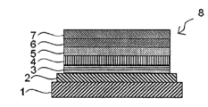
- OLEDs usually have a hole injection layer, a hole transport layer, an organic light emitting layer, an electron transport layer, etc. between an anode and a cathode, and materials suitable for each layer are being developed.
- red, green, and blue light emitting colors which are all under development.
- examples of methods for forming the organic layer of the organic electroluminescent device include vacuum evaporation method and wet film formation method (coating method).
- the vacuum evaporation method has the advantage that since it is easy to stack layers, charge injection from the anode and/or cathode can be improved and excitons can be easily confined in the light emitting layer.
- the wet film formation method does not require a vacuum process and can easily be applied to a large area.By using a coating solution that is a mixture of multiple materials with various functions, it is possible to easily create multiple materials with various functions. It has advantages such as being able to form a layer containing the following materials. Therefore, in recent years, research and development of organic electroluminescent devices using coating methods has been actively conducted.
- Patent Documents 1 to 3 disclose organic electroluminescent elements having a hole injection layer containing polystyrene sulfonic acid and a light emitting layer containing a light emitting material having a polycyclic heterocyclic compound skeleton containing boron and nitrogen. Are listed. Further, research and development is being conducted to utilize the triplet excited state, which accounts for 75% of the excitons generated in organic electroluminescent devices.
- Non-Patent Document 1 as a means to increase the luminous efficiency of an organic electroluminescent device, in addition to a luminescent material having a polycyclic heterocyclic compound skeleton, a luminescent material having a polycyclic heterocyclic compound skeleton is added to a luminescent layer formed by a vacuum evaporation method to assist luminescence. It has been reported that an organometallic compound containing iridium, which is a phosphorescent material, as a central metal is used as a material for this purpose.
- Patent Documents 1 to 3 use a hole injection layer containing strongly acidic polystyrene sulfonic acid, so that water and sulfonic acid groups taken in during formation of the hole injection layer are This is thought to be caused by a reaction with the ring heterocyclic compound during device operation. Furthermore, in the technique disclosed in Non-Patent Document 1, it is necessary to keep the deposition rate ratio of three or more materials constant when the host material is included, making it difficult to obtain stable performance.
- the present invention has been made in view of the above-mentioned conventional circumstances, and an object to be solved is to provide an organic electroluminescent element that has a low driving voltage, high luminous efficiency, and a long driving life.
- the present inventors discovered a hole injection layer containing a stable tetraarylborate ion that satisfies the octet rule and does not have an empty p orbital on boron, and a polycyclic heterocyclic ring containing boron.
- the above problem can be solved by using a light-emitting layer containing a compound and an organometallic compound having iridium as a central metal, and by satisfying a specific relationship between the triplet energy levels of the organometallic compound and the polycyclic heterocyclic compound. They discovered this and completed the present invention.
- boron and a hole injection layer containing a crosslinked product of an electron-accepting compound having a crosslinking group, particularly preferably a crosslinked product of a tetraarylborate ion having a crosslinking group By using a light-emitting layer containing a polycyclic heterocyclic compound and an organometallic compound containing iridium as a central metal, the triplet energy levels of the organometallic compound and the polycyclic heterocyclic compound satisfy a specific relationship. The inventors have discovered that the problem can be solved and have completed the present invention.
- the gist of the present invention is as follows.
- Aspect 1 of the present invention is An organic electroluminescent device having an anode, a cathode, a light emitting layer, and a hole injection layer,
- the light emitting layer is provided between the anode and the cathode
- the hole injection layer is provided between the anode and the light emitting layer
- the light emitting layer contains a polycyclic heterocyclic compound represented by the following formula (1) and an organometallic compound represented by the following formula (201), the polycyclic heterocyclic compound and the organometallic compound satisfy the following relational formula (E-1), T1A ⁇ T1B Formula (E-1) (In formula (E-1), T1A: triplet energy level (eV) of the organometallic compound T1B: triplet energy level (eV) of the polycyclic heterocyclic compound represents.
- the hole injection layer is an organic electroluminescent device containing tetraarylborate ions.
- ring Cy 1 , ring Cy 2 , ring Cy 3 and ring Cy 4 each independently represent a 5-membered or 6-membered aromatic hydrocarbon ring or aromatic heterocycle. Ring Cy 1 , Cy 2 , Cy 3 and Cy 4 may further have a fused ring.
- R represents a hydrogen atom or a substituent
- x, y, z, and w each represent the maximum number of bonds that R can bond to ring Cy 1 , ring Cy 2 , ring Cy 3 , and ring Cy 4 .
- Q 11 , Q 12 , Q 21 and Q 22 represent NR, O or S. When multiple R's exist, they may be the same or different.
- adjacent R may be combined with each other or with ring Cy 1 , ring Cy 2 , ring Cy 3 and ring Cy 4 adjacent to R to form a ring.
- Ring A201 represents an aromatic hydrocarbon ring structure which may have a substituent or an aromatic heterocyclic structure which may have a substituent.
- Ring A202 represents an aromatic heterocyclic structure which may have a substituent.
- R 201 and R 202 each independently have a structure represented by the above formula (202). When a plurality of R 201 and R 202 exist, they may be the same or different.
- Ar 201 and Ar 203 each independently represent an aromatic hydrocarbon ring structure that may have a substituent or an aromatic heterocyclic structure that may have a substituent.
- Ar 202 is an aromatic hydrocarbon ring structure that may have a substituent, an aromatic heterocyclic structure that may have a substituent, or an aliphatic hydrocarbon structure that may have a substituent. represents.
- Ar 201 , Ar 202 and Ar 203 When a plurality of Ar 201 , Ar 202 and Ar 203 exist, they may be the same or different.
- * represents bonding to ring A201 or ring A202.
- B 201 -L 200 -B 202 represents an anionic bidentate ligand.
- B 201 and B 202 each independently represent a carbon atom, an oxygen atom, or a nitrogen atom, and these atoms may be atoms constituting a ring, in which case B 201 and/or B 202 have a ring structure.
- L 200 represents a single bond or an atomic group that constitutes a bidentate ligand together with B 201 and B 202 .
- B 201 -L 200 -B 202 When a plurality of B 201 -L 200 -B 202 exist, they may be the same or different.
- i1 and i2 each independently represent an integer from 0 to 12.
- i3 is an integer of 0 or more with an upper limit of the number that can be replaced by Ar 202 .
- j is an integer of 0 or more with an upper limit of the number that can be replaced by Ar 201 .
- k1 and k2 are each independently an integer of 0 or more, with the upper limit being the number that can be substituted into ring A201 and ring A202.
- m is an integer from 1 to 3. ]
- Aspect 2 of the present invention is the organic compound according to aspect 1, wherein the hole injection layer contains the tetraarylborate ion having a crosslinking group and/or a crosslinked product of the tetraarylborate ion having a crosslinking group. It is an electroluminescent device.
- Aspect 3 of the present invention is The organic electroluminescent device according to aspect 1 or 2, wherein the polycyclic heterocyclic compound represented by formula (1) is represented by formula (2-1) or formula (2-2).
- Q 31 and Q 32 represent O or S.
- R is the same as in formula (1) above, and when a plurality of R's exist, they are independent from each other and may be the same or different. When R is a substituent, it may combine with adjacent R's to form a ring. ]
- Aspect 4 of the present invention is The organic electroluminescent device according to aspect 1 or 2, wherein the polycyclic heterocyclic compound represented by formula (1) is represented by formula (2-3).
- Q 31 and Q 32 represent O or S.
- R is the same as in formula (1) above, and when a plurality of R's exist, they are independent from each other and may be the same or different. When R is a substituent, it may combine with adjacent R's to form a ring.
- R' represents a hydrogen atom or a substituent, and when multiple R's exist, they are independent from each other and may be the same or different.
- Aspect 5 of the present invention is The organic electroluminescent device according to any one of aspects 1 to 4, wherein the light emitting layer further contains a host material.
- Aspect 6 of the present invention is The organic electroluminescent device according to any one of aspects 1 to 5, wherein the tetraarylborate ion is represented by the following formula (112).
- Ar 1 , Ar 2 , Ar 3 and Ar 4 each independently have an aromatic hydrocarbon ring group which may have a substituent and/or a crosslinking group, a substituent and/or a crosslinking group.
- an aromatic hydrocarbon ring group that may have a substituent and/or a crosslinking group; represents a monovalent group in which multiple structures selected from are connected, At least one of Ar 1 , Ar 2 , Ar 3 and Ar 4 has a fluorine atom or a fluorine-substituted alkyl group as a substituent.
- Aspect 7 of the present invention is The organic electroluminescent device according to aspect 6, wherein at least one of Ar 1 , Ar 2 , Ar 3 and Ar 4 in the formula (112) is a group represented by the following formula (113).
- R A each independently represents an aromatic hydrocarbon ring group which may have a substituent and/or a crosslinking group, an aromatic heterocyclic group which may have a substituent and/or a crosslinking group, a substituted A monovalent structure in which a plurality of structures selected from an aromatic hydrocarbon ring group which may have a group and/or a crosslinking group, and an aromatic heterocyclic group which may have a substituent and/or a crosslinking group are connected.
- F 4 represents substitution of 4 fluorine atoms
- F (5-m) represents that 5-m fluorine atoms are independently substituted
- k each independently represents an integer from 0 to 5
- Each m independently represents an integer of 0 to 5. * represents the bonding position.
- Aspect 8 of the present invention is The organic electroluminescent device according to any one of Aspects 2 to 7, wherein the crosslinking group is represented by any of the following formulas (X1) to (X18).
- the benzene ring and the naphthalene ring may have a substituent. Furthermore, the substituents may be bonded to each other to form a ring.
- R X in formula (X4), formula (X5), formula (X6) and formula (X10) each independently represents an alkyl group which may have a substituent. * in formulas (X1) to (X18) represents a bonding position. )
- Aspect 9 of the present invention is The organic electroluminescent device according to aspect 8, wherein the crosslinking group is represented by any one of the formulas (X1) to (X4).
- Aspect 10 of the present invention is An organic EL display device or organic EL lighting comprising the organic electroluminescent element according to any one of aspects 1 to 9.
- a method for manufacturing an organic electroluminescent device having an anode, a hole injection layer, a light emitting layer, and a cathode in this order on a substrate comprising:
- the method for manufacturing the organic electroluminescent device includes a step of forming the hole injection layer by a wet film formation method using a composition for forming a hole injection layer, and a step of forming the hole injection layer by a wet film formation method using a composition for forming a light emitting layer.
- the composition for forming a hole injection layer contains a tetraarylborate ion and an organic solvent
- the composition for forming a light emitting layer includes a polycyclic heterocyclic compound represented by the following formula (1), an organometallic compound represented by the following formula (201), and an organic solvent,
- the polycyclic heterocyclic compound and the organometallic compound satisfy the following relational formula (E-1), T1A ⁇ T1B Formula (E-1) (In formula (E-1), T1A: Triplet energy level (eV) of the organometallic compound T1B: Triplet energy level (eV) of the polycyclic heterocyclic compound represents. )
- ring Cy 1 , ring Cy 2 , ring Cy 3 and ring Cy 4 each independently represent a 5-membered or 6-membered aromatic hydrocarbon ring or aromatic heterocycle. Ring Cy 1 , Cy 2 , Cy 3 and Cy 4 may further have a fused ring.
- R represents a hydrogen atom or a substituent
- x, y, z, and w each represent the maximum number of bonds that R can bond to ring Cy 1 , ring Cy 2 , ring Cy 3 , and ring Cy 4 .
- Q 11 , Q 12 , Q 21 and Q 22 represent NR, O or S. When multiple R's exist, they may be the same or different.
- adjacent R may be combined with each other or with ring Cy 1 , ring Cy 2 , ring Cy 3 and ring Cy 4 adjacent to R to form a ring.
- Ring A201 represents an aromatic hydrocarbon ring structure which may have a substituent or an aromatic heterocyclic structure which may have a substituent.
- Ring A202 represents an aromatic heterocyclic structure which may have a substituent.
- R 201 and R 202 each independently have a structure represented by the above formula (202). When a plurality of R 201 and R 202 exist, they may be the same or different.
- Ar 201 and Ar 203 each independently represent an aromatic hydrocarbon ring structure that may have a substituent or an aromatic heterocyclic structure that may have a substituent.
- Ar 202 is an aromatic hydrocarbon ring structure that may have a substituent, an aromatic heterocyclic structure that may have a substituent, or an aliphatic hydrocarbon structure that may have a substituent. represents.
- Ar 201 , Ar 202 and Ar 203 When a plurality of Ar 201 , Ar 202 and Ar 203 exist, they may be the same or different.
- * represents bonding to ring A201 or ring A202.
- B 201 -L 200 -B 202 represents an anionic bidentate ligand.
- B 201 and B 202 each independently represent a carbon atom, an oxygen atom, or a nitrogen atom, and these atoms may be atoms constituting a ring, in which case B 201 and/or B 202 have a ring structure.
- L 200 represents a single bond or an atomic group that constitutes a bidentate ligand together with B 201 and B 202 .
- B 201 -L 200 -B 202 When a plurality of B 201 -L 200 -B 202 exist, they may be the same or different.
- i1 and i2 each independently represent an integer from 0 to 12.
- i3 is an integer of 0 or more with an upper limit of the number that can be replaced by Ar 202 .
- j is an integer of 0 or more with an upper limit of the number that can be replaced by Ar 201 .
- k1 and k2 are each independently an integer of 0 or more, with the upper limit being the number that can be substituted into ring A201 and ring A202.
- m is an integer from 1 to 3. ]
- Aspect 12 of the present invention is The method for producing an organic electroluminescent device according to aspect 11, wherein the polycyclic heterocyclic compound represented by formula (1) is represented by formula (2-1) or formula (2-2).
- Q 31 and Q 32 represent O or S.
- R is the same as in formula (1) above, and when a plurality of R's exist, they are independent from each other and may be the same or different. When R is a substituent, it may combine with adjacent R's to form a ring. ]
- Aspect 13 of the present invention is The method for producing an organic electroluminescent device according to aspect 11, wherein the polycyclic heterocyclic compound represented by formula (1) is represented by formula (2-3).
- Q 31 and Q 32 represent O or S.
- R is the same as in formula (1) above, and when a plurality of R's exist, they are independent from each other and may be the same or different. When R is a substituent, it may combine with adjacent R's to form a ring.
- R' represents a hydrogen atom or a substituent, and when multiple R's exist, they are independent from each other and may be the same or different.
- Aspect 14 of the present invention is a method for producing an organic electroluminescent device according to any one of Aspects 11 to 13, wherein the tetraarylborate ion has a crosslinking group.
- Aspect 15 of the present invention is The method for producing an organic electroluminescent device according to any one of aspects 11 to 14, wherein the tetraarylborate ion is represented by the following formula (112).
- Ar 1 , Ar 2 , Ar 3 and Ar 4 each independently have an aromatic hydrocarbon ring group which may have a substituent and/or a crosslinking group, a substituent and/or a crosslinking group.
- an aromatic hydrocarbon ring group that may have a substituent and/or a crosslinking group; represents a monovalent group in which multiple structures selected from are connected, At least one of Ar 1 , Ar 2 , Ar 3 and Ar 4 has a fluorine atom or a fluorine-substituted alkyl group as a substituent.
- Aspect 16 of the present invention is Aspect 14, wherein the composition for forming a hole injection layer is a composition obtained through a step of dissolving or dispersing an electron-accepting ion compound having a tetraarylborate ion structure and a hole-transporting material in an organic solvent. 18.
- Aspect 17 of the present invention is Any one of aspects 14 to 16, wherein in the step of forming the hole injection layer, a crosslinked product of the tetraarylborate ion is formed by applying and drying the hole injection layer forming composition and then heating it. 1.
- the organic electroluminescent device of the present invention exhibits excellent device characteristics, particularly low driving voltage, high luminous efficiency, and long driving life.
- FIG. 1 is a schematic cross-sectional view showing a structural example of an organic electroluminescent device of the present invention.
- an organic electroluminescent device an organic EL display device including the organic electroluminescent device, and an organic EL lighting device including the organic electroluminescent device, which are one embodiment of the present invention, will be described in detail.
- the following description is an example (representative example) of the embodiment of the present invention, but the present invention is not limited to these contents unless the gist thereof is exceeded.
- the organic electroluminescent device is an organic electroluminescent device having an anode, a cathode, a light emitting layer, and a hole injection layer,
- the light emitting layer is provided between the anode and the cathode
- the hole injection layer is provided between the anode and the light emitting layer
- the light emitting layer contains a polycyclic heterocyclic compound represented by the following formula (1) and an organometallic compound represented by the following formula (201), the polycyclic heterocyclic compound and the organometallic compound satisfy the following relational formula (E-1),
- the hole injection layer contains tetraarylborate ions.
- T1A ⁇ T1B Formula (E-1) In formula (E-1), T1A: Triplet energy level (eV) of the organometallic compound T1B: Triplet energy level (eV) of the polycyclic heterocyclic compound represents. )
- ring Cy 1 , ring Cy 2 , ring Cy 3 and ring Cy 4 each independently represent a 5-membered or 6-membered aromatic hydrocarbon ring or aromatic heterocycle. Ring Cy 1 , Cy 2 , Cy 3 and Cy 4 may further have a fused ring.
- R represents a hydrogen atom or a substituent
- x, y, z, and w each represent the maximum number of bonds that R can bond to ring Cy 1 , ring Cy 2 , ring Cy 3 , and ring Cy 4 .
- Q 11 , Q 12 , Q 21 and Q 22 represent NR, O or S. When multiple R's exist, they may be the same or different.
- adjacent R may be combined with each other or with ring Cy 1 , ring Cy 2 , ring Cy 3 and ring Cy 4 adjacent to R to form a ring.
- Ring A201 represents an aromatic hydrocarbon ring structure which may have a substituent or an aromatic heterocyclic structure which may have a substituent.
- Ring A202 represents an aromatic heterocyclic structure which may have a substituent.
- R 201 and R 202 each independently have a structure represented by the above formula (202). When a plurality of R 201 and R 202 exist, they may be the same or different.
- Ar 201 and Ar 203 each independently represent an aromatic hydrocarbon ring structure that may have a substituent or an aromatic heterocyclic structure that may have a substituent.
- Ar 202 is an aromatic hydrocarbon ring structure that may have a substituent, an aromatic heterocyclic structure that may have a substituent, or an aliphatic hydrocarbon structure that may have a substituent. represents. When a plurality of Ar 201 , Ar 202 and Ar 203 exist, they may be the same or different. "*" represents bonding to ring A201 or ring A202.
- B 201 -L 200 -B 202 represents an anionic bidentate ligand.
- B 201 and B 202 each independently represent a carbon atom, an oxygen atom, or a nitrogen atom, and these atoms may be atoms constituting a ring, in which case B 201 and/or B 202 have a ring structure.
- L 200 represents a single bond or an atomic group that constitutes a bidentate ligand together with B 201 and B 202 .
- B 201 -L 200 -B 202 When a plurality of B 201 -L 200 -B 202 exist, they may be the same or different.
- i1 and i2 each independently represent an integer from 0 to 12.
- i3 is an integer of 0 or more with an upper limit of the number that can be replaced by Ar 202 .
- j is an integer of 0 or more with an upper limit of the number that can be replaced by Ar 201 .
- k1 and k2 are each independently an integer of 0 or more, with the upper limit being the number that can be substituted into ring A201 and ring A202.
- m is an integer from 1 to 3. ]
- a polycyclic heterocyclic compound containing boron has an empty p-orbital on boron, and is particularly likely to react with electron-donating substances. As a result of the reaction, an oxide of the electron-donating substance is generated, and this oxide may cause further deterioration reactions during operation.
- the tetraarylborate ion which has a stable structure that satisfies the octet rule and does not have an empty p orbital on boron, has the effect of stabilizing a cation obtained by oxidizing an electron-donating substance. Therefore, it is estimated that by using tetraarylborate ions, it is possible to suppress the deterioration reaction during driving.
- an electron-accepting compound is used in the hole injection layer to promote hole injection from the metal anode and reduce the driving voltage.
- the electron accepting compound in the hole injection layer diffuses and reaches the light emitting layer. It is thought that this reacted with polycyclic heterocyclic compounds containing boron during device operation, leading to an increase in drive voltage and a reduction in drive life.
- the electron-accepting compound is immobilized in the hole-injection layer by allowing the cross-linking reaction to proceed when forming the hole-injection layer by containing a cross-linking group in the electron-accepting compound, It is considered that the electron-accepting compound does not diffuse when forming the layer above the hole injection layer by a wet film formation method. Therefore, it is presumed that by using an electron-accepting compound having a crosslinking group, it is possible to suppress the deterioration reaction during driving.
- the organometallic compound contains a heavy atom such as iridium
- the heavy atom effect promotes intersystem crossing between excited triplet and excited singlet. Since intersystem crossing is promoted, the energy of the excited triplet, which accounts for 75% of the excitons generated by applying voltage to the organic electroluminescent device, is used to emit light from the polycyclic heterocyclic compound containing boron, which is a fluorescent material. It is estimated that it can be used effectively.
- a polycyclic heterocyclic compound containing boron represented by formula (1) and an organometallic compound represented by formula (201) are used in the light emitting layer, and there is no empty p orbital on boron.
- the above problem is solved by using a hole injection layer containing a stable tetraarylborate ion that satisfies the octet rule, and by satisfying a specific relationship between the triplet energy levels of the organometallic compound and the polycyclic heterocyclic compound. They have discovered that it is possible to do so, and have completed the present invention.
- the light-emitting layer of the present invention contains a polycyclic heterocyclic compound represented by formula (1) and an organometallic compound represented by formula (201), and satisfies the following relational formula (E-1).
- T1A ⁇ T1B Formula (E-1) T1A: triplet energy level (eV) of the organometallic compound
- T1B Triplet energy level (eV) of the polycyclic heterocyclic compound represents.
- the organometallic compound efficiently transfers the energy of the excited triplet generated in the light emitting layer to the polycyclic heterocyclic compound, and the polycyclic heterocyclic compound Emits light. That is, in the present invention, the polycyclic heterocyclic compound is a luminescent material.
- the polycyclic heterocyclic compound in the present invention preferably satisfies the following relational formula (E-2).
- ⁇ EST S1B-T1B ⁇ 0.30eV Formula (E-2) (S1B: Singlet energy level (eV) of the polycyclic heterocyclic compound)
- S1B Singlet energy level (eV) of the polycyclic heterocyclic compound
- ⁇ EST in formula (E-2) is 0.30 eV or less, preferably 0.25 eV or less, and more preferably 0.20 eV or less.
- T1A is preferably 1.90 eV or more, more preferably 2.00 eV or more, even more preferably 2.10 eV or more, and preferably 3.00 eV or less, more preferably 2.80 eV or less, even more preferably 2.70 eV or less. It is.
- T1A can be 2.10 eV or more and 2.80 eV or less as a preferred embodiment.
- T1A, T1B, and S1B can be determined by the following method.
- S1B, T1A and T1B can be determined from the peak wavelengths of the fluorescence spectrum and phosphorescence spectrum, respectively.
- the fluorescence spectrum and phosphorescence spectrum can be measured using a spectrophotometer, for example, using a spectrofluorometer F-7000 manufactured by Hitachi High-Tech Science.
- a solution prepared by dissolving a compound in an appropriate organic solvent at a concentration of about 10 -6 to 10 -5 M is used as a sample. Fluorescence spectra are measured at room temperature. Phosphorescence is measured by cooling to 77K with liquid nitrogen.
- the polycyclic heterocyclic compound in the present invention satisfies the following relational formula (E-3).
- PkA ⁇ PkB Formula (E-3) In formula (E-3), PkA: Maximum emission wavelength (nm) of the organometallic compound PkB: Maximum emission wavelength (nm) of the polycyclic heterocyclic compound represents. )
- the organometallic compound efficiently transfers the excitation energy generated in the light emitting layer to the polycyclic heterocyclic compound, and the polycyclic heterocyclic compound It emits light.
- PkA is preferably 550 nm or more and 650 nm or less, the lower limit is more preferably 560 nm or more, more preferably 570 nm or more, and the upper limit is still more preferably 630 nm or less, more preferably 610 nm or less.
- PkB may satisfy the above formula (E-3), but preferably the difference between PkB and PkA is usually 80 nm or less, preferably 50 nm or less, more preferably 40 nm or less, more preferably 30 nm or less, particularly preferably 25 nm. It is as follows.
- the excitation energy of the organometallic compound is efficiently transferred to the polycyclic heterocyclic compound, resulting in a higher performance element.
- the polycyclic heterocyclic compound of the present invention having the relationship of formula (E-3) efficiently emits light at long wavelengths, particularly in the red light emitting region, and It is thought that a high-performance element can be obtained.
- PkA and PkB are measured by the following method.
- a solution of the organometallic compound or polycyclic heterocyclic compound of the present invention dissolved in an organic solvent at a concentration of 1 ⁇ 10 ⁇ 4 mol/L or less was prepared, and a solution was prepared using a spectrophotometer (organic EL quantum manufactured by Hamamatsu Photonics Co., Ltd.).
- the emission spectrum of the solution is measured using a yield measuring device C9920-02).
- the wavelength showing the maximum value of the obtained emission spectrum intensity is defined as the maximum emission wavelength in the present invention.
- the organic solvent for dissolving the organometallic compound and polycyclic heterocyclic compound toluene, 2-methyltetrahydrofuran, etc. are preferably used, and toluene is usually preferred.
- the light-emitting layer contains a polycyclic heterocyclic compound represented by formula (1) as a light-emitting compound.
- ring Cy 1 , ring Cy 2 , ring Cy 3 and ring Cy 4 each independently represent a 5-membered or 6-membered aromatic hydrocarbon ring or aromatic heterocycle. Ring Cy 1 , Cy 2 , Cy 3 and Cy 4 may further have a fused ring.
- R represents a hydrogen atom or a substituent
- x, y, z, and w each represent the maximum number of bonds that R can bond to ring Cy 1 , ring Cy 2 , ring Cy 3 , and ring Cy 4 .
- Q 11 , Q 12 , Q 21 and Q 22 represent NR, O or S. When multiple R's exist, they may be the same or different.
- adjacent R may be combined with each other or with ring Cy 1 , ring Cy 2 , ring Cy 3 and ring Cy 4 adjacent to R to form a ring.
- the polycyclic heterocyclic compound represented by formula (1) is preferably a compound represented by formula (2-1) or formula (2-2).
- Q 31 and Q 32 represent O or S.
- R is the same as in formula (1) above, and when a plurality of R's exist, they are independent from each other and may be the same or different. When R is a substituent, it may combine with adjacent R's to form a ring. ]
- the polycyclic heterocyclic compound represented by formula (1) is more preferably a compound represented by formula (2-3).
- Q 31 and Q 32 represent O or S.
- R is the same as in formula (1) above, and when a plurality of R's exist, they are independent from each other and may be the same or different. When R is a substituent, it may combine with adjacent R's to form a ring.
- R' represents a hydrogen atom or a substituent, and when multiple R's exist, they are independent from each other and may be the same or different.
- the above R is a hydrogen atom or the following [substituted It is more preferable that the substituent is a substituent selected from group W1]. In the polycyclic heterocyclic compound represented by the formula (2-3), it is more preferable that the R' is selected from the following [R'].
- R is a hydrogen atom or a substituent, and when R is a substituent, it is an arbitrary substituent, but preferably a substituent selected from the following [substituent group W1].
- Two or more adjacent R's may be bonded to each other to form an aliphatic or aromatic hydrocarbon or heteroaromatic monocyclic or fused ring.
- the alkyl group, the alkoxy group, the alkylthio group, the alkenyl group, and the alkynyl group may be further substituted with one or more R', and one -CH 2 - group or two or more of these groups
- one or more hydrogen atoms in these groups may be substituted with D, F, Cl, Br, I or -CN.
- the aromatic hydrocarbon group, the heteroaromatic group, the aryloxy group, the arylthio group, the aralkyl group, the heteroaralkyl group, the diarylamino group, the arylheteroarylamino group, and the diheteroarylamino group each independently may be further substituted with one or more R'.
- Two or more adjacent R's may be bonded to each other to form an aliphatic or aromatic hydrocarbon or heteroaromatic monocyclic or fused ring.
- the alkyl group, the alkoxy group, the alkylthio group, the alkenyl group, and the alkynyl group may be further substituted with one or more R'', and one -CH2- group or two or more of these groups.
- one or more hydrogen atoms in these groups may be substituted with D, F, Cl, Br, I or -CN.
- the aromatic hydrocarbon group, the heteroaromatic group, the aryloxy group, the arylthio group, the aralkyl group, the heteroaralkyl group, the diarylamino group, the arylheteroarylamino group, and the diheteroarylamino group may be further substituted with one or more R''.
- R'' is each independently a hydrogen atom, D, F, -CN, an aliphatic hydrocarbon group having 1 to 20 carbon atoms, an aromatic hydrocarbon group having 1 to 20 carbon atoms, or an aromatic hydrocarbon group having 1 to 20 carbon atoms. selected from heteroaromatic groups. Two or more adjacent R'' may be bonded to each other to form an aliphatic or aromatic hydrocarbon or heteroaromatic monocyclic or fused ring.
- the polycyclic heterocyclic compound represented by formula (1) is not particularly limited, but specifically includes the following structures.
- organometallic compounds are Groups 7 to 11 of the long-period periodic table (hereinafter, unless otherwise specified, "periodic table” refers to the long-period table).
- Preferred metals selected from Groups 7 to 11 of the periodic table include ruthenium, rhodium, palladium, silver, rhenium, osmium, iridium, platinum, gold, and the like, with iridium or platinum being more preferred.
- the organometallic compound is a Werner type complex or an organometallic complex.
- Preferred ligands for the complex include ligands in which a (hetero)aryl group is linked to pyridine, pyrazole, phenanthroline, etc., such as (hetero)arylpyridine ligands and (hetero)arylpyrazole ligands. Pyridine ligands and phenylpyrazole ligands are preferred.
- (hetero)aryl represents an aryl group or a heteroaryl group. Due to the heavy atom effect of the metal, intersystem crossing from an excited singlet to an excited triplet occurs in an organometallic compound containing the metal, and the relaxation time from an excited triplet to a ground state is shortened to a certain extent.
- the excited state generated by voltage application to the organic electroluminescent element can be transferred to the polycyclic heterocyclic ring by electron exchange interaction or dipole-dipole interaction. It is presumed that it can be delivered to compounds and that polycyclic heterocyclic compounds can be efficiently illuminated.
- organometallic complexes containing iridium a metal compound represented by formula (201) is preferable.
- the light emitting layer contains an organometallic compound represented by formula (201).
- Ring A201 represents an aromatic hydrocarbon ring structure which may have a substituent or an aromatic heterocyclic structure which may have a substituent.
- Ring A202 represents an aromatic heterocyclic structure which may have a substituent.
- R 201 and R 202 each independently have a structure represented by the above formula (202). When a plurality of R 201 and R 202 exist, they may be the same or different.
- Ar 201 and Ar 203 each independently represent an aromatic hydrocarbon ring structure that may have a substituent or an aromatic heterocyclic structure that may have a substituent.
- Ar 202 is an aromatic hydrocarbon ring structure that may have a substituent, an aromatic heterocyclic structure that may have a substituent, or an aliphatic hydrocarbon structure that may have a substituent. represents.
- Ar 201 , Ar 202 and Ar 203 When a plurality of Ar 201 , Ar 202 and Ar 203 exist, they may be the same or different.
- * represents bonding to ring A201 or ring A202.
- B 201 -L 200 -B 202 represents an anionic bidentate ligand.
- B 201 and B 202 each independently represent a carbon atom, an oxygen atom, or a nitrogen atom, and these atoms may be atoms constituting a ring, in which case B 201 and/or B 202 have a ring structure.
- L 200 represents a single bond or an atomic group that constitutes a bidentate ligand together with B 201 and B 202 .
- B 201 -L 200 -B 202 When a plurality of B 201 -L 200 -B 202 exist, they may be the same or different.
- i1 and i2 each independently represent an integer from 0 to 12.
- i3 is an integer of 0 or more with an upper limit of the number that can be replaced by Ar 202 .
- j is an integer of 0 or more with an upper limit of the number that can be replaced by Ar 201 .
- k1 and k2 are each independently an integer of 0 or more, with the upper limit being the number that can be substituted into ring A201 and ring A202.
- m is an integer from 1 to 3. ]
- the aromatic hydrocarbon ring in ring A201 is preferably an aromatic hydrocarbon ring having 6 to 30 carbon atoms, and specifically, a benzene ring, a naphthalene ring, an anthracene ring, a triphenyl ring, an acenaphthene ring, a fluoranthene ring, A fluorene ring is preferred.
- the aromatic heterocycle in ring A201 is preferably an aromatic heterocycle having 3 to 30 carbon atoms and containing a nitrogen atom, an oxygen atom, or a sulfur atom as a hetero atom, and more preferably a furan ring or a benzofuran ring. , a thiophene ring, and a benzothiophene ring.
- the ring A201 is more preferably a benzene ring, a naphthalene ring, or a fluorene ring, particularly preferably a benzene ring or a fluorene ring, and most preferably a benzene ring.
- the aromatic heterocycle in ring A202 is preferably an aromatic heterocycle having 3 to 30 carbon atoms and containing a nitrogen atom, an oxygen atom, or a sulfur atom as a heteroatom, and specifically, a pyridine ring. , pyrazine ring, pyrimidine ring, imidazole ring, oxazole ring, and thiazole ring, most preferably a pyridine ring.
- the plurality of rings A201 and the plurality of rings A202 may be the same or different.
- Preferred combinations of ring A201 and ring A202 when expressed as (ring A201-ring A202), are (benzene ring-pyridine ring), (benzene ring-quinoline ring), (benzene ring-quinoxaline ring), (benzene ring- (quinazoline ring), (benzene ring-imidazole ring), (benzene ring-benzothiazole ring), and most preferably (benzene ring-pyridine ring).
- substituents that ring A201 and ring A202 may have can be arbitrarily selected, but are preferably one or more substituents selected from substituent group S described below.
- the substituents bonded to ring A201, the substituents bonded to ring A202, or the substituents bonded to ring A201 and the substituents bonded to ring A202 may bond to each other to form a ring.
- R 201 and R 202 are each independently a structure represented by the above formula (202), and “*” represents bonding to ring A201 or ring A202.
- R 201 and R 202 may be the same or different. When a plurality of R 201 and R 202 exist, they may be the same or different. That is, when multiple R 201s exist, they may be the same or different; when multiple R 202s exist, they may be the same or different.
- Ar 201 and Ar 203 each independently represent an aromatic hydrocarbon ring structure that may have a substituent or an aromatic heterocyclic structure that may have a substituent.
- Ar 202 is an aromatic hydrocarbon ring structure that may have a substituent, an aromatic heterocyclic structure that may have a substituent, or an aliphatic hydrocarbon structure that may have a substituent. represents.
- Ar 201 , Ar 202 and Ar 203 may be the same or different.
- Ar 201s when there are multiple Ar 201s , they may be the same or different; when there are multiple Ar 202s , they may be the same or different; and when there are multiple Ar 203s , they may be the same or different. If so, they may be the same or different.
- Ar 201 , Ar 202 , and Ar 203 is an aromatic hydrocarbon ring structure which may have a substituent, the aromatic hydrocarbon ring structure is preferably an aromatic hydrocarbon ring structure having 6 to 30 carbon atoms.
- a hydrocarbon ring and specifically, a benzene ring, a naphthalene ring, an anthracene ring, a triphenyl ring, an acenaphthene ring, a fluoranthene ring, and a fluorene ring are preferable, and a benzene ring, a naphthalene ring, and a fluorene ring are more preferable, and the most preferable are a benzene ring, a naphthalene ring, and a fluorene ring.
- it is a benzene ring.
- any of Ar 201 , Ar 202 , and Ar 203 is a fluorene ring that may have a substituent
- the 9- and 9'-positions of the fluorene ring have a substituent or are bonded to adjacent structures. It is preferable that
- Ar 201 , Ar 202 , and Ar 203 is a benzene ring which may have a substituent
- Ar 201 , Ar 202 , and Ar 203 is an aromatic heterocyclic structure which may have a substituent
- the aromatic heterocyclic structure preferably contains a nitrogen atom, an oxygen atom, or An aromatic heterocycle having 3 to 30 carbon atoms and containing any sulfur atom, specifically a pyridine ring, pyrimidine ring, pyrazine ring, triazine ring, imidazole ring, oxazole ring, thiazole ring, benzothiazole ring , a benzoxazole ring, a benzimidazole ring, a quinoline ring, an isoquinoline ring, a quinoxaline ring, a quinazoline ring, a naphthyridine ring, a phenanthridine ring, a carbazole ring, a dibenzofuran ring, and a dibenzothiophene ring, and more preferably a pyridine ring and
- Ar 201 , Ar 202 , and Ar 203 is a carbazole ring which may have a substituent
- the N-position of the carbazole ring may have a substituent or be bonded to an adjacent structure. preferable.
- the aliphatic hydrocarbon structure is an aliphatic hydrocarbon structure having a linear, branched, or cyclic structure, preferably a carbon It is an aliphatic hydrocarbon having a carbon number of 1 or more and 24 or less, more preferably an aliphatic hydrocarbon having a carbon number of 1 or more and 12 or less, and even more preferably an aliphatic hydrocarbon having a carbon number of 1 or more and 8 or less.
- i1 and i2 are each independently preferably an integer of 1 to 12, more preferably an integer of 1 to 8, and even more preferably an integer of 1 to 6. Within this range, it is expected that solubility and charge transport properties will be improved.
- i3 preferably represents an integer of 0 to 5, more preferably an integer of 0 to 2, and more preferably 0 or 1.
- j preferably represents an integer of 0 to 2, more preferably 0 or 1.
- k1 and k2 preferably represent an integer of 0 to 3, more preferably an integer of 1 to 3, more preferably 1 or 2, particularly preferably 1.
- the substituents that Ar 201 , Ar 202 , and Ar 203 may have can be arbitrarily selected, but are preferably one or more substituents selected from the substituent group S described below, and more preferably hydrogen An atom, an alkyl group, or an aryl group, particularly preferably a hydrogen atom or an alkyl group, and most preferably an unsubstituted (hydrogen atom).
- the substituent is preferably a group selected from the following substituent group S.
- (Substituent group S) ⁇ Alkyl group, preferably an alkyl group having 1 to 20 carbon atoms, more preferably an alkyl group having 1 to 12 carbon atoms, still more preferably an alkyl group having 1 to 8 carbon atoms, particularly preferably an alkyl group having 1 to 6 carbon atoms .
- Alkyl groups may be straight chain or branched.
- -Alkoxy group preferably an alkoxy group having 1 to 20 carbon atoms, more preferably an alkoxy group having 1 to 12 carbon atoms, still more preferably an alkoxy group having 1 to 6 carbon atoms.
- -Aryloxy group preferably an aryloxy group having 6 to 20 carbon atoms, more preferably an aryloxy group having 6 to 14 carbon atoms, even more preferably an aryloxy group having 6 to 12 carbon atoms, particularly preferably an aryloxy group having 6 to 12 carbon atoms Aryloxy group.
- - Heteroaryloxy group preferably a heteroaryloxy group having 3 to 20 carbon atoms, more preferably a heteroaryloxy group having 3 to 12 carbon atoms.
- An alkylamino group preferably an alkylamino group having 1 to 20 carbon atoms, more preferably an alkylamino group having 1 to 12 carbon atoms.
- arylamino group preferably an arylamino group having 6 to 36 carbon atoms, more preferably an arylamino group having 6 to 24 carbon atoms.
- -Aralkyl group preferably an aralkyl group having 7 to 40 carbon atoms, more preferably an aralkyl group having 7 to 18 carbon atoms, even more preferably an aralkyl group having 7 to 12 carbon atoms.
- - Heteroaralkyl group preferably a heteroaralkyl group having 7 to 40 carbon atoms, more preferably a heteroaralkyl group having 7 to 18 carbon atoms.
- Alkenyl group preferably an alkenyl group having 2 to 20 carbon atoms, more preferably an alkenyl group having 2 to 12 carbon atoms, still more preferably an alkenyl group having 2 to 8 carbon atoms, particularly preferably an alkenyl group having 2 to 6 carbon atoms .
- An alkynyl group preferably an alkynyl group having 2 to 20 carbon atoms, more preferably an alkynyl group having 2 to 12 carbon atoms.
- -Aryl group preferably an aryl group having 6 to 30 carbon atoms, more preferably an aryl group having 6 to 24 carbon atoms, still more preferably an aryl group having 6 to 18 carbon atoms, particularly preferably an aryl group having 6 to 14 carbon atoms .
- ⁇ Heteroaryl group preferably a heteroaryl group having 3 to 30 carbon atoms, more preferably a heteroaryl group having 3 to 24 carbon atoms, still more preferably a heteroaryl group having 3 to 18 carbon atoms, particularly preferably a heteroaryl group having 3 to 30 carbon atoms 14 heteroaryl groups.
- alkylsilyl group preferably an alkylsilyl group in which the alkyl group has 1 to 20 carbon atoms, more preferably an alkylsilyl group in which the alkyl group has 1 to 12 carbon atoms.
- An arylsilyl group preferably an arylsilyl group in which the aryl group has 6 to 20 carbon atoms, more preferably an arylsilyl group in which the aryl group has 6 to 14 carbon atoms.
- An alkylcarbonyl group preferably an alkylcarbonyl group having 2 to 20 carbon atoms.
- -Arylcarbonyl group preferably an arylcarbonyl group having 7 to 20 carbon atoms.
- one or more hydrogen atoms may be replaced with a fluorine atom, or one or more hydrogen atoms may be replaced with a deuterium atom.
- aryl is an aromatic hydrocarbon and heteroaryl is an aromatic heterocycle.
- substituent group S Preferred group in substituent group S
- substituent groups S preferred are alkyl groups, alkoxy groups, aryloxy groups, arylamino groups, aralkyl groups, alkenyl groups, aryl groups, heteroaryl groups, alkylsilyl groups, arylsilyl groups, and A group in which one or more hydrogen atoms are replaced with a fluorine atom, a fluorine atom, a cyano group, or -SF5 , more preferably an alkyl group, an arylamino group, an aralkyl group, an alkenyl group, an aryl group, or a hetero group.
- Aryl group a group in which one or more hydrogen atoms of these groups is replaced with a fluorine atom, a fluorine atom, a cyano group, or -SF5 , more preferably an alkyl group, an alkoxy group, an aryloxy group , an arylamino group, an aralkyl group, an alkenyl group, an aryl group, a heteroaryl group, an alkylsilyl group, an arylsilyl group, Particularly preferred are alkyl groups, arylamino groups, aralkyl groups, alkenyl groups, aryl groups, and heteroaryl groups, and most preferred are alkyl groups, arylamino groups, aralkyl groups, aryl groups, and heteroaryl groups.
- substituent groups S may further have a substituent selected from the substituent group S as a substituent.
- substituent groups S Preferable groups, more preferable groups, still more preferable groups, particularly preferable groups, and most preferable groups of the substituents that may be included are the same as the preferable groups in substituent group S, etc.
- Ar 201 is a benzene ring structure, i1 is 1 to 6, and at least one benzene ring is bonded to an adjacent structure at an ortho position or a meta position. .
- This structure is expected to improve solubility and charge transport properties.
- Ar 201 is an aromatic hydrocarbon structure or an aromatic heterocyclic structure, i1 is 1 to 6, Ar 202 is an aliphatic hydrocarbon structure, and i2 is 1 to 12, preferably 3 to 8; , Ar 203 is a benzene ring structure, and i3 is 0 or 1.
- Ar 201 is preferably the aromatic hydrocarbon structure described above, more preferably a structure in which 1 to 5 benzene rings are connected, and more preferably one benzene ring. This structure is expected to improve solubility and charge transport properties.
- Ar 201 and Ar 202 are benzene ring structures
- Ar 203 is a biphenyl or terphenyl structure
- i1 and i2 are 1 to 6
- i3 is 2, and j is 2. This structure is expected to improve solubility and charge transport properties.
- B 201 -L 200 -B 202 Structure represented by B 201 -L 200 -B 202
- B 201 -L 200 -B 202 When a plurality of B 201 -L 200 -B 202 exist, they may be the same or different.
- the structure represented by B 201 -L 200 -B 202 is preferably a structure represented by the following formula (203) or (204).
- R 211 , R 212 and R 213 represent a substituent.
- the substituent is not particularly limited, it is preferably a group selected from the above-mentioned substituent group S.
- Ring B3 represents a nitrogen atom-containing aromatic heterocyclic structure which may have a substituent.
- Ring B3 is preferably a pyridine ring.
- the substituent that ring B3 may have is not particularly limited, it is preferably a group selected from the above-mentioned substituent group S.
- the molecular weight of the organometallic compound is not particularly limited, but is preferably 10,000 or less, more preferably 5,000 or less, more preferably 4,000 or less, particularly preferably 3,000 or less. Further, the molecular weight of the organometallic compound is 1200 or more, preferably 1300 or more, and more preferably 1700 or more. It is believed that by having a molecular weight in this range, the organometallic compound does not aggregate and is uniformly mixed with the aromatic compound and/or other charge transport material of the present invention, thereby making it possible to obtain a light-emitting layer with high luminous efficiency.
- the molecular weight of the organometallic compound is high in Tg, melting point, decomposition temperature, etc., the organometallic compound and the formed light emitting layer have excellent heat resistance, and the film quality due to gas generation, recrystallization, molecular migration, etc. A larger value is preferable in that it is less likely to cause a decrease in the concentration of impurities or an increase in impurity concentration due to thermal decomposition of the material.
- the molecular weight of the organometallic compound is preferably small in terms of ease of purification of the organic compound.
- MwA/MwB is preferably 1.0 or more, more preferably 1.5 or more, and even more preferably 2. It is 0 or more. It is considered that by setting MwA/MwB within this range, energy is appropriately transferred from the organometallic compound to the polycyclic heterocyclic compound, and a light emitting layer with high luminous efficiency can be obtained.
- organometallic compound represented by formula (201) is not particularly limited, but specifically includes the following structures.
- Me means a methyl group
- Ph means a phenyl group.
- the light-emitting layer further contains a host material.
- the host material is preferably a charge transport material, and those conventionally used as materials for organic electroluminescent devices can be used.
- the charge transport material used as the host material of the light emitting layer is a material having a skeleton with excellent charge transport properties, and is selected from electron transport materials, hole transport materials, and bipolar materials capable of transporting both electrons and holes. It is preferable.
- the charge transporting material includes a material that adjusts charge transportability.
- skeletons with excellent charge transport properties include pyridine, pyrimidine, triazine, carbazole, naphthalene, perylene, pyrene, anthracene, chrysene, naphthacene, phenanthrene, coronene, fluoranthene, benzophenanthrene, fluorene, and acetonaphthofluorane.
- One type of these may be used alone, or two or more types may be used in any combination and ratio.
- pyridine preferred are pyridine, pyrimidine, triazine, carbazole, naphthalene, perylene, pyrene, anthracene, chrysene, naphthacene, phenanthrene, coronene, fluoranthene, benzophenanthrene, fluorene, acetonaphthofluoranthene and derivatives thereof, More preferred are anthracene derivatives.
- skeletons with excellent charge transport properties include aromatic structures, aromatic amine structures, triarylamine structures, dibenzofuran structures, naphthalene structures, phenanthrene structures, phthalocyanine structures, porphyrin structures, thiophene structures, benzylphenyl structures, Examples include a fluorene structure, a quinacridone structure, a triphenylene structure, a carbazole structure, a pyrene structure, an anthracene structure, a phenanthroline structure, a quinoline structure, a pyridine structure, a pyrimidine structure, a triazine structure, an oxadiazole structure, and an imidazole structure.
- the electron transport material a compound having a skeleton with excellent electron transport properties and a relatively stable pyridine structure, pyrimidine structure, or triazine structure is more preferable, and a compound having a pyrimidine structure or triazine structure is even more preferable.
- Particularly preferred as the electron transport material is a compound represented by formula (250) described below.
- the hole transport material is a compound having a structure with excellent hole transport properties, and among the skeletons with excellent charge transport properties, a carbazole structure, a dibenzofuran structure, a triarylamine structure, a naphthalene structure, a phenanthrene structure, or a pyrene structure is preferable.
- a structure with excellent hole transport properties is preferred, and a carbazole structure, dibenzofuran structure, or triarylamine structure is more preferred.
- Particularly preferred as the hole transport material is a compound represented by formula (240) described below.
- the bipolar material capable of transporting both electrons and holes a material having both a skeleton with excellent electron transport properties and a skeleton with excellent hole transport properties is preferable.
- a compound represented by the below-mentioned formula (260) which is a compound having a structure in which a large number of benzene rings are connected, is preferable.
- the charge transport material used as the host material of the light-emitting layer is preferably a compound having a fused ring structure of 3 or more rings, and a compound having 2 or more fused ring structures of 3 or more rings or a fused ring structure of 5 or more rings. It is more preferable that the compound has one. These compounds increase the rigidity of molecules, making it easier to obtain the effect of suppressing the degree of molecular motion in response to heat. Furthermore, it is preferable that the fused rings of 3 or more rings and the fused rings of 5 or more rings have an aromatic hydrocarbon ring or an aromatic heterocycle in terms of charge transportability and material durability.
- the fused ring structure of three or more rings includes an anthracene structure, a phenanthrene structure, a pyrene structure, a chrysene structure, a naphthacene structure, a triphenylene structure, a fluorene structure, a benzofluorene structure, an indenofluorene structure, an indrofluorene structure, Examples include a carbazole structure, an indenocarbazole structure, an indolocarbazole structure, a dibenzofuran structure, and a dibenzothiophene structure.
- fused ring structures of three or more rings from the viewpoint of charge transport properties and solubility, phenanthrene structure, fluorene structure, indenofluorene structure, carbazole structure, indenocarbazole structure, indolocarbazole structure, dibenzofuran structure and dibenzothiophene structure At least one structure selected from the group consisting of structures is preferable, and from the viewpoint of durability against charges, a carbazole structure or an indolocarbazole structure is more preferable.
- Electron transport material preferably a compound represented by the following formula (250)
- Hole transport material preferably a compound represented by the following formula (240)
- Charge transport properties A material for adjusting, preferably a compound represented by the following formula (260)
- the host material that can be included in the light-emitting layer is at least one selected from at least one of the three groups represented by (Group A), (Group B), and (Group C). It is preferable to include a compound of More preferably, it contains at least one compound selected from the above (Group A) or the above (Group B), Contains at least two types of compounds selected from each of at least two arbitrary groups among the three groups represented by the above (group A), the above (group B), and the above (group C).
- the composition contains at least two compounds selected from each of the two groups represented by the above (Group A) and the above (Group B), It is particularly preferable that the composition contains at least three kinds of compounds selected from each of the three groups represented by (Group A), (Group B), and (Group C). Note that the number of compounds selected from each group may be one or two or more.
- the compound selected from (Group A) is preferably a compound represented by the following formula (250), the compound selected from (B group) is preferably a compound represented by the following formula (240), and (Group C)
- the compound selected from is preferably a compound represented by the following formula (260)
- the host material contained in the light emitting layer is at least any two of the compounds represented by the following formula (250), the compound represented by the following formula (240), and the compound represented by the following formula (260).
- each compound is selected from at least two kinds of compounds; It is more preferable that at least two kinds of compounds each selected from a compound represented by the following formula (250) and a compound represented by the following formula (240) are included, It may contain at least three kinds of compounds selected from each of a compound represented by the following formula (250), a compound represented by the following formula (240), and a compound represented by the following formula (260). Particularly preferred.
- the organic electroluminescent device of the present invention contains, as a host material, a compound represented by the above formula (250), which is a compound having a structure in which a six-membered heteroaromatic ring containing nitrogen and a benzene ring are connected, in the light emitting layer,
- a compound represented by the above formula (250) which is a compound having a structure in which a six-membered heteroaromatic ring containing nitrogen and a benzene ring are connected, in the light emitting layer
- the charge transport properties within the light emitting layer are appropriately adjusted, the voltage is reduced, the luminous efficiency is improved, and the polycyclic heterocyclic compound represented by the above formula (1) and the above formula (201), which are light emitting materials, are It is thought that the deterioration of the organometallic compound that is produced can be suppressed and the driving life will be extended.
- the LUMO is relatively deep and has appropriate electron trapping properties in addition to electron transport properties, and is expressed by formula (1) above.
- the polycyclic heterocyclic compound represented by the formula (1) By not supplying excessive electrons to the polycyclic heterocyclic compound and the organometallic compound represented by the formula (201), the polycyclic heterocyclic compound represented by the formula (1) and the organic metal compound represented by the formula (201), which are luminescent materials, ) It is thought that the durability of the organometallic compound represented by the above formula is improved, and as a result, the operating life of the organic electroluminescent device becomes longer.
- the compound represented by the formula (250) has a 6-membered aromatic ring having a nitrogen atom at the center, and therefore has high electron transport properties. Therefore, when using the compound represented by the above formula (250) as a host, by further using a host material with high hole transport properties as another host material, the voltage can be lowered and the luminous efficiency can be improved. It is thought that the drive life will be increased.
- the organic electroluminescent device of the present invention contains a compound represented by the above formula (240), which is a compound containing a structure having two carbazole rings, as a host material in the light emitting layer, the charge transport property in the light emitting layer is improved. is appropriately adjusted, the voltage is lowered, the luminous efficiency is improved, and the deterioration of the polycyclic heterocyclic compound represented by the above formula (1) and the organometallic compound represented by the above formula (201), which are the light emitting materials, is reduced. It is thought that this can be suppressed and the drive life can be extended.
- a compound represented by the above formula (240) which is a compound containing a structure having two carbazole rings
- the polycyclic heterocyclic compound represented by the above formula (1) or the organometallic compound represented by the above formula (201), which is a light emitting material directly receives the holes injected from the layer on the anode side and becomes an oxidized state. If there is a possibility of deterioration, the compound represented by the formula (240) above has a hole transporting property and easily receives holes from the layer on the anode side. It is thought that the polycyclic heterocyclic compound represented by the above formula (201) or the organometallic compound represented by the formula (201) is difficult to be directly oxidized, and deterioration is suppressed.
- the polycyclic heterocyclic compound represented by the above formula (1) or the organometallic compound represented by the above formula (201), which is a luminescent material directly receives electrons injected from the cathode side and enters a reduced state. If the compound represented by formula (240) is easily degraded, the polycyclic heterocyclic compound represented by the above formula (1) or the organometallic compound represented by the above formula (201), which is a light emitting material, is immediately transferred from the compound represented by the formula (240). It is thought that deterioration is suppressed by the transport of holes and the recombination of the luminescent material to emit light.
- the compound represented by formula (240) has excellent hole transport properties, and has excellent hole transport properties to the organometallic compound represented by formula (201).
- the compound represented by formula (240) since the compound represented by formula (240) has two highly planar carbazole ring structures, the polycyclic heterocyclic compound represented by formula (1), which is a highly planar polycyclic heterocyclic compound, It is thought that this improves the hole transportability to. At this time, electrons are quickly supplied to the polycyclic heterocyclic compound represented by the formula (1), which is the luminescent material, so that recombination causes rapid luminescence, and deterioration of the luminescent material is also suppressed. .
- the voltage can be lowered, the luminous efficiency can be improved, and the driving life can be extended. It is believed that a long organic electroluminescent device can be obtained.
- a compound represented by the above formula (250) is preferable.
- the organic electroluminescent device of the present invention contains a compound represented by the formula (260), which is a compound having a structure in which a large number of benzene rings are connected, as a host material in the light emitting layer, the charge transport property in the light emitting layer is improved. is appropriately adjusted, the deterioration of the polycyclic heterocyclic compound represented by formula (1) or the organometallic compound represented by formula (201), which is the luminescent material, can be suppressed, and the driving life is long. It is considered to be.
- the compound represented by formula (260) has the effect of suppressing charge transport properties.
- Substituent group Z2 includes an alkyl group, an alkoxy group, an aryloxy group, a heteroaryloxy group, an alkoxycarbonyl group, a dialkylamino group, a diarylamino group, an arylalkylamino group, an acyl group, a halogen atom, a haloalkyl group, an alkylthio group, This is a group consisting of an arylthio group, a silyl group, a siloxy group, a cyano group, an aromatic hydrocarbon group, and an aromatic heterocyclic group. These substituents may have any linear, branched, or cyclic structure.
- the substituent group Z2 includes the following structures. For example, methyl group, ethyl group, n-propyl group, i-propyl group, n-butyl group, i-butyl group, sec-butyl group, tert-butyl group, n-hexyl group, cyclohexyl group, dodecyl group, etc.
- straight chain, branched having a carbon number of usually 1 or more, preferably 4 or more, usually 24 or less, preferably 12 or less, more preferably 8 or less, still more preferably 6 or less , or a cyclic alkyl group;
- an alkoxy group such as a methoxy group or an ethoxy group, whose carbon number is usually 1 or more and usually 24 or less, preferably 12 or less;
- an aryloxy group or a heteroaryloxy group such as a phenoxy group, a naphthoxy group, or a pyridyloxy group, which usually has 4 or more carbon atoms, preferably 5 or more carbon atoms, and usually has 36 or less carbon atoms, and preferably 24 or less carbon atoms.
- an alkoxycarbonyl group such as a methoxycarbonyl group or an ethoxycarbonyl group, which usually has 2 or more carbon atoms, usually 24 or less, and preferably 12 or less
- a dialkylamino group such as a dimethylamino group or a diethylamino group, whose carbon number is usually 2 or more and usually 24 or less, preferably 12 or less
- a diarylamino group such as a diphenylamino group or a ditolylamino group, usually having 10 or more carbon atoms, preferably 12 or more, and usually 36 or less, preferably 24 or less
- an arylalkylamino group such as a phenylmethylamino group, whose carbon number is usually 7 or more, usually 36 or less, and preferably 24 or less
- an acyl group such as an acetyl group or a benzoyl group, which usually has 2 or
- substituent group Z2 preferably an alkyl group, an alkoxy group, a diarylamino group, an aromatic hydrocarbon group, or an aromatic heterocyclic group.
- the substituent is preferably an aromatic hydrocarbon group or an aromatic heterocyclic group, more preferably an aromatic hydrocarbon group, and even more preferably no substituent.
- the substituent is preferably an alkyl group or an alkoxy group.
- each substituent in the above substituent group Z2 may further have a substituent.
- substituent group Z2 examples include the same substituents as described above (substituent group Z2).
- Each substituent that the above substituent group Z2 may have is preferably an alkyl group having 8 or less carbon atoms, an alkoxy group having 8 or less carbon atoms, or a phenyl group, more preferably an alkyl group having 6 or less carbon atoms, It is an alkoxy group having 6 or less carbon atoms or a phenyl group, and it is more preferable that each substituent in the above substituent group Z2 has no further substituent from the viewpoint of charge transport properties.
- each W independently represents CH or N, at least one W is N, Xa 1 , Ya 1 and Za 1 each independently represent a divalent aromatic hydrocarbon group having 6 to 30 carbon atoms which may have a substituent, or a carbon atom which may have a substituent. represents a divalent aromatic heterocyclic group of number 3 to 30, Xa 2 , Ya 2 and Za 2 are each independently a hydrogen atom, a monovalent aromatic hydrocarbon group having 6 to 30 carbon atoms which may have a substituent, or a monovalent aromatic hydrocarbon group having 6 to 30 carbon atoms which may have a substituent.
- the compound represented by the above formula (250) is preferably a charge-transporting compound, that is, a charge-transporting host material.
- ⁇ W> W in the formula (250) represents CH or N, and at least one of them is N, but from the viewpoint of electron transport properties and electron durability, it is preferable that at least two of them are N, and all of them are N. It is more preferable that there be.
- benzene ring examples include a benzene ring, a naphthalene ring, an anthracene ring, a phenanthrene ring, a fluorene ring, a perylene ring, a tetracene ring, a pyrene ring, a benzpyrene ring, a chrysene ring, a triphenylene ring, a fluoranthene ring, and an indenofluorene ring.
- a benzene ring, naphthalene ring, anthracene ring, phenanthrene ring, or fluorene ring preferred are a benzene ring, naphthalene ring, phenanthrene ring, or fluorene ring, and still more preferred are a benzene ring, naphthalene ring, or fluorene ring.
- -Xa 1 -Xa 2 is the terminal partial structure when g11 is 2 or more
- -Ya 1 -Ya 2 is the terminal partial structure when h11 is 2 or more
- the terminal partial structure -Za 1 -Za 2 may be a spirofluorene structure.
- the compound represented by formula (250) has -Xa 1 -Xa 2 which is the terminal partial structure when g11 is 2 or more, and -Ya which is the terminal partial structure when h11 is 2 or more. It is preferable that at least one of 1 -Ya 2 and -Za 1 -Za 2 , which is the terminal partial structure when j11 is 2 or more, is a spirofluorene structure.
- a thiophene ring preferred are a thiophene ring, a pyrrole ring, an imidazole ring, a pyridine ring, a pyrimidine ring, a triazine ring, a quinoline ring, a quinazoline ring, a carbazole ring, a dibenzofuran ring, a dibenzothiophene ring, an indolocarbazole ring, a phenanthroline ring, or an indenocarbazole ring.
- a pyridine ring and more preferably a pyridine ring, a pyrimidine ring, a triazine ring, a quinoline ring, a quinazoline ring, a carbazole ring, an indolocarbazole ring, an indenocarbazole ring, a dibenzofuran ring, or a dibenzothiophene ring, and even more preferably a carbazole ring or an indolocarbazole ring.
- They are a locarbazole ring, a dibenzofuran ring, or a dibenzothiophene ring.
- a particularly preferable aromatic hydrocarbon ring is a benzene ring, a naphthalene ring, or a phenanthrene ring.
- the heterocycle is a carbazole ring, indolocarbazole ring, dibenzofuran ring or dibenzothiophene ring.
- the substituent that the aromatic hydrocarbon group having 6 to 30 carbon atoms in Xa 1 , Ya 1 , Za 1 , Xa 2 , Ya 2 and Za 2 in the formula (250) may have, and the carbon number
- the substituents that the 3 to 30 aromatic heterocyclic groups may have are preferably each independently selected from the substituent group Z2, and the substituents selected from the substituent group Z2 are further It is more preferable to have no substituent. It is preferable that the substituent selected from substituent group Z2 does not have any further substituents because it is considered that high charge transport properties and durability can be maintained.
- aromatic hydrocarbon groups and aromatic heterocyclic groups are preferred, and aromatic hydrocarbon groups are particularly preferred, from the viewpoints of charge transportability and durability.
- g11, h11, j11> g11, h11, and j11 each independently represent an integer of 0 to 6, and at least one of g11, h11, and j11 is an integer of 1 or more. From the viewpoint of charge transportability and durability, it is preferable that g11 is 2 or more, or that at least one of h11 and j11 is 3 or more.
- the compound represented by the formula (250) has a total of 8 to 18 rings, including the ring with three central W atoms, which improves charge transport properties, durability, and resistance to organic solvents. preferred from the viewpoint of solubility.
- At least one group selected from (Xa 1 ) g11 , (Ya 1 ) h11, (Za 1 ) j11 is each independently represented by the following formula (11) from the viewpoint of solubility and durability of the compound. It is preferable to have a partial structure selected from a partial structure represented by the following formula (12), and a partial structure represented by the following formula (13).
- (Ya 1 ) h11 when g11 and h11 are 1 or more, and (Za 1 ) j11 when j11 is 1 or more are each independently a partial structure represented by the following formula (11), the following: It is more preferable to have a partial structure selected from a partial structure represented by formula (12) and a partial structure represented by formula (13) below.
- * indicates a bonding position with an adjacent structure, or a hydrogen atom when Xa 2 , Ya 2 , or Za 2 in formula (250) is a hydrogen atom. represents. At least one of the two * represents a bonding position with an adjacent structure.
- the definition of * is the same unless otherwise specified.
- (Xa 1 ) g11 when g11 is 1 or more, (Ya 1 ) h11 when h11 is 1 or more, and (Za 1 ) j11 when j11 is 1 or more are each independently has a partial structure represented by formula (11) or a partial structure represented by formula (12). More preferably, (Xa 1 ) g11 when g11 is 1 or more, (Ya 1 ) h11 when h11 is 1 or more, and (Za 1 ) j11 when j11 is 1 or more are each independently , has a partial structure represented by formula (11) and a partial structure represented by formula (12).
- the partial structure represented by formula (12) is preferably a partial structure represented by formula (12-2) below.
- the partial structure represented by formula (12) is more preferably a partial structure represented by formula (12-3) below.
- the partial structure having the partial structure represented by formula (11) and the partial structure represented by formula (12) includes the partial structure represented by formula (11) and the partial structure represented by formula (12).
- a partial structure selected from the following formulas (14) to (17), which is a structure containing a plurality of structures selected from the represented partial structures, is preferable. That is, (Xa 1 ) g11 when g11 is 1 or more, (Ya 1 ) h11 when h11 is 1 or more, and (Za 1 ) j11 when j11 is 1 or more are each independently the above-mentioned It is preferable to have a partial structure selected from formula (11) to formula (13) and formula (14) to formula (17) below.
- j11 each independently has a partial structure selected from formulas (11) to (17).
- a structure including a plurality of structures selected from the partial structure represented by formula (11) and the partial structure represented by formula (12) means, for example, the partial structure represented by formula (14) is the structure represented by the following formula (14a ), it is a partial structure that can be considered to have one partial structure represented by formula (11) and two partial structures represented by formula (12).
- At least one of (Xa 1 ) g11 , (Ya 1 ) h11, and (Za 1 ) j11 has at least a partial structure represented by formula (14) or a partial structure represented by formula (15). has. More preferably, (Xa 1 ) g11 when g11 is 1 or more, (Ya 1 ) h11 when h11 is 1 or more, and (Za 1 ) j11 when j11 is 1 or more are expressed by the formula ( It has a partial structure represented by formula (14) or formula (15).
- the partial structure represented by formula (14) is preferably a partial structure represented by formula (14-2) below.
- the partial structure represented by formula (14) is more preferably a partial structure represented by formula (14-3) below.
- the partial structure represented by formula (15) is preferably a partial structure represented by formula (15-2) below.
- the partial structure represented by formula (15) is more preferably a partial structure represented by formula (15-3) below.
- the partial structure represented by formula (17) is preferably a partial structure represented by formula (17-2) below.
- At least one of (Xa 1 ) g11 , (Ya 1 ) h11, and (Za 1 ) j11 is a moiety represented by the following formula (19) as a partial structure containing the partial structure represented by formula (13). It is more preferable to have a structure or a partial structure represented by the following formula (20).
- * represents a bonding position with an adjacent structure or a hydrogen atom when Xa 2 , Ya 2 or Za 2 is a hydrogen atom. At least one of the two * represents a bonding position with an adjacent structure.
- the partial structures represented by formulas (14) to (20) are preferable, and the partial structures represented by formula (14) -3) is more preferred.
- -(Xa 1 ) g11 -(Xa 2 ), -(Ya 1 ) h11 -(Ya 2 ), and -(Za 1 ) j11 -(Za 2 ) are each independently represented by formula (11) It is preferable to have a partial structure, a partial structure represented by formula (12-3), a partial structure represented by formula (14-3), or a partial structure represented by formula (15-3).
- At least one of -(Xa 1 ) g11 -(Xa 2 ), -(Ya 1 ) h11 -(Ya 2 ), and -(Za 1 ) j11 -(Za 2 ) is represented by the following formula (250-1 ) to the following formula (250-10) or a terminal structure.
- Ar 250 is preferably an aromatic hydrocarbon group having 6 to 20 carbon atoms, more preferably a phenyl group or a biphenyl group, and even more preferably a phenyl group.
- R 32 is preferably an alkyl group having 1 to 20 carbon atoms, an aralkyl group having 7 to 40 carbon atoms, an alkoxy group having 1 to 20 carbon atoms, an aryloxy group having 6 to 20 carbon atoms, or an alkyl group having 1 to 20 carbon atoms.
- a heteroaryl group having 3 to 30 carbon atoms more preferably an alkyl group having 1 to 20 carbon atoms, an aralkyl group having 7 to 40 carbon atoms, an alkoxy group having 1 to 20 carbon atoms, and a heteroaryl group having 6 to 20 carbon atoms.
- 20 aryloxy group, an aryl group having 6 to 30 carbon atoms which may be substituted with an alkyl group having 1 to 8 carbon atoms, more preferably an alkyl group having 1 to 8 carbon atoms, and an alkyl group having 7 to 20 carbon atoms.
- R 31 is a substituent, it is preferably an aromatic hydrocarbon group having 6 to 30 carbon atoms which may have a substituent, or an aromatic hydrocarbon group having 3 to 30 carbon atoms which may have a substituent. is a group heterocyclic group. From the viewpoint of improving durability and charge transportability, an aromatic hydrocarbon group which may have a substituent is more preferable. When multiple R 31s are present as substituents, they may be different from each other.
- a substituent that the above-mentioned aromatic hydrocarbon group having 6 to 30 carbon atoms may have, a substituent that may have the aromatic heterocyclic group having 3 to 30 carbon atoms, and R 31 which is a substituent.
- the substituent that may have can be selected from the substituent group Z2.
- R 31 is preferably a hydrogen atom.
- -(Ya 1 ) h11 -(Ya 2 ) and -(Za 1 ) j11 -(Za 2 ) are not unsubstituted phenyl groups at the same time.
- the compound represented by the formula (250) is a low-molecular material, and the molecular weight is preferably 3,000 or less, more preferably 2,500 or less, particularly preferably 2,000 or less, and most preferably 1 ,500 or less.
- the lower limit of the molecular weight of the compound is usually 400 or more, preferably 500 or more, more preferably 600 or more.
- the compound represented by formula (250) is not particularly limited, and examples thereof include the following compounds.
- the light-emitting layer and the composition for forming a light-emitting layer of the present invention may contain only one type of compound represented by the above formula (250), or may contain two or more types.
- Ar 611 and Ar 612 each independently represent a monovalent aromatic hydrocarbon group having 6 to 50 carbon atoms which may have a substituent
- R 611 and R 612 are each independently a deuterium atom, a halogen atom, or a monovalent aromatic hydrocarbon group having 6 to 50 carbon atoms which may have a substituent
- G represents a single bond or a divalent aromatic hydrocarbon group having 6 to 50 carbon atoms that may have a substituent
- n 611 and n 612 are each independently an integer of 0 to 4.
- Ar 611 and Ar 612 each independently represent a monovalent aromatic hydrocarbon group having 6 to 50 carbon atoms which may have a substituent.
- the aromatic hydrocarbon group preferably has 6 to 50 carbon atoms, more preferably 6 to 30 carbon atoms, and still more preferably 6 to 18 carbon atoms.
- the aromatic hydrocarbon group usually has 6 carbon atoms, such as a benzene ring, a naphthalene ring, an anthracene ring, a tetraphenylene ring, a phenanthrene ring, a chrysene ring, a pyrene ring, a benzanthracene ring, or a perylene ring.
- a structure in which 2 to 8 aromatic hydrocarbon rings are connected is usually used, and a structure in which 2 to 5 aromatic hydrocarbon rings are connected is preferable.
- a plurality of aromatic hydrocarbon rings are connected, the same structure may be connected, or different structures may be connected.
- Ar 611 and Ar 612 are preferably each independently a phenyl group, A monovalent group in which multiple benzene rings are bonded in a multi-chain or branched manner, A monovalent group in which one or more benzene rings and at least one naphthalene ring are bonded in a chain or branched manner, A monovalent group in which one or more benzene rings and at least one phenanthrene ring are bonded in a chain or branched manner, or A monovalent group in which one or more benzene rings and at least one tetraphenylene ring are bonded in a chain or branched manner, and more preferably a monovalent group in which a plurality of benzene rings are bonded in a chain or in a branched manner.
- Ar 611 and Ar 612 are each independently a monovalent group in which a plurality of benzene rings which may have substituents are bonded in a chain or branched manner; Most preferably, it is a monovalent group in which multiple rings are bonded in a chain or branched manner.
- the number of bonded benzene rings, naphthalene rings, phenanthrene rings and tetraphenylene rings is usually 2 to 8, preferably 2 to 5.
- preferred are monovalent structures in which 1 to 4 benzene rings are connected, monovalent structures in which 1 to 4 benzene rings and naphthalene rings are connected, and monovalent structures in which 1 to 4 benzene rings and phenanthrene rings are connected. It is a monovalent structure, or a monovalent structure in which 1 to 4 benzene rings and tetraphenylene rings are connected.
- aromatic hydrocarbon groups may have a substituent.
- the substituents that the aromatic hydrocarbon group may have are as described above, and specifically, they can be selected from the substituent group Z2.
- Preferred substituents are the preferred substituents of the substituent group Z2.
- At least one of Ar 611 and Ar 612 preferably has a partial structure selected from the following formulas (11) to (13) and (21) to (24) from the viewpoint of solubility and durability of the compound, It is further preferred that Ar 611 and Ar 612 each independently have a partial structure selected from the following formulas (11) to (13) and (21) to (24).
- * represents a bonding position with an adjacent structure or a hydrogen atom, and at least one of the two * represents a bond with an adjacent structure. Represents a position.
- the definition of * is the same unless otherwise specified.
- Ar 611 and Ar 612 each independently have a partial structure represented by formula (11) or a partial structure represented by formula (12). More preferably, Ar 611 and Ar 612 each independently have a partial structure represented by formula (11) and a partial structure represented by (12).
- the partial structure represented by formula (12) is preferably a partial structure represented by formula (12-2) below.
- the partial structure represented by formula (12) is more preferably a partial structure represented by formula (12-3) below.
- a partial structure selected from the following formulas (14) to (17), which is a structure containing a plurality of selected structures, is preferable. That is, it is preferable that Ar 611 and Ar 612 each independently have a partial structure selected from the above formulas (11) to (13) and the following formulas (14) to (17).
- a structure including a plurality of structures selected from the partial structure represented by formula (11) and the partial structure represented by formula (12) means, for example, the partial structure represented by formula (14) is the structure represented by the following formula (14a ), it is a partial structure that can be considered to have one partial structure represented by formula (11) and two partial structures represented by formula (12).
- At least one of Ar 611 and Ar 612 has at least a partial structure represented by formula (14) or a partial structure represented by formula (15). More preferably, Ar 611 and Ar 612 have a partial structure represented by formula (14) or a partial structure represented by formula (15).
- the partial structure represented by formula (14) is preferably a partial structure represented by formula (14-2) below.
- the partial structure represented by formula (14) is more preferably a partial structure represented by formula (14-3) below.
- the partial structure represented by formula (15) is preferably a partial structure represented by formula (15-2) below.
- the partial structure represented by formula (15) is more preferably a partial structure represented by formula (15-3) below.
- the partial structure represented by formula (17) is preferably a partial structure represented by formula (17-2) below.
- At least one of Ar 611 and Ar 612 is a partial structure represented by the following formula (19) or a partial structure represented by the following formula (20) as a partial structure including the partial structure represented by the formula (13). It is more preferable to have the following.
- * represents a bonding position with an adjacent structure or a hydrogen atom. At least one of the two * represents a bonding position with an adjacent structure.
- the partial structures represented by formulas (14) to (20) are preferable, and the partial structures represented by formula (14) -3) is more preferred.
- Ar 611 and Ar 612 each independently represent the partial structure represented by formula (11), the partial structure represented by formula (12-3), the partial structure represented by formula (14-3), or the formula ( It is preferable to have a partial structure represented by 15-3).
- R 611 and R 612 each independently represent a deuterium atom, a halogen atom such as a fluorine atom, or a monovalent aromatic hydrocarbon having 6 to 50 carbon atoms which may have a substituent.
- it is a monovalent aromatic hydrocarbon group having 6 to 50 carbon atoms which may have a substituent.
- the aromatic hydrocarbon group include monovalent groups having an aromatic hydrocarbon structure, more preferably having 6 to 30 carbon atoms, still more preferably 6 to 18 carbon atoms, particularly preferably 6 to 10 carbon atoms.
- the monovalent aromatic hydrocarbon group is specifically the same as Ar 611 above, and the preferred aromatic hydrocarbon group is also the same, with phenyl group being particularly preferred.
- These aromatic hydrocarbon groups may have a substituent.
- the substituents that the aromatic hydrocarbon group may have are as described above, and specifically, they can be selected from the substituent group Z2. Preferred substituents are the preferred substituents of the substituent group Z2.
- n 611 , n 612 > n 611 and n 612 are each independently an integer of 0 to 4. Preferably it is 0 to 2, more preferably 0 or 1.
- n 611 is an integer of 1 to 4
- Ar 612 is an unsubstituted phenyl group
- n 612 is an integer of 1 to 4.
- ⁇ G> G represents a single bond or a divalent aromatic hydrocarbon group having 6 to 50 carbon atoms which may have a substituent.
- the number of carbon atoms in the aromatic hydrocarbon group of G is preferably 6 to 50, more preferably 6 to 30, and even more preferably 6 to 18.
- the aromatic hydrocarbon group usually has 6 carbon atoms, such as a benzene ring, a naphthalene ring, an anthracene ring, a tetraphenylene ring, a phenanthrene ring, a chrysene ring, a pyrene ring, a benzanthracene ring, or a perylene ring.
- a divalent group having an aromatic hydrocarbon structure usually 30 or less, preferably 18 or less, more preferably 14 or less, or a plurality of structures selected from these structures bonded in a chain or branched manner.
- Examples include divalent groups having the following structure.
- a structure in which 2 to 8 aromatic hydrocarbon rings are connected is usually used, and a structure in which 2 to 5 aromatic hydrocarbon rings are connected is preferable.
- the same structure may be connected, or different structures may be connected.
- G is preferably a single bond, a phenylene group, a divalent group in which a plurality of benzene rings are bonded in a chain or branched manner, or a chain or branched group in which one or more benzene rings and at least one naphthalene ring are bonded together.
- a divalent group in which one or more benzene rings and at least one phenanthrene ring are bonded in a chain or branched manner or A divalent group in which one or more benzene rings and at least one tetraphenylene ring are bonded in a chain or branched manner, and more preferably a divalent group in which a plurality of benzene rings are bonded in a chain or branched manner. It is a valent group, and in any case, the order of bonding does not matter.
- the number of bonded benzene rings, naphthalene rings, phenanthrene rings and tetraphenylene rings is usually 2 to 8, preferably 2 to 5. More preferred among these are a divalent structure in which 1 to 4 benzene rings are connected, a divalent structure in which 1 to 4 benzene rings and a naphthalene ring are connected, and a divalent structure in which 1 to 4 benzene rings and a phenanthrene ring are connected. It is a divalent structure, or a divalent structure in which 1 to 4 benzene rings and a tetraphenylene ring are connected.
- aromatic hydrocarbon groups may have a substituent.
- the substituents that the aromatic hydrocarbon group may have are as described above, and specifically, they can be selected from the substituent group Z2.
- Preferred substituents are the preferred substituents of the substituent group Z2.
- the compound represented by formula (240) is a low-molecular material, and the molecular weight is preferably 3,000 or less, more preferably 2,500 or less, still more preferably 2,000 or less, and particularly preferably 1 , 500 or less, usually 400 or more, preferably 500 or more, more preferably 600 or more.
- the light-emitting layer and the composition for forming a light-emitting layer of the present invention may contain only one type of compound represented by the above formula (240), or may contain two or more types.
- Ar 61 to Ar 65 are each independently a hydrogen atom or a monovalent aromatic hydrocarbon group having 6 or more and 60 or less carbon atoms which may have a substituent
- L 1 to L 5 are each independently a divalent aromatic hydrocarbon group having 6 or more and 60 or less carbon atoms that may have a substituent
- R 60 each independently represents a substituent
- m1 to m5 each independently represent an integer from 0 to 5
- n represents an integer from 0 to 10
- a1 to a3 each independently represent an integer from 0 to 3
- at least one of Ar 61 , Ar 62 , Ar 63 , Ar 64 , and at least one Ar 65 when n is 1 or more does not become a hydrogen atom.
- Ar 61 , Ar 62 , Ar 65 Ar 61 , Ar 62 and Ar 65 in formula (260) are each independently a hydrogen atom or a monovalent aromatic hydrocarbon group having 6 or more and 60 or less carbon atoms which may have a substituent.
- Ar 61 , Ar 62 and Ar 65 in formula (260) are a hydrogen atom, a monovalent group of a benzene ring, a monovalent group of a naphthalene ring, formula (261) or A structure represented by formula (262) is preferred, a hydrogen atom, a monovalent group of a benzene ring, a structure represented by formula (261) or formula (262) is more preferred, and a hydrogen atom, a monovalent group of a benzene ring A structure represented by the formula (262) is more preferable, and a structure represented by the formula (262) is particularly preferable.
- one or more and three or less groups of Ar 61 , Ar 62 , and at least one Ar 65 are the following formula (261) or the following formula (262). is preferable, and it is more preferable that one or more and three or less of Ar 61 , Ar 62 , and at least one group and Ar 65 have the following formula (262).
- one group among Ar 61 , Ar 62 , and at least one Ar 65 is represented by the following formula (262).
- two or more groups among Ar 61 , Ar 62 , and at least one Ar 65 are represented by the following formula (262), and three groups are represented by the following formula (262). It is more preferable that the
- m1 is preferably 0 or 1, and more preferably 0.
- m2 is preferably 0 or 1, and more preferably 0.
- m5 is preferably 0 or 1, more preferably 0.
- Ar 63 and Ar 64 in formula (260) each independently represent a hydrogen atom or a monovalent aromatic hydrocarbon group having 6 or more and 60 or less carbon atoms that may have a substituent.
- Examples of monovalent aromatic hydrocarbon groups having 6 or more and 60 or less carbon atoms include benzene ring, naphthalene ring, anthracene ring, phenanthrene ring, tetraphenylene ring, chrysene ring, pyrene ring, benzanthracene ring, perylene ring, A monovalent group of a biphenyl ring or a terphenyl ring can be mentioned.
- Ar 63 and Ar 64 in formula (260) are each independently preferably a hydrogen atom, a monovalent group of a benzene ring, or a monovalent group of a naphthalene ring; , a monovalent group having a benzene ring is more preferable.
- L 1 to L 5 each independently represent a divalent aromatic hydrocarbon group having 6 or more and 60 or less carbon atoms that may have a substituent.
- Examples of divalent aromatic hydrocarbon groups having 6 or more and 60 or less carbon atoms include benzene ring, naphthalene ring, anthracene ring, tetraphenylene ring, phenanthrene ring, chrysene ring, pyrene ring, benzanthracene ring, or perylene ring.
- Examples include divalent groups.
- L 1 to L 5 each independently optionally have a substituent, and is preferably a phenylene group or a divalent group in which two or more phenylene groups, for example, 2 to 5 phenylene groups, are connected by direct bonds; From the viewpoint of solubility, it is more preferable to use a 1,3-phenylene group which may be present.
- Each R 60 in formula (260) independently represents a substituent.
- substituent those selected from the above-mentioned substituent group Z2 can be used. Among them, alkyl groups, alkenyl groups, alkynyl groups, alkoxy groups, aryloxy groups, alkoxycarbonyl groups, acyl groups, halogen atoms, haloalkyl groups, alkylthio groups, arylthio groups, silyl groups, siloxy groups, aralkyl groups, or aromatic Group hydrocarbon groups are preferred.
- alkyl groups, alkenyl groups, alkoxy groups, aryloxy groups, alkoxycarbonyl groups, acyl groups, halogen atoms, haloalkyl groups, silyl groups, siloxy groups, aralkyl groups, aromatic hydrocarbon groups is preferred, an alkyl group, an alkoxy group, an aralkyl group, and an aromatic hydrocarbon group are more preferred, and an alkyl group having 10 or less carbon atoms, an aralkyl group having 30 or less carbon atoms, and an aromatic hydrocarbon group having 30 or less carbon atoms are more preferred.
- a benzene ring or a group in which 2 to 5 benzene rings are connected are particularly preferred.
- m1, m2 and m5 in formula (260) each independently represent an integer from 0 to 5
- m3 and m4 each independently represent an integer of 1 to 5.
- m1, m2, and m5 in formula (260) are preferably 4 or less, more preferably 3 or less, even more preferably 2 or less, particularly preferably 1 or less, and most preferably 0, from the viewpoint of compound solubility and durability. preferable. Also, m1 when Ar 61 is formula (261) or formula (262), m2 when Ar 62 is formula (261) or formula (262), and Ar 65 is formula (261) or formula ( 262), m5 is preferably 0.
- m3 and m4 in formula (260) are preferably 1 or more, preferably 4 or less, more preferably 3 or less, and particularly preferably 2 or less.
- the plurality of L1s may be the same or different.
- the plurality of L2 may be the same or different.
- m3 in formula (260) is 2 or more, the plurality of L3s may be the same or different.
- the plurality of L4s may be the same or different.
- m5 in formula (260) is 2 or more, the plurality of L5s may be the same or different.
- At least one group among (L 1 ) m1 , (L 2 ) m2 , (L 3 ) m3 , (L 4 ) m4 , (L 5 ) m5 ) is From the viewpoint of performance and durability, a partial structure selected from a partial structure represented by the following formula (11), a partial structure represented by the following formula (12), and a partial structure represented by the following formula (13).
- (L 1 ) m1 when m1 is 1 or more, (L 2 ) m2 when m2 is 1 or more, and (L 5 ) m5 when n is 1 or more and m5 is 1 or more, and (L 3 ) m3 when m3 is 1 or more and (L 4 ) m4 when m4 is 1 or more are a partial structure represented by the following formula (11), a part represented by the following formula (12) It is further preferable to have a partial structure selected from the following structure and a partial structure represented by the following formula (13).
- (L 4 ) when m3 and m4 are 1 or more, and (L 5 ) m5 when n is 1 or more and m5 is 1 or more are each independently expressed by the following formulas (11) to (17). It is possible to have a partial structure selected from among the partial structures.
- * represents a bonding position with an adjacent structure or a hydrogen atom when Ar 61 , Ar 62 , Ar 63 , Ar 64 or Ar 65 is a hydrogen atom, and 2 At least one of the two * represents a bonding position with an adjacent structure.
- the definition of * is the same unless otherwise specified.
- At least one group among (L 1 ) m1 , (L 2 ) m2 , (L 3 ) m3 , (L 4 ) m4 , and at least one (L 5 ) m5 in formula (260) is , has a partial structure represented by formula (11) or a partial structure represented by formula (12). More preferably, in formula (260), (L 1 ) m1 when m1 is 1 or more, (L 2 ) m2 when m2 is 1 or more, and (L 3 ) m3, m4 when m3 is 1 or more.
- formula (12) is preferably the following formula (12-2).
- formula (12) is more preferably the following formula (12-3).
- the partial structure that at least one group of m5 preferably has is a partial structure having a partial structure represented by formula (11) and a partial structure represented by formula (12).
- the partial structure having the partial structure represented by formula (11) and the partial structure represented by formula (12) includes the partial structure represented by formula (11) and the partial structure represented by formula (12).
- (L 1 ) m1 when m1 is 1 or more, (L 2 ) m2 when m2 is 1 or more, (L 3 ) m3 when m3 is 1 or more, and (L 4 ) m4 and (L 5 ) m5 when n is 1 or more and m5 is 1 or more are each independently expressed by the above formulas (11) to (13) and the following formulas (14) to the following formulas (17). It is preferable to have a partial structure selected from.
- a structure that includes a plurality of structures selected from the partial structure represented by formula (11) and the partial structure represented by formula (12) means, for example, formula (14) has the following formula (14a ), it is a partial structure that can be considered to have one partial structure represented by formula (11) and two partial structures represented by formula (12).
- the group has a partial structure represented by formula (14) or a partial structure represented by formula (15). More preferably, (L 1 ) m1 when m1 is 1 or more, (L 2 ) m2 when m2 is 1 or more, (L 3 ) m3 when m3 is 1 or more, and (L 3 ) m3 when m4 is 1 or more. (L 4 ) m4 and (L 5 ) m5 when n is 1 or more and m5 is 1 or more have a partial structure represented by formula (14) or a partial structure represented by formula (15) .
- formula (14) is preferably the following formula (14-2).
- formula (14) is more preferably the following formula (14-3).
- formula (15) is preferably the following formula (15-2).
- formula (15) is more preferably the following formula (15-3).
- formula (17) is preferably the following formula (17-2).
- At least one of (L 1 ) m1 , (L 2 ) m2 , (L 3 ) m3 , (L 4 ) m4 , and at least one (L 5 ) m5 in formula (260) is expressed by formula (13).
- the partial structure including the partial structure represented by it is more preferable to have a partial structure represented by the following formula (19) or a partial structure represented by the following formula (20).
- * represents a bonding position with an adjacent structure or a hydrogen atom, and at least one of the two * represents a bonding position with an adjacent structure.
- formula (260) among formulas (14) to (20), formulas (14-3) and (15-3) are preferred, and formula (14-3) is more preferred.
- L 1 to L 5 are a partial structure represented by formula (11), a partial structure represented by formula (12-3), a partial structure represented by formula (14-3), or It is preferable to have a partial structure represented by formula (15-3).
- n in formula (260) represents an integer from 0 to 10. From the viewpoints of solubility and durability of the compound, n in formula (260) is preferably 1 or more, more preferably 2 or more, preferably 6 or less, even more preferably 5 or less, and particularly preferably 4 or less.
- a1 to a3 each independently represent an integer of 0 to 3.
- R 101 to R 126 each independently represent a hydrogen atom or a substituent.
- substituent group Z2 those selected from the above-mentioned substituent group Z2 can be used.
- alkyl groups, alkenyl groups, alkynyl groups, alkoxy groups, aryloxy groups, alkoxycarbonyl groups, acyl groups, halogen atoms, haloalkyl groups, alkylthio groups, arylthio groups, silyl groups, siloxy groups, aralkyl groups, or aromatic Group hydrocarbon groups are preferred.
- alkyl groups alkenyl groups, alkoxy groups, aryloxy groups, alkoxycarbonyl groups, acyl groups, halogen atoms, haloalkyl groups, silyl groups, siloxy groups, aralkyl groups, and aromatic hydrocarbon groups are preferable.
- a hydrogen atom and an aromatic hydrocarbon group are more preferred, and a hydrogen atom is particularly preferred.
- a monovalent aromatic hydrocarbon group having 6 to 60 carbon atoms in Ar 61 to Ar 65 and a divalent aromatic hydrocarbon group having 6 to 60 carbon atoms in L 1 to L 5 ;
- the substituents that the hydrocarbon group may have can each be independently selected from the substituent group Z2.
- alkyl groups alkenyl groups, alkynyl groups, alkoxy groups, aryloxy groups, alkoxycarbonyl groups, acyl groups, halogen atoms, haloalkyl groups, alkylthio groups, arylthio groups, silyl groups, siloxy groups, aralkyl groups, or aromatic Group hydrocarbon groups are preferred, and alkyl groups, alkenyl groups, alkoxy groups, aryloxy groups, alkoxycarbonyl groups, acyl groups, halogen atoms, haloalkyl groups, silyl groups, siloxy groups, aralkyl groups, and aromatic hydrocarbon groups are more preferred. .
- the molecular weight of the compound represented by formula (260) is preferably 3,000 or less, more preferably 2,500 or less, even more preferably 2,000 or less, particularly preferably 1,500 or less, It is usually 400 or more, preferably 500 or more, more preferably 600 or more.
- the light-emitting layer and the composition for forming a light-emitting layer of the present invention may contain only one type of compound represented by the above formula (260), or may contain two or more types.
- the light emitting layer may be formed by either a vacuum evaporation method or a wet film forming method, but preferably a wet film forming method.
- the light-emitting layer is formed by applying a composition for forming a light-emitting layer containing an organic solvent and drying it.
- the composition for forming a light-emitting layer includes a polycyclic heterocyclic compound represented by the above formula (1), an organometallic compound represented by the above formula (201), and an organic solvent, and the composition includes the polycyclic heterocyclic compound and the above-mentioned organic solvent.
- the organometallic compound satisfies the above relationship (E-1). It is preferable that the composition for forming a light-emitting layer further contains the above-mentioned host material.
- the composition for forming a light-emitting layer is a composition in which a polycyclic heterocyclic compound represented by the above formula (1) and an organometallic compound represented by the above formula (201) are dissolved or dispersed in an organic solvent.
- the composition for forming a light-emitting layer includes a polycyclic heterocyclic compound represented by the above formula (1), an organometallic compound represented by the above formula (201), and the host material dissolved or dispersed in an organic solvent. It may be a composition.
- Organic solvent contained in the composition for forming a light-emitting layer is a volatile liquid component used to form a layer containing a polycyclic heterocyclic compound by wet film formation.
- the organic solvent is not particularly limited as long as it is an organic solvent in which the polycyclic heterocyclic compound and the charge transporting compound as the solute can be well dissolved.
- Preferred organic solvents include, for example, alkanes such as n-decane, cyclohexane, ethylcyclohexane, decalin, and bicyclohexane; aromatic hydrocarbons such as toluene, xylene, mesitylene, phenylcyclohexane, tetralin, and methylnaphthalene; Halogenated aromatic hydrocarbons such as chlorobenzene and trichlorobenzene; 1,2-dimethoxybenzene, 1,3-dimethoxybenzene, anisole, phenethole, 2-methoxytoluene, 3-methoxytoluene, 4-methoxytoluene, 2,3 - Aromatic ethers such as dimethylanisole, 2,4-dimethylanisole, diphenyl ether; Aromatic esters such as phenyl acetate, phenyl propionate, methyl benzoate, ethyl be
- alkanes from the viewpoint of viscosity and boiling point, alkanes, aromatic hydrocarbons, and aromatic esters are preferred, and aromatic hydrocarbons and aromatic esters are particularly preferred.
- One type of these organic solvents may be used alone, or two or more types may be used in any combination and ratio.
- the boiling point of the organic solvent used is usually 80°C or higher, preferably 100°C or higher, more preferably 120°C or higher, and usually 350°C or lower, preferably 330°C or lower, more preferably 300°C or lower. If the boiling point of the organic solvent is below this range, the stability of film formation may decrease due to evaporation of the solvent from the composition for forming a light emitting layer during wet film formation. If the boiling point of the organic solvent exceeds this range, during wet film formation, the stability of film formation may decrease due to residual solvent after film formation.
- the content of the polycyclic heterocyclic compound represented by formula (1) in the composition for forming a light emitting layer is usually 0.001% by mass or more, preferably 0.01% by mass or more, and usually 30.0% by mass or less, Preferably it is 20.0% by mass or less.
- the content of the organometallic compound represented by formula (201) in the composition for forming a light-emitting layer is usually 0.001% by mass or more, preferably 0.01% by mass or more, and usually 30.0% by mass or less, preferably It is 20.0% by mass or less.
- the polycyclic heterocyclic compound represented by formula (1) and the organometallic compound represented by formula (201) may be contained in the composition for forming a light emitting layer, or two or more types may be contained in the composition for forming a light emitting layer. may be included in combination.
- the content of the organometallic compound represented by formula (2) contained in the composition for forming a light emitting layer is usually 100 parts by mass or less per 1 part by mass of the polycyclic heterocyclic compound represented by formula (1). , preferably 10 parts by mass or less, more preferably 5 parts by mass or less, and usually 0.01 parts by mass or more, preferably 0.1 parts by mass or more, and still more preferably 0.2 parts by mass or more.
- the content of the host material is usually 0.01% by mass or more, preferably 0.1% by mass or more, and usually 30.0% by mass or less, preferably 20.0% by mass. % by mass or less.
- the content of the host material contained in the composition for forming a light-emitting layer is usually 1000 parts by mass or less, preferably 100 parts by mass or less, and more preferably The amount is 50 parts by mass or less, usually 0.01 parts by mass or more, preferably 0.1 parts by mass or more, and more preferably 1 part by mass or more.
- the content of the organic solvent contained in the composition for forming a light-emitting layer is usually 10% by mass or more, preferably 50% by mass or more, particularly preferably 80% by mass or more, and usually 99.95% by mass or less, preferably 99.9% by mass or more. It is 9% by mass or less, particularly preferably 99.8% by mass or less. If the content of the organic solvent is at least the above-mentioned lower limit, it will have a suitable viscosity and the coating properties will be improved, and if it is below the above-mentioned upper limit, a uniform film will be easily obtained and the film-forming property will be good.
- composition for forming a light-emitting layer may further contain other compounds in addition to the above-mentioned compounds, if necessary.
- Preferred examples of other compounds include dibutylhydroxytoluene, which is known as an antioxidant, and phenols such as dibutylphenol.
- the method for forming the light emitting layer is preferably a wet film forming method.
- the wet film forming method is a method in which a composition is applied to form a liquid film, and the organic solvent is removed by drying to form a light emitting layer film.
- coating methods include spin coating, dip coating, die coating, bar coating, blade coating, roll coating, spray coating, capillary coating, inkjet, nozzle printing, screen printing, and gravure.
- a wet film forming method such as a printing method or a flexo printing method is employed, and the coating film is dried to form a film.
- spin coating, spray coating, inkjet, nozzle printing, and the like are preferred.
- an inkjet method or a nozzle printing method is preferred, and an inkjet method is particularly preferred.
- the drying method is not particularly limited, but natural drying, vacuum drying, heat drying, or vacuum drying while heating can be used as appropriate. Heat drying may be performed after natural drying or reduced pressure drying in order to further remove residual organic solvent.
- the pressure it is preferable to reduce the pressure to below the vapor pressure of the organic solvent contained in the composition for forming a light emitting layer.
- the heating method is not particularly limited, but heating with a hot plate, heating in an oven, infrared heating, etc. can be used.
- the heating time is usually 80°C or higher, preferably 100°C or higher, more preferably 110°C or higher, preferably 200°C or lower, and even more preferably 150°C or lower.
- the heating time is usually 1 minute or more, preferably 2 minutes or more, usually 60 minutes or less, preferably 30 minutes or less, and more preferably 20 minutes or less.
- the organic electroluminescent device according to the present invention preferably has a hole injection layer on the anode.
- a hole injection layer is typically formed on and in contact with the anode.
- the hole injection layer contains a hole transport material because it needs to have a function of transporting holes.
- the organic electroluminescent device of the present invention contains a tetraarylborate ion in the hole injection layer, or contains a crosslinked product of an electron-accepting compound having a crosslinking group in the hole injection layer.
- the hole transport material contained in the hole injection layer must have a cation radical moiety. It is preferable to include.
- an electron-accepting compound is used when forming the hole injection layer.
- an ionic compound consisting of a tetraarylborate ion, which is an anion with an ionic valence of 1, and a counter cation, which will be described later, is preferred because it has high stability.
- Cation radicalization of the hole transport material is performed as follows.
- a compound having a triarylamine structure is used as a hole-transporting material, and a tetraarylborate with diaryliodonium as a countercation is used as an electron-accepting compound
- the following formula is obtained: The countercation can be changed from diaryliodonium to triarylaminium.
- Ar, Ar 1 to Ar 4 are each independently an aromatic hydrocarbon group that may have a substituent, an aromatic heterocyclic group that may have a substituent, or an aromatic heterocyclic group that may have a substituent)
- It is a monovalent group in which a plurality of structures selected from an aromatic hydrocarbon ring group that may have a substituent and an aromatic heterocyclic group that may have a substituent are connected.
- the tetraarylborates with triarylaminium as a counter cation are electron-accepting compounds. .
- a compound consisting of a cation and a tetraarylborate ion, which is an anion, of this hole transporting material is referred to as a charge transporting ionic compound. Details will be described later.
- Electrode-accepting compound having a crosslinking group examples include those having an ionic compound consisting of a tetraarylborate ion and a counter cation as a parent skeleton as described above, or those having an ionic compound consisting of a tetraarylborate ion and a counter cation as a parent skeleton, and the following: Examples include those having a crosslinking group.
- crosslinking group of the electron-accepting compound that forms the crosslinked product of the electron-accepting compound having a crosslinking group refers to A group that reacts with other groups located near the crosslinking group to form a new chemical bond when irradiated with energy rays.
- the reactive group may be the same group as the crosslinking group or a different group.
- the electron-accepting compound contains a crosslinking group
- the cross-linking reaction progresses and the electron-accepting compound can be fixed to the hole-injection layer. It is considered that when the upper layer is formed by a wet film formation method, the electron-accepting compound does not diffuse into the layer above the hole-injection layer. Therefore, when using an electron-accepting compound having a crosslinking group, it is presumed that deterioration reactions during driving can be suppressed.
- polycyclic heterocyclic compounds containing boron have empty p orbitals on boron, and are particularly susceptible to reacting with electron-donating substances.
- an electron-accepting compound is used in the hole injection layer to promote hole injection from the metal anode and reduce the driving voltage.
- the electron accepting compound in the hole injection layer diffuses and reaches the light emitting layer. It is thought that this reacted with polycyclic heterocyclic compounds containing boron during device operation, leading to an increase in drive voltage and a reduction in drive life.
- the electron-accepting compound is immobilized in the hole-injection layer by allowing the cross-linking reaction to proceed when forming the hole-injection layer by containing a cross-linking group in the electron-accepting compound, It is considered that the electron-accepting compound does not diffuse when forming the layer above the hole injection layer by a wet film formation method. Therefore, it is presumed that by using an electron-accepting compound having a crosslinking group, it is possible to suppress the deterioration reaction during driving. Further, when the organometallic compound contains a heavy atom such as iridium, intersystem crossing between excited triplet and excited singlet is promoted due to the heavy atom effect.
- a heavy atom such as iridium
- the energy of the excited triplet which accounts for 75% of the excitons generated by applying voltage to the organic electroluminescent device, is used to emit light from the polycyclic heterocyclic compound containing boron, which is a fluorescent material. It is estimated that it can be used effectively.
- crosslinking group a crosslinking group represented by any of the following formulas (X1) to (X18) is preferable.
- the benzene ring and the naphthalene ring may have a substituent. Furthermore, the substituents may be bonded to each other to form a ring.
- R X in formula (X4), formula (X5), formula (X6) and formula (X10) each independently represents an alkyl group which may have a substituent. * in formulas (X1) to (X18) represents a bonding position. )
- the alkyl group represented by R X has a linear, branched or cyclic structure, and has 1 or more carbon atoms, preferably 24 or less, more preferably 12 or less, and even more preferably 8 or less.
- the alkyl group as a substituent has a linear, branched or cyclic structure, and the number of carbon atoms is preferably 24 or less, more preferably 12 or less, still more preferably 8 or less, and preferably 1 or more.
- the number of carbon atoms in the aromatic hydrocarbon group as a substituent is preferably 24 or less, more preferably 18 or less, even more preferably 12 or less, and preferably 6 or more.
- the aromatic hydrocarbon group may further have the above alkyl group as a substituent.
- the number of carbon atoms in the alkyloxy group as a substituent is preferably 24 or less, more preferably 12 or less, even more preferably 8 or less, and preferably 1 or more.
- the number of carbon atoms in the aralkyl group as a substituent is preferably 30 or less, more preferably 24 or less, even more preferably 14 or less, and preferably 7 or more.
- the alkylene group contained in the aralkyl group preferably has a linear or branched structure.
- the aryl group contained in the aralkyl group may further have the above-mentioned alkyl group as a substituent.
- crosslinking group a crosslinking group represented by any of formulas (X1) to (X4) is preferable because it has low polarity and has little effect on charge transport, and furthermore, because the crosslinking reaction proceeds only with heat. More preferred are crosslinking groups represented by any of formulas (X1) to (X3).
- the cyclobutene ring is opened by heat, and the opened group reacts with the double bond if there is a double bond nearby. to form a crosslinked structure.
- An example will be shown below in which a crosslinking group represented by formula (X1) forms a ring-opened group and a crosslinking group represented by formula (X4) having a double bond site forms a crosslinked structure. (However, RX in formula (X4) is not shown.)
- the group containing a double bond that can react with the crosslinking group represented by any of formulas (X1) to (X3) includes formula (X5), Examples include crosslinking groups represented by any of (X6), (X12), (X15), (X16), (X17), and (X18).
- any of the formulas (X1) to (X3) may be added to other components forming the hole-injection layer such as a hole-transporting compound. It is preferable to include a crosslinking group represented by the above because the possibility of forming a crosslinked structure increases.
- crosslinking group a radically polymerizable crosslinking group represented by any one of formulas (X4), (X5), and (X6) is preferable because it has low polarity and is unlikely to interfere with charge transport.
- crosslinking group a crosslinking group represented by formula (X7) is preferable in terms of improving electron-accepting properties. Note that when the crosslinking group represented by formula (X7) is used, the following crosslinking reaction proceeds.
- a crosslinking group represented by either formula (X8) or (X9) is preferred in terms of high reactivity. Note that when the crosslinking group represented by formula (X8) and the crosslinking group represented by formula (X9) are used, the following crosslinking reaction proceeds.
- crosslinking group a cationically polymerizable crosslinking group represented by any one of formulas (X10), (X11), and (X12) is preferred in terms of high reactivity.
- the hole injection layer of the organic electroluminescent device of the present invention is preferably obtained by wet film formation of a composition for forming a hole injection layer, and the composition for forming a hole injection layer is preferably obtained by forming a film using a composition as described below. It is preferable that the composition be obtained through a step of dissolving or dispersing a first ionic compound having a tetraarylborate ion structure and a hole transporting material described below in an organic solvent.
- the hole transport layer of the organic electroluminescent device of the present invention contains a charge transporting ionic compound having the tetraarylborate ion structure of the present invention described below as an anion and the cation of the hole transport material as a counter cation. It is preferable.
- the electron-accepting compound in the electron-accepting compound having a crosslinking group an electron-accepting compound that is an ionic compound is preferable, and the ionic compound as the electron-accepting compound is an ionic compound having a tetraarylborate ion structure as an anion. is preferred.
- the electron-accepting compound is an ionic compound having a tetraarylborate ion structure as an anion, it is preferable that the tetraarylborate ion has a crosslinking group. The structure of the tetraarylborate ion will be described later.
- the crosslinked product of the electron-accepting compound having a crosslinking group includes the following crosslinked products.
- a compound in which a tetraarylborate ion and a hole transport material in the present invention are crosslinked.
- tetraarylborate ion in the present invention refers to the case where it exists as an electron-accepting compound which is an ionic compound consisting of a tetraarylborate ion and a counter cation described below, and the tetraarylborate ion described below. and a cation of a hole transporting material.
- the crosslinked product of a tetraarylborate ion having a crosslinking group may be the following crosslinked product. - A compound in which an electron-accepting compound and a tetraarylborate ion in the present invention are crosslinked. - A compound in which tetraarylborate ions in the present invention are crosslinked. - A compound in which a tetraarylborate ion and a hole transport material in the present invention are crosslinked.
- the two crosslinking groups that undergo a crosslinking reaction may be the same crosslinking group or different crosslinking groups as long as the crosslinking reaction is possible.
- the tetraarylborate ion is an aromatic hydrocarbon ring which may have four substituents and/or a crosslinking group, or an aromatic hydrocarbon ring which may have a substituent and/or a crosslinking group on the boron atom. It is an anion with an ionic valence of 1 substituted with a heterocycle.
- the tetraarylborate ion contained in the organic electroluminescent device of the present invention preferably has a fluorine atom or a fluorine-substituted alkyl group as a substituent for the aryl group, since stability is further improved. That is, it is preferable that the tetraarylborate ion is represented by the following formula (112).
- Ar 1 , Ar 2 , Ar 3 and Ar 4 each independently have an aromatic hydrocarbon ring group which may have a substituent and/or a crosslinking group, a substituent and/or a crosslinking group.
- an aromatic hydrocarbon ring group that may have a substituent and/or a crosslinking group; represents a monovalent group in which multiple structures selected from are connected, At least one of Ar 1 , Ar 2 , Ar 3 and Ar 4 has a fluorine atom or a fluorine-substituted alkyl group as a substituent.
- At least one of Ar 1 , Ar 2 , Ar 3 and Ar 4 has a crosslinking group.
- the aromatic hydrocarbon ring group used for Ar 1 , Ar 2 , Ar 3 and Ar 4 is preferably a monocyclic ring or 2 to 6 condensed rings. Specifically, benzene ring, naphthalene ring, anthracene ring, phenanthrene ring, perylene ring, tetracene ring, pyrene ring, benzpyrene ring, chrysene ring, triphenylene ring, acenaphthene ring, fluoranthene ring, fluorene ring, biphenyl structure, terphenyl structure. , or a quaterphenyl structure.
- the aromatic heterocyclic group used for Ar 1 , Ar 2 , Ar 3 and Ar 4 is preferably a monocyclic ring or 2 to 6 condensed rings.
- a monovalent group derived from a benzene ring, a naphthalene ring, a fluorene ring, a pyridine ring, or a carbazole ring or a biphenyl group are more preferable because they have excellent stability and heat resistance.
- a monovalent group derived from a benzene ring, ie, a phenyl group or a biphenyl group is particularly preferred because they have excellent stability and heat resistance.
- the total number of monocyclic or 2 to 6 fused ring aromatic hydrocarbon ring groups and monocyclic or 2 to 6 fused ring aromatic heterocyclic groups contained in the valent group is 2 or more and 8 or less. is preferable, 4 or less is more preferable, and 3 or less is more preferable.
- Examples of the substituents that Ar 1 , Ar 2 , Ar 3 and Ar 4 may have include groups described in substituent group W described below.
- a fluorine atom or a fluorine-substituted alkyl group is preferable from the viewpoint of increasing the stability of the anion and improving the effect of stabilizing the cation.
- the fluorine atom or the fluorine-substituted alkyl group is preferably substituted with two or more of Ar 1 , Ar 2 , Ar 3 and Ar 4 , and more preferably with three or more. Preferably, four substitutions are most preferable.
- the fluorine-substituted alkyl group as a substituent for Ar 1 , Ar 2 , Ar 3 and Ar 4 is a linear or branched alkyl group having 1 to 12 carbon atoms and substituted with a fluorine atom.
- a perfluoroalkyl group is more preferable, a linear or branched perfluoroalkyl group having 1 to 5 carbon atoms is even more preferable, a linear or branched perfluoroalkyl group having 1 to 3 carbon atoms is particularly preferable, and a perfluoroalkyl group is particularly preferable.
- Most preferred is the methyl group. The reason for this is that the hole injection layer containing a crosslinked product of an electron-accepting compound having a tetraarylborate ion or a crosslinking group and the coating film laminated thereon become stable.
- crosslinking groups that Ar 1 , Ar 2 , Ar 3 and Ar 4 may have are as described above.
- the tetraarylborate ion contained in the organic electroluminescent device of the present invention further increases the stability of the anion and further improves the effect of stabilizing the cation .
- At least one of Ar 3 and Ar 4 is preferably a group represented by formula (113), and at least two of Ar 1 , Ar 2 , Ar 3 and Ar 4 are each independently represented by formula (113) It is more preferable that at least three of Ar 1 , Ar 2 , Ar 3 and Ar 4 are each independently a group represented by formula (113), and Ar 1 , Ar 2 , Ar 3 It is most preferred that all of and Ar 4 are each independently a group represented by formula (113).
- R A each independently represents an aromatic hydrocarbon ring group which may have a substituent and/or a crosslinking group, an aromatic heterocyclic group which may have a substituent and/or a crosslinking group, a substituted A monovalent structure in which a plurality of structures selected from an aromatic hydrocarbon ring group which may have a group and/or a crosslinking group, and an aromatic heterocyclic group which may have a substituent and/or a crosslinking group are connected.
- F 4 represents substitution of 4 fluorine atoms
- F (5-m) represents that 5-m fluorine atoms are independently substituted
- k each independently represents an integer from 0 to 5
- Each m independently represents an integer of 0 to 5. * represents the bonding position.
- k is preferably 1 or more, more preferably 2 or more in terms of further improving the stability of the anion. k is preferably 0 or 1, and preferably 0, from the viewpoint of easy dispersion without bias.
- m is preferably 0 in terms of superior durability, preferably 1 or more in terms of being able to introduce various functions to the tetraarylborate ion, preferably 3 or less, and 1 or 2 in terms of achieving both durability. is even more preferable. It is preferable that k+m ⁇ 1 because the stability of the anion is improved and the durability is also excellent.
- aromatic hydrocarbon ring group or the aromatic heterocyclic group of R 1 its preferable structure and substituents which it may have are the structures of Ar 1 , Ar 2 , Ar 3 and Ar 4 and the substituents it may have. Same as substituent.
- aromatic hydrocarbon ring group or the aromatic heterocyclic group of R A its preferable structure and the substituent which it may have are the structures of Ar 1 , Ar 2 , Ar 3 and Ar 4 and the substituent it may have. Same as substituent.
- At least one R A is preferably the fluorine-substituted alkyl group, and is preferably a perfluoroalkyl group, since the stability of the anion is further increased and the effect of stabilizing the cation is further improved.
- a trifluoromethyl group is preferable, and a trifluoromethyl group is more preferable.
- crosslinking group of R A and the crosslinking group when R A is a crosslinking group are as described above.
- R A contains the crosslinking group from the viewpoint of achieving both crosslinkability and electron accepting property.
- R A is preferably the aforementioned crosslinking group, or a structure in which one or more of the aforementioned crosslinking groups are bonded to an aromatic hydrocarbon group.
- At least one R A is the fluorine-substituted alkyl group, since the stability of the anion is further increased and the effect of stabilizing the cation is further improved. It is preferably a perfluoroalkyl group, and more preferably a trifluoromethyl group.
- crosslinking group of R A and the crosslinking group when R A is a crosslinking group are as described above.
- At least one group among Ar 1 , Ar 2 , Ar 3 and Ar 4 in the formula (112) may have a structure represented by the formula (113) in which at least one R A is a bridging group. , is preferred in terms of achieving both crosslinkability and electron-accepting properties.
- R A is preferably the aforementioned crosslinking group, or a structure in which one or more of the aforementioned crosslinking groups are bonded to an aromatic hydrocarbon group.
- R A is a group represented by the following formula (114) or a group containing a group represented by the following formula (115).
- the group represented by formula (114) and the group represented by formula (115) may have a substituent, and examples of the substituent include the substituent that R A may have. is the same as
- R A is a group represented by formula (114) or a group represented by formula (115), or a group represented by formula (114) or a group represented by formula (115) is A structure in which one or more of these groups is bonded to an aromatic hydrocarbon group is preferred.
- R A has a structure in which one or more of the bridging groups are bonded to an aromatic hydrocarbon group
- the aromatic hydrocarbon group is selected from a benzene ring, a naphthalene ring, or a benzene ring and a naphthalene ring. It is preferable to have a structure in which two or more molecules are connected, and the number of connections is preferably four or less.
- R A is more preferably a structure in which the bridging group is bonded to a monocyclic benzene ring or a monocyclic naphthalene ring, and more preferably a structure in which the bridging group is bonded to a benzene ring.
- a structure in which one or two crosslinking groups are bonded is particularly preferred.
- R A is a group represented by the formula (114) or a group represented by the following formula (115), more preferable R A is a group represented by the formula (114) on a monocyclic benzene ring or a monocyclic naphthalene ring.
- ) is a structure in which a group represented by formula (115) is bonded, and a group represented by formula (114) or a group represented by formula (115) is bonded to a benzene ring.
- a structure in which one or two groups represented by formula (114) or formula (115) are bonded is particularly preferred.
- the group represented by formula (114) and the group represented by formula (115) are preferable because they have crosslinking properties and are thought to prevent the tetraarylborate ion and counter cation from diffusing into other layers.
- Substituent group W includes a hydrogen atom, a halogen atom, a cyano group, an aromatic hydrocarbon ring group consisting of 1 to 5 aromatic hydrocarbon rings, an aliphatic hydrocarbon ring group, an alkyl group, an alkenyl group, an alkynyl group, and an aralkyl group. group, alkoxy group, aryloxy group, alkylthio group, arylthio group, alkylketone group or arylketone group.
- halogen atom examples include a fluorine atom, a chlorine atom, a bromine atom, an iodine atom, and the like, with a fluorine atom being preferred from the viewpoint of stability of the compound.
- aromatic hydrocarbon ring group consisting of 1 to 5 aromatic hydrocarbon rings
- aromatic hydrocarbon ring group consisting of 1 to 5 aromatic hydrocarbon rings
- examples of the aromatic hydrocarbon ring group consisting of 1 to 5 aromatic hydrocarbon rings include phenyl group, biphenyl group, terphenyl group, quaterphenyl group, naphthyl group, phenanthrenyl group, triphenylene group, naphthylphenyl group, etc.
- a phenyl group, a naphthyl group, a biphenyl group, a terphenyl group or a quaterphenyl group is preferable from the viewpoint of stability of the compound.
- Examples of the aliphatic hydrocarbon ring group include a cyclopropyl group, a cyclobutyl group, a cyclopentyl group, a cyclohexyl group, and the like.
- the alkyl group usually has 1 or more carbon atoms, preferably 4 or more, usually 24 or less, preferably 12 or less, more preferably 8 or less, and even more preferably 6 or less.
- the alkenyl group usually has 2 or more carbon atoms, usually 24 or less, and preferably 12 or less carbon atoms. Specific examples include vinyl group, propenyl group, butenyl group, and the like.
- the alkynyl group usually has 2 or more carbon atoms, usually 24 or less, preferably 12 or less, and specifically includes an acetyl group, a propynyl group, a butynyl group, and the like.
- aralkyl groups examples include benzyl group, phenylethyl group, phenylhexyl group, and the like.
- the alkoxy group usually has 1 or more carbon atoms, usually 24 or less carbon atoms, preferably 12 or less carbon atoms, and more preferably 6 carbon atoms or less, and specific examples include methoxy group, ethoxy group, butyloxy group, hexyloxy group, etc. group, octyloxy group, etc.
- the aryloxy group usually has 4 or more carbon atoms, preferably 5 or more, more preferably 6 or more, and usually 36 or less, preferably 24 or less, and even more preferably 12 or less.
- Specific examples include phenoxy group, naphthyloxy group, etc.
- the alkylthio group usually has 1 or more carbon atoms, usually 24 or less, and preferably 12 or less, and specific examples include methylthio, ethylthio, butylthio, hexylthio, and the like.
- the arylthio group usually has 4 or more carbon atoms, preferably 5 or more, and usually 36 or less, preferably 24 or less, and specific examples thereof include phenylthio group, naphthylthio group, etc.
- the alkyl ketone group usually has 1 or more carbon atoms, usually 24 or less carbon atoms, preferably 12 or less carbon atoms, and more preferably 6 carbon atoms or less, and specific examples include an acetyl group, an ethyl carbonyl group, and a butyl carbonyl group. , octylcarbonyl group, etc.
- the aryl ketone group usually has 5 or more carbon atoms, preferably 7 or more, and usually 25 or less, preferably 13 or less, and specific examples include benzoyl group, naphthylcarbonyl group, etc. .
- adjacent substituents may be bonded to each other to form a ring.
- rings formed include a cyclobutene ring and a cyclopentene ring.
- substituents may be further substituted with a substituent, and examples of the substituent include a halogen atom, an alkyl group, an aryl group, or the above-mentioned crosslinking group.
- a halogen atom or an aryl group is preferred in terms of stability of the compound.
- the most preferred is a halogen atom, and among the halogen atoms, a fluorine atom is preferred.
- compounds (A-1) and (A-2) are preferred in terms of electron acceptability, heat resistance, and solubility. Furthermore, since it has high stability as a composition for charge transport film, (A-18), (A-19), (A-20), (A-21), (A-25), (A-26) ), (A-28) are more preferred, and (A-19), (A-21), (A-25), (A-26), and (A-28) are particularly preferred from the viewpoint of stability of the organic electroluminescent device. preferable.
- the tetraarylborate ion is also preferably used as an electron-accepting ion compound containing a tetraarylborate ion.
- An electron-accepting ionic compound containing a tetraarylborate ion is referred to as a first ionic compound.
- the first ionic compound consists of the aforementioned tetraarylborate ion, which is an anion, and a counter cation.
- the first ionic compound is used as an electron-accepting compound.
- the counter cation is preferably an iodonium cation, a sulfonium cation, a carbocation, an oxonium cation, an ammonium cation, a phosphonium cation, a cycloheptyltrienyl cation or a ferrocenium cation having a transition metal; Ammonium cations are more preferred, and iodonium cations are particularly preferred.
- the iodonium cation has a structure represented by the general formula (6) described below, and a more preferable structure is also the same.
- iodonium cation examples include diphenyliodonium cation, bis(4-tert-butylphenyl)iodonium cation, 4-tert-butoxyphenylphenyliodonium cation, 4-methoxyphenylphenyliodonium cation, and 4-isopropylphenyl-4-methyl.
- Preferred are phenyl iodonium cations and the like.
- the sulfonium cations include triphenylsulfonium cation, 4-hydroxyphenyldiphenylsulfonium cation, 4-cyclohexylphenyldiphenylsulfonium cation, 4-methanesulfonylphenyldiphenylsulfonium cation, (4-tert-butoxyphenyl)diphenylsulfonium cation, Bis(4-tert-butoxyphenyl)phenylsulfonium cation, 4-cyclohexylsulfonylphenyldiphenylsulfonium cation and the like are preferred.
- preferred carbocations include trisubstituted carbocations such as triphenylcarbocation, tri(methylphenyl)carbocation, and tri(dimethylphenyl)carbocation.
- the ammonium cation includes trialkylammonium cations such as trimethylammonium cation, triethylammonium cation, tripropylammonium cation, tributylammonium cation, and tri(n-butyl)ammonium cation; N,N-diethylanilinium cation, N , N-2,4,6-pentamethylanilinium cations; and dialkylammonium cations such as di(isopropyl)ammonium cations and dicyclohexylammonium cations.
- trialkylammonium cations such as trimethylammonium cation, triethylammonium cation, tripropylammonium cation, tributylammonium cation, and tri(n-butyl)ammonium cation
- N,N-diethylanilinium cation N , N-2,4,6-pent
- the phosphonium cations include tetraarylphosphonium cations such as tetraphenylphosphonium cation, tetrakis(methylphenyl)phosphonium cation, and tetrakis(dimethylphenyl)phosphonium cation; tetraalkylphosphonium cations such as tetrabutylphosphonium cation and tetrapropylphosphonium cation. etc. are preferred.
- iodonium cations are preferred from the viewpoint of film stability of the compound, and iodonium cations are more preferred.
- the iodonium cation as the counter cation of the first ionic compound preferably has a structure represented by the following formula (116).
- Ar 5 and Ar 6 each independently represent an optionally substituted aromatic hydrocarbon group or an optionally substituted aromatic heterocyclic group.
- the aromatic hydrocarbon ring group or aromatic heterocyclic group as Ar 5 and Ar 6 can be selected from the same structures as in the case of Ar 1 , Ar 2 , Ar 3 and Ar 4 , and preferred structures are also Ar 1 , The same structures as for Ar 2 , Ar 3 and Ar 4 can be selected.
- the counter cation represented by the above formula (116) is preferably represented by the following formula (117).
- Ar 7 and Ar 8 are the same as the substituents that Ar 5 and Ar 6 in the above formula (116) may have.
- the molecular weight of the first ionic compound used in the present invention is usually 900 or more, preferably 1000 or more, more preferably 1200 or more, and usually 10000 or less, preferably 5000 or less, and still more preferably 3000 or less. . If the molecular weight is too small, electron-accepting ability may be reduced due to insufficient delocalization of positive and negative charges, and if the molecular weight is too large, charge transport may be hindered.
- compounds (B-1) and (B-2) are preferred in terms of electron acceptability, heat resistance, and solubility. Furthermore, since it has high stability as a composition for charge transport film, (B-18), (B-19), (B-20), (B-21), (B-25), (B-26) ), (B-28), and (B-29) are more preferable, and (B-19), (B-21), (B-25), (B-26), ( B-28) and (B-29) are particularly preferred.
- the hole injection layer preferably contains a hole transport material, and is preferably formed using a hole transport material.
- a hole transport material a compound having an ionization potential of 4.5 eV to 5.5 eV is preferable from the viewpoint of hole transport ability.
- Examples include aromatic amine compounds, phthalocyanine derivatives, porphyrin derivatives, oligothiophene derivatives, and the like. Among these, aromatic amine compounds are preferred from the viewpoint of amorphousness, solubility in solvents, and visible light transmittance.
- aromatic tertiary amine compounds are particularly preferred in the present invention.
- the aromatic tertiary amine compound as used in the present invention is a compound having an aromatic tertiary amine structure, and also includes a compound having a group derived from an aromatic tertiary amine.
- the type of aromatic tertiary amine compound is not particularly limited, but aromatic tertiary amine polymer compounds that are polymeric compounds are preferred.
- the weight average molecular weight of the polymer compound is preferably 5,000 or more, more preferably 7,000 or more, particularly preferably 10,000 or more, preferably 1,000,000 or less, even more preferably 200,000 or less, and 100,000 or less from the viewpoint of surface smoothing effect. Particularly preferred.
- aromatic tertiary amine polymer compounds from the viewpoint of hole transport properties, polymer compounds having a triphenylamine structure in the main chain are more preferred.
- aromatic tertiary amine polymer compound A preferred example of the aromatic tertiary amine polymer compound includes a polymer compound having a repeating unit represented by the following formula (101).
- j 10 , k 10 , l 10 , m 10 , n 10 , and p 10 each independently represent an integer of 0 or more. However, l 10 +m 10 ⁇ 1.
- Ar 11 , Ar 12 and Ar 14 each independently represent a divalent aromatic ring group which may have a substituent.
- Ar 13 represents a divalent aromatic ring group which may have a substituent or a divalent group represented by the following formula (102)
- Q 11 and Q 12 each independently represent an oxygen atom
- It represents a hydrocarbon chain having 6 or less carbon atoms which may have a sulfur atom and a substituent
- S 1 to S 4 are each independently represented by a group represented by the following formula (103).
- the aromatic ring groups of Ar 11 , Ar 12 and Ar 14 are a divalent aromatic hydrocarbon group which may have a substituent, a divalent aromatic heterocyclic group which may have a substituent, or 2, in which a plurality of at least two groups selected from an optionally substituted divalent aromatic hydrocarbon group and an optionally substituted divalent aromatic heterocyclic group are connected. Represents a valence group.
- the number of carbon atoms in the aromatic ring groups Ar 11 , Ar 12 and Ar 14 is preferably 60 or less.
- the aromatic hydrocarbon group preferably has 6 or more and 30 or less carbon atoms, and specifically includes a benzene ring, a naphthalene ring, an anthracene ring, a phenanthrene ring, a perylene ring, a tetracene ring, a pyrene ring, a benzpyrene ring, and a chrysene ring. , a triphenylene ring, an acenaphthene ring, a fluoranthene ring, or a fluorene ring.
- the aromatic heterocyclic group preferably has 3 or more and 30 or less carbon atoms, and specifically includes a furan ring, benzofuran ring, thiophene ring, benzothiophene ring, pyrrole ring, pyrazole ring, imidazole ring, and oxadiazole ring.
- indole ring carbazole ring, pyrroloimidazole ring, pyrrolopyrazole ring, pyrrolopyrrole ring, thienopyrrole ring, thienothiophene ring, furopyrrole ring, furofuran ring, thienofuran ring, benzisoxazole ring, benzisothiazole ring, benzimidazole ring, pyridine ring, pyrazine ring, pyridazine ring, pyrimidine ring, triazine ring, quinoline ring, isoquinoline ring, cinnoline ring, quinoxaline ring, phenanthridine ring, benzimidazole ring, perimidine ring, quinazoline ring, quinazolinone ring, or azulene ring, etc.
- Examples include valence groups.
- a divalent group derived from a benzene ring, a naphthalene ring, a fluorene ring, a pyridine ring, or a carbazole ring or a divalent biphenyl group is preferable because they have excellent charge transport properties, durability, and heat resistance.
- a divalent group derived from a fluorene ring or a carbazole ring, or a divalent biphenyl group are more preferred.
- Ar 11 , Ar 12 , Ar 14 is a divalent benzene ring which may have a substituent, a divalent fluorene ring which may have a substituent, or a divalent fluorene ring which may have a substituent.
- a group selected from a divalent carbazole ring which may be a divalent carbazole ring, or a divalent group in which two or more rings selected from these structures are connected is preferable, and aromatic rings of Ar 11 , Ar 12 and Ar 14
- the number of carbon atoms in the group is preferably 60 or less.
- These aromatic ring groups may have a substituent, and the substituent that these aromatic ring groups may have can be selected from the substituent group Z2, which is a substituent that the host material may have. .
- Ar 13 is an aromatic ring group, the same applies to Ar 11 , Ar 12 , and Ar 14 .
- Ar 13 is also preferably a divalent group represented by the following formula (102).
- R 11 represents an alkyl group, an aromatic ring group, or a trivalent group consisting of an alkyl group having 40 or less carbon atoms and an aromatic ring group, and these may have a substituent.
- R 12 represents an alkyl group, an aromatic ring group, or a divalent group consisting of an alkyl group having 40 or less carbon atoms and an aromatic ring group, and these may have a substituent.
- Ar 31 represents a monovalent aromatic ring group or a monovalent crosslinking group, and these groups may have a substituent.
- the asterisk (*) indicates the bonding position with the nitrogen atom in formula (101).
- aromatic ring group for R 11 examples include a phenyl ring, a naphthalene ring, a carbazole ring, a dibenzofuran ring, a dibenzothiophene ring, and a trivalent group derived from a connected ring having 30 or less carbon atoms.
- alkyl group for R 11 examples include trivalent groups derived from methane, ethane, propane, isopropane, butane, isobutane, and pentane.
- aromatic ring group for R 12 examples include a phenyl ring, a naphthalene ring, a carbazole ring, a dibenzofuran ring, a dibenzothiophene ring, and a divalent group derived from a connected ring having 30 or less carbon atoms.
- alkyl group for R 12 examples include divalent groups derived from methane, ethane, propane, isopropane, butane, isobutane, and pentane.
- aromatic ring group for Ar 31 examples include monovalent groups derived from phenyl rings, naphthalene rings, carbazole rings, dibenzofuran rings, dibenzothiophene rings, and connected rings having 30 or less carbon atoms.
- the crosslinking group of Ar 31 is not particularly limited, but is similar to the crosslinking group of the electron-accepting compound having the crosslinking group contained in the hole injection layer of the organic electroluminescent device of the present invention, and is ) to (X18) are preferred.
- groups derived from a benzocyclobutene ring, a naphthocyclobutene ring, or an oxetane ring, a vinyl group, and an acrylic group are preferred.
- a group derived from a benzocyclobutene ring or a naphthocyclobutene ring is more preferable.
- S 1 to S 4 are each independently a group represented by the following formula (103).
- q1 and r1 each independently represent an integer from 0 to 6.
- q1 and r1 are each independently preferably 0 to 4, more preferably 0 or 1.
- Ar 21 and Ar 23 each independently represent a divalent aromatic ring group, and these groups may have a substituent.
- Ar 22 represents a monovalent aromatic ring group which may have a substituent
- R 13 represents an alkyl group, an aromatic ring group, or a divalent group consisting of an alkyl group and an aromatic ring group, which are unsubstituted. It may have a group.
- Ar 32 represents a monovalent aromatic ring group or a monovalent crosslinking group, and these groups may have a substituent.
- the asterisk (*) indicates the bonding position with the nitrogen atom in general formula (101).
- Examples of the aromatic ring group for Ar 21 and Ar 23 are the same as those for Ar 11 , Ar 12 and Ar 14 .
- the aromatic ring group of Ar 22 and Ar 32 is an optionally substituted monovalent aromatic hydrocarbon group, an optionally substituted monovalent aromatic heterocyclic group, or a substituent
- the number of carbon atoms in the aromatic ring groups Ar 22 and Ar 32 is preferably 60 or less.
- the aromatic hydrocarbon group preferably has 6 or more and 30 or less carbon atoms, and specifically includes a benzene ring, a naphthalene ring, an anthracene ring, a phenanthrene ring, a perylene ring, a tetracene ring, a pyrene ring, a benzpyrene ring, and a chrysene ring. , a triphenylene ring, an acenaphthene ring, a fluoranthene ring, or a fluorene ring.
- the aromatic heterocyclic group preferably has 3 or more and 30 or less carbon atoms, and specifically includes a furan ring, benzofuran ring, thiophene ring, benzothiophene ring, pyrrole ring, pyrazole ring, imidazole ring, and oxadiazole ring.
- indole ring carbazole ring, pyrroloimidazole ring, pyrrolopyrazole ring, pyrrolopyrrole ring, thienopyrrole ring, thienothiophene ring, furopyrrole ring, furofuran ring, thienofuran ring, benzisoxazole ring, benzisothiazole ring, benzimidazole ring, pyridine ring, pyrazine ring, pyridazine ring, pyrimidine ring, triazine ring, quinoline ring, isoquinoline ring, cinnoline ring, quinoxaline ring, phenanthridine ring, benzimidazole ring, perimidine ring, quinazoline ring, quinazolinone ring, or azulene ring, etc.
- Examples include valence groups.
- a monovalent group derived from a benzene ring, a naphthalene ring, a fluorene ring, a pyridine ring, or a carbazole ring or a biphenyl group are preferred because they have excellent charge transport properties, durability, and heat resistance.
- aromatic ring groups may have a substituent, and the substituent that they may have can be selected from the above-mentioned substituent group Z2.
- Examples of the alkyl group or aromatic ring group for R 13 are the same as those for R 12 .
- the crosslinking group for Ar 32 is not particularly limited, but is similar to the example of the crosslinking group for Ar 31 , and preferred examples are also the same.
- Each of the above Ar 11 to Ar 14 , R 11 , R 12 , Ar 21 to Ar 23 , Ar 31 to Ar 32 , Q 11 , and Q 12 further has a substituent as long as it does not go against the spirit of the present invention. You can leave it there.
- the molecular weight of the substituent is usually 400 or less, preferably about 250 or less.
- the type of substituent is not particularly limited, but examples thereof include one or more types selected from the above-mentioned substituent group Z2.
- a polymer compound having a repeating unit represented by formula (14) below is preferred because it has extremely high hole injection/transport properties.
- R 21 to R 25 each independently represent an arbitrary substituent. Specific examples of the substituents R 21 to R 25 are the same as the substituents described in the substituent group Z2.
- Y' represents a divalent aromatic ring group having 30 or less carbon atoms which may have a substituent.
- aromatic ring group for Y' are the same as those for Ar 11 , Ar 12 and Ar 14 above, and the substituents that may be included are also the same.
- s and t each independently represent an integer of 0 or more and 5 or less.
- u, v, and w each independently represent an integer of 0 or more and 4 or less.
- aromatic tertiary amine polymer compounds include polymer compounds containing repeating units represented by the following formula (105) and/or formula (106).
- Ar 45 , Ar 47 and Ar 48 each independently have a monovalent aromatic hydrocarbon group which may have a substituent or a substituent. represents an optional monovalent aromatic heterocyclic group.
- Ar 44 and Ar 46 each independently represent a divalent aromatic hydrocarbon group which may have a substituent or a divalent aromatic heterocyclic group which may have a substituent.
- R 41 to R 43 each independently represent a hydrogen atom or an arbitrary substituent.
- r is an integer from 0 to 2.
- R 41 to R 43 are preferably a hydrogen atom or a substituent listed in the substituent group Z2, and among them are preferably a hydrogen atom, an alkyl group, an alkoxy group, an amino group, an aromatic hydrocarbon group, or an aromatic group. is a group heterocyclic group.
- r is preferably 0 or 1, more preferably 0.
- aromatic amine compounds that can be used as hole transport materials include conventionally known compounds that have been used as hole injection/transport layer forming materials in organic electroluminescent devices.
- aromatic diamine compounds in which tertiary aromatic amine units are connected such as 1,1-bis(4-di-p-tolylaminophenyl)cyclohexane (Japanese Patent Publication No. 194393/1983); 4,4 Aromatic amines containing two or more tertiary amines represented by '-bis[N-(1-naphthyl)-N-phenylamino]biphenyl and having two or more condensed aromatic rings substituted with nitrogen atoms (Japanese) Japanese Patent Application Publication No.
- Aromatic triamine having a starburst structure which is a derivative of triphenylbenzene (US Pat. No. 4,923,774); N,N'-diphenyl-N,N'- Aromatic diamines such as bis(3-methylphenyl)biphenyl-4,4'-diamine (US Pat. No. 4,764,625); ⁇ , ⁇ , ⁇ ', ⁇ '-tetramethyl- ⁇ , ⁇ '-Bis(4-di-p-tolylaminophenyl)-p-xylene (Japanese Unexamined Patent Publication No.
- Triphenylamine derivative that is sterically asymmetric as a whole molecule Japanese Unexamined Patent Publication No. 4-129271
- Aromatic diamine in which a tertiary aromatic amine unit is linked with an ethylene group Japanese Unexamined Patent Publication No. 4-175395
- Aromatic diamines having a styryl structure Japanese Unexamined Patent Publication No. 4-290851
- Aromatic tertiary amine units linked with thiophene groups Japanese Unexamined Patent Publication No.
- Aromatic diamines having a phenoxazine structure Japanese Patent Publication No. 7-138562; Diaminophenylphenanthridine derivatives (Japanese Patent Publication No. 7-252474); Hydrazone compounds (Japanese Patent Publication No. 7-252474); Silazane compounds (U.S. Pat. No. 4,950,950); Silanamine derivatives (Japanese Patent Publication No. 6-49079); Phosphamine derivatives (Japanese Patent Publication No. 6-25659) Publications); quinacridone compounds, etc. These aromatic amine compounds may be used in combination of two or more types, if necessary.
- the above metal complexes have central metals such as alkali metals, alkaline earth metals, Sc, Y, V, Cr, Mn, Fe, Co, Ni, Cu, Zn, Cd, Al, Ga, In, Si, Ge, Sn. , Sm, Eu, and Tb, and the 8-hydroxyquinoline ligand has one or more diarylamino groups as a substituent, but may have any substituent other than the diarylamino group. .
- the molecular weight of these hole transport materials is usually 5000 or less, preferably 3000 or less, more preferably 2000 or less, still more preferably 1700 or less, except in the case of the polymer compound having the above-mentioned specific repeating unit. It is particularly preferably 1,400 or less, usually 200 or more, preferably 400 or more, and more preferably 600 or more. If the molecular weight of the hole transporting material is too large, synthesis and purification will be difficult, which is undesirable, while if the molecular weight is too small, heat resistance may be lowered, which is also undesirable.
- the hole injection layer of the organic electroluminescent device of the present invention may contain any one of the above-mentioned hole transport materials alone, or may contain two or more of the above hole transport materials.
- the combination is arbitrary, but one or more aromatic tertiary amine polymer compounds and one or more other hole transport materials may be used. It is preferable to use more than one species in combination.
- aromatic amine compounds are preferable.
- the content of the hole transporting material in the hole injection layer of the organic electroluminescent device of the present invention is set within a range that satisfies the ratio with the electron-accepting compound described above. When two or more types of charge transport film compositions are used together, the total content thereof should be within the above range.
- the hole injection layer of the organic electroluminescent device of the present invention preferably contains a charge-transporting ionic compound in which the tetraarylborate ion and the cation radical of the hole-transporting material are ionically bonded.
- the hole injection layer of the organic electroluminescent device of the present invention contains a crosslinked product of an electron-accepting compound having a crosslinking group, and the electron-accepting compound includes the tetraarylborate ion and a hole-transporting material. It is preferable that a charge-transporting ionic compound ionically bonded to a cation radical is included.
- the hole injection layer of the organic electroluminescent device of the present invention can include the tetraarylborate ion having a crosslinking group and/or a crosslinked product of the tetraarylborate ion having a crosslinking group.
- the hole injection layer of the organic electroluminescent device of the present invention includes a charge transporting ionic compound in which the tetraarylborate ion and the cation radical of the aromatic tertiary amine polymer compound are ionically bonded as a hole transporting material. It is particularly preferred to include.
- This charge transporting ionic compound can be obtained by any of the following methods. i) The first ionic compound and the hole transport material are dissolved or dispersed in an organic solvent and mixed. ii) The first ionic compound and the hole transport material are dissolved or dispersed in an organic solvent, mixed, and further heated. iii) The composition obtained in i) or ii) is wet-formed into a film, and the film is heated.
- the hole transporting material is oxidized by the first ionic compound to become a cation radical in any of the above methods.
- a charge-transporting ionic compound is generated, which is an ionic compound having the tetraarylborate ion as a counter-anion and the cation radical of the hole-transporting material as a counter-cation.
- the hole injection layer of the organic electroluminescent device of the present invention preferably contains a first ionic compound containing the tetraarylborate ion as a counter anion and a hole transport material, From the viewpoint of charge transportability, it is more preferable that the material contains a charge transporting ionic compound having a cation radical of the hole transporting material as a counter cation.
- the hole injection layer of the organic electroluminescent device of the present invention is preferably obtained by wet film formation of a composition for forming a hole injection layer.
- the composition for forming a hole injection layer may be a composition obtained through a step of dissolving or dispersing the first ionic compound having the tetraarylborate ion structure and the hole transport material in an organic solvent.
- the composition for forming a hole injection layer preferably contains an electron-accepting compound having a crosslinking group and an organic solvent, and preferably contains the first ionic compound having the tetraarylborate ion structure and the hole-transporting material. More preferably, the composition is obtained through a step of dissolving or dispersing it in an organic solvent.
- the hole injection layer forming composition is preferably a solution in which the first ionic compound and the hole transport material are dissolved in an organic solvent.
- the charge transporting ion can be added by the method ii) or iii). Even if the charge transporting ionic compound is not contained in the hole injection layer forming composition obtained by the method ii), the charge transporting ionic compound can be obtained by the method iii). It is sufficient if an ionic compound can be obtained.
- the blending ratio of the first ionic compound and the hole transport material to obtain the composition for forming a hole injection layer is such that the amount of the first ionic compound is based on 100 parts by mass of the hole transport material.
- the amount is usually 0.1 parts by mass or more, preferably 1 part by mass or more, and usually 100 parts by mass or less, preferably 40 parts by mass or less.
- the content of the first ionic compound is at least the above-mentioned lower limit, free carriers (cation radicals of the hole-transporting material) can be sufficiently generated and hole-transporting properties are improved, which is preferable. , is preferable because sufficient charge transport ability can be ensured.
- the total content thereof should be within the above range. The same applies to the hole transport material.
- the concentration of the organic solvent in the composition for forming a hole injection layer is usually 10% by mass or more, preferably 30% by mass or more, more preferably 50% by mass or more, even more preferably 70% by mass or more, and usually 99% by mass or more.
- the range is .999% by mass or less, preferably 99.99% by mass or less, and more preferably 99.9% by mass or less.
- the total of these organic solvents should satisfy this range.
- Preferred organic solvents include, for example, ether solvents and ester solvents.
- ether solvents include aliphatic ethers such as ethylene glycol dimethyl ether, ethylene glycol diethyl ether, and propylene glycol-1-monomethyl ether acetate (PGMEA); 1,2-dimethoxybenzene, 1,3
- aromatic ethers such as -dimethoxybenzene, anisole, phenethole, 2-methoxytoluene, 3-methoxytoluene, 4-methoxytoluene, 2,3-dimethylanisole, and 2,4-dimethylanisole.
- ester solvents include aliphatic esters such as ethyl acetate, n-butyl acetate, ethyl lactate, and n-butyl lactate; phenyl acetate, phenyl propionate, methyl benzoate, ethyl benzoate, propyl benzoate, and benzoic acid.
- aromatic esters such as n-butyl. Any one of these may be used alone, or two or more may be used in any combination and ratio.
- solvents that can be used in addition to the above-mentioned ether solvents and ester solvents include aromatic hydrocarbon solvents such as benzene, toluene, and xylene, and amides such as N,N-dimethylformamide and N,N-dimethylacetamide. Examples include solvents, dimethyl sulfoxide, and the like. Any one of these may be used alone, or two or more may be used in any combination and ratio. Furthermore, one or more of these solvents may be used in combination with one or more of the above-mentioned ether solvents and ester solvents.
- aromatic hydrocarbon solvents such as benzene, toluene, and xylene have a low ability to dissolve electron-accepting compounds and free carriers (cation radicals), so they cannot be used in combination with ether solvents and ester solvents. preferable.
- solvents having an aromatic hydrocarbon structure are more preferred.
- the hole injection layer can be formed by wet film formation using a composition for forming a hole injection layer.
- the wet film-forming method is similar to the method of forming a light-emitting layer forming composition by wet film-forming, but heating is preferably performed after coating and drying.
- the heating temperature is preferably 120°C or higher, more preferably 150°C or higher, even more preferably 180°C or higher, and preferably 300°C or lower, even more preferably 260°C or lower.
- the hole injection layer can be crosslinked by heating the film after coating and drying. At this time, a crosslinking reaction may occur in the following combinations.
- the hole injection layer has the electron-accepting properties.
- a crosslinked product of the compound is formed.
- heating promotes the formation of a charge-transporting ionic compound, which is an ionic compound of a tetraarylborate ion, which is a counteranion of the first ionic compound, and a cation radical of the hole-transporting material, and is therefore preferable.
- a charge-transporting ionic compound which is an ionic compound of a tetraarylborate ion, which is a counteranion of the first ionic compound, and a cation radical of the hole-transporting material, and is therefore preferable.
- FIG. 1 shows a schematic diagram (cross section) of a structural example of an organic electroluminescent device 8.
- 1 represents a substrate, 2 an anode, 3 a hole injection layer, 4 a hole transport layer, 5 a light emitting layer, 6 an electron transport layer, and 7 a cathode.
- the substrate 1 serves as a support for the organic electroluminescent element, and typically includes a quartz or glass plate, a metal plate or metal foil, a plastic film or sheet, or the like. Among these, glass plates and plates made of transparent synthetic resins such as polyester, polymethacrylate, polycarbonate, and polysulfone are preferred.
- the substrate is preferably made of a material with high gas barrier properties, since deterioration of the organic electroluminescent element by outside air is unlikely to occur. For this reason, especially when using a material with low gas barrier properties such as a synthetic resin substrate, it is preferable to provide a dense silicon oxide film or the like on at least one side of the substrate to improve the gas barrier properties.
- the anode 2 has a function of injecting holes into the layer on the light emitting layer 5 side.
- the anode 2 is usually made of metals such as aluminum, gold, silver, nickel, palladium, and platinum; metal oxides such as indium and/or tin oxides; metal halides such as copper iodide; carbon black and poly(3 -Methylthiophene), polypyrrole, polyaniline, and other conductive polymers.
- metals such as aluminum, gold, silver, nickel, palladium, and platinum
- metal oxides such as indium and/or tin oxides
- metal halides such as copper iodide
- the anode 2 is usually formed by a dry method such as a sputtering method or a vacuum evaporation method.
- a dry method such as a sputtering method or a vacuum evaporation method.
- metal fine particles such as silver, fine particles such as copper iodide, carbon black, conductive metal oxide fine particles, conductive polymer fine powder, etc.
- a suitable binder resin solution it is necessary to add a suitable binder resin solution to the anode. It can also be formed by dispersing it and coating it on the substrate.
- conductive polymers it is also possible to form a thin film directly on the substrate by electrolytic polymerization, or to form an anode by coating the conductive polymer on the substrate (Appl. Phys. Lett., 60 Vol. 2711, 1992).
- the anode 2 usually has a single layer structure, but may have a laminated structure as appropriate. When the anode 2 has a laminated structure, different conductive materials may be laminated on the first layer of the anode.
- the thickness of the anode 2 may be determined depending on the required transparency, material, etc. When particularly high transparency is required, the thickness is preferably such that the visible light transmittance is 60% or more, and the thickness is more preferably such that the visible light transmittance is 80% or more.
- the thickness of the anode 2 is usually 5 nm or more, preferably 10 nm or more, and usually 1000 nm or less, preferably 500 nm or less.
- the thickness of the anode 2 may be set arbitrarily depending on the required strength, etc. In this case, the anode 2 may have the same thickness as the substrate.
- the hole injection layer in the organic electroluminescent device of the present invention is as described above.
- the method for forming the hole injection layer although the wet film forming method was described above, a vacuum evaporation method may also be used.
- the hole injection layer of the organic electroluminescent device of the present invention is formed by vacuum evaporation
- the first ionic compound is used as the material containing tetraarylborate ions
- the hole transport material is a vapor-depositable
- Molecular hole transport materials can be used.
- a hole transport material with a molecular weight of 1500 or less is preferable, a hole transport material with a molecular weight of 1000 or less is more preferable, a hole transport material with a molecular weight of 400 or more is preferable, and a hole transport material with a molecular weight of 600 or less is preferable.
- the above hole transport materials are more preferred.
- aromatic amine compounds are preferred, and aromatic tertiary amine compounds are more preferred.
- one or more of the constituent materials of the hole injection layer 3 are usually placed in a crucible placed in a vacuum container (two or more materials (When using crucibles, each crucible is usually placed in a separate crucible), and the inside of the vacuum container is evacuated to about 10 -4 Pa with a vacuum pump.
- the crucible is heated (when using two or more types of materials, each crucible is usually heated), and the materials in the crucible are evaporated while controlling the amount of evaporation (when using two or more types of materials). are usually evaporated while controlling the amount of evaporation independently) to form a hole injection layer on the anode on the substrate placed facing the crucible.
- a mixture thereof can be placed in a crucible, heated, and evaporated to form a hole injection layer.
- the degree of vacuum during vapor deposition is not limited as long as it does not significantly impair the effects of the present invention, but is usually 0.1 ⁇ 10 ⁇ 6 Torr (0.13 ⁇ 10 ⁇ 4 Pa) or more, 9.0 ⁇ 10 ⁇ 6 Torr ( 12.0 ⁇ 10 ⁇ 4 Pa) or less.
- the deposition rate is not limited as long as it does not significantly impair the effects of the present invention, but is usually 0.1 ⁇ /sec or more and 5.0 ⁇ /sec or less.
- the film forming temperature during vapor deposition is not limited as long as it does not significantly impair the effects of the present invention, but is preferably 10°C or higher and 50°C or lower.
- the hole transport layer 4 is a layer that has the function of transporting holes from the anode 2 side to the light emitting layer 5 side. Although the hole transport layer 4 is not an essential layer in the organic electroluminescent device of the present invention, it is preferable to form this layer in terms of strengthening the function of transporting holes from the anode 2 to the light emitting layer 5. .
- the hole transport layer 4 is usually formed between the anode 2 and the light emitting layer 5. Further, if the hole injection layer 3 described above is present, it is formed between the hole injection layer 3 and the light emitting layer 5.
- the film thickness of the hole transport layer 4 is usually 5 nm or more, preferably 10 nm or more, and on the other hand, usually 300 nm or less, preferably 100 nm or less.
- the method for forming the hole transport layer 4 may be a vacuum evaporation method or a wet film formation method. In terms of excellent film-forming properties, it is preferable to form the film by a wet film-forming method.
- the hole transport layer 4 usually contains a hole transport compound.
- Hole transporting compounds include two or more fused aromatic compounds containing two or more tertiary amines, typified by 4,4'-bis[N-(1-naphthyl)-N-phenylamino]biphenyl.
- Aromatics with a starburst structure such as aromatic diamines in which the ring is substituted with a nitrogen atom (Japanese Unexamined Patent Publication No. 5-234681), 4,4',4''-tris(1-naphthylphenylamino)triphenylamine, etc.
- Aromatic amine compounds consisting of triphenylamine tetramers (Chem.
- 2,2 Spiro compounds such as ',7,7'-tetrakis-(diphenylamino)-9,9'-spirobifluorene (Synth. Metals, vol. 91, p. 209, 1997), 4,4'-N,N' Preferred examples include carbazole derivatives such as dicarbazole biphenyl.
- carbazole derivatives such as dicarbazole biphenyl.
- polyvinylcarbazole, polyvinyltriphenylamine Japanese Unexamined Patent Publication No. 7-53953
- polyarylene ether sulfone containing tetraphenylbenzidine Polym.Adv.Tech., vol. 7, p. 33, 1996) etc. may also be included.
- the hole injection layer is usually formed in the same way as in the case of forming a hole injection layer by a wet film formation method, in place of the hole injection layer forming composition. It is formed using a composition for forming a transport layer.
- the composition for forming a hole transport layer usually further contains a solvent.
- a solvent used in the composition for forming a hole transport layer, the same solvent as that used in the above-mentioned composition for forming a hole injection layer can be used.
- the concentration of the hole transporting compound in the composition for forming a hole transporting layer can be in the same range as the concentration of the hole transporting compound in the composition for forming a hole injection layer.
- a hole transport layer is used instead of the hole injection layer forming composition. It can be formed using a layer-forming composition.
- the film forming conditions such as the degree of vacuum, the vapor deposition rate, and the temperature during vapor deposition can be the same as those for the vacuum vapor deposition of the hole injection layer.
- the light-emitting layer 5 is a layer that is excited by recombining holes injected from the anode 2 and electrons injected from the cathode 7 when an electric field is applied between a pair of electrodes, and has the function of emitting light. .
- the light emitting layer 5 is a layer formed between the anode 2 and the cathode 7, and if there is a hole injection layer on the anode, the light emitting layer is formed between the hole injection layer and the cathode, and the light emitting layer is a layer formed between the anode 2 and the cathode. If there is a hole transport layer on top of the hole transport layer, it is formed between the hole transport layer and the cathode.
- the light-emitting layer of the organic electroluminescent device of the present invention contains the polycyclic heterocyclic compound represented by formula (1) and the organometallic compound represented by formula (201), and preferably further contains the host material. include.
- the thickness of the light-emitting layer 5 is arbitrary as long as it does not significantly impair the effects of the present invention, but a thicker layer is preferable because defects are less likely to occur in the layer, and a thinner layer is preferable because it is easier to lower the driving voltage. .
- it is preferably 3 nm or more, more preferably 5 nm or more, and on the other hand, it is usually preferably 200 nm or less, and even more preferably 100 nm or less.
- the light-emitting layer 5 contains at least a material having light-emitting properties (light-emitting material), and preferably contains one or more host materials.
- a hole blocking layer may be provided between the light emitting layer 5 and the electron injection layer described below.
- the hole blocking layer is a layer stacked on the light emitting layer 5 so as to be in contact with the interface of the light emitting layer 5 on the cathode 7 side.
- This hole blocking layer has the role of blocking holes moving from the anode 2 from reaching the cathode 7 and the role of efficiently transporting electrons injected from the cathode 7 toward the light emitting layer 5.
- the physical properties required of the material constituting the hole blocking layer include high electron mobility and low hole mobility, large energy gap (difference between HOMO and LUMO), and excited triplet level (T 1 ).
- One example is the high level of
- Examples of materials for the hole blocking layer that satisfy these conditions include bis(2-methyl-8-quinolinolato)(phenolato)aluminum, bis(2-methyl-8-quinolinolato)(triphenylsilanolate)aluminum, etc. mixed ligand complexes, metal complexes such as bis(2-methyl-8-quinolato)aluminum- ⁇ -oxo-bis-(2-methyl-8-quinolilato)aluminum dinuclear metal complexes, distyrylbiphenyl derivatives, etc. Styryl compounds (Japanese Unexamined Patent Publication No.
- the method of forming the hole blocking layer there is no limit to the method of forming the hole blocking layer. Therefore, it can be formed by a wet film formation method, a vapor deposition method, or other methods.
- the thickness of the hole blocking layer is arbitrary as long as it does not significantly impair the effects of the present invention, but it is usually 0.3 nm or more, preferably 0.5 nm or more, and usually 100 nm or less, preferably 50 nm or less. .
- the electron transport layer 6 is provided between the light emitting layer 5 and the cathode 7 for the purpose of further improving the current efficiency (cd/A) of the device.
- the electron transport layer 6 is formed of a compound that can efficiently transport electrons injected from the cathode 7 toward the light emitting layer 5 between the electrodes to which an electric field is applied.
- the electron-transporting compound used in the electron-transporting layer 6 must be a compound that has high electron injection efficiency from the cathode 7, has high electron mobility, and can efficiently transport the injected electrons. is necessary.
- examples of the electron transporting compound used in the electron transporting layer include metal complexes such as aluminum complexes of 8-hydroxyquinoline (Japanese Unexamined Patent Publication No. 59-194393), 10-hydroxybenzo[h] Quinoline metal complexes, oxadiazole derivatives, distyrylbiphenyl derivatives, silole derivatives, 3-hydroxyflavone metal complexes, 5-hydroxyflavone metal complexes, benzoxazole metal complexes, benzothiazole metal complexes, trisbenzimidazolylbenzene (U.S. Patent No. 5645948), quinoxaline compounds (Japanese Unexamined Patent Publication No.
- phenanthroline derivatives Japanese Unexamined Patent Publication No. 5-331459
- 2-tert-butyl-9,10-N,N'-dicyano Examples include anthraquinone diimine, n-type hydrogenated amorphous silicon carbide, n-type zinc sulfide, and n-type zinc selenide.
- the film thickness of the electron transport layer 6 is usually 1 nm or more, preferably 5 nm or more, and usually 300 nm or less, preferably 100 nm or less.
- the electron transport layer 6 is formed by laminating it on the hole blocking layer using a wet film formation method or a vacuum evaporation method in the same manner as described above. Usually, a vacuum evaporation method is used.
- the electron injection layer may be provided to efficiently inject electrons injected from the cathode 7 into the electron transport layer 6 or the light emitting layer 5.
- the material forming the electron injection layer is preferably a metal with a low work function.
- examples include alkali metals such as sodium and cesium, alkaline earth metals such as barium and calcium, and the like.
- the film thickness is usually preferably 0.1 nm or more and 5 nm or less.
- organic electron transport materials such as nitrogen-containing heterocyclic compounds such as bathophenanthroline and metal complexes such as aluminum complexes of 8-hydroxyquinoline are doped with alkali metals such as sodium, potassium, cesium, lithium, and rubidium ( (described in Japanese Unexamined Patent Application No. 10-270171, Japanese Unexamined Patent Publication No. 2002-100478, Japanese Unexamined Patent Application No. 2002-100482, etc.) also improves electron injection and transport properties and achieves excellent film quality. This is preferable because it makes it possible to
- the thickness of the electron injection layer is usually 5 nm or more, preferably 10 nm or more, and usually 200 nm or less, preferably 100 nm or less.
- the electron injection layer is formed by laminating it on the light emitting layer 5 or the hole blocking layer or electron transport layer 6 thereon by a wet film formation method or a vacuum evaporation method.
- the details in the case of the wet film forming method are the same as in the case of the above-mentioned light emitting layer.
- the hole-blocking layer, electron-transporting layer, and electron-injecting layer are made into a single layer by co-doping an electron-transporting material and a lithium complex.
- the cathode 7 plays a role of injecting electrons into a layer (such as an electron injection layer or a light emitting layer) on the light emitting layer 5 side.
- the material for the cathode 7 it is possible to use the material used for the anode 2, but in order to efficiently inject electrons, it is preferable to use a metal with a low work function, such as tin, magnesium, etc. , indium, calcium, aluminum, silver, or alloys thereof.
- a metal with a low work function such as tin, magnesium, etc. , indium, calcium, aluminum, silver, or alloys thereof.
- Specific examples include low work function alloy electrodes such as magnesium-silver alloy, magnesium-indium alloy, aluminum-lithium alloy, and the like.
- the cathode made of a metal with a low work function by laminating a metal layer with a high work function and stable against the atmosphere on the cathode.
- the metal to be laminated include metals such as aluminum, silver, copper, nickel, chromium, gold, and platinum.
- the film thickness of the cathode is usually the same as that of the anode.
- the organic electroluminescent device of the present invention may further have other layers as long as the effects of the present invention are not significantly impaired. That is, any other layer mentioned above may be provided between the anode and the cathode.
- the organic electroluminescent device of the present invention has a structure opposite to that described above, that is, for example, on a substrate, a cathode, an electron injection layer, an electron transport layer, a hole blocking layer, a light emitting layer, a hole transport layer, a hole It is also possible to stack the injection layer and the anode in this order.
- organic electroluminescent device of the present invention When applying the organic electroluminescent device of the present invention to an organic electroluminescent device, it may be used as a single organic electroluminescent device or in a configuration in which a plurality of organic electroluminescent devices are arranged in an array. A structure in which anodes and cathodes are arranged in an XY matrix may also be used.
- One embodiment of the method for manufacturing an organic electroluminescent device of the present invention preferably includes a step of forming a hole injection layer by a wet film forming method using a composition for forming a hole injection layer, as described above;
- the method includes a step of forming a light emitting layer by a wet film forming method using a composition for forming a light emitting layer.
- the composition for forming a hole injection layer preferably contains a tetraarylborate ion and an organic solvent.
- the composition for forming a light-emitting layer includes a polycyclic heterocyclic compound represented by formula (1), an organometallic compound represented by formula (201), and an organic solvent, and the polycyclic heterocyclic compound and the organometallic It is preferable that the compound satisfies the above-mentioned relational formula (E-1). It is preferable to use these compositions to manufacture an organic electroluminescent device having an anode, a hole injection layer, a light emitting layer, and a cathode in this order on a substrate.
- the composition for forming a hole injection layer is preferably a composition obtained through a process of dissolving or dispersing an electron-accepting ion compound having a tetraarylborate ion structure and a hole-transporting material in an organic solvent. .
- Preferred embodiments of the tetraarylborate ion and organic solvent contained in the composition for forming a hole injection layer are as described above.
- preferred embodiments of the polycyclic heterocyclic compound represented by formula (1), the organometallic compound represented by formula (201), and the organic solvent contained in the composition for forming a light emitting layer are as described above. be.
- a positive hole injection layer forming composition containing an electron-accepting compound having a crosslinking group and an organic solvent is used to form a positive hole by a wet film-forming method.
- a step of forming a light emitting layer by a wet film forming method using a composition for forming a light emitting layer in which an organometallic compound satisfies the above-mentioned relational expression (E-1) an anode and a hole injection layer can be formed on a substrate.
- an organic electroluminescent device having a light emitting layer and a cathode in this order can be manufactured.
- a composition for forming a hole injection layer is coated and dried, and then heated to form a crosslinked product of an electron-accepting compound, e.g. Preferably, a crosslinked product of tetraarylborate ions is formed.
- a polycyclic heterocyclic compound represented by formula (1) an organometallic compound represented by formula (201), a crosslinked product of an electron-accepting compound having a crosslinking group, a crosslinking group
- Preferred embodiments of the electron-accepting compound and the organic solvent are as described above.
- the composition for forming a hole injection layer is preferably a composition obtained through a process of dissolving or dispersing an electron-accepting ionic compound having a crosslinking group and a hole-transporting material in an organic solvent.
- Preferred embodiments of the electron-accepting ionic compound having a crosslinking group and the organic solvent contained in the composition for forming a hole injection layer are as described above.
- the organic EL display device (organic electroluminescent device display device) of the present invention includes the organic electroluminescent device of the present invention. There are no particular restrictions on the type or structure of the organic EL display device of the present invention, and it can be assembled using the organic electroluminescent device of the present invention according to a conventional method.
- the organic EL display device of the present invention can be manufactured by the method described in "Organic EL Display” (Ohmsha, published August 20, 2004, written by Shizushi Tokito, Chihaya Adachi, and Hideyuki Murata). can be formed.
- the organic EL lighting (organic electroluminescent device lighting) of the present invention includes the organic electroluminescent device of the present invention. There are no particular restrictions on the type or structure of the organic EL lighting of the present invention, and it can be assembled using the organic electroluminescent device of the present invention according to conventional methods.
- the organic electroluminescent device can be produced by the following method.
- the glass substrate patterned with ITO is cleaned.
- a hole injection layer forming composition is wet-formed on a substrate and dried by heating to form a hole injection layer.
- a hole transport layer forming composition is wet-formed on the hole injection layer, and dried by heating to form a hole transport layer.
- a composition for forming a light emitting layer is wet-formed on the hole transport layer and dried by heating to form a light emitting layer.
- the organic electroluminescent device can be produced, for example, by the following method.
- An indium tin oxide (ITO) transparent conductive film deposited to a thickness of 50 nm on a glass substrate (manufactured by Geomatec, sputtering film) was formed into 2 mm wide stripes using normal photolithography technology and hydrochloric acid etching.
- the anode was formed by patterning.
- the substrate on which ITO was patterned was washed in the following order: ultrasonic cleaning with an aqueous surfactant solution, ultrapure water, ultrasonic cleaning with ultrapure water, and ultrapure water, and then dried with compressed air. Finally, perform ultraviolet ozone cleaning.
- composition for forming a hole injection layer 3.0% by weight of a hole transporting polymer compound having a repeating structure of the following formula (P-1) and 0.6% by weight of an electron accepting compound (HI-1).
- P-1 a hole transporting polymer compound having a repeating structure of the following formula
- HI-1 an electron accepting compound
- This solution is spin-coated on the substrate in the atmosphere, and dried and crosslinked by heating at 240°C for 30 minutes on a hot plate in the atmosphere to form a uniform thin film with a thickness of, for example, 40 nm, and form a hole injection layer.
- a charge transporting polymer compound having the following structural formula (HT-a1) is dissolved in 1,3,5-trimethylbenzene to prepare a 2.0% by weight solution.
- This solution was spin-coated on the substrate on which the hole injection layer was coated in a nitrogen glove box, and dried on a hot plate in the nitrogen glove box at 230°C for 30 minutes to form a uniform thin film with a thickness of 40 nm. and form a hole transport layer.
- % by weight 0.93% by weight of the organometallic compound (A-1), and 0.16% by weight of (D-1), (D-2), or (D-3) as a polycyclic heterocyclic compound. % concentration in cyclohexylbenzene to prepare a composition for forming a light emitting layer.
- This solution is spin-coated onto the substrate on which the hole transport layer has been coated in a nitrogen glove box, and dried on a hot plate in the nitrogen glove box at 120°C for 20 minutes to form a uniform thin film with a thickness of, for example, 40 nm. to form a light-emitting layer.
- the organometallic compound represented by formula (A-1) has a molecular weight of 1592 and a maximum emission wavelength of 555 nm, and is represented by formula (D-1), formula (D-2), and formula (D-3).
- the maximum emission wavelengths of the polycyclic heterocyclic compounds are 613 nm, 628 nm, and 619 nm, respectively, and satisfy formula (E-3).
- the substrate on which the film up to the light-emitting layer has been formed is placed in a vacuum evaporation device, and the inside of the device is evacuated to a pressure of 2 ⁇ 10 ⁇ 4 Pa or less.
- a compound (ET-1) represented by the following structural formula and 8-hydroxyquinolinolatrithium are co-deposited on the light-emitting layer by a vacuum evaporation method at a film thickness ratio of 2:3.
- An electron transport layer with a thickness of 30 nm is formed.
- a striped shadow mask with a width of 2 mm is brought into close contact with the substrate as a mask for cathode evaporation so as to be perpendicular to the ITO stripes of the anode, and the aluminum is heated with a molybdenum boat to form an aluminum layer with a thickness of, for example, 80 nm. to form a cathode.
- an organic electroluminescent device having a light emitting area of 2 mm x 2 mm can be obtained.
- Example 2 of embodiment As the electron-accepting compound of the composition for forming a hole injection layer, a compound represented by the following structural formula (HI-2) or the following structural formula (HI-3) instead of (HI-1) is used.
- An organic electroluminescent device can be produced in the same manner as in Example 1 of the embodiment except for using the compound.
- Example 1 of the embodiment when T1A, T1B, and S1B are determined by the method described in the specification, they all satisfy the relationships of formula (E-1) and formula (E-2).
- Example 3 of embodiment An organic compound was prepared in the same manner as in Example 1 of Embodiment, except that a compound having the following structural formula (HT-1) was used instead of (HT-a1) as the charge-transporting polymer compound used in the hole-transporting layer. An electroluminescent device can be produced.
- Example 4 of embodiment Same as Example 3 of Embodiment, except that (HI-2) or (HI-3) was used instead of (HI-1) as the electron-accepting compound in the composition for forming a hole injection layer.
- An organic electroluminescent device can be manufactured using the above method.
- An organic electroluminescent device was produced by the following method.
- An indium tin oxide (ITO) transparent conductive film deposited to a thickness of 50 nm on a glass substrate (manufactured by Geomatec, sputtering film) was formed into 2 mm wide stripes using normal photolithography technology and hydrochloric acid etching.
- the anode was formed by patterning.
- the substrate on which ITO was patterned was washed in the following order: ultrasonic cleaning with an aqueous surfactant solution, washing with ultrapure water, ultrasonic washing with ultrapure water, and washing with ultrapure water, and then dried with compressed air. Finally, ultraviolet ozone cleaning was performed.
- composition for forming a hole injection layer 3.0% by weight of a hole transporting polymer compound having a repeating structure of the following formula (P-1) and 0.6% by weight of an electron accepting compound (HI-1).
- P-1 a hole transporting polymer compound having a repeating structure of the following formula
- HI-1 an electron accepting compound
- This solution was spin-coated on the substrate in the atmosphere and dried on a hot plate in the atmosphere at 240° C. for 30 minutes to form a uniform thin film with a thickness of 40 nm, which was used as a hole injection layer.
- a charge transporting polymer compound having the following structural formula (HT-1) was dissolved in 1,3,5-trimethylbenzene to prepare a 2.0% by weight solution.
- This solution was spin-coated on the substrate on which the hole injection layer was coated in a nitrogen glove box, and dried on a hot plate in the nitrogen glove box at 230°C for 30 minutes to form a uniform thin film with a thickness of 40 nm. and formed a hole transport layer.
- a host material (H-1) having the following structure 0.8% by weight of a host material (H-2), and an organometallic compound (A-1) were used.
- Polycyclic heterocyclic compound (D-1) was dissolved in cyclohexylbenzene at a concentration of 0.96% by weight and 0.064% by weight to prepare a composition for forming a light emitting layer.
- This solution was spin-coated on the substrate on which the hole transport layer was coated in a nitrogen glove box, and dried on a hot plate in the nitrogen glove box at 120°C for 20 minutes to form a uniform thin film with a thickness of 40 nm.
- a light-emitting layer was formed.
- the substrate on which the film up to the light-emitting layer was formed was placed in a vacuum evaporation apparatus, and the inside of the apparatus was evacuated to a pressure of 2 ⁇ 10 ⁇ 4 Pa or less.
- a compound (ET-1) represented by the following structural formula and 8-hydroxyquinolinolatrithium were co-deposited on the light-emitting layer by vacuum evaporation at a film thickness ratio of 2:3.
- a 30 nm electron transport layer was formed.
- a striped shadow mask with a width of 2 mm was brought into close contact with the substrate as a mask for cathode evaporation, perpendicular to the ITO stripes of the anode, and the aluminum was heated with a molybdenum boat to form an aluminum layer with a thickness of 80 nm. was formed to form a cathode.
- an organic electroluminescent device having a light emitting area of 2 mm x 2 mm in size was obtained.
- Example 1 was carried out in the same manner as in Example 1, except that a compound represented by the following structural formula (HI-2) was used instead of compound (HI-1) as the electron-accepting compound of the composition for forming a hole injection layer. An organic electroluminescent device was fabricated.
- HI-2 a compound represented by the following structural formula (HI-2) was used instead of compound (HI-1) as the electron-accepting compound of the composition for forming a hole injection layer.
- An organic electroluminescent device was fabricated.
- composition for forming a hole injection layer 1.5% by weight of a hole transporting polymer compound (P-1) and 0.3% by weight of an electron accepting compound (CHI-1) having the following structure.
- An organic electroluminescent device was produced in the same manner as in Example 1, except that a composition prepared by dissolving these in anisole was prepared and used.
- the triplet energy level (T1) of the organometallic compound (A-1) was calculated from the peak wavelength of the phosphorescence spectrum of the solution at room temperature.
- the singlet energy level (S1) of the polycyclic heterocyclic compound was calculated from the peak wavelength of the fluorescence spectrum at room temperature.
- the energy difference ( ⁇ EST) between the singlet energy level and triplet energy level of the polycyclic heterocyclic compound was calculated from the peak wavelength of the fluorescence spectrum and phosphorescence spectrum at 77K. Using these, the triplet energy level (T1) of the polycyclic heterocyclic compound at room temperature was calculated.
- Table 1 As is clear from Table 1, the organometallic compound (A-1) and the polycyclic heterocyclic compound (D-1) satisfy formula (E-1).
- Example 3 As materials for the light emitting layer, 2.5% by weight of the host material (H-1), 2.5% by weight of the host material (H-2) having the following structure, and 1.5% by weight of the organometallic compound (A-1).
- a luminescent layer forming composition was prepared by dissolving the polycyclic heterocyclic compound (D-1) at a concentration of 5% by weight and 0.1% by weight in cyclohexylbenzene to form a luminescent layer with a thickness of 60 nm. Except for the above, an organic electroluminescent device was produced in the same manner as in Example 1.
- Example 4 An organic electroluminescent device was produced in the same manner as in Example 3, except that compound (HI-2) was used instead of compound (HI-1) as the electron-accepting compound in the composition for forming a hole injection layer. .
- Example 3 was carried out in the same manner as in Example 3, except that a compound represented by the following structural formula (HI-3) was used instead of compound (HI-1) as the electron-accepting compound of the composition for forming a hole injection layer. An organic electroluminescent device was fabricated.
- HI-3 a compound represented by the following structural formula (HI-3) was used instead of compound (HI-1) as the electron-accepting compound of the composition for forming a hole injection layer.
- An organic electroluminescent device was fabricated.
- composition for forming a hole injection layer 1.5% by weight of the hole transporting polymer compound (P-1), 0.3% by weight of the electron accepting compound (CHI-1), and anisole.
- An organic electroluminescent device was produced in the same manner as in Example 3, except that a composition dissolved in the following was prepared and used.
- An organic electroluminescent device was produced by the following method.
- An indium tin oxide (ITO) transparent conductive film deposited to a thickness of 50 nm on a glass substrate (manufactured by Geomatec, sputtering film) was formed into 2 mm wide stripes using normal photolithography technology and hydrochloric acid etching.
- the anode was formed by patterning.
- the substrate on which ITO was patterned was washed in the following order: ultrasonic cleaning with an aqueous surfactant solution, washing with ultrapure water, ultrasonic washing with ultrapure water, and washing with ultrapure water, and then dried with compressed air. Finally, ultraviolet ozone cleaning was performed.
- a composition for forming a hole injection layer 3.0% by weight of a hole transporting polymer compound (P-1) and 0.6% by weight of an electron accepting compound (HI-2) were added to ethyl benzoate. A dissolved composition was prepared. This solution was spin-coated on the substrate in the atmosphere and dried on a hot plate in the atmosphere at 240° C. for 30 minutes to form a uniform thin film with a thickness of 40 nm, which was used as a hole injection layer. Next, a charge transporting polymer compound having the following structural formula (HT-2) was dissolved in 1,3,5-trimethylbenzene to prepare a 2.0% by weight solution.
- HT-2 charge transporting polymer compound having the following structural formula
- This solution was spin-coated on the substrate on which the hole injection layer was coated in a nitrogen glove box, and dried on a hot plate in the nitrogen glove box at 230°C for 30 minutes to form a uniform thin film with a thickness of 40 nm. and formed a hole transport layer.
- a polycyclic heterocyclic compound (D-1) was dissolved in cyclohexylbenzene at a concentration of 0.064% by weight to prepare a composition for forming a light emitting layer.
- This solution was spin-coated on the substrate on which the hole transport layer was coated in a nitrogen glove box, and dried on a hot plate in the nitrogen glove box at 120°C for 20 minutes to form a uniform thin film with a thickness of 40 nm.
- a light-emitting layer was formed.
- the substrate on which the film up to the light-emitting layer was formed was placed in a vacuum evaporation apparatus, and the inside of the apparatus was evacuated to a pressure of 2 ⁇ 10 ⁇ 4 Pa or less.
- compound (ET-1) and 8-hydroxyquinolinolatrithium were co-deposited on the light emitting layer by vacuum evaporation at a film thickness ratio of 2:3 to form an electron transport layer with a film thickness of 30 nm. .
- a striped shadow mask with a width of 2 mm was brought into close contact with the substrate as a mask for cathode evaporation so as to be perpendicular to the ITO stripes of the anode, and the aluminum was heated with a molybdenum boat to form an aluminum layer with a thickness of 80 nm. to form a cathode.
- an organic electroluminescent device having a light emitting area of 2 mm x 2 mm in size was obtained.
- Example 7 An organic electroluminescent device was produced in the same manner as in Example 6, except that compound (HI-1) was used instead of compound (HI-2) as the electron-accepting compound in the composition for forming a hole injection layer. .
- composition for forming a hole injection layer 1.5% by weight of a hole transporting polymer compound (P-1) and 0.3% by weight of an electron accepting compound (CHI-1) were added to anisole.
- An organic electroluminescent device was produced in the same manner as in Example 6, except that a dissolved composition was prepared and used.
- the organic electroluminescent device of the present invention exhibits excellent device characteristics, particularly low driving voltage, high luminous efficiency, and long driving life.
Landscapes
- Chemical & Material Sciences (AREA)
- Engineering & Computer Science (AREA)
- Materials Engineering (AREA)
- Physics & Mathematics (AREA)
- Organic Chemistry (AREA)
- Optics & Photonics (AREA)
- Manufacturing & Machinery (AREA)
- Inorganic Chemistry (AREA)
- Spectroscopy & Molecular Physics (AREA)
- Electroluminescent Light Sources (AREA)
Abstract
本発明は、陽極、陰極、発光層、及び正孔注入層を有する有機電界発光素子であって、発光層は、陽極及び陰極の間に設けられ、正孔注入層は、陽極及び発光層の間に設けられ、発光層は、下記式(1)で表される多環複素環化合物、及び特定の有機金属化合物を含有し、多環複素環化合物と有機金属化合物が下記関係式(E-1)を満たし、正孔注入層は、テトラアリールホウ酸イオンを含有する、有機電界発光素子に関する。 T1A≧T1B 式(E-1) (式(E-1)中、 T1A:有機金属化合物の三重項エネルギー準位(eV) T1B:多環複素環化合物の三重項エネルギー準位(eV) を表す。) (式(1)中の各構造基の定義は明細書に記載のとおりである。)
Description
本発明は、有機電界発光素子、有機EL表示装置、有機EL照明及び有機電界発光素子の製造方法に関する。
近年、薄膜型の電界発光素子としては、無機材料を用いたものに代わり、有機薄膜を用いた有機電界発光素子の開発が行われるようになっている。有機電界発光素子(OLED)は、通常、陽極と陰極の間に、正孔注入層、正孔輸送層、有機発光層、電子輸送層などを有し、この各層に適した材料が開発されつつあり、発光色も赤、緑、青と、それぞれに開発が進んでいる。
また、有機電界発光素子の有機層の形成方法としては、真空蒸着法と湿式成膜法(塗布法)が挙げられる。真空蒸着法は積層化が容易であるため、陽極及び/又は陰極からの電荷注入の改善、励起子の発光層封じ込めが容易であるという利点を有する。一方で、湿式成膜法は真空プロセスが要らず、大面積化が容易で、様々な機能をもった複数の材料を混合した塗布液を用いることにより、容易に、様々な機能をもった複数の材料を含有する層を形成できる等の利点がある。そのため、近年では塗布法での製膜による有機電界発光素子の研究開発が精力的に行われている。
例えば、特許文献1~3には、ポリスチレンスルホン酸を含有する正孔注入層と、ホウ素と窒素を含む多環複素環化合物骨格を有する発光材料を含有する発光層とを有する有機電界発光素子が記載されている。
また、有機電界発光素子において生成する励起子の75%を占める三重項励起状態を活用するための研究開発が行われている。例えば、非特許文献1には、有機電界発光素子の発光効率を高くする手段として、真空蒸着法で形成された発光層に、多環複素環化合物骨格を有する発光材料の他に、発光をアシストする材料として燐光材料であるイリジウムを中心金属とする有機金属化合物を含有させることが報告されている。
また、有機電界発光素子において生成する励起子の75%を占める三重項励起状態を活用するための研究開発が行われている。例えば、非特許文献1には、有機電界発光素子の発光効率を高くする手段として、真空蒸着法で形成された発光層に、多環複素環化合物骨格を有する発光材料の他に、発光をアシストする材料として燐光材料であるイリジウムを中心金属とする有機金属化合物を含有させることが報告されている。
Advanced Materials,2022年,2201442頁
一般的に、ホウ素を含む多環複素環化合物はホウ素上に空のp軌道を有しており、様々な反応基と反応しやすい。そのため、特許文献1~3に開示された技術では、有機電界発光素子の駆動電圧の低減が不十分であり、また、駆動寿命を向上させることができなかった。特許文献1~3に開示された技術では、強酸性のポリスチレンスルホン酸を含有する正孔注入層を用いているので、正孔注入層形成時に取り込まれた水分やスルホン酸基がホウ素を含む多環複素環化合物と素子駆動中に反応していることが原因と考えられる。また、非特許文献1開示された技術では、ホスト材料を含めると3種類以上の材料の蒸着速度比を一定に保つ必要があり、安定した性能を得ることが難しかった。
本発明は、上記従来の実情に鑑みてなされたものであって、駆動電圧が低く、発光効率が高く、駆動寿命が長い有機電界発光素子を提供することを解決すべき課題としている。
本発明者らは、鋭意検討した結果、ホウ素上に空のp軌道を有さないオクテット則を満たした安定なテトラアリールホウ酸イオンを含有する正孔注入層とホウ素を含有する多環複素環化合物及びイリジウムを中心金属とする有機金属化合物を含有する発光層を用い、有機金属化合物と多環複素環化合物の三重項エネルギー準位が特定の関係を満たすことで、上記課題を解決し得ることを見出し、本発明を完成するに至った。
また、本発明者らは、鋭意検討した結果、架橋基を有する電子受容性化合物の架橋物、特に好ましくは架橋基を有するテトラアリールホウ酸イオンの架橋物を含有する正孔注入層とホウ素を含有する多環複素環化合物及びイリジウムを中心金属とする有機金属化合物を含有する発光層を用い、有機金属化合物と多環複素環化合物の三重項エネルギー準位が特定の関係を満たすことで、上記課題を解決し得ることを見出し、本発明を完成するに至った。
また、本発明者らは、鋭意検討した結果、架橋基を有する電子受容性化合物の架橋物、特に好ましくは架橋基を有するテトラアリールホウ酸イオンの架橋物を含有する正孔注入層とホウ素を含有する多環複素環化合物及びイリジウムを中心金属とする有機金属化合物を含有する発光層を用い、有機金属化合物と多環複素環化合物の三重項エネルギー準位が特定の関係を満たすことで、上記課題を解決し得ることを見出し、本発明を完成するに至った。
即ち、本発明の要旨は、次のとおりである。
本発明の態様1は、
陽極、陰極、発光層、及び正孔注入層を有する有機電界発光素子であって、
前記発光層は、前記陽極及び前記陰極の間に設けられ、
前記正孔注入層は、前記陽極及び前記発光層の間に設けられ、
前記発光層は、下記式(1)で表される多環複素環化合物、及び下記式(201)で表される有機金属化合物を含有し、
前記多環複素環化合物と前記有機金属化合物が下記関係式(E-1)を満たし、
T1A≧T1B 式(E-1)
(式(E-1)中、
T1A:前記有機金属化合物の三重項エネルギー準位(eV)
T1B:前記多環複素環化合物の三重項エネルギー準位(eV)
を表す。)
前記正孔注入層は、テトラアリールホウ酸イオンを含有する、有機電界発光素子である。

[ 式(1)において、環Cy1、環Cy2、環Cy3および環Cy4はそれぞれ独立に、5員環または6員環の芳香族炭化水素環または芳香族複素環を表す。
環Cy1、環Cy2、環Cy3および環Cy4はさらに縮合環を有していても良い。
Rは水素原子又は置換基を表し、
x、y、z、wはそれぞれRが環Cy1、環Cy2、環Cy3、環Cy4に結合しうる最大の数を表す。
Q11、Q12、Q21およびQ22はN-R、OまたはSを表す。
Rが複数存在する場合、それぞれ同一であっても異なっていても良い。
Rが置換基である場合は隣接するR同士、あるいは、Rに隣接する環Cy1、環Cy2、環Cy3および環Cy4と結合して環を形成してもよい。]
環Cy1、環Cy2、環Cy3および環Cy4はさらに縮合環を有していても良い。
Rは水素原子又は置換基を表し、
x、y、z、wはそれぞれRが環Cy1、環Cy2、環Cy3、環Cy4に結合しうる最大の数を表す。
Q11、Q12、Q21およびQ22はN-R、OまたはSを表す。
Rが複数存在する場合、それぞれ同一であっても異なっていても良い。
Rが置換基である場合は隣接するR同士、あるいは、Rに隣接する環Cy1、環Cy2、環Cy3および環Cy4と結合して環を形成してもよい。]

[ 環A201は置換基を有していてもよい芳香族炭化水素環構造又は置換基を有していてもよい芳香族複素環構造を表す。
環A202は置換基を有していてもよい芳香族複素環構造を表す。
R201、R202は各々独立に上記式(202)で表わされる構造である。
R201、R202がそれぞれ複数存在する場合、それらは同じであっても異なっていてもよい。
Ar201、Ar203は、各々独立に、置換基を有していてもよい芳香族炭化水素環構造、又は置換基を有していてもよい芳香族複素環構造を表す。
Ar202は、置換基を有していてもよい芳香族炭化水素環構造、置換基を有していてもよい芳香族複素環構造、又は置換基を有していてもよい脂肪族炭化水素構造を表す。
Ar201、Ar202及びAr203がそれぞれ複数存在する場合、それらは同一であっても異なっていてもよい。
*は、環A201又は環A202と結合することを表す。
B201-L200-B202は、アニオン性の2座配位子を表す。B201及びB202は、それぞれ独立に、炭素原子、酸素原子又は窒素原子を表し、これらの原子は環を構成する原子であってもよく、その場合のB201及び/又はB202は環構造を表す。L200は、単結合、又は、B201及びB202とともに2座配位子を構成する原子団を表す。
B201-L200-B202が複数存在する場合、それらは同一でも異なっていてもよい。
i1、i2はそれぞれ独立に、0以上12以下の整数を表す。
i3は、Ar202に置換可能な数を上限とする0以上の整数である。
jは、Ar201に置換可能な数を上限とする0以上の整数である。
k1、k2はそれぞれ独立に、環A201、環A202に置換可能な数を上限とする0以上の整数である。
mは1~3の整数である。]
本発明の態様2は、前記正孔注入層が、架橋基を有する前記テトラアリールホウ酸イオン及び/又は、架橋基を有する前記テトラアリールホウ酸イオンの架橋物を含む、態様1に記載の有機電界発光素子である。
本発明の態様3は、
前記式(1)で表される前記多環複素環化合物が、式(2-1)又は式(2-2)で表される、態様1又は2に記載の有機電界発光素子である。
前記式(1)で表される前記多環複素環化合物が、式(2-1)又は式(2-2)で表される、態様1又は2に記載の有機電界発光素子である。

[ 式(2-1)および式(2-2)において、Q31およびQ32はOまたはSを表す。
Rは前記式(1)と同様であり、Rが複数存在する場合は互いに独立であり、同一であっても異なっていても良い。
Rが置換基である場合は隣接するR同士と結合して環を形成してもよい。]
Rは前記式(1)と同様であり、Rが複数存在する場合は互いに独立であり、同一であっても異なっていても良い。
Rが置換基である場合は隣接するR同士と結合して環を形成してもよい。]
本発明の態様4は、
前記式(1)で表される前記多環複素環化合物が、式(2-3)で表される、態様1又は2に記載の有機電界発光素子である。
前記式(1)で表される前記多環複素環化合物が、式(2-3)で表される、態様1又は2に記載の有機電界発光素子である。

[式(2-3)において、Q31およびQ32はOまたはSを表す。
Rは前記式(1)と同様であり、Rが複数存在する場合は互いに独立であり、同一であっても異なっていても良い。
Rが置換基である場合は隣接するR同士と結合して環を形成してもよい。
R’は水素原子又は置換基を表し、R’が複数存在する場合は互いに独立であり、同一であっても異なっていても良い。]
Rは前記式(1)と同様であり、Rが複数存在する場合は互いに独立であり、同一であっても異なっていても良い。
Rが置換基である場合は隣接するR同士と結合して環を形成してもよい。
R’は水素原子又は置換基を表し、R’が複数存在する場合は互いに独立であり、同一であっても異なっていても良い。]
本発明の態様5は、
前記発光層が、さらにホスト材料を含む、態様1~4のいずれか1つに記載の有機電界発光素子である。
前記発光層が、さらにホスト材料を含む、態様1~4のいずれか1つに記載の有機電界発光素子である。
本発明の態様6は、
前記テトラアリールホウ酸イオンが、下記式(112)で表される、態様1~5のいずれか1つに記載の有機電界発光素子である。
前記テトラアリールホウ酸イオンが、下記式(112)で表される、態様1~5のいずれか1つに記載の有機電界発光素子である。

(式(112)中、
Ar1、Ar2、Ar3及びAr4は、それぞれ独立して、置換基及び/又は架橋基を有していてもよい芳香族炭化水素環基、置換基及び/又は架橋基を有していてもよい芳香族複素環基、又は置換基及び/又は架橋基を有していてもよい芳香族炭化水素環基並びに置換基及び/又は架橋基を有していてもよい芳香族複素環基から選択される構造が複数連結した1価の基を表し、
Ar1、Ar2、Ar3及びAr4の少なくとも1つは、フッ素原子又はフッ素置換されたアルキル基を置換基として有する。)
Ar1、Ar2、Ar3及びAr4は、それぞれ独立して、置換基及び/又は架橋基を有していてもよい芳香族炭化水素環基、置換基及び/又は架橋基を有していてもよい芳香族複素環基、又は置換基及び/又は架橋基を有していてもよい芳香族炭化水素環基並びに置換基及び/又は架橋基を有していてもよい芳香族複素環基から選択される構造が複数連結した1価の基を表し、
Ar1、Ar2、Ar3及びAr4の少なくとも1つは、フッ素原子又はフッ素置換されたアルキル基を置換基として有する。)
本発明の態様7は、
前記式(112)におけるAr1、Ar2、Ar3及びAr4の少なくとも1つが、下記式(113)で表される基である、態様6に記載の有機電界発光素子である。
前記式(112)におけるAr1、Ar2、Ar3及びAr4の少なくとも1つが、下記式(113)で表される基である、態様6に記載の有機電界発光素子である。

(式(113)中、
RAは、各々独立に、置換基及び/又は架橋基を有していてもよい芳香族炭化水素環基、置換基及び/又は架橋基を有していてもよい芳香族複素環基、置換基及び/又は架橋基を有していてもよい芳香族炭化水素環基並びに置換基及び/又は架橋基を有していてもよい芳香族複素環基から選択される構造が複数連結した1価の基、フッ素置換されたアルキル基、置換基又は架橋基であり、
F4はフッ素原子が4個置換していることを表し、
F(5-m)は、各々独立にフッ素原子が5-m個置換していることを表し、
kは、各々独立に、0~5の整数を表し、
mは、各々独立に、0~5の整数を表す。
*は、結合位置を表す。)
RAは、各々独立に、置換基及び/又は架橋基を有していてもよい芳香族炭化水素環基、置換基及び/又は架橋基を有していてもよい芳香族複素環基、置換基及び/又は架橋基を有していてもよい芳香族炭化水素環基並びに置換基及び/又は架橋基を有していてもよい芳香族複素環基から選択される構造が複数連結した1価の基、フッ素置換されたアルキル基、置換基又は架橋基であり、
F4はフッ素原子が4個置換していることを表し、
F(5-m)は、各々独立にフッ素原子が5-m個置換していることを表し、
kは、各々独立に、0~5の整数を表し、
mは、各々独立に、0~5の整数を表す。
*は、結合位置を表す。)
本発明の態様8は、
前記架橋基が、下記式(X1)~(X18)のいずれかで表される、態様2~7のいずれか1つに記載の有機電界発光素子である。
前記架橋基が、下記式(X1)~(X18)のいずれかで表される、態様2~7のいずれか1つに記載の有機電界発光素子である。

(式(X1)~(X4)中、ベンゼン環及びナフタレン環は置換基を有していてもよい。また、前記置換基は互いに結合して環を形成してもよい。
式(X4)、式(X5)、式(X6)及び式(X10)中のRXはそれぞれ独立に置換基を有していてもよいアルキル基を表す。
式(X1)~(X18)中の*は、結合位置を表す。)
式(X4)、式(X5)、式(X6)及び式(X10)中のRXはそれぞれ独立に置換基を有していてもよいアルキル基を表す。
式(X1)~(X18)中の*は、結合位置を表す。)
本発明の態様9は、
前記架橋基が、前記式(X1)~(X4)のいずれかで表される、態様8に記載の有機電界発光素子である。
前記架橋基が、前記式(X1)~(X4)のいずれかで表される、態様8に記載の有機電界発光素子である。
本発明の態様10は、
態様1~9のいずれか1つに記載の有機電界発光素子を備える、有機EL表示装置又は有機EL照明である。
態様1~9のいずれか1つに記載の有機電界発光素子を備える、有機EL表示装置又は有機EL照明である。
本発明の態様11は、
基板上に陽極、正孔注入層、発光層及び、陰極をこの順に有する有機電界発光素子の製造方法であって、
前記有機電界発光素子の製造方法は、正孔注入層形成用組成物を用いて湿式成膜法にて前記正孔注入層を形成する工程、及び
発光層形成用組成物を用いて湿式成膜法にて前記発光層を形成する工程を有し、
前記正孔注入層形成用組成物は、テトラアリールホウ酸イオン及び有機溶剤を含み、
前記発光層形成用組成物は、下記式(1)で表される多環複素環化合物、下記式(201)で表される有機金属化合物、及び有機溶剤を含み、
前記多環複素環化合物と前記有機金属化合物が下記関係式(E-1)を満たす、
T1A≧T1B 式(E-1)
(式(E-1)中、
T1A:前記有機金属化合物の三重項エネルギー準位(eV)
T1B:前記多環複素環化合物の三重項エネルギー準位(eV)
を表す。)
有機電界発光素子の製造方法である。

[ 式(1)において、環Cy1、環Cy2、環Cy3および環Cy4はそれぞれ独立に、5員環または6員環の芳香族炭化水素環または芳香族複素環を表す。
環Cy1、環Cy2、環Cy3および環Cy4はさらに縮合環を有していても良い。
Rは水素原子又は置換基を表し、
x、y、z、wはそれぞれRが環Cy1、環Cy2、環Cy3、環Cy4に結合しうる最大の数を表す。
Q11、Q12、Q21およびQ22はN-R、OまたはSを表す。
Rが複数存在する場合、それぞれ同一であっても異なっていても良い。
Rが置換基である場合は隣接するR同士、あるいは、Rに隣接する環Cy1、環Cy2、環Cy3および環Cy4と結合して環を形成してもよい。]
環Cy1、環Cy2、環Cy3および環Cy4はさらに縮合環を有していても良い。
Rは水素原子又は置換基を表し、
x、y、z、wはそれぞれRが環Cy1、環Cy2、環Cy3、環Cy4に結合しうる最大の数を表す。
Q11、Q12、Q21およびQ22はN-R、OまたはSを表す。
Rが複数存在する場合、それぞれ同一であっても異なっていても良い。
Rが置換基である場合は隣接するR同士、あるいは、Rに隣接する環Cy1、環Cy2、環Cy3および環Cy4と結合して環を形成してもよい。]

[ 環A201は置換基を有していてもよい芳香族炭化水素環構造又は置換基を有していてもよい芳香族複素環構造を表す。
環A202は置換基を有していてもよい芳香族複素環構造を表す。
R201、R202は各々独立に上記式(202)で表わされる構造である。
R201、R202がそれぞれ複数存在する場合、それらは同じであっても異なっていてもよい。
Ar201、Ar203は、各々独立に、置換基を有していてもよい芳香族炭化水素環構造、又は置換基を有していてもよい芳香族複素環構造を表す。
Ar202は、置換基を有していてもよい芳香族炭化水素環構造、置換基を有していてもよい芳香族複素環構造、又は置換基を有していてもよい脂肪族炭化水素構造を表す。
Ar201、Ar202及びAr203がそれぞれ複数存在する場合、それらは同一であっても異なっていてもよい。
*は、環A201又は環A202と結合することを表す。
B201-L200-B202は、アニオン性の2座配位子を表す。B201及びB202は、それぞれ独立に、炭素原子、酸素原子又は窒素原子を表し、これらの原子は環を構成する原子であってもよく、その場合のB201及び/又はB202は環構造を表す。L200は、単結合、又は、B201及びB202とともに2座配位子を構成する原子団を表す。
B201-L200-B202が複数存在する場合、それらは同一でも異なっていてもよい。
i1、i2はそれぞれ独立に、0以上12以下の整数を表す。
i3は、Ar202に置換可能な数を上限とする0以上の整数である。
jは、Ar201に置換可能な数を上限とする0以上の整数である。
k1、k2はそれぞれ独立に、環A201、環A202に置換可能な数を上限とする0以上の整数である。
mは1~3の整数である。]
環A202は置換基を有していてもよい芳香族複素環構造を表す。
R201、R202は各々独立に上記式(202)で表わされる構造である。
R201、R202がそれぞれ複数存在する場合、それらは同じであっても異なっていてもよい。
Ar201、Ar203は、各々独立に、置換基を有していてもよい芳香族炭化水素環構造、又は置換基を有していてもよい芳香族複素環構造を表す。
Ar202は、置換基を有していてもよい芳香族炭化水素環構造、置換基を有していてもよい芳香族複素環構造、又は置換基を有していてもよい脂肪族炭化水素構造を表す。
Ar201、Ar202及びAr203がそれぞれ複数存在する場合、それらは同一であっても異なっていてもよい。
*は、環A201又は環A202と結合することを表す。
B201-L200-B202は、アニオン性の2座配位子を表す。B201及びB202は、それぞれ独立に、炭素原子、酸素原子又は窒素原子を表し、これらの原子は環を構成する原子であってもよく、その場合のB201及び/又はB202は環構造を表す。L200は、単結合、又は、B201及びB202とともに2座配位子を構成する原子団を表す。
B201-L200-B202が複数存在する場合、それらは同一でも異なっていてもよい。
i1、i2はそれぞれ独立に、0以上12以下の整数を表す。
i3は、Ar202に置換可能な数を上限とする0以上の整数である。
jは、Ar201に置換可能な数を上限とする0以上の整数である。
k1、k2はそれぞれ独立に、環A201、環A202に置換可能な数を上限とする0以上の整数である。
mは1~3の整数である。]
本発明の態様12は、
前記式(1)で表される前記多環複素環化合物が、式(2-1)又は式(2-2)で表される、態様11に記載の有機電界発光素子の製造方法である。
前記式(1)で表される前記多環複素環化合物が、式(2-1)又は式(2-2)で表される、態様11に記載の有機電界発光素子の製造方法である。

[ 式(2-1)および式(2-2)において、Q31およびQ32はOまたはSを表す。
Rは前記式(1)と同様であり、Rが複数存在する場合は互いに独立であり、同一であっても異なっていても良い。
Rが置換基である場合は隣接するR同士と結合して環を形成してもよい。]
Rは前記式(1)と同様であり、Rが複数存在する場合は互いに独立であり、同一であっても異なっていても良い。
Rが置換基である場合は隣接するR同士と結合して環を形成してもよい。]
本発明の態様13は、
前記式(1)で表される前記多環複素環化合物が、式(2-3)で表される、態様11に記載の有機電界発光素子の製造方法である。
前記式(1)で表される前記多環複素環化合物が、式(2-3)で表される、態様11に記載の有機電界発光素子の製造方法である。

[式(2-3)において、Q31およびQ32はOまたはSを表す。
Rは前記式(1)と同様であり、Rが複数存在する場合は互いに独立であり、同一であっても異なっていても良い。
Rが置換基である場合は隣接するR同士と結合して環を形成してもよい。
R’は水素原子又は置換基を表し、R’が複数存在する場合は互いに独立であり、同一であっても異なっていても良い。]
Rは前記式(1)と同様であり、Rが複数存在する場合は互いに独立であり、同一であっても異なっていても良い。
Rが置換基である場合は隣接するR同士と結合して環を形成してもよい。
R’は水素原子又は置換基を表し、R’が複数存在する場合は互いに独立であり、同一であっても異なっていても良い。]
本発明の態様14は、前記テトラアリールホウ酸イオンが架橋基を有する、態様11~13のいずれか1つに記載の有機電界発光素子の製造方法である。
本発明の態様15は、
前記テトラアリールホウ酸イオンが、下記式(112)で表される、態様11~14のいずれか1つに記載の有機電界発光素子の製造方法である。
前記テトラアリールホウ酸イオンが、下記式(112)で表される、態様11~14のいずれか1つに記載の有機電界発光素子の製造方法である。

(式(112)中、
Ar1、Ar2、Ar3及びAr4は、それぞれ独立して、置換基及び/又は架橋基を有していてもよい芳香族炭化水素環基、置換基及び/又は架橋基を有していてもよい芳香族複素環基、又は置換基及び/又は架橋基を有していてもよい芳香族炭化水素環基並びに置換基及び/又は架橋基を有していてもよい芳香族複素環基から選択される構造が複数連結した1価の基を表し、
Ar1、Ar2、Ar3及びAr4の少なくとも1つは、フッ素原子又はフッ素置換されたアルキル基を置換基として有する。)
Ar1、Ar2、Ar3及びAr4は、それぞれ独立して、置換基及び/又は架橋基を有していてもよい芳香族炭化水素環基、置換基及び/又は架橋基を有していてもよい芳香族複素環基、又は置換基及び/又は架橋基を有していてもよい芳香族炭化水素環基並びに置換基及び/又は架橋基を有していてもよい芳香族複素環基から選択される構造が複数連結した1価の基を表し、
Ar1、Ar2、Ar3及びAr4の少なくとも1つは、フッ素原子又はフッ素置換されたアルキル基を置換基として有する。)
本発明の態様16は、
前記正孔注入層形成用組成物が、テトラアリールホウ酸イオン構造を有する電子受容性イオン化合物及び正孔輸送材料を有機溶剤に溶解又は分散させる工程を経て得られた組成物である、態様14~17のいずれか1つに記載の有機電界発光素子の製造方法である。
前記正孔注入層形成用組成物が、テトラアリールホウ酸イオン構造を有する電子受容性イオン化合物及び正孔輸送材料を有機溶剤に溶解又は分散させる工程を経て得られた組成物である、態様14~17のいずれか1つに記載の有機電界発光素子の製造方法である。
本発明の態様17は、
前記正孔注入層を形成する工程で、前記正孔注入層形成用組成物を塗布乾燥後、加熱することにより、前記テトラアリールホウ酸イオンの架橋物が形成される、態様14~16のいずれか1つに記載の有機電界発光素子の製造方法である。
前記正孔注入層を形成する工程で、前記正孔注入層形成用組成物を塗布乾燥後、加熱することにより、前記テトラアリールホウ酸イオンの架橋物が形成される、態様14~16のいずれか1つに記載の有機電界発光素子の製造方法である。
本発明の有機電界発光素子は、優れた素子特性を示し、特に駆動電圧が低く、発光効率が高く、駆動寿命が長い。
以下に、本発明の一実施形態である有機電界発光素子、該有機電界発光素子を備える有機EL表示装置及び該有機電界発光素子を備える有機EL照明の実施態様を詳細に説明する。以下の説明は、本発明の実施態様の一例(代表例)であるが、本発明は、その要旨を超えない限り、これらの内容に特定されない。
本発明に係る有機電界発光素子は、陽極、陰極、発光層、及び正孔注入層を有する有機電界発光素子であって、
前記発光層は、前記陽極及び前記陰極の間に設けられ、
前記正孔注入層は、前記陽極及び前記発光層の間に設けられ、
前記発光層は、下記式(1)で表される多環複素環化合物、及び、下記式(201)で表される有機金属化合物を含有し、
前記多環複素環化合物と前記有機金属化合物が下記関係式(E-1)を満たし、
前記正孔注入層は、テトラアリールホウ酸イオンを含有する。
T1A≧T1B 式(E-1)
(式(E-1)中、
T1A:前記有機金属化合物の三重項エネルギー準位(eV)
T1B:前記多環複素環化合物の三重項エネルギー準位(eV)
を表す。)
前記発光層は、前記陽極及び前記陰極の間に設けられ、
前記正孔注入層は、前記陽極及び前記発光層の間に設けられ、
前記発光層は、下記式(1)で表される多環複素環化合物、及び、下記式(201)で表される有機金属化合物を含有し、
前記多環複素環化合物と前記有機金属化合物が下記関係式(E-1)を満たし、
前記正孔注入層は、テトラアリールホウ酸イオンを含有する。
T1A≧T1B 式(E-1)
(式(E-1)中、
T1A:前記有機金属化合物の三重項エネルギー準位(eV)
T1B:前記多環複素環化合物の三重項エネルギー準位(eV)
を表す。)

[ 式(1)において、環Cy1、環Cy2、環Cy3および環Cy4はそれぞれ独立に、5員環または6員環の芳香族炭化水素環または芳香族複素環を表す。
環Cy1、環Cy2、環Cy3および環Cy4はさらに縮合環を有していても良い。
Rは水素原子又は置換基を表し、
x、y、z、wはそれぞれRが環Cy1、環Cy2、環Cy3、環Cy4に結合しうる最大の数を表す。
Q11、Q12、Q21およびQ22はN-R、OまたはSを表す。
Rが複数存在する場合、それぞれ同一であっても異なっていても良い。
Rが置換基である場合は隣接するR同士、あるいは、Rに隣接する環Cy1、環Cy2、環Cy3および環Cy4と結合して環を形成してもよい。]
環Cy1、環Cy2、環Cy3および環Cy4はさらに縮合環を有していても良い。
Rは水素原子又は置換基を表し、
x、y、z、wはそれぞれRが環Cy1、環Cy2、環Cy3、環Cy4に結合しうる最大の数を表す。
Q11、Q12、Q21およびQ22はN-R、OまたはSを表す。
Rが複数存在する場合、それぞれ同一であっても異なっていても良い。
Rが置換基である場合は隣接するR同士、あるいは、Rに隣接する環Cy1、環Cy2、環Cy3および環Cy4と結合して環を形成してもよい。]

[ 環A201は置換基を有していてもよい芳香族炭化水素環構造又は置換基を有していてもよい芳香族複素環構造を表す。
環A202は置換基を有していてもよい芳香族複素環構造を表す。
R201、R202は各々独立に上記式(202)で表わされる構造である。
R201、R202がそれぞれ複数存在する場合、それらは同じであっても異なっていてもよい。
R201、R202がそれぞれ複数存在する場合、それらは同じであっても異なっていてもよい。
Ar201、Ar203は、各々独立に、置換基を有していてもよい芳香族炭化水素環構造、又は置換基を有していてもよい芳香族複素環構造を表す。
Ar202は、置換基を有していてもよい芳香族炭化水素環構造、置換基を有していてもよい芳香族複素環構造、又は置換基を有していてもよい脂肪族炭化水素構造を表す。
Ar201、Ar202及びAr203がそれぞれ複数存在する場合、それらは同一であっても異なっていてもよい。
“*”は環A201又は環A202と結合することを表す。
Ar201、Ar202及びAr203がそれぞれ複数存在する場合、それらは同一であっても異なっていてもよい。
“*”は環A201又は環A202と結合することを表す。
B201-L200-B202は、アニオン性の2座配位子を表す。B201及びB202は、それぞれ独立に、炭素原子、酸素原子又は窒素原子を表し、これらの原子は環を構成する原子であってもよく、その場合のB201及び/又はB202は環構造を表す。L200は、単結合、又は、B201及びB202とともに2座配位子を構成する原子団を表す。
B201-L200-B202が複数存在する場合、それらは同一でも異なっていてもよい。
B201-L200-B202が複数存在する場合、それらは同一でも異なっていてもよい。
i1、i2はそれぞれ独立に、0以上12以下の整数を表す。
i3は、Ar202に置換可能な数を上限とする0以上の整数である。
jは、Ar201に置換可能な数を上限とする0以上の整数である。
k1、k2はそれぞれ独立に、環A201、環A202に置換可能な数を上限とする0以上の整数である。
mは1~3の整数である。]
i3は、Ar202に置換可能な数を上限とする0以上の整数である。
jは、Ar201に置換可能な数を上限とする0以上の整数である。
k1、k2はそれぞれ独立に、環A201、環A202に置換可能な数を上限とする0以上の整数である。
mは1~3の整数である。]
<効果を奏する理由>
本発明に係る有機電界発光素子が、駆動電圧が低く、駆動寿命が長い理由は、以下の様に推定される。
本発明に係る有機電界発光素子が、駆動電圧が低く、駆動寿命が長い理由は、以下の様に推定される。
ホウ素を含む多環複素環化合物はホウ素上に空のp軌道を有しており、特に、電子供与性の物質と反応しやすい。反応の結果、電子供与性の物質の酸化物が生成し、この酸化物が駆動中にさらに劣化反応を引き起こす恐れがある。一方、ホウ素上に空のp軌道を有さないオクテット則を満たした安定な構造であるテトラアリールホウ酸イオンには、電子供与性の物質が酸化されたカチオンを安定化する効果がある。このため、テトラアリールホウ酸イオンを用いることで、駆動中の劣化反応を抑えることができると推定される。
また、一般に、正孔注入層には電子受容性化合物を用いることで、金属である陽極からの正孔注入を促進させ、駆動電圧を低減する方法が用いられている。しかし、従来の技術では、正孔注入層の上の層を、湿式成膜法によって形成する際に、正孔注入層の電子受容性化合物が拡散して発光層に到達し、電子受容性化合物がホウ素を含む多環複素環化合物と素子駆動中に反応し、駆動電圧の上昇や、駆動寿命の低減につながっていたと考えられる。
一方、電子受容性化合物に架橋基を含有させることで、正孔注入層を形成する際に、架橋反応を進行させることで、電子受容性化合物を正孔注入層に固定させた場合は、正孔注入層の上の層を、湿式成膜法によって形成する際に、電子受容性化合物が拡散することはないと考えられる。このため、架橋基を有する電子受容性化合物を用いることで、駆動中の劣化反応を抑えることができると推定される。
また、有機金属化合物がイリジウムなどの重原子を含む場合、重原子効果により、励起三重項と励起一重項との間の項間交差を促進する。項間交差が促進されるため、有機電界発光素子への電圧印加によって生じた励起子の75%を占める励起三重項のエネルギーを、蛍光発光材料であるホウ素を含む多環複素環化合物の発光に有効に活用することができると推定される。
以上のように、式(1)で表されるホウ素を含む多環複素環化合物及び式(201)で表される有機金属化合物を発光層に用い、ホウ素上に空のp軌道を有さないオクテット則を満たした安定なテトラアリールホウ酸イオンを含有する正孔注入層を用い、有機金属化合物と多環複素環化合物の三重項エネルギー準位が特定の関係を満たすことで、上記課題を解決し得ることを見出し、本発明を完成するに至った。
<発光層>
本発明の発光層は、式(1)で表される多環複素環化合物及び式(201)で表される有機金属化合物を含有し、下記関係式(E-1)を満たす。
T1A≧T1B 式(E-1)
(T1A:前記有機金属化合物の三重項エネルギー準位(eV)
T1B:前記多環複素環化合物の三重項エネルギー準位(eV)
を表す。)
上記式(E-1)を満たすことにより、前記有機金属化合物は発光層中で生成した励起三重項のエネルギーを効率よく前記多環複素環化合物へと受け渡し、多環複素環化合物が高い効率で発光する。すなわち、本発明において、前記多環複素環化合物は発光材料である。
本発明の発光層は、式(1)で表される多環複素環化合物及び式(201)で表される有機金属化合物を含有し、下記関係式(E-1)を満たす。
T1A≧T1B 式(E-1)
(T1A:前記有機金属化合物の三重項エネルギー準位(eV)
T1B:前記多環複素環化合物の三重項エネルギー準位(eV)
を表す。)
上記式(E-1)を満たすことにより、前記有機金属化合物は発光層中で生成した励起三重項のエネルギーを効率よく前記多環複素環化合物へと受け渡し、多環複素環化合物が高い効率で発光する。すなわち、本発明において、前記多環複素環化合物は発光材料である。
また、本発明における多環複素環化合物は、下記関係式(E-2)を満たすことが好ましい。
ΔEST=S1B-T1B≦0.30eV 式(E-2)
(S1B:前記多環複素環化合物の一重項エネルギー準位(eV))
上記式(E-2)を満たすことにより、前記多環複素環化合物の励起三重項エネルギーは効率よく励起一重項へ内部変換され、前記多環複素環化合物が高い効率で発光する。
式(E-2)におけるΔESTは0.30eV以下であり、好ましくは0.25eV以下、さらに好ましくは0.20eV以下である。ΔESTの下限値には特に制限がないが、通常0.01eV以上、好ましくは0.02eV以上である。
ΔEST=S1B-T1B≦0.30eV 式(E-2)
(S1B:前記多環複素環化合物の一重項エネルギー準位(eV))
上記式(E-2)を満たすことにより、前記多環複素環化合物の励起三重項エネルギーは効率よく励起一重項へ内部変換され、前記多環複素環化合物が高い効率で発光する。
式(E-2)におけるΔESTは0.30eV以下であり、好ましくは0.25eV以下、さらに好ましくは0.20eV以下である。ΔESTの下限値には特に制限がないが、通常0.01eV以上、好ましくは0.02eV以上である。
T1Aは、好ましくは1.90eV以上、より好ましくは2.00eV以上、さらに好ましくは2.10eV以上であり、好ましくは3.00eV以下、より好ましくは2.80eV以下、さらに好ましくは2.70eV以下である。T1Aをこの範囲にすることにより、有機金属化合物の励起状態が高エネルギー過ぎないことで有機金属化合物の分解が抑制され、また低エネルギー過ぎないことで有機金属化合物の励起状態が速やかに多環複素環化合物へと受け渡されるため、より高性能な素子が得られると考えられる。例えば、T1Aは、好ましい態様として、2.10eV以上2.80eV以下であることができる。
なお、上記のT1A、T1B及びS1Bは、以下の方法によって求めることができる。
S1B、並びにT1A及びT1Bは、それぞれ蛍光スペクトル、燐光スペクトルのピーク波長から求めることができる。蛍光スペクトル、燐光スペクトルは分光光度計を用いて測定することができ、たとえば日立ハイテクサイエンス製の分光蛍光光度計F-7000を用いて測定することができる。測定する際は化合物を適当な有機溶剤に10-6~10-5M程度の濃度で溶解させた溶液を試料として用いる。蛍光スペクトルは室温で測定する。燐光は液体窒素で77Kに冷却して測定する。
S1B、並びにT1A及びT1Bは、それぞれ蛍光スペクトル、燐光スペクトルのピーク波長から求めることができる。蛍光スペクトル、燐光スペクトルは分光光度計を用いて測定することができ、たとえば日立ハイテクサイエンス製の分光蛍光光度計F-7000を用いて測定することができる。測定する際は化合物を適当な有機溶剤に10-6~10-5M程度の濃度で溶解させた溶液を試料として用いる。蛍光スペクトルは室温で測定する。燐光は液体窒素で77Kに冷却して測定する。
さらに、本発明における多環複素環化合物は下記関係式(E-3)を満たすことが好ましい。
PkA<PkB 式(E-3)
(式(E-3)中、
PkA:前記有機金属化合物の最大発光波長(nm)
PkB:前記多環複素環化合物の最大発光波長(nm)
を表す。)
PkA<PkB 式(E-3)
(式(E-3)中、
PkA:前記有機金属化合物の最大発光波長(nm)
PkB:前記多環複素環化合物の最大発光波長(nm)
を表す。)
本発明において上記式(E-3)を満たすことにより、前記有機金属化合物は発光層中で生成した励起エネルギーを効率よく前記多環複素環化合物へと受け渡し、前記多環複素環化合物が高い効率で発光する。
PkAは、好ましくは550nm以上、650nm以下であり、下限はさらに好ましくは560nm以上、より好ましくは570nm以上であり、上限はさらに好ましくは630nm以下、より好ましくは610nm以下である。PkBは上記式(E-3)を満たせばよいが、好ましくはPkBとPkAの差が通常80nm以下であり、好ましくは50nm以下、さらに好ましくは40nm以下、より好ましくは30nm以下、特に好ましくは25nm以下である。PkAとPkBがこの範囲であることにより、有機金属化合物の励起エネルギーが効率よく多環複素環化合物へと受け渡されるため、より高性能な素子が得られる。加えて有機金属化合物の分子量が1,200以上であることで、式(E-3)の関係にある本発明の多環複素環化合物が長波長、特に赤色発光領域で効率よく発光し、より高性能な素子が得られると考えられる。
(最大発光波長)
PkA、PkBは以下の方法で測定する。
室温下で、有機溶剤に本発明における有機金属化合物又は多環複素環化合物を濃度1×10⁻⁴mol/L以下で溶解させた溶液を調製し、分光光度計(浜松ホトニクス社製 有機EL量子収率測定装置C9920-02)にて前記溶液の発光スペクトルを測定する。得られた発光スペクトル強度の最大値を示す波長を、本発明における最大発光波長とする。有機金属化合物、多環複素環化合物を溶解させる有機溶剤としては、トルエン、2-メチルテトラヒドロフラン等が好適に用いられ、通常、トルエンが好ましい。
PkA、PkBは以下の方法で測定する。
室温下で、有機溶剤に本発明における有機金属化合物又は多環複素環化合物を濃度1×10⁻⁴mol/L以下で溶解させた溶液を調製し、分光光度計(浜松ホトニクス社製 有機EL量子収率測定装置C9920-02)にて前記溶液の発光スペクトルを測定する。得られた発光スペクトル強度の最大値を示す波長を、本発明における最大発光波長とする。有機金属化合物、多環複素環化合物を溶解させる有機溶剤としては、トルエン、2-メチルテトラヒドロフラン等が好適に用いられ、通常、トルエンが好ましい。
[多環複素環化合物]
発光層は発光化合物として、式(1)で表される多環複素環化合物を含有する。
発光層は発光化合物として、式(1)で表される多環複素環化合物を含有する。

[ 式(1)において、環Cy1、環Cy2、環Cy3および環Cy4はそれぞれ独立に、5員環または6員環の芳香族炭化水素環または芳香族複素環を表す。
環Cy1、環Cy2、環Cy3および環Cy4はさらに縮合環を有していても良い。
Rは水素原子又は置換基を表し、
x、y、z、wはそれぞれRが環Cy1、環Cy2、環Cy3、環Cy4に結合しうる最大の数を表す。
Q11、Q12、Q21およびQ22はN-R、OまたはSを表す。
Rが複数存在する場合、それぞれ同一であっても異なっていても良い。
Rが置換基である場合は隣接するR同士、あるいは、Rに隣接する環Cy1、環Cy2、環Cy3および環Cy4と結合して環を形成してもよい。]
環Cy1、環Cy2、環Cy3および環Cy4はさらに縮合環を有していても良い。
Rは水素原子又は置換基を表し、
x、y、z、wはそれぞれRが環Cy1、環Cy2、環Cy3、環Cy4に結合しうる最大の数を表す。
Q11、Q12、Q21およびQ22はN-R、OまたはSを表す。
Rが複数存在する場合、それぞれ同一であっても異なっていても良い。
Rが置換基である場合は隣接するR同士、あるいは、Rに隣接する環Cy1、環Cy2、環Cy3および環Cy4と結合して環を形成してもよい。]
<好ましい多環複素環化合物>
前記式(1)で表される多環複素環化合物は、式(2-1)又は式(2-2)で表される化合物であることが好ましい。
前記式(1)で表される多環複素環化合物は、式(2-1)又は式(2-2)で表される化合物であることが好ましい。

[ 式(2-1)および式(2-2)において、Q31およびQ32はOまたはSを表す。
Rは前記式(1)と同様であり、Rが複数存在する場合は互いに独立であり、同一であっても異なっていても良い。
Rが置換基である場合は隣接するR同士と結合して環を形成してもよい。]
Rは前記式(1)と同様であり、Rが複数存在する場合は互いに独立であり、同一であっても異なっていても良い。
Rが置換基である場合は隣接するR同士と結合して環を形成してもよい。]
前記式(1)で表される多環複素環化合物は、式(2-3)で表される化合物であることがさらに好ましい。

[式(2-3)において、Q31およびQ32はOまたはSを表す。
Rは前記式(1)と同様であり、Rが複数存在する場合は互いに独立であり、同一であっても異なっていても良い。
Rが置換基である場合は隣接するR同士と結合して環を形成してもよい。
R’は水素原子又は置換基を表し、R’が複数存在する場合は互いに独立であり、同一であっても異なっていても良い。]
Rは前記式(1)と同様であり、Rが複数存在する場合は互いに独立であり、同一であっても異なっていても良い。
Rが置換基である場合は隣接するR同士と結合して環を形成してもよい。
R’は水素原子又は置換基を表し、R’が複数存在する場合は互いに独立であり、同一であっても異なっていても良い。]
前記式(1)、前記式(2-1)、前記式(2-2)、及び前記式(2-3)で表される多環複素環化合物は、前記Rが水素原子又は下記[置換基群W1]より選択される置換基であることが更に好ましい。前記式(2-3)で表される多環複素環化合物は、前記R’が下記[R’]より選択されることが更に好ましい。
[R]
Rは水素原子又は置換基であり、置換基である場合のRは任意の置換基であるが、好ましくは下記[置換基群W1]から選択される置換基である。
[置換基群W1]
D、F、Cl、Br、I、-N(R’)2、-CN、-NO2、-OH、-COOR’、-C(=O)R’、-C(=O)NR’、-P(=O)(R’)2、-S(=O)R’、-S(=O)2R’、-OS(=O)2R’、炭素数1以上30以下の、直鎖、分岐もしくは環状アルキル基、炭素数1以上30以下の、直鎖、分岐もしくは環状アルコキシ基、炭素数1以上30以下の、直鎖、分岐もしくは環状アルキルチオ基、炭素数2以上30以下の、直鎖、分岐もしくは環状アルケニル基、炭素数2以上30以下の、直鎖、分岐もしくは環状アルキニル基、炭素数5以上60以下の芳香族炭化水素基、炭素数5以上60以下の複素芳香族基、炭素数5以上40以下のアリールオキシ基、炭素数5以上40以下のアリールチオ基、炭素数5以上60以下のアラルキル基、炭素数5以上60以下のヘテロアラルキル基、炭素数10以上40以下のジアリールアミノ基、炭素数10以上40以下のアリールヘテロアリールアミノ基、又は、炭素数10以上40以下のジヘテロアリールアミノ基。
2つ以上の隣接するR’が互いに結合して、脂肪族又は芳香族炭化水素もしくは複素芳香族の、単環もしくは縮合環を形成してもよい。
該アルキル基、該アルコキシ基、該アルキルチオ基、該アルケニル基および該アルキニル基は、さらに1つ以上のR’で置換されていてもよく、これらの基における1つの-CH2-基あるいは2以上の隣接していない-CH2-基が、-C(-R’)=C(-R’)-、-C≡C-、-Si(-R’)2-、-C(=O)-、-NR’-、-O-、-S-、-CONR’-もしくは2価の芳香族炭化水素基に置き換えられていてもよい。また、これらの基における一つ以上の水素原子が、D、F、Cl、Br、I又は-CNで置換されていてもよい。
該芳香族炭化水素基、該複素芳香族基、該アリールオキシ基、該アリールチオ基、該アラルキル基、該ヘテロアラルキル基、該ジアリールアミノ基、該アリールヘテロアリールアミノ基および該ジヘテロアリールアミノ基は、それぞれ独立に、さらに1つ以上のR’で置換されていてもよい。
[R’]
R’はそれぞれ独立に、水素原子、D、F、Cl、Br、I、-N(R’’)2、-CN、-NO2、-Si(R’’)3、-B(OR’’)2、-C(=O)R’’、-P(=O)(R’’)2、-S(=O)2R’’、-OSO2R’’、炭素数1以上30以下の、直鎖、分岐もしくは環状アルキル基、炭素数1以上30以下の、直鎖、分岐もしくは環状アルコキシ基、炭素数1以上30以下の、直鎖、分岐もしくは環状アルキルチオ基、炭素数2以上30以下の、直鎖、分岐もしくは環状アルケニル基、炭素数2以上30以下の、直鎖、分岐もしくは環状アルキニル基、炭素数5以上60以下の芳香族炭化水素基、炭素数5以上60以下の複素芳香族基、炭素数5以上40以下のアリールオキシ基、炭素数5以上40以下のアリールチオ基、炭素数5以上60以下のアラルキル基、炭素数5以上60以下のヘテロアラルキル基、炭素数10以上40以下のジアリールアミノ基、炭素数10以上40以下のアリールヘテロアリールアミノ基又は炭素数10以上40以下のジヘテロアリールアミノ基から選ばれる。
2つ以上の隣接するR’が互いに結合して、脂肪族又は芳香族炭化水素もしくは複素芳香族の、単環もしくは縮合環を形成してもよい。
該アルキル基、該アルコキシ基、該アルキルチオ基、該アルケニル基および該アルキニル基は、さらに1つ以上のR’’で置換されていてもよく、これらの基における1つの-CH2-基あるいは2以上の隣接していない-CH2-基が、-C(-R’’)=C(-R’’)-、-C≡C-、-Si(-R’’)2-、-C(=O)-、-NR’’-、-O-、-S-、-CONR’’-もしくは2価の芳香族炭化水素基に置き換えられていてもよい。また、これらの基における一つ以上の水素原子が、D、F、Cl、Br、I又は-CNで置換されていてもよい。
該芳香族炭化水素基、該複素芳香族基、該アリールオキシ基、該アリールチオ基、該アラルキル基、該ヘテロアラルキル基、該ジアリールアミノ基、該アリールヘテロアリールアミノ基および該ジヘテロアリールアミノ基は、さらに1つ以上のR’’で置換されていてもよい。
[R’’]
R’’はそれぞれ独立に、水素原子、D、F、-CN、炭素数1以上20以下の脂肪族炭化水素基、炭素数1以上20以下の芳香族炭化水素基又は炭素数1以上20以下の複素芳香族基から選ばれる。
2つ以上の隣接するR’’が互いに結合して、脂肪族又は芳香族炭化水素もしくは複素芳香族の、単環もしくは縮合環を形成してもよい。
R’’はそれぞれ独立に、水素原子、D、F、-CN、炭素数1以上20以下の脂肪族炭化水素基、炭素数1以上20以下の芳香族炭化水素基又は炭素数1以上20以下の複素芳香族基から選ばれる。
2つ以上の隣接するR’’が互いに結合して、脂肪族又は芳香族炭化水素もしくは複素芳香族の、単環もしくは縮合環を形成してもよい。
(多環複素環化合物の具体例)
式(1)で表わされる多環複素環化合物としては特に限定はされないが、具体的には以下の構造が挙げられる。
式(1)で表わされる多環複素環化合物としては特に限定はされないが、具体的には以下の構造が挙げられる。

[有機金属化合物]
本発明において、有機金属化合物は、長周期型周期表(以下、特に断り書きの無い限り「周期表」という場合には、長周期型周期表を指すものとする。)の第7~11族から選ばれる金属を含む。周期表第7~11族から選ばれる金属として、好ましくは、ルテニウム、ロジウム、パラジウム、銀、レニウム、オスミウム、イリジウム、白金、金等が挙げられ、中でもより好ましくはイリジウム又は白金である。
有機金属化合物として好ましくは、ウェルナー型錯体又は有機金属錯体である。錯体の配位子としては、(ヘテロ)アリールピリジン配位子、(ヘテロ)アリールピラゾール配位子などの(ヘテロ)アリール基とピリジン、ピラゾール、フェナントロリンなどが連結した配位子が好ましく、特にフェニルピリジン配位子、フェニルピラゾール配位子が好ましい。ここで、(ヘテロ)アリールとは、アリール基又はヘテロアリール基を表す。
上記金属の重原子効果により、上記金属を含む有機金属化合物は、励起一重項から励起三重項への項間交差が起こり、励起三重項から基底状態への緩和時間が一定程度短くなる。さらに、前述の関係式(E-1)を満たすことにより、有機電界発光素子への電圧印加によって生じた励起状態を、電子交換相互作用によっても双極子-双極子相互作用によっても多環複素環化合物へと受け渡すことができ、多環複素環化合物を効率よく光らせることができると推定される。
特に好ましくは、イリジウムを含む有機金属錯体である。イリジウムを含む有機金属錯体としては、式(201)で表される金属化合物が好ましい。
発光層は、式(201)で表される有機金属化合物を含有する。

[ 環A201は置換基を有していてもよい芳香族炭化水素環構造又は置換基を有していてもよい芳香族複素環構造を表す。
環A202は置換基を有していてもよい芳香族複素環構造を表す。
R201、R202は各々独立に上記式(202)で表わされる構造である。
R201、R202がそれぞれ複数存在する場合、それらは同じであっても異なっていてもよい。
Ar201、Ar203は、各々独立に、置換基を有していてもよい芳香族炭化水素環構造、又は置換基を有していてもよい芳香族複素環構造を表す。
Ar202は、置換基を有していてもよい芳香族炭化水素環構造、置換基を有していてもよい芳香族複素環構造、又は置換基を有していてもよい脂肪族炭化水素構造を表す。
Ar201、Ar202及びAr203がそれぞれ複数存在する場合、それらは同一であっても異なっていてもよい。
*は、環A201又は環A202と結合することを表す。
B201-L200-B202は、アニオン性の2座配位子を表す。B201及びB202は、それぞれ独立に、炭素原子、酸素原子又は窒素原子を表し、これらの原子は環を構成する原子であってもよく、その場合のB201及び/又はB202は環構造を表す。L200は、単結合、又は、B201及びB202とともに2座配位子を構成する原子団を表す。
B201-L200-B202が複数存在する場合、それらは同一でも異なっていてもよい。
i1、i2はそれぞれ独立に、0以上12以下の整数を表す。
i3は、Ar202に置換可能な数を上限とする0以上の整数である。
jは、Ar201に置換可能な数を上限とする0以上の整数である。
k1、k2はそれぞれ独立に、環A201、環A202に置換可能な数を上限とする0以上の整数である。
mは1~3の整数である。]
(環A201、環A202)
環A201における芳香族炭化水素環としては、好ましくは炭素数6~30の芳香族炭化水素環であり、具体的には、ベンゼン環、ナフタレン環、アントラセン環、トリフェニリル環、アセナフテン環、フルオランテン環、フルオレン環が好ましい。
環A201における芳香族炭化水素環としては、好ましくは炭素数6~30の芳香族炭化水素環であり、具体的には、ベンゼン環、ナフタレン環、アントラセン環、トリフェニリル環、アセナフテン環、フルオランテン環、フルオレン環が好ましい。
環A201における芳香族複素環としては、ヘテロ原子として窒素原子、酸素原子、又は硫黄原子のいずれかを含む、炭素数3~30の芳香族複素環が好ましく、さらに好ましくは、フラン環、ベンゾフラン環、チオフェン環、ベンゾチオフェン環である。
環A201としてより好ましくは、ベンゼン環、ナフタレン環、フルオレン環であり、特に好ましくはベンゼン環又はフルオレン環であり、最も好ましくはベンゼン環である。
環A202における芳香族複素環としては、好ましくはヘテロ原子として窒素原子、酸素原子、又は硫黄原子のいずれかを含む、炭素数3~30の芳香族複素環であり、具体的には、ピリジン環、ピラジン環、ピリミジン環、イミダゾール環、オキサゾール環、チアゾール環であり、最も好ましくはピリジン環である。
mが2又は3の場合、複数の環A201及び複数の環A202はそれぞれ同じであっても異なってもよい。
環A201と環A202の好ましい組合せとしては、(環A201-環A202)で表記すると、(ベンゼン環-ピリジン環)、(ベンゼン環-キノリン環)、(ベンゼン環-キノキサリン環)、(ベンゼン環-キナゾリン環)、(ベンゼン環-イミダゾール環)、(ベンゼン環-ベンゾチアゾール環)であり、最も好ましくは(ベンゼン環-ピリジン環)である。
環A201、環A202が有していてもよい置換基は任意に選択できるが、好ましくは後述の置換基群Sから選ばれる1種又は複数種の置換基である。
環A201に結合する置換基同士、環A202に結合する置換基同士、又は環A201に結合する置換基と環A202に結合する置換基同士は、互いに結合して環を形成してもよい。
(R201、R202)
R201、R202は各々独立に上記式(202)で表わされる構造であり、“*”は環A201又は環A202と結合することを表す。R201、R202は同じであっても異なっていてもよい。R201、R202がそれぞれ複数存在する場合、それらは同じであっても異なっていてもよい。すなわち、R201複数存在する場合、それらは同じであっても異なっていてもよく、R202複数存在する場合、それらは同じであっても異なっていてもよい。
R201、R202は各々独立に上記式(202)で表わされる構造であり、“*”は環A201又は環A202と結合することを表す。R201、R202は同じであっても異なっていてもよい。R201、R202がそれぞれ複数存在する場合、それらは同じであっても異なっていてもよい。すなわち、R201複数存在する場合、それらは同じであっても異なっていてもよく、R202複数存在する場合、それらは同じであっても異なっていてもよい。
(Ar201、Ar202、Ar203)
Ar201、Ar203は、各々独立に、置換基を有していてもよい芳香族炭化水素環構造、又は置換基を有していてもよい芳香族複素環構造を表す。
Ar202は、置換基を有していてもよい芳香族炭化水素環構造、置換基を有していてもよい芳香族複素環構造、又は置換基を有していてもよい脂肪族炭化水素構造を表す。
Ar201、Ar202及びAr203がそれぞれ複数存在する場合、それらは同一であっても異なっていてもよい。すなわち、Ar201が複数存在する場合、それらは同一であっても異なっていてもよく、Ar202が複数存在する場合、それらは同一であっても異なっていてもよく、Ar203が複数存在する場合、それらは同一であっても異なっていてもよい。
Ar201、Ar202、Ar203のいずれかが置換基を有していてもよい芳香族炭化水素環構造である場合、芳香族炭化水素環構造としては、好ましくは炭素数6~30の芳香族炭化水素環であり、具体的には、ベンゼン環、ナフタレン環、アントラセン環、トリフェニリル環、アセナフテン環、フルオランテン環、フルオレン環が好ましく、より好ましくは、ベンゼン環、ナフタレン環、フルオレン環が好ましく、最も好ましくはベンゼン環である。
Ar201、Ar202、Ar203のいずれかが置換基を有していてもよいフルオレン環である場合、フルオレン環の9位及び9’位は、置換基を有するか又は隣接する構造と結合していることが好ましい。
Ar201、Ar202、Ar203のいずれかが置換基を有していてもよいベンゼン環である場合、少なくとも一つのベンゼン環がメタ位又はパラ位で隣接する構造と結合していることが好ましく、少なくとも一つのベンゼン環がメタ位で隣接する構造と結合していることがより好ましい。
Ar201、Ar202、Ar203のいずれかが置換基を有していてもよい芳香族複素環構造である場合、芳香族複素環構造としては、好ましくはヘテロ原子として窒素原子、酸素原子、又は硫黄原子のいずれかを含む、炭素数3~30の芳香族複素環であり、具体的には、ピリジン環、ピリミジン環、ピラジン環、トリアジン環、イミダゾール環、オキサゾール環、チアゾール環、ベンゾチアゾール環、ベンゾオキサゾール環、ベンゾイミダゾール環、キノリン環、イソキノリン環、キノキサリン環、キナゾリン環、ナフチリジン環、フェナントリジン環、カルバゾール環、ジベンゾフラン環、ジベンゾチオフェン環が挙げられ、さらに好ましくは、ピリジン環、ピリミジン環、トリアジン環、カルバゾール環、ジベンゾフラン環、ジベンゾチオフェン環である。
Ar201、Ar202、Ar203のいずれかが置換基を有していてもよいカルバゾール環である場合、カルバゾール環のN位は、置換基を有するか又は隣接する構造と結合していることが好ましい。
Ar202が置換基を有していてもよい脂肪族炭化水素構造である場合、脂肪族炭化水素構造としては、直鎖、分岐、又は環状構造を有する脂肪族炭化水素構造であり、好ましくは炭素数が1以上24以下の脂肪族炭化水素であり、さらに好ましくは炭素数が1以上12以下の脂肪族炭化水素であり、より好ましくは炭素数が1以上8以下の脂肪族炭化水素である。
(i1、i2、i3、j、k1、k2)
i1、i2はそれぞれ独立に、好ましくは1~12の整数、さらに好ましくは1~8の整数、より好ましくは1~6の整数である。この範囲であることにより、溶解性向上、電荷輸送性向上が見込まれる。
i1、i2はそれぞれ独立に、好ましくは1~12の整数、さらに好ましくは1~8の整数、より好ましくは1~6の整数である。この範囲であることにより、溶解性向上、電荷輸送性向上が見込まれる。
i3は好ましくは0~5の整数を表し、さらに好ましくは0~2の整数、より好ましくは0又は1である。
jは好ましくは0~2の整数を表し、さらに好ましくは0又は1である。
k1、k2は好ましくは0~3の整数を表し、さらに好ましくは1~3の整数であり、より好ましくは1又は2であり、特に好ましくは1である。
Ar201、Ar202、Ar203が有していてもよい置換基は任意に選択できるが、好ましくは後述の置換基群Sから選ばれる1種又は複数種の置換基であり、より好ましくは水素原子、アルキル基、アリール基であり、特に好ましくは水素原子、アルキル基であり、最も好ましくは無置換(水素原子)である。
特に断りのない場合、置換基としては、次の置換基群Sから選ばれる基が好ましい。
(置換基群S)
・アルキル基、好ましくは炭素数1~20のアルキル基、より好ましくは炭素数1~12のアルキル基、さらに好ましくは炭素数1~8のアルキル基、特に好ましくは炭素数1~6のアルキル基。アルキル基は直鎖又は分岐してよい。
・アルコキシ基、好ましくは炭素数1~20のアルコキシ基、より好ましくは炭素数1~12のアルコキシ基、さらに好ましくは炭素数1~6のアルコキシ基。
・アリールオキシ基、好ましくは炭素数6~20のアリールオキシ基、より好ましくは炭素数6~14のアリールオキシ基、さらに好ましくは炭素数6~12のアリールオキシ基、特に好ましくは炭素数6のアリールオキシ基。
・ヘテロアリールオキシ基、好ましくは炭素数3~20のヘテロアリールオキシ基、より好ましくは炭素数3~12のヘテロアリールオキシ基。
・アルキルアミノ基、好ましくは炭素数1~20のアルキルアミノ基、より好ましくは炭素数1~12のアルキルアミノ基。
・アリールアミノ基、好ましくは炭素数6~36のアリールアミノ基、より好ましくは炭素数6~24のアリールアミノ基。
・アラルキル基、好ましくは炭素数7~40のアラルキル基、より好ましくは炭素数7~18のアラルキル基、さらに好ましくは炭素数7~12のアラルキル基。
・ヘテロアラルキル基、好ましくは炭素数7~40のヘテロアラルキル基、より好ましくは炭素数7~18のヘテロアラルキル基。
・アルケニル基、好ましくは炭素数2~20のアルケニル基、より好ましくは炭素数2~12のアルケニル基、さらに好ましくは炭素数2~8のアルケニル基、特に好ましくは炭素数2~6のアルケニル基。
・アルキニル基、好ましくは炭素数2~20のアルキニル基、より好ましくは炭素数2~12のアルキニル基。
・アリール基、好ましくは炭素数6~30のアリール基、より好ましくは炭素数6~24のアリール基、さらに好ましくは炭素数6~18のアリール基、特に好ましくは炭素数6~14のアリール基。
・ヘテロアリール基、好ましくは炭素数3~30のヘテロアリール基、より好ましくは炭素数3~24のヘテロアリール基、さらに好ましくは炭素数3~18のヘテロアリール基、特に好ましくは炭素数3~14のヘテロアリール基。
・アルキルシリル基、好ましくはアルキル基の炭素数が1~20であるアルキルシリル基、より好ましくはアルキル基の炭素数が1~12であるアルキルシリル基。
・アリールシリル基、好ましくはアリール基の炭素数が6~20であるアリールシリル基、より好ましくはアリール基の炭素数が6~14であるアリールシリル基。
・アルキルカルボニル基、好ましくは炭素数2~20のアルキルカルボニル基。
・アリールカルボニル基、好ましくは炭素数7~20のアリールカルボニル基。
・水素原子、重水素原子、フッ素原子、シアノ基、又は、-SF5。
以上の基は一つ以上の水素原子がフッ素原子で置き換えられているか、若しくは1つ以上の水素原子が重水素原子で置き換えられていてもよい。
特に断りのない限り、アリールは芳香族炭化水素であり、ヘテロアリールは芳香族複素環である。
(置換基群Sの中の好ましい基)
これら置換基群Sのうち、好ましくは、アルキル基、アルコキシ基、アリールオキシ基、アリールアミノ基、アラルキル基、アルケニル基、アリール基、ヘテロアリール基、アルキルシリル基、アリールシリル基、これらの基の一つ以上の水素原子がフッ素原子で置き換えられている基、フッ素原子、シアノ基、又は、-SF5であり、より好ましくはアルキル基、アリールアミノ基、アラルキル基、アルケニル基、アリール基、ヘテロアリール基、これらの基の一つ以上の水素原子がフッ素原子で置き換えられている基、フッ素原子、シアノ基、又は、-SF5であり、さらに好ましくは、アルキル基、アルコキシ基、アリールオキシ基、アリールアミノ基、アラルキル基、アルケニル基、アリール基、ヘテロアリール基、アルキルシリル基、アリールシリル基であり、
特に好ましくはアルキル基、アリールアミノ基、アラルキル基、アルケニル基、アリール基、ヘテロアリール基であり、最も好ましくはアルキル基、アリールアミノ基、アラルキル基、アリール基、ヘテロアリール基である。
これら置換基群Sは、さらに置換基群Sから選ばれる置換基を置換基として有していてもよい。有していてもよい置換基の好ましい基、より好ましい基、さらに好ましい基、特に好ましい基、最も好ましい基は置換基群Sの中の好ましい基等と同様である。
(式(201)の好ましい構造)
前記式(201)中の前記式(202)で表される構造のなかでも、ベンゼン環が連結した基を有する構造、環A201又は環A202に、アルキル基若しくはアラルキル基が結合した芳香族炭化水素基若しくは芳香族複素環基を有する構造、環A201又は環A202に、デンドロンが結合した構造が好ましい。
前記式(201)中の前記式(202)で表される構造のなかでも、ベンゼン環が連結した基を有する構造、環A201又は環A202に、アルキル基若しくはアラルキル基が結合した芳香族炭化水素基若しくは芳香族複素環基を有する構造、環A201又は環A202に、デンドロンが結合した構造が好ましい。
ベンゼン環が連結した基を有する構造においては、Ar201がベンゼン環構造であり、i1が1~6であり、少なくとも一つの前記ベンゼン環がオルト位又はメタ位で隣接する構造と結合している。
この構造であることによって、溶解性が向上し、かつ電荷輸送性が向上することが期待される。
この構造であることによって、溶解性が向上し、かつ電荷輸送性が向上することが期待される。
環A201又は環A202に、アルキル基若しくはアラルキル基が結合した芳香族炭化水素基若しくは芳香族複素環基を有する構造においては、
Ar201が芳香族炭化水素構造又は芳香族複素環構造であり、i1が1~6であり、Ar202が脂肪族炭化水素構造であり、i2が1~12であり、好ましくは3~8であり、Ar203がベンゼン環構造であり、i3が0又は1である。
この構造の場合、好ましくは、Ar201は前記芳香族炭化水素構造であり、さらに好ましくはベンゼン環が1~5連結した構造であり、より好ましくはベンゼン環1つである。
この構造であることによって、溶解性が向上し、かつ電荷輸送性が向上することが期待される。
Ar201が芳香族炭化水素構造又は芳香族複素環構造であり、i1が1~6であり、Ar202が脂肪族炭化水素構造であり、i2が1~12であり、好ましくは3~8であり、Ar203がベンゼン環構造であり、i3が0又は1である。
この構造の場合、好ましくは、Ar201は前記芳香族炭化水素構造であり、さらに好ましくはベンゼン環が1~5連結した構造であり、より好ましくはベンゼン環1つである。
この構造であることによって、溶解性が向上し、かつ電荷輸送性が向上することが期待される。
環A201又は環A202に、デンドロンが結合した構造においては、Ar201、Ar202がベンゼン環構造であり、Ar203がビフェニル又はターフェニル構造であり、i1、i2が1~6であり、i3が2であり、jが2である。
この構造であることによって、溶解性が向上し、かつ電荷輸送性が向上することが期待される。
この構造であることによって、溶解性が向上し、かつ電荷輸送性が向上することが期待される。
(B201-L200-B202で表される構造)
B201-L200-B202が複数存在する場合、それらは同一でも異なっていてもよい。
B201-L200-B202で表される構造は、下記式(203)又は(204)で表される構造が好ましい。
B201-L200-B202が複数存在する場合、それらは同一でも異なっていてもよい。
B201-L200-B202で表される構造は、下記式(203)又は(204)で表される構造が好ましい。

R211、R212、R213は置換基を表す。
置換基は特に限定されないが、好ましくは前記置換基群Sから選択される基である。
置換基は特に限定されないが、好ましくは前記置換基群Sから選択される基である。

環B3は、置換基を有していてもよい、窒素原子を含む芳香族複素環構造を表す。
環B3は好ましくはピリジン環である。
環B3が有してもよい置換基は特に限定されないが、好ましくは前記置換基群Sから選択される基である。
環B3は好ましくはピリジン環である。
環B3が有してもよい置換基は特に限定されないが、好ましくは前記置換基群Sから選択される基である。
(分子量)
有機金属化合物の分子量は特に制限は無いが、好ましくは10000以下であり、更に好ましくは5000以下であり、より好ましくは4000以下であり、特に好ましくは3000以下である。また、有機金属化合物の分子量は1200以上であり、好ましくは1300以上、より好ましくは1700以上である。この分子量範囲であることによって、有機金属化合物が凝集せず本発明の芳香族化合物及び/又は他の電荷輸送材料と均一に混合し、発光効率の高い発光層を得ることができると考えられる。
有機金属化合物の分子量は特に制限は無いが、好ましくは10000以下であり、更に好ましくは5000以下であり、より好ましくは4000以下であり、特に好ましくは3000以下である。また、有機金属化合物の分子量は1200以上であり、好ましくは1300以上、より好ましくは1700以上である。この分子量範囲であることによって、有機金属化合物が凝集せず本発明の芳香族化合物及び/又は他の電荷輸送材料と均一に混合し、発光効率の高い発光層を得ることができると考えられる。
有機金属化合物の分子量は、Tgや融点、分解温度等が高く、有機金属化合物及び形成された発光層の耐熱性に優れる点、及び、ガス発生、再結晶化及び分子のマイグレーション等に起因する膜質の低下や材料の熱分解に伴う不純物濃度の上昇等が起こり難い点では大きいことが好ましい。一方、有機金属化合物の分子量は、有機化合物の精製が容易である点では小さいことが好ましい。
また、前記有機金属化合物の分子量をMwAとし、前記多環複素環化合物の分子量をMwBとした場合、MwA/MwBは好ましくは1.0以上、より好ましくは1.5以上、さらに好ましくは2.0以上である。このMwA/MwBの範囲であることによって、有機金属化合物から多環複素環化合物へのエネルギーが適切に起こり、発光効率の高い発光層を得ることができると考えられる。
(有機金属化合物の具体例)
式(201)で表わされる有機金属化合物としては特に限定はされないが、具体的には以下の構造が挙げられる。
なお、Meはメチル基を意味し、Phはフェニル基を意味する。
式(201)で表わされる有機金属化合物としては特に限定はされないが、具体的には以下の構造が挙げられる。
なお、Meはメチル基を意味し、Phはフェニル基を意味する。


[ホスト材料]
発光層はさらに、ホスト材料を含有することが好ましい。ホスト材料は電荷輸送材料であることが好ましく、従来有機電界発光素子用材料として用いられているものを使用することができる。発光層のホスト材料として用いられる電荷輸送材料は、電荷輸送性に優れる骨格を有する材料であり、電子輸送材料、正孔輸送材料及び電子と正孔の両方を輸送可能な両極性材料から選ばれることが好ましい。さらに、本発明において、電荷輸送材料とは電荷の輸送性を調整する材料も含むものとする。
電荷輸送性に優れる骨格としては具体的には、例えば、ピリジン、ピリミジン、トリアジン、カルバゾール、ナフタレン、ペリレン、ピレン、アントラセン、クリセン、ナフタセン、フェナントレン、コロネン、フルオランテン、ベンゾフェナントレン、フルオレン、アセトナフトフルオランテン、クマリン、p-ビス(2-フェニルエテニル)ベンゼン及びそれらの誘導体、キナクリドン誘導体、DCM(4-(dicyanomethylene)-2-methyl-6- (p-dimethylaminostyryl)-4H-pyran)系化合物、ベンゾピラン誘導体、ローダミン誘導体、ベンゾチオキサンテン誘導体、アザベンゾチオキサンテン、アリールアミノ基が置換された縮合芳香族環化合物、アリールアミノ基が置換されたスチリル誘導体等が挙げられる。
これらは1種類を単独で用いてもよく、また2種類以上を任意の組み合わせ、及び比率で用いてもよい。
これらの内、好ましくは、ピリジン、ピリミジン、トリアジン、カルバゾール、ナフタレン、ペリレン、ピレン、アントラセン、クリセン、ナフタセン、フェナントレン、コロネン、フルオランテン、ベンゾフェナントレン、フルオレン、アセトナフトフルオランテン及びそれらの誘導体であり、さらに好ましくは、アントラセン誘導体である。
電荷輸送性に優れる骨格としては、具体的には、芳香族構造、芳香族アミン構造、トリアリールアミン構造、ジベンゾフラン構造、ナフタレン構造、フェナントレン構造、フタロシアニン構造、ポルフィリン構造、チオフェン構造、ベンジルフェニル構造、フルオレン構造、キナクリドン構造、トリフェニレン構造、カルバゾール構造、ピレン構造、アントラセン構造、フェナントロリン構造、キノリン構造、ピリジン構造、ピリミジン構造、トリアジン構造、オキサジアゾール構造又はイミダゾール構造等が挙げられる。
電子輸送材料としては、電子輸送性に優れた骨格であって、比較的安定な、ピリジン構造、ピリミジン構造、又はトリアジン構造を有する化合物がより好ましく、ピリミジン構造、又はトリアジン構造を有する化合物が更に好ましい。電子輸送材料として特に好ましくは、後述する式(250)で表される化合物である。
正孔輸送材料は、正孔輸送性に優れた構造を有する化合物であり、前記電荷輸送性に優れる骨格の中でも、カルバゾール構造、ジベンゾフラン構造、トリアリールアミン構造、ナフタレン構造、フェナントレン構造又はピレン構造が正孔輸送性に優れた構造として好ましく、カルバゾール構造、ジベンゾフラン構造又はトリアリールアミン構造がさらに好ましい。正孔輸送材料として特に好ましくは、後述する式(240)で表される化合物である。
電子と正孔の両方を輸送可能な両極性材料としては、電子輸送性に優れた骨格及び正孔輸送性に優れた骨格の両方を有する材料が好ましい。
電荷輸送性を調整する材料としては、ベンゼン環が多数連結した構造を有する化合物である後述の式(260)で表される化合物が好ましい。この化合物をホスト材料として含むことで、発光層内で生成したエキシトンが効率よく再結合して発光効率が高くなると考えられ、また、発光層内の電荷の輸送性が適切に調整されて発光材料の劣化が抑制され、駆動寿命が長くなると考えられる。
電荷輸送性を調整する材料としては、ベンゼン環が多数連結した構造を有する化合物である後述の式(260)で表される化合物が好ましい。この化合物をホスト材料として含むことで、発光層内で生成したエキシトンが効率よく再結合して発光効率が高くなると考えられ、また、発光層内の電荷の輸送性が適切に調整されて発光材料の劣化が抑制され、駆動寿命が長くなると考えられる。
発光層のホスト材料として用いられる電荷輸送材料は、3環以上の縮合環構造を有する化合物であることが好ましく、3環以上の縮合環構造を2以上有する化合物又は5環以上の縮合環を少なくとも1つ有する化合物であることがさらに好ましい。これらの化合物であることで、分子の剛直性が増し、熱に応答する分子運動の程度を抑制する効果が得られ易くなる。さらに、3環以上の縮合環及び5環以上の縮合環は、芳香族炭化水素環又は芳香族複素環を有することが電荷輸送性及び材料の耐久性の点で好ましい。
3環以上の縮合環構造としては、具体的には、アントラセン構造、フェナントレン構造、ピレン構造、クリセン構造、ナフタセン構造、トリフェニレン構造、フルオレン構造、ベンゾフルオレン構造、インデノフルオレン構造、インドロフルオレン構造、カルバゾール構造、インデノカルバゾール構造、インドロカルバゾール構造、ジベンゾフラン構造、ジベンゾチオフェン構造等が挙げられる。
3環以上の縮合環構造の中で、電荷輸送性ならびに溶解性の観点から、フェナントレン構造、フルオレン構造、インデノフルオレン構造、カルバゾール構造、インデノカルバゾール構造、インドロカルバゾール構造、ジベンゾフラン構造及びジベンゾチオフェン構造からなる群より選択される少なくとも1つが好ましく、電荷に対する耐久性の観点から、カルバゾール構造又はインドロカルバゾール構造がさらに好ましい。
[(A群)、(B群)、(C群)]
ここで、本明細書において、発光層が含むことができるホスト材料を便宜的に、以下の様に(A群)、(B群)、(C群)と称する。
(A群)電子輸送材料、好ましくは、下記式(250)で表される化合物
(B群)正孔輸送材料、好ましくは、下記式(240)で表される化合物
(C群)電荷輸送性を調整する材料、好ましくは、下記式(260)で表される化合物
ここで、本明細書において、発光層が含むことができるホスト材料を便宜的に、以下の様に(A群)、(B群)、(C群)と称する。
(A群)電子輸送材料、好ましくは、下記式(250)で表される化合物
(B群)正孔輸送材料、好ましくは、下記式(240)で表される化合物
(C群)電荷輸送性を調整する材料、好ましくは、下記式(260)で表される化合物
本発明において、発光層に含むことが出来るホスト材料は、(A群)、(B群)及び(C群)で表される3つの群の中の少なくとも1つの群から選択された少なくとも1種の化合物を含むことが好ましく、
前記(A群)又は前記(B群)から選択された少なくとも1種の化合物を含むことがさらに好ましく、
前記(A群)、前記(B群)及び前記(C群)で表される3つの群の中の、少なくとも任意の2つの群それぞれから少なくとも1種ずつ選択された少なくとも2種の化合物を含むことがさらに好ましく、
前記(A群)及び前記(B群)で表される2つの群それぞれから選択された少なくとも2種の化合物をとして含むことがさらに好ましく、
前記(A群)、前記(B群)及び前記(C群)で表される3つの群それぞれから少なくとも1種ずつ選択された少なくとも3種の化合物を含むことが特に好ましい。
尚、それぞれの群から選択される化合物は1種であっても2種以上であってもよい。
(A群)から選択される化合物は下記式(250)で表される化合物が好ましく、(B群)から選択される化合物は下記式(240)で表される化合物が好ましく、(C群)から選択される化合物は下記式(260)で表される化合物が好ましいため、
発光層に含まれるホスト材料は、下記式(250)で表される化合物、下記式(240)で表される化合物及び下記式(260)で表される化合物の内、少なくとも任意の2つから少なくとも1種ずつ選択された少なくとも2種の化合物を含むことがさらに好ましく、
下記式(250)で表される化合物及び下記式(240)で表される化合物からそれぞれ選択された少なくとも2種の化合物を含むことがさらに好ましく、
下記式(250)で表される化合物、下記式(240)で表される化合物及び下記式(260)で表される化合物それぞれから少なくとも1種ずつ選択された少なくとも3種の化合物を含むことが特に好ましい。
発光層に含まれるホスト材料は、下記式(250)で表される化合物、下記式(240)で表される化合物及び下記式(260)で表される化合物の内、少なくとも任意の2つから少なくとも1種ずつ選択された少なくとも2種の化合物を含むことがさらに好ましく、
下記式(250)で表される化合物及び下記式(240)で表される化合物からそれぞれ選択された少なくとも2種の化合物を含むことがさらに好ましく、
下記式(250)で表される化合物、下記式(240)で表される化合物及び下記式(260)で表される化合物それぞれから少なくとも1種ずつ選択された少なくとも3種の化合物を含むことが特に好ましい。
本発明の有機電界発光素子は、発光層に、窒素を有する6員複素芳香環とベンゼン環が連結した構造を有する化合物である前記式(250)で表される化合物をホスト材料として含む場合、発光層内の電荷の輸送性が適切に調整され、低電圧化し、発光効率が向上し、発光材料である前記式(1)で表される多環複素環化合物及び前記式(201)で表される有機金属化合物の劣化を抑制することができ、駆動寿命が長くなると考えられる。特に前記式(250)のWが全て窒素原子であるトリアジン構造を有する場合、LUMOが比較的深く、電子輸送性に加えて適度な電子トラップ性を有し、前記式(1)で表される多環複素環化合物及び前記式(201)で表される有機金属化合物に過剰に電子を供給しないことで発光材料である前記式(1)で表される多環複素環化合物及び前記式(201)で表される有機金属化合物の耐久性が向上し、その結果、有機電界発光素子の駆動寿命がより長くなると考えられる。特に、発光材料である前記式(1)で表される多環複素環化合物のホウ素原子が有する空のp軌道に電子が入り、発光材料である前記式(1)で表される多環複素環化合物及び前記式(201)で表される有機金属化合物が劣化することを抑制する可能性があると考えられる。
また、前記式(250)で表される化合物は中心に窒素原子を有する芳香族6員環を有するため電子輸送性が高い。従って、ホストとして前記式(250)で表される化合物を用いる場合は、さらに、別のホスト材料として正孔輸送性の高いホスト材料を用いることで、より低電圧化し、発光効率が向上し、駆動寿命が高くなると考えられる。
本発明の有機電界発光素子は、発光層に、カルバゾール環を2つ有する構造を含む化合物である前記式(240)で表される化合物をホスト材料として含む場合、発光層内の電荷の輸送性が適切に調整され、低電圧化し、発光効率が向上し、発光材料である前記式(1)で表される多環複素環化合物及び前記式(201)で表される有機金属化合物の劣化を抑制することができ、駆動寿命が長くなると考えられる。陽極側の層から注入された正孔を発光材料である前記式(1)で表される多環複素環化合物又は前記式(201)で表される有機金属化合物が直接受け取って酸化状態になると劣化する可能性がある場合は、前記式(240)で表される化合物は正孔輸送性を有し陽極側の層から正孔を受け取りやすいため、発光材料である前記式(1)で表される多環複素環化合物又は前記式(201)で表される有機金属化合物が直接酸化されにくく、劣化が抑制されると考えられる。逆に、発光材料である前記式(1)で表される多環複素環化合物又は前記式(201)で表される有機金属化合物が陰極側から注入された電子を直接受け取って還元状態になると劣化しやすい場合は、式(240)で表される化合物から発光材料である前記式(1)で表される多環複素環化合物又は前記式(201)で表される有機金属化合物に速やかに正孔が輸送され、発光材料が再結合発光することで劣化が抑制されると考えられる。
式(240)で表される化合物は正孔輸送性に優れ、前記式(201)で表される有機金属化合物への正孔輸送性に優れる。また、式(240)で表される化合物は平面性の高いカルバゾール環構造を2つ有するため、平面性の高い多環複素環化合物である前記式(1)で表される多環複素環化合物への正孔輸送性が向上すると考えられる。このとき、発光材料である前記式(1)で表される多環複素環化合物への電子供給も速やかに行われることで速やかに再結合発光し、発光材料の劣化も抑制されると考えられる。従って、第1のホストとして前記式(240)で表される化合物を用いるとともに第2のホスト材料として電子輸送性の高い材料を用いることで、低電圧化し、発光効率が向上し、駆動寿命の長い有機電界発光素子を得ることが出来ると考えられる。電子輸送性の高いホストとしては、前記式(250)で表される化合物が好ましい。
本発明の有機電界発光素子は、発光層に、ベンゼン環が多数連結した構造を有する化合物である前記式(260)で表される化合物をホスト材料として含む場合、発光層内の電荷の輸送性が適切に調整され、発光材料である前記式(1)で表される多環複素環化合物又は記式(201)で表される有機金属化合物の劣化を抑制することができ、駆動寿命が長くなると考えられる。特に、前記式(260)で表される化合物は電荷輸送性を抑制する効果がある。特に、電子輸送性に優れる式(250)で表される化合物をホストとして用いる場合、式(260)で表される化合物をホスト材料としてさらに加えることで、発光材料である前記式(1)で表される多環複素環化合物又は記式(201)で表される有機金属化合物が過度に還元されて劣化しない様に発光層内での電子輸送性を抑制され、素子の駆動寿命が長くなると考えられる。
<置換基の定義>
ホスト材料が有してよい置換基は、置換基群Z2から選択される。
<置換基群Z2>
置換基群Z2は、アルキル基、アルコキシ基、アリールオキシ基、ヘテロアリールオキシ基、アルコキシカルボニル基、ジアルキルアミノ基、ジアリールアミノ基、アリールアルキルアミノ基、アシル基、ハロゲン原子、ハロアルキル基、アルキルチオ基、アリールチオ基、シリル基、シロキシ基、シアノ基、芳香族炭化水素基、及び芳香族複素環基よりなる群である。これらの置換基は直鎖、分岐及び環状のいずれの構造を含んでいてもよい。
ホスト材料が有してよい置換基は、置換基群Z2から選択される。
<置換基群Z2>
置換基群Z2は、アルキル基、アルコキシ基、アリールオキシ基、ヘテロアリールオキシ基、アルコキシカルボニル基、ジアルキルアミノ基、ジアリールアミノ基、アリールアルキルアミノ基、アシル基、ハロゲン原子、ハロアルキル基、アルキルチオ基、アリールチオ基、シリル基、シロキシ基、シアノ基、芳香族炭化水素基、及び芳香族複素環基よりなる群である。これらの置換基は直鎖、分岐及び環状のいずれの構造を含んでいてもよい。
置換基群Z2として、より具体的には、以下の構造が挙げられる。
例えば、メチル基、エチル基、n-プロピル基、i-プロピル基、n-ブチル基、i-ブチル基、sec-ブチル基、tert-ブチル基、n-ヘキシル基、シクロヘキシル基、ドデシル基等の、炭素数が通常1以上であり、好ましくは4以上であり、通常24以下であり、好ましくは12以下であり、より好ましくは8以下であり、さらに好ましくは6以下である、直鎖、分岐、又は環状のアルキル基;
例えば、メトキシ基、エトキシ基等の、炭素数が通常1以上であり、通常24以下であり、好ましくは12以下であるアルコキシ基;
例えば、フェノキシ基、ナフトキシ基、ピリジルオキシ基等の、炭素数が通常4以上であり、好ましくは5以上であり、通常36以下であり、好ましくは24以下である、アリールオキシ基若しくはヘテロアリールオキシ基;
例えば、メトキシカルボニル基、エトキシカルボニル基等の、炭素数が通常2以上であり、通常24以下であり、好ましくは12以下であるアルコキシカルボニル基;
例えば、ジメチルアミノ基、ジエチルアミノ基等の、炭素数が通常2以上であり、通常24以下であり、好ましくは12以下であるジアルキルアミノ基;
例えば、ジフェニルアミノ基、ジトリルアミノ基等の、炭素数が通常10以上であり、好ましくは12以上であり、通常36以下であり、好ましくは24以下のジアリールアミノ基;
例えば、フェニルメチルアミノ基等の、炭素数が通常7以上であり、通常36以下であり、好ましくは24以下であるアリールアルキルアミノ基;
例えば、アセチル基、ベンゾイル基等の、炭素数が通常2以上であり、通常24以下であり、好ましくは12以下であるアシル基;
例えば、フッ素原子、塩素原子等のハロゲン原子;
例えば、トリフルオロメチル基等の、炭素数が通常1以上であり、通常12以下であり、好ましくは6以下であるハロアルキル基;
例えば、メチルチオ基、エチルチオ基等の、炭素数が通常1以上であり、通常24以下であり、好ましくは12以下であるアルキルチオ基;
例えば、フェニルチオ基、ナフチルチオ基、ピリジルチオ基等の、炭素数が通常4以上であり、好ましくは5以上であり、通常36以下であり、好ましくは24以下であるアリールチオ基;
例えば、トリメチルシリル基、トリフェニルシリル基等の、炭素数が通常2以上であり、好ましくは3以上であり、通常36以下であり、好ましくは24以下であるシリル基;
例えば、トリメチルシロキシ基、トリフェニルシロキシ基等の、炭素数が通常2以上であり、好ましくは3以上であり、通常36以下であり、好ましくは24以下であるシロキシ基;
シアノ基;
例えば、フェニル基、ナフチル基等の、炭素数が通常6以上であり、通常36以下であり、好ましくは24以下である芳香族炭化水素基;
例えば、チエニル基、ピリジル基等の、炭素数が通常3以上であり、好ましくは4以上であり、通常36以下であり、好ましくは24以下である芳香族複素環基。
上記の置換基群Z2の中でも、好ましくは、アルキル基、アルコキシ基、ジアリールアミノ基、芳香族炭化水素基、又は芳香族複素環基である。電荷輸送性の観点からは、置換基としては芳香族炭化水素基又は芳香族複素環基が好ましく、より好ましくは芳香族炭化水素基であり、置換基を有さないことがさらに好ましい。溶解性向上の観点からは、置換基としてはアルキル基又はアルコキシ基が好ましい。
また、上記置換基群Z2の各置換基は更に置換基を有していてもよい。それら置換基としては、上記置換基(置換基群Z2)と同じのものが挙げられる。上記置換基群Z2が有してもよい各置換基は、好ましくは、炭素数8以下のアルキル基、炭素数8以下のアルコキシ基、又はフェニル基、より好ましくは炭素数6以下のアルキル基、炭素数6以下のアルコキシ基、又はフェニル基であり、上記置換基群Z2の各置換基は、電荷輸送性の観点からは、さらなる置換基を有さないことがより好ましい。
<式(250)で表される化合物>

(式(250)中、
Wは、各々独立に、CH又はNを表し、少なくとも一つのWはNであり、
Xa1、Ya1、及びZa1は、各々独立に、置換基を有していてもよい炭素数6~30の二価の芳香族炭化水素基、又は置換基を有していてもよい炭素数3~30の二価の芳香族複素環基を表し、
Xa2、Ya2及びZa2は、各々独立に、水素原子、置換基を有していてもよい炭素数6~30の一価の芳香族炭化水素基、又は置換基を有していてもよい炭素数3~30の一価の芳香族複素環基を表し、
g11、h11、及びj11は各々独立に0~6の整数を表し、
g11、h11、j11の少なくとも一つは1以上の整数であり、
g11が2以上の場合、複数存在するXa1は同一であっても異なっていてもよく、
h11が2以上の場合、複数存在するYa1は同一であっても異なっていてもよく、
g11が2以上の場合、複数存在するZa1は同一であっても異なっていてもよく、
R31は水素原子又は置換基を表し、4個のR31は同一であっても異なっていてもよく、
但し、g11、h11、又はj11が0の場合、それぞれ対応するXa2、Ya2、Za2は水素原子ではない。)
上記式(250)で表される化合物は、好ましくは電荷輸送性化合物、即ち、電荷輸送ホスト材料であることが好ましい。
<W>
前記式(250)におけるWは、CH又はNを表し、そのうちの少なくとも一つはNであるが、電子輸送性及び電子耐久性の観点から、少なくとも2つがNであることが好ましく、全てNであることがより好ましい。
前記式(250)におけるWは、CH又はNを表し、そのうちの少なくとも一つはNであるが、電子輸送性及び電子耐久性の観点から、少なくとも2つがNであることが好ましく、全てNであることがより好ましい。
<Xa1、Ya1、Za1、Xa2、Ya2、Za2>
前記式(250)における、Xa1、Ya1、Za1が置換基を有していてもよい炭素数6~30の二価の芳香族炭化水素基である場合、及び、Xa2、Ya2、Za2が置換基を有していてもよい炭素数6~30の芳香族炭化水素基である場合の、炭素数6~30の芳香族炭化水素基の芳香族炭化水素環としては、6員環の単環、又は2~5縮合環が好ましい。具体的には、ベンゼン環、ナフタレン環、アントラセン環、フェナントレン環、フルオレン環、ペリレン環、テトラセン環、ピレン環、ベンズピレン環、クリセン環、トリフェニレン環、フルオランテン環、インデノフルオレン環等が挙げられる。中でも好ましくはベンゼン環、ナフタレン環、アントラセン環、フェナントレン環、又はフルオレン環であり、より好ましくはベンゼン環、ナフタレン環、フェナントレン環又はフルオレン環であり、さらに好ましくはベンゼン環、ナフタレン環又はフルオレン環である。また、g11が2以上である場合の末端の部分構造である、-Xa1-Xa2、h11が2以上である場合の末端の部分構造である、-Ya1-Ya2、及びj11が2以上である場合の末端の部分構造である、-Za1-Za2は、スピロフルオレン構造であってもよい。式(250)で表される化合物は、g11が2以上である場合の末端の部分構造である、-Xa1-Xa2、h11が2以上である場合の末端の部分構造である、-Ya1-Ya2、及びj11が2以上である場合の末端の部分構造である、-Za1-Za2の少なくとも一つがスピロフルオレン構造であることが好ましい。
前記式(250)における、Xa1、Ya1、Za1が置換基を有していてもよい炭素数6~30の二価の芳香族炭化水素基である場合、及び、Xa2、Ya2、Za2が置換基を有していてもよい炭素数6~30の芳香族炭化水素基である場合の、炭素数6~30の芳香族炭化水素基の芳香族炭化水素環としては、6員環の単環、又は2~5縮合環が好ましい。具体的には、ベンゼン環、ナフタレン環、アントラセン環、フェナントレン環、フルオレン環、ペリレン環、テトラセン環、ピレン環、ベンズピレン環、クリセン環、トリフェニレン環、フルオランテン環、インデノフルオレン環等が挙げられる。中でも好ましくはベンゼン環、ナフタレン環、アントラセン環、フェナントレン環、又はフルオレン環であり、より好ましくはベンゼン環、ナフタレン環、フェナントレン環又はフルオレン環であり、さらに好ましくはベンゼン環、ナフタレン環又はフルオレン環である。また、g11が2以上である場合の末端の部分構造である、-Xa1-Xa2、h11が2以上である場合の末端の部分構造である、-Ya1-Ya2、及びj11が2以上である場合の末端の部分構造である、-Za1-Za2は、スピロフルオレン構造であってもよい。式(250)で表される化合物は、g11が2以上である場合の末端の部分構造である、-Xa1-Xa2、h11が2以上である場合の末端の部分構造である、-Ya1-Ya2、及びj11が2以上である場合の末端の部分構造である、-Za1-Za2の少なくとも一つがスピロフルオレン構造であることが好ましい。
前記式(250)における、Xa1、Ya1、Za1が置換基を有していてもよい炭素数3~30の二価の芳香族複素環基である場合、及び、Xa2、Ya2、Za2が置換基を有していてもよい炭素数3~30の芳香族複素環基である場合の、炭素数3~30の芳香族複素環基の芳香族複素環としては、5又は6員環の単環、又は2~5縮合環が好ましい。具体的には、フラン環、ベンゾフラン環、ジベンゾフラン環、チオフェン環、ベンゾチオフェン環、ジベンゾチオフェン環、ピロール環、ピラゾール環、イミダゾール環、オキサジアゾール環、インドール環、カルバゾール環、インドロカルバゾール環、インデノカルバゾール環、ピロロイミダゾール環、ピロロピラゾール環、ピロロピロール環、チエノピロール環、チエノチオフェン環、フロピロール環、フロフラン環、チエノフラン環、ベンゾイソオキサゾール環、ベンゾイソチアゾール環、ベンゾイミダゾール環、ピリジン環、ピラジン環、ピリダジン環、ピリミジン環、トリアジン環、キノリン環、イソキノリン環、シノリン環、キノキサリン環、ペリミジン環、キナゾリン環、キナゾリノン環等が挙げられる。中でも好ましくはチオフェン環、ピロール環、イミダゾール環、ピリジン環、ピリミジン環、トリアジン環、キノリン環、キナゾリン環、カルバゾール環、ジベンゾフラン環、ジベンゾチオフェン環、インドロカルバゾール環、フェナントロリン環、又はインデノカルバゾール環であり、より好ましくはピリジン環、ピリミジン環、トリアジン環、キノリン環、キナゾリン環、カルバゾール環、インドロカルバゾール環、インデノカルバゾール環、ジベンゾフラン環又はジベンゾチオフェン環であり、さらに好ましくはカルバゾール環、インドロカルバゾール環、ジベンゾフラン環又はジベンゾチオフェン環である。
前記式(250)におけるXa1、Ya1、Za1、Xa2、Ya2、及びZa2において、特に好ましい芳香族炭化水素環は、ベンゼン環、ナフタレン環又はフェナントレン環であり、特に好ましい芳香族複素環は、カルバゾール環、インドロカルバゾール環、ジベンゾフラン環又はジベンゾチオフェン環である。
前記式(250)におけるXa1、Ya1、Za1、Xa2、Ya2及びZa2における前記炭素数6~30の芳香族炭化水素基が有していてもよい置換基、及び前記炭素数3~30の芳香族複素環基が有していてもよい置換基は、各々独立に、前記置換基群Z2から選択されることが好ましく、前記置換基群Z2から選択された置換基は更なる置換基を有しないことがより好ましい。置換基群Z2から選択された置換基が更なる置換基を有しないことにより、高い電荷輸送性と耐久性を維持できると考えられ、好ましい。
また、置換基群Z2の中でも、電荷輸送性及び耐久性の観点から、芳香族炭化水素基及び芳香族複素環基が好ましく、芳香族炭化水素基が特に好ましい。
また、置換基群Z2の中でも、電荷輸送性及び耐久性の観点から、芳香族炭化水素基及び芳香族複素環基が好ましく、芳香族炭化水素基が特に好ましい。
<g11、h11、j11>
g11、h11、及びj11は各々独立に0~6の整数を表し、g11、h11、j11の少なくとも一つは1以上の整数である。電荷輸送性及び耐久性の観点から、g11が2以上又は、h11及びj11の内、少なくとも一方が3以上であることが好ましい。
g11、h11、及びj11は各々独立に0~6の整数を表し、g11、h11、j11の少なくとも一つは1以上の整数である。電荷輸送性及び耐久性の観点から、g11が2以上又は、h11及びj11の内、少なくとも一方が3以上であることが好ましい。
また、前記式(250)で表される化合物は、中心のWを3個有する環も含めて、これらの環を合計で8~18個有することが、電荷輸送性、耐久性及び有機溶剤への溶解性の観点から好ましい。
<(Xa1)g11、(Ya1)h11、(Za1)j11>
(Xa1)g11、(Ya1)h11、及び(Za1)j11から選択される少なくとも一つの基は、化合物の溶解性及び耐久性の観点から、各々独立に下記式(11)で表される部分構造、下記式(12)で表される部分構造、及び下記式(13)で表される部分構造から選択される部分構造を有することが好ましく、g11が1以上である場合の(Xa1)g11、h11が1以上である場合の(Ya1)h11、及びj11が1以上である場合の(Za1)j11が各々独立に、下記式(11)で表される部分構造、下記式(12)で表される部分構造、及び下記式(13)で表される部分構造から選択される部分構造を有することがさらに好ましい。
(Xa1)g11、(Ya1)h11、及び(Za1)j11から選択される少なくとも一つの基は、化合物の溶解性及び耐久性の観点から、各々独立に下記式(11)で表される部分構造、下記式(12)で表される部分構造、及び下記式(13)で表される部分構造から選択される部分構造を有することが好ましく、g11が1以上である場合の(Xa1)g11、h11が1以上である場合の(Ya1)h11、及びj11が1以上である場合の(Za1)j11が各々独立に、下記式(11)で表される部分構造、下記式(12)で表される部分構造、及び下記式(13)で表される部分構造から選択される部分構造を有することがさらに好ましい。

上記式(11)~式(13)それぞれにおいて、*は隣接する構造との結合位置、又は、式(250)中のXa2、Ya2、若しくはZa2が水素原子である場合の当該水素原子を表す。2つ存在する*の少なくとも一方は隣接する構造との結合位置を表す。以降の記載においても、特に断りの無い限り*の定義は同様である。
より好ましくは、g11が1以上である場合の(Xa1)g11、h11が1以上である場合の(Ya1)h11、及びj11が1以上である場合の(Za1)j11は各々独立に、式(11)で表される部分構造又は式(12)で表される部分構造を有する。
さらに好ましくは、g11が1以上である場合の(Xa1)g11、h11が1以上である場合の(Ya1)h11、及びj11が1以上である場合の(Za1)j11は各々独立に、式(11)で表される部分構造及び式(12)で表される部分構造を有する。
さらに好ましくは、g11が1以上である場合の(Xa1)g11、h11が1以上である場合の(Ya1)h11、及びj11が1以上である場合の(Za1)j11は各々独立に、式(11)で表される部分構造及び式(12)で表される部分構造を有する。
式(12)で表される部分構造として好ましくは、下記式(12-2)で表される部分構造である。

式(12)で表される部分構造としてよりさらに好ましくは、下記式(12-3)で表される部分構造である。

式(11)で表される部分構造及び式(12)で表される部分構造を有する部分構造としては、溶解性の観点から、式(11)で表される部分構造及び式(12)で表される部分構造から選択される構造を複数含む構造である、下記式(14)~下記式(17)から選択される部分構造が好ましい。すなわち、g11が1以上である場合の(Xa1)g11、h11が1以上である場合の(Ya1)h11、及びj11が1以上である場合の(Za1)j11は各々独立に、前記式(11)~前記式(13)及び下記式(14)~下記式(17)から選択される部分構造を有することが好ましい。言い換えると、溶解性の観点から、g11が1以上である場合の(Xa1)g11、h11が1以上である場合の(Ya1)h11、及びj11が1以上である場合の(Za1)j11は各々独立に、式(11)~式(17)から選択される部分構造を有することが好ましい。

式(11)で表される部分構造及び式(12)で表される部分構造から選択される構造を複数含む構造とは、例えば式(14)で表される部分構造は、下記式(14a)の様に、式(11)で表される部分構造を1つと、式(12)で表される部分構造を2つ有するとみなすことのできる部分構造である。

さらに好ましくは、(Xa1)g11、(Ya1)h11、及び(Za1)j11の少なくとも一つは、少なくとも式(14)で表される部分構造又は式(15)で表される部分構造を有する。より好ましくは、g11が1以上である場合の(Xa1)g11、h11が1以上である場合の(Ya1)h11、及びj11が1以上である場合の(Za1)j11が、式(14)で表される部分構造、又は式(15)で表される部分構造を有する。
式(14)で表される部分構造として好ましくは、下記式(14-2)で表される部分構造である。

式(14)で表される部分構造としてさらに好ましくは、下記式(14-3)で表される部分構造である。

式(15)で表される部分構造として好ましくは、下記式(15-2)で表される部分構造である。

式(15)で表される部分構造としてさらに好ましくは、下記式(15-3)で表される部分構造である。

式(17)で表される部分構造として好ましくは、下記式(17-2)で表される部分構造である。

(Xa1)g11、(Ya1)h11、及び(Za1)j11の少なくとも一つは、式(13)で表される部分構造を含む部分構造として、下記式(19)で表される部分構造又は下記式(20)で表される部分構造を有することがより好ましい。

上記式(14)~式(20)それぞれにおいて、*は隣接する構造との結合位置、又は、Xa2、Ya2、若しくはZa2が水素原子である場合の当該水素原子を表す。2つ存在する*の少なくとも一方は隣接する構造との結合位置を表す。
式(14)~式(20)で表される部分構造の中で、式(14-3)で表される部分構造及び式(15-3)で表される部分構造が好ましく、式(14-3)がさらに好ましい。
-(Xa1)g11-(Xa2)、-(Ya1)h11-(Ya2)、及び-(Za1)j11-(Za2)は、各々独立に、式(11)で表される部分構造、式(12-3)で表される部分構造、式(14-3)で表される部分構造又は式(15-3)で表される部分構造を持つことが好ましい。
また、-(Xa1)g11-(Xa2)、-(Ya1)h11-(Ya2)、及び-(Za1)j11-(Za2)の少なくとも一つは、下記式(250-1)~下記式(250-10)で表される部分構造又は末端構造のいずれか一つを有することが好ましい。

[式(250-1)~式(250-10)中、*は結合位置を表す。Ar250は炭素数6~20の芳香族炭化水素基を表す。R32は置換基を表し、式(250-1)~式(250-10)で表される構造はさらに置換基を有していてもよい。]
これらの構造が有してよい置換基は、R32と同様である。
Ar250は好ましくは炭素数6~20の芳香族炭化水素基であり、より好ましくはフェニル基又はビフェニル基であり、さらに好ましくはフェニル基である。
R32を2個有する構造において、2個のR32は同一であっても良く、異なるものであっても良い。
R32は好ましくは、炭素数1~20のアルキル基、炭素数7~40のアラルキル基、炭素数1~20のアルコキシ基、炭素数6~20のアリールオキシ基、炭素数1~20のアルキルシリル基、炭素数6~20のアリールシリル基、炭素数1~8のアルキル基で置換されていてもよい炭素数6~30のアリール基、又は炭素数1~8のアルキル基で置換されていてもよい炭素数3~30のヘテロアリール基であり、より好ましくは、炭素数1~20のアルキル基、炭素数7~40のアラルキル基、炭素数1~20のアルコキシ基、炭素数6~20のアリールオキシ基、炭素数1~8のアルキル基で置換されていてもよい炭素数6~30のアリール基であり、さらに好ましくは、炭素数1~8のアルキル基、炭素数7~20のアラルキル基、炭素数1~8のアルコキシ基、炭素数6~14のアリールオキシ基、炭素数1~8のアルキル基で置換されていてもよい炭素数6~14のアリール基である。
R32は好ましくは、炭素数1~20のアルキル基、炭素数7~40のアラルキル基、炭素数1~20のアルコキシ基、炭素数6~20のアリールオキシ基、炭素数1~20のアルキルシリル基、炭素数6~20のアリールシリル基、炭素数1~8のアルキル基で置換されていてもよい炭素数6~30のアリール基、又は炭素数1~8のアルキル基で置換されていてもよい炭素数3~30のヘテロアリール基であり、より好ましくは、炭素数1~20のアルキル基、炭素数7~40のアラルキル基、炭素数1~20のアルコキシ基、炭素数6~20のアリールオキシ基、炭素数1~8のアルキル基で置換されていてもよい炭素数6~30のアリール基であり、さらに好ましくは、炭素数1~8のアルキル基、炭素数7~20のアラルキル基、炭素数1~8のアルコキシ基、炭素数6~14のアリールオキシ基、炭素数1~8のアルキル基で置換されていてもよい炭素数6~14のアリール基である。
<R31>
置換基である場合のR31としては、好ましくは置換基を有していても良い炭素数6~30の芳香族炭化水素基又は置換基を有していてもよい炭素数3~30の芳香族複素環基である。耐久性向上及び電荷輸送性の観点からは、置換基を有していてもよい芳香族炭化水素基であることがさらに好ましい。置換基である場合のR31が複数存在する場合は互いに異なっていてもよい。
置換基である場合のR31としては、好ましくは置換基を有していても良い炭素数6~30の芳香族炭化水素基又は置換基を有していてもよい炭素数3~30の芳香族複素環基である。耐久性向上及び電荷輸送性の観点からは、置換基を有していてもよい芳香族炭化水素基であることがさらに好ましい。置換基である場合のR31が複数存在する場合は互いに異なっていてもよい。
上述した炭素数6~30の芳香族炭化水素基が有していてもよい置換基、炭素数3~30の芳香族複素環基が有していても良い置換基、置換基であるR31が有していてもよい置換基としては、前記置換基群Z2から選択することができる。
電荷輸送性の観点から、R31は水素原子であることが好ましい。
また、溶解性の観点から、-(Ya1)h11-(Ya2)、及び-(Za1)j11-(Za2)は、同時に無置換フェニル基でないことが好ましい。
<分子量>
前記式(250)で表される化合物は低分子材料であり、分子量は3,000以下が好ましく、更に好ましくは2,500以下であり、特に好ましくは2,000以下であり、最も好ましくは1,500以下である。化合物の分子量の下限は通常400以上、好ましくは500以上、より好ましくは600以上である。
前記式(250)で表される化合物は低分子材料であり、分子量は3,000以下が好ましく、更に好ましくは2,500以下であり、特に好ましくは2,000以下であり、最も好ましくは1,500以下である。化合物の分子量の下限は通常400以上、好ましくは500以上、より好ましくは600以上である。
<式(250)で表される化合物の具体例>
式(250)で表される化合物は特に限定されないが、例えば以下のような化合物が挙げられる。
式(250)で表される化合物は特に限定されないが、例えば以下のような化合物が挙げられる。


本発明の発光層及び発光層形成用組成物には、前記式(250)で表される化合物として1種のみが含まれていてもよく、2種以上が含まれていてもよい。
<式(240)で表される化合物>

(式(240)中、
Ar611、Ar612は各々独立に、置換基を有していてもよい炭素数6~50の1価の芳香族炭化水素基を表し、
R611、R612は各々独立に、重水素原子、ハロゲン原子、又は置換基を有していてもよい炭素数6~50の1価の芳香族炭化水素基であり、
Gは、単結合、又は、置換基を有していてもよい炭素数6~50の2価の芳香族炭化水素基を表し、
n611、n612は各々独立に0~4の整数である。)
Ar611、Ar612は各々独立に、置換基を有していてもよい炭素数6~50の1価の芳香族炭化水素基を表し、
R611、R612は各々独立に、重水素原子、ハロゲン原子、又は置換基を有していてもよい炭素数6~50の1価の芳香族炭化水素基であり、
Gは、単結合、又は、置換基を有していてもよい炭素数6~50の2価の芳香族炭化水素基を表し、
n611、n612は各々独立に0~4の整数である。)
<Ar611、Ar612>
Ar611、Ar612は各々独立に、置換基を有していてもよい炭素数6~50の1価の芳香族炭化水素基を表す。
芳香族炭化水素基の炭素数としては、好ましくは6~50、より好ましくは6~30、さらに好ましくは6~18である。芳香族炭化水素基としては、具体的には、ベンゼン環、ナフタレン環、アントラセン環、テトラフェニレン環、フェナントレン環、クリセン環、ピレン環、ベンゾアントラセン環、又はペリレン環等の、炭素数が通常6以上、通常30以下、好ましくは18以下、さらに好ましくは14以下である芳香族炭化水素構造の1価の基、又は、これらの構造から選択された複数の構造が鎖状に又は分岐して結合した構造の1価の基が挙げられる。芳香族炭化水素環が複数連結する場合は、通常、2~8個連結した構造が挙げられ、2~5個連結した構造であることが好ましい。芳香族炭化水素環が複数連結する場合、同一の構造が連結してもよく、異なる構造が連結してもよい。
Ar611、Ar612は好ましくは、各々独立に
フェニル基、
複数のベンゼン環が複数鎖状又は分岐して結合した1価の基、
1つ又は複数のベンゼン環及び少なくとも1つのナフタレン環が鎖状又は分岐して結合した1価の基、
1つ又は複数のベンゼン環及び少なくとも1つのフェナントレン環が鎖状又は分岐して結合した1価の基、又は、
1つ又は複数のベンゼン環及び少なくとも1つのテトラフェニレン環が鎖状又は分岐して結合した1価の基、であり、さらに好ましくは、複数のベンゼン環が複数鎖状又は分岐して結合した1価の基であり、いずれの場合も結合の順序は問わない。
Ar611、Ar612は、各々独立に、置換基を有してもよい複数のベンゼン環が鎖状又は分岐して結合した1価の基であることが特に好ましく、各々独立に、複数のベンゼン環が複数鎖状又は分岐して結合した1価の基であることが最も好ましい。
結合するベンゼン環、ナフタレン環、フェナントレン環及びテトラフェニレン環の数は前記の通り、通常2~8であり、2~5が好ましい。中でも好ましくは、ベンゼン環が1~4個連結した1価の構造、ベンゼン環が1~4個及びナフタレン環が連結した1価の構造、ベンゼン環が1~4個及びフェナントレン環が連結した1価の構造、又は、ベンゼン環が1~4個及びテトラフェニレン環が連結した1価の構造である。
これら芳香族炭化水素基は、置換基を有してもよい。芳香族炭化水素基が有してよい置換基は前述の通りであり、具体的には前記置換基群Z2から選択することが出来る。好ましい置換基は前記置換基群Z2の好ましい置換基である。
Ar611、Ar612の少なくとも一方は、化合物の溶解性及び耐久性の観点から、下記式(11)~(13)及び(21)~(24)から選択される部分構造を有することが好ましく、Ar611及びAr612が各々独立に、下記式(11)~(13)及び(21)~(24)から選択される部分構造を有することがさらに好ましい。

上記式(11)~(13)、(21)~(24)それぞれにおいて、*は隣接する構造との結合位置又は水素原子を表し、2つ存在する*の少なくとも一方は隣接する構造との結合位置を表す。以降の記載においても、特に断りの無い限り*の定義は同様である。
より好ましくは、Ar611、Ar612はそれぞれ独立に、式(11)で表される部分構造又は式(12)で表される部分構造を有する。
さらに好ましくは、Ar611、Ar612はそれぞれ独立に、式(11)で表される部分構造及び(12)で表される部分構造を有する。
さらに好ましくは、Ar611、Ar612はそれぞれ独立に、式(11)で表される部分構造及び(12)で表される部分構造を有する。
式(12)で表される部分構造として好ましくは、下記式(12-2)で表される部分構造である。

式(12)で表される部分構造としてよりさらに好ましくは、下記式(12-3)で表される部分構造である。

式(11)で表される部分構造及び式(12)で表される部分構造を有する部分構造としては、式(11)で表される部分構造及び式(12)で表される部分構造から選択される構造を複数含む構造である、下記式(14)~下記式(17)から選択される部分構造が好ましい。すなわち、Ar611及びAr612は各々独立に、前記式(11)~前記式(13)及び下記式(14)~下記式(17)から選択される部分構造を有することが好ましい。

式(11)で表される部分構造及び式(12)で表される部分構造から選択される構造を複数含む構造とは、例えば式(14)で表される部分構造は、下記式(14a)の様に、式(11)で表される部分構造を1つと、式(12)で表される部分構造を2つ有するとみなすことのできる部分構造である。

さらに好ましくは、Ar611、Ar612の少なくとも一つは、少なくとも式(14)で表される部分構造又は式(15)で表される部分構造を有する。より好ましくは、Ar611、Ar612が、式(14)で表される部分構造、又は式(15)で表される部分構造を有する。
式(14)で表される部分構造として好ましくは、下記式(14-2)で表される部分構造である。

式(14)で表される部分構造としてさらに好ましくは、下記式(14-3)で表される部分構造である。

式(15)で表される部分構造として好ましくは、下記式(15-2)で表される部分構造である。

式(15)で表される部分構造としてさらに好ましくは、下記式(15-3)で表される部分構造である。

式(17)で表される部分構造として好ましくは、下記式(17-2)で表される部分構造である。

Ar611、Ar612の少なくとも一つは、式(13)で表される部分構造を含む部分構造として、下記式(19)で表される部分構造又は下記式(20)で表される部分構造を有することがより好ましい。

上記式(14)~式(20)それぞれにおいて、*は隣接する構造との結合位置、又は水素原子を表す。2つ存在する*の少なくとも一方は隣接する構造との結合位置を表す。
式(14)~式(20)で表される部分構造の中で、式(14-3)で表される部分構造及び式(15-3)で表される部分構造が好ましく、式(14-3)がさらに好ましい。
Ar611、Ar612は、各々独立に、式(11)で表される部分構造、式(12-3)で表される部分構造、式(14-3)で表される部分構造又は式(15-3)で表される部分構造を持つことが好ましい。
<R611、R612>
R611、R612は各々独立に、重水素原子、フッ素原子等のハロゲン原子、置換基を有していてもよい炭素数6~50の1価の芳香族炭化水素である。
好ましくは置換基を有していてもよい炭素数6~50の1価の芳香族炭化水素基である。
芳香族炭化水素基としては、より好ましくは炭素数6~30、さらに好ましくは6~18、特に好ましくは6~10である芳香族炭化水素構造の1価の基が挙げられる。
1価の芳香族炭化水素基としては具体的には前記Ar611と同様であり、好ましい芳香族炭化水素基も同様であり、特に好ましくはフェニル基である。
これら芳香族炭化水素基は、置換基を有してもよい。芳香族炭化水素基が有してよい置換基は前述の通りであり、具体的には前記置換基群Z2から選択することが出来る。好ましい置換基は前記置換基群Z2の好ましい置換基である。
<n611、n612>
n611、n612は各々独立に、0~4の整数である。好ましくは0~2であり、さらに好ましくは0又は1である。
Ar611が無置換フェニル基である場合、n611は1~4の整数であり、Ar612が無置換フェニル基である場合、n612は1~4の整数であることが、有機溶剤に対する高い溶解性を有する観点から好ましい。
n611、n612は各々独立に、0~4の整数である。好ましくは0~2であり、さらに好ましくは0又は1である。
Ar611が無置換フェニル基である場合、n611は1~4の整数であり、Ar612が無置換フェニル基である場合、n612は1~4の整数であることが、有機溶剤に対する高い溶解性を有する観点から好ましい。
<置換基>
Ar611、Ar612、R611、R612が1価の芳香族炭化水素基である場合、有してよい置換基は前記置換基群Z2から選択される置換基が好ましい。
Ar611、Ar612、R611、R612が1価の芳香族炭化水素基である場合、有してよい置換基は前記置換基群Z2から選択される置換基が好ましい。
<G>
Gは、単結合、又は、置換基を有していてもよい炭素数6~50の2価の芳香族炭化水素基を表す。
Gは、単結合、又は、置換基を有していてもよい炭素数6~50の2価の芳香族炭化水素基を表す。
Gの芳香族炭化水素基の炭素数は、好ましくは6~50、さらに好ましくは6~30、より好ましくは6~18である。芳香族炭化水素基としては、具体的には、ベンゼン環、ナフタレン環、アントラセン環、テトラフェニレン環、フェナントレン環、クリセン環、ピレン環、ベンゾアントラセン環、又はペリレン環等の、炭素数が通常6以上、通常30以下、好ましくは18以下、さらに好ましくは14以下である芳香族炭化水素構造の2価の基、又は、これらの構造から選択された複数の構造が鎖状に又は分岐して結合した構造の2価の基が挙げられる。芳香族炭化水素環が複数連結する場合は、通常、2~8個連結した構造が挙げられ、2~5個連結した構造であることが好ましい。芳香族炭化水素環が複数連結する場合、同一の構造が連結してもよく、異なる構造が連結してもよい。
Gは、好ましくは、単結合、フェニレン基、複数のベンゼン環が複数鎖状又は分岐して結合した2価の基、1つ又は複数のベンゼン環及び少なくとも1つのナフタレン環が鎖状又は分岐して結合した2価の基、1つ又は複数のベンゼン環及び少なくとも1つのフェナントレン環が鎖状又は分岐して結合した2価の基、又は、
1つ又は複数のベンゼン環及び少なくとも1つのテトラフェニレン環が鎖状又は分岐して結合した2価の基、であり、さらに好ましくは、複数のベンゼン環が複数鎖状又は分岐して結合した2価の基であり、いずれの場合も結合の順序は問わない。
1つ又は複数のベンゼン環及び少なくとも1つのテトラフェニレン環が鎖状又は分岐して結合した2価の基、であり、さらに好ましくは、複数のベンゼン環が複数鎖状又は分岐して結合した2価の基であり、いずれの場合も結合の順序は問わない。
結合するベンゼン環、ナフタレン環、フェナントレン環及びテトラフェニレン環の数は前記の通り、通常2~8であり、2~5が好ましい。中でもさらに好ましくは、ベンゼン環が1~4個連結した2価の構造、ベンゼン環が1~4個及びナフタレン環が連結した2価の構造、ベンゼン環が1~4個及びフェナントレン環が連結した2価の構造、又は、ベンゼン環が1~4個及びテトラフェニレン環が連結した2価の構造である。
これら芳香族炭化水素基は、置換基を有してもよい。芳香族炭化水素基が有してよい置換基は前述の通りであり、具体的には前記置換基群Z2から選択することが出来る。好ましい置換基は前記置換基群Z2の好ましい置換基である。
<分子量>
前記式(240)で表される化合物は低分子材料であり、分子量は3,000以下が好ましく、より好ましくは2,500以下であり、さらに好ましくは2,000以下であり、特に好ましくは1,500以下であり、通常400以上、好ましくは500以上、より好ましくは600以上である。
前記式(240)で表される化合物は低分子材料であり、分子量は3,000以下が好ましく、より好ましくは2,500以下であり、さらに好ましくは2,000以下であり、特に好ましくは1,500以下であり、通常400以上、好ましくは500以上、より好ましくは600以上である。
<前記式(240)で表される化合物IVの具体例>
以下に、前記式(240)で表される化合物IVの好ましい具体例を示すが、本発明はこれらに限定されるものではない。
以下に、前記式(240)で表される化合物IVの好ましい具体例を示すが、本発明はこれらに限定されるものではない。


本発明の発光層及び発光層形成用組成物には、前記式(240)で表される化合物として1種のみが含まれていてもよく、2種以上が含まれていてもよい。
<式(260)で表される化合物>

(式(260)中、
Ar61~Ar65は、各々独立に、水素原子または置換基を有していてもよい1価の炭素数6以上、60以下の芳香族炭化水素基であり、
L1~L5は、各々独立に、置換基を有していてもよい2価の炭素数6以上、60以下の芳香族炭化水素基であり、
R60は、各々独立に、置換基を表し、
m1~m5は、各々独立に、0~5の整数を表し、
nは、0~10の整数を表し、
a1~a3は、各々独立に、0~3の整数を表し、
ただし、Ar61、Ar62、Ar63、Ar64、及びnが1以上の場合の少なくとも一つのAr65の内、少なくとも一つは水素原子にはならない。)
Ar61~Ar65は、各々独立に、水素原子または置換基を有していてもよい1価の炭素数6以上、60以下の芳香族炭化水素基であり、
L1~L5は、各々独立に、置換基を有していてもよい2価の炭素数6以上、60以下の芳香族炭化水素基であり、
R60は、各々独立に、置換基を表し、
m1~m5は、各々独立に、0~5の整数を表し、
nは、0~10の整数を表し、
a1~a3は、各々独立に、0~3の整数を表し、
ただし、Ar61、Ar62、Ar63、Ar64、及びnが1以上の場合の少なくとも一つのAr65の内、少なくとも一つは水素原子にはならない。)
(Ar61、Ar62、Ar65)
式(260)におけるAr61、Ar62及びAr65は、各々独立に、水素原子または置換基を有していてもよい1価の炭素数6以上、60以下の芳香族炭化水素基である。
式(260)におけるAr61、Ar62及びAr65は、各々独立に、水素原子または置換基を有していてもよい1価の炭素数6以上、60以下の芳香族炭化水素基である。
式(260)におけるAr61、Ar62及びAr65は、化合物の溶解性、耐久性の観点から、水素原子、ベンゼン環の1価の基、ナフタレン環の1価の基、式(261)又は式(262)で表される構造が好ましく、水素原子、ベンゼン環の1価の基、式(261)又は式(262)で表される構造がより好ましく、水素原子、ベンゼン環の1価の基、式(262)で表される構造がさらに好ましく、式(262)で表される構造が特に好ましい。
耐久性及び電荷輸送性の観点から、Ar61、Ar62、及び少なくとも一つのAr65の内、1つ以上、3つ以下の基が、下記式(261)又は下記式(262)であることが好ましく、Ar61、Ar62、及び少なくとも一つの及びAr65の内、1つ以上、3つ以下の基が、下記式(262)であることがさらに好ましい。
電荷輸送性及び溶解性の観点からは、Ar61、Ar62、及び少なくとも一つのAr65の内、1つの基が下記式(262)で表されることが好ましい。
耐久性の観点からは、Ar61、Ar62、及び少なくとも一つのAr65の内、2つ以上の基が下記式(262)で表されることが好ましく、3つが下記式(262)で表されることがさらに好ましい。
(式(261)、式(262))

(式(261)又は式(262)中、
アスタリスク(*)は、式(260)との結合位置を表し、
R101~R126は、各々独立に、水素原子又は置換基を表す。)
アスタリスク(*)は、式(260)との結合位置を表し、
R101~R126は、各々独立に、水素原子又は置換基を表す。)
Ar61が式(261)又は式(262)である場合、m1は0又は1が好ましく、0がより好ましい。Ar62が式(261)又は式(262)である場合、m2は0又は1が好ましく、0がより好ましい。Ar65が式(261)又は式(262)である場合、m5は0又は1が好ましく、0がより好ましい。
(Ar63、Ar64)
式(260)におけるAr63及びAr64は、各々独立に、水素原子または置換基を有していてもよい1価の炭素数6以上、60以下の芳香族炭化水素基を表す。
式(260)におけるAr63及びAr64は、各々独立に、水素原子または置換基を有していてもよい1価の炭素数6以上、60以下の芳香族炭化水素基を表す。
1価の炭素数6以上、60以下の芳香族炭化水素基の例としては、ベンゼン環、ナフタレン環、アントラセン環、フェナントレン環、テトラフェニレン環、クリセン環、ピレン環、ベンゾアントラセン環、ペリレン環、ビフェニル環、又はターフェニル環の1価の基が挙げられる。
式(260)におけるAr63、Ar64は、化合物の溶解性、耐久性の観点から、各々独立に、水素原子、ベンゼン環の1価の基、ナフタレン環の1価の基が好ましく、水素原子、ベンゼン環の1価の基がより好ましい。
(L1~L5)
式(260)におけるL1~L5は、各々独立に、置換基を有していてもよい2価の炭素数6以上、60以下の芳香族炭化水素基を表す。
式(260)におけるL1~L5は、各々独立に、置換基を有していてもよい2価の炭素数6以上、60以下の芳香族炭化水素基を表す。
2価の炭素数6以上、60以下の芳香族炭化水素基の例としては、ベンゼン環、ナフタレン環、アントラセン環、テトラフェニレン環、フェナントレン環、クリセン環、ピレン環、ベンゾアントラセン環、又はペリレン環の2価の基が挙げられる。
L1~L5は、各々独立に、置換基を有していてもよい、フェニレン基又はフェニレン基が2以上、例えば2~5個直接結合で連結した2価の基が好ましく、置換基を有していてもよい1,3-フェニレン基であることが溶解性の観点からより好ましい。
L1~L5は、各々独立に、置換基を有していてもよい、フェニレン基又はフェニレン基が2以上、例えば2~5個直接結合で連結した2価の基が好ましく、置換基を有していてもよい1,3-フェニレン基であることが溶解性の観点からより好ましい。
(R60)
式(260)におけるR60は、各々独立に、置換基を表す。置換基としては、前記置換基群Z2から選択されるものを用いることができる。それらの中でも、アルキル基、アルケニル基、アルキニル基、アルコキシ基、アリールオキシ基、アルコキシカルボニル基、アシル基、ハロゲン原子、ハロアルキル基、アルキルチオ基、アリールチオ基、シリル基、シロキシ基、アラルキル基、又は芳香族炭化水素基が好ましい。耐熱性及び耐久性の観点からは、アルキル基、アルケニル基、アルコキシ基、アリールオキシ基、アルコキシカルボニル基、アシル基、ハロゲン原子、ハロアルキル基、シリル基、シロキシ基、アラルキル基、芳香族炭化水素基が好ましく、アルキル基、アルコキシ基、アラルキル基、芳香族炭化水素基がさらに好ましく、炭素数10以下のアルキル基、炭素数30以下のアラルキル基、炭素数30以下の芳香族炭化水素基がより好ましく、ベンゼン環またはベンゼン環が2~5連結した基が特に好ましい。
式(260)におけるR60は、各々独立に、置換基を表す。置換基としては、前記置換基群Z2から選択されるものを用いることができる。それらの中でも、アルキル基、アルケニル基、アルキニル基、アルコキシ基、アリールオキシ基、アルコキシカルボニル基、アシル基、ハロゲン原子、ハロアルキル基、アルキルチオ基、アリールチオ基、シリル基、シロキシ基、アラルキル基、又は芳香族炭化水素基が好ましい。耐熱性及び耐久性の観点からは、アルキル基、アルケニル基、アルコキシ基、アリールオキシ基、アルコキシカルボニル基、アシル基、ハロゲン原子、ハロアルキル基、シリル基、シロキシ基、アラルキル基、芳香族炭化水素基が好ましく、アルキル基、アルコキシ基、アラルキル基、芳香族炭化水素基がさらに好ましく、炭素数10以下のアルキル基、炭素数30以下のアラルキル基、炭素数30以下の芳香族炭化水素基がより好ましく、ベンゼン環またはベンゼン環が2~5連結した基が特に好ましい。
(m1~m5)
式(260)におけるm1、m2及びm5は、各々独立に、0~5の整数を表し、
m3、m4は、各々独立に、1~5の整数を表す。
式(260)におけるm1、m2及びm5は、各々独立に、0~5の整数を表し、
m3、m4は、各々独立に、1~5の整数を表す。
式(260)におけるm1、m2及びm5は、化合物の溶解性及び、耐久性の観点から、4以下が好ましく、3以下がより好ましく、2以下がさらに好ましく、1以下が特に好ましく、0が最も好ましい。
また、Ar61が式(261)又は式(262)である場合のm1、Ar62が式(261)又は式(262)である場合のm2、及び、Ar65が式(261)又は式(262)である場合のm5は、0であることが好ましい。
また、Ar61が式(261)又は式(262)である場合のm1、Ar62が式(261)又は式(262)である場合のm2、及び、Ar65が式(261)又は式(262)である場合のm5は、0であることが好ましい。
式(260)におけるm3、m4は、化合物の溶解性及び、耐久性の観点から、1以上が好ましく、4以下が好ましく、3以下がさらに好ましく、2以下が特に好ましい。
式(260)におけるm1が2以上の場合、複数のL1は同一であっても異なってもよい。式(260)におけるm2が2以上の場合、複数のL2は同一であっても異なってもよい。式(260)におけるm3が2以上の場合、複数のL3は同一であっても異なってもよい。式(260)におけるm4が2以上の場合、複数のL4は同一であっても異なってもよい。式(260)におけるm5が2以上の場合、複数のL5は同一であっても異なってもよい。
((L1)m1、(L2)m2、(L3)m3、(L4)m4、(L5)m5)
式(260)における(L1)m1、(L2)m2、(L3)m3、(L4)m4、及び少なくとも一つの(L5)m5の内、少なくとも一つの基は、化合物の溶解性及び耐久性の観点から、下記式(11)で表される部分構造、下記式(12)で表される部分構造、及び下記式(13)で表される部分構造から選択される部分構造を有することが好ましく、m1が1以上の場合の(L1)m1、m2が1以上の場合の(L2)m2及びnが1以上かつm5が1以上の場合の(L5)m5、並びにm3が1以上の場合の(L3)m3及びm4が1以上の場合の(L4)m4が、下記式(11)で表される部分構造、下記式(12)で表される部分構造、及び下記式(13)で表される部分構造から選択される部分構造を有することがさらに好ましい。好ましい一態様として、例えば、式(260)における、m1が1以上の場合の(L1)m1、m2が1以上の場合の(L2)m2、m3が1以上の場合の(L3)m3、m4が1以上の場合の(L4)m4及びnが1以上かつm5が1以上の場合の(L5)m5が、各々独立に、下記式(11)~式(17)で表される部分構造から選択される部分構造を有することができる。
式(260)における(L1)m1、(L2)m2、(L3)m3、(L4)m4、及び少なくとも一つの(L5)m5の内、少なくとも一つの基は、化合物の溶解性及び耐久性の観点から、下記式(11)で表される部分構造、下記式(12)で表される部分構造、及び下記式(13)で表される部分構造から選択される部分構造を有することが好ましく、m1が1以上の場合の(L1)m1、m2が1以上の場合の(L2)m2及びnが1以上かつm5が1以上の場合の(L5)m5、並びにm3が1以上の場合の(L3)m3及びm4が1以上の場合の(L4)m4が、下記式(11)で表される部分構造、下記式(12)で表される部分構造、及び下記式(13)で表される部分構造から選択される部分構造を有することがさらに好ましい。好ましい一態様として、例えば、式(260)における、m1が1以上の場合の(L1)m1、m2が1以上の場合の(L2)m2、m3が1以上の場合の(L3)m3、m4が1以上の場合の(L4)m4及びnが1以上かつm5が1以上の場合の(L5)m5が、各々独立に、下記式(11)~式(17)で表される部分構造から選択される部分構造を有することができる。

上記式(11)~式(13)それぞれにおいて、*は隣接する構造との結合位置又はAr61、Ar62、Ar63、Ar64またはAr65が水素原子である場合の水素原子を表し、2つ存在する*の少なくとも一方は隣接する構造との結合位置を表す。以降の記載においても、特に断りの無い限り*の定義は同様である。
より好ましくは、式(260)における(L1)m1、(L2)m2、(L3)m3、(L4)m4、及び少なくとも一つの(L5)m5の内、少なくとも一つの基は、式(11)で表される部分構造又は式(12)で表される部分構造を有する。
さらに好ましくは、式(260)において、m1が1以上の場合の(L1)m1、m2が1以上の場合の(L2)m2、m3が1以上の場合の(L3)m3、m4が1以上の場合の(L4)m4、及びnが1以上かつm5が1以上の場合の(L5)m5がそれぞれ、式(11)で表される部分構造又は式(12)で表される部分構造を有する。
特に好ましくは、式(260)において、m1が1以上の場合の(L1)m1、m2が1以上の場合の(L2)m2、m3が1以上の場合の(L3)m3、m4が1以上の場合の(L4)m4、及びnが1以上かつm5が1以上の場合の(L5)m5がそれぞれ、式(11)で表される部分構造及び式(12)で表される部分構造を有する。
式(260)において、式(12)として好ましくは、下記式(12-2)である。

式(260)において、式(12)としてよりさらに好ましくは、下記式(12-3)である。

また、化合物の溶解性及び耐久性の観点から、式(260)における(L1)m1、(L2)m2、(L3)m3、(L4)m4、少なくとも一つの及び(L5)m5の内、少なくとも一つの基が有することが好ましい部分構造は、式(11)で表される部分構造及び式(12)で表される部分構造を有する部分構造である。
式(260)において、式(11)で表される部分構造及び式(12)で表される部分構造を有する部分構造としては、式(11)で表される部分構造及び式(12)で表される部分構造から選択される構造を複数含む構造である、下記式(14)~下記式(17)から選択される部分構造が好ましい。すなわち、m1が1以上の場合の(L1)m1、m2が1以上の場合の(L2)m2、m3が1以上の場合の(L3)m3、m4が1以上の場合の(L4)m4、及びnが1以上かつm5が1以上の場合の(L5)m5は各々独立に、前記式(11)~前記式(13)及び下記式(14)~下記式(17)から選択される部分構造を有することが好ましい。

式(260)において、式(11)で表される部分構造及び式(12)で表される部分構造から選択される構造を複数含む構造とは、例えば式(14)は、下記式(14a)の様に、式(11)で表される部分構造を1つと、式(12)で表される部分構造を2つ有するとみなすことのできる部分構造である。

また、さらに好ましくは、式(260)における(L1)m1、(L2)m2、(L3)m3、(L4)m4、及び少なくとも一つの(L5)m5の内、少なくとも一つの基は、式(14)で表される部分構造又は式(15)で表される部分構造を有する。より好ましくは、m1が1以上の場合の(L1)m1、m2が1以上の場合の(L2)m2、m3が1以上の場合の(L3)m3、m4が1以上の場合の(L4)m4、及びnが1以上かつm5が1以上の場合の(L5)m5が、式(14)で表される部分構造、又は式(15)で表される部分構造を有する。
式(260)において、式(14)として好ましくは、下記式(14-2)である。

式(260)において、式(14)としてさらに好ましくは、下記式(14-3)である。

式(260)において、式(15)として好ましくは、下記式(15-2)である。

式(260)において、式(15)としてさらに好ましくは、下記式(15-3)である。

式(260)において、式(17)として好ましくは、下記式(17-2)である。

また、式(260)における(L1)m1、(L2)m2、(L3)m3、(L4)m4、及び少なくとも一つの(L5)m5の少なくとも一つは、式(13)で表される部分構造を含む部分構造として、下記式(19)で表される部分構造又は下記式(20)で表される部分構造を有することがより好ましい。

上記式(14)~式(20)それぞれにおいて、*は隣接する構造との結合位置又は水素原子を表し、2つ存在する*の少なくとも一方は隣接する構造との結合位置を表す。
式(260)において、式(14)~式(20)の中で、式(14-3)及び式(15-3)が好ましく、式(14-3)がさらに好ましい。
(L1~L5の好ましい部分構造)
式(260)中、L1~L5は、式(11)で表される部分構造、式(12-3)で表される部分構造、式(14-3)で表される部分構造又は式(15-3)で表される部分構造を持つことが好ましい。
式(260)中、L1~L5は、式(11)で表される部分構造、式(12-3)で表される部分構造、式(14-3)で表される部分構造又は式(15-3)で表される部分構造を持つことが好ましい。
(n)
式(260)におけるnは、0~10の整数を表す。
式(260)におけるnは、化合物の溶解性及び、耐久性の観点から、1以上が好ましく、2以上がさらに好ましく、6以下が好ましく、5以下がさらに好ましく、4以下が特に好ましい。
式(260)におけるnは、0~10の整数を表す。
式(260)におけるnは、化合物の溶解性及び、耐久性の観点から、1以上が好ましく、2以上がさらに好ましく、6以下が好ましく、5以下がさらに好ましく、4以下が特に好ましい。
(a1~a3)
a1~a3は、各々独立に、0~3の整数を表す。
a1~a3は、化合物の溶解性及び、耐久性の観点から、
a1~a3が各々独立に0又は1が好ましく、
a1=a2=a3=0が最も好ましい。
a1~a3は、各々独立に、0~3の整数を表す。
a1~a3は、化合物の溶解性及び、耐久性の観点から、
a1~a3が各々独立に0又は1が好ましく、
a1=a2=a3=0が最も好ましい。
(R101~R126)
式(260)において、R101~R126は、各々独立に、水素原子又は置換基を表す。置換基としては、前記置換基群Z2から選択されるものを用いることができる。それらの中でも、アルキル基、アルケニル基、アルキニル基、アルコキシ基、アリールオキシ基、アルコキシカルボニル基、アシル基、ハロゲン原子、ハロアルキル基、アルキルチオ基、アリールチオ基、シリル基、シロキシ基、アラルキル基、又は芳香族炭化水素基が好ましい。耐久性の観点からは、アルキル基、アルケニル基、アルコキシ基、アリールオキシ基、アルコキシカルボニル基、アシル基、ハロゲン原子、ハロアルキル基、シリル基、シロキシ基、アラルキル基、芳香族炭化水素基が好ましく、水素原子、芳香族炭化水素基がより好ましく、水素原子が特に好ましい。
式(260)において、R101~R126は、各々独立に、水素原子又は置換基を表す。置換基としては、前記置換基群Z2から選択されるものを用いることができる。それらの中でも、アルキル基、アルケニル基、アルキニル基、アルコキシ基、アリールオキシ基、アルコキシカルボニル基、アシル基、ハロゲン原子、ハロアルキル基、アルキルチオ基、アリールチオ基、シリル基、シロキシ基、アラルキル基、又は芳香族炭化水素基が好ましい。耐久性の観点からは、アルキル基、アルケニル基、アルコキシ基、アリールオキシ基、アルコキシカルボニル基、アシル基、ハロゲン原子、ハロアルキル基、シリル基、シロキシ基、アラルキル基、芳香族炭化水素基が好ましく、水素原子、芳香族炭化水素基がより好ましく、水素原子が特に好ましい。
(置換基)
式(260)において、Ar61~Ar65における1価の炭素数6以上、60以下の芳香族炭化水素基、及び、L1~L5における2価の炭素数6以上、60以下の芳香族炭化水素基が有していてもよい置換基は各々独立に、前記置換基群Z2の中から選択することができる。それらの中でも、アルキル基、アルケニル基、アルキニル基、アルコキシ基、アリールオキシ基、アルコキシカルボニル基、アシル基、ハロゲン原子、ハロアルキル基、アルキルチオ基、アリールチオ基、シリル基、シロキシ基、アラルキル基、又は芳香族炭化水素基が好ましく、アルキル基、アルケニル基、アルコキシ基、アリールオキシ基、アルコキシカルボニル基、アシル基、ハロゲン原子、ハロアルキル基、シリル基、シロキシ基、アラルキル基、芳香族炭化水素基がさらに好ましい。
式(260)において、Ar61~Ar65における1価の炭素数6以上、60以下の芳香族炭化水素基、及び、L1~L5における2価の炭素数6以上、60以下の芳香族炭化水素基が有していてもよい置換基は各々独立に、前記置換基群Z2の中から選択することができる。それらの中でも、アルキル基、アルケニル基、アルキニル基、アルコキシ基、アリールオキシ基、アルコキシカルボニル基、アシル基、ハロゲン原子、ハロアルキル基、アルキルチオ基、アリールチオ基、シリル基、シロキシ基、アラルキル基、又は芳香族炭化水素基が好ましく、アルキル基、アルケニル基、アルコキシ基、アリールオキシ基、アルコキシカルボニル基、アシル基、ハロゲン原子、ハロアルキル基、シリル基、シロキシ基、アラルキル基、芳香族炭化水素基がさらに好ましい。
(分子量)
式(260)で表される化合物の分子量は、3,000以下が好ましく、より好ましくは2,500以下であり、さらに好ましくは2,000以下であり、特に好ましくは1,500以下であり、通常400以上、好ましくは500以上、より好ましくは600以上である。
式(260)で表される化合物の分子量は、3,000以下が好ましく、より好ましくは2,500以下であり、さらに好ましくは2,000以下であり、特に好ましくは1,500以下であり、通常400以上、好ましくは500以上、より好ましくは600以上である。
(具体例)
以下に、式(260)で表される化合物の具体例を示すが、これらに限定されるものではない。
以下に、式(260)で表される化合物の具体例を示すが、これらに限定されるものではない。


本発明の発光層及び発光層形成用組成物には、前記式(260)で表される化合物として1種のみが含まれていてもよく、2種以上が含まれていてもよい。
[発光層形成用組成物]
発光層の形成方法は、真空蒸着法及び湿式成膜法のどちらでもよいが、好ましくは湿式成膜法である。湿式成膜法の場合、発光層は有機溶剤を含む発光層形成用組成物を塗布、乾燥して成膜する。
発光層の形成方法は、真空蒸着法及び湿式成膜法のどちらでもよいが、好ましくは湿式成膜法である。湿式成膜法の場合、発光層は有機溶剤を含む発光層形成用組成物を塗布、乾燥して成膜する。
発光層形成用組成物は、前記式(1)で表される多環複素環化合物、前記式(201)で表される有機金属化合物、及び有機溶剤を含み、前記多環複素環化合物と前記有機金属化合物が上述の関係式(E-1)を満たす。発光層形成用組成物は、さらに前記ホスト材料を含むことが好ましい。発光層形成用組成物は、前記式(1)で表される多環複素環化合物及び前記式(201)で表される有機金属化合物が有機溶剤に溶解又は分散している組成物である。発光層形成用組成物は、前記式(1)で表される多環複素環化合物、前記式(201)で表される有機金属化合物、及び前記ホスト材料が有機溶剤に溶解又は分散している組成物であってよい。
(有機溶剤)
発光層形成用組成物に含有される有機溶剤は、湿式成膜により多環複素環化合物を含む層を形成するために用いる、揮発性を有する液体成分である。
発光層形成用組成物に含有される有機溶剤は、湿式成膜により多環複素環化合物を含む層を形成するために用いる、揮発性を有する液体成分である。
該有機溶剤は、溶質である多環複素環化合物及び電荷輸送性化合物が良好に溶解する有機溶剤であれば特に限定されない。
好ましい有機溶剤としては、例えば、n-デカン、シクロヘキサン、エチルシクロヘキサン、デカリン、ビシクロヘキサン等のアルカン類;トルエン、キシレン、メシチレン、フェニルシクロヘキサン、テトラリン、メチルナフタレン等の芳香族炭化水素類;クロロベンゼン、ジクロロベンゼン、トリクロロベンゼン等のハロゲン化芳香族炭化水素類;1,2-ジメトキシベンゼン、1,3-ジメトキシベンゼン、アニソール、フェネトール、2-メトキシトルエン、3-メトキシトルエン、4-メトキシトルエン、2,3-ジメチルアニソール、2,4-ジメチルアニソール、ジフェニルエーテル等の芳香族エーテル類;酢酸フェニル、プロピオン酸フェニル、安息香酸メチル、安息香酸エチル、安息香酸プロピル、安息香酸n-ブチル等の芳香族エステル類;シクロヘキサノン、シクロオクタノン、フェンコン等の脂環族ケトン類;シクロヘキサノール、シクロオクタノール等の脂環族アルコール類;メチルエチルケトン、ジブチルケトン等の脂肪族ケトン類;ブタノール、ヘキサノール等の脂肪族アルコール類;エチレングリコールジメチルエーテル、エチレングリコールジエチルエーテル、プロピレングリコール-1-モノメチルエーテルアセタート(PGMEA)等の脂肪族エーテル類;等が挙げられる。
これらの中でも、粘度と沸点の観点から、アルカン類、芳香族炭化水素類、芳香族エステル類が好ましく、芳香族炭化水素類及び芳香族エステル類が特に好ましい。
これらの有機溶剤は1種類を単独で用いてもよく、また2種類以上を任意の組み合わせ、及び比率で用いてもよい。
用いる有機溶剤の沸点は通常80℃以上、好ましくは100℃以上、より好ましくは120℃以上、また、通常350℃以下、好ましくは330℃以下、より好ましくは300℃以下である。有機溶剤の沸点がこの範囲を下回ると、湿式成膜時において、発光層形成用組成物からの溶剤蒸発により、成膜安定性が低下する可能性がある。有機溶剤の沸点がこの範囲を上回ると、湿式成膜時において、成膜後の溶剤残留により、成膜安定性が低下する可能性がある。
特に、上記有機溶剤のうち、沸点が150℃以上の有機溶剤を2種以上と組み合わせることにより、より均一な塗布膜を形成しやすいと考えられ、好ましい。
(含有量)
発光層形成用組成物における式(1)で表される多環複素環化合物の含有量は、通常0.001質量%以上、好ましくは0.01質量%以上、通常30.0質量%以下、好ましくは20.0質量%以下である。発光層形成用組成物における式(201)で表される有機金属化合物の含有量は、通常0.001質量%以上、好ましくは0.01質量%以上、通常30.0質量%以下、好ましくは20.0質量%以下である。当該含有量をこの範囲とすることにより、隣接する層(例えば、正孔輸送層や正孔阻止層)から発光層へ効率良く、正孔や電子の注入が行われ、駆動電圧を低減することができる。なお、式(1)で表される多環複素環化合物及び式(201)で表される有機金属化合物は発光層形成用組成物中に、1種のみ含まれていてもよく、2種以上が組み合わされて含まれていてもよい。
発光層形成用組成物に含まれる式(2)で表される有機金属化合物の含有量は、式(1)で表される多環複素環化合物1質量部に対して、通常100質量部以下、好ましくは10質量部以下、さらに好ましくは5質量部以下であり、通常0.01質量部以上、好ましくは0.1質量部以上、さらに好ましくは0.2質量部以上である。
発光層形成用組成物がホスト材料を含む場合、ホスト材料の含有量は、通常0.01質量%以上、好ましくは0.1質量%以上、通常30.0質量%以下、好ましくは20.0質量%以下である。
発光層形成用組成物に含まれるホスト材料の含有量は、式(201)で表される有機金属化合物1質量部に対して、通常1000質量部以下、好ましくは100質量部以下、さらに好ましくは50質量部以下であり、通常0.01質量部以上、好ましくは0.1質量部以上、さらに好ましくは1質量部以上である。
発光層形成用組成物に含まれる有機溶剤の含有量は、通常10質量%以上、好ましくは50質量%以上、特に好ましくは80質量%以上で、通常99.95質量%以下、好ましくは99.9質量%以下、特に好ましくは99.8質量%以下である。有機溶剤の含有量が上記下限以上であれば適度な粘度を有して塗布性が向上し、上記上限以下であれば均一な膜が得られやすく成膜性が良好となる。
(その他の成分)
発光層形成用組成物は、必要に応じて、上記の化合物の他に、更に他の化合物を含有してもよい。他の化合物としては、好ましくは、酸化防止剤として知られているジブチルヒドロキシトルエンや、ジブチルフェノール等のフェノール類が挙げられる。
発光層形成用組成物は、必要に応じて、上記の化合物の他に、更に他の化合物を含有してもよい。他の化合物としては、好ましくは、酸化防止剤として知られているジブチルヒドロキシトルエンや、ジブチルフェノール等のフェノール類が挙げられる。
(成膜方法)
発光層の形成方法は、好ましくは湿式成膜法である。湿式成膜法とは、組成物を塗布して液膜を形成し、乾燥して有機溶剤を除去し、発光層の膜を形成する方法である。塗布方法としては、例えば、スピンコート法、ディップコート法、ダイコート法、バーコート法、ブレードコート法、ロールコート法、スプレーコート法、キャピラリーコート法、インクジェット法、ノズルプリンティング法、スクリーン印刷法、グラビア印刷法、フレキソ印刷法等の湿式で成膜させる方法を採用し、塗布膜を乾燥させて膜形成を行う。これらの塗布方法の中でも、スピンコート法、スプレーコート法、インクジェット法、ノズルプリンティング法等が好ましい。有機電界発光素子を備えた有機EL表示装置を製造する場合は、インクジェット法又はノズルプリンティング法が好ましく、インクジェット法が特に好ましい。
発光層の形成方法は、好ましくは湿式成膜法である。湿式成膜法とは、組成物を塗布して液膜を形成し、乾燥して有機溶剤を除去し、発光層の膜を形成する方法である。塗布方法としては、例えば、スピンコート法、ディップコート法、ダイコート法、バーコート法、ブレードコート法、ロールコート法、スプレーコート法、キャピラリーコート法、インクジェット法、ノズルプリンティング法、スクリーン印刷法、グラビア印刷法、フレキソ印刷法等の湿式で成膜させる方法を採用し、塗布膜を乾燥させて膜形成を行う。これらの塗布方法の中でも、スピンコート法、スプレーコート法、インクジェット法、ノズルプリンティング法等が好ましい。有機電界発光素子を備えた有機EL表示装置を製造する場合は、インクジェット法又はノズルプリンティング法が好ましく、インクジェット法が特に好ましい。
乾燥方法は特に限定されないが、自然乾燥、減圧乾燥、加熱乾燥、又は、加熱しながらの減圧乾燥を適宜用いることができる。加熱乾燥は、自然乾燥又は減圧乾燥の後、更に残留有機溶剤を除去するために実施してもよい。
減圧乾燥は、発光層形成用組成物に含まれる有機溶剤の蒸気圧以下に減圧することが好ましい。
加熱する場合は、加熱方法は特に限定されないが、ホットプレートによる加熱、オーブン内での加熱、赤外線加熱等を用いることができる。加熱時間は通常80℃以上、100℃以上が好ましく、110℃以上がさらに好ましく、また、200℃以下が好ましく、150℃以下がさらに好ましい。
加熱時間は、通常1分以上、2分以上が好ましく、通常60分以下、30分以下が好ましく、20分以下がさらに好ましい。
[正孔注入層]
本発明に係る有機電界発光素子は、陽極上に正孔注入層を有することが好ましい。正孔注入層は通常、陽極上に接して形成される。
正孔注入層は正孔を輸送する機能が必要であるため、正孔輸送材料を含む。
本発明の有機電界発光素子は、正孔注入層にテトラアリールホウ酸イオンを含有するか、又は、正孔注入層に架橋基を有する電子受容性化合物の架橋物を含有する。
本発明に係る有機電界発光素子は、陽極上に正孔注入層を有することが好ましい。正孔注入層は通常、陽極上に接して形成される。
正孔注入層は正孔を輸送する機能が必要であるため、正孔輸送材料を含む。
本発明の有機電界発光素子は、正孔注入層にテトラアリールホウ酸イオンを含有するか、又は、正孔注入層に架橋基を有する電子受容性化合物の架橋物を含有する。
陽極から正孔注入層への正孔注入性を向上させ、正孔注入層内での正孔輸送性を向上させるためには、正孔注入層に含まれる正孔輸送材料がカチオンラジカル部位を含むことが好ましい。正孔輸送材料をカチオンラジカル化させるため、正孔注入層を形成する場合に電子受容性化合物を用いる。電子受容性化合物の母骨格としては、後述するイオン価1のアニオンであるテトラアリールホウ酸イオンと対カチオンからなるイオン化合物が高い安定性を有するため好ましい。
正孔輸送材料のカチオンラジカル化は次のように行われる。正孔輸送材料として例えばトリアリールアミン構造を有する化合物を用いた場合、ジアリールヨードニウムを対カチオンとするテトラアリールホウ酸塩を電子受容性化合物として用いると、正孔注入層形成時に、下記式のように対カチオンはジアリールヨードニウムからトリアリールアミニウムに変わり得る。

(例えば、Ar、Ar1~Ar4は各々独立に、置換基を有してもよい芳香族炭化水素基、置換基を有していてもよい芳香族複素環基、又は置換基を有していてもよい芳香族炭化水素環基及び置換基を有していてもよい芳香族複素環基から選択される構造が複数連結した1価の基である。)
上記反応で生成したトリアリールアミニウムは電子を受容し得る半占軌道(SOMO)を有しているため、トリアリールアミニウムを対カチオンとするテトラアリールホウ酸塩は、電子受容性化合物である。
本発明においては、この正孔輸送材料のカチオンとアニオンであるテトラアリールホウ酸イオンからなる化合物を、電荷輸送性イオン化合物と称する。詳細は後述する。
[架橋基を有する電子受容性化合物]
電子受容性化合物としては、上記の通りテトラアリールホウ酸イオンと対カチオンからなるイオン化合物を母骨格として有するもの、又は、テトラアリールホウ酸イオンと対カチオンからなるイオン化合物を母骨格とし、以下の架橋基を有するものが挙げられる。
電子受容性化合物としては、上記の通りテトラアリールホウ酸イオンと対カチオンからなるイオン化合物を母骨格として有するもの、又は、テトラアリールホウ酸イオンと対カチオンからなるイオン化合物を母骨格とし、以下の架橋基を有するものが挙げられる。
(架橋基)
本発明に係る有機電界発光素子の正孔注入層に含まれていてもよい、架橋基を有する電子受容性化合物の架橋物を形成する電子受容性化合物の架橋基とは、熱及び/又は活性エネルギー線の照射により、該架橋基の近傍に位置する他の基と反応して、新規な化学結合を生成する基のことをいう。この場合、反応する基は架橋基と同一の基あるいは異なった基の場合もある。
本発明に係る有機電界発光素子の正孔注入層に含まれていてもよい、架橋基を有する電子受容性化合物の架橋物を形成する電子受容性化合物の架橋基とは、熱及び/又は活性エネルギー線の照射により、該架橋基の近傍に位置する他の基と反応して、新規な化学結合を生成する基のことをいう。この場合、反応する基は架橋基と同一の基あるいは異なった基の場合もある。
電子受容性化合物が架橋基を含む場合には、正孔注入層を形成する際に、架橋反応が進行し、電子受容性化合物を正孔注入層に固定させることができ、正孔注入層の上の層を、湿式成膜法によって形成する際に、電子受容性化合物が正孔注入層の上の層に拡散しなくなると考えられる。このため、架橋基を有する電子受容性化合物を用いる場合には、駆動中の劣化反応を抑えることができると推定される。
また、ホウ素を含む多環複素環化合物はホウ素上に空のp軌道を有しており、特に、電子供与性の物質と反応しやすい。
一般に、正孔注入層には電子受容性化合物を用いることで、金属である陽極からの正孔注入を促進させ、駆動電圧を低減する方法が用いられている。しかし、従来の技術では、正孔注入層の上の層を、湿式成膜法によって形成する際に、正孔注入層の電子受容性化合物が拡散して発光層に到達し、電子受容性化合物がホウ素を含む多環複素環化合物と素子駆動中に反応し、駆動電圧の上昇や、駆動寿命の低減につながっていたと考えられる。
一方、電子受容性化合物に架橋基を含有させることで、正孔注入層を形成する際に、架橋反応を進行させることで、電子受容性化合物を正孔注入層に固定させた場合は、正孔注入層の上の層を、湿式成膜法によって形成する際に、電子受容性化合物が拡散することはないと考えられる。このため、架橋基を有する電子受容性化合物を用いることで、駆動中の劣化反応を抑えることができると推定される。
また、有機金属化合物がイリジウムなどの重原子を含む場合、重原子効果により、励起三重項と励起一重項との間の項間交差を促進する。項間交差が促進されるため、有機電界発光素子への電圧印加によって生じた励起子の75%を占める励起三重項のエネルギーを、蛍光発光材料であるホウ素を含む多環複素環化合物の発光に有効に活用することができると推定される。
また、有機金属化合物がイリジウムなどの重原子を含む場合、重原子効果により、励起三重項と励起一重項との間の項間交差を促進する。項間交差が促進されるため、有機電界発光素子への電圧印加によって生じた励起子の75%を占める励起三重項のエネルギーを、蛍光発光材料であるホウ素を含む多環複素環化合物の発光に有効に活用することができると推定される。
架橋基としては、下記式(X1)~(X18)のいずれかで表される架橋基が好ましい。

(式(X1)~(X4)中、ベンゼン環及びナフタレン環は置換基を有していてもよい。また、前記置換基は互いに結合して環を形成してもよい。
式(X4)、式(X5)、式(X6)及び式(X10)中のRXはそれぞれ独立に置換基を有していてもよいアルキル基を表す。
式(X1)~(X18)中の*は、結合位置を表す。)
式(X4)、式(X5)、式(X6)及び式(X10)中のRXはそれぞれ独立に置換基を有していてもよいアルキル基を表す。
式(X1)~(X18)中の*は、結合位置を表す。)
RXで表されるアルキル基は直鎖、分岐又は環状構造であり、炭素数は1以上であり、好ましくは24以下、より好ましくは12以下、さらに好ましくは8以下である。
式(X1)~(X4)のベンゼン環及びナフタレン環、式(X4)~(X6)及び(X10)のRXが有していてもよい置換基として好ましくは、アルキル基、芳香族炭化水素基、アルキルオキシ基、アラルキル基である。
置換基としてのアルキル基は直鎖、分岐又は環状構造であり、炭素数は好ましくは24以下、より好ましくは12以下、さらに好ましくは8以下であり、好ましくは1以上である。
置換基としての芳香族炭化水素基の炭素数は、好ましくは24以下、より好ましくは18以下、さらに好ましくは12以下であり、好ましくは6以上である。芳香族炭化水素基はさらに前記アルキル基を置換基として有してもよい。
置換基としてのアルキルオキシ基の炭素数は、好ましくは炭素数24以下、より好ましくは12以下、さらに好ましくは8以下であり、好ましくは1以上である。
置換基としてのアラルキル基の炭素数は、好ましくは炭素数30以下、より好ましくは24以下、さらに好ましくは14以下であり、好ましくは7以上である。アラルキル基に含まれるアルキレン基は直鎖又は分岐構造が好ましい。アラルキル基に含まれるアリール基はさらに前記アルキル基を置換基として有してもよい。
架橋基としては、式(X1)~(X4)のいずれかで表される架橋基が、極性が小さく、電荷輸送に影響が小さい点で好ましく、さらに、熱のみで架橋反応が進行することから式(X1)~(X3)のいずれかで表される架橋基がより好ましい。
式(X1)で表される架橋基は下記式のように、熱によりシクロブテン環が開環し、開環した基同士で結合し、架橋構造を形成する。

式(X2)で表される架橋基は下記式のように、熱によりシクロブテン環が開環し、開環した基同士で結合し、架橋構造を形成する。

式(X3)で表される架橋基は下記式のように、熱によりシクロブテン環が開環し、開環した基同士で結合し、架橋構造を形成する。

式(X1)~(X3)のいずれかで表される架橋基は、熱によりシクロブテン環が開環し、開環した基は、近傍に二重結合が存在する場合は、二重結合と反応して架橋構造を形成する。下記に、式(X1)で表される架橋基が開環した基と二重結合部位を有する式(X4)で表される架橋基が架橋構造を形成する例を示す。(但し、式(X4)のRXは図示していない。)

式(X1)~(X3)のいずれかで表される架橋基と反応し得る二重結合を含有する基としては、式(X4)で表される架橋基の他に、式(X5)、(X6)、(X12)、(X15)、(X16)、(X17)、(X18)のいずれかで表される架橋基が挙げられる。これらの二重結合を含有する基を電子受容性化合物における架橋基として用いる場合、正孔輸送性化合物などの正孔注入層を形成する他の成分に、式(X1)~(X3)のいずれかで表される架橋基を含有させることが、架橋構造を形成する可能性が高まり、好ましい。
架橋基としては、ラジカル重合性の式(X4)、(X5)、(X6)のいずれかで表される架橋基が、極性が小さく、電荷輸送の妨げとなりにくいため、好ましい。
架橋基としては、式(X7)で表される架橋基が、電子受容性を高める点で好ましい。なお、式(X7)で表される架橋基を用いると、下記のような架橋反応が進行する。

式(X8)、(X9)のいずれかで表される架橋基が、反応性が高い点で好ましい。なお、式(X8)で表される架橋基、及び式(X9)で表される架橋基を用いると、下記のような架橋反応が進行する。

架橋基としては、カチオン重合性の式(X10)、(X11)、(X12)のいずれかで表される架橋基が、反応性が高い点で好ましい。
(電子受容性化合物の架橋物)
後述するように、本発明の有機電界発光素子の正孔注入層は、正孔注入層形成用組成物を湿式成膜して得ることが好ましく、正孔注入層形成用組成物は、後述するテトラアリールホウ酸イオン構造を有する第1のイオン化合物及び後述する正孔輸送材料を有機溶剤に溶解又は分散させる工程を経て得られた組成物であることが好ましい。そして、本発明の有機電界発光素子の正孔輸送層中では、後述する本発明におけるテトラアリールホウ酸イオン構造をアニオンとし、正孔輸送材料のカチオンを対カチオンとする電荷輸送性イオン化合物を含むことが好ましい。
後述するように、本発明の有機電界発光素子の正孔注入層は、正孔注入層形成用組成物を湿式成膜して得ることが好ましく、正孔注入層形成用組成物は、後述するテトラアリールホウ酸イオン構造を有する第1のイオン化合物及び後述する正孔輸送材料を有機溶剤に溶解又は分散させる工程を経て得られた組成物であることが好ましい。そして、本発明の有機電界発光素子の正孔輸送層中では、後述する本発明におけるテトラアリールホウ酸イオン構造をアニオンとし、正孔輸送材料のカチオンを対カチオンとする電荷輸送性イオン化合物を含むことが好ましい。
従って、架橋基を有する電子受容性化合物における電子受容性化合物としては、イオン化合物である電子受容性化合物が好ましく、電子受容性化合物としてのイオン化合物はテトラアリールホウ酸イオン構造をアニオンとするイオン化合物が好ましい。電子受容性化合物がテトラアリールホウ酸イオン構造をアニオンとするイオン化合物である場合、テトラアリールホウ酸イオンが架橋基を有することが好ましい。テトラアリールホウ酸イオン構造については後述する。
架橋基を有する電子受容性化合物を用いると、架橋基を有する電子受容性化合物の架橋物が形成される。架橋基を有する電子受容性化合物の架橋物とは、次の架橋物である場合を含む。
・電子受容性化合物同士が架橋した化合物。
・電子受容性化合物と正孔輸送材料とが架橋した化合物。
・電子受容性化合物と本発明におけるテトラアリールホウ酸イオンが架橋した化合物。
・本発明におけるテトラアリールホウ酸イオン同士が架橋した化合物。
・本発明におけるテトラアリールホウ酸イオンと正孔輸送材料が架橋した化合物。
・電子受容性化合物同士が架橋した化合物。
・電子受容性化合物と正孔輸送材料とが架橋した化合物。
・電子受容性化合物と本発明におけるテトラアリールホウ酸イオンが架橋した化合物。
・本発明におけるテトラアリールホウ酸イオン同士が架橋した化合物。
・本発明におけるテトラアリールホウ酸イオンと正孔輸送材料が架橋した化合物。
ここで、“本発明におけるテトラアリールホウ酸イオン”とは、後述するテトラアリールホウ酸イオンと対カチオンとからなるイオン化合物である電子受容性化合物として存在する場合、及び後述するテトラアリールホウ酸イオンと正孔輸送材料のカチオンとからなる電荷輸送性イオン化合物として存在する場合を含む。
本発明における、架橋基を有するテトラアリールホウ酸イオンの架橋物は、以下の架橋物であってよい。
・電子受容性化合物と本発明におけるテトラアリールホウ酸イオンが架橋した化合物。
・本発明におけるテトラアリールホウ酸イオン同士が架橋した化合物。
・本発明におけるテトラアリールホウ酸イオンと正孔輸送材料が架橋した化合物。
本発明における、架橋基を有するテトラアリールホウ酸イオンの架橋物は、以下の架橋物であってよい。
・電子受容性化合物と本発明におけるテトラアリールホウ酸イオンが架橋した化合物。
・本発明におけるテトラアリールホウ酸イオン同士が架橋した化合物。
・本発明におけるテトラアリールホウ酸イオンと正孔輸送材料が架橋した化合物。
架橋反応する2つの架橋基は、架橋反応可能であれば同じ架橋基であっても異なる架橋基であってもよい。
[テトラアリールホウ酸イオン]
テトラアリールホウ酸イオンは、ホウ素原子に、4つの、置換基及び/又は架橋基を有していてもよい芳香族炭化水素環又は置換基及び/又は架橋基を有していてもよい芳香族複素環が置換した、イオン価1のアニオンである。
テトラアリールホウ酸イオンは、ホウ素原子に、4つの、置換基及び/又は架橋基を有していてもよい芳香族炭化水素環又は置換基及び/又は架橋基を有していてもよい芳香族複素環が置換した、イオン価1のアニオンである。
本発明の有機電界発光素子に含まれる、テトラアリールホウ酸イオンは、アリール基の置換基として、フッ素原子又はフッ素置換されたアルキル基を有することが、安定性がさらに向上する点で好ましい。すなわち、テトラアリールホウ酸イオンが、下記式(112)で表されることが好ましい。

(式(112)中、
Ar1、Ar2、Ar3及びAr4は、それぞれ独立して、置換基及び/又は架橋基を有していてもよい芳香族炭化水素環基、置換基及び/又は架橋基を有していてもよい芳香族複素環基、又は置換基及び/又は架橋基を有していてもよい芳香族炭化水素環基並びに置換基及び/又は架橋基を有していてもよい芳香族複素環基から選択される構造が複数連結した1価の基を表し、
Ar1、Ar2、Ar3及びAr4の少なくとも1つは、フッ素原子又はフッ素置換されたアルキル基を置換基として有する。)
Ar1、Ar2、Ar3及びAr4は、それぞれ独立して、置換基及び/又は架橋基を有していてもよい芳香族炭化水素環基、置換基及び/又は架橋基を有していてもよい芳香族複素環基、又は置換基及び/又は架橋基を有していてもよい芳香族炭化水素環基並びに置換基及び/又は架橋基を有していてもよい芳香族複素環基から選択される構造が複数連結した1価の基を表し、
Ar1、Ar2、Ar3及びAr4の少なくとも1つは、フッ素原子又はフッ素置換されたアルキル基を置換基として有する。)
Ar1、Ar2、Ar3及びAr4の少なくとも1つは、架橋基を有することが好ましい。
Ar1、Ar2、Ar3及びAr4に用いられる芳香族炭化水素環基としては、単環、2~6縮合環が好ましい。具体的には、ベンゼン環、ナフタレン環、アントラセン環、フェナントレン環、ペリレン環、テトラセン環、ピレン環、ベンズピレン環、クリセン環、トリフェニレン環、アセナフテン環、フルオランテン環、フルオレン環、ビフェニル構造、テルフェニル構造、又はクアテルフェニル構造が挙げられる。
Ar1、Ar2、Ar3及びAr4に用いられる芳香族複素環基としては、単環、2~6縮合環が好ましい。具体的には、フラン環、ベンゾフラン環、チオフェン環、ベンゾチオフェン環、ピロール環、ピラゾール環、イミダゾール環、オキサジアゾール環、インドール環、カルバゾール環、ピロロイミダゾール環、ピロロピラゾール環、ピロロピロール環、チエノピロール環、チエノチオフェン環、フロピロール環、フロフラン環、チエノフラン環、ベンゾイソオキサゾール環、ベンゾイソチアゾール環、ベンゾイミダゾール環、ピリジン環、ピラジン環、ピリダジン環、ピリミジン環、トリアジン環、キノリン環、イソキノリン環、シンノリン環、キノキサリン環、フェナントリジン環、ペリミジン環、キナゾリン環、キナゾリノン環、又はアズレン環が挙げられる。
中でも、安定性、耐熱性に優れることから、ベンゼン環、ナフタレン環、フルオレン環、ピリジン環もしくはカルバゾール環由来の1価の基またはビフェニル基がより好ましい。特に好ましくはベンゼン環由来の1価の基、すなわちフェニル基又はビフェニル基である。
置換基及び/又は架橋基を有していてもよい芳香族炭化水素環基並びに置換基及び/又は架橋基を有していてもよい芳香族複素環基から選択される構造が複数連結した1価の基に含まれる、単環又は2~6縮合環の芳香族炭化水素環基及び、単環又は2~6縮合環の芳香族複素環基の合計の数は2以上であり、8以下が好ましく、4以下がさらに好ましく、3以下がより好ましい。
Ar1、Ar2、Ar3及びAr4が有してもよい置換基としては、後述の置換基群Wに記載の基が挙げられる。
Ar1、Ar2、Ar3及びAr4の置換基としては、アニオンの安定性が増し、カチオンを安定させる効果が向上する点から、フッ素原子又はフッ素置換されたアルキル基が好ましい。また、フッ素原子又はフッ素置換されたアルキル基は、Ar1、Ar2、Ar3及びAr4のうち、2つ以上に置換していることが好ましく、3つ以上に置換していることがより好ましく、4つに置換していることが最も好ましい。
Ar1、Ar2、Ar3及びAr4の置換基としてのフッ素置換されたアルキル基としては、炭素数1~12の直鎖又は分岐のアルキル基であってフッ素原子が置換している基が好ましく、パーフルオロアルキル基がより好ましく、炭素数1~5の直鎖又は分岐のパーフルオロアルキル基がさらに好ましく、炭素数1~3の直鎖又は分岐のパーフルオロアルキル基が特に好ましく、パーフルオロメチル基が最も好ましい。この理由は、テトラアリールホウ酸イオン又は架橋基を有する電子受容性化合物の架橋物を含む正孔注入層や、その上層に積層される塗布膜が安定になるためである。
Ar1、Ar2、Ar3及びAr4が有してもよい架橋基は、前記架橋基の通りである。
本発明の有機電界発光素子に含まれる、テトラアリールホウ酸イオンは、アニオンの安定性がさらに増し、カチオンを安定させる効果がさらに向上する点で、前記式(112)におけるAr1、Ar2、Ar3及びAr4の少なくとも一つが式(113)で表される基であることが好ましく、Ar1、Ar2、Ar3及びAr4の少なくとも二つが各々独立に式(113)で表される基であることがより好ましく、Ar1、Ar2、Ar3及びAr4の少なくとも三つが各々独立に式(113)で表される基であることがさらに好ましく、Ar1、Ar2、Ar3及びAr4すべてが各々独立に式(113)で表される基であることが最も好ましい。

(式(113)中、
RAは、各々独立に、置換基及び/又は架橋基を有していてもよい芳香族炭化水素環基、置換基及び/又は架橋基を有していてもよい芳香族複素環基、置換基及び/又は架橋基を有していてもよい芳香族炭化水素環基並びに置換基及び/又は架橋基を有していてもよい芳香族複素環基から選択される構造が複数連結した1価の基、フッ素置換されたアルキル基、置換基又は架橋基であり、
F4はフッ素原子が4個置換していることを表し、
F(5-m)は、各々独立にフッ素原子が5-m個置換していることを表し、
kは、各々独立に、0~5の整数を表し、
mは、各々独立に、0~5の整数を表す。
*は、結合位置を表す。)
RAは、各々独立に、置換基及び/又は架橋基を有していてもよい芳香族炭化水素環基、置換基及び/又は架橋基を有していてもよい芳香族複素環基、置換基及び/又は架橋基を有していてもよい芳香族炭化水素環基並びに置換基及び/又は架橋基を有していてもよい芳香族複素環基から選択される構造が複数連結した1価の基、フッ素置換されたアルキル基、置換基又は架橋基であり、
F4はフッ素原子が4個置換していることを表し、
F(5-m)は、各々独立にフッ素原子が5-m個置換していることを表し、
kは、各々独立に、0~5の整数を表し、
mは、各々独立に、0~5の整数を表す。
*は、結合位置を表す。)
kはアニオンの安定性がさらに向上する点で1以上が好ましく、2以上がより好ましい。kは偏りなく分散しやすい点で0又は1が好ましく、0が好ましい。
mは耐久性により優れる点で、0が好ましく、テトラアリールホウ酸イオンに種々の機能を導入可能な点で、1以上が好ましく、3以下が好ましく、耐久性との両立の点で1又は2がさらに好ましい。
アニオンの安定性が向上し、耐久性も優れる点で、k+m≧1であることが好ましい。
アニオンの安定性が向上し、耐久性も優れる点で、k+m≧1であることが好ましい。
R1の芳香族炭化水素環基又は芳香族複素環基としては、その好ましい構造及び有してもよい置換基は、Ar1、Ar2、Ar3及びAr4の構造及び有してもよい置換基と同様である。
RAの芳香族炭化水素環基又は芳香族複素環基としては、その好ましい構造及び有してもよい置換基は、Ar1、Ar2、Ar3及びAr4の構造及び有してもよい置換基と同様である。
RAの置換基及びRAが置換基である場合の置換基としては、後述の置換基群Wに記載の基が挙げられる。
式(113)においては、アニオンの安定性がさらに増し、カチオンを安定させる効果がさらに向上する点で、少なくとも一つのRAは前記フッ素置換されたアルキル基であることが好ましく、ペルフルオロアルキル基であることが好ましく、トリフルオロメチル基であることがより好ましい。
RAの架橋基及びRAが架橋基である場合の架橋基としては、前記架橋基の通りである。
式(113)においては、少なくとも一つのRAが前記架橋基を含むことが、架橋性と電子受容性を両立する点で好ましい。このとき、RAとしては、前記架橋基であるか、又は前記架橋基が1若しくは複数個、芳香族炭化水素基に結合している構造が好ましい。
本発明の別の一態様について、式(113)においては、アニオンの安定性がさらに増し、カチオンを安定させる効果がさらに向上する点で、少なくとも一つのRAは前記フッ素置換されたアルキル基であることが好ましく、ペルフルオロアルキル基であることが好ましく、トリフルオロメチル基であることがより好ましい。
RAの架橋基及びRAが架橋基である場合の架橋基としては、前記架橋基の通りである。
前記式(112)のAr1、Ar2、Ar3及びAr4の内、少なくとも一つの基は、少なくとも一つのRAが架橋基である前記式(113)で表される構造であることが、架橋性と電子受容性を両立する点で好ましい。このとき、RAとしては、前記架橋基であるか、又は前記架橋基が1若しくは複数個、芳香族炭化水素基に結合している構造が好ましい。
さらに、RAが、下記式(114)で表される基又は下記式(115)で表される基を含む基であることも好ましい。

これら式(114)で表される基、式(115)で表される基は置換基を有していてもよく、その置換基の例としては、RAが有していてもよい置換基と同じである。
RAとしては、式(114)で表される基若しくは式(115)で表される基であるか、又は、式(114)で表される基若しくは式(115)で表される基が1または複数個、芳香族炭化水素基に結合している構造が好ましい。
RAが、前記架橋基が1または複数個、芳香族炭化水素基に結合している構造である場合の芳香族炭化水素基としては、ベンゼン環、ナフタレン環、又はベンゼン環とナフタレン環から選択される2以上が連結した構造であることが好ましく、連結数は4以下が好ましい。この場合のさらに好ましいRAは、ベンゼン環単環又はナフタレン環単環に前記架橋基が結合している構造であり、ベンゼン環に前記架橋基が結合している構造であることがさらに好ましく、前記架橋基が1または2結合している構造であることが特に好ましい。
RAが、式(114)で表される基又は下記式(115)で表される基を含む基である場合、さらに好ましいRAは、ベンゼン環単環又はナフタレン環単環に式(114)で表される基又は式(115)で表される基が結合している構造であり、ベンゼン環に式(114)で表される基又は式(115)で表される基が結合している構造であることがさらに好ましく、式(114)で表される基又は式(115)で表される基が1または2結合している構造であることが特に好ましい。
これら式(114)で表される基、式(115)で表される基は架橋性を有しており、テトラアリールホウ酸イオン及び対カチオンが他の層に拡散しないと考えられるため好ましい。
(置換基群W)
置換基群Wは、水素原子、ハロゲン原子、シアノ基、1~5の芳香族炭化水素環からなる芳香族炭化水素環基、脂肪族炭化水素環基、アルキル基、アルケニル基、アルキニル基、アラルキル基、アルコキシ基、アリールオキシ基、アルキルチオ基、アリールチオ基、アルキルケトン基またはアリールケトン基である。
置換基群Wは、水素原子、ハロゲン原子、シアノ基、1~5の芳香族炭化水素環からなる芳香族炭化水素環基、脂肪族炭化水素環基、アルキル基、アルケニル基、アルキニル基、アラルキル基、アルコキシ基、アリールオキシ基、アルキルチオ基、アリールチオ基、アルキルケトン基またはアリールケトン基である。
ハロゲン原子の例としては、フッ素原子、塩素原子、臭素原子、沃素原子などが挙げられ、フッ素原子が化合物の安定性から好ましい。
1~5の芳香族炭化水素環からなる芳香族炭化水素環基としては、フェニル基、ビフェニル基、ターフェニル基、クアテルフェニル基、ナフチル基、フェナントレニル基、トリフェニレン基、ナフチルフェニル基等が挙げられ、フェニル基、ナフチル基、ビフェニル基、ターフェニル基またはクアテルフェニル基が化合物の安定性から好ましい。
脂肪族炭化水素環基の例としては、シクロプロピル基、シクロブチル基、シクロペンチル基、シクロヘキシル基等が挙げられる。
アルキル基としては、炭素数が通常1以上であり、好ましくは4以上であり、通常24以下であり、好ましくは12以下であり、さらに好ましくは8以下であり、より好ましくは6以下である。具体的には、メチル基、エチル基、n-プロピル基、i-プロピル基、n-ブチル基、i-ブチル基、sec-ブチル基、tert-ブチル基、n-ヘキシル基、シクロヘキシル基、オクチル基、2エチルヘキシル基、ドデシル基等が挙げられる。
アルケニル基としては、炭素数が通常2以上であり、通常24以下であり、好ましくは12以下である。具体的には、ビニル基、プロペニル基、ブテニル基等が挙げられる。
アルキニル基としては、炭素数が通常2以上であり、通常24以下であり、好ましくは12以下であり、具体的には、アセチル基、プロピニル基、ブチニル基等が挙げられる。
アラルキル基の例としては、ベンジル基、フェニルエチル基、フェニルヘキシル基等が挙げられる。
アルコキシ基としては、炭素数が通常1以上であり、通常24以下であり、好ましくは12以下でありさらに好ましくは6以下であり、具体例としては、メトキシ基、エトキシ基、ブチルオキシ基、ヘキシルオキシ基、オクチルオキシ基等が挙げられる。
アリールオキシ基としては、炭素数が通常4以上であり、好ましくは5以上であり、さらに好ましくは6以上であり、通常36以下であり、好ましくは24以下であり、さらに好ましくは12以下であり、具体例としては、フェノキシ基、ナフチルオキシ基等が挙げられる。
アルキルチオ基としては、炭素数が通常1以上であり、通常24以下であり、好ましくは12以下であり、具体例としては、メチルチオ基、エチルチオ基、ブチルチオ基、ヘキシルチオ基等が挙げられる。
アリールチオ基としては、炭素数が通常4以上であり、好ましくは5以上であり、通常36以下であり、好ましくは24以下であり、具体例としては、フェニルチオ基、ナフチルチオ基等が挙げられる。
アルキルケトン基としては、炭素数が通常1以上であり、通常24以下であり、好ましくは12以下でありさらに好ましくは6以下であり、具体例としては、アセチル基、エチルカルボニル基、ブチルカルボニル基、オクチルカルボニル基等が挙げられる。
アリールケトン基としては、炭素数が通常5以上であり、好ましくは7以上であり、通常25以下であり、好ましくは13以下であり、具体例としては、ベンゾイル基、ナフチルカルボニル基等が挙げられる。
また、隣り合う置換基同士が結合して、環を形成してもよい。
環を形成した例としては、シクロブテン環、シクロペンテン環等が挙げられる。
環を形成した例としては、シクロブテン環、シクロペンテン環等が挙げられる。
また、これらの置換基にさらに置換基が置換されていてもよく、その置換基の例としては、ハロゲン原子、アルキル基、アリール基又は前記架橋基が挙げられる。
これらの置換基の中でも、ハロゲン原子またはアリール基が化合物の安定性の点で好ましい。最も好ましくはハロゲン原子であり、ハロゲン原子の中でもフッ素原子が好ましい。
[テトラアリールホウ酸イオンの具体例]
以下に、本発明の有機電界発光素子に用いるテトラアリールホウ酸イオンの具体例を挙げるが、これらに限定されるものではない。
以下に、本発明の有機電界発光素子に用いるテトラアリールホウ酸イオンの具体例を挙げるが、これらに限定されるものではない。


上記具体例のうち、電子受容性、耐熱性、溶解性の点で、好ましくは、(A-1)、(A-2)の化合物である。さらに、電荷輸送膜用組成物として安定性が高いことから、(A-18)、(A-19)、(A-20)、(A-21)、(A-25)、(A-26)、(A-28)がより好ましく、有機電界発光素子の安定性から(A-19)、(A-21)、(A-25)、(A-26)、(A-28)が特に好ましい。
なお、(A-18)、(A-19)、(A-20)、(A-21)、(A-25)、(A-26)、(A-28)、(A-29)のテトラアリールホウ酸イオンは、架橋基を有しているため「電子受容性化合物の架橋物」を形成することが出来る。
[テトラアリールホウ酸イオンを含む電子受容性イオン化合物]
テトラアリールホウ酸イオンは、テトラアリールホウ酸イオンを含む電子受容性イオン化合物として用いられることも好ましい。テトラアリールホウ酸イオンを含む電子受容性イオン化合物を第1のイオン化合物と称する。第1のイオン化合物は、アニオンである前記テトラアリールホウ酸イオンと対カチオンからなる。第1のイオン化合物は、電子受容性化合物として用いられる。
テトラアリールホウ酸イオンは、テトラアリールホウ酸イオンを含む電子受容性イオン化合物として用いられることも好ましい。テトラアリールホウ酸イオンを含む電子受容性イオン化合物を第1のイオン化合物と称する。第1のイオン化合物は、アニオンである前記テトラアリールホウ酸イオンと対カチオンからなる。第1のイオン化合物は、電子受容性化合物として用いられる。
対カチオンとしては、ヨードニウムカチオン、スルホニウムカチオン、カルボカチオン、オキソニウムカチオン、アンモニウムカチオン、ホスホニウムカチオン、シクロヘプチルトリエニルカチオンまたは遷移金属を有するフェロセニウムカチオンが好ましく、ヨードニウムカチオン、スルホニウムカチオン、カルボカチオン、アンモニウムカチオンがより好ましく、ヨードニウムカチオンが特に好ましい。
ヨードニウムカチオンとして好ましくは、後述の一般式(6)で表される構造であり、さらに好ましい構造も同様である。
ヨードニウムカチオンとして具体的には、ジフェニルヨードニウムカチオン、ビス(4-tert-ブチルフェニル)ヨードニウムカチオン、4-tert-ブトキシフェニルフェニルヨードニウムカチオン、4-メトキシフェニルフェニルヨードニウムカチオン、4-イソプロピルフェニル-4-メチルフェニルヨードニウムカチオン等が好ましい。
スルホニウムカチオンとして具体的には、トリフェニルスルホニウムカチオン、4-ヒドロキシフェニルジフェニルスルホニウムカチオン、4-シクロヘキシルフェニルジフェニルスルホニウムカチオン、4-メタンスルホニルフェニルジフェニルスルホニウムカチオン、(4-tert-ブトキシフェニル)ジフェニルスルホニウムカチオン、ビス(4-tert-ブトキシフェニル)フェニルスルホニウムカチオン、4-シクロヘキシルスルホニルフェニルジフェニルスルホニウムカチオン等が好ましい。
カルボカチオンとして具体的には、トリフェニルカルボカチオン、トリ(メチルフェニル)カルボカチオン、トリ(ジメチルフェニル)カルボカチオンなどの三置換カルボカチオン等が好ましい。
アンモニウムカチオンとして具体的には、トリメチルアンモニウムカチオン、トリエチルアンモニウムカチオン、トリプロピルアンモニウムカチオン、トリブチルアンモニウムカチオン、トリ(n-ブチル)アンモニウムカチオンなどのトリアルキルアンモニウムカチオン;N,N-ジエチルアニリニウムカチオン、N,N-2,4,6-ペンタメチルアニリニウムカチオンなどのN,N-ジアルキルアニリニウムカチオン;ジ(イソプロピル)アンモニウムカチオン、ジシクロヘキシルアンモニウムカチオンなどのジアルキルアンモニウムカチオン等が好ましい。
ホスホニウムカチオンとして具体的には、テトラフェニルホスホニウムカチオン、テトラキス(メチルフェニル)ホスホニウムカチオン、テトラキス(ジメチルフェニル)ホスホニウムカチオンなどのテトラアリールホスホニウムカチオン;テトラブチルホスホニウムカチオン、テトラプロピルホスホニウムカチオンなどのテトラアルキルホスホニウムカチオン等が好ましい。
これらの中では、化合物の膜安定性の点でヨードニウムカチオン、カルボカチオン、スルホニウムカチオンが好ましく、ヨードニウムカチオンがより好ましい。
第1のイオン化合物の対カチオンとしてのヨードニウムカチオンは、下記式(116)で表される構造が好ましい。

式(116)中、Ar5、Ar6は各々独立に、置換基を有していてもよい芳香族炭化水素基、又は置換基を有していてもよい芳香族複素環基である。Ar5、Ar6としての芳香族炭化水素環基又は芳香族複素環基は、Ar1、Ar2、Ar3及びAr4の場合と同じ構造から選択することが出来、好ましい構造もAr1、Ar2、Ar3及びAr4の場合と同じ構造から選択することが出来る。
また、前記式(116)で表される対カチオンは、下記式(117)で表されることが好ましい。

上記式(117)中、Ar7及びAr8は、前述の式(116)におけるAr5及びAr6が有していてもよい置換基と同様である。
本発明において使用される第1のイオン化合物の分子量は、通常900以上、好ましくは1000以上、更に好ましくは1200以上、また、通常10000以下、好ましくは5000以下、更に好ましくは3000以下の範囲である。分子量が小さすぎると、正電荷及び負電荷の非局在化が不十分なため、電子受容能が低下するおそれがあり、分子量が大きすぎると、電荷輸送の妨げとなるおそれがある。
[具体例]
以下に本発明における第1のイオン化合物として、ヨードニウムカチオンとのイオン化合物の具体例を挙げるが、第1のイオン化合物はこれらに限定されるものではない。
以下に本発明における第1のイオン化合物として、ヨードニウムカチオンとのイオン化合物の具体例を挙げるが、第1のイオン化合物はこれらに限定されるものではない。


上記具体例のうち、電子受容性、耐熱性、溶解性の点で、好ましくは、(B-1)、(B-2)の化合物である。さらに、電荷輸送膜用組成物として安定性が高いことから、(B-18)、(B-19)、(B-20)、(B-21)、(B-25)、(B-26)、(B-28)、(B-29)がより好ましく、有機電界発光素子の安定性から(B-19)、(B-21)、(B-25)、(B-26)、(B-28)、(B-29)が特に好ましい。
[正孔輸送材料]
正孔注入層は、正孔輸送材料を含むことが好ましく、正孔輸送材料を用いて形成されることが好ましい。正孔輸送材料としては、4.5eV~5.5eVのイオン化ポテンシャルを有する化合物が正孔輸送能の点で好ましい。例としては、芳香族アミン化合物、フタロシアニン誘導体、ポルフィリン誘導体、オリゴチオフェン誘導体等が挙げられる。中でも非晶質性、溶剤への溶解度、可視光の透過率の点から、芳香族アミン化合物が好ましい。
正孔注入層は、正孔輸送材料を含むことが好ましく、正孔輸送材料を用いて形成されることが好ましい。正孔輸送材料としては、4.5eV~5.5eVのイオン化ポテンシャルを有する化合物が正孔輸送能の点で好ましい。例としては、芳香族アミン化合物、フタロシアニン誘導体、ポルフィリン誘導体、オリゴチオフェン誘導体等が挙げられる。中でも非晶質性、溶剤への溶解度、可視光の透過率の点から、芳香族アミン化合物が好ましい。
芳香族アミン化合物の中でも、本発明では特に、芳香族三級アミン化合物が好ましい。なお、本発明でいう芳香族三級アミン化合物とは、芳香族三級アミン構造を有する化合物であって、芳香族三級アミン由来の基を有する化合物も含む。
芳香族三級アミン化合物の種類は特に制限されないが、高分子化合物である芳香族三級アミン高分子化合物が好ましい。高分子化合物の分子量は、表面平滑化効果の点から、重量平均分子量が5000以上が好ましく、7000以上がさらに好ましく、10000以上が特に好ましく、1000000以下が好ましく、200000以下がさらに好ましく、100000以下が特に好ましい。芳香族三級アミン高分子化合物の中でも、正孔輸送性の観点から、トリフェニルアミン構造を主鎖に有する高分子化合物がさらに好ましい。
[芳香族三級アミン高分子化合物]
芳香族三級アミン高分子化合物の好ましい例として、下記式(101)で表わされる繰り返し単位を有する高分子化合物が挙げられる。
芳香族三級アミン高分子化合物の好ましい例として、下記式(101)で表わされる繰り返し単位を有する高分子化合物が挙げられる。

上記式(101)中、j10、k10、l10、m10、n10、p10は、各々独立に、0以上の整数を表す。但し、l10+m10≧1である。
上記式(101)中、Ar11、Ar12、Ar14は、それぞれ独立に、置換基を有していてもよい2価の芳香環基を表す。Ar13は、置換基を有していてもよい2価の芳香環基または下記式(102)で表される2価の基を表し、Q11、Q12は、各々独立に、酸素原子、硫黄原子、置換基を有していてもよい炭素数6以下の炭化水素鎖を表し、S1~S4は、各々独立に、下記式(103)で示される基で表される。
Ar11、Ar12、Ar14の芳香環基は、置換基を有していてもよい2価の芳香族炭化水素基、置換基を有していてもよい2価の芳香族複素環基、又は置換基を有していてもよい2価の芳香族炭化水素基及び置換基を有していてもよい2価の芳香族複素環基から選択される少なくとも2つの基が複数個連結した2価の基を表す。Ar11、Ar12、Ar14の芳香環基の炭素数は60以下が好ましい。
芳香族炭化水素基としては、炭素数が6以上、30以下が好ましく、具体的には、ベンゼン環、ナフタレン環、アントラセン環、フェナントレン環、ペリレン環、テトラセン環、ピレン環、ベンズピレン環、クリセン環、トリフェニレン環、アセナフテン環、フルオランテン環、又はフルオレン環等の、6員環の単環若しくは2~5縮合環の2価の基が挙げられる。
芳香族複素環基としては、炭素数が3以上、30以下が好ましく、具体的には、フラン環、ベンゾフラン環、チオフェン環、ベンゾチオフェン環、ピロール環、ピラゾール環、イミダゾール環、オキサジアゾール環、インドール環、カルバゾール環、ピロロイミダゾール環、ピロロピラゾール環、ピロロピロール環、チエノピロール環、チエノチオフェン環、フロピロール環、フロフラン環、チエノフラン環、ベンゾイソオキサゾール環、ベンゾイソチアゾール環、ベンゾイミダゾール環、ピリジン環、ピラジン環、ピリダジン環、ピリミジン環、トリアジン環、キノリン環、イソキノリン環、シンノリン環、キノキサリン環、フェナントリジン環、ベンゾイミダゾール環、ペリミジン環、キナゾリン環、キナゾリノン環、又はアズレン環等の2価の基が挙げられる。
中でも、電荷輸送性が優れる点、耐久性、耐熱性に優れることから、ベンゼン環、ナフタレン環、フルオレン環、ピリジン環もしくはカルバゾール環由来の2価の基または2価のビフェニル基が好ましく、ベンゼン環、フルオレン環若しくはカルバゾール環由来の2価の基、又は2価のビフェニル基がさらに好ましい。
従って、Ar11、Ar12、Ar14としては、置換基を有していてもよい2価のベンゼン環、置換基を有していてもよい2価のフルオレン環、又は置換基を有していてもよい2価のカルバゾール環から選択される基、又はこれらの構造から選択される2つ以上の環が複数個連結した2価の基が好ましく、Ar11、Ar12、Ar14の芳香環基の炭素数は60以下が好ましい。
これら芳香環基は置換基を有してもよく、これら芳香環基が有してよい置換基は、前記ホスト材料が有してよい置換基である前記置換基群Z2から選択することが出来る。
Ar13が芳香環基である場合は、Ar11、Ar12、Ar14の場合と同様である。
Ar13はまた、下記式(102)で表される2価の基が好ましい。
Ar13はまた、下記式(102)で表される2価の基が好ましい。

上記式(102)中、R11は、アルキル基、芳香環基または炭素数40以下のアルキル基と芳香環基からなる3価の基を表し、これらは置換基を有していてもよい。R12は、アルキル基、芳香環基または炭素数40以下のアルキル基と芳香環基からなる2価の基を表し、これらは置換基を有していてもよい。Ar31は、1価の芳香環基、又は1価の架橋基を表し、これらの基は置換基を有していてもよい。アスタリスク(*)は式(101)の窒素原子との結合位置を示す。
R11の芳香環基の具体例としては、フェニル環、ナフタレン環、カルバゾール環、ジベンゾフラン環、ジベンゾチオフェン環及びこれらが連結した炭素数30以下の連結環由来の3価の基が挙げられる。
R11のアルキル基の具体例としては、メタン、エタン、プロパン、イソプロパン、ブタン、イソブタン、ペンタン由来の3価の基等が挙げられる。
R12の芳香環基の具体例としては、フェニル環、ナフタレン環、カルバゾール環、ジベンゾフラン環、ジベンゾチオフェン環及びこれらが連結した炭素数30以下の連結環由来の2価の基が挙げられる。
R12のアルキル基の具体例としては、メタン、エタン、プロパン、イソプロパン、ブタン、イソブタン、ペンタン由来の2価の基等が挙げられる。
Ar31の芳香環基の具体例としては、フェニル環、ナフタレン環、カルバゾール環、ジベンゾフラン環、ジベンゾチオフェン環及びこれらが連結した炭素数30以下の連結環由来の1価の基が挙げられる。
Ar31の架橋基としては特に限定されないが、本発明の有機電界発光素子の正孔注入層に含まれる、前記架橋基を有する電子受容性化合物の前記架橋基と同様であり、前記式(X1)~(X18)のいずれかで表される架橋基が好ましい。中でも好ましくはベンゾシクロブテン環、ナフトシクロブテン環またはオキセタン環由来の基、ビニル基、アクリル基が挙げられる。化合物の安定性からベンゾシクロブテン環またはナフトシクロブテン環由来の基がより好ましい。
S1~S4は各々独立に、下記式(103)で表される基である。

上記式(103)中、q1,r1は各々独立に、0~6の整数を表す。
q1、r1は各々独立に好ましくは0~4であり、さらに好ましくは0または1である。
q1、r1は各々独立に好ましくは0~4であり、さらに好ましくは0または1である。
Ar21、Ar23は、それぞれ独立に、2価の芳香環基を表し、これらの基は置換基を有していてもよい。Ar22は置換基を有していてもよい1価の芳香環基を表し、R13は、アルキル基、芳香環基またはアルキル基と芳香環基からなる2価の基を表し、これらは置換基を有していてもよい。Ar32は1価の芳香環基又は1価の架橋基を表し、これらの基は置換基を有していてもよい。アスタリスク(*)は一般式(101)の窒素原子との結合位置を示す。
Ar21、Ar23の芳香環基の例としては、Ar11、Ar12、Ar14の場合と同様である。
Ar22、Ar32の芳香環基は、置換基を有していてもよい一価の芳香族炭化水素基、置換基を有していてもよい一価の芳香族複素環基、又は置換基を有していてもよい一価の芳香族炭化水素基及び置換基を有していてもよい一価の芳香族複素環基から選択される少なくとも2つの基が複数個連結した一価の基を表す。Ar22、Ar32の芳香環基の炭素数は60以下が好ましい。
芳香族炭化水素基としては、炭素数が6以上、30以下が好ましく、具体的には、ベンゼン環、ナフタレン環、アントラセン環、フェナントレン環、ペリレン環、テトラセン環、ピレン環、ベンズピレン環、クリセン環、トリフェニレン環、アセナフテン環、フルオランテン環、又はフルオレン環等の、6員環の単環若しくは2~5縮合環の一価の基が挙げられる。
芳香族複素環基としては、炭素数が3以上、30以下が好ましく、具体的には、フラン環、ベンゾフラン環、チオフェン環、ベンゾチオフェン環、ピロール環、ピラゾール環、イミダゾール環、オキサジアゾール環、インドール環、カルバゾール環、ピロロイミダゾール環、ピロロピラゾール環、ピロロピロール環、チエノピロール環、チエノチオフェン環、フロピロール環、フロフラン環、チエノフラン環、ベンゾイソオキサゾール環、ベンゾイソチアゾール環、ベンゾイミダゾール環、ピリジン環、ピラジン環、ピリダジン環、ピリミジン環、トリアジン環、キノリン環、イソキノリン環、シンノリン環、キノキサリン環、フェナントリジン環、ベンゾイミダゾール環、ペリミジン環、キナゾリン環、キナゾリノン環、又はアズレン環等の一価の基が挙げられる。
中でも、電荷輸送性が優れる点、耐久性、耐熱性に優れることから、ベンゼン環、ナフタレン環、フルオレン環、ピリジン環もしくはカルバゾール環由来の一価の基またはビフェニル基が好ましい。
これら芳香環基は置換基を有してもよく、有してよい置換基は前記置換基群Z2から選択することが出来る。
R13のアルキル基または芳香環基の例としては、R12と同様である。
Ar32の架橋基は特に限定しないが、Ar31の架橋基の例と同様であり、好ましい例も同様である。
上記Ar11~Ar14、R11、R12、Ar21~Ar23、Ar31~Ar32、Q11、Q12はいずれも、本発明の趣旨に反しない限りにおいて、更に置換基を有していてもよい。置換基の分子量としては、通常400以下、中でも250以下程度が好ましい。置換基の種類は特に制限されないが、例としては、前記置換基群Z2から選ばれる1種又は2種以上が挙げられる。
特に、式(11)で表わされる繰り返し単位を有する高分子化合物の中でも、下記式(14)で表わされる繰り返し単位を有する高分子化合物が、正孔注入・輸送性が非常に高くなるので好ましい。

上記式(14)中、R21~R25は各々独立に、任意の置換基を表わす。R21~R25の置換基の具体例は、前記置換基群Z2に記載されている置換基と同様である。
Y’は置換基を有していてもよい炭素数30以下の2価の芳香環基を表わす。Y’の芳香環基の例としては、前記Ar11、Ar12及びAr14の場合と同様であり、有してよい置換基も同様である。
s、tは各々独立に、0以上、5以下の整数を表わす。
u、v、wは各々独立に、0以上、4以下の整数を表わす。
u、v、wは各々独立に、0以上、4以下の整数を表わす。
芳香族三級アミン高分子化合物の好ましい例として、下記式(105)及び/又は式(106)で表わされる繰り返し単位を含む高分子化合物が挙げられる。

上記式(105)、式(106)中、Ar45、Ar47及びAr48は各々独立して、置換基を有していてもよい1価の芳香族炭化水素基又は置換基を有していてもよい1価の芳香族複素環基を表わす。Ar44及びAr46は各々独立して、置換基を有していてもよい2価の芳香族炭化水素基、又は置換基を有していてもよい2価の芳香族複素環基を表わす。R41~R43は各々独立して、水素原子又は任意の置換基を表わす。rは0~2の整数である。
Ar45、Ar47及びAr48の具体例、好ましい例、有していてもよい置換基の例及び好ましい置換基の例は、それぞれ独立に、Ar22及びAr32の場合と同様である。
Ar44及びAr46の具体例、好ましい例、有していてもよい置換基の例及び好ましい置換基の例は、それぞれ独立に、Ar11及びAr14の場合と同様である。
R41~R43として好ましくは、水素原子又は前記置換基群Z2に記載されている置換基であり、中でも好ましくは、水素原子、アルキル基、アルコキシ基、アミノ基、芳香族炭化水素基または芳香族複素環基である。
rは好ましくは0または1であり、さらに好ましくは0である。
以下に、本発明において適用可能な、式(105)、式(106)で表わされる繰り返し単位の好ましい具体例を挙げるが、本発明はこれらに限定されるものではない。

その他、正孔輸送材料として適用可能な芳香族アミン化合物としては、有機電界発光素子における正孔注入・輸送性の層形成材料として利用されてきた、従来公知の化合物が挙げられる。例えば、1,1-ビス(4-ジ-p-トリルアミノフェニル)シクロヘキサン等の3級芳香族アミンユニットを連結した芳香族ジアミン化合物(日本国特開昭59-194393号公報);4,4’-ビス[N-(1-ナフチル)-N-フェニルアミノ]ビフェニルで代表される2個以上の3級アミンを含み2個以上の縮合芳香族環が窒素原子に置換した芳香族アミン(日本国特開平5-234681号公報);トリフェニルベンゼンの誘導体でスターバースト構造を有する芳香族トリアミン(米国特許第4,923,774号明細書);N,N’-ジフェニル-N,N’-ビス(3-メチルフェニル)ビフェニル-4,4’-ジアミン等の芳香族ジアミン(米国特許第4,764,625号明細書);α,α,α’,α’-テトラメチル-α,α’-ビス(4-ジ-p-トリルアミノフェニル)-p-キシレン(日本国特開平3-269084号公報);分子全体として立体的に非対称なトリフェニルアミン誘導体(日本国特開平4-129271号公報);ピレニル基に芳香族ジアミノ基が複数個置換した化合物(日本国特開平4-175395号公報);エチレン基で3級芳香族アミンユニットを連結した芳香族ジアミン(日本国特開平4-264189号公報);スチリル構造を有する芳香族ジアミン(日本国特開平4-290851号公報);チオフェン基で芳香族3級アミンユニットを連結したもの(日本国特開平4-304466号公報);スターバースト型芳香族トリアミン(日本国特開平4-308688号公報);ベンジルフェニル化合物(日本国特開平4-364153号公報);フルオレン基で3級アミンを連結したもの(日本国特開平5-25473号公報);トリアミン化合物(日本国特開平5-239455号公報);ビスジピリジルアミノビフェニル(日本国特開平5-320634号公報);N,N,N-トリフェニルアミン誘導体(日本国特開平6-1972号公報);フェノキサジン構造を有する芳香族ジアミン(日本国特開平7-138562号公報);ジアミノフェニルフェナントリジン誘導体(日本国特開平7-252474号公報);ヒドラゾン化合物(日本国特開平2-311591号公報);シラザン化合物(米国特許第4,950,950号明細書);シラナミン誘導体(日本国特開平6-49079号公報);ホスファミン誘導体(日本国特開平6-25659号公報);キナクリドン化合物等が挙げられる。これらの芳香族アミン化合物は、必要に応じて2種以上を混合して用いてもよい。
また、正孔輸送材料として適用可能な芳香族アミン化合物のその他の具体例としては、ジアリールアミノ基を有する8-ヒドロキシキノリン誘導体の金属錯体が挙げられる。上記の金属錯体は、中心金属がアルカリ金属、アルカリ土類金属、Sc、Y、V、Cr、Mn、Fe、Co、Ni、Cu、Zn、Cd、Al、Ga、In、Si、Ge、Sn、Sm、Eu、Tbのいずれかから選ばれ、配位子である8-ヒドロキシキノリンはジアリールアミノ基を置換基として1つ以上有するが、ジアリールアミノ基以外に任意の置換基を有することがある。
また、正孔輸送材料として適用可能なフタロシアニン誘導体又はポルフィリン誘導体の好ましい具体例としては、ポルフィリン、5,10,15,20-テトラフェニル-21H,23H-ポルフィリン、5,10,15,20-テトラフェニル-21H,23H-ポルフィリンコバルト(II)、5,10,15,20-テトラフェニル-21H,23H-ポルフィリン銅(II)、5,10,15,20-テトラフェニル-21H,23H-ポルフィリン亜鉛(II)、5,10,15,20-テトラフェニル-21H,23H-ポルフィリンバナジウム(IV)オキシド、5,10,15,20-テトラ(4-ピリジル)-21H,23H-ポルフィリン、29H,31H-フタロシアニン銅(II)、フタロシアニン亜鉛(II)、フタロシアニンチタン、フタロシアニンオキシドマグネシウム、フタロシアニン鉛、フタロシアニン銅(II)、4,4’,4’’,4’’’-テトラアザ-29H,31H-フタロシアニン等が挙げられる。
また、正孔輸送材料として適用可能なオリゴチオフェン誘導体の好ましい具体例としては、α-セキシチオフェン等が挙げられる。
なお、これらの正孔輸送材料の分子量は、上述した特定の繰り返し単位を有する高分子化合物の場合を除いて、通常5000以下、好ましくは3000以下、より好ましくは2000以下、更に好ましくは1700以下、特に好ましくは1400以下、また、通常200以上、好ましくは400以上、より好ましくは600以上の範囲である。正孔輸送材料の分子量が大き過ぎると合成及び精製が困難であり好ましくない一方で、分子量が小さ過ぎると耐熱性が低くなる虞がありやはり好ましくない。
本発明の有機電界発光素子の正孔注入層は、上述の正孔輸送材料のうち何れか一種を単独で含有していてもよく、二種以上を含有していてもよい。正孔注入層が二種以上の正孔輸送材料を含有する場合、その組み合わせは任意であるが、芳香族三級アミン高分子化合物一種又は二種以上と、その他の正孔輸送材料一種又は二種以上とを併用するのが好ましい。前述の高分子化合物と併用する正孔輸送材料の種類としては、芳香族アミン化合物が好ましい。
本発明の有機電界発光素子の正孔注入層における正孔輸送材料の含有量は、上述した電子受容性化合物との比率を満たす範囲となるようにする。二種以上の電荷輸送膜用組成物を併用する場合には、これらの合計の含有量が上記範囲に含まれるようにする。
[電荷輸送性イオン化合物]
本発明の有機電界発光素子の正孔注入層は、前記テトラアリールホウ酸イオンと、正孔輸送材料のカチオンラジカルとがイオン結合した電荷輸送性イオン化合物を含むことが好ましい。
または、本発明の有機電界発光素子の正孔注入層は架橋基を有する電子受容性化合物の架橋物を含有し、前記電子受容性化合物として、前記テトラアリールホウ酸イオンと、正孔輸送材料のカチオンラジカルとがイオン結合した電荷輸送性イオン化合物を含むことが好ましい。
例えば、本発明の有機電界発光素子の正孔注入層は、架橋基を有する前記テトラアリールホウ酸イオン及び/又は、架橋基を有する前記テトラアリールホウ酸イオンの架橋物を含むことができる。
本発明の有機電界発光素子の正孔注入層は、前記テトラアリールホウ酸イオンと、正孔輸送材料のカチオンラジカルとがイオン結合した電荷輸送性イオン化合物を含むことが好ましい。
または、本発明の有機電界発光素子の正孔注入層は架橋基を有する電子受容性化合物の架橋物を含有し、前記電子受容性化合物として、前記テトラアリールホウ酸イオンと、正孔輸送材料のカチオンラジカルとがイオン結合した電荷輸送性イオン化合物を含むことが好ましい。
例えば、本発明の有機電界発光素子の正孔注入層は、架橋基を有する前記テトラアリールホウ酸イオン及び/又は、架橋基を有する前記テトラアリールホウ酸イオンの架橋物を含むことができる。
本発明の有機電界発光素子の正孔注入層は、前記テトラアリールホウ酸イオンと、正孔輸送材料として前記芳香族三級アミン高分子化合物のカチオンラジカルとがイオン結合した電荷輸送性イオン化合物を含むことが特に好ましい。
この電荷輸送性イオン化合物は、以下のいずれかの方法で得ることが出来る。
i)前記第1のイオン化合物と、前記正孔輸送材料とを有機溶剤に溶解又は分散して混合する。
ii)前記第1のイオン化合物と、前記正孔輸送材料とを有機溶剤に溶解又は分散して混合し、さらに加熱する。
iii)前記i)またはii)で得られた組成物を湿式成膜し、膜を加熱する。
i)前記第1のイオン化合物と、前記正孔輸送材料とを有機溶剤に溶解又は分散して混合する。
ii)前記第1のイオン化合物と、前記正孔輸送材料とを有機溶剤に溶解又は分散して混合し、さらに加熱する。
iii)前記i)またはii)で得られた組成物を湿式成膜し、膜を加熱する。
第1のイオン化合物は電子受容性化合物であるため、上記いずれかの方法で第1のイオン化合物によって前記正孔輸送材料が酸化されてカチオンラジカル化する。その結果、前記テトラアリールホウ酸イオンを対アニオンとし、正孔輸送材料のカチオンラジカルを対カチオンとしたイオン化合物である、電荷輸送性イオン化合物が生成する。
本発明の有機電界発光素子の正孔注入層は、前記テトラアリールホウ酸イオンを対アニオンとして含む第1のイオン化合物と正孔輸送材料を含むことが好ましく、前記テトラアリールホウ酸イオンを対アニオンとし、正孔輸送材料のカチオンラジカルを対カチオンとした電荷輸送性イオン化合物を含むことが、電荷輸送性の観点からさらに好ましい。
[正孔注入層形成用組成物]
本発明の有機電界発光素子の正孔注入層は、正孔注入層形成用組成物を湿式成膜して得ることが好ましい。
本発明の有機電界発光素子の正孔注入層は、正孔注入層形成用組成物を湿式成膜して得ることが好ましい。
正孔注入層形成用組成物は、前記テトラアリールホウ酸イオン構造を有する第1のイオン化合物及び前記正孔輸送材料を有機溶剤に溶解又は分散させる工程を経て得られた組成物であることが好ましい。
または、正孔注入層形成用組成物は、架橋基を有する電子受容性化合物及び有機溶剤を含むことが好ましく、前記テトラアリールホウ酸イオン構造を有する第1のイオン化合物及び前記正孔輸送材料を有機溶剤に溶解又は分散させる工程を経て得られた組成物であることがより好ましい。
または、正孔注入層形成用組成物は、架橋基を有する電子受容性化合物及び有機溶剤を含むことが好ましく、前記テトラアリールホウ酸イオン構造を有する第1のイオン化合物及び前記正孔輸送材料を有機溶剤に溶解又は分散させる工程を経て得られた組成物であることがより好ましい。
均一な正孔注入層の膜を得る観点から、正孔注入層形成用組成物は、好ましくは、第1のイオン化合物及び前記正孔輸送材料が有機溶剤に溶解している溶液である。
前記i)の方法で得られた正孔注入層形成用組成物中には、前記電荷輸送性イオン化合物が含まれていなくても、前記ii)または前記iii)の方法で前記電荷輸送性イオン化合物が得られればよく、前記ii)の方法で得られた正孔注入層形成用組成物中に前記電荷輸送性イオン化合物が含まれていなくても、前記iii)の方法で前記電荷輸送性イオン化合物が得られればよい。
正孔注入層形成用組成物を得るための、前記第1のイオン化合物と前記正孔輸送材料の配合比は、前記第1のイオン化合物の量が、前記正孔輸送材料100質量部に対して通常0.1質量部以上、好ましくは1質量部以上、また、通常100質量部以下、好ましくは40質量部以下である。前記第1のイオン化合物の含有量が上記下限以上であれば、フリーキャリア(正孔輸送材料のカチオンラジカル)が十分に生成でき、正孔輸送性が向上して好ましく、上記上限以下であれば、十分な電荷輸送能が確保でき好ましい。前記第1のイオン化合物を二種以上併用する場合には、これらの合計の含有量が上記範囲に含まれるようにする。前記正孔輸送材料についても同様である。
(有機溶剤)
正孔注入層形成用組成物における有機溶剤の濃度は、通常10質量%以上、好ましくは30質量%以上、より好ましくは50質量%以上、さらに好ましくは70質量%以上であり、また、通常99.999質量%以下、好ましくは99.99質量%以下、更に好ましくは99.9質量%以下の範囲である。なお、二種以上の有機溶剤を混合して用いる場合には、これらの有機溶剤の合計がこの範囲を満たすようにする。
正孔注入層形成用組成物における有機溶剤の濃度は、通常10質量%以上、好ましくは30質量%以上、より好ましくは50質量%以上、さらに好ましくは70質量%以上であり、また、通常99.999質量%以下、好ましくは99.99質量%以下、更に好ましくは99.9質量%以下の範囲である。なお、二種以上の有機溶剤を混合して用いる場合には、これらの有機溶剤の合計がこの範囲を満たすようにする。
好ましい有機溶剤としては、例えば、エーテル系溶剤及びエステル系溶剤が挙げられる。具体的には、エーテル系溶剤としては、例えば、エチレングリコールジメチルエーテル、エチレングリコールジエチルエーテル、プロピレングリコール-1-モノメチルエーテルアセタート(PGMEA)等の脂肪族エーテル;1,2-ジメトキシベンゼン、1,3-ジメトキシベンゼン、アニソール、フェネトール、2-メトキシトルエン、3-メトキシトルエン、4-メトキシトルエン、2,3-ジメチルアニソール、2,4-ジメチルアニソール等の芳香族エーテル等が挙げられる。エステル系溶剤としては、例えば、酢酸エチル、酢酸n-ブチル、乳酸エチル、乳酸n-ブチル等の脂肪族エステル;酢酸フェニル、プロピオン酸フェニル、安息香酸メチル、安息香酸エチル、安息香酸プロピル、安息香酸n-ブチル等の芳香族エステル等が挙げられる。これらは何れか一種を単独で用いてもよく、二種以上を任意の組み合わせ及び比率で用いてもよい。
上述のエーテル系溶剤及びエステル系溶剤以外に使用可能な溶剤としては、例えば、ベンゼン、トルエン、キシレン等の芳香族炭化水素系溶剤、N,N-ジメチルホルムアミド、N,N-ジメチルアセトアミド等のアミド系溶剤、ジメチルスルホキシド等が挙げられる。これらは何れか一種を単独で用いてもよく、二種以上を任意の組み合わせ及び比率で用いてもよい。また、これらの溶剤のうち一種又は二種以上を、上述のエーテル系溶剤及びエステル系溶剤のうち一種又は二種以上と組み合わせて用いてもよい。特に、ベンゼン、トルエン、キシレン等の芳香族炭化水素系溶剤は、電子受容性化合物、フリーキャリア(カチオンラジカル)を溶解する能力が低いため、エーテル系溶剤及びエステル系溶剤と混合して用いることが好ましい。
これらの有機溶剤の中でもさらに好ましくは、芳香族炭化水素構造を有する溶剤である。
(成膜方法)
正孔注入層は、正孔注入層形成用組成物を用いて湿式成膜し、形成することが出来る。湿式成膜法としては発光層形成用組成物を湿式成膜にて成膜する方法と同様であるが、塗布乾燥後、加熱することが好ましい。加熱温度は120℃以上が好ましく、150℃以上がさらに好ましく、180℃以上がより好ましく、また、300℃以下が好ましく、260℃以下がさらに好ましい。
正孔注入層は、正孔注入層形成用組成物を用いて湿式成膜し、形成することが出来る。湿式成膜法としては発光層形成用組成物を湿式成膜にて成膜する方法と同様であるが、塗布乾燥後、加熱することが好ましい。加熱温度は120℃以上が好ましく、150℃以上がさらに好ましく、180℃以上がより好ましく、また、300℃以下が好ましく、260℃以下がさらに好ましい。
正孔注入層は、塗布乾燥後の膜を加熱することにより、架橋させることが出来る。この時、以下の組み合わせで架橋反応が生じ得る。
・正孔輸送材料の架橋基同士
・正孔輸送材料の架橋基と電子受容性化合物の架橋基
・電子受容性化合物の架橋基同士
・正孔輸送材料の架橋基と本発明におけるテトラアリールホウ酸イオンの架橋基
・本発明におけるテトラアリールホウ酸イオンの架橋基同士
・電子受容性化合物の架橋基と本発明におけるテトラアリールホウ酸イオンの架橋基
この工程により、正孔注入層に前記電子受容性化合物の架橋物が形成される。
・正孔輸送材料の架橋基と電子受容性化合物の架橋基
・電子受容性化合物の架橋基同士
・正孔輸送材料の架橋基と本発明におけるテトラアリールホウ酸イオンの架橋基
・本発明におけるテトラアリールホウ酸イオンの架橋基同士
・電子受容性化合物の架橋基と本発明におけるテトラアリールホウ酸イオンの架橋基
この工程により、正孔注入層に前記電子受容性化合物の架橋物が形成される。
また、加熱により、第1のイオン化合物の対アニオンであるテトラアリールホウ酸イオンと正孔輸送材料のカチオンラジカルとのイオン化合物である、電荷輸送性イオン化合物の形成が促進され、好ましい。
<有機電界発光素子の構造>
本発明の有機電界発光素子の構造の一例として、図1に有機電界発光素子8の構造例の模式図(断面)を示す。図1において、1は基板、2は陽極、3は正孔注入層、4は正孔輸送層、5は発光層、6は電子輸送層、7は陰極を各々表す。
本発明の有機電界発光素子の構造の一例として、図1に有機電界発光素子8の構造例の模式図(断面)を示す。図1において、1は基板、2は陽極、3は正孔注入層、4は正孔輸送層、5は発光層、6は電子輸送層、7は陰極を各々表す。
[基板]
基板1は、有機電界発光素子の支持体となるものであり、通常、石英やガラスの板、金属板や金属箔、プラスチックフィルムやシート等が用いられる。これらのうち、ガラス板や、ポリエステル、ポリメタクリレート、ポリカーボネート、ポリスルホン等の透明な合成樹脂の板が好ましい。基板は、外気による有機電界発光素子の劣化が起こり難いことからガスバリア性の高い材質とするのが好ましい。このため、特に合成樹脂製の基板等のようにガスバリア性の低い材質を用いる場合は、基板の少なくとも片面に緻密なシリコン酸化膜等を設けてガスバリア性を上げるのが好ましい。
基板1は、有機電界発光素子の支持体となるものであり、通常、石英やガラスの板、金属板や金属箔、プラスチックフィルムやシート等が用いられる。これらのうち、ガラス板や、ポリエステル、ポリメタクリレート、ポリカーボネート、ポリスルホン等の透明な合成樹脂の板が好ましい。基板は、外気による有機電界発光素子の劣化が起こり難いことからガスバリア性の高い材質とするのが好ましい。このため、特に合成樹脂製の基板等のようにガスバリア性の低い材質を用いる場合は、基板の少なくとも片面に緻密なシリコン酸化膜等を設けてガスバリア性を上げるのが好ましい。
[陽極]
陽極2は、発光層5側の層に正孔を注入する機能を担う。
陽極2は、発光層5側の層に正孔を注入する機能を担う。
陽極2は、通常、アルミニウム、金、銀、ニッケル、パラジウム、白金等の金属;インジウム及び/又はスズの酸化物等の金属酸化物;ヨウ化銅等のハロゲン化金属;カーボンブラック及びポリ(3-メチルチオフェン)、ポリピロール、ポリアニリン等の導電性高分子等により構成される。
陽極2の形成は、通常、スパッタリング法、真空蒸着法等の乾式法により行われることが多い。また、銀等の金属微粒子、ヨウ化銅等の微粒子、カーボンブラック、導電性の金属酸化物微粒子、導電性高分子微粉末等を用いて陽極を形成する場合には、適当なバインダー樹脂溶液に分散させて、基板上に塗布することにより形成することもできる。また、導電性高分子の場合は、電解重合により直接基板上に薄膜を形成したり、基板上に導電性高分子を塗布して陽極を形成することもできる(Appl.Phys.Lett.,60巻,2711頁,1992年)。
陽極2は、通常、単層構造であるが、適宜、積層構造としてもよい。陽極2が積層構造である場合、1層目の陽極上に異なる導電材料を積層してもよい。
陽極2の厚みは、必要とされる透明性と材質等に応じて決めればよい。特に高い透明性が必要とされる場合は、可視光の透過率が60%以上となる厚みが好ましく、可視光の透過率が80%以上となる厚みが更に好ましい。陽極2の厚みは、通常5nm以上、好ましくは10nm以上であり、また、通常1000nm以下、好ましくは500nm以下である。一方、透明性が不要な場合は、陽極2の厚みは必要な強度等に応じて任意に厚みとすればよく、この場合、陽極2は基板と同一の厚みでもよい。
陽極2の表面に他の層を成膜する場合は、成膜前に、紫外線/オゾン、酸素プラズマ、アルゴンプラズマ等の処理を施すことにより、陽極2上の不純物を除去すると共に、そのイオン化ポテンシャルを調整して正孔注入性を向上させておくことが好ましい。
[正孔注入層]
本発明の有機電界発光素子における正孔注入層は、上述した通りである。正孔注入層の成膜方法については、湿式成膜法について上述したが、真空蒸着法を用いてもよい。
本発明の有機電界発光素子における正孔注入層は、上述した通りである。正孔注入層の成膜方法については、湿式成膜法について上述したが、真空蒸着法を用いてもよい。
[真空蒸着法による正孔注入層の形成]
本発明の有機電界発光素子の正孔注入層を真空蒸着法にて形成する場合、テトラアリールホウ酸イオンを含む材料として前記第1のイオン化合物を用い、正孔輸送材料としては蒸着可能な低分子正孔輸送材料を用いることが出来る。蒸着可能な低分子正孔輸送材料としては、分子量1500以下の正孔輸送材料が好ましく、さらに好ましくは分子量1000以下の正孔輸送材料であり、分子量400以上の正孔輸送材料が好ましく、分子量600以上の正孔輸送材料がさらに好ましい。低分子正孔輸送材料としては、芳香族アミン系化合物が好ましく、芳香族三級アミン化合物がさらに好ましい。
本発明の有機電界発光素子の正孔注入層を真空蒸着法にて形成する場合、テトラアリールホウ酸イオンを含む材料として前記第1のイオン化合物を用い、正孔輸送材料としては蒸着可能な低分子正孔輸送材料を用いることが出来る。蒸着可能な低分子正孔輸送材料としては、分子量1500以下の正孔輸送材料が好ましく、さらに好ましくは分子量1000以下の正孔輸送材料であり、分子量400以上の正孔輸送材料が好ましく、分子量600以上の正孔輸送材料がさらに好ましい。低分子正孔輸送材料としては、芳香族アミン系化合物が好ましく、芳香族三級アミン化合物がさらに好ましい。
真空蒸着法により正孔注入層3を形成する場合には、通常、正孔注入層3の構成材料の1種類又は2種類以上を真空容器内に設置された坩堝に入れ(2種類以上の材料を用いる場合は、通常各々を別々の坩堝に入れ)、真空容器内を真空ポンプで10-4Pa程度まで排気する。その後、坩堝を加熱して(2種類以上の材料を用いる場合は、通常各々の坩堝を加熱して)、坩堝内の材料の蒸発量を制御しながら蒸発させ(2種類以上の材料を用いる場合は、通常それぞれ独立して蒸発量を制御しながら蒸発させ)、坩堝に向き合って置かれた基板上の陽極上に正孔注入層を形成する。なお、2種類以上の材料を用いる場合は、それらの混合物を坩堝に入れ、加熱、蒸発させて正孔注入層を形成することもできる。
蒸着時の真空度は、本発明の効果を著しく損なわない限り限定されないが、通常0.1×10⁻⁶Torr(0.13×10⁻⁴Pa)以上、9.0×10⁻⁶Torr(12.0×10⁻⁴Pa)以下である。蒸着速度は、本発明の効果を著しく損なわない限り限定されないが、通常0.1Å/秒以上、5.0Å/秒以下である。蒸着時の成膜温度は、本発明の効果を著しく損なわない限り限定されないが、好ましくは10℃以上、50℃以下で行われる。
[正孔輸送層]
正孔輸送層4は、陽極2側から発光層5側に正孔を輸送する機能を担う層である。正孔輸送層4は、本発明の有機電界発光素子では、必須の層では無いが、陽極2から発光層5に正孔を輸送する機能を強化する点では、この層を形成することが好ましい。正孔輸送層4を形成する場合、通常、正孔輸送層4は、陽極2と発光層5の間に形成される。また、上述の正孔注入層3がある場合は、正孔注入層3と発光層5の間に形成される。
正孔輸送層4は、陽極2側から発光層5側に正孔を輸送する機能を担う層である。正孔輸送層4は、本発明の有機電界発光素子では、必須の層では無いが、陽極2から発光層5に正孔を輸送する機能を強化する点では、この層を形成することが好ましい。正孔輸送層4を形成する場合、通常、正孔輸送層4は、陽極2と発光層5の間に形成される。また、上述の正孔注入層3がある場合は、正孔注入層3と発光層5の間に形成される。
正孔輸送層4の膜厚は、通常5nm以上、好ましくは10nm以上であり、また、一方、通常300nm以下、好ましくは100nm以下である。
正孔輸送層4の形成方法は、真空蒸着法でも、湿式成膜法でもよい。成膜性が優れる点では、湿式成膜法により形成することが好ましい。
正孔輸送層4は、通常、正孔輸送性化合物を含有する。
正孔輸送性化合物としては、4,4’-ビス[N-(1-ナフチル)-N-フェニルアミノ]ビフェニルで代表される、2個以上の3級アミンを含み2個以上の縮合芳香族環が窒素原子に置換した芳香族ジアミン(日本国特開平5-234681号公報)、4,4’,4’’-トリス(1-ナフチルフェニルアミノ)トリフェニルアミン等のスターバースト構造を有する芳香族アミン化合物(J.Lumin.,72-74巻、985頁、1997年)、トリフェニルアミンの四量体から成る芳香族アミン化合物(Chem.Commun.,2175頁、1996年)、2,2’,7,7’-テトラキス-(ジフェニルアミノ)-9,9’-スピロビフルオレン等のスピロ化合物(Synth.Metals,91巻、209頁、1997年)、4,4’-N,N’-ジカルバゾールビフェニル等のカルバゾール誘導体等が好ましいものとして挙げられる。また、例えばポリビニルカルバゾール、ポリビニルトリフェニルアミン(日本国特開平7-53953号公報)、テトラフェニルベンジジンを含有するポリアリーレンエーテルサルホン(Polym.Adv.Tech.,7巻、33頁、1996年)等を含んでもよい。
[湿式成膜法による正孔輸送層の形成]
湿式成膜法で正孔輸送層を形成する場合は、通常、上述の正孔注入層を湿式成膜法で形成する場合と同様にして、正孔注入層形成用組成物の代わりに正孔輸送層形成用組成物を用いて形成させる。
湿式成膜法で正孔輸送層を形成する場合は、通常、上述の正孔注入層を湿式成膜法で形成する場合と同様にして、正孔注入層形成用組成物の代わりに正孔輸送層形成用組成物を用いて形成させる。
湿式成膜法で正孔輸送層を形成する場合は、通常、正孔輸送層形成用組成物は、更に溶媒を含有する。正孔輸送層形成用組成物に用いる溶媒は、上述の正孔注入層形成用組成物で用いる溶媒と同様の溶媒を使用することができる。
正孔輸送層形成用組成物中における正孔輸送性化合物の濃度は、正孔注入層形成用組成物中における正孔輸送性化合物の濃度と同様の範囲とすることができる。
[真空蒸着法による正孔輸送層の形成]
真空蒸着法で正孔輸送層を形成する場合についても、通常、上述の正孔注入層を真空蒸着法で形成する場合と同様にして、正孔注入層形成用組成物の代わりに正孔輸送層形成用組成物を用いて形成させることができる。蒸着時の真空度、蒸着速度及び温度等の成膜条件などは、前記正孔注入層の真空蒸着時と同様の条件で成膜することができる。
真空蒸着法で正孔輸送層を形成する場合についても、通常、上述の正孔注入層を真空蒸着法で形成する場合と同様にして、正孔注入層形成用組成物の代わりに正孔輸送層形成用組成物を用いて形成させることができる。蒸着時の真空度、蒸着速度及び温度等の成膜条件などは、前記正孔注入層の真空蒸着時と同様の条件で成膜することができる。
[発光層]
発光層5は、一対の電極間に電界が与えられた時に、陽極2から注入される正孔と陰極7から注入される電子が再結合することにより励起され、発光する機能を担う層である。発光層5は、陽極2と陰極7の間に形成される層であり、発光層は、陽極の上に正孔注入層がある場合は、正孔注入層と陰極の間に形成され、陽極の上に正孔輸送層がある場合は、正孔輸送層と陰極の間に形成される。
発光層5は、一対の電極間に電界が与えられた時に、陽極2から注入される正孔と陰極7から注入される電子が再結合することにより励起され、発光する機能を担う層である。発光層5は、陽極2と陰極7の間に形成される層であり、発光層は、陽極の上に正孔注入層がある場合は、正孔注入層と陰極の間に形成され、陽極の上に正孔輸送層がある場合は、正孔輸送層と陰極の間に形成される。
本発明における有機電界発光素子の発光層は上述した通り、式(1)で表される多環複素環化合物及び式(201)で表される有機金属化合物を含み、好ましくはさらに前記ホスト材料を含む。
発光層5の膜厚は、本発明の効果を著しく損なわない限り任意であるが、膜に欠陥が生じ難い点では厚い方が好ましく、また、一方、薄い方が低駆動電圧としやすい点で好ましい。このため、3nm以上であるのが好ましく、5nm以上であるのが更に好ましく、また、一方、通常200nm以下であるのが好ましく、100nm以下であるのが更に好ましい。
発光層5は、少なくとも、発光の性質を有する材料(発光材料)を含有するとともに、好ましくは、1つまたは複数のホスト材料を含有する。
[正孔阻止層]
発光層5と後述の電子注入層との間に、正孔阻止層を設けてもよい。正孔阻止層は、発光層5の上に、発光層5の陰極7側の界面に接するように積層される層である。
発光層5と後述の電子注入層との間に、正孔阻止層を設けてもよい。正孔阻止層は、発光層5の上に、発光層5の陰極7側の界面に接するように積層される層である。
この正孔阻止層は、陽極2から移動してくる正孔を陰極7に到達するのを阻止する役割と、陰極7から注入された電子を効率よく発光層5の方向に輸送する役割とを有する。正孔阻止層を構成する材料に求められる物性としては、電子移動度が高く正孔移動度が低いこと、エネルギーギャップ(HOMO、LUMOの差)が大きいこと、励起三重項準位(T1)が高いことが挙げられる。
このような条件を満たす正孔阻止層の材料としては、例えば、ビス(2-メチル-8-キノリノラト)(フェノラト)アルミニウム、ビス(2-メチル-8-キノリノラト)(トリフェニルシラノラト)アルミニウム等の混合配位子錯体、ビス(2-メチル-8-キノラト)アルミニウム-μ-オキソ-ビス-(2-メチル-8-キノリラト)アルミニウム二核金属錯体等の金属錯体、ジスチリルビフェニル誘導体等のスチリル化合物(日本国特開平11-242996号公報)、3-(4-ビフェニルイル)-4-フェニル-5-(4-tert-ブチルフェニル)-1,2,4-トリアゾール等のトリアゾール誘導体(日本国特開平7-41759号公報)、バソクプロイン等のフェナントロリン誘導体(日本国特開平10-79297号公報)等が挙げられる。更に、国際公開第2005/022962号に記載の2,4,6位が置換されたピリジン環を少なくとも1個有する化合物も、正孔阻止層の材料として好ましい。
正孔阻止層の形成方法に制限はない。従って、湿式成膜法、蒸着法や、その他の方法で形成できる。
正孔阻止層の膜厚は、本発明の効果を著しく損なわない限り任意であるが、通常0.3nm以上、好ましくは0.5nm以上であり、また、通常100nm以下、好ましくは50nm以下である。
[電子輸送層]
電子輸送層6は素子の電流効率(cd/A)をさらに向上させることを目的として、発光層5と陰極7との間に設けられる。
電子輸送層6は素子の電流効率(cd/A)をさらに向上させることを目的として、発光層5と陰極7との間に設けられる。
電子輸送層6は、電界を与えられた電極間において陰極7から注入された電子を効率よく発光層5の方向に輸送することができる化合物より形成される。電子輸送層6に用いられる電子輸送性化合物としては、陰極7からの電子注入効率が高く、かつ、高い電子移動度を有し、注入された電子を効率よく輸送することができる化合物であることが必要である。
電子輸送層に用いる電子輸送性化合物としては、具体的には、例えば、8-ヒドロキシキノリンのアルミニウム錯体等の金属錯体(日本国特開昭59-194393号公報)、10-ヒドロキシベンゾ[h]キノリンの金属錯体、オキサジアゾール誘導体、ジスチリルビフェニル誘導体、シロール誘導体、3-ヒドロキシフラボン金属錯体、5-ヒドロキシフラボン金属錯体、ベンズオキサゾール金属錯体、ベンゾチアゾール金属錯体、トリスベンズイミダゾリルベンゼン(米国特許第5645948号明細書)、キノキサリン化合物(日本国特開平6-207169号公報)、フェナントロリン誘導体(日本国特開平5-331459号公報)、2-tert-ブチル-9,10-N,N’-ジシアノアントラキノンジイミン、n型水素化非晶質炭化シリコン、n型硫化亜鉛、n型セレン化亜鉛等が挙げられる。
電子輸送層6の膜厚は、通常1nm以上、好ましくは5nm以上であり、また、通常300nm以下、好ましくは100nm以下である。
電子輸送層6は、前記と同様にして湿式成膜法、或いは真空蒸着法により正孔阻止層上に積層することにより形成される。通常は、真空蒸着法が用いられる。
[電子注入層]
電子注入層は、陰極7から注入された電子を効率よく、電子輸送層6又は発光層5へ注入するために設けられてもよい。
電子注入層は、陰極7から注入された電子を効率よく、電子輸送層6又は発光層5へ注入するために設けられてもよい。
電子注入を効率よく行うには、電子注入層を形成する材料は、仕事関数の低い金属が好ましい。例としては、ナトリウムやセシウム等のアルカリ金属、バリウムやカルシウム等のアルカリ土類金属等が用いられる。その膜厚は通常0.1nm以上、5nm以下が好ましい。
更に、バソフェナントロリン等の含窒素複素環化合物や8-ヒドロキシキノリンのアルミニウム錯体等の金属錯体に代表される有機電子輸送材料に、ナトリウム、カリウム、セシウム、リチウム、ルビジウム等のアルカリ金属をドープする(日本国特開平10-270171号公報、日本国特開2002-100478号公報、日本国特開2002-100482号公報等に記載)ことも、電子注入・輸送性が向上し優れた膜質を両立させることが可能となるため好ましい。
電子注入層の膜厚は、通常5nm以上、好ましくは10nm以上であり、また通常200nm以下、好ましくは100nm以下の範囲である。
電子注入層は、湿式成膜法或いは真空蒸着法により、発光層5又はその上の正孔阻止層や電子輸送層6上に積層することにより形成される。
湿式成膜法の場合の詳細は、前述の発光層の場合と同様である。
湿式成膜法の場合の詳細は、前述の発光層の場合と同様である。
正孔阻止層、電子輸送層、電子注入層を電子輸送材料とリチウム錯体共ドープの操作で一層にする場合にもある。
[陰極]
陰極7は、発光層5側の層(電子注入層又は発光層など)に電子を注入する役割を果たす。
陰極7は、発光層5側の層(電子注入層又は発光層など)に電子を注入する役割を果たす。
陰極7の材料としては、前記の陽極2に使用される材料を用いることが可能であるが、効率良く電子注入を行なう上では、仕事関数の低い金属を用いることが好ましく、例えば、スズ、マグネシウム、インジウム、カルシウム、アルミニウム、銀等の金属又はそれらの合金等が用いられる。具体例としては、例えば、マグネシウム-銀合金、マグネシウム-インジウム合金、アルミニウム-リチウム合金等の低仕事関数の合金電極等が挙げられる。
有機電界発光素子の安定性の点では、陰極の上に、仕事関数が高く、大気に対して安定な金属層を積層して、低仕事関数の金属からなる陰極を保護することが好ましい。積層する金属としては、例えば、アルミニウム、銀、銅、ニッケル、クロム、金、白金等の金属が挙げられる。
陰極の膜厚は通常、陽極と同様である。
[その他の層]
本発明の有機電界発光素子は、本発明の効果を著しく損なわなければ、更に他の層を有していてもよい。すなわち、陽極と陰極との間に、上述の他の任意の層を有していてもよい。
本発明の有機電界発光素子は、本発明の効果を著しく損なわなければ、更に他の層を有していてもよい。すなわち、陽極と陰極との間に、上述の他の任意の層を有していてもよい。
[その他の素子構成]
本発明の有機電界発光素子は、上述の説明とは逆の構造、即ち、例えば、基板上に陰極、電子注入層、電子輸送層、正孔阻止層、発光層、正孔輸送層、正孔注入層、陽極の順に積層することも可能である。
本発明の有機電界発光素子は、上述の説明とは逆の構造、即ち、例えば、基板上に陰極、電子注入層、電子輸送層、正孔阻止層、発光層、正孔輸送層、正孔注入層、陽極の順に積層することも可能である。
本発明の有機電界発光素子を有機電界発光装置に適用する場合は、単一の有機電界発光素子として用いても、複数の有機電界発光素子がアレイ状に配置された構成にして用いても、陽極と陰極がX-Yマトリックス状に配置された構成にして用いてもよい。
<有機電界発光素子の製造方法>
本発明の有機電界発光素子の製造方法には特に制限がない。
本発明の有機電界発光素子の製造方法の一態様として、好ましくは上述したように、正孔注入層形成用組成物を用いて湿式成膜法にて正孔注入層を形成する工程、及び、発光層形成用組成物を用いて湿式成膜法にて発光層を形成する工程を有する。正孔注入層形成用組成物は、テトラアリールホウ酸イオン及び有機溶剤を含むことが好ましい。発光層形成用組成物は、式(1)で表される多環複素環化合物、式(201)で表される有機金属化合物、及び有機溶剤を含み、前記多環複素環化合物と前記有機金属化合物が上述の関係式(E-1)を満たすことが好ましい。これらの組成物を用いて、基板上に陽極、正孔注入層、発光層及び、陰極をこの順に有する有機電界発光素子を製造することが好ましい。
前記正孔注入層形成用組成物は、テトラアリールホウ酸イオン構造を有する電子受容性イオン化合物及び正孔輸送材料を有機溶剤に溶解又は分散させる工程を経て得られた組成物であることが好ましい。
正孔注入層形成用組成物に含まれるテトラアリールホウ酸イオン及び有機溶剤の好ましい態様は、上述したとおりである。同様に、発光層形成用組成物に含まれる式(1)で表される多環複素環化合物、式(201)で表される有機金属化合物、及び有機溶剤の好ましい態様は、上述したとおりである。
本発明の有機電界発光素子の製造方法の別の一態様として、例えば、架橋基を有する電子受容性化合物及び有機溶剤を含む正孔注入層形成用組成物を用いて湿式成膜法にて正孔注入層を形成する工程、並びに、式(1)で表される多環複素環化合物、式(201)で表される有機金属化合物、及び有機溶剤を含み、前記多環複素環化合物と前記有機金属化合物が上述の関係式(E-1)を満たす発光層形成用組成物を用いて湿式成膜法にて発光層を形成する工程を含むことにより、基板上に陽極、正孔注入層、発光層及び、陰極をこの順に有する有機電界発光素子を製造することができる。
本発明の有機電界発光素子の製造方法は、前記正孔注入層を形成する工程で、正孔注入層形成用組成物を塗布乾燥後、加熱することにより、電子受容性化合物の架橋物、例えばテトラアリールホウ酸イオンの架橋物、が形成されることが好ましい。
上記有機電界発光素子の製造方法における、式(1)で表される多環複素環化合物、式(201)で表される有機金属化合物、架橋基を有する電子受容性化合物の架橋物、架橋基を有する電子受容性化合物及び有機溶剤の好ましい態様は、上述したとおりである。
前記正孔注入層形成用組成物は、架橋基を有する電子受容性イオン化合物及び正孔輸送材料を有機溶剤に溶解又は分散させる工程を経て得られた組成物であることが好ましい。
正孔注入層形成用組成物に含まれる、架橋基を有する電子受容性イオン化合物及び有機溶剤の好ましい態様は、上述したとおりである。
正孔注入層形成用組成物に含まれる、架橋基を有する電子受容性イオン化合物及び有機溶剤の好ましい態様は、上述したとおりである。
<有機EL表示装置>
本発明の有機EL表示装置(有機電界発光素子表示装置)は、本発明の有機電界発光素子を備える。本発明の有機EL表示装置の型式や構造については特に制限はなく、本発明の有機電界発光素子を用いて常法に従って組み立てることができる。
本発明の有機EL表示装置(有機電界発光素子表示装置)は、本発明の有機電界発光素子を備える。本発明の有機EL表示装置の型式や構造については特に制限はなく、本発明の有機電界発光素子を用いて常法に従って組み立てることができる。
例えば、「有機ELディスプレイ」(オーム社、平成16年8月20日発行、時任静士、安達千波矢、村田英幸著)に記載されているような方法で、本発明の有機EL表示装置を形成することができる。
<有機EL照明>
本発明の有機EL照明(有機電界発光素子照明)は、本発明の有機電界発光素子を備える。本発明の有機EL照明の型式や構造については特に制限はなく、本発明の有機電界発光素子を用いて常法に従って組み立てることができる。
本発明の有機EL照明(有機電界発光素子照明)は、本発明の有機電界発光素子を備える。本発明の有機EL照明の型式や構造については特に制限はなく、本発明の有機電界発光素子を用いて常法に従って組み立てることができる。
<実施形態の例>
[有機電界発光素子の作成例]
有機電界発光素子は以下の方法で作製できる。
ITOをパターニングしたガラス基板を洗浄する。
正孔注入層形成用組成物を基板上に湿式成膜し、加熱乾燥し、正孔注入層を形成する。
正孔注入層上に正孔輸送層形成用組成物を湿式成膜し、加熱乾燥し、正孔輸送層を形成する。
正孔輸送層上に発光層形成用組成物を湿式成膜し、加熱乾燥し、発光層を形成する。
[有機電界発光素子の作成例]
有機電界発光素子は以下の方法で作製できる。
ITOをパターニングしたガラス基板を洗浄する。
正孔注入層形成用組成物を基板上に湿式成膜し、加熱乾燥し、正孔注入層を形成する。
正孔注入層上に正孔輸送層形成用組成物を湿式成膜し、加熱乾燥し、正孔輸送層を形成する。
正孔輸送層上に発光層形成用組成物を湿式成膜し、加熱乾燥し、発光層を形成する。
[実施形態の例1]
特に限定は無いが、有機電界発光素子は例えば、以下の方法で作製することが出来る。
ガラス基板上にインジウム・スズ酸化物(ITO)透明導電膜を50nmの厚さに堆積したもの(ジオマテック社製、スパッタ成膜品)を通常のフォトリソグラフィー技術と塩酸エッチングを用いて2mm幅のストライプにパターニングして陽極を形成した。このようにITOをパターン形成した基板を、界面活性剤水溶液による超音波洗浄、超純水による水洗、超純水による超音波洗浄、超純水による水洗の順で洗浄後、圧縮空気で乾燥させ、最後に紫外線オゾン洗浄を行う。
正孔注入層形成用組成物として、下記式(P-1)の繰り返し構造を有する正孔輸送性高分子化合物3.0重量%と、電子受容性化合物(HI-1)0.6重量%とを、安息香酸エチルに溶解させた組成物を調製する。


この溶液を、大気中で上記基板上にスピンコートし、大気中ホットプレートで240℃、30分間加熱することで乾燥及び架橋させ、例えば膜厚40nmの均一な薄膜を形成し、正孔注入層とする。
次に、下記の構造式(HT-a1)を有する電荷輸送性高分子化合物を1,3,5-トリメチルベンゼンに溶解させ、2.0重量%の溶液を調製する。
この溶液を、上記正孔注入層を塗布成膜した基板上に窒素グローブボックス中でスピンコートし、窒素グローブボックス中のホットプレートで230℃、30分間乾燥させ、膜厚40nmの均一な薄膜を形成し、正孔輸送層とする。
次に、下記の構造式(HT-a1)を有する電荷輸送性高分子化合物を1,3,5-トリメチルベンゼンに溶解させ、2.0重量%の溶液を調製する。
この溶液を、上記正孔注入層を塗布成膜した基板上に窒素グローブボックス中でスピンコートし、窒素グローブボックス中のホットプレートで230℃、30分間乾燥させ、膜厚40nmの均一な薄膜を形成し、正孔輸送層とする。

引き続き、発光層の材料として、下記の構造を有するホスト材料(H-a1)を1.17重量%、ホスト材料(H-a2)を1.17重量%、(H-2)を0.78重量%、有機金属化合物(A-1)を0.93重量%、及び、多環複素環化合物として、(D-1)、(D-2)、又は(D-3)を0.16重量%の濃度でシクロヘキシルベンゼンに溶解させ、発光層形成用組成物を調製する。


この溶液を、上記正孔輸送層を塗布成膜した基板上に窒素グローブボックス中でスピンコートし、窒素グローブボックス中のホットプレートで120℃、20分間乾燥させ、例えば膜厚40nmの均一な薄膜を形成し、発光層とする。なお、式(A-1)で表される有機金属化合物は分子量1592、最大発光波長555nmであり、式(D-1)、式(D-2)、式(D-3)で表される多環複素環化合物の最大発光波長はそれぞれ、613nm、628nm、619nmであり、式(E-3)を満たす。
発光層までを成膜した基板を真空蒸着装置に設置し、装置内を2×10⁻⁴Pa以下になるまで排気する。
次に、下記の構造式で表される化合物(ET-1)および8-ヒドロキシキノリノラトリチウムを2:3の膜厚比で、発光層上に真空蒸着法にて共蒸着し、例えば膜厚30nmの電子輸送層を形成する。
発光層までを成膜した基板を真空蒸着装置に設置し、装置内を2×10⁻⁴Pa以下になるまで排気する。
次に、下記の構造式で表される化合物(ET-1)および8-ヒドロキシキノリノラトリチウムを2:3の膜厚比で、発光層上に真空蒸着法にて共蒸着し、例えば膜厚30nmの電子輸送層を形成する。

続いて、陰極蒸着用のマスクとして2mm幅のストライプ状シャドーマスクを、陽極のITOストライプとは直交するように基板に密着させて、アルミニウムをモリブデンボートにより加熱して、例えば膜厚80nmのアルミニウム層を形成して陰極を形成する。以上の様にして、2mm×2mmのサイズの発光面積部分を有する有機電界発光素子を得ることが出来る。
[実施形態の例2]
正孔注入層形成用組成物の電子受容性化合物として、(HI-1)の代わりに下記構造式(HI-2)で表される化合物、又は下記構造式(HI-3)で表される化合物を用いる他は、実施形態の例1と同様にして有機電界発光素子を作製することが出来る。
正孔注入層形成用組成物の電子受容性化合物として、(HI-1)の代わりに下記構造式(HI-2)で表される化合物、又は下記構造式(HI-3)で表される化合物を用いる他は、実施形態の例1と同様にして有機電界発光素子を作製することが出来る。


尚、実施形態の例1において、T1A、T1B及びS1Bを明細書に記載の方法により求めると、いずれも式(E-1)及び式(E-2)の関係を満たす。
[実施形態の例3]
正孔輸送層に用いる電荷輸送性高分子化合物として、(HT-a1)の代わりに下記の構造式(HT-1)を有する化合物を用いた他は、実施形態の例1と同様にして有機電界発光素子を作製することが出来る。
正孔輸送層に用いる電荷輸送性高分子化合物として、(HT-a1)の代わりに下記の構造式(HT-1)を有する化合物を用いた他は、実施形態の例1と同様にして有機電界発光素子を作製することが出来る。

[実施形態の例4]
正孔注入層形成用組成物中の電子受容性化合物として、(HI-1)の代わりに(HI-2)、又は、(HI-3)を用いた他は、実施形態の例3と同様にして有機電界発光素子を作製することが出来る。
正孔注入層形成用組成物中の電子受容性化合物として、(HI-1)の代わりに(HI-2)、又は、(HI-3)を用いた他は、実施形態の例3と同様にして有機電界発光素子を作製することが出来る。
[実施例1]
有機電界発光素子を以下の方法で作製した。
ガラス基板上にインジウム・スズ酸化物(ITO)透明導電膜を50nmの厚さに堆積したもの(ジオマテック社製、スパッタ成膜品)を通常のフォトリソグラフィー技術と塩酸エッチングを用いて2mm幅のストライプにパターニングして陽極を形成した。このようにITOをパターン形成した基板を、界面活性剤水溶液による超音波洗浄、超純水による水洗、超純水による超音波洗浄、超純水による水洗の順で洗浄後、圧縮空気で乾燥させ、最後に紫外線オゾン洗浄を行った。
正孔注入層形成用組成物として、下記式(P-1)の繰り返し構造を有する正孔輸送性高分子化合物3.0重量%と、電子受容性化合物(HI-1)0.6重量%とを、安息香酸エチルに溶解させた組成物を調製した。


この溶液を、大気中で上記基板上にスピンコートし、大気中ホットプレートで240℃、30分乾燥させ、膜厚40nmの均一な薄膜を形成し、正孔注入層とした。
次に、下記の構造式(HT-1)を有する電荷輸送性高分子化合物を1,3,5-トリメチルベンゼンに溶解させ、2.0重量%の溶液を調製した。
この溶液を、上記正孔注入層を塗布成膜した基板上に窒素グローブボックス中でスピンコートし、窒素グローブボックス中のホットプレートで230℃、30分間乾燥させ、膜厚40nmの均一な薄膜を形成し、正孔輸送層とした。
次に、下記の構造式(HT-1)を有する電荷輸送性高分子化合物を1,3,5-トリメチルベンゼンに溶解させ、2.0重量%の溶液を調製した。
この溶液を、上記正孔注入層を塗布成膜した基板上に窒素グローブボックス中でスピンコートし、窒素グローブボックス中のホットプレートで230℃、30分間乾燥させ、膜厚40nmの均一な薄膜を形成し、正孔輸送層とした。

引き続き、発光層の材料として、下記の構造を有するホスト材料(H-1)を2.4重量%、ホスト材料(H-2)を0.8重量%、有機金属化合物(A-1)を0.96重量%、多環複素環化合物(D-1)を0.064重量%の濃度でシクロヘキシルベンゼンに溶解させ、発光層形成用組成物を調製した。


この溶液を、上記正孔輸送層を塗布成膜した基板上に窒素グローブボックス中でスピンコートし、窒素グローブボックス中のホットプレートで120℃、20分間乾燥させ、膜厚40nmの均一な薄膜を形成し、発光層とした。
発光層までを成膜した基板を真空蒸着装置に設置し、装置内を2×10⁻⁴Pa以下になるまで排気した。
次に、下記の構造式で表される化合物(ET-1)および8-ヒドロキシキノリノラトリチウムを2:3の膜厚比で、発光層上に真空蒸着法にて共蒸着し、膜厚30nmの電子輸送層を形成した。
発光層までを成膜した基板を真空蒸着装置に設置し、装置内を2×10⁻⁴Pa以下になるまで排気した。
次に、下記の構造式で表される化合物(ET-1)および8-ヒドロキシキノリノラトリチウムを2:3の膜厚比で、発光層上に真空蒸着法にて共蒸着し、膜厚30nmの電子輸送層を形成した。

続いて、陰極蒸着用のマスクとして2mm幅のストライプ状シャドーマスクを、陽極のITOストライプとは直交するように基板に密着させて、アルミニウムをモリブデンボートにより加熱して、膜厚80nmのアルミニウム層を形成して陰極を形成した。以上の様にして、2mm×2mmのサイズの発光面積部分を有する有機電界発光素子が得られた。
[実施例2]
正孔注入層形成用組成物の電子受容性化合物として、化合物(HI-1)の代わりに下記の構造式(HI-2)で表される化合物を用いた他は、実施例1と同様にして有機電界発光素子を作製した。
正孔注入層形成用組成物の電子受容性化合物として、化合物(HI-1)の代わりに下記の構造式(HI-2)で表される化合物を用いた他は、実施例1と同様にして有機電界発光素子を作製した。

[比較例1]
正孔注入層形成用組成物として、正孔輸送性高分子化合物(P-1)を1.5重量%と、下記の構造を有する電子受容性化合物(CHI-1)を0.3重量%とを、アニソールに溶解させた組成物を調製して用いた他は、実施例1と同様にして有機電界発光素子を作製した。
正孔注入層形成用組成物として、正孔輸送性高分子化合物(P-1)を1.5重量%と、下記の構造を有する電子受容性化合物(CHI-1)を0.3重量%とを、アニソールに溶解させた組成物を調製して用いた他は、実施例1と同様にして有機電界発光素子を作製した。

[有機金属化合物と多環複素環化合物の三重項エネルギー準位]
有機金属化合物(A-1)の三重項エネルギー準位(T1)を室温における溶液のりん光スペクトルのピーク波長より算出した。また同様に、多環複素環化合物の一重項エネルギー準位(S1)を室温における蛍光スペクトルのピーク波長より算出した。多環複素環化合物の一重項エネルギー準位と三重項エネルギー準位のエネルギー差(ΔEST)を77Kにおける蛍光スペクトルとりん光スペクトルのピーク波長から算出した。これらを用いて、多環複素環化合物の室温における三重項エネルギー準位(T1)を算出した。以上の結果を表1にまとめる。表1から明らかなように、有機金属化合物(A-1)と多環複素環化合物(D-1)は式(E-1)を満たすことがわかる。
有機金属化合物(A-1)の三重項エネルギー準位(T1)を室温における溶液のりん光スペクトルのピーク波長より算出した。また同様に、多環複素環化合物の一重項エネルギー準位(S1)を室温における蛍光スペクトルのピーク波長より算出した。多環複素環化合物の一重項エネルギー準位と三重項エネルギー準位のエネルギー差(ΔEST)を77Kにおける蛍光スペクトルとりん光スペクトルのピーク波長から算出した。これらを用いて、多環複素環化合物の室温における三重項エネルギー準位(T1)を算出した。以上の結果を表1にまとめる。表1から明らかなように、有機金属化合物(A-1)と多環複素環化合物(D-1)は式(E-1)を満たすことがわかる。

[素子の評価]
実施例1、2および比較例1で得られた有機電界発光素子を1,000cd/m2で発光させた際の電圧(V)、電流効率(cd/A)、外部量子効率(EQE)(%)を測定した。また、60mA/cm2の電流密度で素子に通電し続けた際に、輝度が初期輝度の95%まで減少する時間(LT95)を測定した。これらの測定結果を表2に示す。表2中の数値は、電圧については比較例1を基準とした差を“電圧差”として、電流効率と外部量子効率、およびLT95については比較例1を1.00とした場合の相対値をそれぞれ“相対電流効率”、“相対EQE”、“相対寿命“として示す。
表2の結果から、本発明の有機電界発光素子では、性能が向上することが判った。

[実施例3]
発光層の材料として、ホスト材料(H-1)を2.5重量%、下記の構造を有するホスト材料(H-2)を2.5重量%、有機金属化合物(A-1)を1.5重量%、多環複素環化合物(D-1)を0.1重量%の濃度でシクロヘキシルベンゼンに溶解させ、発光層形成用組成物を調製して用い、発光層を60nmの膜厚で形成した他は、実施例1と同様にして有機電界発光素子を作製した。
発光層の材料として、ホスト材料(H-1)を2.5重量%、下記の構造を有するホスト材料(H-2)を2.5重量%、有機金属化合物(A-1)を1.5重量%、多環複素環化合物(D-1)を0.1重量%の濃度でシクロヘキシルベンゼンに溶解させ、発光層形成用組成物を調製して用い、発光層を60nmの膜厚で形成した他は、実施例1と同様にして有機電界発光素子を作製した。

[実施例4]
正孔注入層形成用組成物の電子受容性化合物として、化合物(HI-1)の代わりに化合物(HI-2)を用いた他は、実施例3と同様にして有機電界発光素子を作製した。
正孔注入層形成用組成物の電子受容性化合物として、化合物(HI-1)の代わりに化合物(HI-2)を用いた他は、実施例3と同様にして有機電界発光素子を作製した。
[実施例5]
正孔注入層形成用組成物の電子受容性化合物として、化合物(HI-1)の代わりに下記の構造式(HI-3)で表される化合物を用いた他は、実施例3と同様にして有機電界発光素子を作製した。
正孔注入層形成用組成物の電子受容性化合物として、化合物(HI-1)の代わりに下記の構造式(HI-3)で表される化合物を用いた他は、実施例3と同様にして有機電界発光素子を作製した。

[比較例2]
正孔注入層形成用組成物として、正孔輸送性高分子化合物(P-1)を1.5重量%と、前記電子受容性化合物(CHI-1)を0.3重量%とを、アニソールに溶解させた組成物を調製して用いた他は、実施例3と同様にして有機電界発光素子を作製した。
正孔注入層形成用組成物として、正孔輸送性高分子化合物(P-1)を1.5重量%と、前記電子受容性化合物(CHI-1)を0.3重量%とを、アニソールに溶解させた組成物を調製して用いた他は、実施例3と同様にして有機電界発光素子を作製した。
[素子の評価]
実施例3~4および比較例2で得られた有機電界発光素子を1,000cd/m2で発光させた際の電圧(V)、電流効率(cd/A)、外部量子効率(EQE)(%)を測定した。これらの測定結果を表3に示す。表3中の数値は、電圧については比較例2を基準とした差を“電圧差”、電流効率、および外部量子効率については比較例2を1.00とした場合の相対値をそれぞれ“相対電流効率”、“相対EQE”として示す。
表3の結果から、本発明の有機電界発光素子では、性能が向上することが判った。
実施例3~4および比較例2で得られた有機電界発光素子を1,000cd/m2で発光させた際の電圧(V)、電流効率(cd/A)、外部量子効率(EQE)(%)を測定した。これらの測定結果を表3に示す。表3中の数値は、電圧については比較例2を基準とした差を“電圧差”、電流効率、および外部量子効率については比較例2を1.00とした場合の相対値をそれぞれ“相対電流効率”、“相対EQE”として示す。
表3の結果から、本発明の有機電界発光素子では、性能が向上することが判った。

[実施例6]
有機電界発光素子を以下の方法で作製した。
ガラス基板上にインジウム・スズ酸化物(ITO)透明導電膜を50nmの厚さに堆積したもの(ジオマテック社製、スパッタ成膜品)を通常のフォトリソグラフィー技術と塩酸エッチングを用いて2mm幅のストライプにパターニングして陽極を形成した。このようにITOをパターン形成した基板を、界面活性剤水溶液による超音波洗浄、超純水による水洗、超純水による超音波洗浄、超純水による水洗の順で洗浄後、圧縮空気で乾燥させ、最後に紫外線オゾン洗浄を行った。
正孔注入層形成用組成物として、正孔輸送性高分子化合物(P-1)3.0重量%と、電子受容性化合物(HI-2)0.6重量%とを、安息香酸エチルに溶解させた組成物を調製した。
この溶液を、大気中で上記基板上にスピンコートし、大気中ホットプレートで240℃、30分乾燥させ、膜厚40nmの均一な薄膜を形成し、正孔注入層とした。
次に、下記の構造式(HT-2)を有する電荷輸送性高分子化合物を1,3,5-トリメチルベンゼンに溶解させ、2.0重量%の溶液を調製した。
この溶液を、上記正孔注入層を塗布成膜した基板上に窒素グローブボックス中でスピンコートし、窒素グローブボックス中のホットプレートで230℃、30分間乾燥させ、膜厚40nmの均一な薄膜を形成し、正孔輸送層とした。

引き続き、発光層の材料として、ホスト材料(H-1)を2.4重量%、ホスト材料(H-2)を0.8重量%、有機金属化合物(A-1)を0.96重量%、多環複素環化合物(D-1)を0.064重量%の濃度でシクロヘキシルベンゼンに溶解させ、発光層形成用組成物を調製した。
この溶液を、上記正孔輸送層を塗布成膜した基板上に窒素グローブボックス中でスピンコートし、窒素グローブボックス中のホットプレートで120℃、20分間乾燥させ、膜厚40nmの均一な薄膜を形成し、発光層とした。
発光層までを成膜した基板を真空蒸着装置に設置し、装置内を2×10⁻⁴Pa以下になるまで排気した。
この溶液を、上記正孔輸送層を塗布成膜した基板上に窒素グローブボックス中でスピンコートし、窒素グローブボックス中のホットプレートで120℃、20分間乾燥させ、膜厚40nmの均一な薄膜を形成し、発光層とした。
発光層までを成膜した基板を真空蒸着装置に設置し、装置内を2×10⁻⁴Pa以下になるまで排気した。
次に、化合物(ET-1)および8-ヒドロキシキノリノラトリチウムを2:3の膜厚比で、発光層上に真空蒸着法にて共蒸着し、膜厚30nmの電子輸送層を形成した。
続いて、陰極蒸着用のマスクとして2mm幅のストライプ状シャドーマスクを、陽極のITOストライプとは直交するように基板に密着させて、アルミニウムをモリブデンボートにより加熱して、膜厚80nmのアルミニウム層を形成して陰極を形成した。以上の様にして、2mm×2mmのサイズの発光面積部分を有する有機電界発光素子が得られた。
続いて、陰極蒸着用のマスクとして2mm幅のストライプ状シャドーマスクを、陽極のITOストライプとは直交するように基板に密着させて、アルミニウムをモリブデンボートにより加熱して、膜厚80nmのアルミニウム層を形成して陰極を形成した。以上の様にして、2mm×2mmのサイズの発光面積部分を有する有機電界発光素子が得られた。
[実施例7]
正孔注入層形成用組成物の電子受容性化合物として、化合物(HI-2)の代わりに化合物(HI-1)を用いた他は、実施例6と同様にして有機電界発光素子を作製した。
正孔注入層形成用組成物の電子受容性化合物として、化合物(HI-2)の代わりに化合物(HI-1)を用いた他は、実施例6と同様にして有機電界発光素子を作製した。
[比較例3]
正孔注入層形成用組成物として、正孔輸送性高分子化合物(P-1)を1.5重量%と、電子受容性化合物(CHI-1)を0.3重量%とを、アニソールに溶解させた組成物を調製して用いた他は、実施例6と同様にして有機電界発光素子を作製した。
正孔注入層形成用組成物として、正孔輸送性高分子化合物(P-1)を1.5重量%と、電子受容性化合物(CHI-1)を0.3重量%とを、アニソールに溶解させた組成物を調製して用いた他は、実施例6と同様にして有機電界発光素子を作製した。
[比較例4]
発光層の成分として、有機金属化合物(A-1)を用いずに発光層を形成した他は、実施例6と同様にして有機電界発光素子を作製した。
発光層の成分として、有機金属化合物(A-1)を用いずに発光層を形成した他は、実施例6と同様にして有機電界発光素子を作製した。
[比較例5]
発光層の成分として、有機金属化合物(A-1)を用いずに発光層を形成した他は、実施例7と同様にして有機電界発光素子を作製した。
発光層の成分として、有機金属化合物(A-1)を用いずに発光層を形成した他は、実施例7と同様にして有機電界発光素子を作製した。
[比較例6]
発光層の成分として、有機金属化合物(A-1)を用いずに発光層を形成した他は、比較例3と同様にして有機電界発光素子を作製した。
発光層の成分として、有機金属化合物(A-1)を用いずに発光層を形成した他は、比較例3と同様にして有機電界発光素子を作製した。
[素子の評価]
実施例6及び7並びに比較例3~6で得られた有機電界発光素子を1,000cd/m2で発光させた際の電圧(V)、電流効率(cd/A)、および発光のピーク波長(nm)を測定した。また、駆動寿命として、60mA/cm2の電流密度で素子に通電し続けた際に、輝度が初期輝度の95%まで減少する時間(LT95)(hr)を測定した。これらの測定結果を表4に示す。表4中の数値は、電圧については比較例4を基準とした電圧差を、電流効率およびLT95については比較例4を1.0とした相対値をそれぞれ、相対電流効率、相対寿命として示した。
表4から明らかなように、本発明の有機電界発光素子では、発光波長、電圧、効率、寿命が良好な素子が得られることが判った。

以上、各種の実施の形態について説明したが、本発明はかかる例に限定されないことは言うまでもない。当業者であれば、特許請求の範囲に記載された範疇内において、各種の変更例又は修正例に想到し得ることは明らかであり、それらについても当然に本発明の技術的範囲に属するものと了解される。また、発明の趣旨を逸脱しない範囲において、上記実施の形態における各構成要素を任意に組み合わせてもよい。
なお、本出願は、2022年8月31日出願の日本特許出願(特願2022-138448)及び2022年10月7日出願の日本特許出願(特願2022-162632)に基づくものであり、その内容は本出願の中に参照として援用される。
本発明の有機電界発光素子は、優れた素子特性を示し、特に駆動電圧が低く、発光効率が高く、駆動寿命が長い。
1 基板
2 陽極
3 正孔注入層
4 正孔輸送層
5 発光層
6 電子輸送層
7 陰極
8 有機電界発光素子
2 陽極
3 正孔注入層
4 正孔輸送層
5 発光層
6 電子輸送層
7 陰極
8 有機電界発光素子
Claims (17)
- 陽極、陰極、発光層、及び正孔注入層を有する有機電界発光素子であって、
前記発光層は、前記陽極及び前記陰極の間に設けられ、
前記正孔注入層は、前記陽極及び前記発光層の間に設けられ、
前記発光層は、下記式(1)で表される多環複素環化合物、及び下記式(201)で表される有機金属化合物を含有し、
前記多環複素環化合物と前記有機金属化合物が下記関係式(E-1)を満たし、
T1A≧T1B 式(E-1)
(式(E-1)中、
T1A:前記有機金属化合物の三重項エネルギー準位(eV)
T1B:前記多環複素環化合物の三重項エネルギー準位(eV)
を表す。)
前記正孔注入層は、テトラアリールホウ酸イオンを含有する、有機電界発光素子。

[ 式(1)において、環Cy1、環Cy2、環Cy3および環Cy4はそれぞれ独立に、5員環または6員環の芳香族炭化水素環または芳香族複素環を表す。
環Cy1、環Cy2、環Cy3および環Cy4はさらに縮合環を有していても良い。
Rは水素原子又は置換基を表し、
x、y、z、wはそれぞれRが環Cy1、環Cy2、環Cy3、環Cy4に結合しうる最大の数を表す。
Q11、Q12、Q21およびQ22はN-R、OまたはSを表す。
Rが複数存在する場合、それぞれ同一であっても異なっていても良い。
Rが置換基である場合は隣接するR同士、あるいは、Rに隣接する環Cy1、環Cy2、環Cy3および環Cy4と結合して環を形成してもよい。]

[ 環A201は置換基を有していてもよい芳香族炭化水素環構造又は置換基を有していてもよい芳香族複素環構造を表す。
環A202は置換基を有していてもよい芳香族複素環構造を表す。
R201、R202は各々独立に上記式(202)で表わされる構造である。
R201、R202がそれぞれ複数存在する場合、それらは同じであっても異なっていてもよい。
Ar201、Ar203は、各々独立に、置換基を有していてもよい芳香族炭化水素環構造、又は置換基を有していてもよい芳香族複素環構造を表す。
Ar202は、置換基を有していてもよい芳香族炭化水素環構造、置換基を有していてもよい芳香族複素環構造、又は置換基を有していてもよい脂肪族炭化水素構造を表す。
Ar201、Ar202及びAr203がそれぞれ複数存在する場合、それらは同一であっても異なっていてもよい。
*は、環A201又は環A202と結合することを表す。
B201-L200-B202は、アニオン性の2座配位子を表す。B201及びB202は、それぞれ独立に、炭素原子、酸素原子又は窒素原子を表し、これらの原子は環を構成する原子であってもよく、その場合のB201及び/又はB202は環構造を表す。L200は、単結合、又は、B201及びB202とともに2座配位子を構成する原子団を表す。
B201-L200-B202が複数存在する場合、それらは同一でも異なっていてもよい。
i1、i2はそれぞれ独立に、0以上12以下の整数を表す。
i3は、Ar202に置換可能な数を上限とする0以上の整数である。
jは、Ar201に置換可能な数を上限とする0以上の整数である。
k1、k2はそれぞれ独立に、環A201、環A202に置換可能な数を上限とする0以上の整数である。
mは1~3の整数である。] - 前記正孔注入層が、架橋基を有する前記テトラアリールホウ酸イオン及び/又は、架橋基を有する前記テトラアリールホウ酸イオンの架橋物を含む、請求項1に記載の有機電界発光素子。
- 前記式(1)で表される前記多環複素環化合物が、式(2-1)又は式(2-2)で表される、請求項1に記載の有機電界発光素子。

[ 式(2-1)および式(2-2)において、Q31およびQ32はOまたはSを表す。
Rは前記式(1)と同様であり、Rが複数存在する場合は互いに独立であり、同一であっても異なっていても良い。
Rが置換基である場合は隣接するR同士と結合して環を形成してもよい。] - 前記式(1)で表される前記多環複素環化合物が、式(2-3)で表される、請求項1に記載の有機電界発光素子。

[式(2-3)において、Q31およびQ32はOまたはSを表す。
Rは前記式(1)と同様であり、Rが複数存在する場合は互いに独立であり、同一であっても異なっていても良い。
Rが置換基である場合は隣接するR同士と結合して環を形成してもよい。
R’は水素原子又は置換基を表し、R’が複数存在する場合は互いに独立であり、同一であっても異なっていても良い。] - 前記発光層が、さらにホスト材料を含む、請求項1に記載の有機電界発光素子。
- 前記テトラアリールホウ酸イオンが、下記式(112)で表される、請求項1に記載の有機電界発光素子。

(式(112)中、
Ar1、Ar2、Ar3及びAr4は、それぞれ独立して、置換基及び/又は架橋基を有していてもよい芳香族炭化水素環基、置換基及び/又は架橋基を有していてもよい芳香族複素環基、又は置換基及び/又は架橋基を有していてもよい芳香族炭化水素環基並びに置換基及び/又は架橋基を有していてもよい芳香族複素環基から選択される構造が複数連結した1価の基を表し、
Ar1、Ar2、Ar3及びAr4の少なくとも1つは、フッ素原子又はフッ素置換されたアルキル基を置換基として有する。) - 前記式(112)におけるAr1、Ar2、Ar3及びAr4の少なくとも1つが、下記式(113)で表される基である、請求項6に記載の有機電界発光素子。

(式(113)中、
RAは、各々独立に、置換基及び/又は架橋基を有していてもよい芳香族炭化水素環基、置換基及び/又は架橋基を有していてもよい芳香族複素環基、置換基及び/又は架橋基を有していてもよい芳香族炭化水素環基並びに置換基及び/又は架橋基を有していてもよい芳香族複素環基から選択される構造が複数連結した1価の基、フッ素置換されたアルキル基、置換基又は架橋基であり、
F4はフッ素原子が4個置換していることを表し、
F(5-m)は、各々独立にフッ素原子が5-m個置換していることを表し、
kは、各々独立に、0~5の整数を表し、
mは、各々独立に、0~5の整数を表す。
*は、結合位置を表す。) - 前記架橋基が、下記式(X1)~(X18)のいずれかで表される、請求項2に記載の有機電界発光素子。

(式(X1)~(X4)中、ベンゼン環及びナフタレン環は置換基を有していてもよい。また、前記置換基は互いに結合して環を形成してもよい。
式(X4)、式(X5)、式(X6)及び式(X10)中のRXはそれぞれ独立に置換基を有していてもよいアルキル基を表す。
式(X1)~(X18)中の*は、結合位置を表す。) - 前記架橋基が、前記式(X1)~(X4)のいずれかで表される、請求項8に記載の有機電界発光素子。
- 請求項1~9のいずれか1項に記載の有機電界発光素子を備える、有機EL表示装置又は有機EL照明。
- 基板上に陽極、正孔注入層、発光層及び、陰極をこの順に有する有機電界発光素子の製造方法であって、
前記有機電界発光素子の製造方法は、正孔注入層形成用組成物を用いて湿式成膜法にて前記正孔注入層を形成する工程、及び
発光層形成用組成物を用いて湿式成膜法にて前記発光層を形成する工程を有し、
前記正孔注入層形成用組成物は、テトラアリールホウ酸イオン及び有機溶剤を含み、
前記発光層形成用組成物は、下記式(1)で表される多環複素環化合物、下記式(201)で表される有機金属化合物、及び有機溶剤を含み、
前記多環複素環化合物と前記有機金属化合物が下記関係式(E-1)を満たす、
T1A≧T1B 式(E-1)
(式(E-1)中、
T1A:前記有機金属化合物の三重項エネルギー準位(eV)
T1B:前記多環複素環化合物の三重項エネルギー準位(eV)
を表す。)
有機電界発光素子の製造方法。

[ 式(1)において、環Cy1、環Cy2、環Cy3および環Cy4はそれぞれ独立に、5員環または6員環の芳香族炭化水素環または芳香族複素環を表す。
環Cy1、環Cy2、環Cy3および環Cy4はさらに縮合環を有していても良い。
Rは水素原子又は置換基を表し、
x、y、z、wはそれぞれRが環Cy1、環Cy2、環Cy3、環Cy4に結合しうる最大の数を表す。
Q11、Q12、Q21およびQ22はN-R、OまたはSを表す。
Rが複数存在する場合、それぞれ同一であっても異なっていても良い。
Rが置換基である場合は隣接するR同士、あるいは、Rに隣接する環Cy1、環Cy2、環Cy3および環Cy4と結合して環を形成してもよい。]

[ 環A201は置換基を有していてもよい芳香族炭化水素環構造又は置換基を有していてもよい芳香族複素環構造を表す。
環A202は置換基を有していてもよい芳香族複素環構造を表す。
R201、R202は各々独立に上記式(202)で表わされる構造である。
R201、R202がそれぞれ複数存在する場合、それらは同じであっても異なっていてもよい。
Ar201、Ar203は、各々独立に、置換基を有していてもよい芳香族炭化水素環構造、又は置換基を有していてもよい芳香族複素環構造を表す。
Ar202は、置換基を有していてもよい芳香族炭化水素環構造、置換基を有していてもよい芳香族複素環構造、又は置換基を有していてもよい脂肪族炭化水素構造を表す。
Ar201、Ar202及びAr203がそれぞれ複数存在する場合、それらは同一であっても異なっていてもよい。
*は、環A201又は環A202と結合することを表す。
B201-L200-B202は、アニオン性の2座配位子を表す。B201及びB202は、それぞれ独立に、炭素原子、酸素原子又は窒素原子を表し、これらの原子は環を構成する原子であってもよく、その場合のB201及び/又はB202は環構造を表す。L200は、単結合、又は、B201及びB202とともに2座配位子を構成する原子団を表す。
B201-L200-B202が複数存在する場合、それらは同一でも異なっていてもよい。
i1、i2はそれぞれ独立に、0以上12以下の整数を表す。
i3は、Ar202に置換可能な数を上限とする0以上の整数である。
jは、Ar201に置換可能な数を上限とする0以上の整数である。
k1、k2はそれぞれ独立に、環A201、環A202に置換可能な数を上限とする0以上の整数である。
mは1~3の整数である。] - 前記式(1)で表される前記多環複素環化合物が、式(2-1)又は式(2-2)で表される、請求項11に記載の有機電界発光素子の製造方法。

[ 式(2-1)および式(2-2)において、Q31およびQ32はOまたはSを表す。
Rは前記式(1)と同様であり、Rが複数存在する場合は互いに独立であり、同一であっても異なっていても良い。
Rが置換基である場合は隣接するR同士と結合して環を形成してもよい。] - 前記式(1)で表される前記多環複素環化合物が、式(2-3)で表される、請求項11に記載の有機電界発光素子の製造方法。

[式(2-3)において、Q31およびQ32はOまたはSを表す。
Rは前記式(1)と同様であり、Rが複数存在する場合は互いに独立であり、同一であっても異なっていても良い。
Rが置換基である場合は隣接するR同士と結合して環を形成してもよい。
R’は水素原子又は置換基を表し、R’が複数存在する場合は互いに独立であり、同一であっても異なっていても良い。] - 前記テトラアリールホウ酸イオンが架橋基を有する、請求項11に記載の有機電界発光素子の製造方法。
- 前記テトラアリールホウ酸イオンが、下記式(112)で表される、請求項11に記載の有機電界発光素子の製造方法。

(式(112)中、
Ar1、Ar2、Ar3及びAr4は、それぞれ独立して、置換基及び/又は架橋基を有していてもよい芳香族炭化水素環基、置換基及び/又は架橋基を有していてもよい芳香族複素環基、又は置換基及び/又は架橋基を有していてもよい芳香族炭化水素環基並びに置換基及び/又は架橋基を有していてもよい芳香族複素環基から選択される構造が複数連結した1価の基を表し、
Ar1、Ar2、Ar3及びAr4の少なくとも1つは、フッ素原子又はフッ素置換されたアルキル基を置換基として有する。) - 前記正孔注入層形成用組成物が、テトラアリールホウ酸イオン構造を有する電子受容性イオン化合物及び正孔輸送材料を有機溶剤に溶解又は分散させる工程を経て得られた組成物である、請求項11に記載の有機電界発光素子の製造方法。
- 前記正孔注入層を形成する工程で、前記正孔注入層形成用組成物を塗布乾燥後、加熱することにより、前記テトラアリールホウ酸イオンの架橋物が形成される、請求項14に記載の有機電界発光素子の製造方法。
Applications Claiming Priority (4)
| Application Number | Priority Date | Filing Date | Title |
|---|---|---|---|
| JP2022138448 | 2022-08-31 | ||
| JP2022-138448 | 2022-08-31 | ||
| JP2022162632 | 2022-10-07 | ||
| JP2022-162632 | 2022-10-07 |
Publications (1)
| Publication Number | Publication Date |
|---|---|
| WO2024048691A1 true WO2024048691A1 (ja) | 2024-03-07 |
Family
ID=90099716
Family Applications (1)
| Application Number | Title | Priority Date | Filing Date |
|---|---|---|---|
| PCT/JP2023/031649 WO2024048691A1 (ja) | 2022-08-31 | 2023-08-30 | 有機電界発光素子、有機el表示装置、有機el照明及び有機電界発光素子の製造方法 |
Country Status (1)
| Country | Link |
|---|---|
| WO (1) | WO2024048691A1 (ja) |
Citations (5)
| Publication number | Priority date | Publication date | Assignee | Title |
|---|---|---|---|---|
| US20200388770A1 (en) * | 2019-06-10 | 2020-12-10 | Samsung Display Co., Ltd. | Heterocyclic compound and organic light-emitting device including the same |
| CN113540371A (zh) * | 2021-06-07 | 2021-10-22 | 清华大学 | 一种有机电致发光器件和显示装置 |
| WO2022071542A1 (ja) * | 2020-09-30 | 2022-04-07 | 三菱ケミカル株式会社 | 有機電界発光素子用溶媒化合物、これを用いた組成物、及び有機電界発光素子の製造方法 |
| CN115703802A (zh) * | 2021-08-13 | 2023-02-17 | 北京鼎材科技有限公司 | 一种含硼有机化合物及其应用 |
| WO2023140130A1 (ja) * | 2022-01-19 | 2023-07-27 | 株式会社Kyulux | 化合物、発光材料および有機発光素子 |
-
2023
- 2023-08-30 WO PCT/JP2023/031649 patent/WO2024048691A1/ja unknown
Patent Citations (5)
| Publication number | Priority date | Publication date | Assignee | Title |
|---|---|---|---|---|
| US20200388770A1 (en) * | 2019-06-10 | 2020-12-10 | Samsung Display Co., Ltd. | Heterocyclic compound and organic light-emitting device including the same |
| WO2022071542A1 (ja) * | 2020-09-30 | 2022-04-07 | 三菱ケミカル株式会社 | 有機電界発光素子用溶媒化合物、これを用いた組成物、及び有機電界発光素子の製造方法 |
| CN113540371A (zh) * | 2021-06-07 | 2021-10-22 | 清华大学 | 一种有机电致发光器件和显示装置 |
| CN115703802A (zh) * | 2021-08-13 | 2023-02-17 | 北京鼎材科技有限公司 | 一种含硼有机化合物及其应用 |
| WO2023140130A1 (ja) * | 2022-01-19 | 2023-07-27 | 株式会社Kyulux | 化合物、発光材料および有機発光素子 |
Non-Patent Citations (1)
| Title |
|---|
| WANG YINUO, ZHANG KAIYUAN, CHEN FAN, WANG XINGDONG, YANG QINGQING, WANG SHUMENG, SHAO SHIYANG, WANG LIXIANG: "Tridecacyclic Aromatic Emitters with Multiple Resonance Effect for Narrowband Red Emission †", CHINESE JOURNAL OF CHEMISTRY, ZHONGGUO KEXUEYUAN, CN, vol. 40, no. 22, 15 November 2022 (2022-11-15), CN , pages 2671 - 2677, XP093143471, ISSN: 1001-604X, DOI: 10.1002/cjoc.202200356 * |
Similar Documents
| Publication | Publication Date | Title |
|---|---|---|
| TWI553930B (zh) | Organic electroluminescent devices, organic electroluminescent devices, organic EL display devices, and organic EL lighting | |
| CN107994062B (zh) | 发光层形成用组合物和有机电致发光器件的制造方法 | |
| JP5757370B2 (ja) | 有機電界発光素子、有機el照明および有機el表示装置 | |
| JP4910741B2 (ja) | 有機電界発光素子の製造方法 | |
| WO2020235562A1 (ja) | 有機電界発光素子用組成物、有機電界発光素子とその製造方法、及び表示装置 | |
| JP2018016641A (ja) | イリジウム錯体化合物、有機電界発光素子、表示装置ならびに照明装置 | |
| JP5343818B2 (ja) | アリールアミンポリマー、有機電界発光素子材料、有機電界発光素子用組成物、有機電界発光素子、有機el表示装置及び有機el照明 | |
| KR102028316B1 (ko) | 유기 전계 발광 소자, 유기 el 조명 및 유기 el 표시 장치 | |
| JP7043766B2 (ja) | 有機電界発光素子、有機電界発光素子の製造方法 | |
| WO2022138822A1 (ja) | 有機電界発光素子、有機el表示装置、有機el照明及び有機電界発光素子の製造方法 | |
| CN107406588B (zh) | 聚合物、有机电致发光元件用组合物、有机电致发光元件、有机el显示装置和有机el照明 | |
| CN110235265B (zh) | 发光层形成用组合物和含有该发光层形成用组合物的有机场致发光元件 | |
| TW202233805A (zh) | 組成物、有機電場發光元件及其製造方法、有機電致發光顯示裝置及其製造方法、有機電致發光照明及其製造方法 | |
| WO2024048691A1 (ja) | 有機電界発光素子、有機el表示装置、有機el照明及び有機電界発光素子の製造方法 | |
| WO2024048693A1 (ja) | 有機電界発光素子、有機el表示装置、有機el照明、及び、有機電界発光素子の製造方法 | |
| WO2024048690A1 (ja) | 発光層用材料、有機電界発光素子、有機el表示装置、有機el照明、組成物、及び、有機電界発光素子の製造方法 | |
| WO2024048692A1 (ja) | 発光層用材料、有機電界発光素子、有機el表示装置、有機el照明、組成物、及び、有機電界発光素子の製造方法 | |
| WO2024004963A1 (ja) | 有機電界発光素子用材料、有機電界発光素子、有機el表示装置、有機el照明、有機電界発光素子形成用組成物及び有機電界発光素子の製造方法 | |
| WO2024004964A1 (ja) | 有機電界発光素子、有機el表示装置、有機el照明及び有機電界発光素子の製造方法 | |
| JP5456282B2 (ja) | 有機電界発光素子 | |
| JP2014058457A (ja) | イリジウム錯体化合物、有機電界発光素子、表示装置ならびに照明装置 | |
| JP2014220248A (ja) | 有機電界発光素子の製造方法 | |
| JP2014033134A (ja) | 有機電界発光素子用組成物、有機膜、有機電界発光素子、有機el表示装置及び有機el照明 | |
| TW202417593A (zh) | 有機電致發光元件、有機el顯示裝置、有機el照明、及有機電致發光元件之製造方法 | |
| JP7342639B2 (ja) | Oled素子形成用組成物及びoled素子 |
Legal Events
| Date | Code | Title | Description |
|---|---|---|---|
| 121 | Ep: the epo has been informed by wipo that ep was designated in this application |
Ref document number: 23860453 Country of ref document: EP Kind code of ref document: A1 |