WO2024048511A1 - 光学フィルタ - Google Patents
光学フィルタ Download PDFInfo
- Publication number
- WO2024048511A1 WO2024048511A1 PCT/JP2023/030943 JP2023030943W WO2024048511A1 WO 2024048511 A1 WO2024048511 A1 WO 2024048511A1 JP 2023030943 W JP2023030943 W JP 2023030943W WO 2024048511 A1 WO2024048511 A1 WO 2024048511A1
- Authority
- WO
- WIPO (PCT)
- Prior art keywords
- wavelength
- transmittance
- less
- degrees
- multilayer film
- Prior art date
- Legal status (The legal status is an assumption and is not a legal conclusion. Google has not performed a legal analysis and makes no representation as to the accuracy of the status listed.)
- Ceased
Links
Images


Classifications
-
- G—PHYSICS
- G02—OPTICS
- G02B—OPTICAL ELEMENTS, SYSTEMS OR APPARATUS
- G02B5/00—Optical elements other than lenses
- G02B5/20—Filters
- G02B5/208—Filters for use with infrared or ultraviolet radiation, e.g. for separating visible light from infrared and/or ultraviolet radiation
-
- C—CHEMISTRY; METALLURGY
- C09—DYES; PAINTS; POLISHES; NATURAL RESINS; ADHESIVES; COMPOSITIONS NOT OTHERWISE PROVIDED FOR; APPLICATIONS OF MATERIALS NOT OTHERWISE PROVIDED FOR
- C09B—ORGANIC DYES OR CLOSELY-RELATED COMPOUNDS FOR PRODUCING DYES, e.g. PIGMENTS; MORDANTS; LAKES
- C09B23/00—Methine or polymethine dyes, e.g. cyanine dyes
- C09B23/10—The polymethine chain containing an even number of >CH- groups
-
- C—CHEMISTRY; METALLURGY
- C09—DYES; PAINTS; POLISHES; NATURAL RESINS; ADHESIVES; COMPOSITIONS NOT OTHERWISE PROVIDED FOR; APPLICATIONS OF MATERIALS NOT OTHERWISE PROVIDED FOR
- C09B—ORGANIC DYES OR CLOSELY-RELATED COMPOUNDS FOR PRODUCING DYES, e.g. PIGMENTS; MORDANTS; LAKES
- C09B23/00—Methine or polymethine dyes, e.g. cyanine dyes
- C09B23/14—Styryl dyes
-
- C—CHEMISTRY; METALLURGY
- C09—DYES; PAINTS; POLISHES; NATURAL RESINS; ADHESIVES; COMPOSITIONS NOT OTHERWISE PROVIDED FOR; APPLICATIONS OF MATERIALS NOT OTHERWISE PROVIDED FOR
- C09B—ORGANIC DYES OR CLOSELY-RELATED COMPOUNDS FOR PRODUCING DYES, e.g. PIGMENTS; MORDANTS; LAKES
- C09B57/00—Other synthetic dyes of known constitution
-
- G—PHYSICS
- G02—OPTICS
- G02B—OPTICAL ELEMENTS, SYSTEMS OR APPARATUS
- G02B5/00—Optical elements other than lenses
- G02B5/20—Filters
- G02B5/22—Absorbing filters
-
- G—PHYSICS
- G02—OPTICS
- G02B—OPTICAL ELEMENTS, SYSTEMS OR APPARATUS
- G02B5/00—Optical elements other than lenses
- G02B5/20—Filters
- G02B5/22—Absorbing filters
- G02B5/223—Absorbing filters containing organic substances, e.g. dyes, inks or pigments
-
- G—PHYSICS
- G02—OPTICS
- G02B—OPTICAL ELEMENTS, SYSTEMS OR APPARATUS
- G02B5/00—Optical elements other than lenses
- G02B5/20—Filters
- G02B5/26—Reflecting filters
-
- G—PHYSICS
- G02—OPTICS
- G02B—OPTICAL ELEMENTS, SYSTEMS OR APPARATUS
- G02B5/00—Optical elements other than lenses
- G02B5/20—Filters
- G02B5/28—Interference filters
-
- G—PHYSICS
- G02—OPTICS
- G02B—OPTICAL ELEMENTS, SYSTEMS OR APPARATUS
- G02B5/00—Optical elements other than lenses
- G02B5/20—Filters
- G02B5/28—Interference filters
- G02B5/281—Interference filters designed for the infrared light
- G02B5/282—Interference filters designed for the infrared light reflecting for infrared and transparent for visible light, e.g. heat reflectors, laser protection
Definitions
- the present invention relates to an optical filter that transmits visible light and blocks near-infrared light.
- Imaging devices using solid-state image sensors transmit light in the visible range (hereinafter also referred to as “visible light”) and transmit light in the near-infrared wavelength range (hereinafter referred to as “visible light”) in order to reproduce color tones well and obtain clear images.
- An optical filter that blocks out near-infrared light also called near-infrared light is used.
- Such an optical filter for example, consists of alternating layers of dielectric thin films with different refractive indexes on one or both sides of a transparent substrate (dielectric multilayer film), and uses light interference to reflect the light that is to be blocked.
- Various methods are available, including reflective filters, absorption filters that use glass or dyes that absorb light in specific wavelength ranges to absorb the light you want to block, and filters that combine reflective and absorption types. .
- Patent Documents 1 and 2 describe optical filters having a dielectric multilayer film and an absorption layer containing a dye.
- An optical filter having a dielectric multilayer film has a problem in that the optical thickness of the dielectric multilayer film changes depending on the angle of incidence of light, so the spectral transmittance curve changes depending on the angle of incidence. For example, depending on the number of laminated layers of a multilayer film, interference caused by reflected light from the interfaces of each layer causes a drastic change in the transmittance in the visible light region, so-called ripple, which is more likely to occur as the incident angle of light is larger.
- ripple which is more likely to occur as the incident angle of light is larger.
- the spectral sensitivity of the solid-state image sensor may be affected by the angle of incidence.
- camera modules have become shorter in recent years, they are expected to be used under high incident angle conditions, so there is a need for optical filters that are less susceptible to the effects of incident angles.
- the present invention provides an optical filter that has excellent transmittance in the visible light region, little change in transmittance in the visible light region even at high incident angles, and excellent shielding performance in the near-infrared region, particularly in the range from 900 to 1000 nm. For the purpose of providing.
- the present invention provides an optical filter and the like having the following configuration.
- An optical filter comprising a dielectric multilayer film 1, a resin film, phosphate glass, and a dielectric multilayer film 2 in this order,
- the resin film includes a resin and a near-infrared absorbing dye having a maximum absorption wavelength in the range of 690 to 800 nm in the resin,
- the resin film has a thickness of 10 ⁇ m or less
- the optical filter satisfies all of the following spectral characteristics (i-1) to (i-5).
- an optical system with excellent transmittance in the visible light region, little change in transmittance in the visible light region even at high incident angles, and excellent shielding performance in the near-infrared region, particularly in the range from 900 to 1000 nm.
- FIG. 1 is a cross-sectional view schematically showing an example of an optical filter according to an embodiment.
- FIG. 2 is a diagram showing a spectral transmittance curve of phosphate glass.
- FIG. 3 is a diagram showing the spectral transmittance curve of the resin film of Example 1-1.
- FIG. 4 is a diagram showing the spectral transmittance curve of the optical filter of Example 2-1.
- FIG. 5 is a diagram showing the spectral reflectance curve of the optical filter of Example 2-1.
- FIG. 6 is a diagram showing the spectral transmittance curve of the optical filter of Example 2-3.
- FIG. 7 is a diagram showing the spectral reflectance curve of the optical filter of Example 2-3.
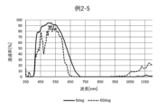
- FIG. 8 is a diagram showing the spectral transmittance curve of the optical filter of Example 2-5.
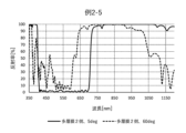
- FIG. 9 is a diagram showing the spectral reflectance curve of the optical filter of Example 2-5.
- NIR dyes near-infrared absorbing dyes
- UV dyes ultraviolet absorbing dyes
- the compound represented by formula (I) is referred to as compound (I).
- the dye composed of compound (I) is also referred to as dye (I), and the same applies to other dyes.
- the group represented by formula (I) is also referred to as group (I), and the same applies to groups represented by other formulas.
- internal transmittance refers to the ratio of measured transmittance to interface reflection, which is expressed by the formula ⁇ actually measured transmittance (incident angle 0 degrees)/(100-reflectance (incident angle 5 degrees)) ⁇ 100. This is the transmittance obtained by subtracting the influence.
- a transmittance of 90% or more means that the transmittance is not less than 90% in the entire wavelength range, that is, the minimum transmittance is 90% or more in that wavelength range. means.
- a transmittance of 1% or less means that the transmittance does not exceed 1% in the entire wavelength range, that is, the maximum transmittance in that wavelength range is 1% or less.
- the average transmittance and average internal transmittance in a specific wavelength range are the arithmetic averages of the transmittance and internal transmittance for every 1 nm in the wavelength range. Spectral properties can be measured using a UV-visible spectrophotometer.
- the optical filter according to this embodiment includes a dielectric multilayer film 1, a resin film, phosphate glass, and a dielectric multilayer film 2 in this order.
- the resin film includes a resin and a near-infrared absorbing dye having a maximum absorption wavelength of 690 to 800 nm in the resin, and the thickness of the resin film is 10 ⁇ m or less.
- the reflection properties of the dielectric multilayer film and the absorption properties of phosphate glass, which is a near-infrared absorption glass, and near-infrared absorption dyes allow the optical filter as a whole to have excellent transmittance in the visible light region and excellent transparency in the near-infrared light region. Can achieve shielding properties.
- FIG. 1 is a cross-sectional view schematically showing an example of an optical filter according to an embodiment.
- the optical filter 1 shown in FIG. 1 includes a dielectric multilayer film A1, a resin film 12, a phosphate glass 11, and a dielectric multilayer film A2 in this order.
- the optical filter according to this embodiment satisfies all of the following spectral characteristics (i-1) to (i-5).
- i-3 At a wavelength of 500 to 700 nm, the wavelength at which the transmittance is 50% at an incident angle of 0 degrees IR 50 (0 deg) is in the wavelength range of 600 to 660 nm.
- the optical filter according to this embodiment which satisfies all of the spectral properties (i-1) to (i-5), has particularly high visible light transmittance as shown in property (i-1), and property (i-4). ) to (i-5), it has particularly high shielding properties for near-infrared light with a wavelength of 900 to 1000 nm. Furthermore, as shown in characteristics (i-1) and (i-2), the transmittance in the visible light region does not decrease even at a high incident angle, and ripples in the visible light region are suppressed.
- Satisfying the spectral characteristic (i-1) means having excellent transparency in the visible light region of 430 to 550 nm. Satisfying the spectral characteristic (i-2) means that the material has excellent transmittance in the visible light region of 430 to 550 nm even at a high incident angle.
- the average transmittance T 430-550 (0 deg) AVE is preferably 85% or more, more preferably 90% or more.
- the average transmittance T 430-550 (60 deg) AVE is preferably 81% or more, more preferably 83% or more.
- Spectral characteristics (i-1) and spectral characteristics (i-2) include, for example, using a dielectric multilayer film with low reflectance in the visible light region, near-infrared absorbing dyes with high transmittance in the visible light region, and phosphoric acid. This can be achieved by using glass.
- the wavelength IR 50 (0 deg) is preferably between 610 and 650 nm, more preferably between 615 and 640 nm.
- Satisfying the spectral characteristic (i-4) means that the material has excellent light shielding properties in the near-infrared light region of 900 to 1000 nm. Satisfying the spectral characteristic (i-5) means that the material has excellent light-shielding properties in the near-infrared light region of 900 to 1000 nm even at a high incident angle.
- the number n at which the transmittance T n (0deg) is 0.04% or less is preferably 30 or more, more preferably 40 or more.
- the number n at which the transmittance T n (40 degrees) is 0.04% or less is preferably 30 or more, more preferably 40 or more.
- Spectral characteristics (i-4) and spectral characteristics (i-5) can be achieved, for example, by using a dielectric multilayer film having reflective characteristics in the wavelength range of 900 to 1000 nm.
- the optical filter according to this embodiment preferably further satisfies the following spectral characteristics (i-6) to (i-7).
- spectral characteristics (i-6) Average transmittance T at wavelength 750-1200 nm, incident angle 0 degrees 750-1200 (0 deg) AVE is 2% or less
- i-7) Average transmittance at wavelength 750-1200 nm, incident angle 40 degrees T 750-1200 (40deg) AVE is 2% or less Satisfying the spectral characteristics (i-6) means that it has excellent light shielding properties in the near-infrared light region of 750 to 1200 nm.
- spectral characteristic (i-7) means that the material has excellent light-shielding properties in the near-infrared light region of 750 to 1200 nm even at a high incident angle.
- the average transmittance T 750-1200 (0 deg) AVE is more preferably 1.5% or less, even more preferably 0.8% or less.
- the average transmittance T 750-1200 (40 deg) AVE is more preferably 1% or less, even more preferably 0.5% or less.
- Spectral characteristics (i-6) and spectral characteristics (i-7) are obtained by combining, for example, the absorption characteristics of near-infrared absorbing dyes and phosphate glass, and the reflection characteristics of a dielectric multilayer film that reflects near-infrared light. This can be achieved by blocking a wide range of light.
- the optical filter according to this embodiment preferably further satisfies the following spectral characteristics (i-8) to (i-9).
- i-8) When reading the transmittance T n (0deg) (n: any integer) of each wavelength from the wavelength 900 nm to the wavelength 1000 nm at 1 nm intervals at an incident angle of 0 degrees, the transmittance T There are 20 or more n such that n(0deg) is 0.01% or less (i-9) From wavelength 900nm to wavelength 1000nm, the transmittance T n(40deg) of each wavelength is ) (n: any integer), there are 20 or more n such that the transmittance T n (40deg) is 0.01% or less Satisfying the spectral characteristic (i-8) is 900 ⁇ This means that it has excellent light shielding properties in the near-infrared light region of 1000 nm.
- spectral characteristic (i-9) means that the material has excellent light-shielding properties in the near-infrared light region of 900 to 1000 nm even at a high incident angle.
- the number n at which the transmittance T n (0deg) is 0.01% or less is preferably 30 or more, more preferably 40 or more.
- the number n at which the transmittance T n (40 degrees) is 0.01% or less is preferably 25 or more, more preferably 30 or more.
- Spectral characteristics (i-8) and spectral characteristics (i-9) can be achieved, for example, by using a dielectric multilayer film having reflective characteristics in the wavelength range of 900 to 1000 nm.
- the optical filter according to this embodiment preferably further satisfies the following spectral characteristics (i-10) to (i-11).
- spectral characteristics i-10) to (i-11).
- the absolute value of the difference between the average transmittance T 430-550 (0deg) AVE and the average transmittance T 430-550 (60deg) AVE is 10% or less (i-11)
- Wavelength 430-550 nm Spectral characteristics ( Satisfying i-10) and spectral characteristics (i-11) means that changes in visible light transmittance are small even at high incident angles, and ripples are reduced.
- the absolute value of the difference between the average transmittance T 430-550 (0deg) AVE and the average transmittance T 430-550 (60deg) AVE is more preferably 9% or less, and even more preferably 8% or less.
- the absolute value of the difference between the maximum transmittance T 430-550 (0deg) MAX and the maximum transmittance T 430-550 (60deg) MAX is more preferably 9% or less, and even more preferably 8% or less.
- Spectral characteristics (i-10) and spectral characteristics (i-11) include, for example, using a dielectric multilayer film with low reflectance in the visible light region, near-infrared absorbing dyes with high transmittance in the visible light region, and phosphate glass. This can be achieved by using
- the optical filter according to this embodiment preferably further satisfies the following spectral characteristics (i-12) to (i-17).
- i-12 When the dielectric multilayer film 2 side is the incident direction, the average reflectance R2 at a wavelength of 430-550 nm and an incident angle of 5 degrees is 430-550 (5 degrees) AVE is 10% or less (i-13)
- the average reflectance R2 at a wavelength of 430 to 550 nm and an incident angle of 60 degrees is 430-550 (60 degrees)
- AVE is 10% or less
- Maximum reflectance R2 430-550 (5deg) MAX is 15% or less (i-15) when the dielectric multilayer film 2 side is the incident direction at a wavelength of 430 to 550 nm and an incident angle of 5 degrees.
- the maximum reflectance R2 430-550 (60 deg) MAX is 15% or less (i-16)
- each wavelength is When the reflectance R2 n (40deg) (n: any integer) is read, there are 25 or more n for which the reflectance R2 n (40deg) is 95% or more.
- Satisfying spectral characteristics (i-12) to spectral characteristics (i-15) means that the reflectance in the visible light region is small even at a high incident angle, and the reflection ripple is small.
- the average reflectance R2 430-550 (5 deg) AVE is more preferably 5% or less, even more preferably 3% or less.
- the average reflectance R2 430-550 (60 deg) AVE is more preferably 9.5% or less, even more preferably 9% or less.
- the maximum reflectance R2 430-550 (5 deg) MAX is more preferably 10% or less, even more preferably 5% or less.
- the maximum reflectance R2 430-550 (60 deg) MAX is more preferably 13% or less, even more preferably 10% or less.
- Spectral characteristics (i-12) to (i-15) can be achieved, for example, by using the dielectric multilayer film 2 that has a low reflectance in the visible light region.
- Satisfying spectral characteristics (i-16) and spectral characteristics (i-17) means that near-infrared light in the wavelength range of 900 to 1000 nm is blocked by reflection characteristics.
- the number n for which the reflectance R2 n (5deg) is 95% or more is more preferably 40 or more, still more preferably 50 or more.
- the number n for which the reflectance R2 n (40 degrees) is 95% or more is more preferably 30 or more, still more preferably 40 or more.
- the spectral characteristics (i-16) and spectral characteristics (i-17) can be achieved, for example, by using the dielectric multilayer film 2 that has a high reflectance in the wavelength range of 900 to 1000 nm.
- the optical filter according to this embodiment preferably further satisfies the following spectral characteristics (i-18) to (i-19).
- spectral characteristics i-18
- i-18 When the dielectric multilayer film 2 side is the incident direction, average reflectance R2 430-550 (5 deg) AVE at wavelength 430-550 nm and incident angle of 5 degrees and average at incident angle of 60 degrees Reflectance R2 430-550 (60deg)
- the absolute value of the difference from AVE is 10% or less
- the wavelength is 430-550nm and the incident angle is 5 degrees.
- the absolute value of the difference between the maximum reflectance R2 430-550 (5deg) MAX and the maximum reflectance R2 430-550 (60deg) MAX at an incident angle of 60 degrees is 10% or less
- spectral characteristics (i-18) and spectral characteristics (i-19) means that even at a high incident angle, the reflectance change in the visible light region is small and the reflection ripple is small.
- the absolute value of the difference between the average reflectance R2 430-550 (5deg) AVE and the average reflectance R2 430-550 (60deg) AVE is more preferably 9% or less, and even more preferably 8% or less.
- the absolute value of the difference between the maximum reflectance R2 430-550 (5deg) MAX and the maximum reflectance R2 430-550 (60deg) MAX is more preferably 9% or less, and even more preferably 8% or less.
- the spectral characteristics (i-18) and spectral characteristics (i-19) can be achieved, for example, by using the dielectric multilayer film 2 having a low reflectance in the visible light region.
- the optical filter according to this embodiment preferably further satisfies the following spectral characteristic (i-20).
- i-20 When the dielectric multilayer film 2 side is the incident direction, the reflectance of each wavelength is R2 n(5deg) (n: When reading an arbitrary integer), there are 30 or more n for which the reflectance R2 n (5deg) is 98% or more.
- spectral characteristic (i-20) means that near-infrared light in the wavelength range of 900 to 1000 nm is blocked by reflection characteristics.
- the number n for which the reflectance R2 n (5deg) is 98% or more is more preferably 40 or more, still more preferably 50 or more.
- the spectral characteristics (i-20) can be achieved, for example, by using the dielectric multilayer film 2 that has a high reflectance in the wavelength range of 900 to 1000 nm.
- the dielectric multilayer film 1 is laminated on the resin film side, and the dielectric multilayer film 2 is laminated on the phosphate glass side.
- the near-infrared light region with a wavelength of 900 to 1000 nm is produced by the dielectric multilayer film 2.
- the dielectric multilayer film 2 Preferably, light is blocked by reflective properties.
- dielectric multilayer films designed to reflect a wide range of near-infrared light are easily affected by the angle of incidence, it is preferable to specialize in the near-infrared light region for improving reflection characteristics in the wavelength range of 900 to 1000 nm. .
- the dielectric multilayer film 2 preferably has low reflection characteristics in the visible light region. This makes it possible to obtain an optical filter whose spectral characteristics in the visible light region are less likely to change depending on the angle of incidence, and whose ripples are reduced. From the above, it is preferable that the dielectric multilayer film 2 is designed as a reflective layer that reflects near-infrared light of 900 to 1000 nm.
- the dielectric multilayer film 1 is preferably designed as an antireflection layer.
- the dielectric multilayer film 1 and the dielectric multilayer film 2 are composed of, for example, a dielectric multilayer film in which dielectric films having different refractive indexes are laminated. More specifically, examples include a dielectric film with a low refractive index (low refractive index film), a dielectric film with a medium refractive index (medium refractive index film), and a dielectric film with a high refractive index (high refractive index film). , is composed of a dielectric multilayer film in which two or more of these are laminated.
- the high refractive index film preferably has a refractive index of 1.6 or more at a wavelength of 500 nm, more preferably 1.8 to 2.5, particularly preferably 2.2 to 2.5.
- Examples of the material for the high refractive index film include Ta 2 O 5 , TiO 2 , TiO, and Nb 2 O 5 .
- Other commercially available products are manufactured by Canon Optron, OS50 (Ti 3 O 5 ), OS10 (Ti 4 O 7 ), OA500 (mixture of Ta 2 O 5 and ZrO 2 ), OA600 (mixture of Ta 2 O 5 and TiO 2 ). Examples include. Among these, TiO 2 is preferred in terms of film formability, reproducibility in refractive index, stability, and the like.
- the medium refractive index film preferably has a refractive index of 1.6 or more and less than 2.2 at a wavelength of 500 nm.
- Materials for the medium refractive index film include, for example, ZrO 2 , Nb 2 O 5 , Al 2 O 3 , HfO 2 , and OM-4 and OM-6 (Al 2 O 3 and ZrO 2 OA-100, H4 sold by Merck, M2 (alumina lanthania), etc.
- Al 2 O 3 -based compounds and mixtures of Al 2 O 3 and ZrO 2 are preferred from the viewpoint of film formability, reproducibility in refractive index, stability, and the like.
- the low refractive index film preferably has a refractive index of less than 1.6 at a wavelength of 500 nm, more preferably 1.38 to 1.5.
- Examples of the material of the low refractive index film include SiO 2 , SiO x N y, MgF 2 and the like.
- Other commercially available products include S4F and S5F (mixture of SiO 2 and Al 2 O 3 ) manufactured by Canon Optron. Among these, SiO 2 is preferred from the viewpoint of reproducibility in film formation, stability, economic efficiency, and the like.
- At least one of the dielectric multilayer film 1 and the dielectric multilayer film 2 has the following formula: [total QWOT of dielectric films with a relatively high refractive index T(H)]/[QWOT of dielectric films with a relatively low refractive index]
- the sum T(L)] is preferably 1.6 or more.
- QWOT Quality of the Wave Optical Thickness
- QWOT Physical film thickness/center wavelength (500nm) x 4 x refractive index at wavelength 500nm
- the total QWOT T(H) is the total QWOT of the high refractive index films
- the total QWOT T(L) is This is the total QWOT of low refractive index films.
- the total QWOT T(H) is the sum of the QWOT of the medium refractive index films
- the total QWOT T(L ) is the total QWOT of the low refractive index film.
- the total QWOT T(H) is the total QWOT of the high refractive index films
- the total QWOT T(L) is This is the total QWOT of medium refractive index films.
- At least one of the dielectric multilayer film 1 and the dielectric multilayer film 2 is preferably a multilayer film in which ten or more H 2 layers and M 2 layers defined below are alternately laminated.
- H2 layer A single layer with a refractive index of 1.8 or more and 2.5 or less, and a QWOT of 1.1 or more and 3.5 or less.
- M2 layer Exists between two H2 layers, with a total QWOT of 1.2 Single layer or multiple layers with a thickness of 1.8 or more
- the above-mentioned specific laminated structure is a structure in which ten or more single layers ( H2 layers) with large refractive index and optical film thickness and layers ( M2 layers) whose total optical film thickness is within a predetermined range are laminated alternately. It is. With such a structure, it is easy to obtain a dielectric multilayer film that reflects near-infrared light with a wavelength of 900 to 1000 nm and has a low reflectance for visible light.
- the M2 layer may be a single layer or multiple layers as long as it satisfies a predetermined optical thickness, but from the viewpoint of obtaining smoother spectral characteristics, it may be composed of multiple layers.
- the minimum thickness of the single layer is preferably 5 nm or more, more preferably 10 nm or more.
- the refractive index of the dielectric film constituting the M2 layer is preferably the same as the refractive index of the H2 layer or lower than the refractive index of the H2 layer.
- the dielectric multilayer film 2 has the above-mentioned specific laminated structure.
- the layer closest to the phosphate glass is the H2 layer among the H2 layer and the M2 layer.
- the H2 layer closest to the phosphate glass may be directly laminated to the phosphate glass, or the H2 layer closest to the phosphate glass and the M2 layer may be laminated between the H2 layer closest to the phosphate glass and the phosphate glass.
- the total number of dielectric multilayer films is preferably 10 or more, more preferably 20 or more, and even more preferably 30 or more. However, if the total number of laminated layers increases, warping or the like may occur or the film thickness will increase, so the total number of laminated layers is preferably 110 or less, more preferably 80 or less, and even more preferably 60 or less. Further, the overall film thickness (physical film thickness) of the dielectric multilayer film 2 is preferably 1 to 6 ⁇ m.
- the dielectric multilayer film 1 When an optical filter is mounted on an imaging device, the dielectric multilayer film 1 is usually placed on the sensor side, so it is preferable that the dielectric multilayer film 1 is designed as an antireflection layer.
- the total number of laminated layers of the dielectric multilayer film 1 is preferably 40 or less, more preferably 30 or less, even more preferably 20 or less, and preferably 6 or more.
- the overall film thickness (physical film thickness) of the dielectric multilayer film 1 is preferably 0.2 to 1.0 ⁇ m.
- a vacuum film-forming process such as a CVD method, a sputtering method, or a vacuum evaporation method, or a wet film-forming process such as a spray method or a dip method can be used.
- each dielectric multilayer film may have the same structure or different structures.
- the dielectric multilayer film 2 laminated on the glass surface is usually placed on the lens side, and the dielectric multilayer film 1 laminated on the resin film surface is placed on the sensor side.
- the phosphate glass in the optical filter of the present invention functions as an infrared absorbing glass.
- the phosphate glass preferably satisfies all of the following spectral properties (ii-1) to (ii-5).
- Satisfying spectral property (ii-1) means having excellent transmittance in the blue light region, and satisfying spectral property (ii-2) means having excellent transmittance in the visible light region from 450 to 600 nm.
- the internal transmittance T 450 is more preferably 93% or more, still more preferably 95% or more.
- the average internal transmittance T 450-600AVE is more preferably 94% or more, still more preferably 95% or more.
- IR50 is more preferably in the range of 625 to 645 nm, even more preferably 625 to 640 nm.
- Satisfying the spectral characteristic (ii-4) means that the material has excellent light shielding properties in the near-infrared region of 750 to 1000 nm.
- the average internal transmittance T 750-1000AVE is more preferably 2% or less, even more preferably 1.2% or less.
- Satisfying the spectral characteristic (ii-5) means that the material has excellent light shielding properties in the infrared region of 1000 to 1200 nm.
- the average internal transmittance T 1000-1200AVE is more preferably 2.3% or less, even more preferably 2.2% or less.
- phosphate glass begins to absorb near-infrared light in the region of 625 to 650 nm, and as shown in property (ii-4) above, it has high light-shielding properties after 750 nm. It is preferable to indicate. Thereby, the light-shielding property of the dielectric multilayer film described above can be supplemented.
- the phosphate glass preferably contains copper ions.
- copper ions that absorb light with a wavelength of around 900 nm, near-infrared light with a wavelength of 700 to 1200 nm can be blocked.
- phosphoric acid glass also includes silicophosphoric acid glass in which a part of the glass skeleton is composed of SiO 2 .
- the phosphate glass contains the following glass components.
- each content ratio of the following glass constituent components is expressed as mass % in terms of oxide.
- P 2 O 5 is a main component forming glass, and is an essential component for improving near-infrared ray cutting properties. If the P 2 O 5 content is 40% or more, the effect can be sufficiently obtained, and if it is 80% or less, problems such as glass becoming unstable and weather resistance decreasing are unlikely to occur. Therefore, it is preferably 40 to 80%, more preferably 52 to 78%, still more preferably 54 to 77%, even more preferably 56 to 76%, and most preferably 60 to 75%. be.
- Al 2 O 3 is a main component forming glass, and is a component for increasing the strength of glass and weather resistance of glass. If the Al 2 O 3 content is 0.5% or more, the effect can be sufficiently obtained, and if it is 20% or less, problems such as the glass becoming unstable and the near-infrared cut property decreasing occur. Hateful. Therefore, it is preferably 0.5 to 20%, more preferably 1.0 to 20%, even more preferably 2.0 to 18%, even more preferably 3.0 to 17%, Particularly preferably 4.0 to 16%, most preferably 5.0 to 15.5%.
- R 2 O (wherein R 2 O is one or more components selected from Li 2 O, Na 2 O, K 2 O, Rb 2 O, and Cs 2 O) lowers the melting temperature of the glass. It is a component that lowers the liquidus temperature of glass and stabilizes glass. If the total amount of R 2 O ( ⁇ R 2 O) is 0.5% or more, the effect can be sufficiently obtained, and if it is 20% or less, the glass is less likely to become unstable, which is preferable. Therefore, it is preferably 0.5 to 20%, more preferably 1 to 19%, even more preferably 1.5 to 18%, even more preferably 2.0 to 17%, and particularly preferably is between 2.5 and 16%, most preferably between 3.0 and 15.5%.
- Li 2 O is a component for lowering the melting temperature of glass, lowering the liquidus temperature of glass, and stabilizing glass.
- the content of Li 2 O is preferably 0 to 15%. It is preferable that the Li 2 O content is 15% or less because problems such as the glass becoming unstable and the near-infrared cut property being lowered are less likely to occur. More preferably 0 to 8%, still more preferably 0 to 7%, even more preferably 0 to 6%, and most preferably 0 to 5%.
- Na 2 O is a component for lowering the melting temperature of glass, lowering the liquidus temperature of glass, and stabilizing glass.
- the content of Na 2 O is preferably 0 to 15%. It is preferable that the Na 2 O content is 15% or less because the glass is less likely to become unstable. More preferably, it is 0.5 to 14%, still more preferably 1 to 13%, even more preferably 2 to 13%, and most preferably 3 to 13%.
- K 2 O is a component that has effects such as lowering the melting temperature of glass and lowering the liquidus temperature of glass.
- the content of K 2 O is preferably 0 to 20%. It is preferable that the content of K 2 O is 20% or less because the glass is less likely to become unstable. More preferably 0.5 to 19%, still more preferably 1 to 18%, even more preferably 2 to 17%, and most preferably 3 to 16%.
- Rb 2 O is a component that has effects such as lowering the melting temperature of glass and lowering the liquidus temperature of glass.
- the content of Rb 2 O is preferably 0 to 15%. It is preferable that the Rb 2 O content is 15% or less because the glass is less likely to become unstable. More preferably, it is 0.5 to 14%, still more preferably 1 to 13%, even more preferably 2 to 13%, and most preferably 3 to 13%.
- Cs 2 O is a component that has effects such as lowering the melting temperature of glass and lowering the liquidus temperature of glass.
- the content of Cs 2 O is preferably 0 to 15%. It is preferable that the Cs 2 O content is 15% or less because the glass is less likely to become unstable. More preferably, it is 0.5 to 14%, still more preferably 1 to 13%, even more preferably 2 to 13%, and most preferably 3 to 13%.
- the glass of this embodiment preferably contains two or more components selected from Li 2 O, Na 2 O, K 2 O, Rb 2 O, and Cs 2 O.
- the total amount ( ⁇ R 2 O) of R 2 O (where R 2 O is Li 2 O, Na 2 O, K 2 O, Rb 2 O, and Cs 2 O) is 7 to 18 %. (however, it does not contain 7%) is preferable. If the total amount of R 2 O is more than 7%, the effect will be sufficiently obtained, and if it is less than 18%, the glass will become unstable, the near-infrared cut property will decrease, the strength of the glass will decrease, etc. This is preferable because it is less likely to cause problems. Therefore, ⁇ R 2 O is preferably more than 7% and less than 18%, more preferably 7.5% to 17%, still more preferably 8% to 16%, even more preferably 8.5% to 15%. %, most preferably 9-14%.
- R'O (where R'O is one or more components selected from CaO, MgO, BaO, SrO, and ZnO) lowers the melting temperature of glass, lowers the liquidus temperature of glass, and improves glass. It is a component used to stabilize and increase the strength of glass.
- the total amount of R'O ( ⁇ R'O) is preferably 0 to 40%. It is preferable that the total amount of R'O is 40% or less because problems such as the glass becoming unstable, the near-infrared cut property decreasing, and the strength of the glass decreasing are unlikely to occur. More preferably 0 to 35%, still more preferably 0 to 30%, even more preferably 0 to 25%, particularly preferably 0 to 20%, and most preferably 0 to 15%. .
- CaO is a component that lowers the melting temperature of glass, lowers the liquidus temperature of glass, stabilizes glass, and increases the strength of glass.
- the content of CaO is preferably 0 to 10%. It is preferable that the CaO content is 10% or less because problems such as the glass becoming unstable and the near-infrared cut property being lowered are less likely to occur. More preferably, it is 0 to 8%, still more preferably 0 to 6%, even more preferably 0 to 5%, and most preferably 0 to 4%.
- MgO is a component that lowers the melting temperature of glass, lowers the liquidus temperature of glass, stabilizes glass, and increases the strength of glass.
- the content of MgO is preferably 0 to 15%. It is preferable that the MgO content is 15% or less because problems such as the glass becoming unstable and the near-infrared cut property being lowered are less likely to occur. More preferably 0 to 13%, still more preferably 0 to 10%, even more preferably 0 to 9%, and most preferably 0 to 8%.
- BaO is a component for lowering the melting temperature of glass, lowering the liquidus temperature of glass, and stabilizing glass.
- the BaO content is preferably 0 to 40%. It is preferable that the BaO content is 40% or less because problems such as the glass becoming unstable and the near-infrared cut property being lowered are less likely to occur. More preferably 0 to 30%, still more preferably 0 to 20%, even more preferably 0 to 10%, and most preferably 0 to 5%.
- SrO is a component for lowering the melting temperature of glass, lowering the liquidus temperature of glass, and stabilizing glass.
- the content of SrO is preferably 0 to 10%. It is preferable that the SrO content is 10% or less, since problems such as glass becoming unstable and near-infrared cut-off properties are less likely to occur. More preferably, it is 0 to 8%, still more preferably 0 to 7%, and most preferably 0 to 6%.
- ZnO has effects such as lowering the melting temperature of glass and lowering the liquidus temperature of glass.
- the content of ZnO is preferably 0 to 15%. If the content of ZnO is 15% or less, problems such as the glass becoming unstable, the solubility of the glass deteriorating, and the near-infrared cut property decreasing are less likely to occur, so it is preferable. More preferably 0 to 13%, still more preferably 0 to 10%, even more preferably 0 to 9%, and most preferably 0 to 8%.
- CuO is a component for cutting near infrared rays. If the content of CuO is 0.5% or more, the effect of increasing the light transmittance in the visible region of the glass obtained when containing MoO 3 , which will be described later, can be sufficiently obtained, and if the content of CuO is 40% or less, If it exists, it is preferable because problems such as generation of devitrification foreign matter in the glass and decrease in transmittance of light in the visible region are less likely to occur. More preferably 1.0 to 35%, still more preferably 1.5 to 30%, even more preferably 2.0 to 25%, most preferably 2.5 to 20%.
- MoO 3 is a component for increasing the transmittance of light in the visible region of glass, and is preferably contained together with CuO.
- the inventor created a phosphate glass containing Cu (but does not contain a fluorine component) and a phosphate glass that additionally contains only Mo, and confirmed the optical properties thereof. As a result, it was confirmed that the latter glass significantly increases the transmittance of light in the wavelength range of 400 nm to 540 nm compared to the former glass. Although this phenomenon is hypothetical, it is thought to be due to the following. Mo is known to exist as Mo 6+ (hexavalent) in glass.
- the content of MoO 3 is 0.01% or more, the effect of increasing the transmittance of light in the visible region of the glass can be sufficiently obtained, and if the content is 10% or less, the near-infrared cutting property decreases. This is preferable because problems such as generation of devitrification foreign matter in the glass are less likely to occur. More preferably 0.02 to 9%, still more preferably 0.03 to 8%, even more preferably 0.04 to 7%, most preferably 0.05 to 6%.
- F may be contained in a range of 10% or less in order to improve weather resistance. If the content of F is 10% or less, problems such as a decrease in near-infrared cutting properties and generation of devitrification foreign matter in the glass are less likely to occur, so it is preferable. It is more preferably 9% or less, still more preferably 8% or less, even more preferably 7% or less, particularly preferably 6% or less, and most preferably 5% or less.
- B 2 O 3 may be contained in a range of 10% or less in order to stabilize the glass. If the content of B 2 O 3 is 10% or less, problems such as deterioration of the weather resistance of the glass and deterioration of the near-infrared cut property are less likely to occur, so it is preferable. Preferably it is 9% or less, more preferably 8% or less, still more preferably 7% or less, even more preferably 6% or less, and most preferably 5% or less.
- SiO2 , GeO2 , ZrO2, SnO2 , TiO2 , CeO2 , WO3 , Y2O3 , La2O3 , Gd2O3 , Yb2O3 , Nb2O5 may be contained in a range of 5% or less in order to improve the weather resistance of the glass. If the content of these components is 5% or less, problems such as generation of devitrification foreign matter in the glass and deterioration of near-infrared cut properties are less likely to occur, which is preferable. It is more preferably 4% or less, still more preferably 3% or less, particularly preferably 2% or less, and even more preferably 1% or less.
- Fe 2 O 3 , Cr 2 O 3 , Bi 2 O 3 , NiO, V 2 O 5 , MnO 2 and CoO are all components that reduce the transmittance of light in the visible region when present in glass. be. Therefore, it is preferable that these components are not substantially contained in the glass.
- substantially not containing a specific component means that it is not intentionally added, and does not contain a specific component that is unavoidably mixed in from raw materials etc. and does not affect the intended properties. It is not something to be excluded.
- the thickness of the phosphate glass is preferably 0.5 mm or less, more preferably 0.3 mm or less, from the viewpoint of reducing the height of the camera module, and preferably 0.10 mm or more, more preferably, from the viewpoint of maintaining element strength. is 0.15 mm or more.
- Phosphate glass can be produced, for example, as follows. First, raw materials are weighed and mixed so that the composition falls within the above composition range (mixing step). This raw material mixture is placed in a platinum crucible and heated and melted at a temperature of 700 to 1400°C in an electric furnace (melting step). After sufficient stirring and clarification, it is poured into a mold, cut and polished, and formed into a flat plate with a predetermined thickness (molding process).
- the highest temperature of the glass during glass melting is 1400°C or less. If the highest temperature of the glass during glass melting exceeds the above temperature, the transmittance characteristics may deteriorate.
- the above temperature is more preferably 1350°C or lower, still more preferably 1300°C or lower, even more preferably 1250°C or lower.
- the temperature in the above melting step is too low, problems such as devitrification occurring during melting and a long time required for melting through may occur, so it is preferably 700°C or higher, more preferably 800°C or higher. It is.
- the resin film in the optical filter of the present invention includes a resin and a near-infrared absorbing dye having a maximum absorption wavelength in the range of 690 to 800 nm in the resin.
- the resin refers to the resin that constitutes the resin film.
- the resin film preferably satisfies all of the following spectral characteristics (iii-1) to (iii-3).
- (iii-1) Internal transmittance T 450 at wavelength 450 nm is 85% or more
- (iii-2) Average internal transmittance T 450-600AVE at wavelength 450-600 nm is 90% or more
- (iii-3) Internal transmittance is 50%
- the wavelength IR50 is in the range of 620 to 750 nm.
- Satisfying spectral characteristic (iii-1) means having excellent transparency in the blue light region.
- the internal transmittance T 450 is more preferably 95% or more, still more preferably 98% or more.
- Satisfying the spectral characteristic (iii-2) means having excellent transparency in the visible light region of 450 to 600 nm.
- the average internal transmittance T 450-600AVE is more preferably 92% or more, even more preferably 94% or more.
- Satisfying spectral characteristic (iii-3) means that visible transmitted light can be efficiently taken in while blocking light in the near-infrared region.
- the wavelength IR50 is more preferably in the range of 625 to 645 nm, even more preferably 625 to 640 nm.
- the resin film of the present invention can block light in the near-infrared light region around 700 nm, where phosphoric acid glass has a rather weak light-blocking property, due to the absorption properties of the dye.
- Examples of near-infrared absorbing dyes include at least one selected from the group consisting of cyanine dyes, phthalocyanine dyes, squarylium dyes, naphthalocyanine dyes, and diimonium dyes, which can be used alone or in combination. Among them, squarylium dyes and cyanine dyes are preferable from the viewpoint that the effects of the present invention are easily exhibited.
- the content of the near-infrared absorbing dye in the resin film is preferably 0.1 to 30 parts by weight, more preferably 0.1 to 20 parts by weight, based on 100 parts by weight of the resin. Note that when two or more types of compounds are combined, the above content is the sum of each compound.
- the resin film may contain other dyes, such as ultraviolet light absorbing dyes, as long as the effects of the present invention are not impaired.
- ultraviolet light absorbing dyes include oxazole dyes, merocyanine dyes, cyanine dyes, naphthalimide dyes, oxadiazole dyes, oxazine dyes, oxazolidine dyes, naphthalic acid dyes, styryl dyes, anthracene dyes, cyclic carbonyl dyes, triazole dyes, etc. It will be done. Among these, merocyanine dyes are particularly preferred. Moreover, one type may be used alone, or two or more types may be used in combination.
- the resin is not limited as long as it is a transparent resin, and examples include polyester resin, acrylic resin, epoxy resin, ene-thiol resin, polycarbonate resin, polyether resin, polyarylate resin, polysulfone resin, polyethersulfone resin, and polyparaphenylene.
- One or more transparent resins selected from resins, polyarylene ether phosphine oxide resins, polyamide resins, polyimide resins, polyamideimide resins, polyolefin resins, cyclic olefin resins, polyurethane resins, polystyrene resins, and the like are used. These resins may be used alone or in combination of two or more. From the viewpoint of the spectral characteristics, glass transition point (Tg), and adhesion of the resin film, one or more resins selected from polyimide resins, polycarbonate resins, polyester resins, and acrylic resins are preferred.
- these may be contained in the same resin film, or may be contained in separate resin films.
- a resin film is produced by preparing a coating solution by dissolving or dispersing the pigment, resin or raw material components of the resin, and each component added as necessary in a solvent, and coating this on a support and drying it. It can be further formed by hardening as needed.
- the support at this time may be the phosphate glass used in this filter, or may be a removable support used only when forming the resin film.
- the solvent may be any dispersion medium that can be stably dispersed or a solvent that can be dissolved.
- the coating liquid may also contain a surfactant to improve voids caused by microbubbles, dents caused by adhesion of foreign substances, and repellency during the drying process.
- a dip coating method, a cast coating method, a spin coating method, or the like can be used for applying the coating liquid.
- a resin film is formed by coating the above coating liquid onto a support and then drying it.
- a curing treatment such as thermal curing or photocuring is further performed.
- the resin membrane can also be manufactured into a film shape by extrusion molding.
- a base material can be manufactured by laminating the obtained film-like resin membrane on phosphate glass and integrating it by thermocompression bonding or the like.
- the optical filter may have one layer of resin film, or may have two or more layers of the resin film. When having two or more layers, each layer may have the same or different configurations.
- the thickness of the resin film is 10 ⁇ m or less, preferably 5 ⁇ m or less from the viewpoint of in-plane film thickness distribution within the substrate after coating and appearance quality, and from the viewpoint of expressing desired spectral characteristics with appropriate dye concentration. It is preferably 0.5 ⁇ m or more.
- the total thickness of each resin film is within the above range.
- the optical filter according to the present embodiment may include other components, such as components (layers) that provide absorption by inorganic fine particles or the like that control transmission and absorption of light in a specific wavelength range.
- the inorganic fine particles include ITO (Indium Tin Oxides), ATO (Antimony-doped Tin Oxides), cesium tungstate, lanthanum boride, and the like.
- ITO fine particles and cesium tungstate fine particles have high visible light transmittance and light absorption over a wide range of infrared wavelengths exceeding 1200 nm, so they can be used when such infrared light shielding properties are required. .
- the optical filter according to this embodiment when used in an imaging device such as a digital still camera, it can provide an imaging device with excellent color reproducibility.
- an imaging device includes a solid-state imaging device, an imaging lens, and an optical filter according to this embodiment.
- the optical filter according to this embodiment is used, for example, by being placed between an imaging lens and a solid-state imaging device, or by being directly attached to a solid-state imaging device, imaging lens, etc. of an imaging device via an adhesive layer. can.
- An optical filter comprising a dielectric multilayer film 1, a resin film, phosphate glass, and a dielectric multilayer film 2 in this order,
- the resin film includes a resin and a near-infrared absorbing dye having a maximum absorption wavelength in the range of 690 to 800 nm in the resin,
- the resin film has a thickness of 10 ⁇ m or less,
- the optical filter satisfies all of the following spectral characteristics (i-1) to (i-5).
- the absolute value of the difference between the average transmittance T 430-550 (0deg) AVE and the average transmittance T 430-550 (60deg) AVE is 10% or less (i-11) Wavelength 430-550 nm , the absolute value of the difference between the maximum transmittance T 430-550 (0deg) MAX at an incident angle of 0 degrees and the maximum transmittance T 430-550 (60deg) MAX at an incident angle of 60 degrees is 10% or less [5]
- the optical filter according to any one of [1] to [4], which further satisfies the following spectral characteristics (i-12) to (i-17).
- the maximum reflectance R2 430-550 (60 deg) MAX is 15% or less (i-16)
- the incidence angle of each wavelength is 40 degrees and the wavelength is 1 nm apart from the wavelength 900 nm to the wavelength 1000 nm.
- the reflectance R2 n (40 deg) (n: any integer) is read, there are 25 or more n for which the reflectance R2 n (40 deg) is 95% or more [6]
- the absolute value of the difference between the maximum reflectance R2 430-550 (5deg) MAX and the maximum reflectance R2 430-550 (60deg) MAX at an incident angle of 60 degrees is 10% or less [7]
- the reflectance of each wavelength is R2 n(5deg) (n: [8] At least one of the dielectric multilayer film 1 and the dielectric multilayer film 2 has 30 or more n such that the reflectance R2 n (5deg) is 98% or more when reading an arbitrary integer).
- H2 layer A single layer with a refractive index of 1.8 or more and 2.5 or less, and a QWOT of 1.1 or more and 3.5 or less.
- M2 layer Exists between two H2 layers, with a total QWOT of 1.2 [10] Any one of [1] to [9], wherein the phosphate glass satisfies all of the following spectral properties (ii-1) to (ii-5): The optical filter according to item 1.
- the near-infrared absorbing dye contains a squarylium dye
- the optical filter according to any one of [1] to [11], wherein the resin film satisfies all of the following spectral characteristics (iii-1) to (iii-3).
- (iii-1) Internal transmittance T 450 at wavelength 450 nm is 85% or more
- (iii-2) Average internal transmittance T 450-600AVE at wavelength 450-600 nm is 90% or more
- Internal transmittance is 50% [13]
- An imaging device comprising the optical filter according to any one of [1] to [12], which has a wavelength IR50 in the range of 620 to 750 nm.
- An ultraviolet-visible spectrophotometer manufactured by Hitachi High-Technologies Corporation, model UH-4150 was used to measure each spectral characteristic. Note that, unless the incident angle is specified, the spectral characteristics are values measured at an incident angle of 0° (perpendicular to the main surface of the optical filter).
- the dyes used in each example are as follows.
- Compound 1 squarylium compound
- Compound 2 cyanine compound
- Compound 3 merocyanine compound
- the resulting coating solution was applied to alkali glass (manufactured by SCHOTT, D263 glass, thickness 0.2 mm) by a spin coating method to form a coating film having a thickness of approximately 1.0 ⁇ m.
- the spectral transmittance curve of the obtained coating film in the wavelength range of 350 to 1200 nm was measured using an ultraviolet-visible spectrophotometer.
- the spectral properties of each of the above compounds 1 to 3 in polyimide resin are shown in Table 1 below. Note that the spectral characteristics shown in the table below were evaluated based on internal transmittance in order to avoid the influence of reflection at the air interface and glass interface.
- Phosphate glasses and fluorophosphate glasses having compositions shown in the table below were prepared as near-infrared absorbing glasses. The raw materials were weighed and mixed so as to have the composition (oxidized substance amount %) shown in Table 2 below, placed in a crucible having an internal volume of about 400 cc, and melted in the air for 2 hours.
- the spectral transmittance curve in the wavelength range of 350 to 1200 nm was measured using an ultraviolet-visible spectrophotometer.
- the obtained spectral characteristics are shown in Table 3 below. Note that the spectral characteristics shown in the table below were evaluated based on internal transmittance in order to avoid the influence of reflection at the air interface and glass interface.
- the spectral transmittance curve of phosphate glass is shown in FIG.
- the phosphate glass used has a higher transmittance in the visible light region and excellent light shielding properties in the near-infrared region than fluorophosphate glass.
- Example 1-1 to Example 1-3 Spectral characteristics of resin film> Mix the dyes of Compounds 1 to 3 to a polyimide resin solution prepared in the same manner as when calculating the spectral characteristics of the above compounds at the concentrations listed in Table 4 below, and stir and dissolve at 50 ° C. for 2 hours. A coating solution was obtained. The resulting coating solution was applied to alkali glass (manufactured by SCHOTT, D263 glass, thickness 0.2 mm) by spin coating to form a resin film with a thickness of 3.0 ⁇ m. The spectral transmittance curve of the obtained resin film in the wavelength range of 350 to 1200 nm was measured using an ultraviolet-visible spectrophotometer.
- Example 2-1 Spectral characteristics of optical filter>
- a resin film was formed on one main surface of the phosphate glass in the same manner as in Example 1-1.
- TiO 2 reffractive index at wavelength 500 nm: 2.47) and SiO 2 (refractive index at wavelength 500 nm: 1.48) are laminated by vapor deposition in the order and film thickness (nm) shown in Table 5 below.
- nm film thickness
- TiO 2 and SiO 2 were laminated by vapor deposition in the order and film thickness (nm) shown in Table 5 below to form a dielectric multilayer film 2.
- an optical filter having the configuration of dielectric multilayer film 2 (front surface)/phosphoric acid glass/resin film/dielectric multilayer film 1 (rear surface) was produced.
- Example 2-2 to Example 2-4 Spectral characteristics of optical filter> Optical filters were produced in the same manner as in Example 2-1, except that dielectric multilayer film 1 and dielectric multilayer film 2 were changed to the configurations shown in Table 5 or Table 6 below.
- Example 2-5 to Example 2-6 Spectral characteristics of optical filter> Example 2-1 except that the phosphate glass was changed to fluorophosphate glass 1 or fluorophosphate glass 2, and the resin film, dielectric multilayer film 1, and dielectric multilayer film 2 were changed to the configurations shown in Table 6 below. An optical filter was produced in the same manner.
- a spectral transmittance curve at an incident angle of 0 degrees and 60 degrees and a spectral reflectance curve at an incident angle of 5 degrees in the wavelength range of 350 to 1200 nm were measured using an ultraviolet-visible spectrophotometer.
- the results are shown in Table 7 below.
- the spectral transmittance curve and the spectral reflectance curve of the optical filter of Example 2-1 are shown in FIG. 4 and FIG. 5, respectively.
- the spectral transmittance curve and the spectral reflectance curve of the optical filter of Example 2-3 are shown in FIG. 6 and FIG. 7, respectively.
- the spectral transmittance curve and the spectral reflectance curve of the optical filter of Example 2-5 are shown in FIG. 8 and FIG. 9, respectively.
- Examples 2-1 to 2-3 are examples, and Examples 2-4 to 2-6 are comparative examples.
- the optical filters of Examples 2-1 to 2-3 have high transmittance in the visible light region and high shielding performance in the near-infrared light region, and the visible light transmittance changes even at high incident angles. It can be seen that the filter suppresses ripple generation because it is small.
- the number of wavelengths at which the transmittance is 0.04% or less in the wavelength range of 900 to 1000 nm is 0 at both incident angles of 0 degrees and 40 degrees, and it blocks near-infrared light. The results were low.
- Example 2-5 has a small average transmittance at 60 degrees in the visible light region, and a large difference between the average transmittance at an incident angle of 0 degrees and the average transmittance at 60 degrees, that is, visible light at high incident angles. Transmittance is decreasing.
- Example 2-5 Since the dielectric multilayer film 2 in Example 2-5 has a large reflection characteristic in the near-infrared light region, it is considered that ripples are likely to occur in the visible light region at high incident angles.
- the number of wavelengths at which the transmittance was 0.04% or less in the wavelength range of 900 to 1000 nm was small at an incident angle of 40 degrees. Since Example 2-6 did not use phosphate glass, it is considered that the near-infrared light region could not be sufficiently shielded.
- the optical filter according to this embodiment has excellent visible light transmittance, little change in transmittance in the visible light region even at high incident angles, and excellent spectral characteristics in shielding properties in the near-infrared light region. In recent years, it is useful for use in imaging devices such as cameras and sensors for transportation aircraft, whose performance has been increasing in recent years.
Landscapes
- Physics & Mathematics (AREA)
- General Physics & Mathematics (AREA)
- Optics & Photonics (AREA)
- Chemical & Material Sciences (AREA)
- Organic Chemistry (AREA)
- Health & Medical Sciences (AREA)
- Toxicology (AREA)
- Optical Filters (AREA)
- Laminated Bodies (AREA)
Priority Applications (3)
| Application Number | Priority Date | Filing Date | Title |
|---|---|---|---|
| CN202380062325.XA CN119790330A (zh) | 2022-08-31 | 2023-08-28 | 光学滤波器 |
| JP2024544240A JPWO2024048511A1 (https=) | 2022-08-31 | 2023-08-28 | |
| US19/059,903 US20250189705A1 (en) | 2022-08-31 | 2025-02-21 | Optical filter |
Applications Claiming Priority (2)
| Application Number | Priority Date | Filing Date | Title |
|---|---|---|---|
| JP2022138363 | 2022-08-31 | ||
| JP2022-138363 | 2022-08-31 |
Related Child Applications (1)
| Application Number | Title | Priority Date | Filing Date |
|---|---|---|---|
| US19/059,903 Continuation US20250189705A1 (en) | 2022-08-31 | 2025-02-21 | Optical filter |
Publications (1)
| Publication Number | Publication Date |
|---|---|
| WO2024048511A1 true WO2024048511A1 (ja) | 2024-03-07 |
Family
ID=90099922
Family Applications (1)
| Application Number | Title | Priority Date | Filing Date |
|---|---|---|---|
| PCT/JP2023/030943 Ceased WO2024048511A1 (ja) | 2022-08-31 | 2023-08-28 | 光学フィルタ |
Country Status (5)
| Country | Link |
|---|---|
| US (1) | US20250189705A1 (https=) |
| JP (1) | JPWO2024048511A1 (https=) |
| CN (1) | CN119790330A (https=) |
| TW (1) | TW202424545A (https=) |
| WO (1) | WO2024048511A1 (https=) |
Citations (5)
| Publication number | Priority date | Publication date | Assignee | Title |
|---|---|---|---|---|
| WO2014034386A1 (ja) * | 2012-08-29 | 2014-03-06 | 旭硝子株式会社 | 近赤外線カットフィルタ |
| JP2019066746A (ja) * | 2017-10-03 | 2019-04-25 | 日本板硝子株式会社 | 光学フィルタ及び撮像装置 |
| JP2019066742A (ja) * | 2017-10-03 | 2019-04-25 | 日本板硝子株式会社 | 光学フィルタ及び撮像装置 |
| JP2019144578A (ja) * | 2017-12-07 | 2019-08-29 | 日本板硝子株式会社 | 光学フィルタ及び撮像装置 |
| JP2020158383A (ja) * | 2019-03-22 | 2020-10-01 | 日本電気硝子株式会社 | ガラス板及びその製造方法 |
-
2023
- 2023-08-28 JP JP2024544240A patent/JPWO2024048511A1/ja active Pending
- 2023-08-28 CN CN202380062325.XA patent/CN119790330A/zh active Pending
- 2023-08-28 WO PCT/JP2023/030943 patent/WO2024048511A1/ja not_active Ceased
- 2023-08-30 TW TW112132794A patent/TW202424545A/zh unknown
-
2025
- 2025-02-21 US US19/059,903 patent/US20250189705A1/en active Pending
Patent Citations (5)
| Publication number | Priority date | Publication date | Assignee | Title |
|---|---|---|---|---|
| WO2014034386A1 (ja) * | 2012-08-29 | 2014-03-06 | 旭硝子株式会社 | 近赤外線カットフィルタ |
| JP2019066746A (ja) * | 2017-10-03 | 2019-04-25 | 日本板硝子株式会社 | 光学フィルタ及び撮像装置 |
| JP2019066742A (ja) * | 2017-10-03 | 2019-04-25 | 日本板硝子株式会社 | 光学フィルタ及び撮像装置 |
| JP2019144578A (ja) * | 2017-12-07 | 2019-08-29 | 日本板硝子株式会社 | 光学フィルタ及び撮像装置 |
| JP2020158383A (ja) * | 2019-03-22 | 2020-10-01 | 日本電気硝子株式会社 | ガラス板及びその製造方法 |
Also Published As
| Publication number | Publication date |
|---|---|
| US20250189705A1 (en) | 2025-06-12 |
| CN119790330A (zh) | 2025-04-08 |
| TW202424545A (zh) | 2024-06-16 |
| JPWO2024048511A1 (https=) | 2024-03-07 |
Similar Documents
| Publication | Publication Date | Title |
|---|---|---|
| WO2023008291A1 (ja) | 光学フィルタ | |
| US20260009937A1 (en) | Optical filter | |
| US20250306254A1 (en) | Optical filter | |
| CN118259389A (zh) | 滤光片 | |
| WO2024048510A1 (ja) | 光学フィルタ | |
| WO2024048511A1 (ja) | 光学フィルタ | |
| WO2023210474A1 (ja) | 光学フィルタ | |
| WO2024048512A1 (ja) | 光学フィルタ | |
| WO2024048513A1 (ja) | 光学フィルタ | |
| TWI914287B (zh) | 濾光器 | |
| JP2025094722A (ja) | 光学フィルタ | |
| CN121713099A (zh) | 滤光片 | |
| WO2024237167A1 (ja) | 光学フィルタ | |
| WO2024241897A1 (ja) | 光学フィルタ | |
| CN121713100A (zh) | 滤光片 | |
| TW202613609A (zh) | 濾光器 | |
| JP2025094723A (ja) | 光学フィルタ | |
| JP2025094724A (ja) | 光学フィルタ | |
| CN121713097A (zh) | 滤光片 | |
| WO2023210475A1 (ja) | 光学フィルタ | |
| WO2024143130A1 (ja) | 光学フィルタ |
Legal Events
| Date | Code | Title | Description |
|---|---|---|---|
| 121 | Ep: the epo has been informed by wipo that ep was designated in this application |
Ref document number: 23860273 Country of ref document: EP Kind code of ref document: A1 |
|
| WWE | Wipo information: entry into national phase |
Ref document number: 2024544240 Country of ref document: JP |
|
| WWE | Wipo information: entry into national phase |
Ref document number: 202380062325.X Country of ref document: CN |
|
| NENP | Non-entry into the national phase |
Ref country code: DE |
|
| WWP | Wipo information: published in national office |
Ref document number: 202380062325.X Country of ref document: CN |
|
| 122 | Ep: pct application non-entry in european phase |
Ref document number: 23860273 Country of ref document: EP Kind code of ref document: A1 |