WO2024047690A1 - Dispositif d'identification de position de roue, système d'identification de position de roue et procédé d'identification de position de roue - Google Patents
Dispositif d'identification de position de roue, système d'identification de position de roue et procédé d'identification de position de roue Download PDFInfo
- Publication number
- WO2024047690A1 WO2024047690A1 PCT/JP2022/032361 JP2022032361W WO2024047690A1 WO 2024047690 A1 WO2024047690 A1 WO 2024047690A1 JP 2022032361 W JP2022032361 W JP 2022032361W WO 2024047690 A1 WO2024047690 A1 WO 2024047690A1
- Authority
- WO
- WIPO (PCT)
- Prior art keywords
- wheel
- transmission signal
- transmitter
- front wheel
- control device
- Prior art date
Links
- 238000000034 method Methods 0.000 title claims description 66
- 230000005540 biological transmission Effects 0.000 claims abstract description 168
- 230000001133 acceleration Effects 0.000 description 50
- 230000000712 assembly Effects 0.000 description 37
- 238000000429 assembly Methods 0.000 description 37
- 238000001514 detection method Methods 0.000 description 22
- 230000005856 abnormality Effects 0.000 description 6
- 230000007423 decrease Effects 0.000 description 3
- 230000003247 decreasing effect Effects 0.000 description 3
- 238000004590 computer program Methods 0.000 description 2
- 238000010586 diagram Methods 0.000 description 2
- 230000000694 effects Effects 0.000 description 2
- 238000012544 monitoring process Methods 0.000 description 2
- 241000270281 Coluber constrictor Species 0.000 description 1
- 241001544487 Macromiidae Species 0.000 description 1
- OQZCSNDVOWYALR-UHFFFAOYSA-N flurochloridone Chemical compound FC(F)(F)C1=CC=CC(N2C(C(Cl)C(CCl)C2)=O)=C1 OQZCSNDVOWYALR-UHFFFAOYSA-N 0.000 description 1
- 230000004048 modification Effects 0.000 description 1
- 238000012986 modification Methods 0.000 description 1
- 230000000630 rising effect Effects 0.000 description 1
- 230000001360 synchronised effect Effects 0.000 description 1
Images


Classifications
-
- B—PERFORMING OPERATIONS; TRANSPORTING
- B60—VEHICLES IN GENERAL
- B60C—VEHICLE TYRES; TYRE INFLATION; TYRE CHANGING; CONNECTING VALVES TO INFLATABLE ELASTIC BODIES IN GENERAL; DEVICES OR ARRANGEMENTS RELATED TO TYRES
- B60C23/00—Devices for measuring, signalling, controlling, or distributing tyre pressure or temperature, specially adapted for mounting on vehicles; Arrangement of tyre inflating devices on vehicles, e.g. of pumps or of tanks; Tyre cooling arrangements
- B60C23/02—Signalling devices actuated by tyre pressure
- B60C23/04—Signalling devices actuated by tyre pressure mounted on the wheel or tyre
Definitions
- the present disclosure relates to a wheel position identification device, a wheel position identification system, and a wheel position identification method.
- the tire condition monitoring system disclosed in Patent Document 1 includes a transmitter and a receiver.
- a tire condition monitoring system is mounted on a vehicle.
- the vehicle includes multiple wheel assemblies.
- the wheel assembly includes a wheel and a tire.
- a transmitter is provided in each of the plurality of wheel assemblies. The transmitter detects the condition of the tires.
- the condition of the tire is, for example, the internal pressure of the tire.
- a transmitter transmits a transmission signal to a receiver.
- the receiver recognizes the condition of the tire by receiving the transmitted signal.
- the receiver receives transmission signals from transmitters provided in each of the plurality of wheel assemblies. It may be desirable for the receiver to determine from which transmitter of a plurality of wheel assemblies a received transmission signal was transmitted.
- a wheel position specifying device mounted on a vehicle including front wheels and rear wheels is provided.
- the outer diameter of the front wheel and the outer diameter of the rear wheel are different.
- the wheel position specifying device includes a first transmission signal transmitted from a transmitter attached to the front wheel at a specific rotational position of the front wheel, and a first transmission signal transmitted from a transmitter attached to the front wheel, and a first transmission signal transmitted from a transmitter attached to the front wheel.
- a receiving circuit configured to receive a second transmission signal transmitted from a mounted transmitter and transmitted at a specific rotational position of the rear wheel;
- a control device The specific device control device determines whether each of the transmitters is attached to the front wheel or the rear wheel from the reception interval of the first transmission signal and the reception interval of the second transmission signal. configured to do so.
- the transmission interval of the first transmission signal depends on the rotation period of the front wheel.
- the transmission interval of the second transmission signal depends on the rotation period of the rear wheel.
- the specific device control device uses the difference in the reception interval of transmission signals due to the difference between the outer diameter of the front wheel and the outer diameter of the rear wheel to determine whether each transmitter is attached to the front wheel or the rear wheel. It is possible to determine whether the
- the identification device control device determines the rotation period of the front wheel from the outer diameter of the front wheel and the speed of the vehicle, and determines the rotation period of the front wheel from the outer diameter of the front wheel and the speed of the vehicle, and selects the reception interval and the
- the transmission signal may be configured to determine that the transmission signal having a smaller difference from the rotation period is the first transmission signal transmitted from a transmitter attached to the front wheel.
- the specifying device control device transmits information indicating the rotation angle of the front wheel and information indicating the rotation angle of the rear wheel each time it receives each of the first transmission signal and the second transmission signal. determine whether each of the transmitters is attached to the front wheel or the rear wheel from the variation in the rotation angle of the front wheels and the variation in the rotation angle of the rear wheels; The transmitter transmits the transmitter based on the determination result based on the reception interval of the first transmission signal and the reception interval of the second transmission signal, and the determination result based on the variation in the rotation angle of the front wheels and the variation in the rotation angle of the rear wheels. It may be configured to specify whether each of the above is attached to the front wheel or the rear wheel.
- a wheel position identification system mounted on a vehicle including front wheels and rear wheels is provided.
- the outer diameter of the front wheel and the outer diameter of the rear wheel are different.
- the wheel position specifying system includes a transmitter attached to each of the front wheel and the rear wheel, and a wheel position specifying device.
- the wheel position specifying device includes a first transmission signal transmitted from a transmitter attached to the front wheel at a specific rotational position of the front wheel, and a first transmission signal transmitted from a transmitter attached to the front wheel, and a first transmission signal transmitted from a transmitter attached to the front wheel.
- a receiving circuit configured to receive a second transmission signal transmitted from a mounted transmitter and transmitted at a specific rotational position of the rear wheel;
- a control device The specific device control device determines whether each of the transmitters is attached to the front wheel or the rear wheel from the reception interval of the first transmission signal and the reception interval of the second transmission signal. configured to do so.
- the transmission interval of the first transmission signal depends on the rotation period of the front wheel.
- the transmission interval of the second transmission signal depends on the rotation period of the rear wheel.
- the specific device control device uses the difference in the reception interval of transmission signals due to the difference between the outer diameter of the front wheel and the outer diameter of the rear wheel to determine whether each transmitter is attached to the front wheel or the rear wheel. It is possible to determine whether the
- a wheel positioning method for a vehicle including front wheels and rear wheels is provided.
- the outer diameter of the front wheel and the outer diameter of the rear wheel are different.
- the wheel position specifying method includes the steps of: receiving a first transmission signal transmitted from a transmitter attached to the front wheel, the first transmission signal being transmitted at a specific rotational position of the front wheel; receiving a second transmission signal transmitted from a transmitter mounted on the rear wheel at a specific rotational position of the rear wheel; and determining the reception interval of the first transmission signal; determining whether each of the transmitters is attached to the front wheel or the rear wheel from the reception interval of the second transmission signal.
- the transmission interval of the first transmission signal depends on the rotation period of the front wheel.
- the transmission interval of the second transmission signal depends on the rotation period of the rear wheel.
- FIG. 1 is a schematic configuration diagram of a wheel position identification system.
- 2 is a schematic configuration diagram of a transmitter included in the wheel position identification system of FIG. 1.
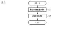
- FIG. 3 is a flowchart showing specific position transmission processing performed by the transmitter of FIG. 2.
- FIG. 2 is a flowchart showing a process performed by the wheel position specifying device of FIG. 1 when determining whether a transmitter is attached to a front wheel or a rear wheel.
- 2 is a flowchart showing a wheel position specifying process performed by the wheel position specifying device of FIG. 1 using ABS.
- 2 is a flowchart showing a process performed by the wheel position specifying device of FIG. 1 when determining whether a transmitter is attached to a front wheel or a rear wheel.
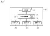
- vehicle 10 includes a plurality of wheel assemblies 11 and 12. As shown in FIG. 1, vehicle 10 includes a plurality of wheel assemblies 11 and 12. As shown in FIG. Each wheel assembly 11, 12 includes a wheel 13 and a tire 14. The plurality of wheel assemblies 11, 12 include a front wheel 11 and a rear wheel 12. Vehicle 10 is a two-wheeled vehicle. The outer diameter of the front wheel 11 and the outer diameter of the rear wheel 12 are different. For example, the outer diameter of the front wheel 11 and the outer diameter of the rear wheel 12 are different because the tire size of the front wheel 11 and the tire size of the rear wheel 12 are different. The outer diameter of the front wheel 11 may be larger than the outer diameter of the rear wheel 12. The outer diameter of the front wheel 11 may be smaller than the outer diameter of the rear wheel 12.
- the outer diameter of the front wheel 11 is larger than the outer diameter of the rear wheel 12.
- the outer diameter of the front wheel 11 is smaller than the outer diameter of the rear wheel 12.
- Vehicle 10 may be equipped with ABS 20.
- ABS20 is an anti-lock braking system.
- ABS 20 includes wheel speed sensors 21 and 22.
- Wheel speed sensors 21 and 22 detect pulses generated when wheel assemblies 11 and 12 rotate. A predetermined number of pulses occur during one revolution of the wheel assemblies 11, 12.
- the wheel speed sensors 21 and 22 include a first wheel speed sensor 21 and a second wheel speed sensor 22.
- the first wheel speed sensor 21 is provided corresponding to the front wheel 11 .
- the first wheel speed sensor 21 detects a pulse generated when the front wheel 11 rotates.
- the second wheel speed sensor 22 is provided corresponding to the rear wheel 12.
- the second wheel speed sensor 22 detects pulses generated when the rear wheel 12 rotates.
- the ABS 20 includes an ABS controller 23.
- the ABS controller 23 is configured by, for example, a microcomputer.
- the ABS controller 23 acquires pulses from the wheel speed sensors 21 and 22.
- the ABS controller 23 counts the falling and rising pulses of each wheel speed sensor 21 and 22. The value obtained thereby is the pulse count number.
- the ABS controller 23 calculates the remainder when the pulse count obtained by counting is divided by the pulse count for one rotation of the wheel assemblies 11 and 12 as a pulse count value. By knowing how many times the wheel assemblies 11, 12 have rotated per pulse count value 1, the rotation angle of the wheel assemblies 11, 12 can be calculated from the pulse count value.
- the pulse count value is information indicating the rotation angle of the wheel assemblies 11 and 12.
- the vehicle 10 is equipped with a wheel position identification system 30.
- the wheel position identification system 30 includes a transmitter 31 .
- the transmitter 31 is attached to each of the front wheel 11 and the rear wheel 12.
- the transmitter 31 may be attached to each wheel assembly 11, 12 by being integrally provided with a tire valve.
- the transmitter 31 may be attached to the tire 14 of each wheel assembly 11, 12.
- the transmitter 31 includes a pressure sensor 32.
- the pressure sensor 32 detects the internal pressure of the corresponding tire 14.
- the transmitter 31 includes a temperature sensor 33.
- Temperature sensor 33 detects the temperature within the corresponding tire 14 .
- the transmitter 31 includes an acceleration sensor 34.
- the acceleration sensor 34 is attached to the wheel assemblies 11, 12 so as to be able to detect the centrifugal force generated by the rotation of the wheel assemblies 11, 12.
- the acceleration sensor 34 includes a detection shaft 35.
- the acceleration sensor 34 detects acceleration in the direction in which the detection shaft 35 extends.
- the acceleration sensor 34 is attached to the wheel assemblies 11, 12 so that the detection axis 35 points vertically upward when the transmitter 31 is located at the top of the wheel assemblies 11, 12.
- the transmitter 31 includes a transmitter control device 36.
- the transmitter control device 36 includes a processor 37 and a transmitter storage section 38.
- Examples of the processor 37 include an MPU (Micro Processing Unit), a CPU (Central Processing Unit), and a DSP (Digital Signal Processor).
- the transmitter storage unit 38 includes a RAM (Random Access Memory) and a ROM (Read Only Memory).
- the transmitter storage unit 38 stores program codes or instructions configured to cause the processor 37 to perform processing.
- the transmitter control device 36 may be configured by a hardware circuit such as an ASIC (Application Specific Integrated Circuit) or an FPGA (Field Programmable Gate Array).
- the transmitter controller 36 which is a processing circuit, may include one or more processors operating according to a computer program, one or more hardware circuits such as ASIC or FPGA, or a combination thereof.
- ROM and RAM or computer readable media include any available media that can be accessed by a general purpose or special purpose computer.
- the transmitter storage unit 38 stores an ID code indicating unique identification information of the corresponding transmitter 31.
- the ID code of the transmitter 31 attached to the front wheel 11 and the ID code of the transmitter 31 attached to the rear wheel 12 are different. Let the ID code of the transmitter 31 attached to the front wheel 11 be the first code. The ID code of the transmitter 31 attached to the rear wheel 12 is defined as a second code.
- the transmitter control device 36 generates transmission data.
- the transmission data is digital data and is binary data.
- the transmitted data includes pressure data, temperature data, and ID code.
- the pressure data is data indicating the pressure detected by the pressure sensor 32.
- the temperature data is data indicating the temperature detected by the temperature sensor 33.
- the transmitter 31 includes a transmitting circuit 39 .
- the transmission circuit 39 performs modulation according to the transmission data input from the transmitter control device 36.
- the transmitter 31 includes a transmitting antenna 40 .
- the transmitter circuit 39 transmits a transmit signal, which is a wireless signal modulated according to the transmit data, from the transmit antenna 40 .
- the transmission circuit 39 transmits a transmission signal including the ID code.
- the transmission signal is a signal in a predetermined frequency band. Examples of frequency bands include LF band, MF band, HF band, VHF band, UHF band, and 2.4 GHz band.
- the transmission signal transmitted from the transmitter 31 mounted on the front wheel 11 is referred to as a first transmission signal.
- the transmission signal transmitted from the transmitter 31 mounted on the rear wheel 12 is referred to as a second transmission signal.
- the transmitter control device 36 performs specific position transmission processing.
- the specific position transmission process is performed, for example, when the vehicle 10 starts traveling after the vehicle 10 has been stopped for a predetermined period of time or more.
- the predetermined time is, for example, several tens of minutes to several hours.
- Whether or not the vehicle 10 is traveling can be determined from the acceleration detected by the acceleration sensor 34. As the vehicle speed increases, the centrifugal acceleration acting on the acceleration sensor 34 increases. If the acceleration detected by the acceleration sensor 34 is greater than or equal to the running determination threshold, the transmitter control device 36 determines that the vehicle 10 is running. If the acceleration detected by the acceleration sensor 34 is less than the running determination threshold, the transmitter control device 36 determines that the vehicle 10 is stopped.
- the running determination threshold value is set to a value larger than the acceleration detected by the acceleration sensor 34 when the vehicle 10 is stopped, taking into account tolerances and the like. The processing performed by the transmitter control device 36 when performing the specific position transmission processing will be described below.
- step S1 the transmitter control device 36 detects that the transmitter 31 is located at a specific rotational position of the wheel assemblies 11, 12.
- the fact that the transmitter 31 is located at a particular rotational position can be detected by the acceleration detected by the acceleration sensor 34.
- Centrifugal acceleration and gravitational acceleration act on the detection shaft 35.
- gravitational acceleration always acts in a vertically downward direction.
- the direction of the detection shaft 35 changes as the wheel assemblies 11 and 12 rotate. Therefore, the gravitational acceleration component detected by the acceleration sensor 34 changes as the wheel assemblies 11 and 12 rotate.
- the centrifugal acceleration changes only slightly during one revolution of the wheel assemblies 11, 12. Therefore, the change in acceleration detected by the acceleration sensor 34 during one rotation of the wheel assemblies 11, 12 can be considered as a change in the gravitational acceleration component due to the change in the direction of the detection shaft 35.
- the gravitational acceleration component detected by the acceleration sensor 34 changes between +1 [G] and -1 [G] while the wheel assemblies 11 and 12 make one rotation.
- the gravitational acceleration component detected when the detection axis 35 points vertically downward is +1 [G].
- the acceleration sensor 34 when the position of the acceleration sensor 34 changes from a position where the detection axis 35 faces vertically downward to a position where the detection axis 35 faces vertically upward, the acceleration sensor 34 The acceleration detected by this decreases. On the other hand, if the position of the acceleration sensor 34 changes from a position where the detection axis 35 faces vertically upward to a position where the detection axis 35 faces vertically downward, the acceleration sensor 34 detects The applied acceleration increases.
- the transmitter control device 36 acquires the detection results of the acceleration sensor 34 at predetermined intervals. The transmitter control device 36 compares the detection result of the acceleration sensor 34 with the previous value every time it obtains the detection result.
- a case where the detection result of the acceleration sensor 34 has increased from the previous value is considered as an increase, and a case where the detection result of the acceleration sensor 34 has decreased from the previous value is considered a decrease.
- the transmitter controller 36 determines that the transmitter 31 is located at a particular rotational position of the wheel assemblies 11, 12 when the pattern of decreases and increases is a predetermined pattern. For example, the transmitter control device 36 determines that the transmitter 31 is located at a specific rotational position when the detection result of the acceleration sensor 34 changes from decreasing to increasing. Thereby, the transmitter control device 36 detects that the transmitter 31 is located at a specific rotational position of the wheel assemblies 11, 12.
- the transmitter control device 36 transmits a transmission signal from the transmission circuit 39.
- the transmitter control device 36 can send a signal from the transmitter circuit 39 when it detects that the transmitter 31 is located at a specific rotational position of the wheel assemblies 11, 12. It is possible to send a signal.
- the specific rotational position in this embodiment is a position where the detection axis 35 faces vertically upward.
- the specific rotational position is a predetermined range that allows for error. Due to various factors, errors occur in the position of the transmitter 31 when the transmitter control device 36 detects a specific rotational position. The various factors include the frequency with which the transmitter control device 36 acquires the detection results of the acceleration sensor 34 and the detection error of the acceleration sensor 34 .
- the "specific rotational position" allows for these errors.
- the specific rotational position can also be said to be a specific range that includes a tolerance range that allows for errors.
- the wheel position identification system 30 includes a wheel position identification device 50.
- the wheel position specifying device 50 is mounted on the vehicle 10.
- the wheel position specifying device 50 is provided, for example, on the vehicle body.
- the wheel position specifying device 50 includes a specifying device control device 51.
- the specific device control device 51 includes a processor 52 and a specific device storage unit 53. Examples of the processor 52 include an MPU, a CPU, and a DSP.
- the specific device storage unit 53 includes a ROM, a RAM, and a rewritable nonvolatile storage medium.
- the specific device storage unit 53 stores program codes or instructions configured to cause the processor 52 to execute processes.
- the specific device control device 51 may be configured by a hardware circuit such as ASIC or FPGA.
- the specific device control device 51 which is a processing circuit, may include one or more processors that operate according to a computer program, one or more hardware circuits such as ASIC or FPGA, or a combination thereof.
- ROM and RAM or computer readable media include any available media that can be accessed by a general purpose or special purpose computer.
- the specific device control device 51 is configured to be able to acquire a pulse count value from the ABS controller 23.
- the wheel position identifying device 50 includes a receiving antenna 54 .
- the receiving antenna 54 receives the transmission signal transmitted from each transmitter 31.
- the wheel position specifying device 50 includes a receiving circuit 55.
- the reception circuit 55 obtains transmission data by demodulating the transmission signal received via the reception antenna 54.
- the receiving circuit 55 outputs transmission data to the specific device control device 51.
- the specific device control device 51 acquires the pressure data, temperature data, and ID code.
- the specific device control device 51 can determine whether or not an abnormality has occurred in the tire 14.
- the specific device control device 51 can determine whether an abnormality has occurred in the internal pressure of the tire 14 from the pressure data.
- the specific device control device 51 can determine whether or not there is an abnormality in the temperature inside the tire 14 from the temperature data.
- the specific device control device 51 may provide notification via the display unit when an abnormality has occurred in the tire 14.
- the display section is arranged, for example, at a position that is visible to a passenger of the vehicle 10.
- the specifying device control device 51 performs wheel position specifying processing.
- the wheel position specifying process is to associate each wheel assembly 11, 12 with the ID code of each transmitter 31.
- the correspondence between each wheel assembly 11, 12 and the ID code of each transmitter 31 can also be said to specify whether each of the two transmitters 31 is attached to the front wheel 11 or the rear wheel 12. .
- the specific device control device 51 associates the pressure of the tire 14 with the position of the wheel assembly 11, 12 and displays it on the display section. can be displayed. Further, when an abnormality occurs in the tire 14, the specific device control device 51 can display the position of the tire 14 where the abnormality has occurred on the display section.
- the wheel position specifying process is performed, for example, when the vehicle 10 is changed from a stopped state to a started state by operating a start switch.
- the start switch is also called the ignition switch.
- the transmission signal is transmitted by specific position transmission processing.
- the wheel position specifying process is performed by the specifying device control device 51, so that it is specified whether each of the transmitters 31 is attached to the front wheel 11 or the rear wheel 12 by the wheel position specifying method.
- the specific device control device 51 determines the rotation period [msec] of the front wheel 11.
- the specific device control device 51 may calculate the rotation period of the front wheel 11 from the outer diameter of the front wheel 11 and the speed of the vehicle 10.
- the outer diameter of the front wheel 11 is stored in the specific device storage unit 53, for example.
- the speed of the vehicle 10 can be obtained from the ABS controller 23, for example.
- the specific device control device 51 may determine the rotation period of the front wheels 11 using data that associates the rotation period of the front wheels 11 with the speed of the vehicle 10. If the outer diameter of the front wheel 11 is known in advance, the rotation period of the front wheel 11 corresponding to the speed of the front wheel 11 can be calculated in advance. By storing the calculated data in the specific device storage unit 53, the specific device control device 51 can determine the rotation period of the front wheels 11 from the speed of the vehicle 10.
- step S12 the specific device control device 51 determines the rotation period [msec] of the rear wheel 12.
- the rotation period of the rear wheel 12 can be determined using the same method as the rotation period of the front wheel 11.
- the specific device control device 51 may calculate the rotation period of the rear wheel 12 from the outer diameter of the rear wheel 12 and the speed of the vehicle 10, or may calculate the rotation period of the rear wheel 12 from the speed of the vehicle 10.
- the rotation period of the rear wheel 12 may be determined using .
- step S13 the specific device control device 51 acquires the transmission data demodulated by the reception circuit 55 receiving the transmission signal.
- step S14 the specific device control device 51 calculates the reception interval [msec] of the transmission signal for each ID code.
- the specific device control device 51 acquires the ID code from the transmission data, it calculates the elapsed time since the last acquisition of transmission data containing the same ID code as the ID code. Thereby, the reception interval of the transmission signal can be calculated for each ID code.
- the specific device control device 51 acquires the transmission data including the first code, it calculates the elapsed time since the last acquisition of the transmission data including the first code, thereby determining the reception of the first transmission signal. Calculate the interval.
- the specific device control device 51 acquires the transmission data including the second code, it calculates the elapsed time since the last acquisition of the transmission data including the second code, thereby determining the reception of the second transmission signal. Calculate the interval.
- the specific device control device 51 determines the transmitter 31 attached to the front wheel 11. If the difference between the reception interval of the first transmission signal and the rotation period of the front wheel 11 is smaller than the difference between the reception interval of the second transmission signal and the rotation period of the front wheel 11, the specific device control device 51 transmits the first transmission signal. It is determined that the transmitter 31 that transmitted the signal is attached to the front wheel 11. That is, the specific device control device 51 selects the transmitter mounted on the front wheel 11 to transmit the transmission signal with the smaller difference between the reception interval and the rotation period of the front wheel 11 out of two types of transmission signals with different reception intervals. It is determined that the signal is the first transmission signal transmitted from No. 31. Thereby, the specific device control device 51 can specify the transmitter 31 attached to the front wheel 11, and can associate the first code with the front wheel 11.
- the specific device control device 51 determines the transmitter 31 attached to the rear wheel 12. If the difference between the reception interval of the second transmission signal and the rotation period of the rear wheel 12 is smaller than the difference between the reception interval of the first transmission signal and the rotation period of the rear wheel 12, the specific device control device 51 It is determined that the transmitter 31 that transmitted the 2 transmission signal is attached to the rear wheel 12. That is, the specific device control device 51 selects the transmission signal that has a smaller difference between the reception interval and the rotation period of the rear wheel 12 from among the two types of transmission signals with different reception intervals, which is attached to the rear wheel 12. It is determined that it is the second transmission signal transmitted from the transmitter 31. Thereby, the specific device control device 51 can specify the transmitter 31 attached to the rear wheel 12 and can associate the second code with the rear wheel 12.
- step S17 the specific device control device 51 stores the correspondence between the ID code and the wheel assemblies 11 and 12 in the specific device storage section 53. After completing the process in step S17, the specific device control device 51 ends the wheel position specifying process.
- the transmitter 31 transmits a transmission signal at a specific rotational position of the wheel assemblies 11 and 12.
- the time from when the transmitter 31 is positioned at a specific rotational position of the wheel assemblies 11, 12 to when the transmitter 31 is positioned at the next specific rotational position of the wheel assemblies 11, 12 corresponds to the rotation period of If the transmitter 31 is attached to the front wheel 11, the state in which the transmitter 31 is located at a specific rotational position of the front wheel 11 until the transmitter 31 is located at the next specific rotational position of the front wheel 11 is The time corresponds to the rotation period of the front wheel 11. Therefore, the transmission interval of the first transmission signal depends on the rotation period of the front wheel 11. Similarly, the transmission interval of the second transmission signal depends on the rotation period of the rear wheel 12.
- the specific device control device 51 determines whether each of the transmitters 31 is attached to the front wheel 11 or not from the reception interval of the first transmission signal and the reception interval of the second transmission signal. It can be determined whether the device is attached to the device.
- the specific device control device 51 determines that among the two types of transmission signals with different reception intervals, the transmission signal with the smaller difference between the reception interval and the rotation period of the front wheel 11 is the first transmission signal. judge.
- the transmission interval of the transmission signal from the transmitter 31 attached to the front wheel 11 depends on the rotation period of the front wheel 11. Therefore, the difference between the reception interval of the transmission signal from the transmitter 31 mounted on the front wheel 11 and the rotation period of the front wheel 11 is the difference between the reception interval of the transmission signal from the transmitter 31 mounted on the rear wheel 12 and the rotation period of the front wheel 11. is smaller than the difference between the rotation period of Thereby, the specific device control device 51 can determine that the transmission signal with the smaller difference between the reception interval and the rotation period of the front wheel 11 is the first transmission signal among the two types of transmission signals with different reception intervals. .
- a second embodiment of a wheel position specifying device, a wheel position specifying system, and a wheel position specifying method will be described.
- the processing performed by the specific device control device is different from the first embodiment.
- the wheel position specifying process of the first embodiment and the wheel position specifying process using ABS are used together.
- step S21 the specific device control device 51 converts the pulse count values of each wheel speed sensor 21, 22 into the ABS every time transmission data is acquired, in other words, every time a transmission signal is received. Obtained from the controller 23.
- the specific device control device 51 performs position determination.
- the position determination is to determine whether each transmitter 31 is attached to the front wheel 11 or the rear wheel 12. Position determination is performed by acquiring a pulse count value each time transmission data is acquired. If the transmitter 31 is transmitting a transmission signal at a particular rotational position, the rotation angle of each of the two wheel assemblies 11, 12 is the rotation at which the transmission signal is transmitted from either of the two transmitters 31. synchronized with the angle. Therefore, when each transmitter 31 transmits a transmission signal at a specific rotational position, when a pulse count value is obtained upon reception of the transmission signal, a wheel with a small variation in pulse count value corresponds to each transmitter 31. Speed sensors 21, 22 are present.
- the specific device control device 51 determines which of the wheel assemblies 11 and 12 each transmitter 31 is attached to from the variation in pulse count values collected each time transmission data is acquired. That is, the specific device control device 51 allows each transmitter 31 to control the wheel assembly 11 based on the variation in the rotation angle of the front wheel 11 when receiving the transmission signal and the variation in the rotation angle of the rear wheel 12 when receiving the transmission signal. , 12 to which it is attached.
- the specific device control device 51 collects pulse count values for each wheel speed sensor 21 and 22 every time the receiving circuit 55 receives a transmission signal. When the collected pulse count value falls within a predetermined range, the specific device control device 51 associates the transmitter 31 with the wheel assemblies 11 and 12 corresponding to the wheel speed sensors 21 and 22 that detected the pulse count value.
- the predetermined range is a range that is set in consideration of variations in pulse count values, and is used to determine which wheel speed sensors 21 and 22 have less variation in pulse count values. Thereby, the specific device control device 51 can use the ABS 20 to determine whether each of the transmitters 31 is attached to the front wheel 11 or the rear wheel 12.
- the specific device control device 51 acquires the pulse count values of the wheel speed sensors 21 and 22 every time the specific device control device 51 acquires transmission data including the first code.
- the variation in the pulse count value of the first wheel speed sensor 21 is smaller than the variation in the pulse count value of the second wheel speed sensor 22. Therefore, it can be determined that the transmitter 31 of the first code is attached to the front wheel 11.
- the specific device control device 51 repeatedly performs the processes of step S21 and step S22 until the ID code of each transmitter 31 and the wheel assemblies 11, 12 are associated with each other.
- the specific device control device 51 determines whether each of the transmitters 31 is attached to the front wheel 11 or not by performing the processing in steps S11 to S17, as in the first embodiment. It is determined whether it is attached to the wheel 12. Through the processing in steps S11 to S17, a determination result of the wheel position specifying process based on the reception interval of the first transmission signal and the reception interval of the second transmission signal is obtained.
- the wheel position identification process based on the reception interval of the first transmission signal and the reception interval of the second transmission signal is referred to as the first wheel position identification process.
- the specific device control device 51 After completing the processing in steps S11 to S17, the specific device control device 51 performs the processing in step S18. If the specific device control device 51 cannot determine whether each of the transmitters 31 is attached to the front wheel 11 or the rear wheel 12 through the processing in steps S11 to S17, the specific device control device 51 executes the processing in step S18. You may do so.
- step S18 the specific device control device 51 determines whether the wheel position specifying process using the ABS 20 is completed. If the determination result in step S18 is negative, the specific device control device 51 performs the determination in step S18 again. If the determination result in step S18 is affirmative, the specific device control device 51 performs the process in step S19. It can be said that the specific device control device 51 repeats the determination in step S18 until the determination result in step S18 becomes affirmative.
- the wheel position specifying process using the ABS 20 is referred to as the second wheel position specifying process.
- step S19 the specific device control device 51 updates the correspondence between the ID code and the wheel assemblies 11 and 12.
- the identification device control device 51 determines whether each of the transmitters 31 is attached to the front wheel 11 or the rear wheel 12 based on the determination result of the first wheel position determination process and the determination result of the second wheel position determination process. Determine whether it is installed.
- the specifying device control device 51 gives priority to the determination result of the second wheel position specifying process. That is, the identification device control device 51 updates the correspondence between the ID code and the wheel assemblies 11 and 12 with the determination result of the second wheel position identification process, regardless of the determination result of the first wheel position identification process.
- the identification device control device 51 identifies the ID code and the wheel assembly 11, 12 based on the matched determination result. The correspondence relationship may be updated. If the determination result of the first wheel position specifying process and the determination result of the second wheel position specifying process do not match, the specifying device control device 51 executes the first wheel position specifying process and the second wheel position specifying process. You may try again.
- the identification device control device 51 determines whether each of the transmitters 31 is attached to the front wheel 11 based on the determination result of the first wheel position identification process and the determination result of the second wheel position identification process. It is determined whether the vehicle is attached to the rear wheel 12 or not.
- the second wheel position specifying process has higher accuracy in determining which wheel assembly 11, 12 the transmitter 31 is attached to than the first wheel position specifying process.
- the first wheel position specifying process takes less time than the second wheel position specifying process to determine which wheel assembly 11 or 12 the transmitter 31 is attached to.
- the determination result of the first wheel position specifying process is used until the second wheel position specifying process is completed, and the determination result of the second wheel position specifying process is used after the second wheel position specifying process is completed. I am using it. This reduces the time required to determine which wheel assembly 11, 12 the transmitter 31 is attached to, and the accuracy of determining which wheel assembly 11, 12 the transmitter 31 is attached to. It is possible to achieve both improvements in
- the outer diameter of the front wheel 11 and the outer diameter of the rear wheel 12 may become the same. In this case, it cannot be determined by the first wheel position specifying process whether each of the transmitters 31 is attached to the front wheel 11 or the rear wheel 12.
- the first wheel position specifying process and the second wheel position specifying process it is not possible to determine whether each of the transmitters 31 is attached to the front wheel 11 or the rear wheel 12 by the first wheel position specifying process. Even in this case, it is possible to determine whether each transmitter 31 is attached to the front wheel 11 or the rear wheel 12 by the second wheel position specifying process.
- the ABS 20 may include wheel speed sensors 21 and 22 corresponding to one of the front wheels 11 and the rear wheels 12.
- the ABS 20 may include a first wheel speed sensor 21 corresponding to the front wheel 11 and may not include a second wheel speed sensor 22 corresponding to the rear wheel 12.
- the specific device control device 51 may only determine which of the two transmitters 31 is attached to the front wheel 11 by the second wheel position specifying process. can. When the specific device control device 51 determines which of the two transmitters 31 is attached to the front wheel 11, it may determine that the remaining transmitters 31 are attached to the rear wheel 12.
- the specific device control device 51 may determine that the remaining one transmitter 31 is attached to the rear wheel 12. Similarly, the specific device control device 51 determines which transmitter 31 is attached to the rear wheel 12 based on the rotation period of the rear wheel 12, and determines that the remaining transmitters 31 are attached to the front wheel 11. Good too.
- the specific device control device 51 determines whether each of the transmitters 31 is attached to the front wheel 11 by comparing the reception interval of the first transmission signal and the reception interval of the second transmission signal. 12 may be determined. When the outer diameter of the front wheel 11 is larger than the outer diameter of the rear wheel 12, the reception interval of the first transmission signal is longer than the reception interval of the second transmission signal. In this case, the specific device control device 51 can determine that the transmitter 31 that has transmitted the transmission signal with a long reception interval is attached to the front wheel 11. The specific device control device 51 can determine that the transmitter 31 that has transmitted the transmission signal with a short reception interval is attached to the rear wheel 12.
- the specific device control device 51 can determine that the transmitter 31 that has transmitted the transmission signal with a short reception interval is attached to the front wheel 11.
- the specific device control device 51 can determine that the transmitter 31 that has transmitted the transmission signal with a long reception interval is attached to the rear wheel 12. Whether the outer diameter of the front wheel 11 is larger or smaller than the outer diameter of the rear wheel 12 may be stored in the specific device storage section 53.
- the vehicle 10 may be a four-wheeled vehicle as long as the outer diameter of the front wheels 11 and the outer diameter of the rear wheels 12 are different.
- "two types of transmission signals with different reception intervals" means two types of transmission signals whose reception intervals are substantially different due to a difference in the outer diameter of the wheel assembly. Although there may be slight differences in the reception intervals of the respective transmission signals transmitted from two wheel assemblies of substantially equal outer diameter, such differences are within the tolerance range and the actual reception interval It is not included in the difference.
- the specifying device control device 51 may give priority to the determination result of the first wheel position specifying process.
- the identification device control device 51 may use the determination result of the second wheel position identification process when the determination cannot be made by the first wheel position identification process.
Abstract
L'invention concerne un véhicule (10) pourvu d'une roue avant (11) et d'une roue arrière (12) ayant des diamètres externes mutuellement différents. Un dispositif d'identification de position de roue (50) comprend : un circuit de réception (55) configuré pour recevoir un premier signal d'émission qui est émis à partir d'un émetteur (31) monté sur la roue avant (11) et qui est émis à une position de rotation spécifique de la roue avant (11) et un second signal d'émission qui est émis à partir d'un émetteur (31) monté sur la roue arrière (12) et qui est émis à une position de rotation spécifique de la roue arrière (12) ; et un dispositif de commande de dispositif spécifique (51). Le dispositif de commande de dispositif spécifique (51) est configuré pour déterminer, à partir d'un intervalle de réception du premier signal d'émission et d'un intervalle de réception du second signal d'émission, si chaque émetteur (31) est monté sur la roue avant (11) ou est monté sur la roue arrière (12).
Priority Applications (2)
| Application Number | Priority Date | Filing Date | Title |
|---|---|---|---|
| PCT/JP2022/032361 WO2024047690A1 (fr) | 2022-08-29 | 2022-08-29 | Dispositif d'identification de position de roue, système d'identification de position de roue et procédé d'identification de position de roue |
| CN202280060467.8A CN117980158A (zh) | 2022-08-29 | 2022-08-29 | 轮位置确定装置、轮位置确定系统以及轮位置确定方法 |
Applications Claiming Priority (1)
| Application Number | Priority Date | Filing Date | Title |
|---|---|---|---|
| PCT/JP2022/032361 WO2024047690A1 (fr) | 2022-08-29 | 2022-08-29 | Dispositif d'identification de position de roue, système d'identification de position de roue et procédé d'identification de position de roue |
Publications (1)
| Publication Number | Publication Date |
|---|---|
| WO2024047690A1 true WO2024047690A1 (fr) | 2024-03-07 |
Family
ID=90099067
Family Applications (1)
| Application Number | Title | Priority Date | Filing Date |
|---|---|---|---|
| PCT/JP2022/032361 WO2024047690A1 (fr) | 2022-08-29 | 2022-08-29 | Dispositif d'identification de position de roue, système d'identification de position de roue et procédé d'identification de position de roue |
Country Status (2)
| Country | Link |
|---|---|
| CN (1) | CN117980158A (fr) |
| WO (1) | WO2024047690A1 (fr) |
Citations (8)
| Publication number | Priority date | Publication date | Assignee | Title |
|---|---|---|---|---|
| JP2004026062A (ja) * | 2002-06-27 | 2004-01-29 | Denso Corp | タイヤ空気圧センサの位置識別方法、タイヤ空気圧センサのid登録方法、タイヤ空気圧センサの位置識別システム、タイヤ空気圧センサのid登録システム及びタイヤ空気圧監視システム |
| JP2006111205A (ja) * | 2004-10-18 | 2006-04-27 | Denso Corp | タイヤ空気圧検出装置 |
| US20090076663A1 (en) * | 2007-09-18 | 2009-03-19 | Continental Automotive Gmbh | Method and Device for Assigning a Wheel of a Motor Vehicle |
| EP2586633A1 (fr) * | 2011-10-31 | 2013-05-01 | Samsung Electro-Mechanics Co., Ltd | Dispositif et procédé pour détecter une position de pneu |
| JP2013133057A (ja) * | 2011-12-27 | 2013-07-08 | Denso Corp | 車輪位置検出装置およびそれを備えたタイヤ空気圧検出装置 |
| WO2018131664A1 (fr) * | 2017-01-11 | 2018-07-19 | 株式会社デンソー | Émetteur de capteur, dispositif de détection de position de roue et dispositif de détection de pression d'air de pneu équipés de celui-ci |
| JP2019055755A (ja) * | 2017-09-22 | 2019-04-11 | 株式会社東海理化電機製作所 | タイヤ位置登録システム |
| JP2022056921A (ja) | 2020-09-30 | 2022-04-11 | 株式会社ブリヂストン | タイヤ状態監視システム、バッテリの放電容量推測プログラムおよび放電容量推測方法 |
-
2022
- 2022-08-29 CN CN202280060467.8A patent/CN117980158A/zh active Pending
- 2022-08-29 WO PCT/JP2022/032361 patent/WO2024047690A1/fr active Application Filing
Patent Citations (8)
| Publication number | Priority date | Publication date | Assignee | Title |
|---|---|---|---|---|
| JP2004026062A (ja) * | 2002-06-27 | 2004-01-29 | Denso Corp | タイヤ空気圧センサの位置識別方法、タイヤ空気圧センサのid登録方法、タイヤ空気圧センサの位置識別システム、タイヤ空気圧センサのid登録システム及びタイヤ空気圧監視システム |
| JP2006111205A (ja) * | 2004-10-18 | 2006-04-27 | Denso Corp | タイヤ空気圧検出装置 |
| US20090076663A1 (en) * | 2007-09-18 | 2009-03-19 | Continental Automotive Gmbh | Method and Device for Assigning a Wheel of a Motor Vehicle |
| EP2586633A1 (fr) * | 2011-10-31 | 2013-05-01 | Samsung Electro-Mechanics Co., Ltd | Dispositif et procédé pour détecter une position de pneu |
| JP2013133057A (ja) * | 2011-12-27 | 2013-07-08 | Denso Corp | 車輪位置検出装置およびそれを備えたタイヤ空気圧検出装置 |
| WO2018131664A1 (fr) * | 2017-01-11 | 2018-07-19 | 株式会社デンソー | Émetteur de capteur, dispositif de détection de position de roue et dispositif de détection de pression d'air de pneu équipés de celui-ci |
| JP2019055755A (ja) * | 2017-09-22 | 2019-04-11 | 株式会社東海理化電機製作所 | タイヤ位置登録システム |
| JP2022056921A (ja) | 2020-09-30 | 2022-04-11 | 株式会社ブリヂストン | タイヤ状態監視システム、バッテリの放電容量推測プログラムおよび放電容量推測方法 |
Also Published As
| Publication number | Publication date |
|---|---|
| CN117980158A (zh) | 2024-05-03 |
Similar Documents
| Publication | Publication Date | Title |
|---|---|---|
| JP6412605B2 (ja) | 車輪の速度センサ及び加速度センサを用いて、タイヤの状態及び位置を計測する方法及び装置 | |
| US10112448B2 (en) | Tire wheel position detection device and tire pressure monitoring system having the same | |
| US8498759B1 (en) | Method and apparatus for determining a condition and relative location of an inner tire and an outer tire of a tire pair | |
| US10882366B2 (en) | Electronic wheel unit for a vehicle wheel, and method for operating an electronic wheel unit of this kind | |
| US20140379291A1 (en) | Wheel position detector and tire inflation pressure detector having the same | |
| CN108237848B (zh) | 轮胎位置定位方法和装置 | |
| US9694631B2 (en) | Tire position determination system | |
| WO2018113471A1 (fr) | Procédé et appareil pour localiser une position de pneu | |
| WO2013108538A1 (fr) | Détecteur de position de roue et détecteur de pression de gonflage de pneu présentant celui-ci | |
| EP3202600B1 (fr) | Système de surveillance de pression de pneu | |
| US10710418B2 (en) | Method for wireless optimization of wheel monitoring in a vehicle, a wheel monitoring system of a vehicle, and electronic wheel unit and control device for a wheel monitoring system | |
| EP3690448B1 (fr) | Dispositif de détection d'accélération | |
| EP3118029B1 (fr) | Système d'enregistrement de position des pneus | |
| US20050150284A1 (en) | System for controlling a vehicle wheel tyre pressure | |
| WO2024047690A1 (fr) | Dispositif d'identification de position de roue, système d'identification de position de roue et procédé d'identification de position de roue | |
| EP3656586B1 (fr) | Système de surveillance d'état de pneu, émetteur et récepteur | |
| EP3769977B1 (fr) | Système de surveillance d'état de pneu, émetteur et récepteur | |
| JP6375970B2 (ja) | 車輪位置検出装置およびそれを備えたタイヤ空気圧検出システム | |
| WO2016121363A1 (fr) | Dispositif de détection de position de roue et système de surveillance de la pression des pneus | |
| JP6756822B2 (ja) | 受信機、及び、送信機ユニット | |
| WO2016121365A1 (fr) | Dispositif de détection de position de roue et système de détection de pression de pneu doté de celui-ci | |
| JP7419551B2 (ja) | 輪位置特定システム、及び輪位置特定装置 | |
| JP5626126B2 (ja) | 車輪位置検出装置およびそれを備えたタイヤ空気圧検出装置 | |
| JP6985560B1 (ja) | 送信機 | |
| WO2023026455A1 (fr) | Système d'identification de position de roue, dispositif d'identification de position de roue et procédé d'identification de position de roue |
Legal Events
| Date | Code | Title | Description |
|---|---|---|---|
| WWE | Wipo information: entry into national phase |
Ref document number: 2022956684 Country of ref document: EP |
|
| ENP | Entry into the national phase |
Ref document number: 2022956684 Country of ref document: EP Effective date: 20240319 |
|
| 121 | Ep: the epo has been informed by wipo that ep was designated in this application |
Ref document number: 22956684 Country of ref document: EP Kind code of ref document: A1 |