WO2024047690A1 - Wheel position identifying device, wheel position identifying system, and wheel position identifying method - Google Patents
Wheel position identifying device, wheel position identifying system, and wheel position identifying method Download PDFInfo
- Publication number
- WO2024047690A1 WO2024047690A1 PCT/JP2022/032361 JP2022032361W WO2024047690A1 WO 2024047690 A1 WO2024047690 A1 WO 2024047690A1 JP 2022032361 W JP2022032361 W JP 2022032361W WO 2024047690 A1 WO2024047690 A1 WO 2024047690A1
- Authority
- WO
- WIPO (PCT)
- Prior art keywords
- wheel
- transmission signal
- transmitter
- front wheel
- control device
- Prior art date
Links
- 238000000034 method Methods 0.000 title claims description 66
- 230000005540 biological transmission Effects 0.000 claims abstract description 168
- 230000001133 acceleration Effects 0.000 description 50
- 230000000712 assembly Effects 0.000 description 37
- 238000000429 assembly Methods 0.000 description 37
- 238000001514 detection method Methods 0.000 description 22
- 230000005856 abnormality Effects 0.000 description 6
- 230000007423 decrease Effects 0.000 description 3
- 230000003247 decreasing effect Effects 0.000 description 3
- 238000004590 computer program Methods 0.000 description 2
- 238000010586 diagram Methods 0.000 description 2
- 230000000694 effects Effects 0.000 description 2
- 238000012544 monitoring process Methods 0.000 description 2
- 241000270281 Coluber constrictor Species 0.000 description 1
- 241001544487 Macromiidae Species 0.000 description 1
- OQZCSNDVOWYALR-UHFFFAOYSA-N flurochloridone Chemical compound FC(F)(F)C1=CC=CC(N2C(C(Cl)C(CCl)C2)=O)=C1 OQZCSNDVOWYALR-UHFFFAOYSA-N 0.000 description 1
- 230000004048 modification Effects 0.000 description 1
- 238000012986 modification Methods 0.000 description 1
- 230000000630 rising effect Effects 0.000 description 1
- 230000001360 synchronised effect Effects 0.000 description 1
Images


Classifications
-
- B—PERFORMING OPERATIONS; TRANSPORTING
- B60—VEHICLES IN GENERAL
- B60C—VEHICLE TYRES; TYRE INFLATION; TYRE CHANGING; CONNECTING VALVES TO INFLATABLE ELASTIC BODIES IN GENERAL; DEVICES OR ARRANGEMENTS RELATED TO TYRES
- B60C23/00—Devices for measuring, signalling, controlling, or distributing tyre pressure or temperature, specially adapted for mounting on vehicles; Arrangement of tyre inflating devices on vehicles, e.g. of pumps or of tanks; Tyre cooling arrangements
- B60C23/02—Signalling devices actuated by tyre pressure
- B60C23/04—Signalling devices actuated by tyre pressure mounted on the wheel or tyre
Definitions
- the present disclosure relates to a wheel position identification device, a wheel position identification system, and a wheel position identification method.
- the tire condition monitoring system disclosed in Patent Document 1 includes a transmitter and a receiver.
- a tire condition monitoring system is mounted on a vehicle.
- the vehicle includes multiple wheel assemblies.
- the wheel assembly includes a wheel and a tire.
- a transmitter is provided in each of the plurality of wheel assemblies. The transmitter detects the condition of the tires.
- the condition of the tire is, for example, the internal pressure of the tire.
- a transmitter transmits a transmission signal to a receiver.
- the receiver recognizes the condition of the tire by receiving the transmitted signal.
- the receiver receives transmission signals from transmitters provided in each of the plurality of wheel assemblies. It may be desirable for the receiver to determine from which transmitter of a plurality of wheel assemblies a received transmission signal was transmitted.
- a wheel position specifying device mounted on a vehicle including front wheels and rear wheels is provided.
- the outer diameter of the front wheel and the outer diameter of the rear wheel are different.
- the wheel position specifying device includes a first transmission signal transmitted from a transmitter attached to the front wheel at a specific rotational position of the front wheel, and a first transmission signal transmitted from a transmitter attached to the front wheel, and a first transmission signal transmitted from a transmitter attached to the front wheel.
- a receiving circuit configured to receive a second transmission signal transmitted from a mounted transmitter and transmitted at a specific rotational position of the rear wheel;
- a control device The specific device control device determines whether each of the transmitters is attached to the front wheel or the rear wheel from the reception interval of the first transmission signal and the reception interval of the second transmission signal. configured to do so.
- the transmission interval of the first transmission signal depends on the rotation period of the front wheel.
- the transmission interval of the second transmission signal depends on the rotation period of the rear wheel.
- the specific device control device uses the difference in the reception interval of transmission signals due to the difference between the outer diameter of the front wheel and the outer diameter of the rear wheel to determine whether each transmitter is attached to the front wheel or the rear wheel. It is possible to determine whether the
- the identification device control device determines the rotation period of the front wheel from the outer diameter of the front wheel and the speed of the vehicle, and determines the rotation period of the front wheel from the outer diameter of the front wheel and the speed of the vehicle, and selects the reception interval and the
- the transmission signal may be configured to determine that the transmission signal having a smaller difference from the rotation period is the first transmission signal transmitted from a transmitter attached to the front wheel.
- the specifying device control device transmits information indicating the rotation angle of the front wheel and information indicating the rotation angle of the rear wheel each time it receives each of the first transmission signal and the second transmission signal. determine whether each of the transmitters is attached to the front wheel or the rear wheel from the variation in the rotation angle of the front wheels and the variation in the rotation angle of the rear wheels; The transmitter transmits the transmitter based on the determination result based on the reception interval of the first transmission signal and the reception interval of the second transmission signal, and the determination result based on the variation in the rotation angle of the front wheels and the variation in the rotation angle of the rear wheels. It may be configured to specify whether each of the above is attached to the front wheel or the rear wheel.
- a wheel position identification system mounted on a vehicle including front wheels and rear wheels is provided.
- the outer diameter of the front wheel and the outer diameter of the rear wheel are different.
- the wheel position specifying system includes a transmitter attached to each of the front wheel and the rear wheel, and a wheel position specifying device.
- the wheel position specifying device includes a first transmission signal transmitted from a transmitter attached to the front wheel at a specific rotational position of the front wheel, and a first transmission signal transmitted from a transmitter attached to the front wheel, and a first transmission signal transmitted from a transmitter attached to the front wheel.
- a receiving circuit configured to receive a second transmission signal transmitted from a mounted transmitter and transmitted at a specific rotational position of the rear wheel;
- a control device The specific device control device determines whether each of the transmitters is attached to the front wheel or the rear wheel from the reception interval of the first transmission signal and the reception interval of the second transmission signal. configured to do so.
- the transmission interval of the first transmission signal depends on the rotation period of the front wheel.
- the transmission interval of the second transmission signal depends on the rotation period of the rear wheel.
- the specific device control device uses the difference in the reception interval of transmission signals due to the difference between the outer diameter of the front wheel and the outer diameter of the rear wheel to determine whether each transmitter is attached to the front wheel or the rear wheel. It is possible to determine whether the
- a wheel positioning method for a vehicle including front wheels and rear wheels is provided.
- the outer diameter of the front wheel and the outer diameter of the rear wheel are different.
- the wheel position specifying method includes the steps of: receiving a first transmission signal transmitted from a transmitter attached to the front wheel, the first transmission signal being transmitted at a specific rotational position of the front wheel; receiving a second transmission signal transmitted from a transmitter mounted on the rear wheel at a specific rotational position of the rear wheel; and determining the reception interval of the first transmission signal; determining whether each of the transmitters is attached to the front wheel or the rear wheel from the reception interval of the second transmission signal.
- the transmission interval of the first transmission signal depends on the rotation period of the front wheel.
- the transmission interval of the second transmission signal depends on the rotation period of the rear wheel.
- FIG. 1 is a schematic configuration diagram of a wheel position identification system.
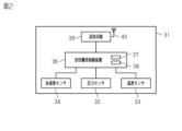
- 2 is a schematic configuration diagram of a transmitter included in the wheel position identification system of FIG. 1.
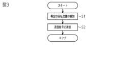
- FIG. 3 is a flowchart showing specific position transmission processing performed by the transmitter of FIG. 2.
- FIG. 2 is a flowchart showing a process performed by the wheel position specifying device of FIG. 1 when determining whether a transmitter is attached to a front wheel or a rear wheel.
- 2 is a flowchart showing a wheel position specifying process performed by the wheel position specifying device of FIG. 1 using ABS.
- 2 is a flowchart showing a process performed by the wheel position specifying device of FIG. 1 when determining whether a transmitter is attached to a front wheel or a rear wheel.
- vehicle 10 includes a plurality of wheel assemblies 11 and 12. As shown in FIG. 1, vehicle 10 includes a plurality of wheel assemblies 11 and 12. As shown in FIG. Each wheel assembly 11, 12 includes a wheel 13 and a tire 14. The plurality of wheel assemblies 11, 12 include a front wheel 11 and a rear wheel 12. Vehicle 10 is a two-wheeled vehicle. The outer diameter of the front wheel 11 and the outer diameter of the rear wheel 12 are different. For example, the outer diameter of the front wheel 11 and the outer diameter of the rear wheel 12 are different because the tire size of the front wheel 11 and the tire size of the rear wheel 12 are different. The outer diameter of the front wheel 11 may be larger than the outer diameter of the rear wheel 12. The outer diameter of the front wheel 11 may be smaller than the outer diameter of the rear wheel 12.
- the outer diameter of the front wheel 11 is larger than the outer diameter of the rear wheel 12.
- the outer diameter of the front wheel 11 is smaller than the outer diameter of the rear wheel 12.
- Vehicle 10 may be equipped with ABS 20.
- ABS20 is an anti-lock braking system.
- ABS 20 includes wheel speed sensors 21 and 22.
- Wheel speed sensors 21 and 22 detect pulses generated when wheel assemblies 11 and 12 rotate. A predetermined number of pulses occur during one revolution of the wheel assemblies 11, 12.
- the wheel speed sensors 21 and 22 include a first wheel speed sensor 21 and a second wheel speed sensor 22.
- the first wheel speed sensor 21 is provided corresponding to the front wheel 11 .
- the first wheel speed sensor 21 detects a pulse generated when the front wheel 11 rotates.
- the second wheel speed sensor 22 is provided corresponding to the rear wheel 12.
- the second wheel speed sensor 22 detects pulses generated when the rear wheel 12 rotates.
- the ABS 20 includes an ABS controller 23.
- the ABS controller 23 is configured by, for example, a microcomputer.
- the ABS controller 23 acquires pulses from the wheel speed sensors 21 and 22.
- the ABS controller 23 counts the falling and rising pulses of each wheel speed sensor 21 and 22. The value obtained thereby is the pulse count number.
- the ABS controller 23 calculates the remainder when the pulse count obtained by counting is divided by the pulse count for one rotation of the wheel assemblies 11 and 12 as a pulse count value. By knowing how many times the wheel assemblies 11, 12 have rotated per pulse count value 1, the rotation angle of the wheel assemblies 11, 12 can be calculated from the pulse count value.
- the pulse count value is information indicating the rotation angle of the wheel assemblies 11 and 12.
- the vehicle 10 is equipped with a wheel position identification system 30.
- the wheel position identification system 30 includes a transmitter 31 .
- the transmitter 31 is attached to each of the front wheel 11 and the rear wheel 12.
- the transmitter 31 may be attached to each wheel assembly 11, 12 by being integrally provided with a tire valve.
- the transmitter 31 may be attached to the tire 14 of each wheel assembly 11, 12.
- the transmitter 31 includes a pressure sensor 32.
- the pressure sensor 32 detects the internal pressure of the corresponding tire 14.
- the transmitter 31 includes a temperature sensor 33.
- Temperature sensor 33 detects the temperature within the corresponding tire 14 .
- the transmitter 31 includes an acceleration sensor 34.
- the acceleration sensor 34 is attached to the wheel assemblies 11, 12 so as to be able to detect the centrifugal force generated by the rotation of the wheel assemblies 11, 12.
- the acceleration sensor 34 includes a detection shaft 35.
- the acceleration sensor 34 detects acceleration in the direction in which the detection shaft 35 extends.
- the acceleration sensor 34 is attached to the wheel assemblies 11, 12 so that the detection axis 35 points vertically upward when the transmitter 31 is located at the top of the wheel assemblies 11, 12.
- the transmitter 31 includes a transmitter control device 36.
- the transmitter control device 36 includes a processor 37 and a transmitter storage section 38.
- Examples of the processor 37 include an MPU (Micro Processing Unit), a CPU (Central Processing Unit), and a DSP (Digital Signal Processor).
- the transmitter storage unit 38 includes a RAM (Random Access Memory) and a ROM (Read Only Memory).
- the transmitter storage unit 38 stores program codes or instructions configured to cause the processor 37 to perform processing.
- the transmitter control device 36 may be configured by a hardware circuit such as an ASIC (Application Specific Integrated Circuit) or an FPGA (Field Programmable Gate Array).
- the transmitter controller 36 which is a processing circuit, may include one or more processors operating according to a computer program, one or more hardware circuits such as ASIC or FPGA, or a combination thereof.
- ROM and RAM or computer readable media include any available media that can be accessed by a general purpose or special purpose computer.
- the transmitter storage unit 38 stores an ID code indicating unique identification information of the corresponding transmitter 31.
- the ID code of the transmitter 31 attached to the front wheel 11 and the ID code of the transmitter 31 attached to the rear wheel 12 are different. Let the ID code of the transmitter 31 attached to the front wheel 11 be the first code. The ID code of the transmitter 31 attached to the rear wheel 12 is defined as a second code.
- the transmitter control device 36 generates transmission data.
- the transmission data is digital data and is binary data.
- the transmitted data includes pressure data, temperature data, and ID code.
- the pressure data is data indicating the pressure detected by the pressure sensor 32.
- the temperature data is data indicating the temperature detected by the temperature sensor 33.
- the transmitter 31 includes a transmitting circuit 39 .
- the transmission circuit 39 performs modulation according to the transmission data input from the transmitter control device 36.
- the transmitter 31 includes a transmitting antenna 40 .
- the transmitter circuit 39 transmits a transmit signal, which is a wireless signal modulated according to the transmit data, from the transmit antenna 40 .
- the transmission circuit 39 transmits a transmission signal including the ID code.
- the transmission signal is a signal in a predetermined frequency band. Examples of frequency bands include LF band, MF band, HF band, VHF band, UHF band, and 2.4 GHz band.
- the transmission signal transmitted from the transmitter 31 mounted on the front wheel 11 is referred to as a first transmission signal.
- the transmission signal transmitted from the transmitter 31 mounted on the rear wheel 12 is referred to as a second transmission signal.
- the transmitter control device 36 performs specific position transmission processing.
- the specific position transmission process is performed, for example, when the vehicle 10 starts traveling after the vehicle 10 has been stopped for a predetermined period of time or more.
- the predetermined time is, for example, several tens of minutes to several hours.
- Whether or not the vehicle 10 is traveling can be determined from the acceleration detected by the acceleration sensor 34. As the vehicle speed increases, the centrifugal acceleration acting on the acceleration sensor 34 increases. If the acceleration detected by the acceleration sensor 34 is greater than or equal to the running determination threshold, the transmitter control device 36 determines that the vehicle 10 is running. If the acceleration detected by the acceleration sensor 34 is less than the running determination threshold, the transmitter control device 36 determines that the vehicle 10 is stopped.
- the running determination threshold value is set to a value larger than the acceleration detected by the acceleration sensor 34 when the vehicle 10 is stopped, taking into account tolerances and the like. The processing performed by the transmitter control device 36 when performing the specific position transmission processing will be described below.
- step S1 the transmitter control device 36 detects that the transmitter 31 is located at a specific rotational position of the wheel assemblies 11, 12.
- the fact that the transmitter 31 is located at a particular rotational position can be detected by the acceleration detected by the acceleration sensor 34.
- Centrifugal acceleration and gravitational acceleration act on the detection shaft 35.
- gravitational acceleration always acts in a vertically downward direction.
- the direction of the detection shaft 35 changes as the wheel assemblies 11 and 12 rotate. Therefore, the gravitational acceleration component detected by the acceleration sensor 34 changes as the wheel assemblies 11 and 12 rotate.
- the centrifugal acceleration changes only slightly during one revolution of the wheel assemblies 11, 12. Therefore, the change in acceleration detected by the acceleration sensor 34 during one rotation of the wheel assemblies 11, 12 can be considered as a change in the gravitational acceleration component due to the change in the direction of the detection shaft 35.
- the gravitational acceleration component detected by the acceleration sensor 34 changes between +1 [G] and -1 [G] while the wheel assemblies 11 and 12 make one rotation.
- the gravitational acceleration component detected when the detection axis 35 points vertically downward is +1 [G].
- the acceleration sensor 34 when the position of the acceleration sensor 34 changes from a position where the detection axis 35 faces vertically downward to a position where the detection axis 35 faces vertically upward, the acceleration sensor 34 The acceleration detected by this decreases. On the other hand, if the position of the acceleration sensor 34 changes from a position where the detection axis 35 faces vertically upward to a position where the detection axis 35 faces vertically downward, the acceleration sensor 34 detects The applied acceleration increases.
- the transmitter control device 36 acquires the detection results of the acceleration sensor 34 at predetermined intervals. The transmitter control device 36 compares the detection result of the acceleration sensor 34 with the previous value every time it obtains the detection result.
- a case where the detection result of the acceleration sensor 34 has increased from the previous value is considered as an increase, and a case where the detection result of the acceleration sensor 34 has decreased from the previous value is considered a decrease.
- the transmitter controller 36 determines that the transmitter 31 is located at a particular rotational position of the wheel assemblies 11, 12 when the pattern of decreases and increases is a predetermined pattern. For example, the transmitter control device 36 determines that the transmitter 31 is located at a specific rotational position when the detection result of the acceleration sensor 34 changes from decreasing to increasing. Thereby, the transmitter control device 36 detects that the transmitter 31 is located at a specific rotational position of the wheel assemblies 11, 12.
- the transmitter control device 36 transmits a transmission signal from the transmission circuit 39.
- the transmitter control device 36 can send a signal from the transmitter circuit 39 when it detects that the transmitter 31 is located at a specific rotational position of the wheel assemblies 11, 12. It is possible to send a signal.
- the specific rotational position in this embodiment is a position where the detection axis 35 faces vertically upward.
- the specific rotational position is a predetermined range that allows for error. Due to various factors, errors occur in the position of the transmitter 31 when the transmitter control device 36 detects a specific rotational position. The various factors include the frequency with which the transmitter control device 36 acquires the detection results of the acceleration sensor 34 and the detection error of the acceleration sensor 34 .
- the "specific rotational position" allows for these errors.
- the specific rotational position can also be said to be a specific range that includes a tolerance range that allows for errors.
- the wheel position identification system 30 includes a wheel position identification device 50.
- the wheel position specifying device 50 is mounted on the vehicle 10.
- the wheel position specifying device 50 is provided, for example, on the vehicle body.
- the wheel position specifying device 50 includes a specifying device control device 51.
- the specific device control device 51 includes a processor 52 and a specific device storage unit 53. Examples of the processor 52 include an MPU, a CPU, and a DSP.
- the specific device storage unit 53 includes a ROM, a RAM, and a rewritable nonvolatile storage medium.
- the specific device storage unit 53 stores program codes or instructions configured to cause the processor 52 to execute processes.
- the specific device control device 51 may be configured by a hardware circuit such as ASIC or FPGA.
- the specific device control device 51 which is a processing circuit, may include one or more processors that operate according to a computer program, one or more hardware circuits such as ASIC or FPGA, or a combination thereof.
- ROM and RAM or computer readable media include any available media that can be accessed by a general purpose or special purpose computer.
- the specific device control device 51 is configured to be able to acquire a pulse count value from the ABS controller 23.
- the wheel position identifying device 50 includes a receiving antenna 54 .
- the receiving antenna 54 receives the transmission signal transmitted from each transmitter 31.
- the wheel position specifying device 50 includes a receiving circuit 55.
- the reception circuit 55 obtains transmission data by demodulating the transmission signal received via the reception antenna 54.
- the receiving circuit 55 outputs transmission data to the specific device control device 51.
- the specific device control device 51 acquires the pressure data, temperature data, and ID code.
- the specific device control device 51 can determine whether or not an abnormality has occurred in the tire 14.
- the specific device control device 51 can determine whether an abnormality has occurred in the internal pressure of the tire 14 from the pressure data.
- the specific device control device 51 can determine whether or not there is an abnormality in the temperature inside the tire 14 from the temperature data.
- the specific device control device 51 may provide notification via the display unit when an abnormality has occurred in the tire 14.
- the display section is arranged, for example, at a position that is visible to a passenger of the vehicle 10.
- the specifying device control device 51 performs wheel position specifying processing.
- the wheel position specifying process is to associate each wheel assembly 11, 12 with the ID code of each transmitter 31.
- the correspondence between each wheel assembly 11, 12 and the ID code of each transmitter 31 can also be said to specify whether each of the two transmitters 31 is attached to the front wheel 11 or the rear wheel 12. .
- the specific device control device 51 associates the pressure of the tire 14 with the position of the wheel assembly 11, 12 and displays it on the display section. can be displayed. Further, when an abnormality occurs in the tire 14, the specific device control device 51 can display the position of the tire 14 where the abnormality has occurred on the display section.
- the wheel position specifying process is performed, for example, when the vehicle 10 is changed from a stopped state to a started state by operating a start switch.
- the start switch is also called the ignition switch.
- the transmission signal is transmitted by specific position transmission processing.
- the wheel position specifying process is performed by the specifying device control device 51, so that it is specified whether each of the transmitters 31 is attached to the front wheel 11 or the rear wheel 12 by the wheel position specifying method.
- the specific device control device 51 determines the rotation period [msec] of the front wheel 11.
- the specific device control device 51 may calculate the rotation period of the front wheel 11 from the outer diameter of the front wheel 11 and the speed of the vehicle 10.
- the outer diameter of the front wheel 11 is stored in the specific device storage unit 53, for example.
- the speed of the vehicle 10 can be obtained from the ABS controller 23, for example.
- the specific device control device 51 may determine the rotation period of the front wheels 11 using data that associates the rotation period of the front wheels 11 with the speed of the vehicle 10. If the outer diameter of the front wheel 11 is known in advance, the rotation period of the front wheel 11 corresponding to the speed of the front wheel 11 can be calculated in advance. By storing the calculated data in the specific device storage unit 53, the specific device control device 51 can determine the rotation period of the front wheels 11 from the speed of the vehicle 10.
- step S12 the specific device control device 51 determines the rotation period [msec] of the rear wheel 12.
- the rotation period of the rear wheel 12 can be determined using the same method as the rotation period of the front wheel 11.
- the specific device control device 51 may calculate the rotation period of the rear wheel 12 from the outer diameter of the rear wheel 12 and the speed of the vehicle 10, or may calculate the rotation period of the rear wheel 12 from the speed of the vehicle 10.
- the rotation period of the rear wheel 12 may be determined using .
- step S13 the specific device control device 51 acquires the transmission data demodulated by the reception circuit 55 receiving the transmission signal.
- step S14 the specific device control device 51 calculates the reception interval [msec] of the transmission signal for each ID code.
- the specific device control device 51 acquires the ID code from the transmission data, it calculates the elapsed time since the last acquisition of transmission data containing the same ID code as the ID code. Thereby, the reception interval of the transmission signal can be calculated for each ID code.
- the specific device control device 51 acquires the transmission data including the first code, it calculates the elapsed time since the last acquisition of the transmission data including the first code, thereby determining the reception of the first transmission signal. Calculate the interval.
- the specific device control device 51 acquires the transmission data including the second code, it calculates the elapsed time since the last acquisition of the transmission data including the second code, thereby determining the reception of the second transmission signal. Calculate the interval.
- the specific device control device 51 determines the transmitter 31 attached to the front wheel 11. If the difference between the reception interval of the first transmission signal and the rotation period of the front wheel 11 is smaller than the difference between the reception interval of the second transmission signal and the rotation period of the front wheel 11, the specific device control device 51 transmits the first transmission signal. It is determined that the transmitter 31 that transmitted the signal is attached to the front wheel 11. That is, the specific device control device 51 selects the transmitter mounted on the front wheel 11 to transmit the transmission signal with the smaller difference between the reception interval and the rotation period of the front wheel 11 out of two types of transmission signals with different reception intervals. It is determined that the signal is the first transmission signal transmitted from No. 31. Thereby, the specific device control device 51 can specify the transmitter 31 attached to the front wheel 11, and can associate the first code with the front wheel 11.
- the specific device control device 51 determines the transmitter 31 attached to the rear wheel 12. If the difference between the reception interval of the second transmission signal and the rotation period of the rear wheel 12 is smaller than the difference between the reception interval of the first transmission signal and the rotation period of the rear wheel 12, the specific device control device 51 It is determined that the transmitter 31 that transmitted the 2 transmission signal is attached to the rear wheel 12. That is, the specific device control device 51 selects the transmission signal that has a smaller difference between the reception interval and the rotation period of the rear wheel 12 from among the two types of transmission signals with different reception intervals, which is attached to the rear wheel 12. It is determined that it is the second transmission signal transmitted from the transmitter 31. Thereby, the specific device control device 51 can specify the transmitter 31 attached to the rear wheel 12 and can associate the second code with the rear wheel 12.
- step S17 the specific device control device 51 stores the correspondence between the ID code and the wheel assemblies 11 and 12 in the specific device storage section 53. After completing the process in step S17, the specific device control device 51 ends the wheel position specifying process.
- the transmitter 31 transmits a transmission signal at a specific rotational position of the wheel assemblies 11 and 12.
- the time from when the transmitter 31 is positioned at a specific rotational position of the wheel assemblies 11, 12 to when the transmitter 31 is positioned at the next specific rotational position of the wheel assemblies 11, 12 corresponds to the rotation period of If the transmitter 31 is attached to the front wheel 11, the state in which the transmitter 31 is located at a specific rotational position of the front wheel 11 until the transmitter 31 is located at the next specific rotational position of the front wheel 11 is The time corresponds to the rotation period of the front wheel 11. Therefore, the transmission interval of the first transmission signal depends on the rotation period of the front wheel 11. Similarly, the transmission interval of the second transmission signal depends on the rotation period of the rear wheel 12.
- the specific device control device 51 determines whether each of the transmitters 31 is attached to the front wheel 11 or not from the reception interval of the first transmission signal and the reception interval of the second transmission signal. It can be determined whether the device is attached to the device.
- the specific device control device 51 determines that among the two types of transmission signals with different reception intervals, the transmission signal with the smaller difference between the reception interval and the rotation period of the front wheel 11 is the first transmission signal. judge.
- the transmission interval of the transmission signal from the transmitter 31 attached to the front wheel 11 depends on the rotation period of the front wheel 11. Therefore, the difference between the reception interval of the transmission signal from the transmitter 31 mounted on the front wheel 11 and the rotation period of the front wheel 11 is the difference between the reception interval of the transmission signal from the transmitter 31 mounted on the rear wheel 12 and the rotation period of the front wheel 11. is smaller than the difference between the rotation period of Thereby, the specific device control device 51 can determine that the transmission signal with the smaller difference between the reception interval and the rotation period of the front wheel 11 is the first transmission signal among the two types of transmission signals with different reception intervals. .
- a second embodiment of a wheel position specifying device, a wheel position specifying system, and a wheel position specifying method will be described.
- the processing performed by the specific device control device is different from the first embodiment.
- the wheel position specifying process of the first embodiment and the wheel position specifying process using ABS are used together.
- step S21 the specific device control device 51 converts the pulse count values of each wheel speed sensor 21, 22 into the ABS every time transmission data is acquired, in other words, every time a transmission signal is received. Obtained from the controller 23.
- the specific device control device 51 performs position determination.
- the position determination is to determine whether each transmitter 31 is attached to the front wheel 11 or the rear wheel 12. Position determination is performed by acquiring a pulse count value each time transmission data is acquired. If the transmitter 31 is transmitting a transmission signal at a particular rotational position, the rotation angle of each of the two wheel assemblies 11, 12 is the rotation at which the transmission signal is transmitted from either of the two transmitters 31. synchronized with the angle. Therefore, when each transmitter 31 transmits a transmission signal at a specific rotational position, when a pulse count value is obtained upon reception of the transmission signal, a wheel with a small variation in pulse count value corresponds to each transmitter 31. Speed sensors 21, 22 are present.
- the specific device control device 51 determines which of the wheel assemblies 11 and 12 each transmitter 31 is attached to from the variation in pulse count values collected each time transmission data is acquired. That is, the specific device control device 51 allows each transmitter 31 to control the wheel assembly 11 based on the variation in the rotation angle of the front wheel 11 when receiving the transmission signal and the variation in the rotation angle of the rear wheel 12 when receiving the transmission signal. , 12 to which it is attached.
- the specific device control device 51 collects pulse count values for each wheel speed sensor 21 and 22 every time the receiving circuit 55 receives a transmission signal. When the collected pulse count value falls within a predetermined range, the specific device control device 51 associates the transmitter 31 with the wheel assemblies 11 and 12 corresponding to the wheel speed sensors 21 and 22 that detected the pulse count value.
- the predetermined range is a range that is set in consideration of variations in pulse count values, and is used to determine which wheel speed sensors 21 and 22 have less variation in pulse count values. Thereby, the specific device control device 51 can use the ABS 20 to determine whether each of the transmitters 31 is attached to the front wheel 11 or the rear wheel 12.
- the specific device control device 51 acquires the pulse count values of the wheel speed sensors 21 and 22 every time the specific device control device 51 acquires transmission data including the first code.
- the variation in the pulse count value of the first wheel speed sensor 21 is smaller than the variation in the pulse count value of the second wheel speed sensor 22. Therefore, it can be determined that the transmitter 31 of the first code is attached to the front wheel 11.
- the specific device control device 51 repeatedly performs the processes of step S21 and step S22 until the ID code of each transmitter 31 and the wheel assemblies 11, 12 are associated with each other.
- the specific device control device 51 determines whether each of the transmitters 31 is attached to the front wheel 11 or not by performing the processing in steps S11 to S17, as in the first embodiment. It is determined whether it is attached to the wheel 12. Through the processing in steps S11 to S17, a determination result of the wheel position specifying process based on the reception interval of the first transmission signal and the reception interval of the second transmission signal is obtained.
- the wheel position identification process based on the reception interval of the first transmission signal and the reception interval of the second transmission signal is referred to as the first wheel position identification process.
- the specific device control device 51 After completing the processing in steps S11 to S17, the specific device control device 51 performs the processing in step S18. If the specific device control device 51 cannot determine whether each of the transmitters 31 is attached to the front wheel 11 or the rear wheel 12 through the processing in steps S11 to S17, the specific device control device 51 executes the processing in step S18. You may do so.
- step S18 the specific device control device 51 determines whether the wheel position specifying process using the ABS 20 is completed. If the determination result in step S18 is negative, the specific device control device 51 performs the determination in step S18 again. If the determination result in step S18 is affirmative, the specific device control device 51 performs the process in step S19. It can be said that the specific device control device 51 repeats the determination in step S18 until the determination result in step S18 becomes affirmative.
- the wheel position specifying process using the ABS 20 is referred to as the second wheel position specifying process.
- step S19 the specific device control device 51 updates the correspondence between the ID code and the wheel assemblies 11 and 12.
- the identification device control device 51 determines whether each of the transmitters 31 is attached to the front wheel 11 or the rear wheel 12 based on the determination result of the first wheel position determination process and the determination result of the second wheel position determination process. Determine whether it is installed.
- the specifying device control device 51 gives priority to the determination result of the second wheel position specifying process. That is, the identification device control device 51 updates the correspondence between the ID code and the wheel assemblies 11 and 12 with the determination result of the second wheel position identification process, regardless of the determination result of the first wheel position identification process.
- the identification device control device 51 identifies the ID code and the wheel assembly 11, 12 based on the matched determination result. The correspondence relationship may be updated. If the determination result of the first wheel position specifying process and the determination result of the second wheel position specifying process do not match, the specifying device control device 51 executes the first wheel position specifying process and the second wheel position specifying process. You may try again.
- the identification device control device 51 determines whether each of the transmitters 31 is attached to the front wheel 11 based on the determination result of the first wheel position identification process and the determination result of the second wheel position identification process. It is determined whether the vehicle is attached to the rear wheel 12 or not.
- the second wheel position specifying process has higher accuracy in determining which wheel assembly 11, 12 the transmitter 31 is attached to than the first wheel position specifying process.
- the first wheel position specifying process takes less time than the second wheel position specifying process to determine which wheel assembly 11 or 12 the transmitter 31 is attached to.
- the determination result of the first wheel position specifying process is used until the second wheel position specifying process is completed, and the determination result of the second wheel position specifying process is used after the second wheel position specifying process is completed. I am using it. This reduces the time required to determine which wheel assembly 11, 12 the transmitter 31 is attached to, and the accuracy of determining which wheel assembly 11, 12 the transmitter 31 is attached to. It is possible to achieve both improvements in
- the outer diameter of the front wheel 11 and the outer diameter of the rear wheel 12 may become the same. In this case, it cannot be determined by the first wheel position specifying process whether each of the transmitters 31 is attached to the front wheel 11 or the rear wheel 12.
- the first wheel position specifying process and the second wheel position specifying process it is not possible to determine whether each of the transmitters 31 is attached to the front wheel 11 or the rear wheel 12 by the first wheel position specifying process. Even in this case, it is possible to determine whether each transmitter 31 is attached to the front wheel 11 or the rear wheel 12 by the second wheel position specifying process.
- the ABS 20 may include wheel speed sensors 21 and 22 corresponding to one of the front wheels 11 and the rear wheels 12.
- the ABS 20 may include a first wheel speed sensor 21 corresponding to the front wheel 11 and may not include a second wheel speed sensor 22 corresponding to the rear wheel 12.
- the specific device control device 51 may only determine which of the two transmitters 31 is attached to the front wheel 11 by the second wheel position specifying process. can. When the specific device control device 51 determines which of the two transmitters 31 is attached to the front wheel 11, it may determine that the remaining transmitters 31 are attached to the rear wheel 12.
- the specific device control device 51 may determine that the remaining one transmitter 31 is attached to the rear wheel 12. Similarly, the specific device control device 51 determines which transmitter 31 is attached to the rear wheel 12 based on the rotation period of the rear wheel 12, and determines that the remaining transmitters 31 are attached to the front wheel 11. Good too.
- the specific device control device 51 determines whether each of the transmitters 31 is attached to the front wheel 11 by comparing the reception interval of the first transmission signal and the reception interval of the second transmission signal. 12 may be determined. When the outer diameter of the front wheel 11 is larger than the outer diameter of the rear wheel 12, the reception interval of the first transmission signal is longer than the reception interval of the second transmission signal. In this case, the specific device control device 51 can determine that the transmitter 31 that has transmitted the transmission signal with a long reception interval is attached to the front wheel 11. The specific device control device 51 can determine that the transmitter 31 that has transmitted the transmission signal with a short reception interval is attached to the rear wheel 12.
- the specific device control device 51 can determine that the transmitter 31 that has transmitted the transmission signal with a short reception interval is attached to the front wheel 11.
- the specific device control device 51 can determine that the transmitter 31 that has transmitted the transmission signal with a long reception interval is attached to the rear wheel 12. Whether the outer diameter of the front wheel 11 is larger or smaller than the outer diameter of the rear wheel 12 may be stored in the specific device storage section 53.
- the vehicle 10 may be a four-wheeled vehicle as long as the outer diameter of the front wheels 11 and the outer diameter of the rear wheels 12 are different.
- "two types of transmission signals with different reception intervals" means two types of transmission signals whose reception intervals are substantially different due to a difference in the outer diameter of the wheel assembly. Although there may be slight differences in the reception intervals of the respective transmission signals transmitted from two wheel assemblies of substantially equal outer diameter, such differences are within the tolerance range and the actual reception interval It is not included in the difference.
- the specifying device control device 51 may give priority to the determination result of the first wheel position specifying process.
- the identification device control device 51 may use the determination result of the second wheel position identification process when the determination cannot be made by the first wheel position identification process.
Abstract
A vehicle (10) is provided with a front wheel (11) and a rear wheel (12) having mutually different outer diameters. A wheel position identifying device (50) is provided with: a reception circuit (55) configured to receive a first transmission signal which is transmitted from a transmitter (31) fitted to the front wheel (11) and which is transmitted at a specific rotational position of the front wheel (11), and a second transmission signal which is transmitted from a transmitter (31) fitted to the rear wheel (12) and which is transmitted at a specific rotational position of the rear wheel (12); and a specific device control device (51). The specific device control device (51) is configured to determine, from a reception interval of the first transmission signal and a reception interval of the second transmission signal, whether each transmitter (31) is fitted to the front wheel (11) or is fitted to the rear wheel (12).
Description
本開示は、輪位置特定装置、輪位置特定システム、及び輪位置特定方法に関する。
The present disclosure relates to a wheel position identification device, a wheel position identification system, and a wheel position identification method.
特許文献1に開示のタイヤ状態監視システムは、送信機と、受信機と、を備える。タイヤ状態監視システムは、車両に搭載される。車両は、複数のホイールアセンブリを備える。ホイールアセンブリは、車輪と、タイヤと、を備える。送信機は、複数のホイールアセンブリのそれぞれに設けられている。送信機は、タイヤの状態を検出する。タイヤの状態は、例えば、タイヤの内圧である。送信機は、送信信号を受信機に送信する。受信機は、送信信号を受信することによって、タイヤの状態を認識する。
The tire condition monitoring system disclosed in Patent Document 1 includes a transmitter and a receiver. A tire condition monitoring system is mounted on a vehicle. The vehicle includes multiple wheel assemblies. The wheel assembly includes a wheel and a tire. A transmitter is provided in each of the plurality of wheel assemblies. The transmitter detects the condition of the tires. The condition of the tire is, for example, the internal pressure of the tire. A transmitter transmits a transmission signal to a receiver. The receiver recognizes the condition of the tire by receiving the transmitted signal.
受信機は、複数のホイールアセンブリのそれぞれに設けられた送信機からの送信信号を受信する。受信した送信信号が複数のホイールアセンブリのうちいずれの送信機から送信されたものであるかを、受信機に判定させたい場合がある。
The receiver receives transmission signals from transmitters provided in each of the plurality of wheel assemblies. It may be desirable for the receiver to determine from which transmitter of a plurality of wheel assemblies a received transmission signal was transmitted.
本開示の第一の態様によれば、前輪及び後輪を備える車両に搭載される輪位置特定装置が提供される。前記前輪の外径と前記後輪の外径とは異なる。前記輪位置特定装置は、前記前輪に装着された送信機から送信される第1送信信号であって前記前輪の回転位置の特定の回転位置で送信される第1送信信号、及び前記後輪に装着された送信機から送信される第2送信信号であって前記後輪の回転位置の特定の回転位置で送信される第2送信信号を受信するように構成される受信回路と、特定装置用制御装置と、を備える。前記特定装置用制御装置は、前記第1送信信号の受信間隔及び、前記第2送信信号の受信間隔から前記送信機の各々が前記前輪に装着されているか前記後輪に装着されているかを判定するように構成される。
According to a first aspect of the present disclosure, a wheel position specifying device mounted on a vehicle including front wheels and rear wheels is provided. The outer diameter of the front wheel and the outer diameter of the rear wheel are different. The wheel position specifying device includes a first transmission signal transmitted from a transmitter attached to the front wheel at a specific rotational position of the front wheel, and a first transmission signal transmitted from a transmitter attached to the front wheel, and a first transmission signal transmitted from a transmitter attached to the front wheel. a receiving circuit configured to receive a second transmission signal transmitted from a mounted transmitter and transmitted at a specific rotational position of the rear wheel; A control device. The specific device control device determines whether each of the transmitters is attached to the front wheel or the rear wheel from the reception interval of the first transmission signal and the reception interval of the second transmission signal. configured to do so.
前輪の外径と後輪の外径とが異なると、前輪の回転周期と後輪の回転周期とが異なる。第1送信信号の送信間隔は、前輪の回転周期に依存する。第2送信信号の送信間隔は、後輪の回転周期に依存する。特定装置用制御装置は、前輪の外径と後輪の外径との差異による送信信号の受信間隔の差異を利用することで、送信機の各々が前輪に装着されているか、後輪に装着されているかを判定することができる。
If the outer diameter of the front wheel and the outer diameter of the rear wheel are different, the rotation period of the front wheel and the rotation period of the rear wheel will be different. The transmission interval of the first transmission signal depends on the rotation period of the front wheel. The transmission interval of the second transmission signal depends on the rotation period of the rear wheel. The specific device control device uses the difference in the reception interval of transmission signals due to the difference between the outer diameter of the front wheel and the outer diameter of the rear wheel to determine whether each transmitter is attached to the front wheel or the rear wheel. It is possible to determine whether the
上記輪位置特定装置について、前記特定装置用制御装置は、前記前輪の外径及び前記車両の速度から前記前輪の回転周期を求め、受信間隔の異なる2種類の送信信号のうち、受信間隔と前記回転周期との差が小さい方の送信信号が、前記前輪に装着されている送信機から送信された前記第1送信信号であると判定するように構成されてもよい。
Regarding the wheel position identification device, the identification device control device determines the rotation period of the front wheel from the outer diameter of the front wheel and the speed of the vehicle, and determines the rotation period of the front wheel from the outer diameter of the front wheel and the speed of the vehicle, and selects the reception interval and the The transmission signal may be configured to determine that the transmission signal having a smaller difference from the rotation period is the first transmission signal transmitted from a transmitter attached to the front wheel.
上記輪位置特定装置について、前記特定装置用制御装置は、前記第1送信信号及び前記第2送信信号のそれぞれを受信する度に前記前輪の回転角度を示す情報、及び前記後輪の回転角度を示す情報を取得し、前記前輪の回転角度のばらつき、及び前記後輪の回転角度のばらつきから前記送信機の各々が前記前輪に装着されているか前記後輪に装着されているかを判定し、前記第1送信信号の受信間隔及び前記第2送信信号の受信間隔に基づく判定結果と、前記前輪の回転角度のばらつき及び前記後輪の回転角度のばらつきに基づく判定結果と、に基づいて前記送信機の各々が前記前輪に装着されているか前記後輪に装着されているかを特定するように構成されていてもよい。
Regarding the wheel position specifying device, the specifying device control device transmits information indicating the rotation angle of the front wheel and information indicating the rotation angle of the rear wheel each time it receives each of the first transmission signal and the second transmission signal. determine whether each of the transmitters is attached to the front wheel or the rear wheel from the variation in the rotation angle of the front wheels and the variation in the rotation angle of the rear wheels; The transmitter transmits the transmitter based on the determination result based on the reception interval of the first transmission signal and the reception interval of the second transmission signal, and the determination result based on the variation in the rotation angle of the front wheels and the variation in the rotation angle of the rear wheels. It may be configured to specify whether each of the above is attached to the front wheel or the rear wheel.
本開示の第二の態様によれば、前輪及び後輪を備える車両に搭載される輪位置特定システムが提供される。前記前輪の外径と前記後輪の外径とは異なる。前記輪位置特定システムは、前記前輪及び前記後輪のそれぞれに装着される送信機と、輪位置特定装置と、を備える。前記輪位置特定装置は、前記前輪に装着された送信機から送信される第1送信信号であって前記前輪の回転位置の特定の回転位置で送信される第1送信信号、及び前記後輪に装着された送信機から送信される第2送信信号であって前記後輪の回転位置の特定の回転位置で送信される第2送信信号を受信するように構成される受信回路と、特定装置用制御装置と、を備える。前記特定装置用制御装置は、前記第1送信信号の受信間隔及び、前記第2送信信号の受信間隔から前記送信機の各々が前記前輪に装着されているか前記後輪に装着されているかを判定するように構成される。
According to a second aspect of the present disclosure, a wheel position identification system mounted on a vehicle including front wheels and rear wheels is provided. The outer diameter of the front wheel and the outer diameter of the rear wheel are different. The wheel position specifying system includes a transmitter attached to each of the front wheel and the rear wheel, and a wheel position specifying device. The wheel position specifying device includes a first transmission signal transmitted from a transmitter attached to the front wheel at a specific rotational position of the front wheel, and a first transmission signal transmitted from a transmitter attached to the front wheel, and a first transmission signal transmitted from a transmitter attached to the front wheel. a receiving circuit configured to receive a second transmission signal transmitted from a mounted transmitter and transmitted at a specific rotational position of the rear wheel; A control device. The specific device control device determines whether each of the transmitters is attached to the front wheel or the rear wheel from the reception interval of the first transmission signal and the reception interval of the second transmission signal. configured to do so.
前輪の外径と後輪の外径とが異なると、前輪の回転周期と後輪の回転周期とが異なる。第1送信信号の送信間隔は、前輪の回転周期に依存する。第2送信信号の送信間隔は、後輪の回転周期に依存する。特定装置用制御装置は、前輪の外径と後輪の外径との差異による送信信号の受信間隔の差異を利用することで、送信機の各々が前輪に装着されているか、後輪に装着されているかを判定することができる。
If the outer diameter of the front wheel and the outer diameter of the rear wheel are different, the rotation period of the front wheel and the rotation period of the rear wheel will be different. The transmission interval of the first transmission signal depends on the rotation period of the front wheel. The transmission interval of the second transmission signal depends on the rotation period of the rear wheel. The specific device control device uses the difference in the reception interval of transmission signals due to the difference between the outer diameter of the front wheel and the outer diameter of the rear wheel to determine whether each transmitter is attached to the front wheel or the rear wheel. It is possible to determine whether the
本開示の第三の態様によれば、前輪及び後輪を備える車両のための輪位置特定方法が提供される。前記前輪の外径と前記後輪の外径とは異なる。前記輪位置特定方法は、前記前輪に装着された送信機から送信される第1送信信号であって前記前輪の特定の回転位置で送信される第1送信信号を受信することと、前記後輪に装着された送信機から送信される第2送信信号であって前記後輪の特定の回転位置で送信される第2送信信号を受信することと、前記第1送信信号の受信間隔及び、前記第2送信信号の受信間隔から前記送信機の各々が前記前輪に装着されているか前記後輪に装着されているかを判定することと、を備える。
According to a third aspect of the present disclosure, a wheel positioning method for a vehicle including front wheels and rear wheels is provided. The outer diameter of the front wheel and the outer diameter of the rear wheel are different. The wheel position specifying method includes the steps of: receiving a first transmission signal transmitted from a transmitter attached to the front wheel, the first transmission signal being transmitted at a specific rotational position of the front wheel; receiving a second transmission signal transmitted from a transmitter mounted on the rear wheel at a specific rotational position of the rear wheel; and determining the reception interval of the first transmission signal; determining whether each of the transmitters is attached to the front wheel or the rear wheel from the reception interval of the second transmission signal.
前輪の外径と後輪の外径とが異なると、前輪の回転周期と後輪の回転周期とが異なる。第1送信信号の送信間隔は、前輪の回転周期に依存する。第2送信信号の送信間隔は、後輪の回転周期に依存する。輪位置特定方法は、前輪の外径と後輪の外径との差異による送信信号の受信間隔の差異を利用することで、送信機の各々が前輪に装着されているか、後輪に装着されているかを判定することができる。
If the outer diameter of the front wheel and the outer diameter of the rear wheel are different, the rotation period of the front wheel and the rotation period of the rear wheel will be different. The transmission interval of the first transmission signal depends on the rotation period of the front wheel. The transmission interval of the second transmission signal depends on the rotation period of the rear wheel. The wheel position identification method uses the difference in the reception interval of transmitted signals due to the difference between the outer diameter of the front wheel and the outer diameter of the rear wheel to determine whether each transmitter is attached to the front wheel or the rear wheel. It is possible to determine whether
[第1実施形態]
輪位置特定装置、輪位置特定システム、及び輪位置特定方法の第1実施形態について説明する。 [First embodiment]
A first embodiment of a wheel position specifying device, a wheel position specifying system, and a wheel position specifying method will be described.
輪位置特定装置、輪位置特定システム、及び輪位置特定方法の第1実施形態について説明する。 [First embodiment]
A first embodiment of a wheel position specifying device, a wheel position specifying system, and a wheel position specifying method will be described.
<車両>
図1に示すように、車両10は、複数のホイールアセンブリ11,12を備える。各ホイールアセンブリ11,12は、ホイール13と、タイヤ14と、を備える。複数のホイールアセンブリ11,12は、前輪11及び後輪12を含む。車両10は、二輪車である。前輪11の外径と後輪12の外径とは異なる。例えば、前輪11のタイヤサイズと後輪12のタイヤサイズとが異なることに起因して、前輪11の外径と後輪12の外径とは異なる。前輪11の外径が、後輪12の外径よりも大きくてもよい。前輪11の外径が、後輪12の外径よりも小さくてもよい。例えば、二輪車がデュアルパーパス、又はオフローダーの場合、前輪11の外径が後輪12の外径よりも大きい。例えば、二輪車がスポーツバイク、クルーザー、又はロードレーサーの場合、前輪11の外径が後輪12の外径よりも小さい。 <Vehicle>
As shown in FIG. 1,vehicle 10 includes a plurality of wheel assemblies 11 and 12. As shown in FIG. Each wheel assembly 11, 12 includes a wheel 13 and a tire 14. The plurality of wheel assemblies 11, 12 include a front wheel 11 and a rear wheel 12. Vehicle 10 is a two-wheeled vehicle. The outer diameter of the front wheel 11 and the outer diameter of the rear wheel 12 are different. For example, the outer diameter of the front wheel 11 and the outer diameter of the rear wheel 12 are different because the tire size of the front wheel 11 and the tire size of the rear wheel 12 are different. The outer diameter of the front wheel 11 may be larger than the outer diameter of the rear wheel 12. The outer diameter of the front wheel 11 may be smaller than the outer diameter of the rear wheel 12. For example, when the two-wheeled vehicle is a dual-purpose vehicle or an off-roader, the outer diameter of the front wheel 11 is larger than the outer diameter of the rear wheel 12. For example, when the two-wheeled vehicle is a sports bike, cruiser, or road racer, the outer diameter of the front wheel 11 is smaller than the outer diameter of the rear wheel 12.
図1に示すように、車両10は、複数のホイールアセンブリ11,12を備える。各ホイールアセンブリ11,12は、ホイール13と、タイヤ14と、を備える。複数のホイールアセンブリ11,12は、前輪11及び後輪12を含む。車両10は、二輪車である。前輪11の外径と後輪12の外径とは異なる。例えば、前輪11のタイヤサイズと後輪12のタイヤサイズとが異なることに起因して、前輪11の外径と後輪12の外径とは異なる。前輪11の外径が、後輪12の外径よりも大きくてもよい。前輪11の外径が、後輪12の外径よりも小さくてもよい。例えば、二輪車がデュアルパーパス、又はオフローダーの場合、前輪11の外径が後輪12の外径よりも大きい。例えば、二輪車がスポーツバイク、クルーザー、又はロードレーサーの場合、前輪11の外径が後輪12の外径よりも小さい。 <Vehicle>
As shown in FIG. 1,
車両10は、ABS20を備えていてもよい。ABS20は、アンチロック・ブレーキ・システムである。
ABS20は、車輪速センサ21,22を備える。車輪速センサ21,22は、ホイールアセンブリ11,12が回転することで生じるパルスを検出する。ホイールアセンブリ11,12が1回転する間に、所定回数のパルスが生じる。車輪速センサ21,22は、第1車輪速センサ21と、第2車輪速センサ22と、を含む。第1車輪速センサ21は、前輪11に対応して設けられている。第1車輪速センサ21は、前輪11が回転することで生じるパルスを検出する。第2車輪速センサ22は、後輪12に対応して設けられている。第2車輪速センサ22は、後輪12が回転することで生じるパルスを検出する。Vehicle 10 may be equipped with ABS 20. ABS20 is an anti-lock braking system.
ABS 20 includes wheel speed sensors 21 and 22. Wheel speed sensors 21 and 22 detect pulses generated when wheel assemblies 11 and 12 rotate. A predetermined number of pulses occur during one revolution of the wheel assemblies 11, 12. The wheel speed sensors 21 and 22 include a first wheel speed sensor 21 and a second wheel speed sensor 22. The first wheel speed sensor 21 is provided corresponding to the front wheel 11 . The first wheel speed sensor 21 detects a pulse generated when the front wheel 11 rotates. The second wheel speed sensor 22 is provided corresponding to the rear wheel 12. The second wheel speed sensor 22 detects pulses generated when the rear wheel 12 rotates.
ABS20は、車輪速センサ21,22を備える。車輪速センサ21,22は、ホイールアセンブリ11,12が回転することで生じるパルスを検出する。ホイールアセンブリ11,12が1回転する間に、所定回数のパルスが生じる。車輪速センサ21,22は、第1車輪速センサ21と、第2車輪速センサ22と、を含む。第1車輪速センサ21は、前輪11に対応して設けられている。第1車輪速センサ21は、前輪11が回転することで生じるパルスを検出する。第2車輪速センサ22は、後輪12に対応して設けられている。第2車輪速センサ22は、後輪12が回転することで生じるパルスを検出する。
ABS20は、ABSコントローラ23を備える。ABSコントローラ23は、例えば、マイクロコンピュータ等によって構成されている。ABSコントローラ23は、車輪速センサ21,22からパルスを取得する。ABSコントローラ23は、車輪速センサ21,22毎にパルスの立ち下がりと立ち上がりをカウントする。これにより得られた値をパルスのカウント数とする。ABSコントローラ23は、カウントにより得られたパルスのカウント数を、ホイールアセンブリ11,12の1回転分のパルスのカウント数で除算したときの余りを、パルスカウント値として算出する。パルスカウント値1につき、ホイールアセンブリ11,12が何度回転したかを把握することで、パルスカウント値からホイールアセンブリ11,12の回転角度を算出できる。パルスカウント値は、ホイールアセンブリ11,12の回転角度を示す情報である。
The ABS 20 includes an ABS controller 23. The ABS controller 23 is configured by, for example, a microcomputer. The ABS controller 23 acquires pulses from the wheel speed sensors 21 and 22. The ABS controller 23 counts the falling and rising pulses of each wheel speed sensor 21 and 22. The value obtained thereby is the pulse count number. The ABS controller 23 calculates the remainder when the pulse count obtained by counting is divided by the pulse count for one rotation of the wheel assemblies 11 and 12 as a pulse count value. By knowing how many times the wheel assemblies 11, 12 have rotated per pulse count value 1, the rotation angle of the wheel assemblies 11, 12 can be calculated from the pulse count value. The pulse count value is information indicating the rotation angle of the wheel assemblies 11 and 12.
<輪位置特定システム>
車両10には、輪位置特定システム30が搭載されている。輪位置特定システム30は、送信機31を備える。送信機31は、前輪11及び後輪12のそれぞれに装着される。送信機31は、タイヤバルブに一体に設けられることによって各ホイールアセンブリ11,12に装着されていてもよい。送信機31は、各ホイールアセンブリ11,12のタイヤ14に貼り付けられていてもよい。 <Wheel position identification system>
Thevehicle 10 is equipped with a wheel position identification system 30. The wheel position identification system 30 includes a transmitter 31 . The transmitter 31 is attached to each of the front wheel 11 and the rear wheel 12. The transmitter 31 may be attached to each wheel assembly 11, 12 by being integrally provided with a tire valve. The transmitter 31 may be attached to the tire 14 of each wheel assembly 11, 12.
車両10には、輪位置特定システム30が搭載されている。輪位置特定システム30は、送信機31を備える。送信機31は、前輪11及び後輪12のそれぞれに装着される。送信機31は、タイヤバルブに一体に設けられることによって各ホイールアセンブリ11,12に装着されていてもよい。送信機31は、各ホイールアセンブリ11,12のタイヤ14に貼り付けられていてもよい。 <Wheel position identification system>
The
図2に示すように、送信機31は、圧力センサ32を備える。圧力センサ32は、対応するタイヤ14の内圧を検出する。送信機31は、温度センサ33を備える。温度センサ33は、対応するタイヤ14内の温度を検出する。
As shown in FIG. 2, the transmitter 31 includes a pressure sensor 32. The pressure sensor 32 detects the internal pressure of the corresponding tire 14. The transmitter 31 includes a temperature sensor 33. Temperature sensor 33 detects the temperature within the corresponding tire 14 .
送信機31は、加速度センサ34を備える。加速度センサ34は、ホイールアセンブリ11,12の回転により発生する遠心力を検出できるように、ホイールアセンブリ11,12に装着されている。図1に示すように加速度センサ34は、検出軸35を備える。加速度センサ34は、検出軸35の延びる方向に対する加速度を検出する。例えば、加速度センサ34は、送信機31がホイールアセンブリ11,12の最上位置に位置しているときに検出軸35が鉛直上方向を向くように、ホイールアセンブリ11,12に装着されている。
The transmitter 31 includes an acceleration sensor 34. The acceleration sensor 34 is attached to the wheel assemblies 11, 12 so as to be able to detect the centrifugal force generated by the rotation of the wheel assemblies 11, 12. As shown in FIG. 1, the acceleration sensor 34 includes a detection shaft 35. The acceleration sensor 34 detects acceleration in the direction in which the detection shaft 35 extends. For example, the acceleration sensor 34 is attached to the wheel assemblies 11, 12 so that the detection axis 35 points vertically upward when the transmitter 31 is located at the top of the wheel assemblies 11, 12.
図2に示すように、送信機31は、送信機用制御装置36を備える。送信機用制御装置36は、プロセッサ37と、送信機用記憶部38と、を備える。プロセッサ37としては、例えば、MPU(Micro Processing Unit)、CPU(Central Processing Unit)、及びDSP(Digital Signal Processor)を挙げることができる。送信機用記憶部38は、RAM(Random Access Memory)及びROM(Read Only Memory)を含む。送信機用記憶部38は、処理をプロセッサ37に実行させるように構成されたプログラムコード又は指令を格納している。送信機用制御装置36は、ASIC(Application Specific Integrated Circuit)やFPGA(Field Programmable Gate Array)等のハードウェア回路によって構成されていてもよい。処理回路である送信機用制御装置36は、コンピュータプログラムに従って動作する1つ以上のプロセッサ、ASICやFPGA等の1つ以上のハードウェア回路、或いは、それらの組み合わせを含み得る。ROM及びRAMすなわちコンピュータ可読媒体は、汎用または専用のコンピュータでアクセスできるあらゆる利用可能な媒体を含む。
As shown in FIG. 2, the transmitter 31 includes a transmitter control device 36. The transmitter control device 36 includes a processor 37 and a transmitter storage section 38. Examples of the processor 37 include an MPU (Micro Processing Unit), a CPU (Central Processing Unit), and a DSP (Digital Signal Processor). The transmitter storage unit 38 includes a RAM (Random Access Memory) and a ROM (Read Only Memory). The transmitter storage unit 38 stores program codes or instructions configured to cause the processor 37 to perform processing. The transmitter control device 36 may be configured by a hardware circuit such as an ASIC (Application Specific Integrated Circuit) or an FPGA (Field Programmable Gate Array). The transmitter controller 36, which is a processing circuit, may include one or more processors operating according to a computer program, one or more hardware circuits such as ASIC or FPGA, or a combination thereof. ROM and RAM or computer readable media include any available media that can be accessed by a general purpose or special purpose computer.
送信機用記憶部38は、対応する送信機31の固有の識別情報を示すIDコードを記憶している。前輪11に装着されている送信機31のIDコードと後輪12に装着されている送信機31のIDコードとは異なる。前輪11に装着されている送信機31のIDコードを第1コードとする。後輪12に装着されている送信機31のIDコードを第2コードとする。
The transmitter storage unit 38 stores an ID code indicating unique identification information of the corresponding transmitter 31. The ID code of the transmitter 31 attached to the front wheel 11 and the ID code of the transmitter 31 attached to the rear wheel 12 are different. Let the ID code of the transmitter 31 attached to the front wheel 11 be the first code. The ID code of the transmitter 31 attached to the rear wheel 12 is defined as a second code.
送信機用制御装置36は、送信データを生成する。送信データは、デジタルデータであり2進数のデータである。送信データは、圧力データ、温度データ、及びIDコードを含む。圧力データは、圧力センサ32によって検出された圧力を示すデータである。温度データは、温度センサ33によって検出された温度を示すデータである。
The transmitter control device 36 generates transmission data. The transmission data is digital data and is binary data. The transmitted data includes pressure data, temperature data, and ID code. The pressure data is data indicating the pressure detected by the pressure sensor 32. The temperature data is data indicating the temperature detected by the temperature sensor 33.
送信機31は、送信回路39を備える。送信回路39は、送信機用制御装置36から入力された送信データに応じた変調を行う。
送信機31は、送信アンテナ40を備える。送信回路39は、送信データに応じた変調を行った無線信号である送信信号を送信アンテナ40から送信する。これにより、送信回路39からIDコードを含む送信信号が送信される。送信信号は、所定の周波数帯の信号である。周波数帯としては、例えば、LF帯、MF帯、HF帯、VHF帯、UHF帯、及び2.4GHz帯を挙げることができる。前輪11に装着された送信機31から送信される送信信号を第1送信信号とする。後輪12に装着された送信機31から送信される送信信号を第2送信信号とする。 Thetransmitter 31 includes a transmitting circuit 39 . The transmission circuit 39 performs modulation according to the transmission data input from the transmitter control device 36.
Thetransmitter 31 includes a transmitting antenna 40 . The transmitter circuit 39 transmits a transmit signal, which is a wireless signal modulated according to the transmit data, from the transmit antenna 40 . As a result, the transmission circuit 39 transmits a transmission signal including the ID code. The transmission signal is a signal in a predetermined frequency band. Examples of frequency bands include LF band, MF band, HF band, VHF band, UHF band, and 2.4 GHz band. The transmission signal transmitted from the transmitter 31 mounted on the front wheel 11 is referred to as a first transmission signal. The transmission signal transmitted from the transmitter 31 mounted on the rear wheel 12 is referred to as a second transmission signal.
送信機31は、送信アンテナ40を備える。送信回路39は、送信データに応じた変調を行った無線信号である送信信号を送信アンテナ40から送信する。これにより、送信回路39からIDコードを含む送信信号が送信される。送信信号は、所定の周波数帯の信号である。周波数帯としては、例えば、LF帯、MF帯、HF帯、VHF帯、UHF帯、及び2.4GHz帯を挙げることができる。前輪11に装着された送信機31から送信される送信信号を第1送信信号とする。後輪12に装着された送信機31から送信される送信信号を第2送信信号とする。 The
The
送信機用制御装置36は、特定位置送信処理を行う。特定位置送信処理は、例えば、所定時間以上に亘って車両10が停止された以降に、車両10の走行が開始された場合に行われる。所定時間は、例えば、数十分~数時間である。車両10が走行しているか否かの判定は、加速度センサ34によって検出される加速度から判定することができる。車速が高くなるにつれて、加速度センサ34に作用する遠心加速度は大きくなる。加速度センサ34によって検出された加速度が走行判定用閾値以上であれば、送信機用制御装置36は、車両10が走行していると判定する。加速度センサ34によって検出された加速度が走行判定用閾値未満であれば、送信機用制御装置36は、車両10が停止していると判定する。走行判定用閾値は、公差などを考慮して、車両10が停止しているときに加速度センサ34によって検出される加速度よりも大きい値に設定される。以下、特定位置送信処理を行う際に送信機用制御装置36によって行われる処理について説明する。
The transmitter control device 36 performs specific position transmission processing. The specific position transmission process is performed, for example, when the vehicle 10 starts traveling after the vehicle 10 has been stopped for a predetermined period of time or more. The predetermined time is, for example, several tens of minutes to several hours. Whether or not the vehicle 10 is traveling can be determined from the acceleration detected by the acceleration sensor 34. As the vehicle speed increases, the centrifugal acceleration acting on the acceleration sensor 34 increases. If the acceleration detected by the acceleration sensor 34 is greater than or equal to the running determination threshold, the transmitter control device 36 determines that the vehicle 10 is running. If the acceleration detected by the acceleration sensor 34 is less than the running determination threshold, the transmitter control device 36 determines that the vehicle 10 is stopped. The running determination threshold value is set to a value larger than the acceleration detected by the acceleration sensor 34 when the vehicle 10 is stopped, taking into account tolerances and the like. The processing performed by the transmitter control device 36 when performing the specific position transmission processing will be described below.
図3に示すように、ステップS1において、送信機用制御装置36は、送信機31がホイールアセンブリ11,12の特定の回転位置に位置していることの検知を行う。送信機31が特定の回転位置に位置していることは、加速度センサ34によって検出される加速度によって検知可能である。検出軸35には遠心加速度、及び重力加速度が作用する。重力加速度のみを考慮すると、重力加速度は、常に、鉛直下方向に作用する。ホイールアセンブリ11,12の回転に伴い検出軸35の向きは変化する。このため、加速度センサ34によって検出される重力加速度成分はホイールアセンブリ11,12の回転に伴い変化する。車両10が急加速や急停止しない限り、ホイールアセンブリ11,12が1回転する間に変化する遠心加速度は極僅かである。従って、ホイールアセンブリ11,12が1回転する間に加速度センサ34によって検出される加速度の変化は、実質的に、検出軸35の向きが変わることによる重力加速度成分の変化とみなすことができる。
As shown in FIG. 3, in step S1, the transmitter control device 36 detects that the transmitter 31 is located at a specific rotational position of the wheel assemblies 11, 12. The fact that the transmitter 31 is located at a particular rotational position can be detected by the acceleration detected by the acceleration sensor 34. Centrifugal acceleration and gravitational acceleration act on the detection shaft 35. When considering only gravitational acceleration, gravitational acceleration always acts in a vertically downward direction. The direction of the detection shaft 35 changes as the wheel assemblies 11 and 12 rotate. Therefore, the gravitational acceleration component detected by the acceleration sensor 34 changes as the wheel assemblies 11 and 12 rotate. Unless the vehicle 10 suddenly accelerates or stops suddenly, the centrifugal acceleration changes only slightly during one revolution of the wheel assemblies 11, 12. Therefore, the change in acceleration detected by the acceleration sensor 34 during one rotation of the wheel assemblies 11, 12 can be considered as a change in the gravitational acceleration component due to the change in the direction of the detection shaft 35.
重力加速度のみを考慮した場合、加速度センサ34によって検出される重力加速度成分は、ホイールアセンブリ11,12が1回転する間に、+1[G]~-1[G]の間で変化する。検出軸35が鉛直下方向を向く場合に検出される重力加速度成分が+1[G]である。検出軸35が鉛直下方向の反対方向である鉛直上方向を向く場合に検出される重力加速度成分が-1[G]である。ホイールアセンブリ11,12の回転によって検出軸35が鉛直上方向を向く位置を跨ぐように加速度センサ34の位置が変化すると、加速度センサ34によって検出される加速度が減少から増加に転じる。詳細に説明すれば、検出軸35が鉛直下方向を向いている位置から、検出軸35が鉛直上方向を向いている位置に向けて加速度センサ34の位置が変化していると、加速度センサ34により検出される加速度は減少していく。これに対し、検出軸35が鉛直上方向を向いている位置から、検出軸35が鉛直下方向を向いている位置に向けて加速度センサ34の位置が変化していると、加速度センサ34により検出される加速度は増加していく。送信機用制御装置36は、加速度センサ34の検出結果を所定間隔で取得する。送信機用制御装置36は、加速度センサ34の検出結果を取得する度に前回値との比較を行う。加速度センサ34の検出結果が前回値よりも増加していた場合を増加、加速度センサ34の検出結果が前回値よりも減少していた場合を減少とする。送信機用制御装置36は、減少と増加とのパターンが規定のパターンになったときに送信機31がホイールアセンブリ11,12の特定の回転位置に位置していると判断する。例えば、送信機用制御装置36は、加速度センサ34の検出結果が減少から増加に転じた場合に、送信機31が特定の回転位置に位置していると判断する。これにより、送信機用制御装置36は、送信機31がホイールアセンブリ11,12の特定の回転位置に位置していることを検知する。
If only the gravitational acceleration is considered, the gravitational acceleration component detected by the acceleration sensor 34 changes between +1 [G] and -1 [G] while the wheel assemblies 11 and 12 make one rotation. The gravitational acceleration component detected when the detection axis 35 points vertically downward is +1 [G]. The gravitational acceleration component detected when the detection axis 35 faces vertically upward, which is the opposite direction to vertically downward, is -1 [G]. When the position of the acceleration sensor 34 changes due to the rotation of the wheel assemblies 11 and 12 so that the detection axis 35 straddles the position facing vertically upward, the acceleration detected by the acceleration sensor 34 changes from decreasing to increasing. To explain in detail, when the position of the acceleration sensor 34 changes from a position where the detection axis 35 faces vertically downward to a position where the detection axis 35 faces vertically upward, the acceleration sensor 34 The acceleration detected by this decreases. On the other hand, if the position of the acceleration sensor 34 changes from a position where the detection axis 35 faces vertically upward to a position where the detection axis 35 faces vertically downward, the acceleration sensor 34 detects The applied acceleration increases. The transmitter control device 36 acquires the detection results of the acceleration sensor 34 at predetermined intervals. The transmitter control device 36 compares the detection result of the acceleration sensor 34 with the previous value every time it obtains the detection result. A case where the detection result of the acceleration sensor 34 has increased from the previous value is considered as an increase, and a case where the detection result of the acceleration sensor 34 has decreased from the previous value is considered a decrease. The transmitter controller 36 determines that the transmitter 31 is located at a particular rotational position of the wheel assemblies 11, 12 when the pattern of decreases and increases is a predetermined pattern. For example, the transmitter control device 36 determines that the transmitter 31 is located at a specific rotational position when the detection result of the acceleration sensor 34 changes from decreasing to increasing. Thereby, the transmitter control device 36 detects that the transmitter 31 is located at a specific rotational position of the wheel assemblies 11, 12.
次に、ステップS2において、送信機用制御装置36は、送信回路39から送信信号を送信する。このように、加速度センサ34を用いることで、送信機用制御装置36は、送信機31がホイールアセンブリ11,12の特定の回転位置に位置していることを検知したときに送信回路39から送信信号を送信することが可能である。本実施形態の特定の回転位置は、検出軸35が鉛直上方向を向く位置である。特定の回転位置は、誤差を許容する所定の範囲である。種々の要因によって送信機用制御装置36が特定の回転位置を検知したときの送信機31の位置には、誤差が生じる。種々の要因には、送信機用制御装置36が加速度センサ34の検出結果を取得する頻度、及び加速度センサ34の検出誤差を含む。「特定の回転位置」は、これらの誤差を許容するものである。特定の回転位置は、誤差を許容する許容範囲を含む特定範囲ともいえる。
Next, in step S2, the transmitter control device 36 transmits a transmission signal from the transmission circuit 39. In this way, by using the acceleration sensor 34, the transmitter control device 36 can send a signal from the transmitter circuit 39 when it detects that the transmitter 31 is located at a specific rotational position of the wheel assemblies 11, 12. It is possible to send a signal. The specific rotational position in this embodiment is a position where the detection axis 35 faces vertically upward. The specific rotational position is a predetermined range that allows for error. Due to various factors, errors occur in the position of the transmitter 31 when the transmitter control device 36 detects a specific rotational position. The various factors include the frequency with which the transmitter control device 36 acquires the detection results of the acceleration sensor 34 and the detection error of the acceleration sensor 34 . The "specific rotational position" allows for these errors. The specific rotational position can also be said to be a specific range that includes a tolerance range that allows for errors.
図1に示すように、輪位置特定システム30は、輪位置特定装置50を備える。輪位置特定装置50は、車両10に搭載されている。輪位置特定装置50は、例えば、車体に設けられている。
As shown in FIG. 1, the wheel position identification system 30 includes a wheel position identification device 50. The wheel position specifying device 50 is mounted on the vehicle 10. The wheel position specifying device 50 is provided, for example, on the vehicle body.
輪位置特定装置50は、特定装置用制御装置51を備える。特定装置用制御装置51は、プロセッサ52と、特定装置用記憶部53と、を備える。プロセッサ52としては、例えば、MPU、CPU、及びDSPを挙げることができる。特定装置用記憶部53は、ROM、RAM、及び書き換え可能な不揮発性記憶媒体を含む。特定装置用記憶部53は、処理をプロセッサ52に実行させるように構成されたプログラムコード又は指令を格納している。特定装置用制御装置51は、ASICやFPGA等のハードウェア回路によって構成されていてもよい。処理回路である特定装置用制御装置51は、コンピュータプログラムに従って動作する1つ以上のプロセッサ、ASICやFPGA等の1つ以上のハードウェア回路、或いは、それらの組み合わせを含み得る。ROM及びRAMすなわちコンピュータ可読媒体は、汎用または専用のコンピュータでアクセスできるあらゆる利用可能な媒体を含む。特定装置用制御装置51は、ABSコントローラ23からパルスカウント値を取得可能に構成されている。
The wheel position specifying device 50 includes a specifying device control device 51. The specific device control device 51 includes a processor 52 and a specific device storage unit 53. Examples of the processor 52 include an MPU, a CPU, and a DSP. The specific device storage unit 53 includes a ROM, a RAM, and a rewritable nonvolatile storage medium. The specific device storage unit 53 stores program codes or instructions configured to cause the processor 52 to execute processes. The specific device control device 51 may be configured by a hardware circuit such as ASIC or FPGA. The specific device control device 51, which is a processing circuit, may include one or more processors that operate according to a computer program, one or more hardware circuits such as ASIC or FPGA, or a combination thereof. ROM and RAM or computer readable media include any available media that can be accessed by a general purpose or special purpose computer. The specific device control device 51 is configured to be able to acquire a pulse count value from the ABS controller 23.
輪位置特定装置50は、受信アンテナ54を備える。受信アンテナ54は、各送信機31から送信された送信信号を受信する。
輪位置特定装置50は、受信回路55を備える。受信回路55は、受信アンテナ54を介して受信された送信信号を復調することで送信データを得る。受信回路55は、特定装置用制御装置51に送信データを出力する。これにより、特定装置用制御装置51は、圧力データ、温度データ、及びIDコードを取得する。特定装置用制御装置51は、タイヤ14に異常が生じているか否かを判定できる。例えば、特定装置用制御装置51は、圧力データから、タイヤ14の内圧に異常が生じているか否かを判定できる。特定装置用制御装置51は、温度データから、タイヤ14の内部の温度に異常が生じているか否かを判定できる。特定装置用制御装置51は、タイヤ14に異常が生じている場合に、表示部による報知を行ってもよい。表示部は、例えば、車両10の搭乗者の視認可能な位置に配置される。 The wheelposition identifying device 50 includes a receiving antenna 54 . The receiving antenna 54 receives the transmission signal transmitted from each transmitter 31.
The wheelposition specifying device 50 includes a receiving circuit 55. The reception circuit 55 obtains transmission data by demodulating the transmission signal received via the reception antenna 54. The receiving circuit 55 outputs transmission data to the specific device control device 51. Thereby, the specific device control device 51 acquires the pressure data, temperature data, and ID code. The specific device control device 51 can determine whether or not an abnormality has occurred in the tire 14. For example, the specific device control device 51 can determine whether an abnormality has occurred in the internal pressure of the tire 14 from the pressure data. The specific device control device 51 can determine whether or not there is an abnormality in the temperature inside the tire 14 from the temperature data. The specific device control device 51 may provide notification via the display unit when an abnormality has occurred in the tire 14. The display section is arranged, for example, at a position that is visible to a passenger of the vehicle 10.
輪位置特定装置50は、受信回路55を備える。受信回路55は、受信アンテナ54を介して受信された送信信号を復調することで送信データを得る。受信回路55は、特定装置用制御装置51に送信データを出力する。これにより、特定装置用制御装置51は、圧力データ、温度データ、及びIDコードを取得する。特定装置用制御装置51は、タイヤ14に異常が生じているか否かを判定できる。例えば、特定装置用制御装置51は、圧力データから、タイヤ14の内圧に異常が生じているか否かを判定できる。特定装置用制御装置51は、温度データから、タイヤ14の内部の温度に異常が生じているか否かを判定できる。特定装置用制御装置51は、タイヤ14に異常が生じている場合に、表示部による報知を行ってもよい。表示部は、例えば、車両10の搭乗者の視認可能な位置に配置される。 The wheel
The wheel
特定装置用制御装置51は、輪位置特定処理を行う。輪位置特定処理とは、各ホイールアセンブリ11,12と各送信機31のIDコードとの対応付けを行うことである。各ホイールアセンブリ11,12と各送信機31のIDコードとの対応付けとは、2つの送信機31のそれぞれが前輪11に装着されているか後輪12に装着されているかを特定することともいえる。各ホイールアセンブリ11,12と各送信機31のIDコードとの対応付けを行うことで、特定装置用制御装置51は、タイヤ14の圧力をホイールアセンブリ11,12の位置に対応付けて表示部に表示することができる。また、特定装置用制御装置51は、タイヤ14に異常が生じた場合に、異常が生じたタイヤ14の位置を表示部に表示することができる。輪位置特定処理は、例えば、スタートスイッチの操作により車両10が停止状態から起動状態にされたときに行われる。スタートスイッチとは、イグニッションスイッチとも呼ばれる。以下の説明において、送信信号は、特定位置送信処理によって送信されているとする。輪位置特定処理が特定装置用制御装置51によって行われることで、輪位置特定方法によって送信機31の各々が前輪11に装着されているか後輪12に装着されているかが特定される。
The specifying device control device 51 performs wheel position specifying processing. The wheel position specifying process is to associate each wheel assembly 11, 12 with the ID code of each transmitter 31. The correspondence between each wheel assembly 11, 12 and the ID code of each transmitter 31 can also be said to specify whether each of the two transmitters 31 is attached to the front wheel 11 or the rear wheel 12. . By associating each wheel assembly 11, 12 with the ID code of each transmitter 31, the specific device control device 51 associates the pressure of the tire 14 with the position of the wheel assembly 11, 12 and displays it on the display section. can be displayed. Further, when an abnormality occurs in the tire 14, the specific device control device 51 can display the position of the tire 14 where the abnormality has occurred on the display section. The wheel position specifying process is performed, for example, when the vehicle 10 is changed from a stopped state to a started state by operating a start switch. The start switch is also called the ignition switch. In the following description, it is assumed that the transmission signal is transmitted by specific position transmission processing. The wheel position specifying process is performed by the specifying device control device 51, so that it is specified whether each of the transmitters 31 is attached to the front wheel 11 or the rear wheel 12 by the wheel position specifying method.
図4に示すように、ステップS11において、特定装置用制御装置51は、前輪11の回転周期[msec]を求める。特定装置用制御装置51は、前輪11の外径及び車両10の速度から前輪11の回転周期を算出してもよい。前輪11の外径は、例えば、特定装置用記憶部53に記憶されている。車両10の速度は、例えば、ABSコントローラ23から取得することができる。
As shown in FIG. 4, in step S11, the specific device control device 51 determines the rotation period [msec] of the front wheel 11. The specific device control device 51 may calculate the rotation period of the front wheel 11 from the outer diameter of the front wheel 11 and the speed of the vehicle 10. The outer diameter of the front wheel 11 is stored in the specific device storage unit 53, for example. The speed of the vehicle 10 can be obtained from the ABS controller 23, for example.
特定装置用制御装置51は、車両10の速度に前輪11の回転周期を対応付けたデータを用いて前輪11の回転周期を求めてもよい。前輪11の外径を予め把握できていれば、前輪11の速度に対応した前輪11の回転周期を予め算出することができる。算出したデータを特定装置用記憶部53に記憶しておくことで、特定装置用制御装置51は、車両10の速度から前輪11の回転周期を求めることができる。
The specific device control device 51 may determine the rotation period of the front wheels 11 using data that associates the rotation period of the front wheels 11 with the speed of the vehicle 10. If the outer diameter of the front wheel 11 is known in advance, the rotation period of the front wheel 11 corresponding to the speed of the front wheel 11 can be calculated in advance. By storing the calculated data in the specific device storage unit 53, the specific device control device 51 can determine the rotation period of the front wheels 11 from the speed of the vehicle 10.
次に、ステップS12において、特定装置用制御装置51は、後輪12の回転周期[msec]を求める。後輪12の回転周期は、前輪11の回転周期と同様の手法で求めることができる。特定装置用制御装置51は、後輪12の外径及び車両10の速度から後輪12の回転周期を算出してもよいし、車両10の速度に後輪12の回転周期を対応付けたデータを用いて後輪12の回転周期を求めてもよい。
Next, in step S12, the specific device control device 51 determines the rotation period [msec] of the rear wheel 12. The rotation period of the rear wheel 12 can be determined using the same method as the rotation period of the front wheel 11. The specific device control device 51 may calculate the rotation period of the rear wheel 12 from the outer diameter of the rear wheel 12 and the speed of the vehicle 10, or may calculate the rotation period of the rear wheel 12 from the speed of the vehicle 10. The rotation period of the rear wheel 12 may be determined using .
次に、ステップS13において、特定装置用制御装置51は、受信回路55が送信信号を受信することで復調した送信データを取得する。
次に、ステップS14において、特定装置用制御装置51は、IDコード毎に送信信号の受信間隔[msec]を算出する。特定装置用制御装置51は、送信データからIDコードを取得すると、当該IDコードと同一のIDコードを含んだ送信データを前回取得したときからの経過時間を算出する。これにより、IDコード毎に送信信号の受信間隔を算出することができる。特定装置用制御装置51は、第1コードを含む送信データを取得した際に、第1コードを含んだ送信データを前回取得したときからの経過時間を算出することで、第1送信信号の受信間隔を算出する。特定装置用制御装置51は、第2コードを含む送信データを取得した際に、第2コードを含んだ送信データを前回取得したときからの経過時間を算出することで、第2送信信号の受信間隔を算出する。 Next, in step S13, the specificdevice control device 51 acquires the transmission data demodulated by the reception circuit 55 receiving the transmission signal.
Next, in step S14, the specificdevice control device 51 calculates the reception interval [msec] of the transmission signal for each ID code. When the specific device control device 51 acquires the ID code from the transmission data, it calculates the elapsed time since the last acquisition of transmission data containing the same ID code as the ID code. Thereby, the reception interval of the transmission signal can be calculated for each ID code. When the specific device control device 51 acquires the transmission data including the first code, it calculates the elapsed time since the last acquisition of the transmission data including the first code, thereby determining the reception of the first transmission signal. Calculate the interval. When the specific device control device 51 acquires the transmission data including the second code, it calculates the elapsed time since the last acquisition of the transmission data including the second code, thereby determining the reception of the second transmission signal. Calculate the interval.
次に、ステップS14において、特定装置用制御装置51は、IDコード毎に送信信号の受信間隔[msec]を算出する。特定装置用制御装置51は、送信データからIDコードを取得すると、当該IDコードと同一のIDコードを含んだ送信データを前回取得したときからの経過時間を算出する。これにより、IDコード毎に送信信号の受信間隔を算出することができる。特定装置用制御装置51は、第1コードを含む送信データを取得した際に、第1コードを含んだ送信データを前回取得したときからの経過時間を算出することで、第1送信信号の受信間隔を算出する。特定装置用制御装置51は、第2コードを含む送信データを取得した際に、第2コードを含んだ送信データを前回取得したときからの経過時間を算出することで、第2送信信号の受信間隔を算出する。 Next, in step S13, the specific
Next, in step S14, the specific
次に、ステップS15において、特定装置用制御装置51は、前輪11に装着されている送信機31を判定する。特定装置用制御装置51は、第1送信信号の受信間隔と前輪11の回転周期との差が、第2送信信号の受信間隔と前輪11の回転周期との差よりも小さい場合、第1送信信号を送信した送信機31が前輪11に装着されていると判定する。即ち、特定装置用制御装置51は、受信間隔の異なる2種類の送信信号のうち、受信間隔と前輪11の回転周期との差が小さい方の送信信号が、前輪11に装着されている送信機31から送信された第1送信信号であると判定する。これにより、特定装置用制御装置51は、前輪11に装着されている送信機31を特定することができ、第1コードを前輪11に対応付けることができる。
Next, in step S15, the specific device control device 51 determines the transmitter 31 attached to the front wheel 11. If the difference between the reception interval of the first transmission signal and the rotation period of the front wheel 11 is smaller than the difference between the reception interval of the second transmission signal and the rotation period of the front wheel 11, the specific device control device 51 transmits the first transmission signal. It is determined that the transmitter 31 that transmitted the signal is attached to the front wheel 11. That is, the specific device control device 51 selects the transmitter mounted on the front wheel 11 to transmit the transmission signal with the smaller difference between the reception interval and the rotation period of the front wheel 11 out of two types of transmission signals with different reception intervals. It is determined that the signal is the first transmission signal transmitted from No. 31. Thereby, the specific device control device 51 can specify the transmitter 31 attached to the front wheel 11, and can associate the first code with the front wheel 11.
次に、ステップS16において、特定装置用制御装置51は、後輪12に装着されている送信機31を判定する。特定装置用制御装置51は、第2送信信号の受信間隔と後輪12の回転周期との差が、第1送信信号の受信間隔と後輪12の回転周期との差よりも小さい場合、第2送信信号を送信した送信機31が後輪12に装着されていると判定する。即ち、特定装置用制御装置51は、受信間隔の異なる2種類の送信信号のうち、受信間隔と後輪12の回転周期との差が小さい方の送信信号が、後輪12に装着されている送信機31から送信された第2送信信号であると判定する。これにより、特定装置用制御装置51は、後輪12に装着されている送信機31を特定することができ、第2コードを後輪12に対応付けることができる。
Next, in step S16, the specific device control device 51 determines the transmitter 31 attached to the rear wheel 12. If the difference between the reception interval of the second transmission signal and the rotation period of the rear wheel 12 is smaller than the difference between the reception interval of the first transmission signal and the rotation period of the rear wheel 12, the specific device control device 51 It is determined that the transmitter 31 that transmitted the 2 transmission signal is attached to the rear wheel 12. That is, the specific device control device 51 selects the transmission signal that has a smaller difference between the reception interval and the rotation period of the rear wheel 12 from among the two types of transmission signals with different reception intervals, which is attached to the rear wheel 12. It is determined that it is the second transmission signal transmitted from the transmitter 31. Thereby, the specific device control device 51 can specify the transmitter 31 attached to the rear wheel 12 and can associate the second code with the rear wheel 12.
次に、ステップS17において、特定装置用制御装置51は、IDコードとホイールアセンブリ11,12との対応関係を特定装置用記憶部53に記憶する。ステップS17の処理を終えると、特定装置用制御装置51は、輪位置特定処理を終了する。
Next, in step S17, the specific device control device 51 stores the correspondence between the ID code and the wheel assemblies 11 and 12 in the specific device storage section 53. After completing the process in step S17, the specific device control device 51 ends the wheel position specifying process.
[第1実施形態の作用]
前輪11の外径と後輪12の外径とが異なると、前輪11の回転周期と後輪12の回転周期とが異なる。特定位置送信処理では、送信機31がホイールアセンブリ11,12の特定の回転位置で送信信号を送信する。送信機31がホイールアセンブリ11,12の特定の回転位置に位置している状態から、次にホイールアセンブリ11,12の特定の回転位置に位置する状態になるまでの時間は、ホイールアセンブリ11,12の回転周期に一致する。前輪11に装着されている送信機31であれば、送信機31が前輪11の特定の回転位置に位置している状態から、次に前輪11の特定の回転位置に位置する状態になるまでの時間は、前輪11の回転周期に一致する。従って、第1送信信号の送信間隔は、前輪11の回転周期に依存する。同様に、第2送信信号の送信間隔は、後輪12の回転周期に依存する。これを利用することで、特定装置用制御装置51は、第1送信信号の受信間隔、及び第2送信信号の受信間隔から、送信機31の各々が前輪11に装着されているか、後輪12に装着されているかを判定することができる。 [Operation of the first embodiment]
When the outer diameter of thefront wheel 11 and the outer diameter of the rear wheel 12 are different, the rotation period of the front wheel 11 and the rotation period of the rear wheel 12 are different. In the specific position transmission process, the transmitter 31 transmits a transmission signal at a specific rotational position of the wheel assemblies 11 and 12. The time from when the transmitter 31 is positioned at a specific rotational position of the wheel assemblies 11, 12 to when the transmitter 31 is positioned at the next specific rotational position of the wheel assemblies 11, 12 corresponds to the rotation period of If the transmitter 31 is attached to the front wheel 11, the state in which the transmitter 31 is located at a specific rotational position of the front wheel 11 until the transmitter 31 is located at the next specific rotational position of the front wheel 11 is The time corresponds to the rotation period of the front wheel 11. Therefore, the transmission interval of the first transmission signal depends on the rotation period of the front wheel 11. Similarly, the transmission interval of the second transmission signal depends on the rotation period of the rear wheel 12. By utilizing this, the specific device control device 51 determines whether each of the transmitters 31 is attached to the front wheel 11 or not from the reception interval of the first transmission signal and the reception interval of the second transmission signal. It can be determined whether the device is attached to the device.
前輪11の外径と後輪12の外径とが異なると、前輪11の回転周期と後輪12の回転周期とが異なる。特定位置送信処理では、送信機31がホイールアセンブリ11,12の特定の回転位置で送信信号を送信する。送信機31がホイールアセンブリ11,12の特定の回転位置に位置している状態から、次にホイールアセンブリ11,12の特定の回転位置に位置する状態になるまでの時間は、ホイールアセンブリ11,12の回転周期に一致する。前輪11に装着されている送信機31であれば、送信機31が前輪11の特定の回転位置に位置している状態から、次に前輪11の特定の回転位置に位置する状態になるまでの時間は、前輪11の回転周期に一致する。従って、第1送信信号の送信間隔は、前輪11の回転周期に依存する。同様に、第2送信信号の送信間隔は、後輪12の回転周期に依存する。これを利用することで、特定装置用制御装置51は、第1送信信号の受信間隔、及び第2送信信号の受信間隔から、送信機31の各々が前輪11に装着されているか、後輪12に装着されているかを判定することができる。 [Operation of the first embodiment]
When the outer diameter of the
[第1実施形態の効果]
(1-1)前輪11の外径と後輪12の外径との差異に起因して生じる送信信号の受信間隔の差異を利用することで、特定装置用制御装置51は、送信機31の各々が前輪11に装着されているか、後輪12に装着されているかを判定することができる。 [Effects of the first embodiment]
(1-1) By utilizing the difference in reception interval of transmission signals caused by the difference between the outer diameter of thefront wheel 11 and the outer diameter of the rear wheel 12, the specific device control device 51 can control the transmitter 31. It can be determined whether each is attached to the front wheel 11 or the rear wheel 12.
(1-1)前輪11の外径と後輪12の外径との差異に起因して生じる送信信号の受信間隔の差異を利用することで、特定装置用制御装置51は、送信機31の各々が前輪11に装着されているか、後輪12に装着されているかを判定することができる。 [Effects of the first embodiment]
(1-1) By utilizing the difference in reception interval of transmission signals caused by the difference between the outer diameter of the
(1-2)特定装置用制御装置51は、受信間隔の異なる2種類の送信信号のうち、受信間隔と前輪11の回転周期との差が小さいほうの送信信号が第1送信信号であると判定する。前輪11に装着された送信機31からの送信信号の送信間隔は、前輪11の回転周期に依存する。このため、前輪11に装着された送信機31からの送信信号の受信間隔と前輪11の回転周期との差は、後輪12に装着された送信機31からの送信信号の受信間隔と前輪11の回転周期との差よりも小さくなる。これにより、特定装置用制御装置51は、受信間隔の異なる2種類の送信信号のうち、受信間隔と前輪11の回転周期との差が小さいほうの送信信号が第1送信信号であると判定できる。
(1-2) The specific device control device 51 determines that among the two types of transmission signals with different reception intervals, the transmission signal with the smaller difference between the reception interval and the rotation period of the front wheel 11 is the first transmission signal. judge. The transmission interval of the transmission signal from the transmitter 31 attached to the front wheel 11 depends on the rotation period of the front wheel 11. Therefore, the difference between the reception interval of the transmission signal from the transmitter 31 mounted on the front wheel 11 and the rotation period of the front wheel 11 is the difference between the reception interval of the transmission signal from the transmitter 31 mounted on the rear wheel 12 and the rotation period of the front wheel 11. is smaller than the difference between the rotation period of Thereby, the specific device control device 51 can determine that the transmission signal with the smaller difference between the reception interval and the rotation period of the front wheel 11 is the first transmission signal among the two types of transmission signals with different reception intervals. .
[第2実施形態]
輪位置特定装置、輪位置特定システム、及び輪位置特定方法の第2実施形態について説明する。第2実施形態では、特定装置用制御装置が行う処理が第1実施形態とは異なる。第2実施形態では、第1実施形態の輪位置特定処理とABSを用いた輪位置特定処理が併用される。 [Second embodiment]
A second embodiment of a wheel position specifying device, a wheel position specifying system, and a wheel position specifying method will be described. In the second embodiment, the processing performed by the specific device control device is different from the first embodiment. In the second embodiment, the wheel position specifying process of the first embodiment and the wheel position specifying process using ABS are used together.
ABS20を用いた輪位置特定処理について説明する。
図5に示すように、ステップS21において、特定装置用制御装置51は、送信データを取得する度に、言い換えれば、送信信号を受信する度に各車輪速センサ21,22のパルスカウント値をABSコントローラ23から取得する。 A wheel position specifying process using theABS 20 will be explained.
As shown in FIG. 5, in step S21, the specificdevice control device 51 converts the pulse count values of each wheel speed sensor 21, 22 into the ABS every time transmission data is acquired, in other words, every time a transmission signal is received. Obtained from the controller 23.
図5に示すように、ステップS21において、特定装置用制御装置51は、送信データを取得する度に、言い換えれば、送信信号を受信する度に各車輪速センサ21,22のパルスカウント値をABSコントローラ23から取得する。 A wheel position specifying process using the
As shown in FIG. 5, in step S21, the specific
次に、ステップS22において、特定装置用制御装置51は、位置判定を行う。位置判定は、各送信機31が前輪11に装着されているか後輪12に装着されているかを判定することである。位置判定は、送信データを取得する毎にパルスカウント値を取得することで行われる。送信機31が特定の回転位置で送信信号を送信している場合、2つのホイールアセンブリ11,12のそれぞれの回転角度は、2つの送信機31のうちのいずれかから送信信号が送信される回転角度と同期している。従って、各送信機31が特定の回転位置で送信信号を送信した場合、送信信号の受信を契機としてパルスカウント値を取得すると、各送信機31に対応して、パルスカウント値のばらつきが少ない車輪速センサ21,22が存在する。特定装置用制御装置51は、送信データを取得する毎に収集したパルスカウント値のばらつきから、各送信機31がホイールアセンブリ11,12のうちいずれに装着されているかを判定する。即ち、特定装置用制御装置51は、送信信号を受信したときの前輪11の回転角度のばらつき、及び送信信号を受信したときの後輪12の回転角度のばらつきから各送信機31がホイールアセンブリ11,12のうちいずれに装着されているかを判定する。
Next, in step S22, the specific device control device 51 performs position determination. The position determination is to determine whether each transmitter 31 is attached to the front wheel 11 or the rear wheel 12. Position determination is performed by acquiring a pulse count value each time transmission data is acquired. If the transmitter 31 is transmitting a transmission signal at a particular rotational position, the rotation angle of each of the two wheel assemblies 11, 12 is the rotation at which the transmission signal is transmitted from either of the two transmitters 31. synchronized with the angle. Therefore, when each transmitter 31 transmits a transmission signal at a specific rotational position, when a pulse count value is obtained upon reception of the transmission signal, a wheel with a small variation in pulse count value corresponds to each transmitter 31. Speed sensors 21, 22 are present. The specific device control device 51 determines which of the wheel assemblies 11 and 12 each transmitter 31 is attached to from the variation in pulse count values collected each time transmission data is acquired. That is, the specific device control device 51 allows each transmitter 31 to control the wheel assembly 11 based on the variation in the rotation angle of the front wheel 11 when receiving the transmission signal and the variation in the rotation angle of the rear wheel 12 when receiving the transmission signal. , 12 to which it is attached.
特定装置用制御装置51は、送信信号を受信回路55が受信する度に車輪速センサ21,22毎にパルスカウント値を収集する。特定装置用制御装置51は、収集したパルスカウント値が所定範囲内に収まると、当該パルスカウント値を検出した車輪速センサ21,22に対応するホイールアセンブリ11,12と送信機31とを対応付ける。所定範囲とは、パルスカウント値のばらつきを考慮して設定される範囲であり、パルスカウント値のばらつきが少ない車輪速センサ21,22を判定するために用いられる。これにより、特定装置用制御装置51は、ABS20を用いて送信機31の各々が前輪11に装着されているか、後輪12に装着されているかを判定できる。例えば、特定装置用制御装置51が第1コードを含む送信データを取得する度に、車輪速センサ21,22のパルスカウント値を取得したとする。この場合、第1車輪速センサ21のパルスカウント値のばらつきは、第2車輪速センサ22のパルスカウント値のばらつきよりも小さくなる。このため、第1コードの送信機31が前輪11に装着されていると判定できる。
The specific device control device 51 collects pulse count values for each wheel speed sensor 21 and 22 every time the receiving circuit 55 receives a transmission signal. When the collected pulse count value falls within a predetermined range, the specific device control device 51 associates the transmitter 31 with the wheel assemblies 11 and 12 corresponding to the wheel speed sensors 21 and 22 that detected the pulse count value. The predetermined range is a range that is set in consideration of variations in pulse count values, and is used to determine which wheel speed sensors 21 and 22 have less variation in pulse count values. Thereby, the specific device control device 51 can use the ABS 20 to determine whether each of the transmitters 31 is attached to the front wheel 11 or the rear wheel 12. For example, assume that the specific device control device 51 acquires the pulse count values of the wheel speed sensors 21 and 22 every time the specific device control device 51 acquires transmission data including the first code. In this case, the variation in the pulse count value of the first wheel speed sensor 21 is smaller than the variation in the pulse count value of the second wheel speed sensor 22. Therefore, it can be determined that the transmitter 31 of the first code is attached to the front wheel 11.
特定装置用制御装置51は、各送信機31のIDコードとホイールアセンブリ11,12との対応付けが終わるまで、ステップS21及びステップS22の処理を繰り返し行う。
The specific device control device 51 repeatedly performs the processes of step S21 and step S22 until the ID code of each transmitter 31 and the wheel assemblies 11, 12 are associated with each other.
図6に示すように、特定装置用制御装置51は、第1実施形態と同様に、ステップS11~ステップS17の処理を行うことによって、送信機31の各々が前輪11に装着されているか、後輪12に装着されているかを判定する。ステップS11~ステップS17の処理によって第1送信信号の受信間隔及び第2送信信号の受信間隔に基づく輪位置特定処理の判定結果が得られる。第1送信信号の受信間隔及び第2送信信号の受信間隔に基づく輪位置特定処理を第1輪位置特定処理とする。
As shown in FIG. 6, the specific device control device 51 determines whether each of the transmitters 31 is attached to the front wheel 11 or not by performing the processing in steps S11 to S17, as in the first embodiment. It is determined whether it is attached to the wheel 12. Through the processing in steps S11 to S17, a determination result of the wheel position specifying process based on the reception interval of the first transmission signal and the reception interval of the second transmission signal is obtained. The wheel position identification process based on the reception interval of the first transmission signal and the reception interval of the second transmission signal is referred to as the first wheel position identification process.
特定装置用制御装置51は、ステップS11~ステップS17の処理を終えると、ステップS18の処理を行う。特定装置用制御装置51は、ステップS11~ステップS17の処理によって、送信機31の各々が前輪11に装着されているか後輪12に装着されているかを判定できなかった場合に、ステップS18の処理を行ってもよい。
After completing the processing in steps S11 to S17, the specific device control device 51 performs the processing in step S18. If the specific device control device 51 cannot determine whether each of the transmitters 31 is attached to the front wheel 11 or the rear wheel 12 through the processing in steps S11 to S17, the specific device control device 51 executes the processing in step S18. You may do so.
ステップS18において、特定装置用制御装置51は、ABS20を用いた輪位置特定処理が完了したか否かを判定する。特定装置用制御装置51は、ステップS18の判定結果が否定の場合、ステップS18の判定を再度行う。ステップS18の判定結果が肯定の場合、特定装置用制御装置51は、ステップS19の処理を行う。特定装置用制御装置51は、ステップS18の判定結果が肯定になるまで、ステップS18の判定を繰り返すといえる。ABS20を用いた輪位置特定処理を第2輪位置特定処理とする。
In step S18, the specific device control device 51 determines whether the wheel position specifying process using the ABS 20 is completed. If the determination result in step S18 is negative, the specific device control device 51 performs the determination in step S18 again. If the determination result in step S18 is affirmative, the specific device control device 51 performs the process in step S19. It can be said that the specific device control device 51 repeats the determination in step S18 until the determination result in step S18 becomes affirmative. The wheel position specifying process using the ABS 20 is referred to as the second wheel position specifying process.
ステップS19において、特定装置用制御装置51は、IDコードとホイールアセンブリ11,12との対応関係を更新する。特定装置用制御装置51は、第1輪位置特定処理の判定結果と、第2輪位置特定処理の判定結果と、に基づいて送信機31の各々が前輪11に装着されているか後輪12に装着されているかを特定する。
In step S19, the specific device control device 51 updates the correspondence between the ID code and the wheel assemblies 11 and 12. The identification device control device 51 determines whether each of the transmitters 31 is attached to the front wheel 11 or the rear wheel 12 based on the determination result of the first wheel position determination process and the determination result of the second wheel position determination process. Determine whether it is installed.
本実施形態において、特定装置用制御装置51は、第2輪位置特定処理の判定結果を優先する。即ち、特定装置用制御装置51は、第1輪位置特定処理の判定結果に関わらず、第2輪位置特定処理の判定結果で、IDコードとホイールアセンブリ11,12との対応関係を更新する。
In the present embodiment, the specifying device control device 51 gives priority to the determination result of the second wheel position specifying process. That is, the identification device control device 51 updates the correspondence between the ID code and the wheel assemblies 11 and 12 with the determination result of the second wheel position identification process, regardless of the determination result of the first wheel position identification process.
特定装置用制御装置51は、第1輪位置特定処理の判定結果と、第2輪位置特定処理の判定結果とが一致する場合に、一致した判定結果でIDコードとホイールアセンブリ11,12との対応関係を更新してもよい。特定装置用制御装置51は、第1輪位置特定処理の判定結果と、第2輪位置特定処理の判定結果とが一致しなかった場合、第1輪位置特定処理と第2輪位置特定処理を再度実行してもよい。
When the determination result of the first wheel position determination process and the determination result of the second wheel position determination process match, the identification device control device 51 identifies the ID code and the wheel assembly 11, 12 based on the matched determination result. The correspondence relationship may be updated. If the determination result of the first wheel position specifying process and the determination result of the second wheel position specifying process do not match, the specifying device control device 51 executes the first wheel position specifying process and the second wheel position specifying process. You may try again.
[第2実施形態の効果]
(2-1)特定装置用制御装置51は、第1輪位置特定処理の判定結果と、第2輪位置特定処理の判定結果と、に基づいて送信機31の各々が前輪11に装着されているか後輪12に装着されているかを特定する。 [Effects of second embodiment]
(2-1) The identificationdevice control device 51 determines whether each of the transmitters 31 is attached to the front wheel 11 based on the determination result of the first wheel position identification process and the determination result of the second wheel position identification process. It is determined whether the vehicle is attached to the rear wheel 12 or not.
(2-1)特定装置用制御装置51は、第1輪位置特定処理の判定結果と、第2輪位置特定処理の判定結果と、に基づいて送信機31の各々が前輪11に装着されているか後輪12に装着されているかを特定する。 [Effects of second embodiment]
(2-1) The identification
第2輪位置特定処理は、第1輪位置特定処理よりも送信機31がいずれのホイールアセンブリ11,12に装着されているかの判定精度が高い。第2輪位置特定処理の判定結果を第1輪位置特定処理よりも優先する場合、送信機31がいずれのホイールアセンブリ11,12に装着されているかを精度良く判定することができる。第1輪位置特定処理は、第2輪位置特定処理よりも送信機31がいずれのホイールアセンブリ11,12に装着されているかを判定するのに要する時間が短い。第2実施形態では、第2輪位置特定処理が完了するまでは第1輪位置特定処理による判定結果を用い、第2輪位置特定処理が完了した後には第2輪位置特定処理の判定結果を用いている。これにより、送信機31がいずれのホイールアセンブリ11,12に装着されているかを判定するのに要する時間の短縮化と、送信機31がいずれのホイールアセンブリ11,12に装着されているかの判定精度の向上の両立を図ることができる。
The second wheel position specifying process has higher accuracy in determining which wheel assembly 11, 12 the transmitter 31 is attached to than the first wheel position specifying process. When giving priority to the determination result of the second wheel position specifying process over the first wheel position specifying process, it is possible to accurately determine which wheel assembly 11 or 12 the transmitter 31 is attached to. The first wheel position specifying process takes less time than the second wheel position specifying process to determine which wheel assembly 11 or 12 the transmitter 31 is attached to. In the second embodiment, the determination result of the first wheel position specifying process is used until the second wheel position specifying process is completed, and the determination result of the second wheel position specifying process is used after the second wheel position specifying process is completed. I am using it. This reduces the time required to determine which wheel assembly 11, 12 the transmitter 31 is attached to, and the accuracy of determining which wheel assembly 11, 12 the transmitter 31 is attached to. It is possible to achieve both improvements in
また、前輪11及び後輪12の少なくとも一方の交換によって、前輪11の外径と後輪12の外径とが同一になる場合がある。この場合、第1輪位置特定処理によって、送信機31の各々が前輪11に装着されているか後輪12に装着されているかを判定できない。第1輪位置特定処理及び第2輪位置特定処理を行うことによって、第1輪位置特定処理によって送信機31の各々が前輪11に装着されているか後輪12に装着されているかを判定できなかった場合であっても、第2輪位置特定処理によって送信機31の各々が前輪11に装着されているか後輪12に装着されているかを判定できる。
Furthermore, by replacing at least one of the front wheel 11 and the rear wheel 12, the outer diameter of the front wheel 11 and the outer diameter of the rear wheel 12 may become the same. In this case, it cannot be determined by the first wheel position specifying process whether each of the transmitters 31 is attached to the front wheel 11 or the rear wheel 12. By performing the first wheel position specifying process and the second wheel position specifying process, it is not possible to determine whether each of the transmitters 31 is attached to the front wheel 11 or the rear wheel 12 by the first wheel position specifying process. Even in this case, it is possible to determine whether each transmitter 31 is attached to the front wheel 11 or the rear wheel 12 by the second wheel position specifying process.
[変更例]
実施形態は、以下のように変更して実施することができる。実施形態及び以下の変更例は、技術的に矛盾しない範囲で互いに組み合わせて実施することができる。 [Example of change]
The embodiment can be modified and implemented as follows. The embodiments and the following modification examples can be implemented in combination with each other within a technically consistent range.
実施形態は、以下のように変更して実施することができる。実施形態及び以下の変更例は、技術的に矛盾しない範囲で互いに組み合わせて実施することができる。 [Example of change]
The embodiment can be modified and implemented as follows. The embodiments and the following modification examples can be implemented in combination with each other within a technically consistent range.
・各実施形態において、ABS20は、前輪11及び後輪12の一方に対応して車輪速センサ21,22を備えていてもよい。例えば、ABS20は、前輪11に対応した第1車輪速センサ21を備え、後輪12に対応した第2車輪速センサ22を備えていなくてもよい。この場合、第2実施形態において、特定装置用制御装置51は、第2輪位置特定処理によって2つの送信機31のうちいずれの送信機31が前輪11に装着されているかのみを判定することができる。特定装置用制御装置51は、2つの送信機31のうち前輪11に装着された送信機31を判定すると、残りの送信機31は後輪12に装着されていると判定すればよい。
- In each embodiment, the ABS 20 may include wheel speed sensors 21 and 22 corresponding to one of the front wheels 11 and the rear wheels 12. For example, the ABS 20 may include a first wheel speed sensor 21 corresponding to the front wheel 11 and may not include a second wheel speed sensor 22 corresponding to the rear wheel 12. In this case, in the second embodiment, the specific device control device 51 may only determine which of the two transmitters 31 is attached to the front wheel 11 by the second wheel position specifying process. can. When the specific device control device 51 determines which of the two transmitters 31 is attached to the front wheel 11, it may determine that the remaining transmitters 31 are attached to the rear wheel 12.
・各実施形態において、後輪12の回転周期に基づいて後輪12に装着されている送信機31を判定しなくてもよい。ステップS15での処理によって2つの送信機31のうち、いずれが前輪11に装着されているかを判定することができる。従って、特定装置用制御装置51は、残りの1つの送信機31が後輪12に装着されていると判定してもよい。同様に、特定装置用制御装置51は、後輪12の回転周期から後輪12に装着されている送信機31を判定し、残りの送信機31は前輪11に装着されていると判定してもよい。
- In each embodiment, it is not necessary to determine the transmitter 31 attached to the rear wheel 12 based on the rotation period of the rear wheel 12. Through the process in step S15, it can be determined which of the two transmitters 31 is attached to the front wheel 11. Therefore, the specific device control device 51 may determine that the remaining one transmitter 31 is attached to the rear wheel 12. Similarly, the specific device control device 51 determines which transmitter 31 is attached to the rear wheel 12 based on the rotation period of the rear wheel 12, and determines that the remaining transmitters 31 are attached to the front wheel 11. Good too.
・各実施形態において、特定装置用制御装置51は、第1送信信号の受信間隔と第2送信信号の受信間隔とを比較することで送信機31の各々が前輪11に装着されているか後輪12に装着されているかを判定するようにしてもよい。前輪11の外径が後輪12の外径よりも大きい場合、第1送信信号の受信間隔は、第2送信信号の受信間隔よりも長くなる。この場合、特定装置用制御装置51は、受信間隔の長い送信信号を送信した送信機31が前輪11に装着されていると判定することができる。特定装置用制御装置51は、受信間隔の短い送信信号を送信した送信機31が後輪12に装着されていると判定することができる。前輪11の外径が後輪12の外径よりも小さい場合、第1送信信号の受信間隔は、第2送信信号の受信間隔よりも短くなる。この場合、特定装置用制御装置51は、受信間隔の短い送信信号を送信した送信機31が前輪11に装着されていると判定することができる。特定装置用制御装置51は、受信間隔の長い送信信号を送信した送信機31が後輪12に装着されていると判定することができる。前輪11の外径が後輪12の外径より大きいか小さいかは、特定装置用記憶部53に記憶しておけばよい。
- In each embodiment, the specific device control device 51 determines whether each of the transmitters 31 is attached to the front wheel 11 by comparing the reception interval of the first transmission signal and the reception interval of the second transmission signal. 12 may be determined. When the outer diameter of the front wheel 11 is larger than the outer diameter of the rear wheel 12, the reception interval of the first transmission signal is longer than the reception interval of the second transmission signal. In this case, the specific device control device 51 can determine that the transmitter 31 that has transmitted the transmission signal with a long reception interval is attached to the front wheel 11. The specific device control device 51 can determine that the transmitter 31 that has transmitted the transmission signal with a short reception interval is attached to the rear wheel 12. When the outer diameter of the front wheel 11 is smaller than the outer diameter of the rear wheel 12, the reception interval of the first transmission signal is shorter than the reception interval of the second transmission signal. In this case, the specific device control device 51 can determine that the transmitter 31 that has transmitted the transmission signal with a short reception interval is attached to the front wheel 11. The specific device control device 51 can determine that the transmitter 31 that has transmitted the transmission signal with a long reception interval is attached to the rear wheel 12. Whether the outer diameter of the front wheel 11 is larger or smaller than the outer diameter of the rear wheel 12 may be stored in the specific device storage section 53.
・各実施形態において、車両10は、前輪11の外径と後輪12の外径とが異なっていればよく、四輪車であってもよい。車両10が四輪車の場合、「受信間隔の異なる2種類の送信信号」は、ホイールアセンブリの外径の相違によって受信間隔に実質的な相違の生じる2種類の送信信号を意味する。外径が実質的に等しい2つのホイールアセンブリからそれぞれ送信される送信信号の受信間隔には多少の相違が生じる場合もあるが、そのような相違は許容誤差の範囲であり、受信間隔の実質的な相違には含まれない。
- In each embodiment, the vehicle 10 may be a four-wheeled vehicle as long as the outer diameter of the front wheels 11 and the outer diameter of the rear wheels 12 are different. When the vehicle 10 is a four-wheeled vehicle, "two types of transmission signals with different reception intervals" means two types of transmission signals whose reception intervals are substantially different due to a difference in the outer diameter of the wheel assembly. Although there may be slight differences in the reception intervals of the respective transmission signals transmitted from two wheel assemblies of substantially equal outer diameter, such differences are within the tolerance range and the actual reception interval It is not included in the difference.
・第2実施形態において、特定装置用制御装置51は、第1輪位置特定処理の判定結果を優先してもよい。この場合、特定装置用制御装置51は、第1輪位置特定処理によって判定を行えなかった場合に、第2輪位置特定処理の判定結果を用いればよい。
- In the second embodiment, the specifying device control device 51 may give priority to the determination result of the first wheel position specifying process. In this case, the identification device control device 51 may use the determination result of the second wheel position identification process when the determination cannot be made by the first wheel position identification process.
10…車両、11…前輪、12…後輪、30…輪位置特定システム、31…送信機、50…輪位置特定装置、51…特定装置用制御装置、55…受信回路。
10... Vehicle, 11... Front wheel, 12... Rear wheel, 30... Wheel position identification system, 31... Transmitter, 50... Wheel position identification device, 51... Control device for identification device, 55... Receiving circuit.
Claims (5)
- 前輪及び後輪を備える車両に搭載される輪位置特定装置であって、
前記前輪の外径と前記後輪の外径とは異なり、
前記輪位置特定装置は、
前記前輪に装着された送信機から送信される第1送信信号であって前記前輪の特定の回転位置で送信される第1送信信号、及び前記後輪に装着された送信機から送信される第2送信信号であって前記後輪の特定の回転位置で送信される第2送信信号を受信するように構成される受信回路と、
特定装置用制御装置と、を備え、
前記特定装置用制御装置は、前記第1送信信号の受信間隔及び、前記第2送信信号の受信間隔から前記送信機の各々が前記前輪に装着されているか前記後輪に装着されているかを判定するように構成される、輪位置特定装置。 A wheel position identification device mounted on a vehicle having front wheels and rear wheels,
The outer diameter of the front wheel is different from the outer diameter of the rear wheel,
The wheel position specifying device includes:
a first transmission signal transmitted from a transmitter mounted on the front wheel, the first transmission signal being transmitted at a specific rotational position of the front wheel; and a first transmission signal transmitted from a transmitter mounted on the rear wheel. a receiving circuit configured to receive a second transmission signal that is a second transmission signal and is transmitted at a specific rotational position of the rear wheel;
A control device for a specific device;
The specific device control device determines whether each of the transmitters is attached to the front wheel or the rear wheel from the reception interval of the first transmission signal and the reception interval of the second transmission signal. A wheel locating device configured to. - 前記特定装置用制御装置は、
前記前輪の外径及び前記車両の速度から前記前輪の回転周期を求め、
受信間隔の異なる2種類の送信信号のうち、受信間隔と前記回転周期との差が小さい方の送信信号が、前記前輪に装着されている送信機から送信された前記第1送信信号であると判定するように構成される、請求項1に記載の輪位置特定装置。 The specific device control device includes:
Determining the rotation period of the front wheel from the outer diameter of the front wheel and the speed of the vehicle,
Among two types of transmission signals with different reception intervals, the transmission signal with a smaller difference between the reception interval and the rotation period is the first transmission signal transmitted from the transmitter attached to the front wheel. The wheel location device of claim 1, configured to determine. - 前記特定装置用制御装置は、
前記第1送信信号及び前記第2送信信号のそれぞれを受信する度に前記前輪の回転角度を示す情報、及び前記後輪の回転角度を示す情報を取得し、
前記前輪の回転角度のばらつき、及び前記後輪の回転角度のばらつきから前記送信機の各々が前記前輪に装着されているか前記後輪に装着されているかを判定し、
前記第1送信信号の受信間隔及び前記第2送信信号の受信間隔に基づく判定結果と、前記前輪の回転角度のばらつき及び前記後輪の回転角度のばらつきに基づく判定結果と、に基づいて前記送信機の各々が前記前輪に装着されているか前記後輪に装着されているかを特定するように構成される、請求項1又は請求項2に記載の輪位置特定装置。 The specific device control device includes:
Each time the first transmission signal and the second transmission signal are received, information indicating the rotation angle of the front wheel and information indicating the rotation angle of the rear wheel are obtained,
determining whether each of the transmitters is attached to the front wheel or the rear wheel from variations in the rotation angle of the front wheels and variations in the rotation angle of the rear wheels;
The transmission is performed based on a determination result based on the reception interval of the first transmission signal and a reception interval of the second transmission signal, and a determination result based on the variation in the rotation angle of the front wheels and the variation in the rotation angle of the rear wheels. The wheel position specifying device according to claim 1 or 2, configured to specify whether each of the wheels is attached to the front wheel or the rear wheel. - 前輪及び後輪を備える車両に搭載される輪位置特定システムであって、
前記前輪の外径と前記後輪の外径とは異なり、
前記輪位置特定システムは、
前記前輪及び前記後輪のそれぞれに装着される送信機と、
輪位置特定装置と、を備え、
前記輪位置特定装置は、
前記前輪に装着された送信機から送信される第1送信信号であって前記前輪の特定の回転位置で送信される第1送信信号、及び前記後輪に装着された送信機から送信される第2送信信号であって前記後輪の特定の回転位置で送信される第2送信信号を受信するように構成される受信回路と、
特定装置用制御装置と、を備え、
前記特定装置用制御装置は、前記第1送信信号の受信間隔及び、前記第2送信信号の受信間隔から前記送信機の各々が前記前輪に装着されているか前記後輪に装着されているかを判定するように構成される、輪位置特定システム。 A wheel position identification system mounted on a vehicle having front wheels and rear wheels, the system comprising:
The outer diameter of the front wheel is different from the outer diameter of the rear wheel,
The wheel position identification system includes:
a transmitter attached to each of the front wheel and the rear wheel;
A wheel position identification device;
The wheel position identification device includes:
a first transmission signal transmitted from a transmitter mounted on the front wheel, the first transmission signal being transmitted at a specific rotational position of the front wheel; and a first transmission signal transmitted from a transmitter mounted on the rear wheel. a receiving circuit configured to receive a second transmission signal that is a second transmission signal and is transmitted at a specific rotational position of the rear wheel;
A control device for a specific device;
The specific device control device determines whether each of the transmitters is attached to the front wheel or the rear wheel from the reception interval of the first transmission signal and the reception interval of the second transmission signal. A wheel location system configured to. - 前輪及び後輪を備える車両のための輪位置特定方法であって、
前記前輪の外径と前記後輪の外径とは異なり、
前記輪位置特定方法は、
前記前輪に装着された送信機から送信される第1送信信号であって前記前輪の特定の回転位置で送信される第1送信信号を受信することと、
前記後輪に装着された送信機から送信される第2送信信号であって前記後輪の特定の回転位置で送信される第2送信信号を受信することと、
前記第1送信信号の受信間隔及び、前記第2送信信号の受信間隔から前記送信機の各々が前記前輪に装着されているか前記後輪に装着されているかを判定することと、を備える、輪位置特定方法。 A wheel positioning method for a vehicle comprising front wheels and rear wheels, the method comprising:
The outer diameter of the front wheel is different from the outer diameter of the rear wheel,
The wheel position identification method includes:
receiving a first transmission signal transmitted from a transmitter attached to the front wheel, the first transmission signal being transmitted at a specific rotational position of the front wheel;
receiving a second transmission signal transmitted from a transmitter attached to the rear wheel, the second transmission signal being transmitted at a specific rotational position of the rear wheel;
determining whether each of the transmitters is attached to the front wheel or the rear wheel from the reception interval of the first transmission signal and the reception interval of the second transmission signal. Location method.
Priority Applications (1)
| Application Number | Priority Date | Filing Date | Title |
|---|---|---|---|
| PCT/JP2022/032361 WO2024047690A1 (en) | 2022-08-29 | 2022-08-29 | Wheel position identifying device, wheel position identifying system, and wheel position identifying method |
Applications Claiming Priority (1)
| Application Number | Priority Date | Filing Date | Title |
|---|---|---|---|
| PCT/JP2022/032361 WO2024047690A1 (en) | 2022-08-29 | 2022-08-29 | Wheel position identifying device, wheel position identifying system, and wheel position identifying method |
Publications (1)
| Publication Number | Publication Date |
|---|---|
| WO2024047690A1 true WO2024047690A1 (en) | 2024-03-07 |
Family
ID=90099067
Family Applications (1)
| Application Number | Title | Priority Date | Filing Date |
|---|---|---|---|
| PCT/JP2022/032361 WO2024047690A1 (en) | 2022-08-29 | 2022-08-29 | Wheel position identifying device, wheel position identifying system, and wheel position identifying method |
Country Status (1)
| Country | Link |
|---|---|
| WO (1) | WO2024047690A1 (en) |
Citations (8)
| Publication number | Priority date | Publication date | Assignee | Title |
|---|---|---|---|---|
| JP2004026062A (en) * | 2002-06-27 | 2004-01-29 | Denso Corp | Position identifying method for tire pressure sensor, identification registering method therefor, position identifying system therefor, identification registering system therefor, and tire pressure monitoring system |
| JP2006111205A (en) * | 2004-10-18 | 2006-04-27 | Denso Corp | Tire air pressure detecting device |
| US20090076663A1 (en) * | 2007-09-18 | 2009-03-19 | Continental Automotive Gmbh | Method and Device for Assigning a Wheel of a Motor Vehicle |
| EP2586633A1 (en) * | 2011-10-31 | 2013-05-01 | Samsung Electro-Mechanics Co., Ltd | Device and method for detecting tire position |
| JP2013133057A (en) * | 2011-12-27 | 2013-07-08 | Denso Corp | Wheel position detecting device and tire pneumatic pressure detecting device equipped therewith |
| WO2018131664A1 (en) * | 2017-01-11 | 2018-07-19 | 株式会社デンソー | Sensor transmitter, wheel position detection device, and tire air pressure detection device equipped with same |
| JP2019055755A (en) * | 2017-09-22 | 2019-04-11 | 株式会社東海理化電機製作所 | Tire position registration system |
| JP2022056921A (en) | 2020-09-30 | 2022-04-11 | 株式会社ブリヂストン | Tire condition monitoring system, battery discharge capacity estimation program, and discharge capacity estimation method |
-
2022
- 2022-08-29 WO PCT/JP2022/032361 patent/WO2024047690A1/en active Application Filing
Patent Citations (8)
| Publication number | Priority date | Publication date | Assignee | Title |
|---|---|---|---|---|
| JP2004026062A (en) * | 2002-06-27 | 2004-01-29 | Denso Corp | Position identifying method for tire pressure sensor, identification registering method therefor, position identifying system therefor, identification registering system therefor, and tire pressure monitoring system |
| JP2006111205A (en) * | 2004-10-18 | 2006-04-27 | Denso Corp | Tire air pressure detecting device |
| US20090076663A1 (en) * | 2007-09-18 | 2009-03-19 | Continental Automotive Gmbh | Method and Device for Assigning a Wheel of a Motor Vehicle |
| EP2586633A1 (en) * | 2011-10-31 | 2013-05-01 | Samsung Electro-Mechanics Co., Ltd | Device and method for detecting tire position |
| JP2013133057A (en) * | 2011-12-27 | 2013-07-08 | Denso Corp | Wheel position detecting device and tire pneumatic pressure detecting device equipped therewith |
| WO2018131664A1 (en) * | 2017-01-11 | 2018-07-19 | 株式会社デンソー | Sensor transmitter, wheel position detection device, and tire air pressure detection device equipped with same |
| JP2019055755A (en) * | 2017-09-22 | 2019-04-11 | 株式会社東海理化電機製作所 | Tire position registration system |
| JP2022056921A (en) | 2020-09-30 | 2022-04-11 | 株式会社ブリヂストン | Tire condition monitoring system, battery discharge capacity estimation program, and discharge capacity estimation method |
Similar Documents
| Publication | Publication Date | Title |
|---|---|---|
| JP6412605B2 (en) | Method and apparatus for measuring tire condition and position using wheel speed sensor and acceleration sensor | |
| US10112448B2 (en) | Tire wheel position detection device and tire pressure monitoring system having the same | |
| US8498759B1 (en) | Method and apparatus for determining a condition and relative location of an inner tire and an outer tire of a tire pair | |
| US10882366B2 (en) | Electronic wheel unit for a vehicle wheel, and method for operating an electronic wheel unit of this kind | |
| US20150020584A1 (en) | Wheel position detector and tire inflation pressure detector having the same | |
| US20140379291A1 (en) | Wheel position detector and tire inflation pressure detector having the same | |
| CN108237848B (en) | Tire position locating method and device | |
| US9694631B2 (en) | Tire position determination system | |
| JP2014080176A (en) | Tire position discrimination system | |
| WO2018113471A1 (en) | Method and apparatus for locating tire position | |
| US10710418B2 (en) | Method for wireless optimization of wheel monitoring in a vehicle, a wheel monitoring system of a vehicle, and electronic wheel unit and control device for a wheel monitoring system | |
| EP3690448B1 (en) | Acceleration detection device | |
| EP3202600B1 (en) | Tire pressure monitoring system | |
| EP3118029B1 (en) | Tire position registration system | |
| US20050150284A1 (en) | System for controlling a vehicle wheel tyre pressure | |
| WO2024047690A1 (en) | Wheel position identifying device, wheel position identifying system, and wheel position identifying method | |
| EP3656586B1 (en) | Tire state monitoring system, transmitter, and receiver | |
| EP3769977B1 (en) | Tire state monitoring system, transmitter, and receiver | |
| WO2016121363A1 (en) | Wheel position detection device and tire pressure monitoring system | |
| JP6756822B2 (en) | Receiver and transmitter unit | |
| WO2016121365A1 (en) | Wheel position detection device and tire pressure detection system provided with same | |
| JP7419551B2 (en) | Wheel position identification system and wheel position identification device | |
| JP2003237329A (en) | Pneumatic pressure warning device of automobile | |
| CN117980158A (en) | Wheel position determination device, wheel position determination system, and wheel position determination method | |
| JP5626126B2 (en) | Wheel position detecting device and tire air pressure detecting device having the same |
Legal Events
| Date | Code | Title | Description |
|---|---|---|---|
| WWE | Wipo information: entry into national phase |
Ref document number: 2022956684 Country of ref document: EP |
|
| ENP | Entry into the national phase |
Ref document number: 2022956684 Country of ref document: EP Effective date: 20240319 |
|
| 121 | Ep: the epo has been informed by wipo that ep was designated in this application |
Ref document number: 22956684 Country of ref document: EP Kind code of ref document: A1 |