WO2024043193A1 - 対象液処理装置 - Google Patents
対象液処理装置 Download PDFInfo
- Publication number
- WO2024043193A1 WO2024043193A1 PCT/JP2023/029885 JP2023029885W WO2024043193A1 WO 2024043193 A1 WO2024043193 A1 WO 2024043193A1 JP 2023029885 W JP2023029885 W JP 2023029885W WO 2024043193 A1 WO2024043193 A1 WO 2024043193A1
- Authority
- WO
- WIPO (PCT)
- Prior art keywords
- concentration
- flow rate
- control valve
- target liquid
- opening
- Prior art date
- Legal status (The legal status is an assumption and is not a legal conclusion. Google has not performed a legal analysis and makes no representation as to the accuracy of the status listed.)
- Ceased
Links
Images
Classifications
-
- A—HUMAN NECESSITIES
- A61—MEDICAL OR VETERINARY SCIENCE; HYGIENE
- A61M—DEVICES FOR INTRODUCING MEDIA INTO, OR ONTO, THE BODY; DEVICES FOR TRANSDUCING BODY MEDIA OR FOR TAKING MEDIA FROM THE BODY; DEVICES FOR PRODUCING OR ENDING SLEEP OR STUPOR
- A61M1/00—Suction or pumping devices for medical purposes; Devices for carrying-off, for treatment of, or for carrying-over, body-liquids; Drainage systems
- A61M1/14—Dialysis systems; Artificial kidneys; Blood oxygenators ; Reciprocating systems for treatment of body fluids, e.g. single needle systems for hemofiltration or pheresis
- A61M1/16—Dialysis systems; Artificial kidneys; Blood oxygenators ; Reciprocating systems for treatment of body fluids, e.g. single needle systems for hemofiltration or pheresis with membranes
-
- A—HUMAN NECESSITIES
- A61—MEDICAL OR VETERINARY SCIENCE; HYGIENE
- A61M—DEVICES FOR INTRODUCING MEDIA INTO, OR ONTO, THE BODY; DEVICES FOR TRANSDUCING BODY MEDIA OR FOR TAKING MEDIA FROM THE BODY; DEVICES FOR PRODUCING OR ENDING SLEEP OR STUPOR
- A61M1/00—Suction or pumping devices for medical purposes; Devices for carrying-off, for treatment of, or for carrying-over, body-liquids; Drainage systems
- A61M1/14—Dialysis systems; Artificial kidneys; Blood oxygenators ; Reciprocating systems for treatment of body fluids, e.g. single needle systems for hemofiltration or pheresis
- A61M1/16—Dialysis systems; Artificial kidneys; Blood oxygenators ; Reciprocating systems for treatment of body fluids, e.g. single needle systems for hemofiltration or pheresis with membranes
- A61M1/1601—Control or regulation
- A61M1/1603—Regulation parameters
-
- A—HUMAN NECESSITIES
- A61—MEDICAL OR VETERINARY SCIENCE; HYGIENE
- A61M—DEVICES FOR INTRODUCING MEDIA INTO, OR ONTO, THE BODY; DEVICES FOR TRANSDUCING BODY MEDIA OR FOR TAKING MEDIA FROM THE BODY; DEVICES FOR PRODUCING OR ENDING SLEEP OR STUPOR
- A61M1/00—Suction or pumping devices for medical purposes; Devices for carrying-off, for treatment of, or for carrying-over, body-liquids; Drainage systems
- A61M1/34—Filtering material out of the blood by passing it through a membrane, i.e. hemofiltration or diafiltration
- A61M1/3413—Diafiltration
-
- A—HUMAN NECESSITIES
- A61—MEDICAL OR VETERINARY SCIENCE; HYGIENE
- A61M—DEVICES FOR INTRODUCING MEDIA INTO, OR ONTO, THE BODY; DEVICES FOR TRANSDUCING BODY MEDIA OR FOR TAKING MEDIA FROM THE BODY; DEVICES FOR PRODUCING OR ENDING SLEEP OR STUPOR
- A61M2205/00—General characteristics of the apparatus
- A61M2205/33—Controlling, regulating or measuring
- A61M2205/3331—Pressure; Flow
- A61M2205/3334—Measuring or controlling the flow rate
-
- A—HUMAN NECESSITIES
- A61—MEDICAL OR VETERINARY SCIENCE; HYGIENE
- A61M—DEVICES FOR INTRODUCING MEDIA INTO, OR ONTO, THE BODY; DEVICES FOR TRANSDUCING BODY MEDIA OR FOR TAKING MEDIA FROM THE BODY; DEVICES FOR PRODUCING OR ENDING SLEEP OR STUPOR
- A61M2205/00—General characteristics of the apparatus
- A61M2205/33—Controlling, regulating or measuring
- A61M2205/3331—Pressure; Flow
- A61M2205/3337—Controlling, regulating pressure or flow by means of a valve by-passing a pump
-
- A—HUMAN NECESSITIES
- A61—MEDICAL OR VETERINARY SCIENCE; HYGIENE
- A61M—DEVICES FOR INTRODUCING MEDIA INTO, OR ONTO, THE BODY; DEVICES FOR TRANSDUCING BODY MEDIA OR FOR TAKING MEDIA FROM THE BODY; DEVICES FOR PRODUCING OR ENDING SLEEP OR STUPOR
- A61M2230/00—Measuring parameters of the user
- A61M2230/20—Blood composition characteristics
Definitions
- the present invention relates to a technique for appropriately removing toxins such as potassium ions from dialysis effluent and the like during dialysis treatment of patients with chronic renal failure and the like.
- potassium ions and the like are removed by diffusion in a dialyzer by bringing blood and dialysate into contact through a dialysis membrane, and based on the concentration difference between the blood and dialysate.
- the concentration of dialysate components entering the dialyzer is a predetermined concentration, and the dialysis fluid from which toxins such as potassium have been transferred from the blood is disposed of as is.
- the amount of potassium ions removed at this time and the blood concentration after dialysis vary depending on the blood flow rate and dialysis time, but these are treatment conditions that are mainly determined by other factors. Generally, the potassium concentration in the dialysate is changed in order to make the subsequent blood concentration appropriate. Therefore, dialysis fluids with different concentrations are commercially available.
- Non-Patent Document 1 It has been reported that when the difference between the potassium concentration in the dialysate and the concentration in the patient's serum is large, the incidence of arrhythmia and the risk of hospitalization and death increase (see Non-Patent Document 1). Therefore, if the potassium concentration can be changed so that the difference between the patient's serum concentration and the dialysate concentration is reduced, it will be a favorable treatment for the patient. Therefore, in order to reduce the difference between the potassium concentration in the dialysate and the patient's serum concentration, the potassium concentration in the dialysate at the start of treatment was set to a value 1.5 mEq/L lower than that in the patient's serum. A method of exponentially lowering the potassium concentration in the dialysate during treatment has been proposed (see Non-Patent Document 2). However, there is no device that measures the blood concentration during dialysis and feeds back the results to control the dialysate concentration, so the dialysate concentration can be adjusted to an appropriate concentration. No method has been developed to treat the disease while
- Adsorbents that remove potassium ions include ion exchange resins (potassium adsorption removal filters) that remove potassium ions from blood for transfusion, but they are not used to adsorb dialysis waste fluid (for example, Patent Document 1 reference).
- the amount of potassium removed and the potassium concentration after dialysis are adjusted only by the dialysate concentration, but depending on the patient, the dialysate concentration alone can be
- the potassium concentration does not fall sufficiently.
- the potassium concentration falls too low.
- the difference between the concentration in the patient's blood and the dialysate may become too large, especially at the beginning of dialysis. .
- uremic toxins such as potassium ions and uremic toxins in the dialysate can be removed.
- concentration difference it becomes easier to adjust the concentration difference so that it does not become too large, even in this case, the potassium concentration may drop too much, and the difference in concentration of the substance in the blood and dialysate cannot be appropriately controlled.
- the present invention aims to efficiently remove substances to be removed such as unnecessary ions such as potassium from target liquids such as dialysis wastewater while ensuring fluidity of the dialysis wastewater while controlling the concentration difference efficiently and appropriately.
- the purpose is to provide a device that can
- the target liquid processing device of the present invention includes: a first flow path through which dialysis effluent, hemofiltrate, or hemodiafiltrate flowing out from the dialyzer or diafilter flows as a target liquid; a second flow path that branches from the first flow path and then merges with the first flow path; a target substance removal device provided in the second flow path and capable of selectively removing a target substance contained in the target liquid; a first flow rate adjustment valve provided in the first flow path between a branch point and a merging point of the second flow path; a second flow rate adjustment valve provided in the second flow path; a first concentration sensor for measuring the concentration of the substance to be removed in the target liquid as a first concentration on the upstream side of the confluence point of the second flow path in the first flow path; a second concentration sensor for measuring the concentration of the substance to be removed in the target liquid as a second concentration downstream of the confluence point of the second flow path in the first flow path;
- a target liquid processing device comprising: a control device for
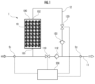
- FIG. 1 is a configuration explanatory diagram of a target liquid processing apparatus as an embodiment of the present invention.
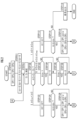
- FIG. 1 is a first functional explanatory diagram of a target liquid processing device as an embodiment of the present invention.
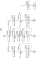
- FIG. 2 is a second functional explanatory diagram of a target liquid processing device as an embodiment of the present invention.
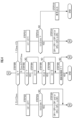
- FIG. 3 is a third functional explanatory diagram of a target liquid processing device as an embodiment of the present invention.
- the target liquid processing device as an embodiment of the present invention shown in FIG. It includes a second flow control valve 120, a first check valve 112, a second check valve 122, a first concentration sensor S1 , a second concentration sensor S2 , and a control device 200.
- the first flow path 11 is configured so that dialysis waste fluid, hemofiltrate, or hemodiafiltrate flowing out from a dialyzer or diafilter (not shown) flows (or circulates) as a target liquid.
- Dialyzers and the like are used in dialysis treatment for patients with chronic renal failure, acute renal failure, or patients requiring plasma exchange therapy.
- the target liquid processing device may be used to lower the potassium level of blood for transfusion or to adjust the ion balance.
- the second flow path 12 is configured to branch from the first flow path 11 and then merge with the first flow path 11 on the downstream side of the branch point.
- the target substance removal device 1 is provided in the second flow path 12 and has a function of selectively removing the target substance contained in the target liquid.
- the target substance removal device 1 includes a housing 100 and a plurality of ion adsorbents 10 filled or arranged in the internal space of the housing 100.
- the casing 100 has an inlet 101 that allows the target liquid flowing through the second flow path 12 to flow into the internal space, and an outflow port 102 that allows the dialysis waste fluid and the like to flow out from the internal space into the second flow path 12. are doing.
- the target substance removal device 1 is configured to be attachable to and detachable from the tubular member constituting the second flow path 12, and furthermore, to be replaceable.
- the ion adsorbent 10 may contain at least one of an ion exchange resin, a polymer gel, and a ceramic adsorbent.
- the ion adsorbent 10 may be composed of, for example, a base material made of a porous polymer and a large number of ion adsorbent fine particles dispersed in the base material. They may have the property of selectively adsorbing target substances such as potassium ions, ammonium ions, calcium ions, and/or magnesium ions and/or uremic toxins.
- the first flow control valve 110 is provided in the first flow path 11 between the branch point and the merge point of the second flow path 12.
- the second flow rate control valve 120 is provided downstream of the target substance removal device 1 in the second flow path 12 .
- the second flow rate control valve 120 may be provided upstream of the target substance removal device 1 in the second flow path 12 .
- the first check valve 112 is provided downstream of the first flow control valve 110 in the first flow path 11 .
- the second check valve 122 is provided downstream of the second flow control valve 120 in the second flow path 12 .
- the first check valve 112 and/or the second check valve 122 may be omitted.
- the first concentration sensor S 1 is located upstream of the confluence point of the second flow path 12 (further than the branch point in this embodiment) in the first flow path 11 and detects the concentration of the substance to be removed in the target liquid. It is configured to output a signal corresponding to one concentration C1 .
- the second concentration sensor S2 is configured to output a signal corresponding to a second concentration C2, which is the concentration of the substance to be removed in the target liquid, on the downstream side of the confluence point of the second flow path in the first flow path 11 . It is configured.
- the control device 200 includes a processor (arithmetic processing unit), memory (storage device) such as ROM and RAM, an I/F circuit, and the like.
- the arithmetic processing unit constituting the control device 200 reads necessary data and programs (software) from the storage device, and performs arithmetic processing on the data according to the program, thereby performing flow rate control processing, etc., which will be described later. perform tasks;
- the control device 200 is configured to adjust the opening degree of each of the first flow rate control valve 110 and the second flow rate control valve 120 based on the measurement results of the first concentration C 1 and the second concentration C 2 .
- the opening degree OP 1 of the first flow rate adjustment valve 110 is controlled to OP 10
- the opening degree of the second flow rate adjustment valve 120 is controlled to OP 10.
- OP 2 is controlled by OP 20 (FIG. 2/STEP 010).
- each of the difference indexes “i 01 ”, “i 02 ”, “i 11 ”, “i 12 ”, “i 21 ” and “i 22 ”, which will be described later, is reset to “0” ( Figure 2/STEP011 ).
- a first concentration C 1 that is the concentration of the substance to be removed in the target liquid is measured upstream of the branch point of the second flow path 12 in the first flow path 11 .
- a second concentration C2 which is the concentration of the substance to be removed in the target liquid, is determined on the downstream side of the confluence point of the second flow path 12 in the first flow path 11 . It is measured (FIG. 2/STEP012).
- the magnitude of the concentration difference ⁇ C represents the level of removal performance (or adsorption performance) of the target substance to be removed by the target liquid processing device.
- the flow rate Q1 of the target liquid flowing into the first flow path 11 and the flow rate Q2 of the target liquid flowing into the second flow path 12 are determined.
- the concentration change amount ⁇ C 0 is derived according to relational expression (01). Instead of the density difference ⁇ C, it may be determined whether the density change amount ⁇ C 0 is included in the designated density difference range. It is assumed that while the specific gravity G of the target liquid is the same, the differential pressure ⁇ p 1 upstream and downstream of the first flow rate regulating valve 110 and the differential pressure ⁇ p 2 upstream and downstream of the second flow rate regulating valve 120 are different.
- the first difference index i 01 is increased by "1" (FIG. 2/STEP 112) .
- the first difference index “i 01 ” is an index representing the duration of a situation in which the concentration difference ⁇ C is less than the lower limit value ⁇ C min of the designated concentration difference range.
- the increase width of the first difference index i 01 is adjusted to be larger as the rate of increase of the concentration difference ⁇ C (d ⁇ C/dt) is smaller (for example, "2" or "3", which is much greater than "1"). Good too.
- the opening degree OP 1 of the first flow rate control valve 110 is reduced by ⁇ OP 1 and/or the opening degree OP of the second flow rate control valve 120 is decreased.
- the operation of the first flow rate control valve 110 and/or the second flow rate control valve 120 is controlled such that 2 is increased by ⁇ OP 2 (FIG. 2/STEP 116).
- the flow rate of the target liquid in the second flow path 12 and, ultimately, in the target substance removal device 1 is increased.
- the processing after the connector X0 is executed. That is, the processing after the measurement processing of the first density C 1 and the second density C 2 (FIG. 2/STEP 012) is repeated.
- Adjustment is made such that the opening degree decreasing width ⁇ OP 1 of the first flow rate regulating valve 110 and/or the opening degree increasing width ⁇ OP 2 of the second flow rate regulating valve 120 becomes larger as the rate of increase of the concentration difference ⁇ C (d ⁇ C/dt) is smaller. may be done.
- the second difference index i 02 is increased by "1" (FIG. 2/STEP 122). ).
- the second difference index “i 02 ” is an index representing the duration of the situation in which the concentration difference ⁇ C exceeds the upper limit value ⁇ C max of the designated concentration difference range.
- the increase width of the second difference index i 02 is adjusted to be larger as the rate of decrease of the concentration difference ⁇ C (d ⁇ C/dt) is smaller (for example, "2" or "3", which is much larger than "1"). Good too.
- the opening degree OP 1 of the first flow rate adjustment valve 110 is increased by ⁇ OP 1 and/or the opening degree OP of the second flow rate adjustment valve 120 is increased.
- 2 is reduced by ⁇ OP 2
- the operation of the first flow rate control valve 110 and/or the second flow rate control valve 120 is controlled (FIG. 2/STEP 126).
- the flow rate of the target liquid in the second flow path 12 and, ultimately, in the target substance removal device 1 is reduced.
- the processes starting from the measurement process of the first density C 1 and the second density C 2 (FIG. 2/STEP 012) are repeated.
- the opening increase width ⁇ OP 1 of the first flow rate adjustment valve 110 and/or the opening decrease width ⁇ OP 2 of the second flow rate adjustment valve 120 are adjusted so that they become larger as the rate of decrease in concentration difference ⁇ C (d ⁇ C/dt) decreases. may be done.
- the first difference index i 01 is reset to "0" (FIG. 2/STEP 104), and the second difference index i 02 is set to 0. It is determined whether or not the limit is exceeded (FIG. 2/STEP 106). If the determination result is negative (FIG. 2/STEP 102...NO), it is determined whether the second difference index i 02 exceeds 0 (FIG. 2/STEP 106).
- the first upstream index i 11 is increased by "1" (FIG. 3/STEP 200...1). 3/STEP212).
- the first upstream index "i 11 " is an index representing the duration of the situation in which the first concentration C 1 exceeds the upper limit value C 1max of the first specified concentration range. The smaller the rate of decrease in the first concentration C 1 (dC 1 /dt) and/or the rate of decrease in the second concentration C 2 (dC 2 /dt), the smaller the increase width of the first upstream index i 11 (for example, “2 ” or “3”, etc., may be adjusted to be significantly larger than “1”). Subsequently, it is determined whether the first upstream index i 11 is less than or equal to the first upstream threshold i 11th (FIG. 3/STEP 214).
- the opening degree OP 1 of the first flow rate adjustment valve 110 is decreased by ⁇ OP 1 and/or the opening degree OP of the second flow rate adjustment valve 120 is decreased.
- 2 is increased by ⁇ OP 2
- the operation of the first flow rate control valve 110 and/or the second flow rate control valve 120 is controlled (FIG. 3/STEP 216).
- the flow rate of the target liquid in the second flow path 12 and, ultimately, in the target substance removal device 1 is increased.
- the processing after the connector X0 is executed. That is, the processing after the measurement processing of the first density C 1 and the second density C 2 (FIG. 2/STEP 012) is repeated.
- the first concentration C 1 is newly measured and then Process for determining whether the first concentration C 1 is included in the first specified concentration range [C 1min , C 1max ], is less than its lower limit C 1min , or exceeds its upper limit C 1max (Fig. 3/STEP200) may be executed.
- the opening degree reduction width ⁇ OP 1 of the first flow rate adjustment valve 110 and/or the opening degree increase width ⁇ OP 2 of the second flow rate adjustment valve 120 are determined by the rate of decrease in the first concentration C 1 (dC 1 /dt) and/or the opening degree increase width ⁇ OP 2 of the second flow rate adjustment valve 120.
- the second upstream index i 12 is increased by "1" (FIG. 3 /STEP222).
- the second upstream index "i 12 " is an index representing the duration of the situation in which the first concentration C 1 is less than the lower limit value C 1 min of the first designated concentration range.
- the opening degree OP 1 of the first flow rate adjustment valve 110 is increased by ⁇ OP 1 and/or the opening degree OP of the second flow rate adjustment valve 120 is increased.
- 2 is reduced by ⁇ OP 2
- the operation of the first flow rate control valve 110 and/or the second flow rate control valve 120 is controlled (FIG. 3/STEP 226). Thereby, the flow rate of the target liquid in the second flow path 12 and, ultimately, in the target substance removal device 4 is reduced. Thereafter, the processes starting from the measurement process of the first density C 1 and the second density C 2 (FIG. 2/STEP 012) are repeated.
- the opening degree OP 1 of the first flow rate control valve 110 is immediately changed to the maximum value.
- the first flow rate control valve 110 and the opening degree OP2 of the second flow rate control valve 120 are immediately decreased to the minimum value OP2min (for example , 0%).
- the operation of each of the second flow control valves 120 may be controlled.
- the first concentration C 1 is newly measured, and whether the first concentration C 1 is included in the first specified concentration range [C 1min , C 1max ] or its lower limit C 1 is determined.
- a process (FIG. 3/STEP 200) may be executed to determine whether it is less than 1 min or exceeds its upper limit value C 1max .
- the opening degree increase width ⁇ OP 1 of the first flow rate adjustment valve 110 and/or the opening degree decrease width ⁇ OP 2 of the second flow rate adjustment valve 120 are determined by the rate of increase in the first concentration C 1 (dC 1 /dt) and/or the opening degree decrease width ⁇ OP 2 of the second flow rate adjustment valve 120.
- the rate of increase in concentration C 2 (dC 2 /dt) may be adjusted to be larger as the rate of increase is smaller.
- the opening degree OP 1 of the first flow rate control valve 110 and the The opening degree OP2 of the second flow rate control valve 120 is maintained as it is.
- the first upstream index i 11 is reset to "0" (FIG. 3/STEP 204), and the second upstream index i 12 is set to 0. It is determined whether or not the limit is exceeded (FIG. 3/STEP 206). If the determination result is negative (FIG. 3/STEP 202...NO), it is determined whether the second upstream index i 12 exceeds 0 (FIG. 3/STEP 206).
- the first downstream index i 21 is increased by "1" (FIG. 4/STEP 300...1). 4/STEP312).
- the first downstream index "i 21 " is an index representing the duration of the situation in which the second concentration C 2 exceeds the upper limit value C 2max of the second specified concentration range.
- the increase width of the first downstream index i 21 becomes larger as the rate of decrease of the second concentration C 2 (dC 2 /dt) is smaller (for example, “2” or “3”, which is much greater than “1”). May be adjusted.
- the opening degree OP 1 of the first flow rate control valve 110 is decreased by ⁇ OP 1 and/or the opening degree OP of the second flow rate control valve 120 is decreased.
- 2 is increased by ⁇ OP 2
- the operation of the first flow rate control valve 110 and/or the second flow rate control valve 120 is controlled (FIG. 4/STEP 316).
- the flow rate of the target liquid in the second flow path 12 and, ultimately, in the target substance removal device 4 is increased.
- the processing after the connector X0 is executed. That is, the processing after the measurement processing of the first density C 1 and the second density C 2 (FIG. 2/STEP 012) is repeated.
- the lower opening degree ⁇ OP 1 of the first flow rate adjustment valve 110 and/or the opening degree increase width ⁇ OP 2 of the second flow rate adjustment valve 120 becomes larger as the rate of decrease in the second concentration C 2 (dC 2 /dt) is smaller. It may be adjusted as follows.
- the second downstream index i22 is increased by "1" (FIG. 4). /STEP322). This is an index representing the duration of a situation in which the second concentration C 2 is less than the lower limit value C 2 min of the second designated concentration range.
- the increase width of the second downstream index i 22 becomes larger as the rate of increase in the second concentration C 2 (dC 2 /dt) is smaller (for example, “2” or “3”, which is much greater than “1”). May be adjusted.
- the opening degree OP 1 of the first flow rate adjustment valve 110 is increased by ⁇ OP 1 and/or the opening degree OP of the second flow rate adjustment valve 120 is increased.
- 2 is reduced by ⁇ OP 2
- the operation of the first flow rate control valve 110 and/or the second flow rate control valve 120 is controlled (FIG. 4/STEP 326).
- the flow rate of the target liquid in the second flow path 12 and, ultimately, in the target substance removal device 4 is reduced.
- the processes starting from the measurement process of the first density C 1 and the second density C 2 (FIG. 2/STEP 012) are repeated.
- the opening degree OP 1 of the first flow rate control valve 110 is immediately changed to the maximum value.
- the first flow rate control valve 110 and the opening degree OP2 of the second flow rate control valve 120 are immediately decreased to the minimum value OP2min (for example , 0%).
- the operation of each of the second flow control valves 120 may be controlled.
- the second concentration C 2 is newly measured, and it is determined whether the second concentration C 2 is included in the second specified concentration range [C 2min , C 2max ] or its lower limit C 2 .
- a determination process (FIG.
- 4/STEP 300 may be performed to determine whether it is less than 2 min or exceeds its upper limit C 2 max . Then, if it is determined that the second concentration C 2 is included in the second specified concentration range [C 2min , C 2max ] (FIG. 4/STEP 300...0), the process is immediately performed without executing any intermediate processing. Processing after connector X0 may be executed.
- the opening increase width ⁇ OP 1 of the first flow rate adjustment valve 110 and/or the opening decrease width ⁇ OP 2 of the second flow rate adjustment valve 120 increases as the rate of increase in the second concentration C 2 (dC 2 /dt) decreases. It may be adjusted as follows.
- the opening degree OP 1 of the first flow rate control valve 110 and the second concentration range [C 1min , C 1max ] are determined.
- the opening degree OP2 of the second flow rate control valve 120 is maintained as it is.
- the first downstream index i 21 is reset to "0" (FIG. 4/STEP 304), and the second downstream index i 22 is set to 0. It is determined whether it exceeds the limit (FIG. 4/STEP 306). If the determination result is negative (FIG. 4/STEP 302...NO), it is determined whether the second downstream index i 22 exceeds 0 (FIG. 4/STEP 306).
- the second downstream index i 22 is reset to "0" (FIG. 4/STEP 308), and then whether or not the end condition is satisfied is determined. is determined (FIG. 4/STEP 309). If the determination result is negative (FIG. 4/STEP 306...NO), it is determined whether the termination condition is satisfied (FIG. 4/STEP 309).
- Termination conditions include, for example, the condition that the operation of the target liquid processing device is instructed to stop by turning the operation switch OFF, etc., and/or the condition that the continuous operation time of the target liquid processing device exceeds a predetermined time, etc. It is included. If it is determined that the termination condition is not satisfied (FIG. 4/STEP 309...NO), the processing after connector X0 is executed. That is, the processing after the measurement processing of the first density C 1 and the second density C 2 (FIG. 2/STEP 012) is repeated. On the other hand, if it is determined that the end condition is satisfied (FIG. 4/STEP 309...YES), the series of processes ends.
- the control device 200 removes the target substance for removal using the target substance removal device 1 in the target liquid based on the measurement results of the first concentration C 1 and the second concentration C 2 From this point of view, the opening degree OP 1 of the first flow rate adjustment valve 110 and/or the opening degree OP 2 of the second flow rate adjustment valve 120 is adjusted appropriately.
- the concentration difference ⁇ C is included in the specified concentration difference range [ ⁇ C min , ⁇ C max ], is less than its lower limit ⁇ C min , or exceeds its upper limit ⁇ C max .
- the first concentration C 1 is included in the first designated concentration range [C 1min , C 1max ], is less than its lower limit C 1min , or exceeds its upper limit C 1max .
- the first concentration threshold for example, a value corresponding to C 1 min ). It's okay.
- the processes of FIG. 3/STEP 206 ⁇ STEP 208 ⁇ STEP 212 ⁇ STEP 216 and STEP 218 are executed. If it is determined that the first concentration C 1 is less than or equal to the first concentration threshold, the process of FIG. 3 / STEP 202 ⁇ STEP 204 ⁇ STEP 222 ⁇ STEP 226 is executed, and the connector X0 following FIG. 3 / STEP 226 becomes the connector X2. May be replaced.
- the second concentration C 2 is included in the second specified concentration range [C 2min , C 2max ], is less than its lower limit C 2min , or exceeds its upper limit C 2max .
- the second concentration threshold for example, a value corresponding to C 2 min . It's okay.
- the processing of STEP 306 ⁇ STEP 308 ⁇ STEP 312 ⁇ STEP 316 and STEP 318 in FIG. 4 is executed. If it is determined that the second density C 2 is less than or equal to the second density threshold, the processing in FIG. 4 from STEP 302 ⁇ STEP 304 ⁇ STEP 322 ⁇ STEP 326 is executed.
- the processing after connector X1 (the processing after FIG. 3/STEP 200) is executed, and further the processing after connector X2 (the processing after FIG. ) was performed; however, in other embodiments, the order of the three processes may be swapped, only a single process among the three processes may be performed, or The two processes may be performed in any order.
- the adjustment width ⁇ OP 1 of the opening degree OP 1 of the first flow rate control valve 110 in each of FIG. 2 / STEP 116 and STEP 126, FIG. 3 / STEP 216 and STEP 226, and FIG. 4 / STEP 316 and STEP 326 may be the same (for example, , the increase width ⁇ OP 1 is smaller than the decrease width ⁇ OP 1 , etc.) may be different from each other.
- the adjustment width ⁇ OP 2 of the opening degree OP 2 of the second flow rate control valve 120 in each of FIG. 2 / STEP 116 and STEP 126, FIG. 3 / STEP 216 and STEP 226, and FIG. 4 / STEP 316 and STEP 326 is the same They may be different from each other (for example, the increase width ⁇ OP 2 is larger than the decrease width ⁇ OP 2 ).
- Target substance removal device 10. Ion adsorbent 11. First channel 12. Second channel 100. Housing 101. Inflow port 102. Outlet port 110. First flow rate adjustment valve 112. First check valve 120. ...Second flow control valve 122 ...Second check valve 200 ...Control device S1 ...First concentration sensor S2 ...Second concentration sensor.
Landscapes
- Health & Medical Sciences (AREA)
- Heart & Thoracic Surgery (AREA)
- Urology & Nephrology (AREA)
- Anesthesiology (AREA)
- Vascular Medicine (AREA)
- Engineering & Computer Science (AREA)
- Biomedical Technology (AREA)
- Hematology (AREA)
- Life Sciences & Earth Sciences (AREA)
- Animal Behavior & Ethology (AREA)
- General Health & Medical Sciences (AREA)
- Public Health (AREA)
- Veterinary Medicine (AREA)
- Emergency Medicine (AREA)
- External Artificial Organs (AREA)
Priority Applications (2)
| Application Number | Priority Date | Filing Date | Title |
|---|---|---|---|
| US18/878,319 US20260137850A1 (en) | 2022-08-23 | 2023-08-18 | Target liquid treatment apparatus |
| JP2024542799A JPWO2024043193A1 (cg-RX-API-DMAC7.html) | 2022-08-23 | 2023-08-18 |
Applications Claiming Priority (2)
| Application Number | Priority Date | Filing Date | Title |
|---|---|---|---|
| JP2022-132837 | 2022-08-23 | ||
| JP2022132837 | 2022-08-23 |
Publications (1)
| Publication Number | Publication Date |
|---|---|
| WO2024043193A1 true WO2024043193A1 (ja) | 2024-02-29 |
Family
ID=90013312
Family Applications (1)
| Application Number | Title | Priority Date | Filing Date |
|---|---|---|---|
| PCT/JP2023/029885 Ceased WO2024043193A1 (ja) | 2022-08-23 | 2023-08-18 | 対象液処理装置 |
Country Status (4)
| Country | Link |
|---|---|
| US (1) | US20260137850A1 (cg-RX-API-DMAC7.html) |
| JP (1) | JPWO2024043193A1 (cg-RX-API-DMAC7.html) |
| TW (1) | TW202417063A (cg-RX-API-DMAC7.html) |
| WO (1) | WO2024043193A1 (cg-RX-API-DMAC7.html) |
Citations (6)
| Publication number | Priority date | Publication date | Assignee | Title |
|---|---|---|---|---|
| JP2008502449A (ja) * | 2004-06-09 | 2008-01-31 | リナル・ソリューションズ・インコーポレーテッド | 透析システム |
| JP2011505209A (ja) * | 2007-12-03 | 2011-02-24 | ヘパ ウォッシュ ゲゼルシャフト ミット ベシュレンクテル ハフツング | 透析液再生ユニット |
| JP2014525804A (ja) * | 2011-08-02 | 2014-10-02 | メドトロニック,インコーポレイテッド | 制御された追従的な容積を有する流路を有する血液透析システム |
| JP2018047167A (ja) * | 2016-09-23 | 2018-03-29 | 日機装株式会社 | 血液浄化装置 |
| JP2019509121A (ja) * | 2016-03-14 | 2019-04-04 | ヘパ ウォッシュ ゲゼルシャフト ミット ベシュレンクテル ハフツング | 透析を行うためのシステム又は装置及び方法 |
| JP2021515634A (ja) * | 2018-03-06 | 2021-06-24 | フレゼニウス メディカル ケア ドイッチェランド ゲゼルシャフト ミット ベシュレンクテル ハフツング | 透析液を再生するのための装置及び方法 |
-
2023
- 2023-08-18 JP JP2024542799A patent/JPWO2024043193A1/ja active Pending
- 2023-08-18 WO PCT/JP2023/029885 patent/WO2024043193A1/ja not_active Ceased
- 2023-08-18 US US18/878,319 patent/US20260137850A1/en active Pending
- 2023-08-23 TW TW112131628A patent/TW202417063A/zh unknown
Patent Citations (6)
| Publication number | Priority date | Publication date | Assignee | Title |
|---|---|---|---|---|
| JP2008502449A (ja) * | 2004-06-09 | 2008-01-31 | リナル・ソリューションズ・インコーポレーテッド | 透析システム |
| JP2011505209A (ja) * | 2007-12-03 | 2011-02-24 | ヘパ ウォッシュ ゲゼルシャフト ミット ベシュレンクテル ハフツング | 透析液再生ユニット |
| JP2014525804A (ja) * | 2011-08-02 | 2014-10-02 | メドトロニック,インコーポレイテッド | 制御された追従的な容積を有する流路を有する血液透析システム |
| JP2019509121A (ja) * | 2016-03-14 | 2019-04-04 | ヘパ ウォッシュ ゲゼルシャフト ミット ベシュレンクテル ハフツング | 透析を行うためのシステム又は装置及び方法 |
| JP2018047167A (ja) * | 2016-09-23 | 2018-03-29 | 日機装株式会社 | 血液浄化装置 |
| JP2021515634A (ja) * | 2018-03-06 | 2021-06-24 | フレゼニウス メディカル ケア ドイッチェランド ゲゼルシャフト ミット ベシュレンクテル ハフツング | 透析液を再生するのための装置及び方法 |
Also Published As
| Publication number | Publication date |
|---|---|
| US20260137850A1 (en) | 2026-05-21 |
| TW202417063A (zh) | 2024-05-01 |
| JPWO2024043193A1 (cg-RX-API-DMAC7.html) | 2024-02-29 |
Similar Documents
| Publication | Publication Date | Title |
|---|---|---|
| EP1424089B1 (en) | Dialysis machine | |
| CN101516416B (zh) | 用于确定体外血液处理的透析流体流动速率或血液流动速率的设备和方法 | |
| US5685988A (en) | Dialysis process and system | |
| CN101184517B (zh) | 用于在crrt中优化血液过滤回路中柠檬酸盐抗凝剂补给的系统 | |
| CN103717132B (zh) | 液体清除治疗的电解质和pH值的监测 | |
| JP2017176847A5 (cg-RX-API-DMAC7.html) | ||
| EP2253342B1 (de) | Vorrichtung zur extrakorporalen Blutbehandlung | |
| EP2467178B1 (de) | Schlauchset für eine vorrichtung zur blutbehandlung und vorrichtung zur blutbehandlung mit einem schlauchset | |
| JP2000000300A (ja) | 血液処理装置のための安全装置および血液処理装置の安全性を高めるための方法 | |
| KR19980024552A (ko) | 혈액 처리 방법 및 그 장치 | |
| JP2012504481A (ja) | 体外での血液処理のための装置及び前記装置を管理する方法 | |
| JP2020124526A5 (cg-RX-API-DMAC7.html) | ||
| CN102215886B (zh) | 血浆净化装置 | |
| JP2012526569A (ja) | 体外血液処理を最適化するための方法および装置 | |
| JP7805514B1 (ja) | 血液浄化装置、情報処理装置、除水プロファイルの設定方法、及び処理プログラム | |
| TW202417063A (zh) | 對象液處理裝置 | |
| CA2574529C (en) | Dialysis machine with arterial pressure monitoring by measuring oxygen saturation | |
| KR20230066319A (ko) | 투석용 필터 디바이스 | |
| JP6785365B2 (ja) | 血液浄化装置及びその制御方法 | |
| WO2011074603A1 (ja) | 血液透析装置 | |
| JP7514899B2 (ja) | 心肺バイパスから残留血液を回収する方法、及び心肺バイパスから残留血液を収集し回収する機器 | |
| JP7484933B2 (ja) | 血液浄化装置 | |
| CN111068134A (zh) | 一种无透析液的血液净化器 | |
| JP2006043315A (ja) | 血液濾過装置 | |
| JPS607725Y2 (ja) | 人工腎臓透析液の脱気装置 |
Legal Events
| Date | Code | Title | Description |
|---|---|---|---|
| 121 | Ep: the epo has been informed by wipo that ep was designated in this application |
Ref document number: 23857304 Country of ref document: EP Kind code of ref document: A1 |
|
| WWE | Wipo information: entry into national phase |
Ref document number: 2024542799 Country of ref document: JP |
|
| WWE | Wipo information: entry into national phase |
Ref document number: 18878319 Country of ref document: US |
|
| NENP | Non-entry into the national phase |
Ref country code: DE |
|
| 122 | Ep: pct application non-entry in european phase |
Ref document number: 23857304 Country of ref document: EP Kind code of ref document: A1 |
|
| WWP | Wipo information: published in national office |
Ref document number: 18878319 Country of ref document: US |