WO2024042947A1 - Partie bobine - Google Patents
Partie bobine Download PDFInfo
- Publication number
- WO2024042947A1 WO2024042947A1 PCT/JP2023/026907 JP2023026907W WO2024042947A1 WO 2024042947 A1 WO2024042947 A1 WO 2024042947A1 JP 2023026907 W JP2023026907 W JP 2023026907W WO 2024042947 A1 WO2024042947 A1 WO 2024042947A1
- Authority
- WO
- WIPO (PCT)
- Prior art keywords
- facing
- mounting surface
- mounting
- surface facing
- outer end
- Prior art date
Links
- 239000002184 metal Substances 0.000 claims abstract description 151
- 229910052751 metal Inorganic materials 0.000 claims abstract description 151
- 238000004804 winding Methods 0.000 claims abstract description 27
- 230000000630 rising effect Effects 0.000 claims description 31
- 230000001105 regulatory effect Effects 0.000 claims description 21
- 230000002093 peripheral effect Effects 0.000 claims description 4
- 239000000853 adhesive Substances 0.000 description 17
- 230000001070 adhesive effect Effects 0.000 description 17
- 230000000694 effects Effects 0.000 description 6
- 239000000696 magnetic material Substances 0.000 description 5
- 238000000034 method Methods 0.000 description 5
- 229920005989 resin Polymers 0.000 description 5
- 239000011347 resin Substances 0.000 description 5
- 229910000679 solder Inorganic materials 0.000 description 5
- 229910000859 α-Fe Inorganic materials 0.000 description 4
- 230000008859 change Effects 0.000 description 3
- 239000011248 coating agent Substances 0.000 description 3
- 238000000576 coating method Methods 0.000 description 3
- VYPSYNLAJGMNEJ-UHFFFAOYSA-N Silicium dioxide Chemical compound O=[Si]=O VYPSYNLAJGMNEJ-UHFFFAOYSA-N 0.000 description 2
- PNEYBMLMFCGWSK-UHFFFAOYSA-N aluminium oxide Inorganic materials [O-2].[O-2].[O-2].[Al+3].[Al+3] PNEYBMLMFCGWSK-UHFFFAOYSA-N 0.000 description 2
- 238000005452 bending Methods 0.000 description 2
- 239000006247 magnetic powder Substances 0.000 description 2
- 239000000463 material Substances 0.000 description 2
- 230000004048 modification Effects 0.000 description 2
- 238000012986 modification Methods 0.000 description 2
- 238000007747 plating Methods 0.000 description 2
- 239000000843 powder Substances 0.000 description 2
- 229910000906 Bronze Inorganic materials 0.000 description 1
- RYGMFSIKBFXOCR-UHFFFAOYSA-N Copper Chemical compound [Cu] RYGMFSIKBFXOCR-UHFFFAOYSA-N 0.000 description 1
- OAICVXFJPJFONN-UHFFFAOYSA-N Phosphorus Chemical compound [P] OAICVXFJPJFONN-UHFFFAOYSA-N 0.000 description 1
- 239000004962 Polyamide-imide Substances 0.000 description 1
- BQCADISMDOOEFD-UHFFFAOYSA-N Silver Chemical compound [Ag] BQCADISMDOOEFD-UHFFFAOYSA-N 0.000 description 1
- 230000001154 acute effect Effects 0.000 description 1
- 230000008901 benefit Effects 0.000 description 1
- 239000010974 bronze Substances 0.000 description 1
- 239000004020 conductor Substances 0.000 description 1
- 229910052802 copper Inorganic materials 0.000 description 1
- 239000010949 copper Substances 0.000 description 1
- KUNSUQLRTQLHQQ-UHFFFAOYSA-N copper tin Chemical compound [Cu].[Sn] KUNSUQLRTQLHQQ-UHFFFAOYSA-N 0.000 description 1
- 238000010586 diagram Methods 0.000 description 1
- 238000005516 engineering process Methods 0.000 description 1
- 239000003822 epoxy resin Substances 0.000 description 1
- 239000000945 filler Substances 0.000 description 1
- PCHJSUWPFVWCPO-UHFFFAOYSA-N gold Chemical compound [Au] PCHJSUWPFVWCPO-UHFFFAOYSA-N 0.000 description 1
- 229910052737 gold Inorganic materials 0.000 description 1
- 239000010931 gold Substances 0.000 description 1
- 239000011256 inorganic filler Substances 0.000 description 1
- 229910003475 inorganic filler Inorganic materials 0.000 description 1
- 230000007774 longterm Effects 0.000 description 1
- 238000004519 manufacturing process Methods 0.000 description 1
- 229920003055 poly(ester-imide) Polymers 0.000 description 1
- 229920002312 polyamide-imide Polymers 0.000 description 1
- 229920000647 polyepoxide Polymers 0.000 description 1
- 239000004814 polyurethane Substances 0.000 description 1
- 229920002635 polyurethane Polymers 0.000 description 1
- 238000007639 printing Methods 0.000 description 1
- 230000004044 response Effects 0.000 description 1
- 230000035939 shock Effects 0.000 description 1
- 239000000377 silicon dioxide Substances 0.000 description 1
- 229910052709 silver Inorganic materials 0.000 description 1
- 239000004332 silver Substances 0.000 description 1
- 238000006467 substitution reaction Methods 0.000 description 1
- 230000002459 sustained effect Effects 0.000 description 1
- 229920001187 thermosetting polymer Polymers 0.000 description 1
Images


Classifications
-
- H—ELECTRICITY
- H01—ELECTRIC ELEMENTS
- H01F—MAGNETS; INDUCTANCES; TRANSFORMERS; SELECTION OF MATERIALS FOR THEIR MAGNETIC PROPERTIES
- H01F27/00—Details of transformers or inductances, in general
- H01F27/28—Coils; Windings; Conductive connections
- H01F27/29—Terminals; Tapping arrangements for signal inductances
Definitions
- the present invention relates to a wire-wound coil component having a structure in which a wire is wound around a core, and particularly to a structure for attaching a metal terminal made of a metal plate to the core.
- Patent Document 1 Japanese Patent Application Publication No. 2006-4989 (Patent Document 1) describes a wire-wound coil component having a structure in which a wire is wound around a core. More specifically, the core has a winding core extending in the axial direction and a pair of flanges provided at opposite ends of the winding core in the axial direction. A metal terminal made of a metal plate is attached to each collar. A wire is wound around the winding core, and the wire is connected to a metal terminal.
- the flange connects the mounting surface facing the mounting board side, the top surface facing the opposite side of the mounting surface, and the mounting surface and the top surface during mounting. It has an inner end surface on which the end of the core portion in the axial direction is located, and an outer end surface facing opposite to the inner end surface.
- the metal terminal has a mounting surface facing portion, an outer end surface facing portion, and a top surface facing portion that respectively face the mounting surface, the outer end surface, and the top surface of the flange, and is connected to It continues to the outer end face facing part, and from the outer end face facing part to the top face facing part via the bending part.
- At least one of the angle between the outer end surface and the mounting surface of the flange and the angle between the outer end surface and the top surface is an acute angle, so that the mounting surface facing part and the top surface are opposite to each other.
- the flange is sandwiched between the metal terminal and the flange, making it difficult for the metal terminal to come off from the flange.
- Patent Document 1 a concave portion with a circular opening is provided on the mounting surface and the top surface of the flange, and a convex portion with a spherical surface is provided on the mounting surface facing portion and the top surface facing portion of the metal terminal.
- the two directions are positive and negative with respect to the axial direction of the winding core (hereinafter also referred to as the "L direction”), and the direction perpendicular to the L direction, and the direction connecting the mounting surface and the top surface (hereinafter referred to as the "T direction”). ), and the direction in which the mounting surface and the top surface extend (hereinafter also referred to as the "W direction”). Therefore, in order to prevent the metal terminal from coming off the collar, it is necessary to withstand external forces in these six directions. Note that an external force directed from the mounting surface toward the top surface in the T direction does not normally occur when the coil component is mounted on the mounting board, but it can occur instantaneously due to impact when dropped, etc. There is sex.
- each of the pair of metal terminals has a mounting surface facing portion, an outer end surface facing portion, and a top surface facing portion, so that it can be used in two directions, positive and negative in the T direction and in the L direction. It is considered that the external force in four directions (positive and negative directions) can be sufficiently withstood because the specific surface of the metal terminal and the specific surface of the flange come into contact with each other.
- Patent Document 1 a recess with a circular opening is provided in the mounting surface and the top surface of the collar, and a spherical recess is provided in the mounting surface facing part and the top surface facing part of the metal terminal. It is described that a convex portion is provided. However, the resistance to external force due to the convex portion fitting into the concave portion is relatively weak, and it is considered that the above-mentioned external force in the rotational direction cannot be sufficiently coped with.
- an object of the present invention is to provide a coil component having a structure that can withstand external force in the rotational direction more than the technology described in Patent Document 1.
- the present invention includes a core having a winding core extending in the axial direction and a pair of flanges provided at mutually opposite ends of the winding core in the axial direction, and a metal core attached to each of the flanges.
- the present invention is directed to a coil component comprising at least one pair of metal terminals each made of a plate, and at least one wire connected to each of the at least one pair of metal terminals and wound around a winding core.
- Each flange connects the mounting surface facing the mounting board side, the top surface facing the opposite side of the mounting surface, and the mounting surface and the top surface during mounting. an inner end surface on which an end in the axial direction of the winding core is located, an outer end surface facing opposite to the inner end surface, and a first side surface and a second side surface that connect the inner end surface and the outer end surface and face in opposite directions. and has.
- each metal terminal has a mounting surface facing portion facing the mounting surface, an outer end surface facing portion facing the outer end surface, and at least one of the first side surface and the second side surface. It has a side facing portion facing one side.
- the metal terminal includes a first regulating part for regulating movement of at least the outer end face facing part in a direction away from the outer end face (one direction in the L direction) with respect to the flange part, and at least a mounting face facing part.
- the present invention is characterized in that it further includes a second restriction portion for restricting movement in a direction away from the mounting surface (one direction in the T direction).
- a first regulating portion for regulating movement of at least the outer end surface facing portion in a direction away from the outer end surface (L direction), and a direction in which at least the mounting surface opposing portion moves away from the mounting surface (T direction). Since it is provided with both second regulating parts for regulating movement in the direction, it can not only resist external forces in the L direction and the T direction, but also resist external forces that cause rotation around an axis extending in the W direction.
- the metal terminal can be made difficult to come off from the flange. This is because the external force that causes rotation around the axis extending in the W direction can be considered as a combination of the external force in the L direction and the external force in the T direction.
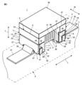
- FIG. 1 is a perspective view showing the appearance of a coil component 1 according to a first embodiment of the present invention, with mounting surfaces 7 and 8 facing upward.
- FIG. 2 is a perspective view showing a mounted state of the coil component 1 shown in FIG. 1.
- FIG. 3 is a perspective view for explaining a typical external force exerted on the coil component 1 in the mounted state shown in FIG. 2.
- FIG. 3 is a perspective view for explaining an external force in the rotational direction that is applied to the coil component 1 in the mounted state shown in FIG. 2.
- FIG. FIG. 7 is a perspective view showing the appearance of a coil component 1a according to a second embodiment of the present invention, with mounting surfaces 7 and 8 facing upward.
- FIG. 7 is a perspective view showing the appearance of a coil component 1b according to a third embodiment of the present invention, with mounting surfaces 7 and 8 facing upward.
- FIG. 7 is a perspective view showing the appearance of a coil component 1c according to a fourth embodiment of the present invention, with mounting surfaces 7 and 8 facing upward.
- FIG. 7 is a perspective view showing the appearance of a coil component 1d according to a fifth embodiment of the present invention, with mounting surfaces 7 and 8 facing upward.
- a coil component 1 according to a first embodiment of the present invention will be described with reference to FIGS. 1 to 4.
- the coil component 1 includes a winding core 2 extending in the axial direction (L direction), and a pair of flanges provided at mutually opposite ends of the winding core 2 in the L direction, that is, first flanges. 3 and a second flange 4, the drum-shaped core 5 is provided.
- the core 5 is made of a magnetic material such as ferrite, a resin containing ferrite powder or metal magnetic powder, or a non-magnetic material such as alumina.
- the winding core 2 has a substantially rectangular cross-sectional shape in the drawings, it may also have a polygonal shape such as a hexagonal shape, a circular shape, an elliptical shape, or a combination thereof.
- the first flange 3 connects a mounting surface 7 that faces the mounting board 6 (see FIG. 2) side during mounting, a top surface 9 that faces the opposite side of the mounting surface 7, and the mounting surface 7 and the top surface 9.
- the inner end surface 11 faces the winding core 2 side and positions the end of the winding core 2 in the L direction
- the outer end surface 13 faces the opposite side of the inner end surface 11, and the inner end surface 11. It has a first side surface 15 and a second side surface 17 that connect the outer end surface 13 and face in opposite directions.
- the second flange 4 connects the mounting surface 8 facing the mounting board 6 side, the top surface 10 facing the opposite side of the mounting surface 8, and the mounting surface 8 and the top surface 10 during mounting.
- the dimensions of the core 5 are not limited, but as an example, the dimension in the L direction is 3.2 mm, which is a direction perpendicular to the L direction and in the direction in which the mounting surfaces 7 and 8 and the top surfaces 9 and 10 extend.
- the dimension in the direction (W direction) is 2.5 mm
- the dimension in the direction (T direction) connecting the mounting surfaces 7 and 8 and the top surfaces 9 and 10 is 1.8 mm.
- the coil component 1 constitutes a wire-wound inductor, for example, and includes a wire 21 wound around the winding core portion 2 of the core 5.
- the wire 21 includes, for example, a center wire made of a highly conductive metal such as copper, silver, or gold, and an insulating coating made of an electrically insulating resin such as polyamideimide, polyurethane, or polyesterimide that covers the center wire.
- the diameter of the center wire of the wire 21 does not matter, it is preferable to use one having a diameter of 80 ⁇ m or more and 200 ⁇ m or less, for example.
- the number of turns of the wire 21 on the winding core 2 does not matter.
- a pair of metal terminals 23 and 24 are attached to the flanges 3 and 4. More specifically, the first metal terminal 23 is attached to the first flange 3 , and the second metal terminal 24 is attached to the second flange 4 .
- the mutually opposite first and second ends of the wire 21 described above are connected to the first metal terminal 23 and the second metal terminal 24, respectively.
- the first metal terminal 23 and the second metal terminal 24 are each made of a single metal plate, and have substantially the same shape or a point-symmetrical shape.
- the metal plates constituting the metal terminals 23 and 24 for example, a plate formed by Ni plating and Sn plating on a base material made of phosphor bronze is used.
- the first metal terminal 23 includes a mounting surface facing portion 25, an outer end surface facing portion 27, and a first side surface facing portion 25 facing the mounting surface 7, the outer end surface 13, the first side surface 15, and the second side surface 17 of the first collar portion 3, respectively. portion 29 and a second side facing portion 31 .
- the second metal terminal 24 includes a mounting surface facing portion 26, an outer end surface facing portion 28, and a first side surface facing portion 26 facing the mounting surface 8, the outer end surface 14, the first side surface 16, and the second side surface 18 of the second collar portion 4, respectively. portion 30 and a second side facing portion 32 .
- the outer end surface facing portion 27 is continuous from the mounting surface facing portion 25 via the first bent portion 33, and the first side surface facing portion 29 and the second side surface facing portion 31 are It continues from the mounting surface facing portion 25 via the second bent portion 35 .
- the outer end face facing part 28 is continuous from the mounting surface facing part 26 via the first bent part 34, and the first side facing part 30 and the second side facing part 32 are connected to the mounting surface facing part 26. It continues from the opposing portion 26 via the second bent portion 36 .
- the first end and the second end of the wire 21 are connected to the mounting surface facing portion 25 of the first metal terminal 23 and the mounting surface facing portion 26 of the second metal terminal 24, respectively, by thermocompression bonding, for example. .
- the coil component 1 is mounted with metal terminals 23 and 24 connected to conductive lands 37 and 38 provided on the mounting board 6 via solder.
- FIG. 2 shows a fillet 39 formed by solder that connects the conductive land 37 and the first metal terminal 23. As shown in FIG.
- a top plate 40 is provided on the coil component 1 so as to connect the top surface 9 of the first flange 3 of the core 5 and the top surface 10 of the second flange 4.
- the top plate 40 is bonded to the core 5 with an adhesive.
- the adhesive for example, a thermosetting epoxy resin is used.
- Inorganic fillers such as silica fillers may be added to the adhesive to improve its thermal shock resistance.
- Examples of adhesive application methods include a printing method in which the adhesive is applied to the top plate 40, a method in which the top surfaces 9 and 10 sides of the flanges 3 and 4 of the core 5 are dipped in adhesive, and a method in which the adhesive is applied to the top plate 40 and the core 5.
- a method such as dispensing adhesive on both sides can be adopted.
- the material for the top plate 40 for example, a magnetic material such as ferrite, a resin containing ferrite powder or metal magnetic powder, or a non-magnetic material such as alumina is used.
- a resin coating may be applied. Note that the top plate 40 and the resin coating may not be provided.
- the first flange portion 3 resists the external force in the direction from the top surfaces 9 and 10 toward the mounting surfaces 7 and 8 in the T direction.
- the resistance can be maintained by the contact between the mounting surface 7 and the mounting surface facing portion 25 of the first metal terminal 23 and the contact between the mounting surface 8 of the second collar portion 4 and the mounting surface facing portion 26 of the second metal terminal 24. can.
- the metal terminals 23 and 24 can withstand external forces in at least the five directions described above without coming off from the flanges 3 and 4.
- This embodiment has a structure that makes it even more difficult for the metal terminals 23 and 24 to come off from the flanges 3 and 4. That is, the metal terminals 23 and 24 further include a regulating part for regulating the movement of at least the mounting surface facing parts 25 and 26 in a direction away from the mounting surfaces 7 and 8 with respect to the collar parts 3 and 4.
- the external forces directed from the mounting surfaces 7 and 8 toward the top surfaces 9 and 10 in the T direction are normally applied when the coil component 1 is mounted on the mounting board. Although this does not occur, it may occur instantaneously due to the impact of a fall, etc.
- the above-mentioned regulating portion is effective against external forces acting on the core 5 from the mounting surfaces 7 and 8 toward the top surfaces 9 and 10 in the T direction.
- the regulating portion includes a first convex portion 41 provided on at least one of the first side surface 15 and the second side surface 17 of the first collar portion 3, and the first metal terminal 23.
- a notch 42 is located on at least one of the first side facing portion 29 and the second side facing portion 31 of the terminal 23 and receives the first convex portion 41.
- the regulating portion includes the first convex portion 43 provided on at least one of the first side surface 16 and the second side surface 18 of the second collar portion 4 and the first convex portion 43 of the second metal terminal 24 .
- a notch 44 is located on at least one of the side facing portion 30 and the second side facing portion 32 and receives the first convex portion 43.
- the first metal terminal 23 receives a relatively large external force.
- a large area can be secured for the outer end surface facing portion 27 and the mounting surface facing portion 25 of the metal terminal 23.
- the same can be said of the notch portion 44 in the second metal terminal 24. Therefore, the effect of making it difficult for the metal terminals 23 and 24 to come off from the flanges 3 and 4 can be further enhanced.
- the first convex portion 41 is provided on both the first side surface 15 and the second side surface 17 of the first collar portion 3, and the notch portion 42 is provided on the first metal terminal 23. It is located on both the first side facing portion 29 and the second side facing portion 31 of 23.
- the second metal terminal 24 the first convex portion 43 is provided on both the first side surface 16 and the second side surface 18 of the second collar portion 4
- the notch portion 44 is provided on the first side surface 16 and the second side surface 18 of the second collar portion 4 . It is located on both the first side facing portion 30 and the second side facing portion 32.
- the first convex portion 41 is provided on both the first side surface 15 and the second side surface 17 of the first collar portion 3, and the first convex portion 43 is provided on both the first side surface 16 and the second side surface of the second collar portion 4.
- the metal terminals 23 and 24 are difficult to come off from the flanges 3 and 4, and the effect can be further enhanced.
- the mounting surface facing portions 25 and 26 not only move in the direction away from the mounting surfaces 7 and 8, but also in the outer end surface. Movement of the opposing parts 27 and 28 in the direction away from the outer end surfaces 13 and 14 can also be restricted.
- the first convex portion 41 has a first rising wall 45 extending along the direction in which the top surface 9 of the first collar portion 3 and the mounting surface 7 face each other, and the outer end surface 13 and a second rising wall 46 extending along the direction in which the inner end surface 11 and the inner end surface 11 face each other, and the cutout portion 42 faces the first opposing wall 47 that faces the first rising wall 45 and the second rising wall 46.
- a second opposing wall 48 is provided.
- the first convex portion 43 has a first rising wall 49 extending along the direction in which the top surface 10 of the second collar portion 4 and the mounting surface 8 face each other, and the outer end surface 14 and the inner end surface. 12 and a second rising wall 50 extending along the opposite direction, the cutout portion 44 provides a first opposing wall 51 facing the first rising wall 49 and a second opposing wall 50 facing the second rising wall 50.
- a wall 52 is provided.
- the contact between the first rising walls 45 and 49 and the first opposing walls 47 and 51 is such that the metal terminals 23 and 24 are in contact with the collar parts 3 and 4, and at least the outer end face facing parts 27 and 28 are in contact with the outer side. Although movement in the direction away from the end faces 13 and 14 is restricted, this state of contact does not necessarily need to be maintained when no external force is applied.
- the first rising walls 45 and 49 extend linearly in parallel with the inner end surfaces 11 and 12, respectively, and the second rising walls Preferably, 46 and 50 extend linearly parallel to mounting surfaces 7 and 8, respectively.
- the first convex portion 41 is connected to the outer end surface 13 and the mounting surface at the first side surface 15 and the second side surface 17.
- the notch portion 42 is located so as to be in contact with the corner where the first metal terminal 23 intersects with the inner end surface 11 side of the first side facing portion 29 and the second side facing portion 31 of the first metal terminal 23 and the top surface 9. It is located at a predetermined distance from the side edge.
- the first side facing portion 29 and the second side facing portion 31 have an L-shape that is biased toward the inner end surface 11 side and the top surface 9 side.
- the first convex portion 43 is connected to the outer end surface 14 on the first side surface 16 and the second side surface 18.
- the notch portion 44 is located so as to be in contact with the corner where the surface 8 intersects, and the notch portion 44 is located at the edge of the first side surface facing portion 30 and the second side surface facing portion 32 of the second metal terminal 24 on the inner end surface 12 side and the top surface. It is located at a predetermined distance from the edge on the 10 side.
- the first side facing portion 30 and the second side facing portion 32 have an L-shape that is biased toward the inner end surface 12 side and the top surface 10 side.
- the area of each of the first protrusions 41 and 43 can be increased. Further, the rising walls along the mounting surfaces 7 and 8 in the first convex portions 41 and 43 are flush with the mounting surfaces 7 and 8, and the rising walls along the outer end surfaces 13 and 14 in the first convex portions 41 and 43 are on the outer end surface. Since it is flush with 13 and 14, it becomes easy to mold the core 5 including the first protrusions 41 and 43.
- the first flange 3 also includes a second convex portion 53 that faces at least a portion of the edge of the first metal terminal 23 on the top surface 9 side in a direction in which the top surface 9 and the mounting surface 7 face each other.
- the second flange 4 further includes a second protrusion that faces at least a portion of the edge of the second metal terminal 24 on the top surface 10 side in a direction in which the top surface 10 and the mounting surface 8 face each other. It is preferable to further include a section 54.
- the external force R1 in the rotational direction is generated around an axis oriented in the W direction
- the external force R2 in the rotational direction is generated around an axis oriented in the L direction.
- the external force R1 is caused by, for example, the difference in thermal expansion between the core 5 and the mounting board 6 when a temperature change occurs in a state where the coil components 1 and the mounting board 6 are mounted. This may occur because the mounting board 6 thermally expands more than the core 5.
- the second convex portion 53 is provided across the first side surface 15, the outer end surface 13, and the second side surface 17 of the first collar portion 3, and the second convex portion 54 is provided over the first side surface 15, the outer end surface 13, and the second side surface 17 of the first collar portion 3. It is provided over the side surface 16, the outer end surface 14, and the second side surface 18.
- the second convex portion 53 is located at the end of the first side surface facing portion 29 and the second side surface facing portion 31 of the first metal terminal 23 on the top surface 9 side.
- the second convex portion 54 is provided so as to face the edge of the first side surface facing portion 30 and the second side surface facing portion 32 of the second metal terminal 24 on the top surface 10 side. Being present is effective.
- outer end surfaces 27 and 28 of the metal terminals 23 and 24 may form a step on the outer end surfaces 13 and 14 side of the flanges 3 and 4, but the outer end surfaces 13 and 14 of the second convex portions 53 and 54 The portion located at contributes to eliminating or reducing such a level difference. Therefore, for example, it is possible to prevent the tip of a tweezers from getting stuck between the opposing outer end surfaces 27 and 28 of the metal terminals 23 and 24 and the outer end surfaces 13 and 14 of the flanges 3 and 4. can.
- FIG. 5 is a diagram corresponding to FIG. 1 , showing a coil component 1d according to an embodiment of the present invention.
- elements corresponding to the elements shown in FIG. 1 or elements corresponding to each other between FIGS. 5 to 8 are given the same reference numerals, and redundant explanation will be omitted.
- the coil component 1a shown in FIG. 5 differs from the coil component 1 shown in FIG. 1 in the shape and bending manner of the metal plates that constitute each of the metal terminals 23a and 24a.
- the outer end surface facing portion 27 is continuous from the mounting surface facing portion 25 via the first bent portion 55, and the first side surface facing portion 29 and the second side surface facing portion 31 are connected to each other via the first bent portion 55. , respectively, are continuous from the outer end face facing portion 27 via the second bent portion 57.
- the outer end surface facing portion 28 is continuous from the mounting surface facing portion 26 via the first bent portion 56, and the first side surface facing portion 30 and the second side surface facing portion 32 are respectively It continues from the outer end surface facing portion 28 via the second bent portion 58 .
- the coil component 1b shown in FIG. 6 can be seen as a modification of the coil component 1a shown in FIG. 5 with respect to the metal terminals 23b and 24b.
- the mounting surface facing portion 25 includes a first mounting surface facing end 61 on the first side surface 15 side, a second mounting surface facing end portion 63 on the second side surface 17 side, and a mounting surface facing central part 65 sandwiched between a first mounting surface facing end 61 and a second mounting surface facing end 63, and these first mounting surface facing end 61 and second mounting surface facing end 63.
- 63 and the mounting surface facing central portion 65 are continuous to the outer end surface facing portion 27 via the first bent portion 55 .
- the mounting surface facing portion 26 includes a first mounting surface facing end 62 on the first side surface 16 side, a second mounting surface facing end portion 64 on the second side surface 18 side, and a first mounting surface facing end portion 64 on the second side surface 18 side. It is divided into a mounting surface facing central part 66 sandwiched between a mounting surface facing end part 62 and a second mounting surface facing end part 64, and these first mounting surface facing end part 62, second mounting surface facing end part 64 and mounting The surface facing central portion 66 is continuous with the outer end surface facing portion 28 via the first bent portion 56 .
- solder is applied to central portions 65 and 66 of the metal terminals 23b and 24b facing the mounting surface.
- the first end of the wire 21 is connected to one of the first mounting surface facing end 61 and the second mounting surface facing end 63, for example, the first mounting surface facing end 61.
- the second end of the wire 21 is connected to one of the first mounting surface facing end 62 and the second mounting surface facing end 64, for example, the second mounting surface facing end 64. be done.
- the first mounting surface facing ends 61 and 62 or the second mounting surface facing ends 63 and 64 are less susceptible to the influence of loads such as heat and stress exerted on the mounting surface facing central parts 65 and 66, and the first mounting surface facing ends 61 and 62 or the second mounting surface facing ends 63 and 64
- the mounting surface facing central portions 65 and 66 can be made less susceptible to loads such as heat and stress applied to the surface facing ends 61 and 62 or the second mounting surface facing ends 63 and 64. Therefore, the connection reliability between the mounting board and the metal terminals 23b and 24b and the connection reliability between the metal terminals 23b and 24b and the wire 21 can be improved.
- the coil component 1c shown in FIG. 7 can be seen as a modification of the coil component 1b shown in FIG. 6 with respect to the metal terminals 23c and 24c.
- the first metal terminal 23c as in the case of the coil component 1b shown in FIG. It is divided into a second mounting surface facing end portion 63 on the side surface 17 side, and a mounting surface facing central portion 65 sandwiched between the first mounting surface facing end portion 61 and the second mounting surface facing end portion 63.
- the mounting surface facing center portion 65 is connected to the outer end surface facing portion 27 via the first bent portion 55, but the first mounting surface facing end portion 61 and the second mounting surface facing end portion 63 are respectively , are connected to the first side facing portion 29 and the second side facing portion 31 via the third bent portion 67.
- the mounting surface facing portion 26 includes a first mounting surface facing end 62 on the first side surface 16 side, a second mounting surface facing end portion 64 on the second side surface 18 side, and a first mounting surface facing end portion 64 on the second side surface 18 side. It is divided into a mounting surface facing central portion 66 sandwiched between a mounting surface facing end portion 62 and a second mounting surface facing end portion 64 .
- the mounting surface facing central portion 66 is connected to the outer end surface facing portion 28 via the first bent portion 56, but the first mounting surface facing end portion 62 and the second mounting surface facing end portion 64 are respectively , are connected to the first side facing portion 30 and the second side facing portion 32 via the third bent portion 68.
- the first end of the wire 21 is connected to one of the first mounting surface facing end 61 and the second mounting surface facing end 63, for example, the first mounting surface facing end 61.
- the second end of the wire 21 is connected to one of the first mounting surface facing end 62 and the second mounting surface facing end 64, for example, the second mounting surface facing end 64. be done.
- the mounting surface facing ends 61 to 64 are separated from each other. However, in the coil component 1c shown in FIG. 7, the mounting surface facing ends 61 to 64 are connected to the outer end surface facing parts 27 and 28 via the side surface facing parts 29 to 32, so Compared to the coil component 1b, the mounting surface facing ends 61 to 64 are less susceptible to the effects of loads such as heat and stress applied to the mounting surface facing central parts 65 and 66, and the mounting surface facing ends 61 to 64 are less affected.
- the central portions 65 and 66 facing the mounting surface are less susceptible to loads such as heat and stress caused by the mounting surface. Therefore, the connection reliability between the mounting board and the metal terminals 23c and 24c, and the connection reliability between the metal terminals 23c and 24c and the wire 21 can be further improved compared to the coil component 1b shown in FIG.
- the coil component 1d shown in FIG. 8 is different from the coil component 1a shown in FIG. 5 in the positions of the first convex portions 41d and 43d.
- the first convex portion 43 is positioned so as to be in contact with the corner where the outer end surface 14 and the mounting surface 8 intersect on the first side surface 16 and the second side surface 18 of the second collar portion 4. It was done.
- the first convex portion 43d is located away from the corner where the outer end surface 14 and the mounting surface 8 intersect on the first side surface 16 and the second side surface 18 of the second collar portion 4.
- first protrusions 41d and 43d are substantially the same as the functions of the first protrusions 41 and 43.
- the coil parts to which this invention is directed include those that constitute a common mode choke coil, transformers, baluns, etc., in addition to those that constitute a single coil as in the illustrated embodiment. It's okay. Therefore, the number of wires can also be changed depending on the function of the coil component, and the number of metal terminals provided on each collar can also be changed accordingly. Typically, two metal terminals may be arranged side by side in the W direction on one flange.
- each metal terminal has a mounting surface facing part facing an area less than half of the width direction dimension of the mounting surface;
- the outer end surface has an outer end surface facing portion that faces an area that is less than half of the widthwise dimension of the outer end surface, and a side surface facing portion that faces one of the first side surface and the second side surface.
- the mounting surface facing part has a mounting connection part that can be connected to a conductor on the mounting board side during mounting and a wire connection part to which a wire can be connected, and the central part facing the mounting surface that becomes the mounting connection part. is less than half the widthwise dimension of the one shown, and has one end facing the mounting surface as a wire connection portion.
- fixing with adhesive is not essential in this invention. Note that fixing with adhesive may encounter the following problems.
- the advantage of metal terminals is that due to the springiness of the metal plate, even if some external force is applied, the metal terminal itself flexes to release the stress and prevent breakage.
- the more firmly the metal terminal is fixed with adhesive the less the springiness of the metal plate can be utilized. In other words, it becomes vulnerable to the development of solder cracks during long-term reliability tests and to deflection tests.
- Adhesives are usually sensitive to heat and lose their adhesive function after being exposed to heat of about 300°C for just a few minutes. However, when manufacturing coil parts using conventional metal terminals, it is necessary to connect the wires to the metal terminals using heat after attaching the metal terminals to the core, so heat is applied to the adhesive. cannot be avoided.
- fixing with adhesive is not essential when attaching the metal terminals 23 and 24 to the flanges 3 and 4, so it is not necessary to apply sufficient heat when connecting the wires to the metal terminals. It is possible. Therefore, a relatively thick wire can be used in the coil component. Note that this invention does not exclude the use of adhesives. Furthermore, in configuring the coil component according to the present invention, partial substitution of the configuration between the different embodiments described in this specification is possible. Or a combination is possible.
- Embodiments of this invention include the following.
- a core having a winding core extending in the axial direction and a pair of flanges provided at mutually opposite ends of the winding core in the axial direction; at least one pair of metal terminals each made of a metal plate attached to each of the flanges; at least one wire connected to each of the at least one pair of metal terminals and wound around the winding core; Equipped with Each of the flange portions connects a mounting surface facing the mounting board during mounting, a top surface facing the opposite side of the mounting surface, and the mounting surface and the top surface, and connects the mounting surface and the top surface.
- Each of the metal terminals includes a mounting surface facing portion facing the mounting surface, an outer end surface facing portion facing the outer end surface, and a side facing portion facing at least one of the first side surface and the second side surface; has a first regulating part for regulating the metal terminal from moving in a direction away from the mounting surface, at least the mounting surface facing part, with respect to the flange; and at least the outer end face facing part moving away from the outer end surface. further comprising a second regulating section for regulating movement in the direction; coil parts.
- the collar portion has a first upright wall extending along the direction in which the inner end surface extends;
- the metal terminal has a first opposing wall that faces the first rising wall,
- the first regulating portion is provided by contact between the first rising wall and the first opposing wall.
- the flange portion has a second rising wall extending along the direction in which the mounting surface extends,
- the metal terminal has a second opposing wall opposite to the second rising wall,
- the second regulating portion is provided by contact between the first rising wall and the first opposing wall.
- a first convex portion is provided on at least one of the first side surface and the second side surface, A cutout portion for receiving the first convex portion is provided in the side facing portion, The first convex portion includes an outer peripheral wall that provides the first rising wall and the second rising wall, The cutout portion includes an inner peripheral wall that provides the first opposing wall and the second opposing wall.
- the outer end surface facing portion is continuous from the mounting surface facing portion via a first bent portion, and the side surface facing portion is continuous from the mounting surface facing portion via a second bent portion, ⁇ 1> to ⁇
- the outer end surface facing portion is continuous from the mounting surface opposing portion via a first bent portion, and the side surface opposing portion is continuous from the outer end surface opposing portion via a second bent portion, ⁇ 1> to ⁇ 1.
- the coil component according to any one of 4>.
- the metal terminal is adjacent to the mounting surface facing portion at at least one end on the first side surface side and the second side surface side of the mounting surface, and has a mounting surface facing end portion facing the mounting surface.
- the coil component according to ⁇ 6> further comprising:
- the first convex portion When viewed toward each of the first side surface and the second side surface, the first convex portion is such that the outer end surface and the mounting surface intersect on at least one of the first side surface and the second side surface. located so as to touch the corner, The cutout portion is located at a predetermined distance from an edge on the inner end surface side and an edge on the top surface side of the side facing portion.
- the coil component described in ⁇ 4> When viewed toward each of the first side surface and the second side surface, the first convex portion is such that the outer end surface and the mounting surface intersect on at least one of the first side surface and the second side surface. located so as to touch the corner, The cutout portion is located at a predetermined distance from an edge on the inner end surface side and an edge on the top surface side of the side facing portion.
- Each of the metal terminals includes, as the side surface facing portions, a first side surface facing portion facing the first side surface and a second side surface facing portion facing the second side surface, which are connected via the outer end surface facing portions;
Landscapes
- Engineering & Computer Science (AREA)
- Power Engineering (AREA)
- Coils Or Transformers For Communication (AREA)
Abstract
La présente invention concerne une structure qui, dans une partie bobine du type à enroulement de fil ayant une structure dans laquelle un fil est enroulé sur un noyau, rend une borne métallique, qui est constituée d'une plaque métallique fixée à une partie bride du noyau, moins susceptible de se détacher de la partie bride. Des parties brides (3, 4) d'un noyau (5) sont pourvues de surfaces de montage (7, 8), de surfaces supérieures (9, 10), de faces terminales internes (11, 12), de faces terminales externes (13, 14), de premières surfaces latérales (15, 16) et de secondes surfaces latérales (17, 18). Des bornes métalliques (23, 24), qui sont constituées d'une plaque métallique, sont pourvues : d'une surface de montage; d'une face terminale externe; de parties (15, 16) en regard des surfaces de montage, qui sont en regard respectivement d'une première surface latérale et/ou d'une seconde surface latérale; de parties (27, 28) en regard des faces terminales externes; et de parties (29, 30, 31, 32) en regard des surfaces latérales. La partie bobine (1) comprend en outre des secondes parties de restriction (45, 47, 49, 51) destinées à limiter le déplacement dans la direction L de la borne métallique par rapport à la partie bride, et des premières parties de restriction (46, 48, 50, 52) destinées à limiter le déplacement dans la direction T.
Applications Claiming Priority (2)
| Application Number | Priority Date | Filing Date | Title |
|---|---|---|---|
| JP2022-132157 | 2022-08-23 | ||
| JP2022132157 | 2022-08-23 |
Publications (1)
| Publication Number | Publication Date |
|---|---|
| WO2024042947A1 true WO2024042947A1 (fr) | 2024-02-29 |
Family
ID=90013247
Family Applications (1)
| Application Number | Title | Priority Date | Filing Date |
|---|---|---|---|
| PCT/JP2023/026907 WO2024042947A1 (fr) | 2022-08-23 | 2023-07-22 | Partie bobine |
Country Status (1)
| Country | Link |
|---|---|
| WO (1) | WO2024042947A1 (fr) |
Citations (4)
| Publication number | Priority date | Publication date | Assignee | Title |
|---|---|---|---|---|
| JP2006237209A (ja) * | 2005-02-24 | 2006-09-07 | Tdk Corp | コモンモードチョークコイル |
| JP2016076592A (ja) * | 2014-10-06 | 2016-05-12 | ミツミ電機株式会社 | インダクタ |
| JP2016149499A (ja) * | 2015-02-13 | 2016-08-18 | 株式会社村田製作所 | コイル部品 |
| JP2018107306A (ja) * | 2016-12-27 | 2018-07-05 | 太陽誘電株式会社 | コモンモードフィルタ |
-
2023
- 2023-07-22 WO PCT/JP2023/026907 patent/WO2024042947A1/fr unknown
Patent Citations (4)
| Publication number | Priority date | Publication date | Assignee | Title |
|---|---|---|---|---|
| JP2006237209A (ja) * | 2005-02-24 | 2006-09-07 | Tdk Corp | コモンモードチョークコイル |
| JP2016076592A (ja) * | 2014-10-06 | 2016-05-12 | ミツミ電機株式会社 | インダクタ |
| JP2016149499A (ja) * | 2015-02-13 | 2016-08-18 | 株式会社村田製作所 | コイル部品 |
| JP2018107306A (ja) * | 2016-12-27 | 2018-07-05 | 太陽誘電株式会社 | コモンモードフィルタ |
Similar Documents
| Publication | Publication Date | Title |
|---|---|---|
| JP6930433B2 (ja) | インダクタ素子 | |
| JP5576193B2 (ja) | 表面実装エンドキャップを備え接続性を改善した超小型ヒューズ | |
| JP6332073B2 (ja) | コイル部品 | |
| US20200066435A1 (en) | Coil component | |
| US20170229227A1 (en) | Coil component | |
| WO2017169737A1 (fr) | Composant de bobine et son procédé de fabrication | |
| US11651888B2 (en) | Coil component | |
| US11862380B2 (en) | Inductor | |
| US11862379B2 (en) | Coil component and electronic device | |
| WO2024042947A1 (fr) | Partie bobine | |
| WO2024042949A1 (fr) | Composant bobine | |
| JP6658682B2 (ja) | コイル部品 | |
| KR102484848B1 (ko) | 박막형 칩 전자부품 | |
| JP2006080107A (ja) | コイル装置 | |
| WO2024042948A1 (fr) | Composant de bobine | |
| JP4203958B2 (ja) | 表面実装型コイル部品 | |
| JP4702601B2 (ja) | コイル部品 | |
| US20200258678A1 (en) | Coil component | |
| US20190378641A1 (en) | Inductor and inductor manufacturing method | |
| US11869704B2 (en) | Coil device | |
| JP7326704B2 (ja) | 電子部品 | |
| JP7491288B2 (ja) | コイル部品 | |
| US20220148791A1 (en) | Coil component and method for manufacturing coil component | |
| US20230274875A1 (en) | Coil component | |
| JP7298545B2 (ja) | コイル部品および電子部品 |
Legal Events
| Date | Code | Title | Description |
|---|---|---|---|
| 121 | Ep: the epo has been informed by wipo that ep was designated in this application |
Ref document number: 23857063 Country of ref document: EP Kind code of ref document: A1 |