WO2024042947A1 - Coil part - Google Patents
Coil part Download PDFInfo
- Publication number
- WO2024042947A1 WO2024042947A1 PCT/JP2023/026907 JP2023026907W WO2024042947A1 WO 2024042947 A1 WO2024042947 A1 WO 2024042947A1 JP 2023026907 W JP2023026907 W JP 2023026907W WO 2024042947 A1 WO2024042947 A1 WO 2024042947A1
- Authority
- WO
- WIPO (PCT)
- Prior art keywords
- facing
- mounting surface
- mounting
- surface facing
- outer end
- Prior art date
Links
- 239000002184 metal Substances 0.000 claims abstract description 151
- 229910052751 metal Inorganic materials 0.000 claims abstract description 151
- 238000004804 winding Methods 0.000 claims abstract description 27
- 230000000630 rising effect Effects 0.000 claims description 31
- 230000001105 regulatory effect Effects 0.000 claims description 21
- 230000002093 peripheral effect Effects 0.000 claims description 4
- 239000000853 adhesive Substances 0.000 description 17
- 230000001070 adhesive effect Effects 0.000 description 17
- 230000000694 effects Effects 0.000 description 6
- 239000000696 magnetic material Substances 0.000 description 5
- 238000000034 method Methods 0.000 description 5
- 229920005989 resin Polymers 0.000 description 5
- 239000011347 resin Substances 0.000 description 5
- 229910000679 solder Inorganic materials 0.000 description 5
- 229910000859 α-Fe Inorganic materials 0.000 description 4
- 230000008859 change Effects 0.000 description 3
- 239000011248 coating agent Substances 0.000 description 3
- 238000000576 coating method Methods 0.000 description 3
- VYPSYNLAJGMNEJ-UHFFFAOYSA-N Silicium dioxide Chemical compound O=[Si]=O VYPSYNLAJGMNEJ-UHFFFAOYSA-N 0.000 description 2
- PNEYBMLMFCGWSK-UHFFFAOYSA-N aluminium oxide Inorganic materials [O-2].[O-2].[O-2].[Al+3].[Al+3] PNEYBMLMFCGWSK-UHFFFAOYSA-N 0.000 description 2
- 238000005452 bending Methods 0.000 description 2
- 239000006247 magnetic powder Substances 0.000 description 2
- 239000000463 material Substances 0.000 description 2
- 230000004048 modification Effects 0.000 description 2
- 238000012986 modification Methods 0.000 description 2
- 238000007747 plating Methods 0.000 description 2
- 239000000843 powder Substances 0.000 description 2
- 229910000906 Bronze Inorganic materials 0.000 description 1
- RYGMFSIKBFXOCR-UHFFFAOYSA-N Copper Chemical compound [Cu] RYGMFSIKBFXOCR-UHFFFAOYSA-N 0.000 description 1
- OAICVXFJPJFONN-UHFFFAOYSA-N Phosphorus Chemical compound [P] OAICVXFJPJFONN-UHFFFAOYSA-N 0.000 description 1
- 239000004962 Polyamide-imide Substances 0.000 description 1
- BQCADISMDOOEFD-UHFFFAOYSA-N Silver Chemical compound [Ag] BQCADISMDOOEFD-UHFFFAOYSA-N 0.000 description 1
- 230000001154 acute effect Effects 0.000 description 1
- 230000008901 benefit Effects 0.000 description 1
- 239000010974 bronze Substances 0.000 description 1
- 239000004020 conductor Substances 0.000 description 1
- 229910052802 copper Inorganic materials 0.000 description 1
- 239000010949 copper Substances 0.000 description 1
- KUNSUQLRTQLHQQ-UHFFFAOYSA-N copper tin Chemical compound [Cu].[Sn] KUNSUQLRTQLHQQ-UHFFFAOYSA-N 0.000 description 1
- 238000010586 diagram Methods 0.000 description 1
- 238000005516 engineering process Methods 0.000 description 1
- 239000003822 epoxy resin Substances 0.000 description 1
- 239000000945 filler Substances 0.000 description 1
- PCHJSUWPFVWCPO-UHFFFAOYSA-N gold Chemical compound [Au] PCHJSUWPFVWCPO-UHFFFAOYSA-N 0.000 description 1
- 229910052737 gold Inorganic materials 0.000 description 1
- 239000010931 gold Substances 0.000 description 1
- 239000011256 inorganic filler Substances 0.000 description 1
- 229910003475 inorganic filler Inorganic materials 0.000 description 1
- 230000007774 longterm Effects 0.000 description 1
- 238000004519 manufacturing process Methods 0.000 description 1
- 229920003055 poly(ester-imide) Polymers 0.000 description 1
- 229920002312 polyamide-imide Polymers 0.000 description 1
- 229920000647 polyepoxide Polymers 0.000 description 1
- 239000004814 polyurethane Substances 0.000 description 1
- 229920002635 polyurethane Polymers 0.000 description 1
- 238000007639 printing Methods 0.000 description 1
- 230000004044 response Effects 0.000 description 1
- 230000035939 shock Effects 0.000 description 1
- 239000000377 silicon dioxide Substances 0.000 description 1
- 229910052709 silver Inorganic materials 0.000 description 1
- 239000004332 silver Substances 0.000 description 1
- 238000006467 substitution reaction Methods 0.000 description 1
- 230000002459 sustained effect Effects 0.000 description 1
- 229920001187 thermosetting polymer Polymers 0.000 description 1
Images


Classifications
-
- H—ELECTRICITY
- H01—ELECTRIC ELEMENTS
- H01F—MAGNETS; INDUCTANCES; TRANSFORMERS; SELECTION OF MATERIALS FOR THEIR MAGNETIC PROPERTIES
- H01F27/00—Details of transformers or inductances, in general
- H01F27/28—Coils; Windings; Conductive connections
- H01F27/29—Terminals; Tapping arrangements for signal inductances
Definitions
- the present invention relates to a wire-wound coil component having a structure in which a wire is wound around a core, and particularly to a structure for attaching a metal terminal made of a metal plate to the core.
- Patent Document 1 Japanese Patent Application Publication No. 2006-4989 (Patent Document 1) describes a wire-wound coil component having a structure in which a wire is wound around a core. More specifically, the core has a winding core extending in the axial direction and a pair of flanges provided at opposite ends of the winding core in the axial direction. A metal terminal made of a metal plate is attached to each collar. A wire is wound around the winding core, and the wire is connected to a metal terminal.
- the flange connects the mounting surface facing the mounting board side, the top surface facing the opposite side of the mounting surface, and the mounting surface and the top surface during mounting. It has an inner end surface on which the end of the core portion in the axial direction is located, and an outer end surface facing opposite to the inner end surface.
- the metal terminal has a mounting surface facing portion, an outer end surface facing portion, and a top surface facing portion that respectively face the mounting surface, the outer end surface, and the top surface of the flange, and is connected to It continues to the outer end face facing part, and from the outer end face facing part to the top face facing part via the bending part.
- At least one of the angle between the outer end surface and the mounting surface of the flange and the angle between the outer end surface and the top surface is an acute angle, so that the mounting surface facing part and the top surface are opposite to each other.
- the flange is sandwiched between the metal terminal and the flange, making it difficult for the metal terminal to come off from the flange.
- Patent Document 1 a concave portion with a circular opening is provided on the mounting surface and the top surface of the flange, and a convex portion with a spherical surface is provided on the mounting surface facing portion and the top surface facing portion of the metal terminal.
- the two directions are positive and negative with respect to the axial direction of the winding core (hereinafter also referred to as the "L direction”), and the direction perpendicular to the L direction, and the direction connecting the mounting surface and the top surface (hereinafter referred to as the "T direction”). ), and the direction in which the mounting surface and the top surface extend (hereinafter also referred to as the "W direction”). Therefore, in order to prevent the metal terminal from coming off the collar, it is necessary to withstand external forces in these six directions. Note that an external force directed from the mounting surface toward the top surface in the T direction does not normally occur when the coil component is mounted on the mounting board, but it can occur instantaneously due to impact when dropped, etc. There is sex.
- each of the pair of metal terminals has a mounting surface facing portion, an outer end surface facing portion, and a top surface facing portion, so that it can be used in two directions, positive and negative in the T direction and in the L direction. It is considered that the external force in four directions (positive and negative directions) can be sufficiently withstood because the specific surface of the metal terminal and the specific surface of the flange come into contact with each other.
- Patent Document 1 a recess with a circular opening is provided in the mounting surface and the top surface of the collar, and a spherical recess is provided in the mounting surface facing part and the top surface facing part of the metal terminal. It is described that a convex portion is provided. However, the resistance to external force due to the convex portion fitting into the concave portion is relatively weak, and it is considered that the above-mentioned external force in the rotational direction cannot be sufficiently coped with.
- an object of the present invention is to provide a coil component having a structure that can withstand external force in the rotational direction more than the technology described in Patent Document 1.
- the present invention includes a core having a winding core extending in the axial direction and a pair of flanges provided at mutually opposite ends of the winding core in the axial direction, and a metal core attached to each of the flanges.
- the present invention is directed to a coil component comprising at least one pair of metal terminals each made of a plate, and at least one wire connected to each of the at least one pair of metal terminals and wound around a winding core.
- Each flange connects the mounting surface facing the mounting board side, the top surface facing the opposite side of the mounting surface, and the mounting surface and the top surface during mounting. an inner end surface on which an end in the axial direction of the winding core is located, an outer end surface facing opposite to the inner end surface, and a first side surface and a second side surface that connect the inner end surface and the outer end surface and face in opposite directions. and has.
- each metal terminal has a mounting surface facing portion facing the mounting surface, an outer end surface facing portion facing the outer end surface, and at least one of the first side surface and the second side surface. It has a side facing portion facing one side.
- the metal terminal includes a first regulating part for regulating movement of at least the outer end face facing part in a direction away from the outer end face (one direction in the L direction) with respect to the flange part, and at least a mounting face facing part.
- the present invention is characterized in that it further includes a second restriction portion for restricting movement in a direction away from the mounting surface (one direction in the T direction).
- a first regulating portion for regulating movement of at least the outer end surface facing portion in a direction away from the outer end surface (L direction), and a direction in which at least the mounting surface opposing portion moves away from the mounting surface (T direction). Since it is provided with both second regulating parts for regulating movement in the direction, it can not only resist external forces in the L direction and the T direction, but also resist external forces that cause rotation around an axis extending in the W direction.
- the metal terminal can be made difficult to come off from the flange. This is because the external force that causes rotation around the axis extending in the W direction can be considered as a combination of the external force in the L direction and the external force in the T direction.
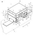
- FIG. 1 is a perspective view showing the appearance of a coil component 1 according to a first embodiment of the present invention, with mounting surfaces 7 and 8 facing upward.
- FIG. 2 is a perspective view showing a mounted state of the coil component 1 shown in FIG. 1.
- FIG. 3 is a perspective view for explaining a typical external force exerted on the coil component 1 in the mounted state shown in FIG. 2.
- FIG. 3 is a perspective view for explaining an external force in the rotational direction that is applied to the coil component 1 in the mounted state shown in FIG. 2.
- FIG. FIG. 7 is a perspective view showing the appearance of a coil component 1a according to a second embodiment of the present invention, with mounting surfaces 7 and 8 facing upward.
- FIG. 7 is a perspective view showing the appearance of a coil component 1b according to a third embodiment of the present invention, with mounting surfaces 7 and 8 facing upward.
- FIG. 7 is a perspective view showing the appearance of a coil component 1c according to a fourth embodiment of the present invention, with mounting surfaces 7 and 8 facing upward.
- FIG. 7 is a perspective view showing the appearance of a coil component 1d according to a fifth embodiment of the present invention, with mounting surfaces 7 and 8 facing upward.
- a coil component 1 according to a first embodiment of the present invention will be described with reference to FIGS. 1 to 4.
- the coil component 1 includes a winding core 2 extending in the axial direction (L direction), and a pair of flanges provided at mutually opposite ends of the winding core 2 in the L direction, that is, first flanges. 3 and a second flange 4, the drum-shaped core 5 is provided.
- the core 5 is made of a magnetic material such as ferrite, a resin containing ferrite powder or metal magnetic powder, or a non-magnetic material such as alumina.
- the winding core 2 has a substantially rectangular cross-sectional shape in the drawings, it may also have a polygonal shape such as a hexagonal shape, a circular shape, an elliptical shape, or a combination thereof.
- the first flange 3 connects a mounting surface 7 that faces the mounting board 6 (see FIG. 2) side during mounting, a top surface 9 that faces the opposite side of the mounting surface 7, and the mounting surface 7 and the top surface 9.
- the inner end surface 11 faces the winding core 2 side and positions the end of the winding core 2 in the L direction
- the outer end surface 13 faces the opposite side of the inner end surface 11, and the inner end surface 11. It has a first side surface 15 and a second side surface 17 that connect the outer end surface 13 and face in opposite directions.
- the second flange 4 connects the mounting surface 8 facing the mounting board 6 side, the top surface 10 facing the opposite side of the mounting surface 8, and the mounting surface 8 and the top surface 10 during mounting.
- the dimensions of the core 5 are not limited, but as an example, the dimension in the L direction is 3.2 mm, which is a direction perpendicular to the L direction and in the direction in which the mounting surfaces 7 and 8 and the top surfaces 9 and 10 extend.
- the dimension in the direction (W direction) is 2.5 mm
- the dimension in the direction (T direction) connecting the mounting surfaces 7 and 8 and the top surfaces 9 and 10 is 1.8 mm.
- the coil component 1 constitutes a wire-wound inductor, for example, and includes a wire 21 wound around the winding core portion 2 of the core 5.
- the wire 21 includes, for example, a center wire made of a highly conductive metal such as copper, silver, or gold, and an insulating coating made of an electrically insulating resin such as polyamideimide, polyurethane, or polyesterimide that covers the center wire.
- the diameter of the center wire of the wire 21 does not matter, it is preferable to use one having a diameter of 80 ⁇ m or more and 200 ⁇ m or less, for example.
- the number of turns of the wire 21 on the winding core 2 does not matter.
- a pair of metal terminals 23 and 24 are attached to the flanges 3 and 4. More specifically, the first metal terminal 23 is attached to the first flange 3 , and the second metal terminal 24 is attached to the second flange 4 .
- the mutually opposite first and second ends of the wire 21 described above are connected to the first metal terminal 23 and the second metal terminal 24, respectively.
- the first metal terminal 23 and the second metal terminal 24 are each made of a single metal plate, and have substantially the same shape or a point-symmetrical shape.
- the metal plates constituting the metal terminals 23 and 24 for example, a plate formed by Ni plating and Sn plating on a base material made of phosphor bronze is used.
- the first metal terminal 23 includes a mounting surface facing portion 25, an outer end surface facing portion 27, and a first side surface facing portion 25 facing the mounting surface 7, the outer end surface 13, the first side surface 15, and the second side surface 17 of the first collar portion 3, respectively. portion 29 and a second side facing portion 31 .
- the second metal terminal 24 includes a mounting surface facing portion 26, an outer end surface facing portion 28, and a first side surface facing portion 26 facing the mounting surface 8, the outer end surface 14, the first side surface 16, and the second side surface 18 of the second collar portion 4, respectively. portion 30 and a second side facing portion 32 .
- the outer end surface facing portion 27 is continuous from the mounting surface facing portion 25 via the first bent portion 33, and the first side surface facing portion 29 and the second side surface facing portion 31 are It continues from the mounting surface facing portion 25 via the second bent portion 35 .
- the outer end face facing part 28 is continuous from the mounting surface facing part 26 via the first bent part 34, and the first side facing part 30 and the second side facing part 32 are connected to the mounting surface facing part 26. It continues from the opposing portion 26 via the second bent portion 36 .
- the first end and the second end of the wire 21 are connected to the mounting surface facing portion 25 of the first metal terminal 23 and the mounting surface facing portion 26 of the second metal terminal 24, respectively, by thermocompression bonding, for example. .
- the coil component 1 is mounted with metal terminals 23 and 24 connected to conductive lands 37 and 38 provided on the mounting board 6 via solder.
- FIG. 2 shows a fillet 39 formed by solder that connects the conductive land 37 and the first metal terminal 23. As shown in FIG.
- a top plate 40 is provided on the coil component 1 so as to connect the top surface 9 of the first flange 3 of the core 5 and the top surface 10 of the second flange 4.
- the top plate 40 is bonded to the core 5 with an adhesive.
- the adhesive for example, a thermosetting epoxy resin is used.
- Inorganic fillers such as silica fillers may be added to the adhesive to improve its thermal shock resistance.
- Examples of adhesive application methods include a printing method in which the adhesive is applied to the top plate 40, a method in which the top surfaces 9 and 10 sides of the flanges 3 and 4 of the core 5 are dipped in adhesive, and a method in which the adhesive is applied to the top plate 40 and the core 5.
- a method such as dispensing adhesive on both sides can be adopted.
- the material for the top plate 40 for example, a magnetic material such as ferrite, a resin containing ferrite powder or metal magnetic powder, or a non-magnetic material such as alumina is used.
- a resin coating may be applied. Note that the top plate 40 and the resin coating may not be provided.
- the first flange portion 3 resists the external force in the direction from the top surfaces 9 and 10 toward the mounting surfaces 7 and 8 in the T direction.
- the resistance can be maintained by the contact between the mounting surface 7 and the mounting surface facing portion 25 of the first metal terminal 23 and the contact between the mounting surface 8 of the second collar portion 4 and the mounting surface facing portion 26 of the second metal terminal 24. can.
- the metal terminals 23 and 24 can withstand external forces in at least the five directions described above without coming off from the flanges 3 and 4.
- This embodiment has a structure that makes it even more difficult for the metal terminals 23 and 24 to come off from the flanges 3 and 4. That is, the metal terminals 23 and 24 further include a regulating part for regulating the movement of at least the mounting surface facing parts 25 and 26 in a direction away from the mounting surfaces 7 and 8 with respect to the collar parts 3 and 4.
- the external forces directed from the mounting surfaces 7 and 8 toward the top surfaces 9 and 10 in the T direction are normally applied when the coil component 1 is mounted on the mounting board. Although this does not occur, it may occur instantaneously due to the impact of a fall, etc.
- the above-mentioned regulating portion is effective against external forces acting on the core 5 from the mounting surfaces 7 and 8 toward the top surfaces 9 and 10 in the T direction.
- the regulating portion includes a first convex portion 41 provided on at least one of the first side surface 15 and the second side surface 17 of the first collar portion 3, and the first metal terminal 23.
- a notch 42 is located on at least one of the first side facing portion 29 and the second side facing portion 31 of the terminal 23 and receives the first convex portion 41.
- the regulating portion includes the first convex portion 43 provided on at least one of the first side surface 16 and the second side surface 18 of the second collar portion 4 and the first convex portion 43 of the second metal terminal 24 .
- a notch 44 is located on at least one of the side facing portion 30 and the second side facing portion 32 and receives the first convex portion 43.
- the first metal terminal 23 receives a relatively large external force.
- a large area can be secured for the outer end surface facing portion 27 and the mounting surface facing portion 25 of the metal terminal 23.
- the same can be said of the notch portion 44 in the second metal terminal 24. Therefore, the effect of making it difficult for the metal terminals 23 and 24 to come off from the flanges 3 and 4 can be further enhanced.
- the first convex portion 41 is provided on both the first side surface 15 and the second side surface 17 of the first collar portion 3, and the notch portion 42 is provided on the first metal terminal 23. It is located on both the first side facing portion 29 and the second side facing portion 31 of 23.
- the second metal terminal 24 the first convex portion 43 is provided on both the first side surface 16 and the second side surface 18 of the second collar portion 4
- the notch portion 44 is provided on the first side surface 16 and the second side surface 18 of the second collar portion 4 . It is located on both the first side facing portion 30 and the second side facing portion 32.
- the first convex portion 41 is provided on both the first side surface 15 and the second side surface 17 of the first collar portion 3, and the first convex portion 43 is provided on both the first side surface 16 and the second side surface of the second collar portion 4.
- the metal terminals 23 and 24 are difficult to come off from the flanges 3 and 4, and the effect can be further enhanced.
- the mounting surface facing portions 25 and 26 not only move in the direction away from the mounting surfaces 7 and 8, but also in the outer end surface. Movement of the opposing parts 27 and 28 in the direction away from the outer end surfaces 13 and 14 can also be restricted.
- the first convex portion 41 has a first rising wall 45 extending along the direction in which the top surface 9 of the first collar portion 3 and the mounting surface 7 face each other, and the outer end surface 13 and a second rising wall 46 extending along the direction in which the inner end surface 11 and the inner end surface 11 face each other, and the cutout portion 42 faces the first opposing wall 47 that faces the first rising wall 45 and the second rising wall 46.
- a second opposing wall 48 is provided.
- the first convex portion 43 has a first rising wall 49 extending along the direction in which the top surface 10 of the second collar portion 4 and the mounting surface 8 face each other, and the outer end surface 14 and the inner end surface. 12 and a second rising wall 50 extending along the opposite direction, the cutout portion 44 provides a first opposing wall 51 facing the first rising wall 49 and a second opposing wall 50 facing the second rising wall 50.
- a wall 52 is provided.
- the contact between the first rising walls 45 and 49 and the first opposing walls 47 and 51 is such that the metal terminals 23 and 24 are in contact with the collar parts 3 and 4, and at least the outer end face facing parts 27 and 28 are in contact with the outer side. Although movement in the direction away from the end faces 13 and 14 is restricted, this state of contact does not necessarily need to be maintained when no external force is applied.
- the first rising walls 45 and 49 extend linearly in parallel with the inner end surfaces 11 and 12, respectively, and the second rising walls Preferably, 46 and 50 extend linearly parallel to mounting surfaces 7 and 8, respectively.
- the first convex portion 41 is connected to the outer end surface 13 and the mounting surface at the first side surface 15 and the second side surface 17.
- the notch portion 42 is located so as to be in contact with the corner where the first metal terminal 23 intersects with the inner end surface 11 side of the first side facing portion 29 and the second side facing portion 31 of the first metal terminal 23 and the top surface 9. It is located at a predetermined distance from the side edge.
- the first side facing portion 29 and the second side facing portion 31 have an L-shape that is biased toward the inner end surface 11 side and the top surface 9 side.
- the first convex portion 43 is connected to the outer end surface 14 on the first side surface 16 and the second side surface 18.
- the notch portion 44 is located so as to be in contact with the corner where the surface 8 intersects, and the notch portion 44 is located at the edge of the first side surface facing portion 30 and the second side surface facing portion 32 of the second metal terminal 24 on the inner end surface 12 side and the top surface. It is located at a predetermined distance from the edge on the 10 side.
- the first side facing portion 30 and the second side facing portion 32 have an L-shape that is biased toward the inner end surface 12 side and the top surface 10 side.
- the area of each of the first protrusions 41 and 43 can be increased. Further, the rising walls along the mounting surfaces 7 and 8 in the first convex portions 41 and 43 are flush with the mounting surfaces 7 and 8, and the rising walls along the outer end surfaces 13 and 14 in the first convex portions 41 and 43 are on the outer end surface. Since it is flush with 13 and 14, it becomes easy to mold the core 5 including the first protrusions 41 and 43.
- the first flange 3 also includes a second convex portion 53 that faces at least a portion of the edge of the first metal terminal 23 on the top surface 9 side in a direction in which the top surface 9 and the mounting surface 7 face each other.
- the second flange 4 further includes a second protrusion that faces at least a portion of the edge of the second metal terminal 24 on the top surface 10 side in a direction in which the top surface 10 and the mounting surface 8 face each other. It is preferable to further include a section 54.
- the external force R1 in the rotational direction is generated around an axis oriented in the W direction
- the external force R2 in the rotational direction is generated around an axis oriented in the L direction.
- the external force R1 is caused by, for example, the difference in thermal expansion between the core 5 and the mounting board 6 when a temperature change occurs in a state where the coil components 1 and the mounting board 6 are mounted. This may occur because the mounting board 6 thermally expands more than the core 5.
- the second convex portion 53 is provided across the first side surface 15, the outer end surface 13, and the second side surface 17 of the first collar portion 3, and the second convex portion 54 is provided over the first side surface 15, the outer end surface 13, and the second side surface 17 of the first collar portion 3. It is provided over the side surface 16, the outer end surface 14, and the second side surface 18.
- the second convex portion 53 is located at the end of the first side surface facing portion 29 and the second side surface facing portion 31 of the first metal terminal 23 on the top surface 9 side.
- the second convex portion 54 is provided so as to face the edge of the first side surface facing portion 30 and the second side surface facing portion 32 of the second metal terminal 24 on the top surface 10 side. Being present is effective.
- outer end surfaces 27 and 28 of the metal terminals 23 and 24 may form a step on the outer end surfaces 13 and 14 side of the flanges 3 and 4, but the outer end surfaces 13 and 14 of the second convex portions 53 and 54 The portion located at contributes to eliminating or reducing such a level difference. Therefore, for example, it is possible to prevent the tip of a tweezers from getting stuck between the opposing outer end surfaces 27 and 28 of the metal terminals 23 and 24 and the outer end surfaces 13 and 14 of the flanges 3 and 4. can.
- FIG. 5 is a diagram corresponding to FIG. 1 , showing a coil component 1d according to an embodiment of the present invention.
- elements corresponding to the elements shown in FIG. 1 or elements corresponding to each other between FIGS. 5 to 8 are given the same reference numerals, and redundant explanation will be omitted.
- the coil component 1a shown in FIG. 5 differs from the coil component 1 shown in FIG. 1 in the shape and bending manner of the metal plates that constitute each of the metal terminals 23a and 24a.
- the outer end surface facing portion 27 is continuous from the mounting surface facing portion 25 via the first bent portion 55, and the first side surface facing portion 29 and the second side surface facing portion 31 are connected to each other via the first bent portion 55. , respectively, are continuous from the outer end face facing portion 27 via the second bent portion 57.
- the outer end surface facing portion 28 is continuous from the mounting surface facing portion 26 via the first bent portion 56, and the first side surface facing portion 30 and the second side surface facing portion 32 are respectively It continues from the outer end surface facing portion 28 via the second bent portion 58 .
- the coil component 1b shown in FIG. 6 can be seen as a modification of the coil component 1a shown in FIG. 5 with respect to the metal terminals 23b and 24b.
- the mounting surface facing portion 25 includes a first mounting surface facing end 61 on the first side surface 15 side, a second mounting surface facing end portion 63 on the second side surface 17 side, and a mounting surface facing central part 65 sandwiched between a first mounting surface facing end 61 and a second mounting surface facing end 63, and these first mounting surface facing end 61 and second mounting surface facing end 63.
- 63 and the mounting surface facing central portion 65 are continuous to the outer end surface facing portion 27 via the first bent portion 55 .
- the mounting surface facing portion 26 includes a first mounting surface facing end 62 on the first side surface 16 side, a second mounting surface facing end portion 64 on the second side surface 18 side, and a first mounting surface facing end portion 64 on the second side surface 18 side. It is divided into a mounting surface facing central part 66 sandwiched between a mounting surface facing end part 62 and a second mounting surface facing end part 64, and these first mounting surface facing end part 62, second mounting surface facing end part 64 and mounting The surface facing central portion 66 is continuous with the outer end surface facing portion 28 via the first bent portion 56 .
- solder is applied to central portions 65 and 66 of the metal terminals 23b and 24b facing the mounting surface.
- the first end of the wire 21 is connected to one of the first mounting surface facing end 61 and the second mounting surface facing end 63, for example, the first mounting surface facing end 61.
- the second end of the wire 21 is connected to one of the first mounting surface facing end 62 and the second mounting surface facing end 64, for example, the second mounting surface facing end 64. be done.
- the first mounting surface facing ends 61 and 62 or the second mounting surface facing ends 63 and 64 are less susceptible to the influence of loads such as heat and stress exerted on the mounting surface facing central parts 65 and 66, and the first mounting surface facing ends 61 and 62 or the second mounting surface facing ends 63 and 64
- the mounting surface facing central portions 65 and 66 can be made less susceptible to loads such as heat and stress applied to the surface facing ends 61 and 62 or the second mounting surface facing ends 63 and 64. Therefore, the connection reliability between the mounting board and the metal terminals 23b and 24b and the connection reliability between the metal terminals 23b and 24b and the wire 21 can be improved.
- the coil component 1c shown in FIG. 7 can be seen as a modification of the coil component 1b shown in FIG. 6 with respect to the metal terminals 23c and 24c.
- the first metal terminal 23c as in the case of the coil component 1b shown in FIG. It is divided into a second mounting surface facing end portion 63 on the side surface 17 side, and a mounting surface facing central portion 65 sandwiched between the first mounting surface facing end portion 61 and the second mounting surface facing end portion 63.
- the mounting surface facing center portion 65 is connected to the outer end surface facing portion 27 via the first bent portion 55, but the first mounting surface facing end portion 61 and the second mounting surface facing end portion 63 are respectively , are connected to the first side facing portion 29 and the second side facing portion 31 via the third bent portion 67.
- the mounting surface facing portion 26 includes a first mounting surface facing end 62 on the first side surface 16 side, a second mounting surface facing end portion 64 on the second side surface 18 side, and a first mounting surface facing end portion 64 on the second side surface 18 side. It is divided into a mounting surface facing central portion 66 sandwiched between a mounting surface facing end portion 62 and a second mounting surface facing end portion 64 .
- the mounting surface facing central portion 66 is connected to the outer end surface facing portion 28 via the first bent portion 56, but the first mounting surface facing end portion 62 and the second mounting surface facing end portion 64 are respectively , are connected to the first side facing portion 30 and the second side facing portion 32 via the third bent portion 68.
- the first end of the wire 21 is connected to one of the first mounting surface facing end 61 and the second mounting surface facing end 63, for example, the first mounting surface facing end 61.
- the second end of the wire 21 is connected to one of the first mounting surface facing end 62 and the second mounting surface facing end 64, for example, the second mounting surface facing end 64. be done.
- the mounting surface facing ends 61 to 64 are separated from each other. However, in the coil component 1c shown in FIG. 7, the mounting surface facing ends 61 to 64 are connected to the outer end surface facing parts 27 and 28 via the side surface facing parts 29 to 32, so Compared to the coil component 1b, the mounting surface facing ends 61 to 64 are less susceptible to the effects of loads such as heat and stress applied to the mounting surface facing central parts 65 and 66, and the mounting surface facing ends 61 to 64 are less affected.
- the central portions 65 and 66 facing the mounting surface are less susceptible to loads such as heat and stress caused by the mounting surface. Therefore, the connection reliability between the mounting board and the metal terminals 23c and 24c, and the connection reliability between the metal terminals 23c and 24c and the wire 21 can be further improved compared to the coil component 1b shown in FIG.
- the coil component 1d shown in FIG. 8 is different from the coil component 1a shown in FIG. 5 in the positions of the first convex portions 41d and 43d.
- the first convex portion 43 is positioned so as to be in contact with the corner where the outer end surface 14 and the mounting surface 8 intersect on the first side surface 16 and the second side surface 18 of the second collar portion 4. It was done.
- the first convex portion 43d is located away from the corner where the outer end surface 14 and the mounting surface 8 intersect on the first side surface 16 and the second side surface 18 of the second collar portion 4.
- first protrusions 41d and 43d are substantially the same as the functions of the first protrusions 41 and 43.
- the coil parts to which this invention is directed include those that constitute a common mode choke coil, transformers, baluns, etc., in addition to those that constitute a single coil as in the illustrated embodiment. It's okay. Therefore, the number of wires can also be changed depending on the function of the coil component, and the number of metal terminals provided on each collar can also be changed accordingly. Typically, two metal terminals may be arranged side by side in the W direction on one flange.
- each metal terminal has a mounting surface facing part facing an area less than half of the width direction dimension of the mounting surface;
- the outer end surface has an outer end surface facing portion that faces an area that is less than half of the widthwise dimension of the outer end surface, and a side surface facing portion that faces one of the first side surface and the second side surface.
- the mounting surface facing part has a mounting connection part that can be connected to a conductor on the mounting board side during mounting and a wire connection part to which a wire can be connected, and the central part facing the mounting surface that becomes the mounting connection part. is less than half the widthwise dimension of the one shown, and has one end facing the mounting surface as a wire connection portion.
- fixing with adhesive is not essential in this invention. Note that fixing with adhesive may encounter the following problems.
- the advantage of metal terminals is that due to the springiness of the metal plate, even if some external force is applied, the metal terminal itself flexes to release the stress and prevent breakage.
- the more firmly the metal terminal is fixed with adhesive the less the springiness of the metal plate can be utilized. In other words, it becomes vulnerable to the development of solder cracks during long-term reliability tests and to deflection tests.
- Adhesives are usually sensitive to heat and lose their adhesive function after being exposed to heat of about 300°C for just a few minutes. However, when manufacturing coil parts using conventional metal terminals, it is necessary to connect the wires to the metal terminals using heat after attaching the metal terminals to the core, so heat is applied to the adhesive. cannot be avoided.
- fixing with adhesive is not essential when attaching the metal terminals 23 and 24 to the flanges 3 and 4, so it is not necessary to apply sufficient heat when connecting the wires to the metal terminals. It is possible. Therefore, a relatively thick wire can be used in the coil component. Note that this invention does not exclude the use of adhesives. Furthermore, in configuring the coil component according to the present invention, partial substitution of the configuration between the different embodiments described in this specification is possible. Or a combination is possible.
- Embodiments of this invention include the following.
- a core having a winding core extending in the axial direction and a pair of flanges provided at mutually opposite ends of the winding core in the axial direction; at least one pair of metal terminals each made of a metal plate attached to each of the flanges; at least one wire connected to each of the at least one pair of metal terminals and wound around the winding core; Equipped with Each of the flange portions connects a mounting surface facing the mounting board during mounting, a top surface facing the opposite side of the mounting surface, and the mounting surface and the top surface, and connects the mounting surface and the top surface.
- Each of the metal terminals includes a mounting surface facing portion facing the mounting surface, an outer end surface facing portion facing the outer end surface, and a side facing portion facing at least one of the first side surface and the second side surface; has a first regulating part for regulating the metal terminal from moving in a direction away from the mounting surface, at least the mounting surface facing part, with respect to the flange; and at least the outer end face facing part moving away from the outer end surface. further comprising a second regulating section for regulating movement in the direction; coil parts.
- the collar portion has a first upright wall extending along the direction in which the inner end surface extends;
- the metal terminal has a first opposing wall that faces the first rising wall,
- the first regulating portion is provided by contact between the first rising wall and the first opposing wall.
- the flange portion has a second rising wall extending along the direction in which the mounting surface extends,
- the metal terminal has a second opposing wall opposite to the second rising wall,
- the second regulating portion is provided by contact between the first rising wall and the first opposing wall.
- a first convex portion is provided on at least one of the first side surface and the second side surface, A cutout portion for receiving the first convex portion is provided in the side facing portion, The first convex portion includes an outer peripheral wall that provides the first rising wall and the second rising wall, The cutout portion includes an inner peripheral wall that provides the first opposing wall and the second opposing wall.
- the outer end surface facing portion is continuous from the mounting surface facing portion via a first bent portion, and the side surface facing portion is continuous from the mounting surface facing portion via a second bent portion, ⁇ 1> to ⁇
- the outer end surface facing portion is continuous from the mounting surface opposing portion via a first bent portion, and the side surface opposing portion is continuous from the outer end surface opposing portion via a second bent portion, ⁇ 1> to ⁇ 1.
- the coil component according to any one of 4>.
- the metal terminal is adjacent to the mounting surface facing portion at at least one end on the first side surface side and the second side surface side of the mounting surface, and has a mounting surface facing end portion facing the mounting surface.
- the coil component according to ⁇ 6> further comprising:
- the first convex portion When viewed toward each of the first side surface and the second side surface, the first convex portion is such that the outer end surface and the mounting surface intersect on at least one of the first side surface and the second side surface. located so as to touch the corner, The cutout portion is located at a predetermined distance from an edge on the inner end surface side and an edge on the top surface side of the side facing portion.
- the coil component described in ⁇ 4> When viewed toward each of the first side surface and the second side surface, the first convex portion is such that the outer end surface and the mounting surface intersect on at least one of the first side surface and the second side surface. located so as to touch the corner, The cutout portion is located at a predetermined distance from an edge on the inner end surface side and an edge on the top surface side of the side facing portion.
- Each of the metal terminals includes, as the side surface facing portions, a first side surface facing portion facing the first side surface and a second side surface facing portion facing the second side surface, which are connected via the outer end surface facing portions;
Abstract
The present invention provides a structure that, in a wire winding type coil part with a structure in which a wire is wound on a core, makes a metal terminal, which is made from a metal plate attached to a flange part of the core, less susceptible to coming off from the flange part. Flange parts (3, 4) of a core (5) are provided with mounting surfaces (7, 8), top surfaces (9, 10), inner end faces (11, 12), outer end faces (13, 14), first side surfaces (15, 16), and second side surfaces (17, 18). Metal terminals (23, 24), which are made from metal plate, are provided with mounting surface facing parts (25, 26), outer end facing parts (27, 28), and side surface facing parts (29, 30, 31, 32) that respectively face a mounting surface, an outer end face and a first side surface and/or a second side surface. A coil part (1) further comprises second restricting parts (45, 47, 49, 51) for restricting movement in the L direction by the metal terminal with respect to the flange part, and first restricting parts (46, 48, 50, 52) for restricting movement in the T direction.
Description
この発明は、コアにワイヤを巻回した構造の巻線型のコイル部品に関するもので、特に、金属板からなる金属端子のコアへの取付け構造に関するものである。
The present invention relates to a wire-wound coil component having a structure in which a wire is wound around a core, and particularly to a structure for attaching a metal terminal made of a metal plate to the core.
たとえば特開2006-4989号公報(特許文献1)には、コアにワイヤを巻回した構造の巻線型のコイル部品が記載されている。より詳細には、コアは、軸線方向に延びる巻芯部および巻芯部の軸線方向での互いに逆の端部にそれぞれ設けられた1対の鍔部を有する。各鍔部には、金属板からなる金属端子が取り付けられる。巻芯部には、ワイヤが巻回され、ワイヤは、金属端子に接続される。
For example, Japanese Patent Application Publication No. 2006-4989 (Patent Document 1) describes a wire-wound coil component having a structure in which a wire is wound around a core. More specifically, the core has a winding core extending in the axial direction and a pair of flanges provided at opposite ends of the winding core in the axial direction. A metal terminal made of a metal plate is attached to each collar. A wire is wound around the winding core, and the wire is connected to a metal terminal.
鍔部は、実装時において実装基板側に向けられる実装面と、実装面の反対側に向く天面と、実装面と天面とを連結するものであって、巻芯部側に向きかつ巻芯部の軸線方向での端部を位置させる内側端面と、内側端面の反対側に向く外側端面と、を有している。
The flange connects the mounting surface facing the mounting board side, the top surface facing the opposite side of the mounting surface, and the mounting surface and the top surface during mounting. It has an inner end surface on which the end of the core portion in the axial direction is located, and an outer end surface facing opposite to the inner end surface.
一方、金属端子は、上記鍔部の実装面、外側端面および天面にそれぞれ対向する実装面対向部、外側端面対向部および天面対向部を有し、実装面対向部から折り曲げ部を介して外側端面対向部へと連なり、外側端面対向部から折り曲げ部を介して天面対向部へと連なっている。
On the other hand, the metal terminal has a mounting surface facing portion, an outer end surface facing portion, and a top surface facing portion that respectively face the mounting surface, the outer end surface, and the top surface of the flange, and is connected to It continues to the outer end face facing part, and from the outer end face facing part to the top face facing part via the bending part.
特許文献1に記載の発明では、鍔部における外側端面と実装面とが成す角度および外側端面と天面とが成す角度の少なくとも一方が鋭角とされ、それによって、実装面対向部と天面対向部とによって鍔部を挟み付けることになり、金属端子が鍔部から外れにくくされている。
In the invention described in Patent Document 1, at least one of the angle between the outer end surface and the mounting surface of the flange and the angle between the outer end surface and the top surface is an acute angle, so that the mounting surface facing part and the top surface are opposite to each other. The flange is sandwiched between the metal terminal and the flange, making it difficult for the metal terminal to come off from the flange.
また、特許文献1には、鍔部の実装面および天面には、開口が円形の凹部が設けられ、金属端子の実装面対向部および天面対向部には、球面をなす凸部が設けられることが記載されている。凹部に凸部がはまり込むことによって、鍔部に対する金属端子の位置決めが容易になり、また、鍔部に対する金属端子の位置ずれが生じにくくなり、このことも金属端子が鍔部から外れにくくすることに寄与する、とされている。
Further, in Patent Document 1, a concave portion with a circular opening is provided on the mounting surface and the top surface of the flange, and a convex portion with a spherical surface is provided on the mounting surface facing portion and the top surface facing portion of the metal terminal. It is stated that By fitting the protrusion into the recess, the metal terminal can be easily positioned with respect to the flange, and the metal terminal is less likely to be misaligned with respect to the flange, which also makes it difficult for the metal terminal to come off the flange. It is said that it contributes to
コアに及ぼされる外力の方向、より特定的には、金属端子が鍔部から外れる原因となる外力の方向には、典型的に、6つの方向があると考えられる。すなわち、巻芯部の軸線方向(以下、「L方向」ともいう。)についての正負2方向、L方向に直交する方向であって、実装面と天面とを結ぶ方向(以下、「T方向」ともいう。)についての正負2方向、ならびに、実装面および天面の延びる方向(以下、「W方向」ともいう。)についての正負2方向である。したがって、金属端子が鍔部から外れないようにするには、これら6つの方向の外力に耐える必要がある。なお、T方向における実装面から天面に向かう外力については、コイル部品が実装基板上に実装された状態では、通常、発生しないが、落下時の衝撃等に起因して、瞬時に発生する可能性がある。
It is thought that there are typically six directions of the external force that is applied to the core, more specifically, the direction of the external force that causes the metal terminal to come off the collar. That is, the two directions are positive and negative with respect to the axial direction of the winding core (hereinafter also referred to as the "L direction"), and the direction perpendicular to the L direction, and the direction connecting the mounting surface and the top surface (hereinafter referred to as the "T direction"). ), and the direction in which the mounting surface and the top surface extend (hereinafter also referred to as the "W direction"). Therefore, in order to prevent the metal terminal from coming off the collar, it is necessary to withstand external forces in these six directions. Note that an external force directed from the mounting surface toward the top surface in the T direction does not normally occur when the coil component is mounted on the mounting board, but it can occur instantaneously due to impact when dropped, etc. There is sex.
特許文献1に記載のコイル部品では、1対の金属端子の各々が、実装面対向部、外側端面対向部および天面対向部を有しているので、T方向における正負の2方向およびL方向における正負の2方向といった4方向の外力には、金属端子の特定の面と鍔部の特定の面とが当接するため、十分耐え得ると考えられる。
In the coil component described in Patent Document 1, each of the pair of metal terminals has a mounting surface facing portion, an outer end surface facing portion, and a top surface facing portion, so that it can be used in two directions, positive and negative in the T direction and in the L direction. It is considered that the external force in four directions (positive and negative directions) can be sufficiently withstood because the specific surface of the metal terminal and the specific surface of the flange come into contact with each other.
一方、コイル部品が実装基板に実装された状態において、温度変化が生じたとき、コアと実装基板との熱膨張差によって、実装基板がコアに比べて、より大きく熱膨張するため、それに追従して、金属端子において、たとえば、W方向に延びる軸線を中心に金属端子を回転させる外力が生じ得る。この回転方向の外力は、金属端子の外側端面対向部をコアの鍔部の外側端面から離そうとする作用をもたらすため、金属端子が鍔部から外れる原因となる。しかしながら、この回転方向の外力に十分に耐え得る構造は、特許文献1に記載のコイル部品には備えられていない。
On the other hand, when a temperature change occurs while the coil component is mounted on the mounting board, the mounting board will thermally expand more than the core due to the difference in thermal expansion between the core and the mounting board. Therefore, an external force may be generated in the metal terminal that rotates the metal terminal around an axis extending in the W direction, for example. This external force in the rotational direction has the effect of separating the outer end surface facing portion of the metal terminal from the outer end surface of the flange of the core, which causes the metal terminal to come off from the flange. However, the coil component described in Patent Document 1 does not have a structure that can sufficiently withstand this external force in the rotational direction.
なお、特許文献1では、前述のように、鍔部の実装面および天面には、開口が円形の凹部が設けられ、金属端子の実装面対向部および天面対向部には、球面をなす凸部が設けられることが記載されている。しかしながら、凹部に凸部がはまり込むことによる外力への抵抗力は比較的弱く、前述した回転方向の外力に十分に対処できるものではないと考えられる。
In addition, in Patent Document 1, as mentioned above, a recess with a circular opening is provided in the mounting surface and the top surface of the collar, and a spherical recess is provided in the mounting surface facing part and the top surface facing part of the metal terminal. It is described that a convex portion is provided. However, the resistance to external force due to the convex portion fitting into the concave portion is relatively weak, and it is considered that the above-mentioned external force in the rotational direction cannot be sufficiently coped with.
そこで、この発明の目的は、特許文献1に記載の技術に比べて、回転方向の外力に、より耐えることができる構造を備えるコイル部品を提供しようとすることである。
Therefore, an object of the present invention is to provide a coil component having a structure that can withstand external force in the rotational direction more than the technology described in Patent Document 1.
この発明は、軸線方向に延びる巻芯部および巻芯部の軸線方向での互いに逆の端部にそれぞれ設けられた1対の鍔部を有する、コアと、各鍔部に取り付けられた、金属板からそれぞれなる少なくとも1対の金属端子と、少なくとも1対の金属端子の各々に接続され、かつ巻芯部に巻回された、少なくとも1本のワイヤと、を備える、コイル部品に向けられる。
The present invention includes a core having a winding core extending in the axial direction and a pair of flanges provided at mutually opposite ends of the winding core in the axial direction, and a metal core attached to each of the flanges. The present invention is directed to a coil component comprising at least one pair of metal terminals each made of a plate, and at least one wire connected to each of the at least one pair of metal terminals and wound around a winding core.
各鍔部は、実装時において実装基板側に向けられる実装面と、実装面の反対側に向く天面と、実装面と天面とを連結するものであって、巻芯部側に向きかつ巻芯部の軸線方向での端部を位置させる内側端面と、内側端面の反対側に向く外側端面と、内側端面と外側端面とを連結しかつ互いに逆方向に向く第1側面および第2側面と、を有する。
Each flange connects the mounting surface facing the mounting board side, the top surface facing the opposite side of the mounting surface, and the mounting surface and the top surface during mounting. an inner end surface on which an end in the axial direction of the winding core is located, an outer end surface facing opposite to the inner end surface, and a first side surface and a second side surface that connect the inner end surface and the outer end surface and face in opposite directions. and has.
この発明において、上述した技術的課題を解決するため、各金属端子は、実装面に対向する実装面対向部と、外側端面に対向する外側端面対向部と、第1側面および第2側面の少なくとも一方に対向する側面対向部と、を有する。そして、金属端子が鍔部に対して、少なくとも外側端面対向部が外側端面から離れる方向(L方向についての一方向)に動くことを規制するための第1規制部、および少なくとも実装面対向部が実装面から離れる方向(T方向についての一方向)に動くことを規制するための第2規制部をさらに備えることを特徴としている。
In this invention, in order to solve the above-mentioned technical problem, each metal terminal has a mounting surface facing portion facing the mounting surface, an outer end surface facing portion facing the outer end surface, and at least one of the first side surface and the second side surface. It has a side facing portion facing one side. The metal terminal includes a first regulating part for regulating movement of at least the outer end face facing part in a direction away from the outer end face (one direction in the L direction) with respect to the flange part, and at least a mounting face facing part. The present invention is characterized in that it further includes a second restriction portion for restricting movement in a direction away from the mounting surface (one direction in the T direction).
この発明によれば、少なくとも外側端面対向部が外側端面から離れる方向(L方向)に動くことを規制するための第1規制部、および少なくとも実装面対向部が実装面から離れる方向(T方向)に動くことを規制するための第2規制部の双方を備えているので、L方向およびT方向の外力に対してだけでなく、W方向に延びる軸線を中心に回転させる外力に対しても、金属端子が鍔部から外れにくくすることができる。W方向に延びる軸線を中心に回転させる外力は、L方向の外力とT方向の外力とを合成したものとみなすことができるからである。
According to this invention, there is provided a first regulating portion for regulating movement of at least the outer end surface facing portion in a direction away from the outer end surface (L direction), and a direction in which at least the mounting surface opposing portion moves away from the mounting surface (T direction). Since it is provided with both second regulating parts for regulating movement in the direction, it can not only resist external forces in the L direction and the T direction, but also resist external forces that cause rotation around an axis extending in the W direction. The metal terminal can be made difficult to come off from the flange. This is because the external force that causes rotation around the axis extending in the W direction can be considered as a combination of the external force in the L direction and the external force in the T direction.
図1ないし図4を参照して、この発明の第1の実施形態によるコイル部品1について説明する。
A coil component 1 according to a first embodiment of the present invention will be described with reference to FIGS. 1 to 4.
コイル部品1は、軸線方向(L方向)に延びる巻芯部2、ならびに巻芯部2のL方向での互いに逆の端部にそれぞれ設けられた1対の鍔部、すなわち、第1鍔部3および第2鍔部4を有する、ドラム状のコア5を備えている。コア5は、たとえばフェライトなどの磁性体、フェライト粉もしくは金属磁性粉を含有する樹脂、またはアルミナなどの非磁性体から構成される。巻芯部2は、図示では横断面形状がほぼ四角形状であるが、その他、六角形状などの多角形状、円形状、楕円形状、またはこれらを組み合わせた形状であってもよい。
The coil component 1 includes a winding core 2 extending in the axial direction (L direction), and a pair of flanges provided at mutually opposite ends of the winding core 2 in the L direction, that is, first flanges. 3 and a second flange 4, the drum-shaped core 5 is provided. The core 5 is made of a magnetic material such as ferrite, a resin containing ferrite powder or metal magnetic powder, or a non-magnetic material such as alumina. Although the winding core 2 has a substantially rectangular cross-sectional shape in the drawings, it may also have a polygonal shape such as a hexagonal shape, a circular shape, an elliptical shape, or a combination thereof.
第1鍔部3は、実装時において実装基板6(図2参照)側に向けられる実装面7と、実装面7の反対側に向く天面9と、実装面7と天面9とを連結するものであって、巻芯部2側に向きかつ巻芯部2のL方向での端部を位置させる内側端面11と、内側端面11の反対側に向く外側端面13と、内側端面11と外側端面13とを連結しかつ互いに逆方向に向く第1側面15および第2側面17と、を有している。
The first flange 3 connects a mounting surface 7 that faces the mounting board 6 (see FIG. 2) side during mounting, a top surface 9 that faces the opposite side of the mounting surface 7, and the mounting surface 7 and the top surface 9. The inner end surface 11 faces the winding core 2 side and positions the end of the winding core 2 in the L direction, the outer end surface 13 faces the opposite side of the inner end surface 11, and the inner end surface 11. It has a first side surface 15 and a second side surface 17 that connect the outer end surface 13 and face in opposite directions.
同様に、第2鍔部4は、実装時において実装基板6側に向けられる実装面8と、実装面8の反対側に向く天面10と、実装面8と天面10とを連結するものであって、巻芯部2側に向きかつ巻芯部2のL方向での端部を位置させる内側端面12と、内側端面12の反対側に向く外側端面14と、内側端面12と外側端面14とを連結しかつ互いに逆方向に向く第1側面16および第2側面18と、を有している。
Similarly, the second flange 4 connects the mounting surface 8 facing the mounting board 6 side, the top surface 10 facing the opposite side of the mounting surface 8, and the mounting surface 8 and the top surface 10 during mounting. An inner end surface 12 facing the winding core 2 side and on which the end of the winding core 2 in the L direction is located, an outer end surface 14 facing the opposite side of the inner end surface 12, and the inner end surface 12 and the outer end surface. 14 and a first side surface 16 and a second side surface 18 facing in opposite directions.
コア5の寸法は限定されるものではないが、一例として、L方向での寸法が3.2mm、L方向に直交する方向であって、実装面7および8ならびに天面9および10の延びる方向(W方向)での寸法が2.5mm、実装面7および8と天面9および10とを結ぶ方向(T方向)での寸法が1.8mmとされる。
The dimensions of the core 5 are not limited, but as an example, the dimension in the L direction is 3.2 mm, which is a direction perpendicular to the L direction and in the direction in which the mounting surfaces 7 and 8 and the top surfaces 9 and 10 extend. The dimension in the direction (W direction) is 2.5 mm, and the dimension in the direction (T direction) connecting the mounting surfaces 7 and 8 and the top surfaces 9 and 10 is 1.8 mm.
コイル部品1は、たとえば、巻線型インダクタを構成するもので、コア5の巻芯部2に巻回されるワイヤ21を備えている。ワイヤ21は、たとえば、銅、銀または金などの良導電性金属からなる中心線材と、中心線材を覆うポリアミドイミド、ポリウレタンまたはポリエステルイミドのような電気絶縁性樹脂からなる絶縁被膜と、を備える。ワイヤ21の中心線材の径は問わないが、たとえば、径80μm以上かつ200μm以下のものを用いることが好ましい。また、ワイヤ21の巻芯部2上でのターン数は問わない。
The coil component 1 constitutes a wire-wound inductor, for example, and includes a wire 21 wound around the winding core portion 2 of the core 5. The wire 21 includes, for example, a center wire made of a highly conductive metal such as copper, silver, or gold, and an insulating coating made of an electrically insulating resin such as polyamideimide, polyurethane, or polyesterimide that covers the center wire. Although the diameter of the center wire of the wire 21 does not matter, it is preferable to use one having a diameter of 80 μm or more and 200 μm or less, for example. Moreover, the number of turns of the wire 21 on the winding core 2 does not matter.
鍔部3および4には、1対の金属端子23および24が取り付けられる。より具体的は、第1鍔部3には第1金属端子23が取り付けられ、第2鍔部4には第2金属端子24が取り付けられる。上述したワイヤ21の互いに逆の第1端部および第2端部は、それぞれ、第1金属端子23および第2金属端子24に接続される。
A pair of metal terminals 23 and 24 are attached to the flanges 3 and 4. More specifically, the first metal terminal 23 is attached to the first flange 3 , and the second metal terminal 24 is attached to the second flange 4 . The mutually opposite first and second ends of the wire 21 described above are connected to the first metal terminal 23 and the second metal terminal 24, respectively.
第1金属端子23および第2金属端子24は、それぞれ、1枚の金属板からなり、互いに実質的に同じ形状または点対称の形状を有している。金属端子23および24を構成する金属板としては、たとえば、リン青銅からなる母材上にNiめっきおよびSnめっきが施された板が用いられる。
The first metal terminal 23 and the second metal terminal 24 are each made of a single metal plate, and have substantially the same shape or a point-symmetrical shape. As the metal plates constituting the metal terminals 23 and 24, for example, a plate formed by Ni plating and Sn plating on a base material made of phosphor bronze is used.
第1金属端子23は、第1鍔部3の実装面7、外側端面13、第1側面15および第2側面17にそれぞれ対向する実装面対向部25、外側端面対向部27、第1側面対向部29および第2側面対向部31を有する。第2金属端子24は、第2鍔部4の実装面8、外側端面14、第1側面16および第2側面18にそれぞれ対向する実装面対向部26、外側端面対向部28、第1側面対向部30および第2側面対向部32を有する。
The first metal terminal 23 includes a mounting surface facing portion 25, an outer end surface facing portion 27, and a first side surface facing portion 25 facing the mounting surface 7, the outer end surface 13, the first side surface 15, and the second side surface 17 of the first collar portion 3, respectively. portion 29 and a second side facing portion 31 . The second metal terminal 24 includes a mounting surface facing portion 26, an outer end surface facing portion 28, and a first side surface facing portion 26 facing the mounting surface 8, the outer end surface 14, the first side surface 16, and the second side surface 18 of the second collar portion 4, respectively. portion 30 and a second side facing portion 32 .
この実施形態では、第1金属端子23において、外側端面対向部27は、実装面対向部25から第1折り曲げ部33を介して連なり、第1側面対向部29および第2側面対向部31は、実装面対向部25から第2折り曲げ部35を介して連なっている。同様に、第2金属端子24において、外側端面対向部28は、実装面対向部26から第1折り曲げ部34を介して連なり、第1側面対向部30および第2側面対向部32は、実装面対向部26から第2折り曲げ部36を介して連なっている。
In this embodiment, in the first metal terminal 23, the outer end surface facing portion 27 is continuous from the mounting surface facing portion 25 via the first bent portion 33, and the first side surface facing portion 29 and the second side surface facing portion 31 are It continues from the mounting surface facing portion 25 via the second bent portion 35 . Similarly, in the second metal terminal 24, the outer end face facing part 28 is continuous from the mounting surface facing part 26 via the first bent part 34, and the first side facing part 30 and the second side facing part 32 are connected to the mounting surface facing part 26. It continues from the opposing portion 26 via the second bent portion 36 .
ワイヤ21の第1端部および第2端部は、それぞれ、第1金属端子23の実装面対向部25および第2金属端子24の実装面対向部26に対して、たとえば熱圧着によって接続される。
The first end and the second end of the wire 21 are connected to the mounting surface facing portion 25 of the first metal terminal 23 and the mounting surface facing portion 26 of the second metal terminal 24, respectively, by thermocompression bonding, for example. .
コイル部品1は、図2に示すように、実装基板6に設けられた導電ランド37および38に、はんだを介して、金属端子23および24が接続された状態で実装される。図2には、導電ランド37と第1金属端子23とを接続するはんだによって形成されたフィレット39が図示されている。
As shown in FIG. 2, the coil component 1 is mounted with metal terminals 23 and 24 connected to conductive lands 37 and 38 provided on the mounting board 6 via solder. FIG. 2 shows a fillet 39 formed by solder that connects the conductive land 37 and the first metal terminal 23. As shown in FIG.
コイル部品1には、コア5の第1鍔部3の天面9および第2鍔部4の天面10の間を連結するように、天板40が設けられる。天板40はコア5に接着剤によって接合される。接着剤としては、たとえば熱硬化性のあるエポキシ樹脂が用いられる。接着剤の熱衝撃耐性向上のため、シリカフィラーのような無機フィラーが接着剤に添加されてもよい。接着剤の塗布方法としては、天板40に接着剤を塗布する印刷法、コア5の鍔部3および4の天面9および10側を接着剤にディップする方法、天板40およびコア5の双方に接着剤をディスペンス塗布する方法などを採用することができる。
A top plate 40 is provided on the coil component 1 so as to connect the top surface 9 of the first flange 3 of the core 5 and the top surface 10 of the second flange 4. The top plate 40 is bonded to the core 5 with an adhesive. As the adhesive, for example, a thermosetting epoxy resin is used. Inorganic fillers such as silica fillers may be added to the adhesive to improve its thermal shock resistance. Examples of adhesive application methods include a printing method in which the adhesive is applied to the top plate 40, a method in which the top surfaces 9 and 10 sides of the flanges 3 and 4 of the core 5 are dipped in adhesive, and a method in which the adhesive is applied to the top plate 40 and the core 5. A method such as dispensing adhesive on both sides can be adopted.
天板40の材料としては、たとえばフェライトなどの磁性体、フェライト粉もしくは金属磁性粉を含有する樹脂、またはアルミナなどの非磁性体が用いられる。コア5および天板40が双方とも磁性体から構成される場合、コア5および天板40は閉磁路を構成する。天板40に代えて、樹脂によるコーティングが施されてもよい。なお、天板40がなくても、樹脂コートがなくてもよい。
As the material for the top plate 40, for example, a magnetic material such as ferrite, a resin containing ferrite powder or metal magnetic powder, or a non-magnetic material such as alumina is used. When the core 5 and the top plate 40 are both made of magnetic material, the core 5 and the top plate 40 constitute a closed magnetic path. Instead of the top plate 40, a resin coating may be applied. Note that the top plate 40 and the resin coating may not be provided.
以上説明した構成によれば、以下のような作用効果が奏される。
According to the configuration described above, the following effects are achieved.
図1ないし図4を参照して説明すると、コイル部品1の実装状態において、コア5に及ぼされる外力のうち、L方向についての正負2方向の外力に対しては、第1鍔部3の外側端面13と第1金属端子23の外側端面対向部27との当接、および第2鍔部4の外側端面14と第2金属端子24の外側端面対向部28との当接によって耐えることができる。
To explain with reference to FIGS. 1 to 4, when the coil component 1 is mounted, among the external forces exerted on the core 5, external forces in two directions, positive and negative in the L direction, are applied to the outside of the first flange 3. This can be sustained by the contact between the end surface 13 and the outer end surface facing portion 27 of the first metal terminal 23 and the contact between the outer end surface 14 of the second collar portion 4 and the outer end surface facing portion 28 of the second metal terminal 24. .
また、コイル部品1の実装状態において、コア5に及ぼされる外力のうち、W方向についての正負2方向の外力に対しては、第1鍔部3の第1側面15と第1金属端子23の第1側面対向部29との当接、第1鍔部3の第2側面17と第1金属端子23の第2側面対向部31との当接、第2鍔部4の第1側面16と第2金属端子24の第1側面対向部30との当接、および第2鍔部4の第2側面18と第2金属端子24の第2側面対向部32との当接によって耐えることができる。
In addition, in the mounted state of the coil component 1, among the external forces exerted on the core 5, external forces in two directions, positive and negative in the W direction, are applied to the first side surface 15 of the first collar portion 3 and the first metal terminal 23. Contact with the first side surface facing portion 29 , contact between the second side surface 17 of the first collar portion 3 and the second side surface facing portion 31 of the first metal terminal 23 , and contact with the first side surface 16 of the second collar portion 4 . It can be withstood by contact with the first side surface facing portion 30 of the second metal terminal 24 and contact between the second side surface 18 of the second collar portion 4 and the second side surface facing portion 32 of the second metal terminal 24. .
また、コイル部品1の実装状態において、コア5に及ぼされる外力のうち、T方向についての天面9および10から実装面7および8に向かう方向の外力に対しては、第1鍔部3の実装面7と第1金属端子23の実装面対向部25との当接、および第2鍔部4の実装面8と第2金属端子24の実装面対向部26との当接によって耐えることができる。
In addition, in the mounted state of the coil component 1, among the external forces exerted on the core 5, the first flange portion 3 resists the external force in the direction from the top surfaces 9 and 10 toward the mounting surfaces 7 and 8 in the T direction. The resistance can be maintained by the contact between the mounting surface 7 and the mounting surface facing portion 25 of the first metal terminal 23 and the contact between the mounting surface 8 of the second collar portion 4 and the mounting surface facing portion 26 of the second metal terminal 24. can.
以上のようにして、少なくとも上記5方向の外力に対して、金属端子23および24が鍔部3および4から外れないように耐えることができる。
As described above, the metal terminals 23 and 24 can withstand external forces in at least the five directions described above without coming off from the flanges 3 and 4.
この実施形態では、金属端子23および24が鍔部3および4から、より一層外れにくくし得る構造を備えている。すなわち、金属端子23および24が鍔部3および4に対して、少なくとも実装面対向部25および26が実装面7および8から離れる方向に動くことを規制するための規制部をさらに備えている。
This embodiment has a structure that makes it even more difficult for the metal terminals 23 and 24 to come off from the flanges 3 and 4. That is, the metal terminals 23 and 24 further include a regulating part for regulating the movement of at least the mounting surface facing parts 25 and 26 in a direction away from the mounting surfaces 7 and 8 with respect to the collar parts 3 and 4.
前述したように、コア5に及ぼされる外力のうち、T方向における実装面7および8から天面9および10に向かう外力については、コイル部品1が実装基板上に実装された状態では、通常、発生しないが、落下時の衝撃等に起因して、瞬時に発生する可能性がある。上述の規制部は、コア5に及ぼされる外力のうち、T方向における実装面7および8から天面9および10に向かう外力に対して有効である。
As mentioned above, among the external forces exerted on the core 5, the external forces directed from the mounting surfaces 7 and 8 toward the top surfaces 9 and 10 in the T direction are normally applied when the coil component 1 is mounted on the mounting board. Although this does not occur, it may occur instantaneously due to the impact of a fall, etc. The above-mentioned regulating portion is effective against external forces acting on the core 5 from the mounting surfaces 7 and 8 toward the top surfaces 9 and 10 in the T direction.
より具体的には、当該規制部は、第1金属端子23に関しては、第1鍔部3の第1側面15および第2側面17の少なくとも一方に設けられる第1凸部41と、第1金属端子23の第1側面対向部29および第2側面対向部31の少なくとも一方に位置し、かつ第1凸部41を受け入れる切り欠き部42と、によって与えられる。
More specifically, with respect to the first metal terminal 23, the regulating portion includes a first convex portion 41 provided on at least one of the first side surface 15 and the second side surface 17 of the first collar portion 3, and the first metal terminal 23. A notch 42 is located on at least one of the first side facing portion 29 and the second side facing portion 31 of the terminal 23 and receives the first convex portion 41.
また、第2金属端子24に関しては、規制部は、第2鍔部4の第1側面16および第2側面18の少なくとも一方に設けられる第1凸部43と、第2金属端子24の第1側面対向部30および第2側面対向部32の少なくとも一方に位置し、かつ第1凸部43を受け入れる切り欠き部44と、によって与えられる。
Further, regarding the second metal terminal 24 , the regulating portion includes the first convex portion 43 provided on at least one of the first side surface 16 and the second side surface 18 of the second collar portion 4 and the first convex portion 43 of the second metal terminal 24 . A notch 44 is located on at least one of the side facing portion 30 and the second side facing portion 32 and receives the first convex portion 43.
このように、切り欠き部42が設けられる位置として、第1金属端子23の第1側面対向部29および第2側面対向部31の少なくとも一方が選ばれることにより、外力を比較的大きく受ける第1金属端子23の外側端面対向部27および実装面対向部25の面積を広く確保することができる。第2金属端子24における切り欠き部44についても同様のことが言える。したがって、金属端子23および24を鍔部3および4から外れにくくする効果をより高めることができる。
In this way, by selecting at least one of the first side surface facing portion 29 and the second side surface facing portion 31 of the first metal terminal 23 as the position where the notch portion 42 is provided, the first metal terminal 23 receives a relatively large external force. A large area can be secured for the outer end surface facing portion 27 and the mounting surface facing portion 25 of the metal terminal 23. The same can be said of the notch portion 44 in the second metal terminal 24. Therefore, the effect of making it difficult for the metal terminals 23 and 24 to come off from the flanges 3 and 4 can be further enhanced.
この実施形態では、第1金属端子23に関して、第1凸部41は、第1鍔部3の第1側面15および第2側面17の双方に設けられ、切り欠き部42は、第1金属端子23の第1側面対向部29および第2側面対向部31の双方に位置している。また、第2金属端子24に関して、第1凸部43は、第2鍔部4の第1側面16および第2側面18の双方に設けられ、切り欠き部44は、第2金属端子24の第1側面対向部30および第2側面対向部32の双方に位置している。
In this embodiment, regarding the first metal terminal 23, the first convex portion 41 is provided on both the first side surface 15 and the second side surface 17 of the first collar portion 3, and the notch portion 42 is provided on the first metal terminal 23. It is located on both the first side facing portion 29 and the second side facing portion 31 of 23. Further, regarding the second metal terminal 24 , the first convex portion 43 is provided on both the first side surface 16 and the second side surface 18 of the second collar portion 4 , and the notch portion 44 is provided on the first side surface 16 and the second side surface 18 of the second collar portion 4 . It is located on both the first side facing portion 30 and the second side facing portion 32.
このように、第1凸部41が第1鍔部3の第1側面15および第2側面17の双方に設けられ、第1凸部43が第2鍔部4の第1側面16および第2側面18の双方に設けられていると、金属端子23および24を鍔部3および4から外れにくく効果をより高めることができる。
In this way, the first convex portion 41 is provided on both the first side surface 15 and the second side surface 17 of the first collar portion 3, and the first convex portion 43 is provided on both the first side surface 16 and the second side surface of the second collar portion 4. When provided on both side surfaces 18, the metal terminals 23 and 24 are difficult to come off from the flanges 3 and 4, and the effect can be further enhanced.
上述したような第1凸部41および43と切り欠き部42および44との組み合わせによる規制部によれば、実装面対向部25および26が実装面7および8から離れる方向だけでなく、外側端面対向部27および28が外側端面13および14から離れる方向にも動くことを規制することができる。
According to the restriction portion formed by the combination of the first convex portions 41 and 43 and the cutout portions 42 and 44 as described above, the mounting surface facing portions 25 and 26 not only move in the direction away from the mounting surfaces 7 and 8, but also in the outer end surface. Movement of the opposing parts 27 and 28 in the direction away from the outer end surfaces 13 and 14 can also be restricted.
この実施形態では、第1金属端子23に関して、第1凸部41は、第1鍔部3の天面9と実装面7とが対向する方向に沿って延びる第1立上がり壁45と外側端面13と内側端面11とが対向する方向に沿って延びる第2立上がり壁46とを与え、切り欠き部42は、第1立上がり壁45に対向する第1対向壁47と第2立上がり壁46に対向する第2対向壁48とを与えている。
In this embodiment, regarding the first metal terminal 23, the first convex portion 41 has a first rising wall 45 extending along the direction in which the top surface 9 of the first collar portion 3 and the mounting surface 7 face each other, and the outer end surface 13 and a second rising wall 46 extending along the direction in which the inner end surface 11 and the inner end surface 11 face each other, and the cutout portion 42 faces the first opposing wall 47 that faces the first rising wall 45 and the second rising wall 46. A second opposing wall 48 is provided.
また、第2金属端子24に関して、第1凸部43は、第2鍔部4の天面10と実装面8とが対向する方向に沿って延びる第1立上がり壁49と外側端面14と内側端面12とが対向する方向に沿って延びる第2立上がり壁50とを与え、切り欠き部44は、第1立上がり壁49に対向する第1対向壁51と第2立上がり壁50に対向する第2対向壁52とを与えている。
Regarding the second metal terminal 24, the first convex portion 43 has a first rising wall 49 extending along the direction in which the top surface 10 of the second collar portion 4 and the mounting surface 8 face each other, and the outer end surface 14 and the inner end surface. 12 and a second rising wall 50 extending along the opposite direction, the cutout portion 44 provides a first opposing wall 51 facing the first rising wall 49 and a second opposing wall 50 facing the second rising wall 50. A wall 52 is provided.
なお、第1立上がり壁45および49と第1対向壁47および51との当接は、それぞれ、金属端子23および24が鍔部3および4に対して、少なくとも外側端面対向部27および28が外側端面13および14から離れる方向に動くことを規制するものであるが、外力が加わっていない状態では、必ずしも、この当接状態は維持される必要はない。
Note that the contact between the first rising walls 45 and 49 and the first opposing walls 47 and 51 is such that the metal terminals 23 and 24 are in contact with the collar parts 3 and 4, and at least the outer end face facing parts 27 and 28 are in contact with the outer side. Although movement in the direction away from the end faces 13 and 14 is restricted, this state of contact does not necessarily need to be maintained when no external force is applied.
第1側面15および16ならびに第2側面17および18の各々に向かって見たとき、第1立上がり壁45および49は、それぞれ、内側端面11および12と平行に直線状に延び、第2立上がり壁46および50は、それぞれ、実装面7および8と平行に直線状に延びていることが好ましい。
When viewed toward each of the first side surfaces 15 and 16 and the second side surfaces 17 and 18, the first rising walls 45 and 49 extend linearly in parallel with the inner end surfaces 11 and 12, respectively, and the second rising walls Preferably, 46 and 50 extend linearly parallel to mounting surfaces 7 and 8, respectively.
このように、第1立上がり壁45および49が内側端面11および12と平行に直線状に延び、第2立上がり壁46および50が実装面7および8と平行に直線状に延びていると、実装面対向部25および26が実装面7および8から離れる方向と、外側端面対向部27および28が外側端面13および14から離れる方向と、に対して、力の偏りなく、金属端子23および24が鍔部3および4から外れることを確実に抑制することができる。
In this way, when the first rising walls 45 and 49 extend linearly parallel to the inner end surfaces 11 and 12, and the second rising walls 46 and 50 extend linearly parallel to the mounting surfaces 7 and 8, mounting The metal terminals 23 and 24 are moved in the direction in which the surface facing parts 25 and 26 move away from the mounting surfaces 7 and 8 and the direction in which the outer end face facing parts 27 and 28 move away from the outer end faces 13 and 14 without biasing the force. It is possible to reliably prevent it from coming off from the flanges 3 and 4.
また、第1鍔部3の第1側面15および第2側面17の各々に向かって見たとき、第1凸部41は、第1側面15および第2側面17において、外側端面13と実装面7とが交差する角に接するように位置され、切り欠き部42は、第1金属端子23の第1側面対向部29および第2側面対向部31における内側端面11側の端縁および天面9側の端縁から所定の距離を置いて位置されている。言い換えると、第1側面対向部29および第2側面対向部31は、内側端面11側および天面9側に片寄ったL字状をなしている。
Further, when viewed toward each of the first side surface 15 and the second side surface 17 of the first flange portion 3, the first convex portion 41 is connected to the outer end surface 13 and the mounting surface at the first side surface 15 and the second side surface 17. The notch portion 42 is located so as to be in contact with the corner where the first metal terminal 23 intersects with the inner end surface 11 side of the first side facing portion 29 and the second side facing portion 31 of the first metal terminal 23 and the top surface 9. It is located at a predetermined distance from the side edge. In other words, the first side facing portion 29 and the second side facing portion 31 have an L-shape that is biased toward the inner end surface 11 side and the top surface 9 side.
同様に、第2鍔部4の第1側面16および第2側面18の各々に向かって見たとき、第1凸部43は、第1側面16および第2側面18において、外側端面14と実装面8とが交差する角に接するように位置され、切り欠き部44は、第2金属端子24の第1側面対向部30および第2側面対向部32における内側端面12側の端縁および天面10側の端縁から所定の距離を置いて位置されている。言い換えると、第1側面対向部30および第2側面対向部32は、内側端面12側および天面10側に片寄ったL字状をなしている。
Similarly, when viewed toward each of the first side surface 16 and second side surface 18 of the second flange portion 4, the first convex portion 43 is connected to the outer end surface 14 on the first side surface 16 and the second side surface 18. The notch portion 44 is located so as to be in contact with the corner where the surface 8 intersects, and the notch portion 44 is located at the edge of the first side surface facing portion 30 and the second side surface facing portion 32 of the second metal terminal 24 on the inner end surface 12 side and the top surface. It is located at a predetermined distance from the edge on the 10 side. In other words, the first side facing portion 30 and the second side facing portion 32 have an L-shape that is biased toward the inner end surface 12 side and the top surface 10 side.
上述したような第1凸部41および43ならびに切り欠き部42および44の配置によれば、第1凸部41および43の各々の面積を大きく取ることができる。また、第1凸部41および43における実装面7および8に沿う立上がり壁が実装面7および8と面一となり、第1凸部41および43における外側端面13および14に沿う立上がり壁が外側端面13および14と面一となるので、第1凸部41および43を備えるコア5の成形が容易になる。
According to the arrangement of the first protrusions 41 and 43 and the notches 42 and 44 as described above, the area of each of the first protrusions 41 and 43 can be increased. Further, the rising walls along the mounting surfaces 7 and 8 in the first convex portions 41 and 43 are flush with the mounting surfaces 7 and 8, and the rising walls along the outer end surfaces 13 and 14 in the first convex portions 41 and 43 are on the outer end surface. Since it is flush with 13 and 14, it becomes easy to mold the core 5 including the first protrusions 41 and 43.
また、第1鍔部3は、第1金属端子23の天面9側の端縁の少なくとも一部に対して、天面9と実装面7とが対向する方向に対向する第2凸部53をさらに備え、第2鍔部4は、第2金属端子24の天面10側の端縁の少なくとも一部に対して、天面10と実装面8とが対向する方向に対向する第2凸部54をさらに備えていることが好ましい。
The first flange 3 also includes a second convex portion 53 that faces at least a portion of the edge of the first metal terminal 23 on the top surface 9 side in a direction in which the top surface 9 and the mounting surface 7 face each other. The second flange 4 further includes a second protrusion that faces at least a portion of the edge of the second metal terminal 24 on the top surface 10 side in a direction in which the top surface 10 and the mounting surface 8 face each other. It is preferable to further include a section 54.
このような第2凸部53および54によれば、図4に示した回転方向の外力R1およびR2に対して、金属端子23および24が鍔部3および4から外れることをより確実に抑制できる。回転方向の外力R1は、W方向に向く軸線まわりに生じるものであり、回転方向の外力R2は、L方向に向く軸線まわりに生じるものである。これら回転方向の外力R1およびR2のうち、外力R1は、たとえば、コイル部品1およびが実装基板6に実装された状態において、温度変化が生じたとき、コア5と実装基板6との熱膨張差によって、実装基板6がコア5に比べて、より大きく熱膨張することによって生じ得る。これら回転方向の外力R1およびR2は、金属端子23および24の外側端面対向部27および28をコア5から離そうとする作用をもたらすため、金属端子23および24が鍔部3および4から外れる原因となる。
According to such second convex portions 53 and 54, it is possible to more reliably suppress metal terminals 23 and 24 from coming off from collar portions 3 and 4 in response to external forces R1 and R2 in the rotational direction shown in FIG. . The external force R1 in the rotational direction is generated around an axis oriented in the W direction, and the external force R2 in the rotational direction is generated around an axis oriented in the L direction. Of these external forces R1 and R2 in the rotational direction, the external force R1 is caused by, for example, the difference in thermal expansion between the core 5 and the mounting board 6 when a temperature change occurs in a state where the coil components 1 and the mounting board 6 are mounted. This may occur because the mounting board 6 thermally expands more than the core 5. These external forces R1 and R2 in the rotational direction cause the metal terminals 23 and 24 to come off from the flanges 3 and 4 because they have the effect of trying to separate the outer end face opposing parts 27 and 28 of the metal terminals 23 and 24 from the core 5. becomes.
この実施形態では、第2凸部53は、第1鍔部3における第1側面15、外側端面13および第2側面17にわたって設けられ、第2凸部54は、第2鍔部4における第1側面16、外側端面14および第2側面18にわたって設けられている。
In this embodiment, the second convex portion 53 is provided across the first side surface 15, the outer end surface 13, and the second side surface 17 of the first collar portion 3, and the second convex portion 54 is provided over the first side surface 15, the outer end surface 13, and the second side surface 17 of the first collar portion 3. It is provided over the side surface 16, the outer end surface 14, and the second side surface 18.
上述した回転方向の外力R1およびR2に対する抵抗力という点では、特に、第2凸部53が第1金属端子23の第1側面対向部29および第2側面対向部31における天面9側の端縁に対向するように設けられ、第2凸部54が第2金属端子24の第1側面対向部30および第2側面対向部32における天面10側の端縁に対向するように設けられていることが効果的である。
In terms of the resistance force against the external forces R1 and R2 in the rotational direction described above, in particular, the second convex portion 53 is located at the end of the first side surface facing portion 29 and the second side surface facing portion 31 of the first metal terminal 23 on the top surface 9 side. The second convex portion 54 is provided so as to face the edge of the first side surface facing portion 30 and the second side surface facing portion 32 of the second metal terminal 24 on the top surface 10 side. Being present is effective.
なお、金属端子23および24の外側端面対向部27および28は、鍔部3および4の外側端面13および14側において段差を形成し得るが、第2凸部53および54における外側端面13および14に位置する部分は、このような段差の解消または低減に寄与する。したがって、たとえばピンセットなどの先端が、金属端子23および24の外側端面対向部27および28と、鍔部3および4の外側端面13および14と、の間に入り込むような不都合を生じにくくすることができる。
Note that the outer end surfaces 27 and 28 of the metal terminals 23 and 24 may form a step on the outer end surfaces 13 and 14 side of the flanges 3 and 4, but the outer end surfaces 13 and 14 of the second convex portions 53 and 54 The portion located at contributes to eliminating or reducing such a level difference. Therefore, for example, it is possible to prevent the tip of a tweezers from getting stuck between the opposing outer end surfaces 27 and 28 of the metal terminals 23 and 24 and the outer end surfaces 13 and 14 of the flanges 3 and 4. can.
図5、図6、図7および図8は、それぞれ、この発明の第2の実施形態によるコイル部品1a、第3の実施形態によるコイル部品1b、第4の実施形態によるコイル部品1cおよび第5の実施形態によるコイル部品1dを示す、図1に相当する図である。図5ないし図8において、図1に示した要素に相当する要素、または図5ないし図8相互間で相当する要素には同様の参照符号を付し、重複する説明を省略する。
5, 6, 7 and 8 respectively show a coil component 1a according to a second embodiment of the present invention, a coil component 1b according to a third embodiment, a coil component 1c according to a fourth embodiment, and a fifth embodiment. FIG. 2 is a diagram corresponding to FIG. 1 , showing a coil component 1d according to an embodiment of the present invention. In FIGS. 5 to 8, elements corresponding to the elements shown in FIG. 1 or elements corresponding to each other between FIGS. 5 to 8 are given the same reference numerals, and redundant explanation will be omitted.
図5に示したコイル部品1aは、図1に示したコイル部品1とは、金属端子23aおよび24aの各々を構成する金属板の形状および折り曲げ態様が異なっている。
The coil component 1a shown in FIG. 5 differs from the coil component 1 shown in FIG. 1 in the shape and bending manner of the metal plates that constitute each of the metal terminals 23a and 24a.
より具体的には、第1金属端子23aにおいて、外側端面対向部27は、実装面対向部25から第1折り曲げ部55を介して連なり、第1側面対向部29および第2側面対向部31は、それぞれ、外側端面対向部27から第2折り曲げ部57を介して連なっている。
More specifically, in the first metal terminal 23a, the outer end surface facing portion 27 is continuous from the mounting surface facing portion 25 via the first bent portion 55, and the first side surface facing portion 29 and the second side surface facing portion 31 are connected to each other via the first bent portion 55. , respectively, are continuous from the outer end face facing portion 27 via the second bent portion 57.
同様に、第2金属端子24aにおいて、外側端面対向部28は、実装面対向部26から第1折り曲げ部56を介して連なり、第1側面対向部30および第2側面対向部32は、それぞれ、外側端面対向部28から第2折り曲げ部58を介して連なっている。
Similarly, in the second metal terminal 24a, the outer end surface facing portion 28 is continuous from the mounting surface facing portion 26 via the first bent portion 56, and the first side surface facing portion 30 and the second side surface facing portion 32 are respectively It continues from the outer end surface facing portion 28 via the second bent portion 58 .
図6に示したコイル部品1bは、金属端子23bおよび24bについて、図5に示したコイル部品1aを変形したものと見ることができる。
The coil component 1b shown in FIG. 6 can be seen as a modification of the coil component 1a shown in FIG. 5 with respect to the metal terminals 23b and 24b.
より具体的には、第1金属端子23bにおいて、実装面対向部25は、第1側面15側の第1実装面対向端部61、第2側面17側の第2実装面対向端部63、および第1実装面対向端部61と第2実装面対向端部63とに挟まれた実装面対向中央部65に分割され、これら第1実装面対向端部61、第2実装面対向端部63および実装面対向中央部65は、第1折り曲げ部55を介して外側端面対向部27に連なっている。
More specifically, in the first metal terminal 23b, the mounting surface facing portion 25 includes a first mounting surface facing end 61 on the first side surface 15 side, a second mounting surface facing end portion 63 on the second side surface 17 side, and a mounting surface facing central part 65 sandwiched between a first mounting surface facing end 61 and a second mounting surface facing end 63, and these first mounting surface facing end 61 and second mounting surface facing end 63. 63 and the mounting surface facing central portion 65 are continuous to the outer end surface facing portion 27 via the first bent portion 55 .
同様に、第2金属端子24bにおいて、実装面対向部26は、第1側面16側の第1実装面対向端部62、第2側面18側の第2実装面対向端部64、および第1実装面対向端部62と第2実装面対向端部64とに挟まれた実装面対向中央部66に分割され、これら第1実装面対向端部62、第2実装面対向端部64および実装面対向中央部66は、第1折り曲げ部56を介して外側端面対向部28に連なっている。
Similarly, in the second metal terminal 24b, the mounting surface facing portion 26 includes a first mounting surface facing end 62 on the first side surface 16 side, a second mounting surface facing end portion 64 on the second side surface 18 side, and a first mounting surface facing end portion 64 on the second side surface 18 side. It is divided into a mounting surface facing central part 66 sandwiched between a mounting surface facing end part 62 and a second mounting surface facing end part 64, and these first mounting surface facing end part 62, second mounting surface facing end part 64 and mounting The surface facing central portion 66 is continuous with the outer end surface facing portion 28 via the first bent portion 56 .
図6に示したコイル部品1bでは、実装基板に実装されるとき、金属端子23bおよび24bの実装面対向中央部65および66に、はんだが付与される。
When the coil component 1b shown in FIG. 6 is mounted on a mounting board, solder is applied to central portions 65 and 66 of the metal terminals 23b and 24b facing the mounting surface.
他方、第1金属端子23bにおいて、第1実装面対向端部61および第2実装面対向端部63のいずれか一方、たとえば第1実装面対向端部61にワイヤ21の第1端部が接続され、第2金属端子24bにおいて、第1実装面対向端部62および第2実装面対向端部64のいずれか一方、たとえば第2実装面対向端部64にワイヤ21の第2端部が接続される。
On the other hand, in the first metal terminal 23b, the first end of the wire 21 is connected to one of the first mounting surface facing end 61 and the second mounting surface facing end 63, for example, the first mounting surface facing end 61. In the second metal terminal 24b, the second end of the wire 21 is connected to one of the first mounting surface facing end 62 and the second mounting surface facing end 64, for example, the second mounting surface facing end 64. be done.
図6に示したコイル部品1bによれば、上述のように、実装時にはんだが付与される実装面対向中央部65および66と、ワイヤ21が接続されることのある第1実装面対向端部61および26または第2実装面対向端部63および64と、が互いに分離されている。したがって、実装面対向中央部65および66に及ぼされる熱や応力といった負荷の影響を第1実装面対向端部61および62または第2実装面対向端部63および64が受けにくくし、第1実装面対向端部61および62または第2実装面対向端部63および64に及ぼされる熱や応力といった負荷の影響を実装面対向中央部65および66が受けにくくすることができる。そのため、実装基板と金属端子23bおよび24bとの接続信頼性、ならびに金属端子23bおよび24bとワイヤ21との接続信頼性を高めることができる。
According to the coil component 1b shown in FIG. 6, as described above, the mounting surface facing central portions 65 and 66 to which solder is applied during mounting, and the first mounting surface facing end portion to which the wire 21 may be connected. 61 and 26 or the second mounting surface opposing ends 63 and 64 are separated from each other. Therefore, the first mounting surface facing ends 61 and 62 or the second mounting surface facing ends 63 and 64 are less susceptible to the influence of loads such as heat and stress exerted on the mounting surface facing central parts 65 and 66, and the first mounting surface facing ends 61 and 62 or the second mounting surface facing ends 63 and 64 The mounting surface facing central portions 65 and 66 can be made less susceptible to loads such as heat and stress applied to the surface facing ends 61 and 62 or the second mounting surface facing ends 63 and 64. Therefore, the connection reliability between the mounting board and the metal terminals 23b and 24b and the connection reliability between the metal terminals 23b and 24b and the wire 21 can be improved.
図7に示したコイル部品1cは、金属端子23cおよび24cについて、図6に示したコイル部品1bを変形したものと見ることができる。
The coil component 1c shown in FIG. 7 can be seen as a modification of the coil component 1b shown in FIG. 6 with respect to the metal terminals 23c and 24c.
より具体的には、第1金属端子23cにおいて、図6に示したコイル部品1bの場合と同様、実装面対向部25は、第1側面15側の第1実装面対向端部61、第2側面17側の第2実装面対向端部63、および第1実装面対向端部61と第2実装面対向端部63とに挟まれた実装面対向中央部65に分割される。そして、実装面対向中央部65については、第1折り曲げ部55を介して外側端面対向部27に連なっているが、第1実装面対向端部61および第2実装面対向端部63は、それぞれ、第3折り曲げ部67を介して第1側面対向部29および第2側面対向部31に連なっている。
More specifically, in the first metal terminal 23c, as in the case of the coil component 1b shown in FIG. It is divided into a second mounting surface facing end portion 63 on the side surface 17 side, and a mounting surface facing central portion 65 sandwiched between the first mounting surface facing end portion 61 and the second mounting surface facing end portion 63. The mounting surface facing center portion 65 is connected to the outer end surface facing portion 27 via the first bent portion 55, but the first mounting surface facing end portion 61 and the second mounting surface facing end portion 63 are respectively , are connected to the first side facing portion 29 and the second side facing portion 31 via the third bent portion 67.
同様に、第2金属端子24cにおいて、実装面対向部26は、第1側面16側の第1実装面対向端部62、第2側面18側の第2実装面対向端部64、および第1実装面対向端部62と第2実装面対向端部64とに挟まれた実装面対向中央部66に分割される。そして、実装面対向中央部66については、第1折り曲げ部56を介して外側端面対向部28に連なっているが、第1実装面対向端部62および第2実装面対向端部64は、それぞれ、第3折り曲げ部68を介して第1側面対向部30および第2側面対向部32に連なっている。
Similarly, in the second metal terminal 24c, the mounting surface facing portion 26 includes a first mounting surface facing end 62 on the first side surface 16 side, a second mounting surface facing end portion 64 on the second side surface 18 side, and a first mounting surface facing end portion 64 on the second side surface 18 side. It is divided into a mounting surface facing central portion 66 sandwiched between a mounting surface facing end portion 62 and a second mounting surface facing end portion 64 . The mounting surface facing central portion 66 is connected to the outer end surface facing portion 28 via the first bent portion 56, but the first mounting surface facing end portion 62 and the second mounting surface facing end portion 64 are respectively , are connected to the first side facing portion 30 and the second side facing portion 32 via the third bent portion 68.
図7に示したコイル部品1cでは、図6に示したコイル部品1bの場合と同様、実装基板に実装されるとき、金属端子23cおよび24cの実装面対向中央部65および66に、はんだが付与される。
In the coil component 1c shown in FIG. 7, when the coil component 1c shown in FIG. be done.
また、第1金属端子23cにおいて、第1実装面対向端部61および第2実装面対向端部63のいずれか一方、たとえば第1実装面対向端部61にワイヤ21の第1端部が接続され、第2金属端子24cにおいて、第1実装面対向端部62および第2実装面対向端部64のいずれか一方、たとえば第2実装面対向端部64にワイヤ21の第2端部が接続される。
Further, in the first metal terminal 23c, the first end of the wire 21 is connected to one of the first mounting surface facing end 61 and the second mounting surface facing end 63, for example, the first mounting surface facing end 61. In the second metal terminal 24c, the second end of the wire 21 is connected to one of the first mounting surface facing end 62 and the second mounting surface facing end 64, for example, the second mounting surface facing end 64. be done.
図7に示したコイル部品1cによれば、図6に示したコイル部品1bの場合と同様、実装時にはんだが付与される実装面対向中央部65および66と、ワイヤ21が接続されることのある実装面対向端部61~64と、が互いに分離されている。しかし、図7に示したコイル部品1cでは、実装面対向端部61~64は、側面対向部29~32を経由して、外側端面対向部27および28に連なっているので、図6に示したコイル部品1bに比べて、実装面対向中央部65および66に及ぼされる熱や応力といった負荷の影響を実装面対向端部61~64がより受けにくく、実装面対向端部61~64に及ぼされる熱や応力といった負荷の影響を実装面対向中央部65および66がより受けにくい。そのため、実装基板と金属端子23cおよび24cとの接続信頼性、ならびに金属端子23cおよび24cとワイヤ21との接続信頼性を、図6に示したコイル部品1bに比べて、より高めることができる。
According to the coil component 1c shown in FIG. 7, as in the case of the coil component 1b shown in FIG. Certain mounting surface facing ends 61 to 64 are separated from each other. However, in the coil component 1c shown in FIG. 7, the mounting surface facing ends 61 to 64 are connected to the outer end surface facing parts 27 and 28 via the side surface facing parts 29 to 32, so Compared to the coil component 1b, the mounting surface facing ends 61 to 64 are less susceptible to the effects of loads such as heat and stress applied to the mounting surface facing central parts 65 and 66, and the mounting surface facing ends 61 to 64 are less affected. The central portions 65 and 66 facing the mounting surface are less susceptible to loads such as heat and stress caused by the mounting surface. Therefore, the connection reliability between the mounting board and the metal terminals 23c and 24c, and the connection reliability between the metal terminals 23c and 24c and the wire 21 can be further improved compared to the coil component 1b shown in FIG.
図8に示したコイル部品1dは、図5に示したコイル部品1aとは、第1凸部41dおよび43dの位置が異なっている。
The coil component 1d shown in FIG. 8 is different from the coil component 1a shown in FIG. 5 in the positions of the first convex portions 41d and 43d.
より具体的には、図5に示したコイル部品1aでは、第1凸部41は、第1鍔部3の第1側面15および第2側面17において、外側端面13と実装面7とが交差する角に接するように位置され、第1凸部43は、第2鍔部4の第1側面16および第2側面18において、外側端面14と実装面8とが交差する角に接するように位置された。これに対して、図8に示したコイル部品1dでは、第1凸部41dは、第1鍔部3の第1側面15および第2側面17において、外側端面13と実装面7とが交差する角から離れて位置され、第1凸部43dは、第2鍔部4の第1側面16および第2側面18において、外側端面14と実装面8とが交差する角から離れて位置される。
More specifically, in the coil component 1a shown in FIG. The first convex portion 43 is positioned so as to be in contact with the corner where the outer end surface 14 and the mounting surface 8 intersect on the first side surface 16 and the second side surface 18 of the second collar portion 4. It was done. On the other hand, in the coil component 1d shown in FIG. The first convex portion 43d is located away from the corner where the outer end surface 14 and the mounting surface 8 intersect on the first side surface 16 and the second side surface 18 of the second collar portion 4.
上述した第1凸部41dおよび43dの変更に応じて、金属端子23dおよび24dに設けられる切り欠き部42dおよび44dの位置も変更されている。
In accordance with the change in the first convex portions 41d and 43d described above, the positions of the notch portions 42d and 44d provided in the metal terminals 23d and 24d have also been changed.
なお、第1凸部41dおよび43dの機能は、第1凸部41および43の機能と実質的に同様である。
Note that the functions of the first protrusions 41d and 43d are substantially the same as the functions of the first protrusions 41 and 43.
以上、この発明を図示した実施形態に関連して説明したが、この発明の範囲内において、その他種々の実施形態が可能である。
Although this invention has been described above in connection with the illustrated embodiment, various other embodiments are possible within the scope of this invention.
たとえば、この発明が向けられるコイル部品は、図示された実施形態のように、単一のコイルを構成するもの以外に、コモンモードチョークコイルを構成するもの、トランスやバランなどを構成するものであってもよい。したがって、ワイヤの数についても、コイル部品の機能に応じて変更され、それに応じて、各鍔部に設けられる金属端子の数も変更され得る。典型的には、1つの鍔部に2つの金属端子がW方向に並んで配置されることもある。
For example, the coil parts to which this invention is directed include those that constitute a common mode choke coil, transformers, baluns, etc., in addition to those that constitute a single coil as in the illustrated embodiment. It's okay. Therefore, the number of wires can also be changed depending on the function of the coil component, and the number of metal terminals provided on each collar can also be changed accordingly. Typically, two metal terminals may be arranged side by side in the W direction on one flange.
上述のように、1つの鍔部に2つの金属端子がW方向に並んで配置される場合、各金属端子は、実装面の幅方向寸法の半分未満の領域に対向する実装面対向部と、外側端面の幅方向寸法の半分未満の領域に対向する外側端面対向部と、第1側面および第2側面の一方に対向する側面対向部と、を有する形態となる。そして、上記実装面対向部は、実装時において実装基板側の導体に接続され得る実装接続部と、ワイヤが接続され得るワイヤ接続部と、を有するが、実装接続部となる実装面対向中央部は、図示のものの幅方向寸法の半分未満となり、ワイヤ接続部として、1つの実装面対向端部を備えることになる。
As described above, when two metal terminals are arranged side by side in the W direction on one flange, each metal terminal has a mounting surface facing part facing an area less than half of the width direction dimension of the mounting surface; The outer end surface has an outer end surface facing portion that faces an area that is less than half of the widthwise dimension of the outer end surface, and a side surface facing portion that faces one of the first side surface and the second side surface. The mounting surface facing part has a mounting connection part that can be connected to a conductor on the mounting board side during mounting and a wire connection part to which a wire can be connected, and the central part facing the mounting surface that becomes the mounting connection part. is less than half the widthwise dimension of the one shown, and has one end facing the mounting surface as a wire connection portion.
また、金属端子23および24の鍔部3および4への取り付けに際して、この発明では、接着剤による固定は必須ではない。なお、接着剤による固定は、以下のような問題に遭遇し得る。
Furthermore, when attaching the metal terminals 23 and 24 to the flanges 3 and 4, fixing with adhesive is not essential in this invention. Note that fixing with adhesive may encounter the following problems.
(1)接着剤による固定を強固にするほど、金属端子の意味が失われていく。金属端子の良さは、金属板のばね性によって多少の外力がかかっても、金属端子自体がたわむことで応力を逃がし、破壊を防ぐところにある。ところが、金属端子を接着剤で固定し、その固定を強固にするほど、金属板のばね性を活用できなくなっていく。すなわち、長期信頼性試験時のはんだクラックの進展や、たわみ試験に対して弱くなっていく。
(1) The stronger the adhesive fixation, the more the metal terminal loses its meaning. The advantage of metal terminals is that due to the springiness of the metal plate, even if some external force is applied, the metal terminal itself flexes to release the stress and prevent breakage. However, the more firmly the metal terminal is fixed with adhesive, the less the springiness of the metal plate can be utilized. In other words, it becomes vulnerable to the development of solder cracks during long-term reliability tests and to deflection tests.
(2)接着剤は、通常、熱に弱く、300℃程度の熱が数分かかっただけで接着剤としての機能が失われる。しかし、従来の金属端子を用いたコイル部品を製造するにあたっては、コアに金属端子を取り付けた後で、ワイヤを金属端子に熱を用いて接続する必要があるため、接着剤に熱が加わることを避けられない。
(2) Adhesives are usually sensitive to heat and lose their adhesive function after being exposed to heat of about 300°C for just a few minutes. However, when manufacturing coil parts using conventional metal terminals, it is necessary to connect the wires to the metal terminals using heat after attaching the metal terminals to the core, so heat is applied to the adhesive. cannot be avoided.
しかし、この発明によれば、金属端子23および24の鍔部3および4への取り付けに際して、接着剤による固定は必須ではないため、ワイヤを金属端子に接続する際、十分な加熱を施すことが可能である。そのため、コイル部品において、比較的太いワイヤを用いることができる。なお、この発明は、接着剤が用いられることを排除するものではない
また、この発明に係るコイル部品を構成するにあたり、この明細書に記載された異なる実施形態間において、構成の部分的な置換または組み合わせが可能である。 However, according to the present invention, fixing with adhesive is not essential when attaching the metal terminals 23 and 24 to the flanges 3 and 4, so it is not necessary to apply sufficient heat when connecting the wires to the metal terminals. It is possible. Therefore, a relatively thick wire can be used in the coil component. Note that this invention does not exclude the use of adhesives. Furthermore, in configuring the coil component according to the present invention, partial substitution of the configuration between the different embodiments described in this specification is possible. Or a combination is possible.
また、この発明に係るコイル部品を構成するにあたり、この明細書に記載された異なる実施形態間において、構成の部分的な置換または組み合わせが可能である。 However, according to the present invention, fixing with adhesive is not essential when attaching the
この発明の実施態様には、次のようなものがある。
Embodiments of this invention include the following.
<1>
軸線方向に延びる巻芯部および前記巻芯部の前記軸線方向での互いに逆の端部にそれぞれ設けられた1対の鍔部を有する、コアと、
各前記鍔部に取り付けられた、金属板からそれぞれなる少なくとも1対の金属端子と、
前記少なくとも1対の金属端子の各々に接続され、かつ前記巻芯部に巻回された、少なくとも1本のワイヤと、
を備え、
各前記鍔部は、実装時において実装基板側に向けられる実装面と、前記実装面の反対側に向く天面と、前記実装面と前記天面とを連結するものであって、前記巻芯部側に向きかつ前記巻芯部の前記軸線方向での端部を位置させる内側端面と、前記内側端面の反対側に向く外側端面と、前記内側端面と前記外側端面とを連結しかつ互いに逆方向に向く第1側面および第2側面と、を有し、
各前記金属端子は、前記実装面に対向する実装面対向部と、前記外側端面に対向する外側端面対向部と、前記第1側面および前記第2側面の少なくとも一方に対向する側面対向部と、を有し、
前記金属端子が前記鍔部に対して、少なくとも前記実装面対向部が前記実装面から離れる方向に動くことを規制するための第1規制部、および少なくとも前記外側端面対向部が前記外側端面から離れる方向に動くことを規制するための第2規制部をさらに備える、
コイル部品。 <1>
A core having a winding core extending in the axial direction and a pair of flanges provided at mutually opposite ends of the winding core in the axial direction;
at least one pair of metal terminals each made of a metal plate attached to each of the flanges;
at least one wire connected to each of the at least one pair of metal terminals and wound around the winding core;
Equipped with
Each of the flange portions connects a mounting surface facing the mounting board during mounting, a top surface facing the opposite side of the mounting surface, and the mounting surface and the top surface, and connects the mounting surface and the top surface. an inner end surface facing toward the center and on which the end of the winding core in the axial direction is located; an outer end surface facing opposite to the inner end surface; and an inner end surface connecting the inner end surface and the outer end surface and opposite to each other. a first side face and a second side face facing in the direction;
Each of the metal terminals includes a mounting surface facing portion facing the mounting surface, an outer end surface facing portion facing the outer end surface, and a side facing portion facing at least one of the first side surface and the second side surface; has
a first regulating part for regulating the metal terminal from moving in a direction away from the mounting surface, at least the mounting surface facing part, with respect to the flange; and at least the outer end face facing part moving away from the outer end surface. further comprising a second regulating section for regulating movement in the direction;
coil parts.
<2>
前記鍔部は、前記内側端面の延びる方向に沿って延びる第1立上がり壁を有し、
前記金属端子は、前記第1立上がり壁に対向する第1対向壁を有し、
前記第1規制部は、前記第1立上がり壁と前記第1対向壁との当接によって与えられる、
<1>に記載のコイル部品。 <2>
The collar portion has a first upright wall extending along the direction in which the inner end surface extends;
The metal terminal has a first opposing wall that faces the first rising wall,
The first regulating portion is provided by contact between the first rising wall and the first opposing wall.
The coil component described in <1>.
<3>
前記鍔部は、前記実装面の延びる方向に沿って延びる第2立上がり壁を有し、
前記金属端子は、前記第2立上がり壁に対向する第2対向壁を有し、
前記第2規制部は、前記第1立上がり壁と前記第1対向壁との当接によって与えられる、
<2>に記載のコイル部品。 <3>
The flange portion has a second rising wall extending along the direction in which the mounting surface extends,
The metal terminal has a second opposing wall opposite to the second rising wall,
The second regulating portion is provided by contact between the first rising wall and the first opposing wall.
The coil component described in <2>.
<4>
前記第1側面および前記第2側面の少なくとも一方に第1凸部が設けられ、
前記側面対向部に、前記第1凸部を受け入れる切り欠き部が設けられ、
前記第1凸部は、前記第1立上がり壁および前記第2立上がり壁を与える外周壁を備え、
前記切り欠き部は、前記第1対向壁および前記第2対向壁を与える内周壁を備える、
<3>に記載のコイル部品。 <4>
A first convex portion is provided on at least one of the first side surface and the second side surface,
A cutout portion for receiving the first convex portion is provided in the side facing portion,
The first convex portion includes an outer peripheral wall that provides the first rising wall and the second rising wall,
The cutout portion includes an inner peripheral wall that provides the first opposing wall and the second opposing wall.
The coil component described in <3>.
<5>
前記外側端面対向部は、前記実装面対向部から第1折り曲げ部を介して連なり、前記側面対向部は、前記実装面対向部から第2折り曲げ部を介して連なっている、<1>ないし<4>のいずれかに記載のコイル部品。 <5>
The outer end surface facing portion is continuous from the mounting surface facing portion via a first bent portion, and the side surface facing portion is continuous from the mounting surface facing portion via a second bent portion, <1> to < The coil component according to any one of 4>.
<6>
前記外側端面対向部は、前記実装面対向部から第1折り曲げ部を介して連なり、前記側面対向部は、前記外側端面対向部から第2折り曲げ部を介して連なっている、<1>ないし<4>のいずれかに記載のコイル部品。 <6>
The outer end surface facing portion is continuous from the mounting surface opposing portion via a first bent portion, and the side surface opposing portion is continuous from the outer end surface opposing portion via a second bent portion, <1> to <1. The coil component according to any one of 4>.
<7>
前記金属端子は、前記実装面における前記第1側面側および前記第2側面側の少なくとも一方の端部において、前記実装面対向部に隣接しながら、前記実装面に対向する実装面対向端部をさらに備える、<6>に記載のコイル部品。 <7>
The metal terminal is adjacent to the mounting surface facing portion at at least one end on the first side surface side and the second side surface side of the mounting surface, and has a mounting surface facing end portion facing the mounting surface. The coil component according to <6>, further comprising:
<8>
前記実装面対向端部は、前記外側端面対向部から第3折り曲げ部を介して連なっている、<7>に記載のコイル部品。 <8>
The coil component according to <7>, wherein the mounting surface facing end portion is continuous from the outer end surface facing portion via a third bent portion.
前記実装面対向端部は、前記外側端面対向部から第3折り曲げ部を介して連なっている、<7>に記載のコイル部品。 <8>
The coil component according to <7>, wherein the mounting surface facing end portion is continuous from the outer end surface facing portion via a third bent portion.
<9>
前記実装面対向端部は、前記側面対向部から第3折り曲げ部を介して連なっている、<7>に記載のコイル部品。 <9>
The coil component according to <7>, wherein the mounting surface facing end portion is continuous from the side surface facing portion via a third bent portion.
前記実装面対向端部は、前記側面対向部から第3折り曲げ部を介して連なっている、<7>に記載のコイル部品。 <9>
The coil component according to <7>, wherein the mounting surface facing end portion is continuous from the side surface facing portion via a third bent portion.
<10>
前記第1側面および前記第2側面の各々に向かって見たとき、前記第1凸部は、前記第1側面および前記第2側面の少なくとも一方において、前記外側端面と前記実装面とが交差する角に接するように位置され、
前記切り欠き部は、前記側面対向部における前記内側端面側の端縁および前記天面側の端縁から所定の距離を置いて位置される、
<4>に記載のコイル部品。 <10>
When viewed toward each of the first side surface and the second side surface, the first convex portion is such that the outer end surface and the mounting surface intersect on at least one of the first side surface and the second side surface. located so as to touch the corner,
The cutout portion is located at a predetermined distance from an edge on the inner end surface side and an edge on the top surface side of the side facing portion.
The coil component described in <4>.
<11>
前記鍔部は、前記金属端子の前記天面側の端縁の少なくとも一部に対向する第2凸部をさらに備える、<4>に記載のコイル部品。 <11>
The coil component according to <4>, wherein the flange further includes a second convex portion that faces at least a part of the top edge of the metal terminal.
前記鍔部は、前記金属端子の前記天面側の端縁の少なくとも一部に対向する第2凸部をさらに備える、<4>に記載のコイル部品。 <11>
The coil component according to <4>, wherein the flange further includes a second convex portion that faces at least a part of the top edge of the metal terminal.
<12>
前記第2凸部は、前記側面対向部における前記天面側の端縁に対向する、<11>に記載のコイル部品。 <12>
The coil component according to <11>, wherein the second convex portion faces the edge of the top surface side of the side facing portion.
前記第2凸部は、前記側面対向部における前記天面側の端縁に対向する、<11>に記載のコイル部品。 <12>
The coil component according to <11>, wherein the second convex portion faces the edge of the top surface side of the side facing portion.
<13>
各前記金属端子は、前記側面対向部として、前記外側端面対向部を介して連なる、前記第1側面に対向する第1側面対向部と、前記第2側面に対向する第2側面対向部と、を有する、<1>ないし<12>のいずれかに記載のコイル部品。 <13>
Each of the metal terminals includes, as the side surface facing portions, a first side surface facing portion facing the first side surface and a second side surface facing portion facing the second side surface, which are connected via the outer end surface facing portions; The coil component according to any one of <1> to <12>, having:
1,1a,1b,1c,1d コイル部品
2 巻芯部
3 第1鍔部
4 第2鍔部
5 コア
6 実装基板
7,8 実装面
9,10 天面
11,12 内側端面
13,14 外側端面
15,16 第1側面
17,18 第2側面
21 ワイヤ
23,23a,23b,23c,23d 第1金属端子
24,24a,24b,24c,24d 第2金属端子
25,26 実装面対向部
27,28 外側端面対向部
29,30 第1側面対向部
31,32 第2側面対向部
33,34,55,56 第1折り曲げ部
35,36,57,58 第2折り曲げ部
37,38 導電ランド
39 フィレット
41,43,41d,43d 第1凸部
42,44,42d,44d 切り欠き部
45,49 第1立上がり壁
46,50 第2立上がり壁
47,51 第1対向壁
48,52 第2対向壁
53,54 第2凸部
61,62 第1実装面対向端部
63,64 第2実装面対向端部
65,66 実装面対向中央部
67,68 第3折り曲げ部 1, 1a, 1b, 1c,1d Coil parts 2 Winding core 3 First flange 4 Second flange 5 Core 6 Mounting board 7, 8 Mounting surface 9, 10 Top surface 11, 12 Inner end surface 13, 14 Outer end surface 15, 16 First side surface 17, 18 Second side surface 21 Wire 23, 23a, 23b, 23c, 23d First metal terminal 24, 24a, 24b, 24c, 24d Second metal terminal 25, 26 Mounting surface opposing part 27, 28 Outer end face opposing parts 29, 30 First side facing parts 31, 32 Second side facing parts 33, 34, 55, 56 First bent parts 35, 36, 57, 58 Second bent parts 37, 38 Conductive land 39 Fillet 41 , 43, 41d, 43d First convex portion 42, 44, 42d, 44d Notch portion 45, 49 First rising wall 46, 50 Second rising wall 47, 51 First opposing wall 48, 52 Second opposing wall 53, 54 Second convex portion 61, 62 End portion facing the first mounting surface 63, 64 End portion facing the second mounting surface 65, 66 Center portion facing the mounting surface 67, 68 Third bent portion
2 巻芯部
3 第1鍔部
4 第2鍔部
5 コア
6 実装基板
7,8 実装面
9,10 天面
11,12 内側端面
13,14 外側端面
15,16 第1側面
17,18 第2側面
21 ワイヤ
23,23a,23b,23c,23d 第1金属端子
24,24a,24b,24c,24d 第2金属端子
25,26 実装面対向部
27,28 外側端面対向部
29,30 第1側面対向部
31,32 第2側面対向部
33,34,55,56 第1折り曲げ部
35,36,57,58 第2折り曲げ部
37,38 導電ランド
39 フィレット
41,43,41d,43d 第1凸部
42,44,42d,44d 切り欠き部
45,49 第1立上がり壁
46,50 第2立上がり壁
47,51 第1対向壁
48,52 第2対向壁
53,54 第2凸部
61,62 第1実装面対向端部
63,64 第2実装面対向端部
65,66 実装面対向中央部
67,68 第3折り曲げ部 1, 1a, 1b, 1c,
Claims (13)
- 軸線方向に延びる巻芯部および前記巻芯部の前記軸線方向での互いに逆の端部にそれぞれ設けられた1対の鍔部を有する、コアと、
各前記鍔部に取り付けられた、金属板からそれぞれなる少なくとも1対の金属端子と、
前記少なくとも1対の金属端子の各々に接続され、かつ前記巻芯部に巻回された、少なくとも1本のワイヤと、
を備え、
各前記鍔部は、実装時において実装基板側に向けられる実装面と、前記実装面の反対側に向く天面と、前記実装面と前記天面とを連結するものであって、前記巻芯部側に向きかつ前記巻芯部の前記軸線方向での端部を位置させる内側端面と、前記内側端面の反対側に向く外側端面と、前記内側端面と前記外側端面とを連結しかつ互いに逆方向に向く第1側面および第2側面と、を有し、
各前記金属端子は、前記実装面に対向する実装面対向部と、前記外側端面に対向する外側端面対向部と、前記第1側面および前記第2側面の少なくとも一方に対向する側面対向部と、を有し、
前記金属端子が前記鍔部に対して、少なくとも前記外側端面対向部が前記外側端面から離れる方向に動くことを規制するための第1規制部、および少なくとも前記実装面対向部が前記実装面から離れる方向に動くことを規制するための第2規制部をさらに備える、
コイル部品。 A core having a winding core extending in the axial direction and a pair of flanges provided at mutually opposite ends of the winding core in the axial direction;
at least one pair of metal terminals each made of a metal plate attached to each of the flanges;
at least one wire connected to each of the at least one pair of metal terminals and wound around the winding core;
Equipped with
Each of the flanges connects a mounting surface facing toward the mounting board during mounting, a top surface facing the opposite side of the mounting surface, and the mounting surface and the top surface, and connects the mounting surface and the top surface. an inner end surface that faces toward the center and on which the end of the winding core in the axial direction is located; an outer end surface that faces opposite to the inner end surface; and an inner end surface that connects the inner end surface and the outer end surface and that are opposite to each other a first side face and a second side face facing in the direction;
Each of the metal terminals includes a mounting surface facing portion facing the mounting surface, an outer end surface facing portion facing the outer end surface, and a side facing portion facing at least one of the first side surface and the second side surface; has
a first restricting portion for restricting the metal terminal from moving in a direction in which at least the outer end surface facing portion moves away from the outer end surface with respect to the collar portion; and at least the mounting surface facing portion moves away from the mounting surface. further comprising a second regulating section for regulating movement in the direction;
coil parts. - 前記鍔部は、前記内側端面の延びる方向に沿って延びる第1立上がり壁を有し、
前記金属端子は、前記第1立上がり壁に対向する第1対向壁を有し、
前記第1規制部は、前記第1立上がり壁と前記第1対向壁との当接によって与えられる、
請求項1に記載のコイル部品。 The collar portion has a first upright wall extending along the direction in which the inner end surface extends;
The metal terminal has a first opposing wall that faces the first rising wall,
The first regulating portion is provided by contact between the first rising wall and the first opposing wall.
The coil component according to claim 1. - 前記鍔部は、前記実装面の延びる方向に沿って延びる第2立上がり壁を有し、
前記金属端子は、前記第2立上がり壁に対向する第2対向壁を有し、
前記第2規制部は、前記第1立上がり壁と前記第1対向壁との当接によって与えられる、
請求項2に記載のコイル部品。 The flange portion has a second rising wall extending along the direction in which the mounting surface extends,
The metal terminal has a second opposing wall opposite to the second rising wall,
The second regulating portion is provided by contact between the first rising wall and the first opposing wall.
The coil component according to claim 2. - 前記第1側面および前記第2側面の少なくとも一方に第1凸部が設けられ、
前記側面対向部に、前記第1凸部を受け入れる切り欠き部が設けられ、
前記第1凸部は、前記第1立上がり壁および前記第2立上がり壁を与える外周壁を備え、
前記切り欠き部は、前記第1対向壁および前記第2対向壁を与える内周壁を備える、
請求項3に記載のコイル部品。 a first convex portion is provided on at least one of the first side surface and the second side surface,
The side surface facing portion is provided with a notch portion for receiving the first convex portion,
The first convex portion includes an outer peripheral wall that provides the first rising wall and the second rising wall,
The cutout portion includes an inner peripheral wall that provides the first opposing wall and the second opposing wall.
The coil component according to claim 3. - 前記外側端面対向部は、前記実装面対向部から第1折り曲げ部を介して連なり、前記側面対向部は、前記実装面対向部から第2折り曲げ部を介して連なっている、請求項1ないし4のいずれかに記載のコイル部品。 Claims 1 to 4, wherein the outer end surface facing portion is connected to the mounting surface facing portion via a first bent portion, and the side surface facing portion is connected to the mounting surface facing portion via a second bent portion. Coil parts listed in any of the above.
- 前記外側端面対向部は、前記実装面対向部から第1折り曲げ部を介して連なり、前記側面対向部は、前記外側端面対向部から第2折り曲げ部を介して連なっている、請求項1ないし4のいずれかに記載のコイル部品。 Claims 1 to 4, wherein the outer end face facing part is continuous from the mounting surface facing part via a first bent part, and the side face facing part is continuous from the outer end face facing part via a second bent part. Coil parts listed in any of the above.
- 前記金属端子は、前記実装面における前記第1側面側および前記第2側面側の少なくとも一方の端部において、前記実装面対向部に隣接しながら、前記実装面に対向する実装面対向端部をさらに備える、請求項6に記載のコイル部品。 The metal terminal is adjacent to the mounting surface facing portion at at least one end on the first side surface side and the second side surface side of the mounting surface, and has a mounting surface facing end portion facing the mounting surface. The coil component according to claim 6, further comprising: a coil component according to claim 6;
- 前記実装面対向端部は、前記外側端面対向部から第3折り曲げ部を介して連なっている、請求項7に記載のコイル部品。 The coil component according to claim 7, wherein the mounting surface facing end portion is continuous from the outer end surface facing portion via a third bent portion.
- 前記実装面対向端部は、前記側面対向部から第3折り曲げ部を介して連なっている、請求項7に記載のコイル部品。 The coil component according to claim 7, wherein the mounting surface facing end portion is continuous from the side surface facing portion via a third bent portion.
- 前記第1側面および前記第2側面の各々に向かって見たとき、前記第1凸部は、前記第1側面および前記第2側面の少なくとも一方において、前記外側端面と前記実装面とが交差する角に接するように位置され、
前記切り欠き部は、前記側面対向部における前記内側端面側の端縁および前記天面側の端縁から所定の距離を置いて位置される、
請求項4に記載のコイル部品。 When viewed toward each of the first side surface and the second side surface, the first convex portion is such that the outer end surface and the mounting surface intersect on at least one of the first side surface and the second side surface. located so as to touch the corner,
The cutout portion is located at a predetermined distance from an edge on the inner end surface side and an edge on the top surface side of the side facing portion.
The coil component according to claim 4. - 前記鍔部は、前記金属端子の前記天面側の端縁の少なくとも一部に対向する第2凸部をさらに備える、請求項4に記載のコイル部品。 The coil component according to claim 4, wherein the flange further includes a second convex portion facing at least a part of the edge of the top surface side of the metal terminal.
- 前記第2凸部は、前記側面対向部における前記天面側の端縁に対向する、請求項11に記載のコイル部品。 The coil component according to claim 11, wherein the second convex portion faces the edge of the top surface side of the side facing portion.
- 各前記金属端子は、前記側面対向部として、前記外側端面対向部を介して連なる、前記第1側面に対向する第1側面対向部と、前記第2側面に対向する第2側面対向部と、を有する、請求項1ないし12のいずれかに記載のコイル部品。 Each of the metal terminals includes, as the side surface facing portions, a first side surface facing portion facing the first side surface and a second side surface facing portion facing the second side surface, which are connected via the outer end surface facing portions; The coil component according to any one of claims 1 to 12, having:
Applications Claiming Priority (2)
| Application Number | Priority Date | Filing Date | Title |
|---|---|---|---|
| JP2022-132157 | 2022-08-23 | ||
| JP2022132157 | 2022-08-23 |
Publications (1)
| Publication Number | Publication Date |
|---|---|
| WO2024042947A1 true WO2024042947A1 (en) | 2024-02-29 |
Family
ID=90013247
Family Applications (1)
| Application Number | Title | Priority Date | Filing Date |
|---|---|---|---|
| PCT/JP2023/026907 WO2024042947A1 (en) | 2022-08-23 | 2023-07-22 | Coil part |
Country Status (1)
| Country | Link |
|---|---|
| WO (1) | WO2024042947A1 (en) |
Citations (4)
| Publication number | Priority date | Publication date | Assignee | Title |
|---|---|---|---|---|
| JP2006237209A (en) * | 2005-02-24 | 2006-09-07 | Tdk Corp | Common mode choke coil |
| JP2016076592A (en) * | 2014-10-06 | 2016-05-12 | ミツミ電機株式会社 | Inductor |
| JP2016149499A (en) * | 2015-02-13 | 2016-08-18 | 株式会社村田製作所 | Coil component |
| JP2018107306A (en) * | 2016-12-27 | 2018-07-05 | 太陽誘電株式会社 | Common mode filter |
-
2023
- 2023-07-22 WO PCT/JP2023/026907 patent/WO2024042947A1/en unknown
Patent Citations (4)
| Publication number | Priority date | Publication date | Assignee | Title |
|---|---|---|---|---|
| JP2006237209A (en) * | 2005-02-24 | 2006-09-07 | Tdk Corp | Common mode choke coil |
| JP2016076592A (en) * | 2014-10-06 | 2016-05-12 | ミツミ電機株式会社 | Inductor |
| JP2016149499A (en) * | 2015-02-13 | 2016-08-18 | 株式会社村田製作所 | Coil component |
| JP2018107306A (en) * | 2016-12-27 | 2018-07-05 | 太陽誘電株式会社 | Common mode filter |
Similar Documents
| Publication | Publication Date | Title |
|---|---|---|
| JP6930433B2 (en) | Inductor element | |
| JP5576193B2 (en) | Ultra-small fuse with surface mount end cap for improved connectivity | |
| JP6332073B2 (en) | Coil parts | |
| US20200066435A1 (en) | Coil component | |
| US20170229227A1 (en) | Coil component | |
| WO2017169737A1 (en) | Coil component and method for manufacturing same | |
| US11651888B2 (en) | Coil component | |
| US11862380B2 (en) | Inductor | |
| US11862379B2 (en) | Coil component and electronic device | |
| WO2024042947A1 (en) | Coil part | |
| WO2024042949A1 (en) | Coil component | |
| JP6658682B2 (en) | Coil parts | |
| KR102484848B1 (en) | Chip electronic component | |
| JP2006080107A (en) | Coil device | |
| WO2024042948A1 (en) | Coil component | |
| JP4203958B2 (en) | Surface mount type coil components | |
| JP4702601B2 (en) | Coil parts | |
| US20200258678A1 (en) | Coil component | |
| US20190378641A1 (en) | Inductor and inductor manufacturing method | |
| US11869704B2 (en) | Coil device | |
| JP7326704B2 (en) | electronic components | |
| US20220148791A1 (en) | Coil component and method for manufacturing coil component | |
| US20230274875A1 (en) | Coil component | |
| JP7298545B2 (en) | Coil parts and electronic parts | |
| WO2022149351A1 (en) | Coil component |
Legal Events
| Date | Code | Title | Description |
|---|---|---|---|
| 121 | Ep: the epo has been informed by wipo that ep was designated in this application |
Ref document number: 23857063 Country of ref document: EP Kind code of ref document: A1 |