WO2024042932A1 - 採血デバイスおよび採血貯留デバイス - Google Patents
採血デバイスおよび採血貯留デバイス Download PDFInfo
- Publication number
- WO2024042932A1 WO2024042932A1 PCT/JP2023/026566 JP2023026566W WO2024042932A1 WO 2024042932 A1 WO2024042932 A1 WO 2024042932A1 JP 2023026566 W JP2023026566 W JP 2023026566W WO 2024042932 A1 WO2024042932 A1 WO 2024042932A1
- Authority
- WO
- WIPO (PCT)
- Prior art keywords
- blade
- blood collection
- skin
- plunger
- blood
- Prior art date
- Legal status (The legal status is an assumption and is not a legal conclusion. Google has not performed a legal analysis and makes no representation as to the accuracy of the status listed.)
- Ceased
Links
Images






Classifications
-
- A—HUMAN NECESSITIES
- A61—MEDICAL OR VETERINARY SCIENCE; HYGIENE
- A61B—DIAGNOSIS; SURGERY; IDENTIFICATION
- A61B5/00—Measuring for diagnostic purposes; Identification of persons
- A61B5/15—Devices for taking samples of blood
- A61B5/151—Devices specially adapted for taking samples of capillary blood, e.g. by lancets, needles or blades
-
- A—HUMAN NECESSITIES
- A61—MEDICAL OR VETERINARY SCIENCE; HYGIENE
- A61B—DIAGNOSIS; SURGERY; IDENTIFICATION
- A61B5/00—Measuring for diagnostic purposes; Identification of persons
- A61B5/15—Devices for taking samples of blood
- A61B5/150007—Details
- A61B5/150053—Details for enhanced collection of blood or interstitial fluid at the sample site, e.g. by applying compression, heat, vibration, ultrasound, suction or vacuum to tissue; for reduction of pain or discomfort; Skin piercing elements, e.g. blades, needles, lancets or canulas, with adjustable piercing speed
- A61B5/150061—Means for enhancing collection
- A61B5/150099—Means for enhancing collection by negative pressure, other than vacuum extraction into a syringe by pulling on the piston rod or into pre-evacuated tubes
-
- A—HUMAN NECESSITIES
- A61—MEDICAL OR VETERINARY SCIENCE; HYGIENE
- A61B—DIAGNOSIS; SURGERY; IDENTIFICATION
- A61B5/00—Measuring for diagnostic purposes; Identification of persons
- A61B5/15—Devices for taking samples of blood
- A61B5/150007—Details
- A61B5/150015—Source of blood
- A61B5/150022—Source of blood for capillary blood or interstitial fluid
-
- A—HUMAN NECESSITIES
- A61—MEDICAL OR VETERINARY SCIENCE; HYGIENE
- A61B—DIAGNOSIS; SURGERY; IDENTIFICATION
- A61B5/00—Measuring for diagnostic purposes; Identification of persons
- A61B5/15—Devices for taking samples of blood
- A61B5/150007—Details
- A61B5/150343—Collection vessels for collecting blood samples from the skin surface, e.g. test tubes, cuvettes
-
- A—HUMAN NECESSITIES
- A61—MEDICAL OR VETERINARY SCIENCE; HYGIENE
- A61B—DIAGNOSIS; SURGERY; IDENTIFICATION
- A61B5/00—Measuring for diagnostic purposes; Identification of persons
- A61B5/15—Devices for taking samples of blood
- A61B5/150007—Details
- A61B5/150374—Details of piercing elements or protective means for preventing accidental injuries by such piercing elements
- A61B5/150381—Design of piercing elements
- A61B5/150442—Blade-like piercing elements, e.g. blades, cutters, knives, for cutting the skin
-
- A—HUMAN NECESSITIES
- A61—MEDICAL OR VETERINARY SCIENCE; HYGIENE
- A61B—DIAGNOSIS; SURGERY; IDENTIFICATION
- A61B5/00—Measuring for diagnostic purposes; Identification of persons
- A61B5/15—Devices for taking samples of blood
- A61B5/150007—Details
- A61B5/150374—Details of piercing elements or protective means for preventing accidental injuries by such piercing elements
- A61B5/150381—Design of piercing elements
- A61B5/150442—Blade-like piercing elements, e.g. blades, cutters, knives, for cutting the skin
- A61B5/150465—Specific design of proximal end
-
- A—HUMAN NECESSITIES
- A61—MEDICAL OR VETERINARY SCIENCE; HYGIENE
- A61B—DIAGNOSIS; SURGERY; IDENTIFICATION
- A61B5/00—Measuring for diagnostic purposes; Identification of persons
- A61B5/15—Devices for taking samples of blood
- A61B5/151—Devices specially adapted for taking samples of capillary blood, e.g. by lancets, needles or blades
- A61B5/15101—Details
- A61B5/15103—Piercing procedure
- A61B5/15107—Piercing being assisted by a triggering mechanism
-
- A—HUMAN NECESSITIES
- A61—MEDICAL OR VETERINARY SCIENCE; HYGIENE
- A61B—DIAGNOSIS; SURGERY; IDENTIFICATION
- A61B5/00—Measuring for diagnostic purposes; Identification of persons
- A61B5/15—Devices for taking samples of blood
- A61B5/151—Devices specially adapted for taking samples of capillary blood, e.g. by lancets, needles or blades
- A61B5/15101—Details
- A61B5/15103—Piercing procedure
- A61B5/15107—Piercing being assisted by a triggering mechanism
- A61B5/15113—Manually triggered, i.e. the triggering requires a deliberate action by the user such as pressing a drive button
-
- A—HUMAN NECESSITIES
- A61—MEDICAL OR VETERINARY SCIENCE; HYGIENE
- A61B—DIAGNOSIS; SURGERY; IDENTIFICATION
- A61B5/00—Measuring for diagnostic purposes; Identification of persons
- A61B5/15—Devices for taking samples of blood
- A61B5/151—Devices specially adapted for taking samples of capillary blood, e.g. by lancets, needles or blades
- A61B5/15101—Details
- A61B5/15115—Driving means for propelling the piercing element to pierce the skin, e.g. comprising mechanisms based on shape memory alloys, magnetism, solenoids, piezoelectric effect, biased elements, resilient elements, vacuum or compressed fluids
- A61B5/15117—Driving means for propelling the piercing element to pierce the skin, e.g. comprising mechanisms based on shape memory alloys, magnetism, solenoids, piezoelectric effect, biased elements, resilient elements, vacuum or compressed fluids comprising biased elements, resilient elements or a spring, e.g. a helical spring, leaf spring, or elastic strap
-
- A—HUMAN NECESSITIES
- A61—MEDICAL OR VETERINARY SCIENCE; HYGIENE
- A61B—DIAGNOSIS; SURGERY; IDENTIFICATION
- A61B5/00—Measuring for diagnostic purposes; Identification of persons
- A61B5/15—Devices for taking samples of blood
- A61B5/151—Devices specially adapted for taking samples of capillary blood, e.g. by lancets, needles or blades
- A61B5/15101—Details
- A61B5/15126—Means for controlling the lancing movement, e.g. 2D- or 3D-shaped elements, tooth-shaped elements or sliding guides
-
- A—HUMAN NECESSITIES
- A61—MEDICAL OR VETERINARY SCIENCE; HYGIENE
- A61B—DIAGNOSIS; SURGERY; IDENTIFICATION
- A61B5/00—Measuring for diagnostic purposes; Identification of persons
- A61B5/15—Devices for taking samples of blood
- A61B5/151—Devices specially adapted for taking samples of capillary blood, e.g. by lancets, needles or blades
- A61B5/15101—Details
- A61B5/15126—Means for controlling the lancing movement, e.g. 2D- or 3D-shaped elements, tooth-shaped elements or sliding guides
- A61B5/1513—Means for controlling the lancing movement, e.g. 2D- or 3D-shaped elements, tooth-shaped elements or sliding guides comprising linear sliding guides
-
- A—HUMAN NECESSITIES
- A61—MEDICAL OR VETERINARY SCIENCE; HYGIENE
- A61B—DIAGNOSIS; SURGERY; IDENTIFICATION
- A61B5/00—Measuring for diagnostic purposes; Identification of persons
- A61B5/15—Devices for taking samples of blood
- A61B5/151—Devices specially adapted for taking samples of capillary blood, e.g. by lancets, needles or blades
- A61B5/15142—Devices intended for single use, i.e. disposable
Definitions
- the present disclosure relates to a blood collection device and a blood collection storage device.
- This type of blood collection device requires the collected blood to be taken into the device. Specifically, blood is drawn into the blood sampling device by creating a negative pressure inside the blood sampling device while the blood sampling device is in close contact with the skin of the subject.
- One possible method for creating a negative pressure inside the blood collection device is to use a "vacuum chamber having an internal pressure lower than atmospheric pressure" as described in Patent Document 1.
- the method using a vacuum chamber has the trouble of preparing an internal pressure lower than atmospheric pressure in advance.
- Patent Documents 2 and 3 describe a method for generating a vacuum by "volume change when a plunger moves.”
- US Pat. No. 5,001,302 discloses that a piercing element pierces the skin and that a plunger is used to create a vacuum upon withdrawal of the piercing element.
- Patent Document 3 discloses that after the actuation mechanism is deployed and the lancet that pierces the skin is extended, a vacuum is created inside the sealed portion by a retracting action.
- an object of the present disclosure is to provide a blood collection device and a blood collection storage device that have a simple structure and can perform blood collection more appropriately.
- the blood sampling device of the present disclosure includes: A blood collection device comprising a flow path that guides collected blood to a storage container, housing and a blade that protrudes from the housing and is movable to cut the skin in one direction; a negative pressure generating cylinder that generates negative pressure within the housing by moving a plunger; a trigger member that is housed in the housing and is activated when blood collection is started; The trigger member is engaged with the plunger and the blade so as to restrict movement of both the plunger and the blade; When both the plunger and the blade are unlocked, the blade and the plunger are allowed to move.
- the blood collection storage device of the present disclosure includes: The blood sampling device described above; A storage container is provided, which is located on the gravity direction side when the blood collection device is adhered to the skin, and stores blood collected by the blood collection device.
- a blood collection device and a blood collection storage device that have a simple structure and can perform blood collection more appropriately.
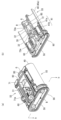
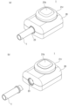
- FIG. 1(a) is a perspective view of the blood sampling device of the present disclosure viewed from above
- FIG. 1(b) is a perspective view of the blood sampling device of the present disclosure viewed from below
- FIG. 2(a) is a perspective view of the inside of the blood sampling device of the present disclosure
- FIG. 2(b) is a cross-sectional view taken along line bb in FIG. 2(a).
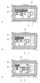
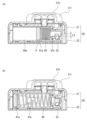
- FIG. 3(a) is a cross-sectional view taken along line ii in FIG. 1(a)
- FIG. 3(b) is a cross-sectional view taken along line ii in FIG. 1(a) when the button is pressed down.
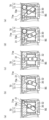
- FIGS. 4(a) to 4(c) are explanatory diagrams illustrating the operation of the slide member in the blade of the first embodiment.
- FIGS. 5A to 5E are explanatory diagrams illustrating the operation of the blade of the first embodiment.
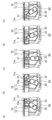
- FIGS. 6(a) to 6(c) are explanatory diagrams illustrating the operation of the slide member in the blade of the second embodiment.
- FIGS. 7A to 7E are explanatory diagrams illustrating the operation of the blade of the second embodiment.
- 8(a) is a cross-sectional view taken along line ii-ii in FIG. 1(a)
- FIG. 8(b) is a cross-sectional view taken along line ii-ii in FIG. 1(a) when the button is pressed down.
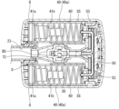
- FIG. 9 is an explanatory diagram illustrating the operation of the negative pressure generating cylinder.
- FIG. 10 is a perspective view of the trigger member.
- FIGS. 11A and 11B are explanatory diagrams illustrating how the skin is torn during blood collection.
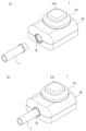
- FIG. 12(a) is an explanatory diagram illustrating the state before the storage container is attached to the blood collection device of the present disclosure
- FIG. 12(b) is an explanatory diagram illustrating the state after the storage container is attached to the blood collection device of the present disclosure. It is an explanatory diagram to explain.
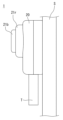
- FIG. 13 is an explanatory diagram illustrating a state in which the blood sampling device of the present disclosure is attached to the skin.
- FIG. 14 is an explanatory diagram illustrating how blood is collected by the blood collection device of the present disclosure.
- FIG. 15(a) is an explanatory diagram illustrating a state in which blood is collected in the storage container
- FIG. 15(b) is an explanatory diagram illustrating a state in which the storage container
- Up-down direction and “left-right direction” used directly or indirectly in this specification correspond to the up-down direction and the left-right direction in the drawings, respectively.
- the same reference numerals or symbols indicate the same members or parts or the same meanings.
- the downward direction in the vertical direction corresponds to the "downward direction”
- the opposite direction can be considered to correspond to the "upward direction.”
- terms indicating relationships between elements for example, “parallel”, “perpendicular”, etc.) and terms indicating the shape of elements do not only mean literal and strict aspects, but also substantially It also means a range that is technically equivalent, for example, a range that includes a difference of several percent.
- terms such as “provided” and “arranged” and derivative terms thereof are not limited to direct embodiments, but also refer to embodiments in which other elements such as intervening elements are present, unless explicitly stated otherwise. It may be.
- a “blood sampling device” in the present disclosure refers to a device for collecting blood from a subject in a broad sense, and in a narrow sense refers to a device that also includes a flow path that guides the collected blood to a storage container.
- the storage container that stores the collected blood may be built into the blood collection device, or may be externally attachable to the blood collection device.
- the blood sampling device of the present disclosure may include a storage container as a "blood sampling and storage device.”
- a blood sampling device 1 includes a housing 20, a blade 30, a negative pressure generating cylinder 40, and a trigger member 50. Each configuration will be described in detail below with reference to the drawings.
- the housing 20 accommodates each component of the blood collection device 1.
- the illustrated housing may have an overall square shape and may be made of a resin material (eg, plastic).
- the housing 20 may include, for example, a first body 21 and a second body 22 that are connectable to each other. That is, a single housing 20 can be constructed from the first body 21 and the second body 22.
- the first main body 21 may include a button 21b that is pressed when the subject starts blood collection, and a raised portion 21r that provides a space to accommodate the pressed button 21b.
- the button 21b may have a rectangular shape with rounded corners in plan view.
- the raised portion 21r may also have a rectangular shape with rounded corners in plan view.
- the second main body 22 may include a facing surface that faces the subject's skin.
- An adhesive member 22a may be provided on the facing surface.
- the adhesive member 22a may be of any material as long as it can adhere to the subject's skin, but it is preferably hypoallergenic and skin-friendly. By adhering the subject's skin and the blood collection device using the adhesive member 22a, blood can be appropriately collected.
- An opening 22h for allowing the blade 30 to protrude from the housing 20 may be provided on the facing surface.
- the opening 22h allows the blade 30 to protrude from the housing 20 to cut the subject's skin and collect blood.
- the side surface of the housing 20, which interconnects the first body 21 and the second body 22, may be provided with a mounting portion for attaching a storage container T (see FIG. 15) for storing collected blood.
- a storage container T (see FIG. 15) for storing collected blood.
- an opening 23 communicating with the flow path R (see FIG. 2(b)) through which the collected blood is guided may be provided.
- the storage container T may be freely attached to the opening 23.
- a gasket G may be provided near the opening 23 to bring the storage container T into close contact.
- the gasket G may be made of an elastically deformable resin material. If the gasket G is provided near the opening 23, leakage of blood can be prevented when the collected blood is stored in the storage container T.
- the attachment portion (opening 23) is preferably placed on the side of the housing 20 in the direction of gravity when the blood sampling device 1 is adhered to the skin (see also FIG. 13 as appropriate). In other words, it is preferable to move the plunger 41 in the negative pressure generating cylinder 40 described later. With this arrangement, the collected blood can be guided to the storage container T by its own weight.
- the inside of the housing 20 may include at least a blade space BS for accommodating the blade 30 and a cylinder space SS for accommodating the negative pressure generating cylinder 40 (see FIGS. 2(a) and 2(b)).
- the blade space BS may be provided in the central portion of the housing 20. Further, the blade space BS may communicate with the opening 22h in the facing surface described above. Furthermore, the blade space BS may communicate with the above-mentioned attachment portion (opening 23).
- negative pressure may be generated in the blade space BS by the negative pressure generating cylinder 40. That is, the blade space BS may act to draw in the collected blood by generating negative pressure. According to this aspect, blood can be appropriately collected by generating negative pressure.
- the periphery of the blade space BS may be sealed with an airtight maintenance member 90.
- the airtight maintenance member 90 may be made of an elastically deformable resin material.
- the airtight maintenance member 90 may be arranged above the blade space BS, as shown in FIG. 2(a).
- the airtight maintenance member 90 may also be arranged on the side surface of the blade space BS (for example, on the side surface on which the trigger member 50 is disposed). In this manner, the airtightness of the blade space BS can be improved by arranging the airtightness maintaining member 90 around the blade space BS and sealing it via the airtightness maintaining member 90.
- the cylinder space SS may be arranged on both sides of the blade space BS. That is, the cylinder spaces SS may form a pair.
- the cylinder space SS may communicate with the blade space BS on the side where the trigger member 50 is arranged. Therefore, when a negative pressure is generated in the cylinder space SS due to the operation of the negative pressure generating cylinder 40, a negative pressure can be generated in the blade space BS through the communication (as appropriate, see FIG. 9).
- the cylinder space SS may have a cylindrical shape corresponding to the cylindrical negative pressure generating cylinder 40 in order to accommodate the cylindrical negative pressure generating cylinder 40 described later. Moreover, it is preferable that the cylinder space SS extends along a direction perpendicular to the direction of gravity when the blood sampling device 1 is adhered to the skin. In other words, it is preferable that the cylinder space SS extends in the direction in which the collected blood is guided to the storage container T. Moreover, when specifying the cylinder space SS from another viewpoint, it is preferable that the cylinder space SS extends in the biasing direction of a compression coil spring 60 that moves a plunger 41 in a negative pressure generating cylinder 40, which will be described later.
- the negative pressure generation cylinder 40 is described as having a cylindrical shape in this specification, it is not limited to this shape, and may be columnar, for example.
- the blade 30 may include a metal blade that cuts the skin and a resin blade holder that holds the blade.
- the resin blade holding member may be made of the same resin material as the housing 20, or may be made of a different material.
- the blade 30 protrudes from the housing 20 and is movable to cut the skin in one direction during blood collection.
- a preferred embodiment of the blade 30 may be a configuration in which it engages with a movable body 70 (slider member 71 and guide member 72), which will be described later.
- a preferred aspect of the blade 30 includes an end portion 31 having an engaging protrusion that engages with a slider member 71 to be described later, and a shaft portion 32 that acts as a rotating shaft of the blade 30 and engages with a guide member 72. You can prepare.
- the shaft portion 32 acts as a rotation center of the blade 30, it may be configured to be displaced along a guide groove 72m of a guide member 72, which will be described later. Note that the displacement may specifically be a vertical displacement.
- the end portion 31 may extend from the blade 30 (more specifically, the end of the blade holding portion) along the biasing direction of the compression coil spring 60 used to move the slider member 71 (see FIG. a)). Further, the end portion 31 may have a cylindrical shape in order to cause the blade 30 to rotate. Note that the shape of the end portion 31 is not limited to a cylindrical shape as long as the blade 30 can be rotated smoothly.
- the shaft portion 32 may extend from the blade 30 (more specifically, from the side surface of the blade holding portion) along the biasing direction of the compression coil spring 60 used to move the slider member 71. Moreover, the shape of the shaft portion 32 may be cylindrical and protrude from the side surface of the blade holding portion. In other words, it may be a protrusion that becomes an axis of rotation. Note that the shape of the shaft portion 32 is not limited to a cylindrical shape as long as it can be smoothly rotated.
- the direction in which the skin is cut may be perpendicular to the direction of gravity (hereinafter also referred to as the "transverse direction") when the blood collection device is adhered to the skin (see FIGS. 4 and 5).
- the direction in which the skin is cut may be the direction of gravity (hereinafter also referred to as the "vertical cutting direction”) when the blood collection device is adhered to the skin (see FIGS. 6 and 7).
- the blade of the first embodiment and the blade of the second embodiment will be explained in order.
- a compression coil spring 60 that is compressed in advance may be used (see FIGS. 4(a) to 4(c)). That is, before blood collection, the compression coil spring 60 may be compressed toward the trigger member 50 arrangement side. In other words, the compression coil spring 60 may be compressed along the extending direction of the cylinder space SS. By releasing the compression of the compression coil spring 60, the blade 30 can be moved.
- the biasing direction of the compression coil spring 60 may be perpendicular to the direction in which the housing faces the skin. In other words, the direction may be parallel to the skin surface.
- the movement of the blade 30 may be brought about by a movable body 70 that rotates the blade 30 by a biasing force provided by a compression coil spring 60.
- the blade 30 may rotate to cut the skin in a predetermined direction (in the first embodiment, the transverse direction).
- the movable body 70 may be made of a resin material (for example, plastic) like the housing 20, or may be made of other materials.
- the movable body 70 includes a slider member 71 that holds the end portion 31 and is movable by the biasing force of the compression coil spring 60, and a guide member 72 formed with a guide groove 72m that accommodates the shaft portion 32 that rotates the blade. (See Figures 3 to 5). By moving the slider member 71 and the guide member 72, the blade 30 may cut the skin in a predetermined direction.
- the slider member 71 and guide member 72 will be described in detail below.
- the slider member 71 is a substantially rectangular plate-like member in a plan view, and includes a housing part that houses the compression coil spring 60 at a corner, a groove 71m formed on a diagonal line for sliding the end part 31, and a trigger.
- An engaging portion with which the member 50 (blade locking piece 52) engages may be provided.
- "on the diagonal” in this specification may be a direction forming an angle with respect to the extending direction of the negative pressure generating cylinder 40.
- “on the diagonal” in this specification may be a direction that forms an angle with respect to the compression direction of the compression coil spring 60 that moves the slider member 71.
- the specific aspect of the "direction forming the angle” is an angle at which the end portion 31 can be appropriately slid, and may be an acute angle, for example.
- the groove 71m may be in the form of a through groove. Further, as a preferred embodiment of the groove 71m, an eaves may be provided inside the groove 71m in order to make the end portion 31 slide in contact with the end portion 31. That is, the end portion 31 may be slidably movable while being held by the eaves of the through groove.
- the guide member 72 may be arranged below the slider member 71.
- the guide member 72 itself may be fixed within the blade space BS. That is, the guide member 72 does not need to move within the blade space BS.
- the shaft portion 32 of the blade may be accommodated in the guide groove 72m.
- the guide groove 72m may be provided parallel to the direction in which the housing 20 faces the skin. In other words, the guide groove 72m may be provided along the height direction of the housing 20. By forming the guide groove 72m in this manner, the blade 30 can be moved toward the skin.
- the slider member 71 Before blood collection, the slider member 71 is locked by the trigger member 50 (blade locking piece 52). Further, the compression coil spring 60 is in a compressed state on the trigger member 50 side. In this state, when the trigger member 50 (blade locking piece 52) is unlocked, the slider member 71 is moved away from the trigger member 50 (from the top to the bottom in the drawing) by the urging force provided by the compression coil spring 60. ) Slide to move. At this time, the end portion 31 moves from the right side to the left side in the drawing along the diagonal groove 71m (FIGS. 4(a) to 4(c)).
- the shaft portion 32 of the blade accommodated in the guide groove 72m moves as the slider member 71 slides. Specifically, it moves up and down in the vertical direction.
- the blade 30 is housed in the housing 20 when the slider member 71 is locked to the trigger member 50 (blade locking piece 52).
- the shaft portion 32 of the blade moves downward along the guide groove 72m as the slider member 71 slides (FIG. 5(b)). .
- the shaft portion 32 of the blade 30 moves to the lowest position of the guide groove 72m, and the blade 30 protrudes the most from the housing 20.
- the shaft portion 32 of the blade moves upward along the guide groove 72m, and the blade 30 is housed in the housing 20 (FIG. 5(d)).
- the compression coil spring 60 is fully extended, the sliding movement of the slider member 71 stops, and the blade finishes cutting (FIG. 5(e)).
- the blood collection device of the present disclosure may be a one-time use device. In other words, it may be a single-use type device.
- the blade 30 is moved to rotate around the shaft portion 32, and as the blade 30 rotates around the shaft, the skin is torn in a predetermined direction (in the first embodiment, the transverse direction).
- the blade shown in FIGS. 6 and 7 may be used as an aspect of the blade that cuts the skin in a direction different from that of the blade of the first embodiment. That is, by rotating the blade 30, the skin may be cut in the longitudinal cutting direction.
- the movable body 70 of the second embodiment will be described, but explanations that overlap with those of the first embodiment will be omitted as appropriate.
- the slider member 71 is a generally rectangular plate-like member in a plan view, and includes a housing portion that stores the compression coil spring 60 at a corner portion, a holding portion 71h that holds the end portion 31, and an engagement portion with which the trigger member 50 engages. It may include a joint and.
- the holding portion 71h may have a shape that matches the shape of the end portion 31 so that the cylindrical end portion 31 fits therein, and specifically, it may be in the form of a through hole. Furthermore, as a preferable aspect of the holding part 71h, an eaves for holding the end part 31 may be provided inside the holding part 71h. That is, the end portion 31b may be held inside the holding portion 71h by the eaves.
- the guide member 72 may be arranged below the slider member 71.
- the guide member 72 itself may be fixed within the blade space BS. That is, the guide member 72 does not need to move within the blade space BS.
- the shaft portion 32 of the blade may be accommodated in the guide groove 72m.
- the guide groove 72m may be provided parallel to the direction in which the housing 20 faces the skin. In other words, the guide groove 72m may be provided along the height direction of the housing. By forming the guide groove 72m in this manner, the blade 30 can be moved toward the skin.
- the slider member 71 Before blood collection, the slider member 71 is locked by the trigger member 50 (blade locking piece 52). Further, the compression coil spring 60 is in a compressed state on the trigger member 50 side. In this state, when the trigger member 50 (blade locking piece 52) is unlocked from the slider member 71, the slider member 71 is moved away from the trigger member 50 by the urging force provided by the compression coil spring 60 (from the top of the drawing). slide downward). At this time, the end portion 31 moves from the upper side of the drawing toward the lower side of the drawing in the illustrated example as the slider member 71 slides (see FIGS. 6(a) to 6(c)). More specifically, the end portion 31 moves in the same direction as the biasing direction of the compression coil spring 60 as the slider member 71 slides.
- the shaft portion 32 of the blade accommodated in the guide groove 72m moves as the slider member 71 slides. Specifically, it moves up and down in the vertical direction.
- the blade 30 is housed in the housing 20 when the slider member 71 is locked to the trigger member 50 (blade locking piece 52).
- the shaft portion 32 of the blade 30 moves downward in the drawing along the guide groove 72m as the slider member 71 slides (see FIG. 7(b) )).
- the blood collection device of the present disclosure may be a one-time use device. In other words, it may be a single-use type device.
- the blade 30 is moved to rotate around the shaft portion 32, and as the blade 30 rotates around the shaft, the skin is torn in a predetermined direction (in the second embodiment, the vertical cutting direction).
- the negative pressure generating cylinder 40 generates negative pressure within the housing 20 by moving the plunger 41 during blood collection.
- a preferred embodiment of the negative pressure generating cylinder 40 includes a cylindrical cylinder body 40a extending along the movable direction of the plunger 41, and a plunger 41 that moves within the cylinder body 40a to cause a volume change. good.
- the plunger 41 may include a disk portion 41a having a diameter comparable to the inner diameter of the cylinder body 40a, and a shaft core 41b protruding from the disk portion 41a toward the trigger member 50.
- the disk portion 41a may be provided with a gasket G for tightly contacting the inner wall of the cylinder body 40a.
- the shaft core 41b may include an engagement groove for engaging with the trigger member 50 (plunger locking piece 53). Further, a compression coil spring 60 may be attached to the shaft core 41b.
- the negative pressure generating cylinder 40 may be moved using a compression coil spring 60 that is compressed in advance. That is, before blood collection, the compression coil spring 60 may be compressed toward the trigger member 50 arrangement side. By releasing the compression of the compression coil spring 60, the plunger 41 can be moved to cause a change in volume within the cylinder body 40a, thereby generating negative pressure.
- the biasing direction of the compression coil spring 60 may be perpendicular to the direction in which the housing faces the skin. In other words, the direction may be parallel to the skin surface.
- the plunger 41 is locked by the trigger member 50 (plunger locking piece 53) through the engagement groove. Further, the compression coil spring 60 is in a compressed state on the trigger member 50 side. In this state, when the trigger member 50 (plunger locking piece 53) is unlocked, the plunger 41 is moved in a direction away from the trigger member 50 by the urging force provided by the compression coil spring 60. More specifically, as the plunger 41 moves, the volume of the cylinder body 40a on the plunger 41 side gradually increases, and negative pressure is generated.
- negative pressure By generating negative pressure in the negative pressure generating cylinder 40, negative pressure can be generated in the blade space BS communicating with the cylinder space SS. Note that when the compression coil spring 60 is fully extended, the volume increase on the plunger 41 side in the cylinder body 40a ends, and the generation of negative pressure ends.
- trigger member 50 is locked to the plunger 41 and the blade 30 so as to restrict the movement of both the plunger 41 and the blade 30 before blood collection, and the locking of both the plunger and the blade is released during blood collection.
- This is a member that allows the blade 30 and plunger 41 to move.
- the material of the trigger member 50 may be the same resin material as the housing 20, or may be a different material.
- Preferred embodiments of the trigger member 50 include a contact portion 51 that contacts the button 21b of the housing, a blade locking piece 52 that locks the movement of the blade, and a plunger locking piece 53 that locks the movement of the plunger. may be provided.
- the contact portion 51 may be provided so that the housing 20 extends in the direction toward the skin.
- the contact portion 51 may be configured to be pushed downward as the button 21b of the housing is pressed.
- a spring B (FIG. 2(a)) may be provided that has a repulsive force against depression of the button 21b of the housing. Note that, considering that the blood sampling device of the present disclosure is a one-time use device, the button 21b does not need to be pressed again even if the spring B causes repulsion. That is, the button 21b may be accommodated in the raised portion 21r by pressing the button 21b.
- the blade locking piece 52 may be provided so as to protrude from the side surface of the contact portion 51 toward the blade 30. This blade locking piece 52 may be able to engage with the engaging portion of the slider member 71 described above. The blade locking piece 52 may be unlatched from the engagement portion of the slider member 71 by being pushed downward in conjunction with pressing down of the button 21b of the housing.
- the plunger locking piece 53 may be provided to extend toward each negative pressure generating cylinder 40. Specifically, each plunger locking piece 53 may be arranged on the same straight line. Specifying each plunger locking piece 53 from another perspective, in plan view, a straight line connecting the plunger locking pieces 53 may be perpendicular to the direction in which the blade locking piece 52 projects. Specifying each plunger locking piece 53 from yet another perspective, the straight line connecting the plunger locking pieces 53 may be perpendicular to the direction in which the housing 20 faces the skin.
- the length L1 (FIG. 3(b)) of the blade locking piece 52 may be shorter than the length L2 (FIG. 8(b)) of the plunger locking piece 53.
- the blade 30 is first unlatched and then the negative pressure generating cylinder 40 is unlatched, as shown in FIG. 11(a), when the blade 30 cuts the skin S, negative pressure is generated in the blade space BS. This prevents the skin S from entering the blade space BS. When the skin S does not enter the blade space BS, the depth at which the blade 30 enters the skin S can be maintained at a constant depth.
- the negative pressure generation cylinder 40 will generate negative pressure in the blade space BS, as shown in FIG.
- the blade 30 cuts the skin S while this occurs.
- the skin S is torn while it enters the blade space BS.
- the amount of skin S that enters the blade space BS differs from subject to subject. In this case, the depth at which the blade 30 penetrates into the skin S differs from subject to subject, and the cutting of the skin by the blade 30 is unstable.
- the length L1 (FIG. 3(b)) of the blade locking piece 52 is made shorter than the length L2 (FIG. 8(b)) of the plunger locking piece 53. Therefore, it is preferable to first unlock the blade 30 and then release the negative pressure generating cylinder 40.
- a storage container T for storing collected blood is prepared (FIG. 12(a)).
- the outer shape of the storage container T may be configured to fit into the mounting portion (opening 23) of the housing described above.
- the storage container T After preparing the storage container T, the storage container T is attached to the attachment part (opening 23) of the blood collection device 1 (FIG. 12(b)).
- the gasket G is provided in the attachment portion (opening 23), it is possible to attach the blood collection device 1 and the storage container T in close contact with each other.
- the blood collection device 1 After attaching the storage container T to the blood collection device 1, the blood collection device 1 is adhered to the skin (FIG. 13).
- the adhesive member 22a is provided on the facing surface of the blood sampling device 1 that faces the subject's skin, the subject's skin and the blood sampling device can be appropriately bonded.
- the opening 22h that communicates with the blade space BS is closed with the skin, so the blade space BS can also be sealed.
- the storage container T attached to the blood sampling device 1 it is preferable to bond the storage container T attached to the blood sampling device 1 so that it is on the side where gravity acts (lower side in the vertical direction).
- the button 21b provided on the housing 20 is pressed.
- the trigger member 50 is engaged with the plunger 41 and the blade 30 so as to restrict the movement of both the plunger 41 and the blade 30 before the button 21b is pressed.
- the button 21b By pressing the button 21b in this state, the trigger member 50 moves in the direction toward the skin S. Along with this, both the plunger 41 and the blade 30 are unlocked, allowing the blade 30 and the plunger 41 to move.
- the compression coil spring 60 is released and the slider member 71 slides. Then, as the slider member 71 slides, the shaft portion 32 of the blade moves along the guide groove 72m of the guide member 72, so that the blade 30 cuts the skin.
- the operation of the blade 30 is as described in detail in "-Description of the operation of the blade of the first embodiment" and “-Description of the operation of the blade of the second embodiment" above.
- the trigger member 50 first unlocks the blade 30 and then releases the negative pressure generating cylinder 40. As the trigger member 50 unlocks the blade 30 and the negative pressure generating cylinder in this way, the depth at which the blade 30 penetrates into the skin can be maintained at a constant depth.
- the collected blood travels through the flow path R in the housing 20 and is stored in the storage container T (see FIG. 14).
- the flow path R is preferably inclined with respect to the facing surface of the housing 20 facing the skin S. More specifically, it is preferable that the end of the flow path R on the storage container T side be inclined away from the facing surface. By slanting the flow path R in this manner, blood can be properly guided to the storage container T.
- the blood stored in the storage container T is made visible from the outside (FIG. 15(a)).
- the storage container T is made of a transparent material. According to such a configuration, it is possible to visually determine how much blood is stored in the storage container T.
- the storage container T is removed from the blood collection device 1 (FIG. 15(b)), and the storage container is transported to a testing institution.
- the trigger member 50 releases the locking of both the plunger 41 and the blade 30 and allows the blade 30 and the plunger 41 to move during blood sampling. There is no need to separately prepare trigger parts for the operation of the blade 30 and plunger 41. Therefore, blood can be appropriately collected with a simple structure.
- the embodiments disclosed herein are illustrative in all respects, and are not the basis for a limited interpretation. Therefore, the technical scope of the present disclosure should not be interpreted only by the embodiments described above, but should be defined based on the claims. Further, the technical scope of the present disclosure includes all changes within the meaning and scope equivalent to the claims.
- the shape and/or color scheme of the housing in the blood collection device or blood collection storage device may be changed depending on the blood collection application and/or customer.
- the shape of the housing may be changed to a rectangular and/or circular shape for each blood collection application and/or customer, and/or the color scheme of the button on the housing may be changed for each blood collection application and/or customer. Good too.
- a blood collection device comprising a flow path that guides collected blood to a storage container, housing and a blade that protrudes from the housing and is movable to cut the skin in one direction; a negative pressure generating cylinder that generates negative pressure within the housing by moving a plunger; a trigger member that is housed in the housing and is activated when blood collection is started; The trigger member is engaged with the plunger and the blade so as to restrict movement of both the plunger and the blade; A blood sampling device that allows movement of the blade and the plunger when both the plunger and the blade are unlocked.
- a blood sampling device wherein a pre-compressed coil spring is used to move the plunger and/or the blade.
- the blood sampling device is characterized in that the blade is moved by a movable body that rotates the blade around its axis by a biasing force generated from the compression coil spring.
- the movable body is a slider member that holds one end of the blade and is movable by the biasing force of the coil spring; a guide member formed with a guide groove for accommodating a shaft portion that rotates the blade;
- the guide groove of the guide member is provided parallel to a direction in which the housing faces the skin.
- the blood sampling device according to the fourth aspect or the fifth aspect, wherein the shaft portion is movable along the guide groove of the guide member.
- the slider member has grooves formed diagonally, A blood sampling device, wherein one end of the blade is movable along the diagonal groove.
- the blood sampling device is characterized in that the direction in which the blade cuts the skin is perpendicular to the direction of gravity when the blood sampling device is adhered to the skin.
- Ninth aspect The blood sampling device according to the fourth aspect, wherein one end of the blade moves in the same direction as the biasing direction of the coil spring as the slider member moves.
- the blood sampling device is characterized in that the direction in which the skin is cut by the blade is the direction of gravity when the blood sampling device is adhered to the skin.
- the blood sampling device wherein the biasing direction of the coil spring used to move the plunger and/or the blade is perpendicular to the direction in which the housing faces the skin.
- Twelfth aspect The blood sampling device according to any one of the first to eleventh aspects, wherein an adhesive member is provided on a surface of the housing that faces the skin.
- the trigger member unlocks the plunger after unlocking the blade.
- the trigger member is a blade locking piece that locks the movement of the blade;
- a plunger locking piece that locks the movement of the plunger,
- the length of the blade locking piece is shorter than the length of the plunger locking piece.
- the blood sampling device is characterized in that a space in the housing that accommodates the blade has a negative pressure generated by the negative pressure generating cylinder.
- Sixteenth aspect The blood sampling device according to any one of the first to fifteenth aspects, wherein at least the periphery of the space accommodating the blade is sealed by an airtight member.
- the blood sampling device according to any one of the first to sixteenth aspects, wherein the negative pressure generating cylinders are arranged on both sides of a space that accommodates the blade.
- the blood sampling device is characterized in that the flow path communicating with the attachment portion is inclined with respect to a surface of the housing facing the skin.
- a blood collection storage device comprising: a storage container located on the gravity direction side when the blood collection device is adhered to the skin, and stores blood collected by the blood collection device.
- the blood collection device and blood collection storage device of the present disclosure are used to collect blood from a subject or to store the collected blood.
Landscapes
- Health & Medical Sciences (AREA)
- Life Sciences & Earth Sciences (AREA)
- Medical Informatics (AREA)
- Molecular Biology (AREA)
- Hematology (AREA)
- Biophysics (AREA)
- Pathology (AREA)
- Engineering & Computer Science (AREA)
- Biomedical Technology (AREA)
- Heart & Thoracic Surgery (AREA)
- Veterinary Medicine (AREA)
- Physics & Mathematics (AREA)
- Surgery (AREA)
- Animal Behavior & Ethology (AREA)
- General Health & Medical Sciences (AREA)
- Public Health (AREA)
- Dermatology (AREA)
- Pain & Pain Management (AREA)
- Measurement Of The Respiration, Hearing Ability, Form, And Blood Characteristics Of Living Organisms (AREA)
- Surgical Instruments (AREA)
Priority Applications (5)
| Application Number | Priority Date | Filing Date | Title |
|---|---|---|---|
| KR1020257005535A KR20250056189A (ko) | 2022-08-24 | 2023-07-20 | 채혈 디바이스 및 채혈 저류 디바이스 |
| EP23857048.5A EP4578384A4 (en) | 2022-08-24 | 2023-07-20 | BLOOD COLLECTION DEVICE AND BLOOD COLLECTION AND STORAGE DEVICE |
| US19/105,285 US20260198819A1 (en) | 2022-08-24 | 2023-07-20 | Blood collection device and blood collection and storage device |
| JP2024542656A JPWO2024042932A1 (cg-RX-API-DMAC7.html) | 2022-08-24 | 2023-07-20 | |
| CN202380059916.1A CN119730791A (zh) | 2022-08-24 | 2023-07-20 | 采血装置及采血存积装置 |
Applications Claiming Priority (2)
| Application Number | Priority Date | Filing Date | Title |
|---|---|---|---|
| JP2022133104 | 2022-08-24 | ||
| JP2022-133104 | 2022-08-24 |
Publications (1)
| Publication Number | Publication Date |
|---|---|
| WO2024042932A1 true WO2024042932A1 (ja) | 2024-02-29 |
Family
ID=90013244
Family Applications (1)
| Application Number | Title | Priority Date | Filing Date |
|---|---|---|---|
| PCT/JP2023/026566 Ceased WO2024042932A1 (ja) | 2022-08-24 | 2023-07-20 | 採血デバイスおよび採血貯留デバイス |
Country Status (6)
| Country | Link |
|---|---|
| US (1) | US20260198819A1 (cg-RX-API-DMAC7.html) |
| EP (1) | EP4578384A4 (cg-RX-API-DMAC7.html) |
| JP (1) | JPWO2024042932A1 (cg-RX-API-DMAC7.html) |
| KR (1) | KR20250056189A (cg-RX-API-DMAC7.html) |
| CN (1) | CN119730791A (cg-RX-API-DMAC7.html) |
| WO (1) | WO2024042932A1 (cg-RX-API-DMAC7.html) |
Cited By (1)
| Publication number | Priority date | Publication date | Assignee | Title |
|---|---|---|---|---|
| WO2026025574A1 (zh) * | 2024-07-30 | 2026-02-05 | 重庆居测生命健康科技有限公司 | 一种血液采集装置及其使用方法 |
Citations (2)
| Publication number | Priority date | Publication date | Assignee | Title |
|---|---|---|---|---|
| DE2841174A1 (de) * | 1977-09-23 | 1979-04-05 | Peter Unger | Vorrichtung zum anbringen eines hauteinschnitts vorgegebener laenge und tiefe |
| JP2021522946A (ja) * | 2018-05-14 | 2021-09-02 | ループ メディカル エスアー | ユーザーの流体のサンプルを抽出および採取するためのサンプル採取デバイス、システム、および方法 |
Family Cites Families (5)
| Publication number | Priority date | Publication date | Assignee | Title |
|---|---|---|---|---|
| US20110009847A1 (en) | 2009-03-02 | 2011-01-13 | Seventh Sense Biosystems, Inc. | Systems and methods for creating and using suction blisters or other pooled regions of fluid within the skin |
| HK1258397A1 (zh) | 2015-09-09 | 2019-11-08 | Drawbridge Health, Inc. | 用於样品收集、稳定化和保存的系统、方法和装置 |
| CN114209315B (zh) | 2015-12-21 | 2024-10-15 | 塔索公司 | 用于流体收集中的致动和缩回的装置、系统和方法 |
| JP7554816B2 (ja) * | 2019-08-30 | 2024-09-20 | タッソ インコーポレイテッド | 体液収集装置及び関連方法 |
| US20230138274A1 (en) * | 2020-03-31 | 2023-05-04 | Preci Health Sa | Body Fluids Sampling Device and Method of using the Same |
-
2023
- 2023-07-20 JP JP2024542656A patent/JPWO2024042932A1/ja active Pending
- 2023-07-20 KR KR1020257005535A patent/KR20250056189A/ko active Pending
- 2023-07-20 WO PCT/JP2023/026566 patent/WO2024042932A1/ja not_active Ceased
- 2023-07-20 CN CN202380059916.1A patent/CN119730791A/zh active Pending
- 2023-07-20 EP EP23857048.5A patent/EP4578384A4/en active Pending
- 2023-07-20 US US19/105,285 patent/US20260198819A1/en active Pending
Patent Citations (2)
| Publication number | Priority date | Publication date | Assignee | Title |
|---|---|---|---|---|
| DE2841174A1 (de) * | 1977-09-23 | 1979-04-05 | Peter Unger | Vorrichtung zum anbringen eines hauteinschnitts vorgegebener laenge und tiefe |
| JP2021522946A (ja) * | 2018-05-14 | 2021-09-02 | ループ メディカル エスアー | ユーザーの流体のサンプルを抽出および採取するためのサンプル採取デバイス、システム、および方法 |
Non-Patent Citations (1)
| Title |
|---|
| See also references of EP4578384A4 |
Cited By (1)
| Publication number | Priority date | Publication date | Assignee | Title |
|---|---|---|---|---|
| WO2026025574A1 (zh) * | 2024-07-30 | 2026-02-05 | 重庆居测生命健康科技有限公司 | 一种血液采集装置及其使用方法 |
Also Published As
| Publication number | Publication date |
|---|---|
| JPWO2024042932A1 (cg-RX-API-DMAC7.html) | 2024-02-29 |
| CN119730791A (zh) | 2025-03-28 |
| EP4578384A4 (en) | 2026-08-12 |
| KR20250056189A (ko) | 2025-04-25 |
| US20260198819A1 (en) | 2026-07-16 |
| EP4578384A1 (en) | 2025-07-02 |
Similar Documents
| Publication | Publication Date | Title |
|---|---|---|
| US11510659B2 (en) | Bodily fluid collection devices and related methods | |
| JP6403349B2 (ja) | 変形可能流体容器を操作するためのシステム、方法、および装置 | |
| JP4359671B2 (ja) | 体液採取用具 | |
| CN112294298A (zh) | 生物传感器的植入装置及其植入方法 | |
| WO2021041881A1 (en) | Bodily fluid collection devices and related methods | |
| US11633136B2 (en) | Bodily fluid collection devices and related methods | |
| TWI356686B (en) | Procedure for the filling and the evacuation of a | |
| CN119730791A (zh) | 采血装置及采血存积装置 | |
| US9033949B2 (en) | Needle protection device | |
| CN219021301U (zh) | 带安全锁的活检针 | |
| JPWO2024042932A5 (cg-RX-API-DMAC7.html) | ||
| JP2009056740A (ja) | インク容器収容体、及び収容体製造方法 | |
| CN105172442B (zh) | 一种自动夹笔的削笔机 | |
| CN210214759U (zh) | 一种开瓶器 | |
| JP2018140461A (ja) | 手持ち工具のフック | |
| CN105407856A (zh) | 用于组合物质、特别用于重组注射溶液的装置 | |
| CN215270586U (zh) | 雾化芯及气溶胶产生装置 | |
| CN112998825A (zh) | 一种植发笔 | |
| CN217180079U (zh) | 液体吸取装置 | |
| CN216294261U (zh) | 一种具有防止内容物漏出功能的利器盒 | |
| JP4544894B2 (ja) | 記録テープカートリッジ | |
| CN212292102U (zh) | 一种烫金机侧规定位装置 | |
| CN110436049B (zh) | 一种水晶首饰的包装盒 | |
| CN217414092U (zh) | 一种雪茄剪 | |
| JP7566446B1 (ja) | 給排気装置 |
Legal Events
| Date | Code | Title | Description |
|---|---|---|---|
| 121 | Ep: the epo has been informed by wipo that ep was designated in this application |
Ref document number: 23857048 Country of ref document: EP Kind code of ref document: A1 |
|
| WWE | Wipo information: entry into national phase |
Ref document number: 2024542656 Country of ref document: JP Ref document number: 202380059916.1 Country of ref document: CN |
|
| WWE | Wipo information: entry into national phase |
Ref document number: 2023857048 Country of ref document: EP |
|
| NENP | Non-entry into the national phase |
Ref country code: DE |
|
| WWP | Wipo information: published in national office |
Ref document number: 202380059916.1 Country of ref document: CN |
|
| ENP | Entry into the national phase |
Ref document number: 2023857048 Country of ref document: EP Effective date: 20250324 |
|
| WWP | Wipo information: published in national office |
Ref document number: 1020257005535 Country of ref document: KR |
|
| WWP | Wipo information: published in national office |
Ref document number: 2023857048 Country of ref document: EP |