WO2024042725A1 - アクチュエータ - Google Patents
アクチュエータ Download PDFInfo
- Publication number
- WO2024042725A1 WO2024042725A1 PCT/JP2022/032275 JP2022032275W WO2024042725A1 WO 2024042725 A1 WO2024042725 A1 WO 2024042725A1 JP 2022032275 W JP2022032275 W JP 2022032275W WO 2024042725 A1 WO2024042725 A1 WO 2024042725A1
- Authority
- WO
- WIPO (PCT)
- Prior art keywords
- housing
- shaft
- rotating disk
- rotor core
- keyways
- Prior art date
- Legal status (The legal status is an assumption and is not a legal conclusion. Google has not performed a legal analysis and makes no representation as to the accuracy of the status listed.)
- Ceased
Links
Images





Classifications
-
- H—ELECTRICITY
- H02—GENERATION; CONVERSION OR DISTRIBUTION OF ELECTRIC POWER
- H02K—DYNAMO-ELECTRIC MACHINES
- H02K1/00—Details of the magnetic circuit
- H02K1/06—Details of the magnetic circuit characterised by the shape, form or construction
- H02K1/12—Stationary parts of the magnetic circuit
- H02K1/18—Means for mounting or fastening magnetic stationary parts on to, or to, the stator structures
- H02K1/185—Means for mounting or fastening magnetic stationary parts on to, or to, the stator structures to outer stators
-
- H—ELECTRICITY
- H02—GENERATION; CONVERSION OR DISTRIBUTION OF ELECTRIC POWER
- H02K—DYNAMO-ELECTRIC MACHINES
- H02K11/00—Structural association of dynamo-electric machines with electric components or with devices for shielding, monitoring or protection
- H02K11/20—Structural association of dynamo-electric machines with electric components or with devices for shielding, monitoring or protection for measuring, monitoring, testing, protecting or switching
- H02K11/21—Devices for sensing speed or position, or actuated thereby
-
- H—ELECTRICITY
- H02—GENERATION; CONVERSION OR DISTRIBUTION OF ELECTRIC POWER
- H02K—DYNAMO-ELECTRIC MACHINES
- H02K5/00—Casings; Enclosures; Supports
- H02K5/04—Casings or enclosures characterised by the shape, form or construction thereof
- H02K5/15—Mounting arrangements for bearing-shields or end plates
-
- H—ELECTRICITY
- H02—GENERATION; CONVERSION OR DISTRIBUTION OF ELECTRIC POWER
- H02K—DYNAMO-ELECTRIC MACHINES
- H02K7/00—Arrangements for handling mechanical energy structurally associated with dynamo-electric machines, e.g. structural association with mechanical driving motors or auxiliary dynamo-electric machines
- H02K7/003—Couplings; Details of shafts
-
- H—ELECTRICITY
- H02—GENERATION; CONVERSION OR DISTRIBUTION OF ELECTRIC POWER
- H02K—DYNAMO-ELECTRIC MACHINES
- H02K21/00—Synchronous motors having permanent magnets; Synchronous generators having permanent magnets
- H02K21/12—Synchronous motors having permanent magnets; Synchronous generators having permanent magnets with stationary armatures and rotating magnets
- H02K21/14—Synchronous motors having permanent magnets; Synchronous generators having permanent magnets with stationary armatures and rotating magnets with magnets rotating within the armatures
- H02K21/16—Synchronous motors having permanent magnets; Synchronous generators having permanent magnets with stationary armatures and rotating magnets with magnets rotating within the armatures having annular armature cores with salient poles
Definitions
- the present disclosure relates to an actuator.
- an actuator that includes an encoder and a motor, such as a servo motor, it is necessary to attach the rotary disk of the encoder to the hollow shaft of the motor (for example, Japanese Patent Application Laid-Open No. 2017-203645).
- the relative angle between the rotating disk and the motor rotor is determined by the positional relationship between the rotating disk and the hollow shaft.
- the housing of the stator of the motor and the stator core are generally cylindrical close fit, the relative angle between the housing and each phase of the coil wound around the stator core is not determined.
- the fixing part of the rotary disk of the encoder provided on the hollow shaft of the rotor and the rotor core mounted on the rotor core are common.
- the relative angle between the magnet and the magnetic pole is also not determined.
- a stator including a housing, a stator core fixed within the housing and having a plurality of coils wound thereon, the stator further comprising:
- the rotor includes rotors disposed facing each other, the rotor includes a rotor core forming a plurality of magnetic poles, and a shaft coupled to the rotor core, and further includes an encoder unit, the encoder unit comprising: It includes a rotating disk connected to the shaft, a detection section that detects rotation of the rotating disk, and a fixing section that is fixed to the housing, and further includes a rotating disk that is connected to the plurality of coils of the stator core and the housing.
- first structural part that determines a relative angle between the rotor core
- second structural part that determines a relative angle between the magnetic poles of the rotor core and a fixed reference portion of the rotating disk provided on the shaft, and the shaft and the rotating disk.
- fourth structure that defines and adjusts a relative angle between the housing and the sensing portion.
- FIG. 3 is an axial cross-sectional view of the actuator according to the first embodiment.
- FIG. 3 is a radial cross-sectional view of the housing.
- FIG. 3 is a radial cross-sectional view of the stator core.
- FIG. 3 is a perspective view showing a hollow shaft and a rotating disk.
- FIG. 7 is an axial cross-sectional view of the actuator for explaining a modification of the second structure.
- FIG. 2 is another axial cross-sectional view of the actuator shown in FIG. 1;
- FIG. 7 is an axial cross-sectional view of an actuator according to another embodiment.
- FIG. 3 is a front view of the encoder fixing section.
- FIG. 7 is a partial axial cross-sectional view of an actuator according to another embodiment.
- 7B is a radial cross-sectional view of the actuator shown in FIG. 7A;
- FIG. 7B is a radial cross-sectional view of the actuator shown in FIG. 7A;
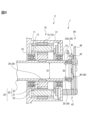
- FIG. 1 is an axial cross-sectional view of an actuator according to the first embodiment.
- the actuator 1 shown in FIG. 1 mainly includes a motor 5, such as a servo motor, consisting of a stator 10 and a rotor 20, and an encoder 40 connected to the motor 5.
- the encoder 40 including the rotating disk 41 is, for example, an incremental encoder, and outputs A-phase, B-phase, and Z-phase signals.
- Encoder 40 may be an optical encoder or a magnetic encoder.
- the stator 10 includes a stator core 11 disposed within a housing 12.
- Stator core 11 includes a plurality of coils 13 arranged around the central axis of motor 5 .
- the rotor 20 is rotatably arranged inside the stator core 11.
- the rotor 20 includes a rotor core 21 in which a plurality of magnets 22, for example, permanent magnets, are arranged on the outer peripheral surface, and a hollow shaft 23 that rotates integrally with the rotor core 21 on the central axis of the motor 5.
- the hollow shaft 23 is rotatably arranged in the housing 12 via bearings 51 and 52.
- FIG. 2A is a radial cross-sectional view of the housing.
- a pair of key grooves 16 are formed in the inner peripheral surface of the housing 12. These keyways 16 are formed at positions facing each other in the diametrical direction of the housing 12.
- the number of keyways 16 is one or more.
- a plurality of key grooves 16 may be formed at non-uniform intervals in the circumferential direction of the housing 12.
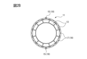
- FIG. 2B is a radial cross-sectional view of the stator core.
- a plurality of coils 13 are fixed to the inner peripheral surface of the stator core 11 at equal intervals.
- a plurality of grooves 17 are formed on the outer peripheral surface of the stator core 11 at positions corresponding to the center portions of the plurality of coils 13, respectively.
- parallel keys 15 extending parallel to the axial direction of the hollow shaft 23 are inserted into a pair of grooves 17 corresponding to the diameter direction of the stator core 11, respectively.
- the number of parallel keys 15 is preferably one or more, and in FIG. 2B, the parallel keys 15 are inserted into a pair of diametrically opposed grooves 17.
- the parallel key 15 may be inserted into another groove 17 located at a position corresponding to the key groove 16.
- the groove 17 may be formed at a position different from the central portion of the coil 13, for example, at a position corresponding to between two adjacent coils 13.
- the positions of one or more key grooves 16 formed in the housing 12 are known in advance, and the positional relationship between the groove 17 and the coil 13 is also known in advance. Therefore, by inserting one or more parallel keys 15 into the grooves 17 of the stator core 11 so as to engage such keyways 16, the relative angle between the plurality of coils 13 of the stator core 11 and the housing 12 can be adjusted. can be determined. Accordingly, one or more parallel keys 15, one or more keyways 16, one or more grooves 17 serve as a first structure 19 defining the relative angle between the coils 13 of the stator core 11 and the housing 12. fulfill the role of The same effect can also be obtained when the parallel key 15 and the groove 17 are integrated and a portion of the parallel key 15 protrudes from the groove 17 as a convex portion.
- the rotor core 21 and the hollow shaft 23 of the rotor 20 are separate members and are coupled to each other.
- the hollow shaft 23 and the rotor core 21 are integrally molded. That is, the hollow shaft 23 and the rotor core 21 are a single member.
- FIG. 3 is a perspective view showing the hollow shaft and the rotating disk.
- the hollow shaft 23 is provided with a fixed reference portion P for the rotating disk 41, such as a mark, on one part of the outer peripheral surface of the hollow shaft 23. It is formed in the part.
- the rotating disk 41 is attached to the hollow shaft 23 so that the rotating disk fixed reference portion P and the Z-phase slit S formed in advance in the rotating disk 41 correspond to each other.
- the rotating disk 41 is attached to the hollow shaft 23 as will be described later, so that the circumferential position of the rotating disk fixed reference portion P and the circumferential position of the Z-phase slit S coincide with each other.
- the hollow shaft 23 and the rotor core 21 are integrally molded, the relative angle between the magnetic pole of the rotor core 21 and the fixed reference portion P provided on the hollow shaft 23 is fixed and automatically determined. . Therefore, the hollow shaft 23 and the rotor core 21 that are integrally formed have a second structural part 29 that determines the positional relationship between the rotating disk fixed reference part P of the hollow shaft 23 and the magnetic pole of the magnet 22 mounted on the rotor core 21. fulfill its role as
- FIG. 4 is an axial cross-sectional view of the actuator for explaining a modification of the second structure.
- the rotor core 21 and the hollow shaft 23 are separate members.
- One or more grooves are formed in the inner peripheral surface of the rotor core 21 and the outer peripheral surface of the hollow shaft 23, respectively.
- One or more parallel keys 26 extending parallel to the axial direction of the hollow shaft 23 are fitted into the grooves of the rotor core 21 and the hollow shaft 23, so that the rotor core 21 and the hollow shaft 23 are coupled to each other. ing.
- the number and position of the parallel keys 26 are the same as those of the parallel keys 15 described above.
- the relative angle between the magnetic poles of the rotor core 21 and the fixed reference portion P provided on the hollow shaft 23 is fixed and automatically adjusted. Determined by Therefore, the groove formed on the inner circumferential surface of the rotor core 21, the groove formed on the outer circumferential surface of the hollow shaft 23, and the parallel key 26 serve as the second structural portion 29 described above. Note that the same effect can be obtained when the parallel key 26 and the corresponding groove are integrated and a portion of the parallel key 26 protrudes from the groove as a convex portion.
- the hollow shaft 23 includes an expanded portion 23A whose thickness expands toward the inside in the radial direction of the hollow shaft 23 between the rotating disk 41 and the motor 5.
- the expanded portion 23A is formed at one end of the hollow shaft 23 on the encoder 40 side. Due to the presence of such an expanded portion 23A, the inner diameter D1 of the hollow shaft 23 is larger than the inner diameter D2 of the expanded portion 23A.
- (D1-D2)/D1 is preferably between 0.1 and 0.2.
- the length and thickness of the expanded portion 23A in the axial direction of the hollow shaft 23 are large enough to receive a rotating disk fixing portion 35, which will be described later.
- the rotating disk 41 of the encoder 40 is fixed to the end surface of the extended portion 23A by the rotating disk fixing part 35.
- the rotating disk fixing portion 35 is formed on the end surface of the expanded portion 23A to correspond to a plurality of first screws 35 extending parallel to the axial direction of the hollow shaft 23 and the plurality of first screws 35. This is a combination of multiple holes.
- other types of rotating disk fixing portions 35 that can fix the rotating disk 41 to the extended portion 23A may be used.
- the rotating disk 41 of the encoder 40 can be easily connected to the end surface of the hollow shaft 23.
- the number of the plurality of first screws 35 and the number of the plurality of holes may be different, and the plurality of first screws 35 may not be arranged at equal intervals in the circumferential direction of the hollow shaft 23.
- FIG. 5 is another axial cross-sectional view of the actuator shown in FIG. 1.
- at least one filament C for example a cable, tube, etc. supplying power, signals or materials, passes through the actuator 1 through the interior space of the hollow shaft 23.
- At least one filament C is fixed near both ends of the actuator 1 by fixing parts (not shown in FIGS. 1 and 5).
- the thickness of the expanded portion 23A is sufficiently smaller than the inner diameter of the hollow shaft 23, so even if the expanded portion 23A is formed, there is no need to reduce the number of striatal bodies C. The slack of the striatum C may be maintained.
- the rotary disk 41 is fixed to the end surface of the extended portion 23A via the boss 25 by a plurality of first screws 35.
- the boss 25 is attached to the rotating disk 41 with adhesive or the like.
- the rotating disk 41 may be directly fixed to the end surface of the extended portion 23A.
- the rotary disk 41 of the encoder can be connected to the hollow shaft 23 more easily.
- the expanded portion 23A, the hole formed in the expanded portion 23A, and the first screw 35 serve as a third structure 39 that defines the relative angle between the hollow shaft 23 and the rotating disk 41. You can see that.
- FIG. 6 is an axial cross-sectional view of an actuator based on another embodiment.
- the actuator 1a in another embodiment has an expanded portion 23B whose thickness expands toward the outside in the radial direction of the hollow shaft 23 between the rotating disk 41 and the motor 5 instead of the expanded portion 23A.
- the inner diameter D1 of the hollow shaft 23 is equal to the inner diameter D2' of the expanded portion 23B.
- the rotating disk 41 of the encoder 40 is fixed to the end surface of the expanded portion 23B by a plurality of first screws 35 extending parallel to the axial direction of the hollow shaft 23.
- the detection unit 42 provided on the substrate 49 of the encoder 40 detects the absolute position PA1 within one rotation of the hollow shaft 23 and the total number of rotations PB1 using a known method.
- the detected information is stored in memory (not shown), for example volatile memory.
- FIG. 7 is a front view of the encoder fixing part.
- a plurality of elongated holes 46 are formed in the substrate 49 of the encoder fixing portion 43 of the encoder 40.
- a portion of each elongated hole 46 extending in the circumferential direction of the hollow shaft 23 is longer than a portion extending in the radial direction of the hollow shaft 23.
- Typical slots 46 are oblong or oval, but other shapes are possible.
- a plurality of second screws 45 are inserted into a plurality of long holes 46 in the substrate 49 and fixed to the housing 12.
- holes for a plurality of second screws 45 are formed in the housing 12 .
- the second screw 45 preferably extends parallel to the axial direction of the hollow shaft 23. Since the elongated hole 46 is not circular, the position of the encoder fixing portion 43 can be finely adjusted in the circumferential direction within the range of the circumferential length of the elongated hole 46 after the second screw 45 is screwed.
- the detection section 42 Since the detection section 42 is located at a predetermined position relative to the fixed section 43 of the encoder 40, the detection section 42 can be placed at a desired position relative to the housing 12. Therefore, the plurality of second screws 45 and elongated holes 46, as well as the holes in the housing 12, define the relative angle between the housing 12 and the detection section 42 and serve as the fourth structure section 48 that adjusts the relative angle. Fulfill.
- the fourth structure part 48 can leave room for adjusting the position of the detection part 42 in the rotational direction after the encoder 40 is attached.
- FIG. 8A is a partial axial cross-sectional view of an actuator according to another embodiment
- FIG. 8B is a radial cross-sectional view of the actuator shown in FIG. 8A
- the encoder 40 is not shown for the sake of brevity.
- a plurality of through holes are formed in the housing 12 of the actuator 1b shown in FIG. 8A in parallel to the axial direction of the hollow shaft 23.
- the stator core 11 has a flange 11 a that extends toward the outside in the radial direction of the hollow shaft 23 to the outer peripheral surface of the housing 12 .
- the flange 11a is configured to engage with the cutout portion of the housing 12.
- the flange 11a is sandwiched between the housing 12 from the upstream and downstream sides of the hollow shaft 23 in the axial direction.
- a plurality of through holes corresponding to the through holes of the housing 12 are also formed in the flange 11a of the stator core 11.
- the plurality of through holes in the flange 11a communicate with the plurality of through holes in the housing 12, respectively.
- the tie rod TL is positioned in each through hole of the flange 11a.
- the length of the tie rod TL is longer than the length of the flange 11a in the axial direction of the hollow shaft 23 and shorter than the length of the housing 12 in the axial direction of the hollow shaft 23. Therefore, both ends of each tie rod TL do not reach both ends of the housing 12 in the axial direction of the hollow shaft 23.
- the plurality of tie rods TL are arranged at equal intervals in the circumferential direction of the hollow shaft 23.
- a plurality of tie rods TL may be arranged at irregular intervals in the circumferential direction of the hollow shaft 23.
- a plurality of tie bolts TB are inserted into the aforementioned through holes from both ends of the housing 12 in the axial direction of the hollow shaft 23, and are coupled to each of the plurality of tie rods TL.
- female threads are preferably formed at both ends of each of the plurality of tie rods TL.
- the relative angle between the coil 13 of the stator core 11 and the housing 12 is fixedly determined.
- the flange 11a, the tie rod TL, and the tie bolt TB serve as the first structural portion 19.
- the tie rod TL may not be present, and the tie bolt TB may be screwed into a thread formed in the through hole of the flange 11a and the inner surface of the through hole of the housing 12.
- a plurality of tie rods TL that are longer than the length of the housing 12 in the axial direction of the hollow shaft 23 and have male threads formed at both ends thereof may be used.
- a nut is screwed into the male threaded portions instead of the tie bolt TB.
- the plurality of tie rods TL may be eliminated and a plurality of bolts longer than the length of the housing 12 in the axial direction of the hollow shaft 23 may be used. Then, the above-mentioned bolts are screwed into female threads formed in advance in the through holes of the flange 11a and the through holes of the housing 12.
- the relative angle between the coil 13 of the stator core 11 and the housing 12 can be fixed in the same way as described above. Therefore, the aforementioned nuts and bolts also serve as the first structural part 19.
- the relative angle between the plurality of coils 13 of the stator core 11 and the housing 12 is determined by the first structure part 19, and the magnetic poles of the rotor core 21 and the rotating disk 41 provided on the shaft 23 are fixed.
- the relative angle between the reference part is determined by the second structure part 29
- the relative angle between the shaft 23 and the rotating disk 41 is determined by the third structure part 39
- the relative angle between the housing 12 and the detection part 42 is determined by the third structure part 39. is determined and adjusted by the fourth structure part 48. Therefore, the Z-phase angle of the encoder unit can be adjusted accurately.
- the stator includes a housing and a stator core fixed within the housing and around which a plurality of coils are wound.
- the rotor includes a rotor core forming a plurality of magnetic poles and a shaft coupled to the rotor core, and further includes an encoder unit.
- a rotating disk connected to the shaft, a detection section that detects rotation of the rotating disk, and a fixing section fixed to the housing, and further comprising: a rotating disk connected to the shaft; a first structure that determines a relative angle between the rotor core, a second structure that determines a relative angle between the magnetic poles of the rotor core, and a fixed reference portion of the rotating disk provided on the shaft;
- An actuator is provided, comprising a third structure that defines a relative angle between the housing and the sensing portion, and a fourth structure that defines and adjusts a relative angle between the housing and the sensing portion.
- the third structure includes a boss attached to the rotating disk or a plurality of first screws fixing the rotating disk and the shaft; a plurality of screw holes formed in the shaft that engage with first screws.
- the fourth structure section is inserted into a plurality of long holes formed in the fixing section of the encoder unit, and into the plurality of long holes, respectively. and a plurality of second screws.
- the first structure includes a plurality of keyways formed in the stator core and the housing, and each of the plurality of keyways. and a plurality of parallel keys engaged with the parallel keys.
- the first structure includes a plurality of keyways formed in one of the housing and the stator core, and a plurality of keyways formed in one of the housing and the stator core. and a plurality of protrusions provided on the other of the stator cores and engaged with each of the plurality of keyways.
- the first structure portion is provided on the stator core and engages with the housing, and is formed on the housing and the flange and communicates with each other. It includes a plurality of through holes and a plurality of tie bolts that are screwed into the plurality of through holes.
- the second structure includes a plurality of keyways formed in the rotor core and the shaft, and each of the plurality of keyways. and a plurality of parallel keys engaged with the parallel keys.
- the second structure includes a plurality of keyways formed in one of the rotor core and the shaft, and a plurality of keyways formed in one of the rotor core and the shaft. and a plurality of protrusions provided on the other one of the shafts and engaged with each of the plurality of keyways.
- the rotor core and the shaft are integrally formed in the second structure.
- the encoder is an optical encoder or a magnetic encoder.
- the Z-phase angle of the encoder unit can be adjusted accurately.
- the relative angle between the shaft and the rotating disk can be fixed.
- the relative angle between the housing and the detection section is determined, and the relative angle is adjusted after the encoder is attached.
- the relative angle between the plurality of coils of the stator core and the housing can be fixedly determined.
- the relative angle between the plurality of coils of the stator core and the housing can be fixedly determined.
- the relative angle between the plurality of coils of the stator core and the housing can be fixedly determined.
- the relative angle between the plurality of coils of the stator core and the housing can be fixedly determined.
- the angle between the magnetic poles of the rotor core and the shaft can be fixed. In an eighth aspect, the angle between the magnetic poles of the rotor core and the shaft can be fixed. In the ninth aspect, the second structure can be easily configured.
Landscapes
- Engineering & Computer Science (AREA)
- Power Engineering (AREA)
- Microelectronics & Electronic Packaging (AREA)
Priority Applications (5)
| Application Number | Priority Date | Filing Date | Title |
|---|---|---|---|
| JP2024542569A JPWO2024042725A1 (https=) | 2022-08-26 | 2022-08-26 | |
| DE112022007222.9T DE112022007222T5 (de) | 2022-08-26 | 2022-08-26 | Aktuator |
| PCT/JP2022/032275 WO2024042725A1 (ja) | 2022-08-26 | 2022-08-26 | アクチュエータ |
| CN202280099114.9A CN119698746A (zh) | 2022-08-26 | 2022-08-26 | 致动器 |
| TW112127937A TW202408762A (zh) | 2022-08-26 | 2023-07-26 | 致動器 |
Applications Claiming Priority (1)
| Application Number | Priority Date | Filing Date | Title |
|---|---|---|---|
| PCT/JP2022/032275 WO2024042725A1 (ja) | 2022-08-26 | 2022-08-26 | アクチュエータ |
Publications (1)
| Publication Number | Publication Date |
|---|---|
| WO2024042725A1 true WO2024042725A1 (ja) | 2024-02-29 |
Family
ID=90012863
Family Applications (1)
| Application Number | Title | Priority Date | Filing Date |
|---|---|---|---|
| PCT/JP2022/032275 Ceased WO2024042725A1 (ja) | 2022-08-26 | 2022-08-26 | アクチュエータ |
Country Status (5)
| Country | Link |
|---|---|
| JP (1) | JPWO2024042725A1 (https=) |
| CN (1) | CN119698746A (https=) |
| DE (1) | DE112022007222T5 (https=) |
| TW (1) | TW202408762A (https=) |
| WO (1) | WO2024042725A1 (https=) |
Citations (9)
| Publication number | Priority date | Publication date | Assignee | Title |
|---|---|---|---|---|
| JPH07107725A (ja) * | 1993-09-29 | 1995-04-21 | Canon Precision Inc | ブラシレスモータ |
| JPH08205437A (ja) * | 1995-01-23 | 1996-08-09 | Toyota Motor Corp | 同期電動機 |
| JPH1189122A (ja) * | 1997-09-05 | 1999-03-30 | Toyota Motor Corp | 磁石内包型交流電動機およびその設計方法 |
| JP2014073011A (ja) * | 2012-09-28 | 2014-04-21 | Aisin Aw Co Ltd | 回転電機用ステータ及び回転電機 |
| JP2015053822A (ja) * | 2013-09-09 | 2015-03-19 | トヨタ自動車株式会社 | ロータ、および、ロータの製造方法 |
| WO2018216200A1 (ja) * | 2017-05-26 | 2018-11-29 | 三菱電機株式会社 | 回転電機 |
| JP2019129649A (ja) * | 2018-01-25 | 2019-08-01 | ユニパルス株式会社 | トルク検出付きギアモータ |
| JP2019187180A (ja) * | 2018-04-16 | 2019-10-24 | 株式会社ジェイテクト | モータ |
| JP2020005442A (ja) * | 2018-06-29 | 2020-01-09 | 株式会社東芝 | 回転電機の回転子 |
-
2022
- 2022-08-26 DE DE112022007222.9T patent/DE112022007222T5/de active Pending
- 2022-08-26 CN CN202280099114.9A patent/CN119698746A/zh active Pending
- 2022-08-26 WO PCT/JP2022/032275 patent/WO2024042725A1/ja not_active Ceased
- 2022-08-26 JP JP2024542569A patent/JPWO2024042725A1/ja active Pending
-
2023
- 2023-07-26 TW TW112127937A patent/TW202408762A/zh unknown
Patent Citations (9)
| Publication number | Priority date | Publication date | Assignee | Title |
|---|---|---|---|---|
| JPH07107725A (ja) * | 1993-09-29 | 1995-04-21 | Canon Precision Inc | ブラシレスモータ |
| JPH08205437A (ja) * | 1995-01-23 | 1996-08-09 | Toyota Motor Corp | 同期電動機 |
| JPH1189122A (ja) * | 1997-09-05 | 1999-03-30 | Toyota Motor Corp | 磁石内包型交流電動機およびその設計方法 |
| JP2014073011A (ja) * | 2012-09-28 | 2014-04-21 | Aisin Aw Co Ltd | 回転電機用ステータ及び回転電機 |
| JP2015053822A (ja) * | 2013-09-09 | 2015-03-19 | トヨタ自動車株式会社 | ロータ、および、ロータの製造方法 |
| WO2018216200A1 (ja) * | 2017-05-26 | 2018-11-29 | 三菱電機株式会社 | 回転電機 |
| JP2019129649A (ja) * | 2018-01-25 | 2019-08-01 | ユニパルス株式会社 | トルク検出付きギアモータ |
| JP2019187180A (ja) * | 2018-04-16 | 2019-10-24 | 株式会社ジェイテクト | モータ |
| JP2020005442A (ja) * | 2018-06-29 | 2020-01-09 | 株式会社東芝 | 回転電機の回転子 |
Also Published As
| Publication number | Publication date |
|---|---|
| JPWO2024042725A1 (https=) | 2024-02-29 |
| DE112022007222T5 (de) | 2025-04-10 |
| CN119698746A (zh) | 2025-03-25 |
| TW202408762A (zh) | 2024-03-01 |
Similar Documents
| Publication | Publication Date | Title |
|---|---|---|
| JP5292530B2 (ja) | ブラシレスモータ | |
| JPH1155902A (ja) | センサ組み込みモータの構造 | |
| JP4734516B2 (ja) | Dcブラシレスモータ | |
| WO2017046953A1 (ja) | 永久磁石同期モータ、永久磁石同期モータの製造方法、および空気調和機 | |
| CN112787458B (zh) | 丝杠装置 | |
| KR20140040608A (ko) | 회전 전기 | |
| US11204261B2 (en) | Rotational position detection device | |
| WO2024042725A1 (ja) | アクチュエータ | |
| JP5946796B2 (ja) | 回転機械の回転を検出する回転検出器、および回転検出器を備えるシステム | |
| CN102200540A (zh) | 旋转主轴的检测模组 | |
| WO2024250331A1 (zh) | 行星滚柱丝杠直线执行器 | |
| US8770052B2 (en) | Linear actuator | |
| US6969936B2 (en) | Rotational position detecting sensor-equipped motor and biaxial motor | |
| JP2008228367A (ja) | ブラシレスモータ | |
| JP7849486B2 (ja) | アクチュエータ | |
| JP2006262603A (ja) | 回転電機 | |
| TWI487265B (zh) | Rotation spindle detection module | |
| WO2024166391A1 (ja) | アクチュエータ | |
| CN215934666U (zh) | 电机、旋转变压器安装结构及旋转变压器转子安装结构 | |
| JP7847109B2 (ja) | 物理量検出センサとこれを備えた回転体組立体 | |
| JP7135786B2 (ja) | 固定子、磁気軸受、回転機械 | |
| JP2021122171A (ja) | ステッピングモータ | |
| JP2004120933A (ja) | ブラシレスモータ | |
| CN204514270U (zh) | 双转子磁阻式角位传感器 | |
| US12235132B2 (en) | Rotation detection device |
Legal Events
| Date | Code | Title | Description |
|---|---|---|---|
| 121 | Ep: the epo has been informed by wipo that ep was designated in this application |
Ref document number: 22956551 Country of ref document: EP Kind code of ref document: A1 |
|
| ENP | Entry into the national phase |
Ref document number: 2024542569 Country of ref document: JP Kind code of ref document: A |
|
| WWE | Wipo information: entry into national phase |
Ref document number: 112022007222 Country of ref document: DE |
|
| WWE | Wipo information: entry into national phase |
Ref document number: 202280099114.9 Country of ref document: CN |
|
| WWP | Wipo information: published in national office |
Ref document number: 202280099114.9 Country of ref document: CN |
|
| WWP | Wipo information: published in national office |
Ref document number: 112022007222 Country of ref document: DE |
|
| 122 | Ep: pct application non-entry in european phase |
Ref document number: 22956551 Country of ref document: EP Kind code of ref document: A1 |