WO2024038682A1 - 無線伝達システム - Google Patents
無線伝達システム Download PDFInfo
- Publication number
- WO2024038682A1 WO2024038682A1 PCT/JP2023/023717 JP2023023717W WO2024038682A1 WO 2024038682 A1 WO2024038682 A1 WO 2024038682A1 JP 2023023717 W JP2023023717 W JP 2023023717W WO 2024038682 A1 WO2024038682 A1 WO 2024038682A1
- Authority
- WO
- WIPO (PCT)
- Prior art keywords
- electromagnetic wave
- transmission system
- wireless transmission
- reflective
- reflective panel
- Prior art date
- Legal status (The legal status is an assumption and is not a legal conclusion. Google has not performed a legal analysis and makes no representation as to the accuracy of the status listed.)
- Ceased
Links
Images








Classifications
-
- H—ELECTRICITY
- H01—ELECTRIC ELEMENTS
- H01Q—ANTENNAS, i.e. RADIO AERIALS
- H01Q15/00—Devices for reflection, refraction, diffraction or polarisation of waves radiated from an antenna, e.g. quasi-optical devices
- H01Q15/14—Reflecting surfaces; Equivalent structures
-
- H—ELECTRICITY
- H01—ELECTRIC ELEMENTS
- H01Q—ANTENNAS, i.e. RADIO AERIALS
- H01Q15/00—Devices for reflection, refraction, diffraction or polarisation of waves radiated from an antenna, e.g. quasi-optical devices
- H01Q15/14—Reflecting surfaces; Equivalent structures
- H01Q15/16—Reflecting surfaces; Equivalent structures curved in two dimensions [2D], e.g. paraboloidal
-
- H—ELECTRICITY
- H01—ELECTRIC ELEMENTS
- H01Q—ANTENNAS, i.e. RADIO AERIALS
- H01Q17/00—Devices for absorbing waves radiated from an antenna; Combinations of such devices with active antenna elements or systems
-
- H—ELECTRICITY
- H05—ELECTRIC TECHNIQUES NOT OTHERWISE PROVIDED FOR
- H05K—PRINTED CIRCUITS; CASINGS OR CONSTRUCTIONAL DETAILS OF ELECTRIC APPARATUS; MANUFACTURE OF ASSEMBLAGES OF ELECTRICAL COMPONENTS
- H05K9/00—Screening of apparatus or components against electric or magnetic fields
Definitions
- the present invention relates to a wireless transmission system.
- Wireless base stations are being introduced indoors and outdoors for the purpose of automating manufacturing processes and office work, remote control, control and management using AI (Artificial Intelligence), and realizing autonomous driving.
- Wireless base stations are being introduced indoors at factories, plants, offices, commercial facilities, etc., outdoors at highways, railroad tracks, etc., and even in situations both indoors and outdoors, such as medical sites and event venues.
- the 5th generation mobile communication standard (hereinafter referred to as "5G") provides a frequency band of 6 GHz or less called “sub-6" and a 28 GHz band classified as a millimeter wave band.
- the next-generation 6G mobile communications standard is expected to expand to sub-terahertz bands. By using such a high frequency band, the communication bandwidth can be greatly expanded, and a large amount of data can be communicated with low delay.
- a configuration has been proposed in which an electromagnetic reflection device is arranged along at least a portion of a manufacturing line (for example, see Patent Document 1).
- One object of the present invention is to provide a wireless transmission system that achieves both improvement of the radio wave propagation environment and suppression of radio waves spilling out of the required space.
- the wireless communication system includes: A base station that is installed outdoors or in an environment close to outdoors and communicates wirelessly in a predetermined frequency band of 1 GHz or more and 300 GHz or less; an electromagnetic wave reflecting device having a reflective panel that reflects electromagnetic waves in the predetermined frequency band and provided along a predetermined area within the communication area of the base station;
- the transmitting antenna of the base station forms a transmitting beam toward the predetermined area so that the output electromagnetic wave is incident at a position lower than the top height of the electromagnetic wave reflecting device,
- the reflective panel is located within a range of 5.0 m or more and 300.0 m or less from the transmitting antenna at the shortest distance, and reflects the electromagnetic waves in the predetermined frequency band within the predetermined area,
- the received power outside the predetermined area is lower than the median value of the received power within the predetermined area.
- a wireless transmission system is realized that improves the radio wave propagation environment and suppresses radio waves from ejecting outside the required space.
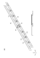
- FIG. 1 is a schematic diagram of a wireless transmission system according to an embodiment.
- FIG. 2 is a schematic diagram of an electromagnetic wave reflecting fence in which a plurality of electromagnetic wave reflecting devices are connected.
- FIG. 7 is a schematic diagram of a modified example of an electromagnetic wave reflecting device and an electromagnetic wave reflecting fence.
- 2A is a horizontal cross-sectional configuration example of the frame taken along line AA in FIG. 2A.
- FIG. FIG. 7 is a diagram showing another example of arrangement of an electromagnetic wave reflecting device and an electromagnetic wave reflecting fence.
- 3A is a horizontal cross-sectional configuration example of the frame taken along line BB in FIG. 3A.
- FIG. 3B is a top view of the coupling portion C in FIG. 3A.
- FIG. 3 is a diagram showing a model of a conductive layer used for evaluation.
- FIG. 3 is a diagram showing an analysis space.
- FIG. 2 is a schematic diagram of an a-b plane in an analysis space. It is a schematic diagram of the ac plane of analysis space.
- FIG. 2 is a top view of a simulation model of a wireless transmission system.
- FIG. 2 is a perspective view of a simulation model of a wireless transmission system.
- 12 is a diagram showing the material and coordinates of objects used in the models of FIGS. 10 and 11.
- FIG. 12 is a diagram showing the received power distribution of Example 7.
- FIG. 12 is a diagram showing the received power distribution of Example 8.
- FIG. 10 is a diagram showing the received power distribution of Example 9.
- FIG. 10 is a diagram showing the received power distribution of Example 10.
- FIG. 12 is a diagram showing the received power distribution of Example 11.
- FIG. 12 is a diagram showing the received power distribution of Example 12.
- Embodiments provide a wireless transmission system used outdoors or in a near-outdoor environment, and an electromagnetic wave reflecting panel used in this wireless transmission system.
- An environment close to the outdoors refers to spaces that connect indoors and outdoors, such as terraces, arcades, balconies, etc., or indoor spaces located near glass, plastic, etc. that transmit electromagnetic waves.
- it is necessary to both improve the radio wave propagation environment and prevent radio waves from leaking out to the outside.
- Electromagnetic wave reflection devices are effective in reducing dead zones and improving the radio wave propagation environment. Considering use outdoors or in an environment close to outdoors and prevention of radio waves from emitting, it is necessary to arrange the electromagnetic wave reflecting device in an optimal positional relationship with respect to the base station antenna. On the other hand, it is necessary to increase the mechanical strength and improve the weather resistance of reflective panels used in electromagnetic wave reflecting devices.
- the embodiment provides a wireless transmission system that satisfies these requirements.
- a wireless transmission system according to an embodiment, a reflective panel used in the wireless transmission system, and an electromagnetic wave reflecting device using the reflective panel will be described.
- the form shown below is an example for embodying the technical idea of the present invention, and is not intended to limit the present invention.
- the size, positional relationship, etc. of each member shown in each drawing may be exaggerated in order to facilitate understanding of the invention.
- the same name or code may be given to the same component or function, and redundant description may be omitted.
- FIG. 1 is a schematic diagram of a wireless transmission system 1 according to an embodiment.
- the wireless transmission system 1 is installed outdoors or in an environment close to the outdoors, and includes a base station 33 that communicates wirelessly at a frequency included in a predetermined frequency band of at least 1 GHz or more and 170 GHz or less, preferably 1 GHz or more and 300 GHz or less, and an electromagnetic wave reflecting device. 60 included.
- the electromagnetic wave reflection device 60 has a reflection panel that reflects electromagnetic waves at the frequency of the base station 33, and is provided in a predetermined area where installation is required within the communication area of the base station 33.
- FIG. 1 is a schematic diagram of a wireless transmission system 1 according to an embodiment.
- the wireless transmission system 1 is installed outdoors or in an environment close to the outdoors, and includes a base station 33 that communicates wirelessly at a frequency included in a predetermined frequency band of at least 1 GHz or more and 170 GHz or less, preferably 1 GHz or more and 300 GHz or less, and an electromagnetic wave reflecting device
- the wireless environment of a road 32 which is an area extending in a fixed direction within the communication area of the base station 33.
- the length direction of the road 32 is the X direction
- the width direction is the Y direction
- the direction perpendicular to the road surface is the Z direction.
- a large number of vehicles 31 travel on a road 32.
- the vehicle 31 may be a vehicle with an automatic driving function or a semi-automatic driving function, or may be a vehicle without an automatic driving function. In either case, the vehicle 31 itself has a wireless communication function, in addition to the mobile terminal held by the driver or passenger, and a large amount of data is transmitted and received between the vehicle 31 and the control/management system.
- a base station 33 is placed along the road 32 in order to realize wireless communication between a mobile object such as a vehicle 31 and the network.
- the base station 33 transmits and receives signals or data to and from the vehicle 31 at a predetermined frequency within a frequency band of 1 GHz or more and 170 GHz or less. Due to the topography of the road 32, the surrounding environment, and the presence of a large number of vehicles 31, it is difficult to directly deliver high-frequency radio waves with poor straightness from the base station 33 to each vehicle 31. Therefore, the electromagnetic wave reflecting device 60 is disposed on at least one side of the road 32 and along at least a portion of the road 32. Radio waves are a type of electromagnetic wave, and generally, electromagnetic waves with a frequency of 3 THz or less are called radio waves.
- the communication waves transmitted from the base station 33 are referred to as "radio waves,” and electromagnetic waves in general are referred to as “electromagnetic waves.”
- a plurality of electromagnetic wave reflecting devices 60 may be connected and installed on the shoulder of the road 32 as an electromagnetic wave reflecting fence.
- the top position of the electromagnetic wave reflecting device 60 is set depending on the environment in which the electromagnetic wave reflecting device 60 is installed, and may be located at a lower position than the transmitting antenna of the base station 33, or depending on the surrounding environment or situation. It may be located at the same height as the transmitting antenna or at a higher position. In either case, the electromagnetic waves output from the transmitting antenna of the base station 33 are incident on a position lower than the top end of the reflecting surface of the electromagnetic wave reflecting device 60.
- the incident electromagnetic wave is incident at a position lower than the top end of the reflective surface, it means that the incident electromagnetic wave is incident on the reflective surface in a manner that allows the reflected wave to reach the desired space with sufficient intensity, and the power is 1/1/2 of the peak.
- the base station 33 has a directional antenna that forms a beam toward the road.
- the electromagnetic wave reflection device 60 along at least one side of the road 32, radio waves from the base station 33 are efficiently concentrated on the road 32, and the radio waves from the base station 33 are efficiently concentrated on the road 32. suppresses radio waves emitted outside.
- the received power outside the road 32 is lower than the average value or median value of the received power on the road 32.
- both transmitting antennas and directional antennas may be simply referred to as "antennas.”
- the radio waves from the base station 33 can be reflected by the electromagnetic wave reflection device 60 and delivered to the vehicle 31.
- the shortest distance from the antenna of the base station 33 to the electromagnetic wave reflection device 60 is 5.0 m or more and 300.0 m or less, and the maximum gain of the base station 33 antenna is 5 dBi or more and 30 dBi or less. You can also do this.
- the shortest distance between the antenna of the base station 33 and the electromagnetic wave reflector 60 is less than 5.0 m, it will be difficult to efficiently deliver radio waves from the base station 33 to the vehicle 31 via the electromagnetic wave reflector 60. . If the shortest distance between the base station 33 and the electromagnetic wave reflector 60 is 300.0 m, it is recommended that the radio waves be delivered to the vehicle 31 via the electromagnetic wave reflector 60 from the viewpoint of the maximum gain of the antenna and the straightness of the radio waves. It becomes difficult.
- the size of the reflecting surface of the electromagnetic wave reflecting device 60 may be large enough to cover at least the area determined by the radius R of the first Fresnel zone.
- the radius R of the first Fresnel zone when the radio waves radiated from the antenna of the base station 33 and reflected by the electromagnetic wave reflection device 60 reach the vehicle 31 in the same phase is defined by the following equation.
- R [ ⁇ d1d2/(d1+d2)] 1/2
- ⁇ is the wavelength used
- d1 is the distance from the antenna of the base station 33 to the electromagnetic wave reflecting device 60
- d2 is the distance from the electromagnetic wave reflecting device 60 to the antenna of the vehicle 31.
- the electromagnetic wave The size of the reflecting surface of the reflecting device 60 only needs to be several tens of centimeters on one side.
- the width x length of the reflecting surface of the electromagnetic wave reflecting device 60 is approximately 2.0 m x 4.0 m. There may be.
- electromagnetic wave reflection is performed such that the received power on the back side of the reflective surface of the electromagnetic wave reflecting device 60, that is, in the area outside the road 32, is lower than the average value or median value of the received power on the road 32.
- Device 60 is placed along road 32.
- FIG. 2A is a schematic diagram of the electromagnetic wave reflecting fence 100A.
- the electromagnetic wave reflecting fence 100A includes electromagnetic wave reflecting devices 60A-1, 60A-2 having reflective panels 10A-1, 10A-2, and 10A-3 (hereinafter, may be collectively referred to as "reflecting panels 10A” as appropriate), and 60A-3 (hereinafter, may be collectively referred to as "electromagnetic wave reflecting device 60A" as appropriate) are connected by a frame 50A.
- the coordinate system in FIG. 2A is consistent with the coordinate system in FIG. 1, and the width or lateral direction of the reflective panel 10 is the X direction, the thickness direction is the Y direction, and the height direction is the Z direction.
- three electromagnetic wave reflecting devices 60A are connected to form an electromagnetic wave reflecting fence 100A, but the number of electromagnetic wave reflecting devices 60A to be connected is determined as appropriate depending on the environment in which they are installed.
- the reflective panel 10A used in the electromagnetic wave reflecting device 60A reflects electromagnetic waves of 1 GHz or more and 170 GHz or less, preferably 1 GHz or more and 100 GHz or less, and more preferably 1 GHz or more and 80 GHz or less.
- the reflective panel 10A has a layer containing a conductive film as a reflective film.
- the conductive film has a predetermined conductive pattern designed according to the desired reflection angle, frequency band, etc.
- the conductive pattern includes a picture such as a periodic pattern, a mesh pattern, a geometric pattern, etc., and may be formed of a transparent conductive film.
- the reflective panel 10A has a protective layer having an ultraviolet ray prevention function as the outermost layer.
- At least a portion of the reflective panel 10A may be a non-specular reflective surface with a different angle of incidence and reflection angle of electromagnetic waves.
- Non-specular reflective surfaces include diffuse surfaces, scattering surfaces, and metasurfaces that are artificial reflective surfaces designed to reflect radio waves in a desired direction. It may be desirable for the reflective panels 10A-1, 10A-2, and 10A-3 to be electrically connected to each other from the viewpoint of maintaining continuity of reflected potential, but if they include a metasurface, adjacent There may be no electrical connection between the reflective panels 10A. By holding adjacent reflective panels 10A with a frame 50A, an electromagnetic wave reflective fence 100A connected in the X direction is obtained.
- the electromagnetic wave reflecting device 60A may have legs 56 that support the frame 50A.
- the legs 56 may allow the electromagnetic wave reflecting device 60A or the electromagnetic wave reflecting fence 100A to stand on the road surface.
- the leg portions 56 may be configured to be fixed to the road surface with screws, screws, or the like.
- the electromagnetic wave reflecting device 60A or the electromagnetic wave reflecting fence 100A may be made to stand up on the road surface, and may also be movable by having parts such as casters.
- a top frame 57 that holds the upper end of the reflective panel 10 and a bottom frame 58 that holds the lower end may be used.
- the frame 50A, the top frame 57, and the bottom frame 58 constitute a frame that holds the entire circumference of the reflective panel 10A.
- the frame 50A may also be called a "side frame” due to its positional relationship with the top frame 57 and bottom frame 58.
- Providing the top frame 57 and the bottom frame 58 ensures mechanical strength and safety during transportation and assembly of the reflective panel 10.
- the top frame 57 may be configured to be able to connect another member such as another reflective panel or an electromagnetic wave absorption panel to the upper end of the reflective panel 10A. This increases the degree of freedom in size and function of the electromagnetic wave reflecting fence 100A.
- FIG. 2B is a schematic diagram of an electromagnetic wave reflecting fence 100B as a modified example.
- the electromagnetic wave reflection fence 100B includes electromagnetic wave reflection devices 60B-1, 60B-2 having reflection panels 10B-1, 10B-2, and 10B-3 (hereinafter, may be collectively referred to as “reflection panels 10B” as appropriate), and 60B-3 (hereinafter, may be collectively referred to as "electromagnetic wave reflecting device 60A" as appropriate) are connected by a frame 50B.
- Reflection panel 10B includes a curved surface at least in part. In this example, the reflective panel 10B is curved at the upper end side in the Z direction.
- the frame 50B has a curvature corresponding to the curvature of the reflective panel 10B.
- the radius of curvature of the reflective panel 10B is determined depending on the width of the road 32 to which the electromagnetic wave reflecting device 60B is applied, the surrounding conditions, the thickness of the reflective panel 10B, the height of the electromagnetic wave reflecting device 60B, and the like.
- the radius of curvature of the reflective panel 10B is set to 1500 mm or more and 2500 mm or less, preferably 2000 mm or more and 2500 mm or more.
- the reflective panel 10B may have a layer containing an ultraviolet inhibitor in the outermost layer.
- a configuration in which another flat reflective panel 10 or another member such as an electromagnetic wave absorption panel is connected to the top frame 57 at a predetermined inclination angle may be used.
- FIG. 2C shows an example of the structure of the frame 50.
- This configuration example corresponds to a cross-sectional configuration parallel to the XY plane of the frame 50A along line AA in FIG. 2A.
- the frame 50B in FIG. 2B has the same cross-sectional configuration as the frame 50A except that the upper portion is curved along the curve of the reflective panel 10B, and therefore will be collectively referred to as "frame 50" in the following description.
- the frame 50 has a conductive main body 500 and slits 51-1 and 51-2 formed on both sides of the main body 500 in the width direction.
- the edges of reflective panels 10-1 and 10-2 are inserted into slits 51-1 and 51-2, respectively, and held within space 52.
- the space 52 is not essential, by providing the space 52, the main body 500 of the frame 50 can be made lighter, and the holding angle of the reflective panel 10 can be made more flexible.
- Adjacent reflective panels 10-1 and 10-2 can be stably held by inserting reflective panels 10-1 and 10-2 into slits 51-1 and 51-2, respectively. Even when a part of the reflective panel 10B is curved as shown in FIG. 2B, the edge of the curved reflective panel 10B is inserted and held in the slit 51 of the curved frame.
- a portion of body 500 may be formed of a non-conductive material.
- a non-conductive cover 501 made of resin or the like may be provided on the outer surface of the main body 500, but when the cover 501 is provided, the cover 501 may be formed of a resin material with good weather resistance.
- FIG. 3A shows an example of the arrangement of electromagnetic wave reflecting devices 60C-1, 60C-2, and 60C-3 (hereinafter collectively referred to as "electromagnetic wave reflecting devices 60C") and an electromagnetic wave reflecting fence 100C.
- the electromagnetic wave reflecting device 60C can be placed in an appropriate orientation or direction depending on the geographical conditions of the installation location and the presence of a dead zone.
- the electromagnetic wave reflecting devices 60C-2 and 60C-3 are coupled in different directions in the XY plane.
- the reflection panel 10A of each electromagnetic wave reflection device 60C is held and coupled by a frame 550.
- the upper end and lower end of each reflective panel 10A may be held by a top frame 57 and a bottom frame 58, respectively.
- the height of the top of the reflective panel 10A of each electromagnetic wave reflecting device 60C is set according to the environment in which the electromagnetic wave reflecting device 60C is placed and the position of the transmitting antenna of the base station providing the communication area, and the height of the top of the reflecting panel 10A of each electromagnetic wave reflecting device 60C is set according to the When the beam is incident, the main lobe of the incident beam is reflected downward (in the -Z direction).
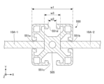
- FIG. 3B is a configuration example of a horizontal cross section of the frame 550 taken along line BB in FIG. 3A.
- This horizontal cross section shows the frame configuration in a plane parallel to the XY plane.
- the frame 550 has a main body 505 made of a conductor such as aluminum, and slits 551a, 551b, 551c, and 551d (hereinafter collectively referred to as "slits 551" as appropriate) formed in the main body 505.
- Reflective panels 10A-1 and 10A-2 are inserted and held in opposing slits 551a and 551b of frame 550, respectively.
- a portion of the main body 505 of the frame 550 is hollow to reduce weight, the frame 550 is not limited to the shape shown in FIG. 3B as long as it can hold at least two reflective panels 10A.
- Frame 550 having the horizontal cross-sectional shape of FIG. 3B may be formed, for example, by injection molding.
- the outer shape of the frame 550 in horizontal cross section is approximately square, and is processed into a shape that is approximately symmetrical with respect to the center of the main body 505.
- Frame 550 may be used in any orientation.
- the width w1, which corresponds to the length of one side of the horizontal cross section of the frame 550, is, for example, from 40 mm to 60 mm.
- the width w2 of the slits 551a to 551d is determined depending on the thickness of the reflective panel 10A used.
- the thickness w3 of the center portion of the main body 505 is set in the range of 15 mm to 35 mm depending on the strength required for the frame 550.
- the outer surface of the frame 550 may be covered with an insulating cover made of resin or the like.
- FIG. 3C is a top view of the coupling part C in FIG. 3A.
- Reflective panels 10A-2 and 10A-3 are held and coupled to adjacent slits 551a and 551c of frame 550. By selecting an appropriate slit 551, the reflective panel 10A can be coupled in two directions. As shown in FIG. 3A, reflective panels 10A-1 and 10A-2 may be coupled in the +X direction, and reflective panels 10A-2 and 10A-3 may be coupled in the -Y direction. Another reflective panel 10A may be coupled to the reflective panel 10A-3 in the -X direction. Thereby, the predetermined space can be surrounded and radio waves can be effectively suppressed from flying out.
- FIG. 4 shows an example of coupling the electromagnetic wave reflecting fence 300.
- the electromagnetic wave reflective fence 300 includes two sets of electromagnetic wave reflective fences 100-1 and 100-2 installed in parallel or non-parallel, and a ceiling panel 110 that covers the upper ends of the electromagnetic wave reflective fences 100-1 and 100-2.
- the planar shape of the ceiling panel 110 is determined depending on the direction in which the electromagnetic wave reflecting fences 100-1 and 100-2 are arranged.
- the ceiling panel 110 like the reflective panel 10A used in the electromagnetic wave reflective fences 100-1 and 100-2, is a reflective surface that reflects radio waves from a base station (for example, a predetermined band in the range from 1 GHz to 170 GHz). has.
- the reflective surface may be a specular reflective surface, or at least a portion thereof may include a non-specular reflective surface.
- the outermost layer of the ceiling panel 110, in particular the outwardly facing surface, may be provided with a protective layer having an anti-ultraviolet function.
- a flat rectangular ceiling panel 110 is used to cover the area between electromagnetic wave reflecting fences 100-1 and 100-2 facing each other at a predetermined distance.
- the frame 550 shown in FIGS. 3B and 3C may be used as the top frame that holds the upper end of the reflective panel 10A.
- the slit 551a of the frame 550 may hold the upper end of the reflective panel 10A, and the adjacent slit 551d may hold the edge of the ceiling panel 110.
- the ceiling panel 110 is not limited to a flat panel, but may have an arched curved surface.
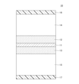
- FIG. 5 shows an example of the layer structure of the reflective panel 10.
- the layer structure in FIG. 5 is the structure in the thickness (Y) direction of the reflective panel 10.
- the reflective panel 10 includes a conductive layer 11, a dielectric layer 14 or 15 bonded to at least one surface of the conductive layer 11 via an adhesive layer 12 or 13, and a protection provided on the surface of the dielectric layer 14 or 15.
- Layer 16 or 17 included.
- conductive layer 11 is sandwiched between dielectric layers 14 and 15 via adhesive layers 12 and 13, and protective layers 16 and 17 are provided on both surfaces of dielectric layers 14 and 15.
- the protective layers 16 and 17 have an ultraviolet protection function.
- a protective layer may be provided only on the outer surface of the curved surface of the reflective panel 10B.
- the reflecting panel 10 When the electromagnetic wave reflecting device 60 is used outdoors or in an indoor facility close to an outdoor environment, it is desirable that the reflecting panel 10 has weather resistance.
- the reflective panel 10 of the embodiment has mechanical strength and weather resistance that can withstand outdoor environments. When a general electromagnetic wave reflector is placed in an outdoor environment, the surface substrate of the electromagnetic wave reflector will not undergo changes such as deformation, discoloration, or deterioration due to the effects of visible rays and ultraviolet rays contained in sunlight, or the effects of temperature changes. tends to occur.
- the electromagnetic wave reflecting fence 100 connected to the electromagnetic wave reflecting device 60 is used as an outdoor safety fence or a sound barrier, if the transparency decreases due to discoloration of the reflective panel 10, visibility will decrease.
- the direction of reflection or the reflection efficiency may change when deformation of about 1/100 of the original dimension occurs due to temperature change or the like. Furthermore, the relative permittivity of the resin material or dielectric material changes due to ultraviolet irradiation, which may deviate from the designed reflection direction and reflection efficiency.
- the reflective panel 10 of the embodiment suppresses or reduces these problems.
- the conductive layer 11 is a surface that forms the reflective surface of the reflective panel 10, and may be formed of a metal mesh, a periodic pattern, a geometric pattern, a transparent conductive film, or the like.
- the conductive layer 11 includes a metal mesh made of a good conductor such as Cu, Ni, SUS, or Ag.
- the conductive layer 11 may include a pattern including a periodic arrangement of a plurality of metal elements.
- the conductive layer 11 has a thickness of 10 ⁇ m or more and 200 ⁇ m or less, preferably 50 ⁇ m or more and 150 ⁇ m or less so as to sufficiently function as a reflective surface that reflects electromagnetic waves of a target frequency in a designed direction.
- the adhesive layers 12 and 13 have a transmittance of 60% or more, preferably 70% or more, and more preferably 80% or more at the frequency used so as to guide incident electromagnetic waves to the conductive layer 11.
- the adhesive layers 12 and 13 may be made of vinyl acetate resin, acrylic resin, cellulose resin, aniline resin, ethylene resin, silicone resin, or other resin materials. If the adhesive layers 12 and 13 have durability and moisture resistance that can withstand outdoor use, ethylene-vinyl acetate (EVA) copolymer or cycloolefin polymer (COP) may be used.
- EVA ethylene-vinyl acetate
- COP cycloolefin polymer
- the thickness of the adhesive layers 12 and 13 is such that the dielectric layers 14 and 15 can be reliably bonded and held to the conductive layer 11, and is, for example, 10 ⁇ m or more and 400 ⁇ m or less.
- Adhesive layers 12 and 13 have dielectric constants and dielectric loss tangents suitable for achieving the target reflection characteristics of conductive layer 11.
- the dielectric layers 14 and 15 are insulating polymer films such as polycarbonate, cycloolefin polymer (COP), polyethylene terephthalate (PET), and fluororesin.
- the thickness of the dielectric layers 14 and 15 is selected to be greater than 1.0 mm and less than 8.0 mm. The basis for this thickness range will be described later.
- the thickness of the conductive layer 11 is 100.0 ⁇ m
- the ratio of the thickness of the dielectric layers 14 and 15 to the thickness of the conductive layer 11 is greater than 10 and less than or equal to 80.
- the dielectric layers 14 and 15 have a mechanical strength sufficient to withstand outdoor use, and also have a dielectric constant and a dielectric loss tangent suitable for realizing the target reflection characteristics.
- the protective layers 16 and 17 are, for example, resin layers containing an ultraviolet absorber.
- Ultraviolet inhibitors include ultraviolet absorbers and ultraviolet scattering agents, but when ultraviolet scattering agents are used, the ultraviolet rays scattered by the reflective panel 10 may affect other electromagnetic wave reflecting devices 60. Therefore, UV absorbers are used to prevent UV rays.
- As the ultraviolet absorber benzotriazole-based, benzophenone-based, triazine-based, hydroxyphenyltriazine-based, and other ultraviolet absorbers may be used.
- the protective layers 16 and 17 may be formed as coating films by blending these ultraviolet absorbers with resin and coating the surfaces of the dielectric layers 14 and 15.
- the thickness of the protective layers 16 and 17 is such that it can sufficiently absorb ultraviolet rays while transmitting visible light so as not to impair the transparency of the reflective panel 10, and is, for example, 5 ⁇ m or more and 15 ⁇ m or less, preferably 10 ⁇ m ⁇ several microns. It is. From the viewpoint of maintaining transparency while ensuring the strength of the reflective panel, the ratio of the thickness of the dielectric layers 14 and 15 to the protective layers 16 and 17 is 66 or more and 1600 or less. When the thickness of the conductive layer 11 is 100.0 ⁇ m, the ratio of the thickness of the protective layers 16 and 17 to the thickness of the conductive layer 11 is 0.05 or more and 0.15 or less. The ratio of the overall thickness of the reflective panel 10 to the protective layer 16 or 17 is preferably 350 or more and 1000 or less from the viewpoint of maintaining the strength, reflective properties, and transparency of the reflective panel 10.
- the overall thickness of the reflective panel 10 having such a configuration is 5.0 mm or more and 17.0 mm or less.
- the ratio of the overall thickness of the reflective panel 10 to the conductive layer 11 is 50 or more and 170 or less. From the viewpoint of ensuring mechanical strength, the ratio of the thickness of the dielectric material to the conductive layer 11 is large, so if the reflective panel 10 includes a metasurface, the adhesive layer 12, dielectric layer 14, and protective layer 16 are combined. It is desirable to appropriately design the dielectric constant and dielectric loss tangent of the entire dielectric part.
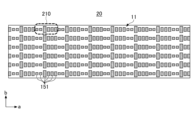
- FIG. 6 is a schematic diagram of a model 20 of the conductive layer 11 used in evaluating reflection efficiency.
- the coordinate space of the evaluation model 20 is a space different from the coordinate space of the wireless transmission system shown in FIG. 1, and the plane in which the conductive layer 11 is formed is the a-b plane, and the axis perpendicular to the a-b plane is the c-axis. .
- the conductive layer 11 includes repeating unit patterns 210 formed of a plurality of metal elements 151.
- the unit pattern 210 is also called a "super cell", and a plurality of metal elements 151 having a long axis in the b direction are arranged at a predetermined pitch in the a direction.
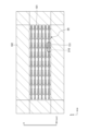
- FIG. 7 is an analysis space 101 for electromagnetic wave simulation
- FIG. 8 is a schematic diagram of the AB plane of the analysis space 101
- FIG. 9 is a schematic diagram of the AC plane of the analysis space 101.
- the size expressed by the a-axis x b-axis x c-axis of the analysis space 101 is 111.8 mm x 32.1 mm x 3.7 mm.
- a model 20 of the conductive layer 11q is arranged in this analysis space 101.
- the model 20 has an 8 ⁇ 6 unit pattern in which eight unit patterns 210 are repeatedly arranged in the a direction and six unit patterns 210 are repeatedly arranged in the b direction.
- the boundary condition is a design in which electromagnetic wave absorbers 102 are arranged around the analysis space 101.
- the unit pattern 210 is designed to reflect vertically incident electromagnetic waves of a predetermined frequency at an angle of 50°.
- the evaluation method uses a model 20 of 8 ⁇ 6 unit patterns 210 in the analysis space 101 shown in FIGS. 7, 8, and 9.
- a plane wave of a predetermined frequency is incident on the model 20 at an incident angle of 0°, and the scattering cross section of the reflected wave is analyzed using general-purpose three-dimensional electromagnetic field simulation software.
- the scattering cross section ie, the radar cross section (RCS)
- RCS radar cross section
- Power reflection efficiency is calculated from the angle and gain (dB) value of the reflected wave.
- the term "reflection efficiency" refers to power reflection efficiency unless otherwise specified.
- the reflection efficiency of the metasurface is a value obtained by dividing the power reflection efficiency obtained from the gain value by the correction value.
- the correction value ⁇ p is
- ⁇ is the angle of incidence on the metasurface
- ⁇ is the corresponding angle of reflection for regular reflection.
- Example 1 is an example
- Example 2 is a comparative example.
- the evaluation items for weather resistance are changes in reflection efficiency, haze value, and YI value after the reflective panel 10 is left in a predetermined environment for a certain period of time.
- the haze value is the ratio (%) of diffused light to the total transmitted light, and serves as an index representing cloudiness or transparency. The higher the haze value, the higher the cloudiness.
- the YI value represents the degree of yellowing, and a change from transparent to yellow is represented by a positive value.
- Example 1 shows simulation results for the configuration of the example.
- a dielectric layer 14 is disposed on at least one side of the conductive layer 11, and the outermost surface of the dielectric layer 14 is covered with a protective layer 16.
- the protective layer 16 contains an ultraviolet absorber. The effect of the protective layer 16 is evaluated by the simulation described above.
- a polycarbonate film with a thickness of 0.7 mm is set as the support layer supporting the conductive layer 11.
- a ground layer of an Ag-based multilayer film with a thickness of 0.36 mm is set on the surface of the polycarbonate film opposite to the conductive layer 11.
- a conductive layer 11 is placed on the supporting surface of the polycarbonate film opposite to the ground layer using an adhesive having a thickness of 0.01 mm.
- the adhesive is applied only to the portions of the unit patterns 210 constituting the conductive layer 11 that support the metal elements 151 .
- the material of the conductive layer 11 is copper foil with a thickness of 0.03 mm.
- a 400 ⁇ m thick adhesive layer 12 is provided to cover the conductive layer 11, and a 2.0 mm thick polycarbonate sheet is bonded to the dielectric layer 14 using the adhesive layer 12.
- a protective layer 16 with a thickness of 8 ⁇ m is placed on the surface of the polycarbonate sheet.
- the protective layer 16 is a resin coat containing an ultraviolet absorber.
- the width of the metal element 151 of the unit pattern 210 included in the conductive layer 11 in the a-axis direction is uniformly 1.6 mm.
- the lengths of the metal elements 151 in the b-axis direction are 2.5663 mm, 2.9113 mm, 4.0717 mm, 1.2521 mm, 1.8975 mm, and 2.5357 mm, respectively.
- the area occupation rate of the metal element 151 with respect to the dielectric layer 14 is 32.6%, and the transmittance to visible light is 43.1%.
- the calculation is performed again after this reflective panel has been left in an environment of 60° C. and 95% humidity for 500 hours.
- a 28.0 GHz electromagnetic wave incident at an incident angle of 0° is reflected at a reflection angle of 50°
- the gain value at 50° of the RCS plot is -1.4735 dB
- the amount of change in haze value was 3.0%
- the amount of change ⁇ YI in YI value was 2.0%.
- Example 1 by providing the protective layer 16 containing an ultraviolet absorber on the surface of the dielectric layer 14 covering the conductive layer 11, the reduction in reflection efficiency after being left in a high temperature and high humidity environment for 500 hours was reduced by 7. It is suppressed to about %. Further, the increase in haze value was only 3.0%, and the amount of change in ⁇ YI was 2.0%, indicating that the transparency of the reflective panel 10 was maintained.
- Example 2 shows simulation results of a comparative example. The conditions are the same as in Example 1, except that no protective layer is provided on the surface of the dielectric layer 14.
- the layer structure of the reflective panel excluding the protective layer, the width and length of the metal element 151 of the unit pattern 210, and the area occupation ratio and transmittance of the metal element 151 with respect to the dielectric layer are all the same as in Example 1.
- the calculation is performed again after the reflective panel of Example 2 is left in an environment of 60° C. and 95% humidity for 500 hours.
- a 28.0 GHz electromagnetic wave incident at an incident angle of 0° is reflected at a reflection angle of 50°
- the gain value at 50° of the RCS plot is -2.9630 dB
- the amount of change in haze value was 10.0%
- the amount of change ⁇ YI in YI value which represents the degree of yellowing, was 18.0%.
- the reflection efficiency decreases to 55.0% when left in a high temperature and high humidity environment for the same period of time. This is lower than the standard reflection efficiency of 60.0%. It can be seen that the haze value increased by 10.0%, the ⁇ YI was as large as 18.0%, the yellowing of the reflective panel became noticeable, and the transparency deteriorated.
- Examples 3 to 6 show the evaluation results of the mechanical strength of the reflective panel 10.
- the mechanical strength of the reflective panel 10 is evaluated in accordance with a strength test and an impact performance test based on NEXCO (Nippon Expressway Company Limited) test methods 901 and 902.
- Examples 3 and 4 show the evaluation results of the configurations of the examples, and Examples 5 and 6 show the evaluation results of the comparative examples.
- Example 3 shows the evaluation results of mechanical strength of Examples.
- dielectric layers 14 and 15 made of two flat polycarbonate sheets each having a length of 1.0 m, a width of 2.0 m, and a thickness of 8.0 mm are set on both sides of the conductive layer 11.
- the conductive layer 11 is a stainless steel mesh with a thickness of 100.0 ⁇ m.
- Adhesive layers 12 and 13 of ethylene vinyl acetate having a thickness of 400 ⁇ m are set between dielectric layers 14 and 15 of polycarbonate sheets and conductive layer 11.
- Protective layers 16 and 17 containing an ultraviolet absorber and having a thickness of 7.0 ⁇ m are set on the surfaces of the dielectric layers 14 and 15.
- the reflective panel of Example 3 was subjected to an impact with a 300 kg iron ball, and the scattering prevention rate was measured.
- the scattering prevention rate of the reflective panel of Example 3 was as high as 99%, and only 1% of the light-transmitting portion (that is, the dielectric layer and the protective layer) was scattered as fragments. Further, the maximum weight of the fragments of the transparent part is 1.5 g or less, which is lightweight.
- the strength test is evaluated by measuring the amount of deflection at the center of the reflective panel and confirming that the ratio of the amount of deflection to the short side (1.0 m) of the reflective panel is 1/15 or less.
- the amount of deflection at the center of the reflective panel of Example 3 was 1/15 or less of the length of the short side, and both impact resistance and strength were good.
- Example 4 shows the mechanical strength evaluation results of the examples.
- the layer structure of the reflective panel of Example 4 is the same as that of the reflective panel of Example 3, except that the thickness of the polycarbonate sheets forming dielectric layers 14 and 15 was changed to 5.0 mm.
- the conductive layer 11 is made of stainless steel mesh with a thickness of 100.0 ⁇ m
- the adhesive layers 12 and 13 are made of ethylene vinyl acetate with a thickness of 400 ⁇ m
- the protective layers 16 and 17 are made of resin containing an ultraviolet absorber with a thickness of 7.0 ⁇ m. It is a layer.
- the shatter prevention rate of the reflective panel of Example 4 using a polycarbonate sheet dielectric layer with a thickness of 5.0 mm and a protective layer with a thickness of 7.0 ⁇ m was the same as in Example 3. As high as 99%.
- the maximum weight of the fragments of the transparent part is 1.5 g or less. It was confirmed that the amount of deflection at the center of the reflective panel was 1/15 or less of the short side (1.0 m) of the reflective panel.
- the reflective panel of Example 4 has good impact resistance and strength.
- Example 5 shows the evaluation results of the mechanical strength of the reflective panel of the comparative example.
- the layer structure of the reflective panel of Example 5 was such that the thickness of the polycarbonate sheet forming the dielectric layers 14 and 15 was changed to 1.0 mm, and the protective layers 16 and 17 on the surfaces of the dielectric layers 14 and 15 were changed to 1.0 mm.
- the layer structure was the same as that of the reflective panels of Examples 3 and 4, except that the thickness was changed to 0.5 ⁇ m.
- the shatter prevention rate of the reflective panel of Example 5 using a dielectric layer of a polycarbonate sheet with a thickness of 1.0 mm and a protective layer with a thickness of 0.5 ⁇ m was less than 99%. Become. This indicates that the weight of scattered fragments of the transparent portion is large. The maximum weight of the fragments in the transparent part exceeded 1.5 g. The amount of deflection at the center of the reflective panel in the strength test was greater than 1/15 of the short side (1.0 m) of the reflective panel, confirming that the reflective panel was highly distorted. The reflective panel of Example 5 has insufficient impact resistance and strength.
- Example 6 shows the evaluation results of the mechanical strength of a reflective panel of another comparative example.
- the layer structure of the reflective panel of Example 6 was such that the thickness of the polycarbonate sheet forming the dielectric layers 14 and 15 was changed to 1.0 mm, and the thickness of the stainless steel mesh forming the conductive layer 11 was changed to 5.0 mm.
- the layer structure is the same as that of the reflective panels of Examples 3 and 4, except that the thickness was changed to 0 ⁇ m.
- the shatter prevention rate of the reflective panel of Example 6 using a 1.0 mm thick polycarbonate sheet and a 7.0 ⁇ m thick protective layer is less than 99%.
- the thickness of the protective layer is the same as in Examples 3 and 4, the scattering prevention rate is less than 99.9% because the dielectric layers 14 and 15 of the polycarbonate sheet are thinner and the mechanical strength is lower. This is thought to be due to a decrease in Moreover, the maximum weight of the fragments of the transparent part exceeds 1.5 g. The fact that the maximum weight of the fragments in the light-transmitting part exceeds 1.5 g even though the polycarbonate sheet has become thinner indicates that the scattered fragments are large.
- the amount of deflection at the center of the reflective panel in the strength test was greater than 1/15 of the short side (1.0 m) of the reflective panel, confirming that the reflective panel was highly distorted.
- the reflective panel of Example 6 has insufficient impact resistance and strength.
- the ratio of the thickness of the dielectric layer 14 or 15 to the thickness of the protective layer 16 or 17 is preferably in the range of 50:1 to 200:1.
- the ratio of the thickness of the dielectric layer 14 or 15 to the conductive layer 11 is preferably greater than 5 and 100 or less.
- FIG. 10 is a top view of the simulation model 200 of the wireless transmission system
- FIG. 11 is a perspective view of the simulation model 200 of the wireless transmission system.
- the model 200 is a road 32 that includes vehicles 31a and 31b, a plate 38, a pillar 39 that supports the plate 38, and the like.
- the road 32 has a width of 14.0 m and a length of 200.0 m.
- a transmitting station Tx1 is arranged on one side of the road 32, and transmitting stations Tx2 are arranged alternately on the other side.
- electromagnetic wave reflecting devices 60 of the type of FIG. 2A are arranged on both sides of the road 32.
- a light-transmitting sound insulating wall may be provided along the electromagnetic wave reflecting device 60 or integrally with the electromagnetic wave reflecting device 60.
- FIG. 12 shows the material and coordinates of the object used in the model 200 of FIGS. 10 and 11.
- the body of the vehicle 31a is made of metal, and has a length of 4.1 m, a width of 1.7 m, and a height of 1.5 m.
- the body of the vehicle 31b is made of metal, and has a length of 4.8 m, a width of 1.7 m, and a height of 1.5 m.
- the road 32 is a concrete roadway, and has a width of 14.0 m and a length of 200.0 m as described above.
- the plate 38 is a floorboard for 5 GHz wireless LAN of I ⁇ U (International Telecommunication Union), and has a width of 8.0 m, a thickness of 0.075 m, and a height of 5.0 m.
- the pillar 39 is made of metal and has a diameter of 0.2 m, a height of 5.0 m, and a length in the Y direction of 14.0 m.
- the electromagnetic wave reflecting device 60 is placed across the road 32 with a length of 200.0 m. Specifically, 100 reflective panels with a width of 2.0 m x a height of 1.0 m are connected in the X direction and made into 4 stages in the height (Z) direction, so that a total of 400 panels are connected and the height is 4. .0m fence.
- the conductive layer 11 of the reflective panel 10 is made of metal (stainless steel).
- the transmitting antennas of transmitting stations Tx1 and Tx2 are installed at a height of 3.0 m.
- the beam widths of both transmitting antennas are 28°.
- the antenna of the receiver Rx is an omnidirectional antenna with a height of 1.0 m and a maximum gain of 0 dBi.
- the receiver Rx measures received power at all positions within a plane at a height of 1.0 m on the road 32 parallel to the XY plane.
- Examples 7 to 11 are configurations using the reflective panels of the embodiments, and Examples 8 and 10 are configurations using only normal light-transmitting sound insulating walls as comparative examples.
- FIG. 13 shows the received power distribution of the configuration of Example 7.
- an electromagnetic wave reflective fence with a height of 4.0 m, in which 400 reflective panels 10 with a width x height of 2.0 m x 1.0 m are connected on each side, is installed on both sides of the road 32 shown in Figures 10 and 11.
- the transmitting antennas of the transmitting stations Tx1 and Tx2 are installed on both sides of the road 32 at a height of 3.0 m.
- the transmission frequency of the transmitting stations Tx1 and Tx2 is 4.7 GHz, and the maximum gain of the transmitting antenna is 20 dBi.
- the received power distribution in a plane parallel to the XY plane and a height of 1.0 m is measured using an omnidirectional receiving antenna.
- the total sum of in-plane RSRP (Reference Signal Received Power) is -287.326 dBm, and the median value is -89 dBm.
- the radio wave strength outside the road is lower than -100 dBm.
- Example 7 The evaluation results of Example 7 are valid for the frequency band below 6 GHz, and the median received power inside the road 32 is -90 dBm or more, and the received power outside the road is lower than inside the road and less than -100 dBm.
- FIG. 14 shows the received power distribution of the configuration of Example 8.
- Example 8 is a configuration of a comparative example, and instead of the electromagnetic wave reflection device 60, transparent sound insulation walls made of polycarbonate and having a height of 4.0 m are set on both sides of the road 32.
- the length of the transparent sound insulating wall is 200 m on one side and 400 m on both sides.
- Other conditions are the same as in Example 7.
- the transmitting stations Tx1 and Tx2 transmit reference signals of 4.7 GHz from a height of 3.0 m on both sides of the road 32.
- the maximum gain of the transmitting antenna is 20 dBi as in Example 7.
- the total RSRP is -372.833 dBm, and the median value is -107 dBm.
- the maximum received power of radio waves outside the road is -80 dBm, which is high.
- uplink throughput is measured in the area behind the electromagnetic wave reflector 60, a maximum of 80% of the transmission rate is achieved. This means that the radio waves radiated from the transmitting stations Tx1 and Tx2 are leaking to the outside of the transparent sound insulating wall at high power.
- FIG. 15 shows the received power distribution of the configuration of Example 9.
- Example 9 has the same conditions as Example 7, except that the transmission frequencies of transmitting stations Tx1 and Tx2 were changed to 28.3 GHz.
- an electromagnetic wave reflecting fence with a height of 4.0 m is provided by connecting 400 reflective panels 10 with a width x height of 2.0 m x 1.0 m on each side and 800 pieces on each side.
- the transmitting stations Tx1 and Tx2 are installed at a height of 3.0 m on both sides of the road 32, and transmit a 28.3 GHz reference signal from transmitting antennas with a maximum gain of 20 dBi.
- the total sum of RSRP in a plane with a height of 1.0 m parallel to the XY plane is -399.424 dBm, and the median value is -125 dBm.
- the received power outside the road is lower than -125 dBm.
- the electromagnetic wave reflection device 60 can improve the radio wave propagation environment on the road 32 and suppress the leakage of radio waves to the outside of the road 32 even for radio waves in the 28 GHz band.
- the results of Example 9 apply to communication in the millimeter wave band from 28 GHz to 80 GHz, and the median received power inside the road 32 is -125 dBm or more, and the received power outside the road 32 is less than -125 dBm.
- FIG. 16 shows the received power distribution of the configuration of Example 10.
- Example 10 is a configuration of a comparative example, in which polycarbonate panels with a width of 2.0 m x 1.0 m and a height of 4.0 m are connected on both sides of the road 32 in place of the electromagnetic wave reflecting device 60. , a transparent sound barrier made of polycarbonate will be installed. The conditions are the same as in Example 8, except that the transmission frequencies of transmitting stations Tx1 and Tx2 were changed to 28.3 GHz.
- the 4.0 m high translucent sound barrier is 200 m long on one side and 400 m long on both sides.
- the transmitting stations Tx1 and Tx2 transmit reference signals of 28.3 GHz from a height of 3.0 m on both sides of the road 32.
- the maximum gain of the transmitting antenna is 20 dBi, the same as in Examples 7 to 9.
- the total RSRP is -496.329 dBm, and the median value is -145 dBm.
- the radio wave power outside the road is as high as -100 dBm.
- uplink throughput is measured in the area behind the electromagnetic wave reflection device 60, a maximum of 80% of the transmission rate is achieved. It can be seen that the 28 GHz band radio waves emitted from the transmitting stations Tx1 and Tx2 cannot efficiently cover the communication area on the road 32, and conversely leak to the outside of the transparent sound insulating wall.
- FIG. 17 shows the received power distribution of the configuration of Example 11.
- the electromagnetic wave absorber 35 is combined with the reflective panel 10 of the embodiment.
- 400 reflective panels 10 with a width x height of 2.0 m x 1.0 m are connected on one side and a total of 800 on both sides.
- an electromagnetic wave absorber 35 an electromagnetic wave absorbing panel made of polymer fiber and having a height of 2.0 m is installed over a length of 200 m on one side and 400 m on both sides, making the total height 6.0 m. .
- the transmitting stations Tx1 and Tx2 are installed at a height of 3.0 m on both sides of the road 32, and transmit a 4.7 GHz reference signal from transmitting antennas with a maximum gain of 20 dBi.
- the total sum of RSRP in a plane with a height of 1.0 m parallel to the XY plane is -359.761 dBm, and the median value is -110 dBm. Radio field strength outside the road is lower than -110 dBm.
- Example 11 When the electromagnetic wave absorber 35 is connected to the upper end of the electromagnetic wave reflector 60, the intensity of the received power on the road 32 is slightly lower than in Example 7, but it is possible to effectively prevent radio waves from jumping out to the outside of the road 32.
- the calculation results of Example 11 apply to frequency bands below 6 GHz.
- FIG. 18 shows the received power distribution of the configuration of Example 12.
- Example 12 has the same conditions as Example 11, except that the maximum gains of transmitting stations ⁇ x1 and Tx2 are changed to 10 dBi.
- 400 reflective panels 10 with a width x height of 2.0 m x 1.0 m are connected on one side and a total of 800 panels on both sides, and on top of the reflective panels 10, electromagnetic waves with a height of 2.0 m formed of polymer fibers are placed.
- Absorbent panels will be installed for 200m on one side and 400m on both sides.
- the transmitting stations Tx1 and Tx2 are installed at a height of 3.0 m on both sides of the road 32, and transmit a 4.7 GHz reference signal from transmitting antennas with a maximum gain of 10 dBi.
- the total sum of RSRP in a plane with a height of 1.0 m parallel to the XY plane is -359.759 dBm, and the median value is -110 dBm. Radio field strength outside the road is lower than -110 dBm.
- the received power intensity on the road 32 is slightly lower than in Example 7, but it is possible to effectively prevent radio waves from jumping out to the outside of the road 32.
- the received power distribution on the road 32 in a plane with a height of 1 m parallel to the XY plane is affected by the maximum gain of the transmitting antenna of the transmitting station Tx within a range of 5 dBi or more and 30 dBi or less, preferably 10 dBi or more and 20 dBi or less. It turns out that there isn't.
- the calculation results of Example 12 apply to frequency bands below 6 GHz.
- Example 13 is an example.
- 400 reflective panels 10 with a width x height of 2.0 m x 1.0 m are connected on one side and 800 on both sides on both sides of the road 32, resulting in a height of 4.0 m.
- the difference from Example 9 is that in the vicinity of the base station, a ceiling panel 110 (see FIG. 4) is provided to cover the 14 m wide road 32 over a 5 m long range of the road 32.
- the transmitting antennas of the transmitting stations Tx1 and Tx2 are installed at a height of 3.0 m on both sides of the road 32, and transmit a 28.3 GHz reference signal from the transmitting antennas with a maximum gain of 20 dBi.
- the ceiling panel 110 By providing the ceiling panel 110 over a length of 5 m, the total RSRP in a plane with a height of 1.0 m parallel to the XY plane on the road 32 is -248.723 dBm, and the median value is -85 dBm. be.
- the received power outside the road 32 that is, in the area behind the electromagnetic wave reflecting device 60 as seen from the road 32, is lower than -125 dBm.
- the uplink throughput was measured in the area behind the electromagnetic wave reflection device 60, it was less than 50% of the transmission rate.
- Even if the length is 5 m by providing the ceiling panel 110, it is possible to suppress scattered light from vehicles and structures from jumping out of the road 32. It can be seen that the radio wave propagation environment on the road 32 can be improved for radio waves in the 28 GHz band, and leakage of radio waves to the outside of the road 32 can be suppressed.
- Example 14 is an example.
- 400 reflective panels 10 with a width x height of 2.0 m x 1.0 m are connected on each side and 800 on both sides on both sides of the road 32, resulting in a height of 4.0 m.
- the difference from Example 13 is that a ceiling panel 110 (see FIG. 4) is provided near the base station to cover the 14 m wide road 32 over the 10 m long range of the road 32.
- the transmitting antennas of the transmitting stations Tx1 and Tx2 are installed at a height of 3.0 m on both sides of the road 32, and transmit a 28.3 GHz reference signal from the transmitting antennas with a maximum gain of 20 dBi.
- the ceiling panel 110 By providing the ceiling panel 110 over a length of 5 m, the total RSRP in a plane with a height of 1.0 m parallel to the XY plane on the road 32 is -235.767 dBm, and the median value is -80 dBm. .
- the uplink throughput was measured in the area behind the electromagnetic wave reflection device 60, it was less than 50% of the transmission rate. It can be seen that by providing the ceiling panel 110, it is possible to improve the radio wave propagation environment on the road 32 for radio waves in the 28 GHz band, and to suppress leakage of radio waves to the outside of the road 32.
- the wireless transmission system or reflective panel of the embodiment it is possible to improve the radio wave propagation environment and suppress radio waves from ejecting outside the required space in an indoor facility that is outdoors or in an environment close to the outdoors. can be done. Even if the transmitting antenna of the base station is located higher than the top of the electromagnetic wave reflector, the radiation angle of the transmitting beam is controlled so that the output electromagnetic waves of the base station's transmitting antenna are incident on the surface of the electromagnetic wave reflector. By doing so, it is possible to improve the radio wave propagation environment within the required space and to suppress the radio waves from jumping out of the required space.
- the wireless transmission system 1 of the embodiment is suitably applied to areas extending in a predetermined direction, such as general roads, expressways, railway tracks, and tunnels, but is also suitable for applications such as electronic toll collection systems, streets, rotaries, commercial It can also be applied to terraces, arcades, etc. of facilities and public facilities.
- a predetermined direction such as general roads, expressways, railway tracks, and tunnels
- applications such as electronic toll collection systems, streets, rotaries, commercial
- it can also be applied to terraces, arcades, etc. of facilities and public facilities.
- it is possible to reduce dead zones on expressways and tunnels where noise barriers and safety fences are installed on both sides, improve the radio wave propagation environment, and suppress radio waves from escaping outside the expressway.
- the size of the reflecting surface of the electromagnetic wave reflecting device 60 can be appropriately designed depending on the application situation, and as an example, a size of 10 cm x 10 cm to 2.0 m x 4.0 m may be used.
- the height of the antenna of the base station 33 is not limited to 3.0 m, and may be at a position higher than the upper end of the electromagnetic wave reflecting device 60. In other words, the height, orientation, and assembly method of the electromagnetic wave reflection device 60 can be designed depending on the position of the transmitting antenna of the base station installed in the environment to which the electromagnetic wave reflection device 60 is applied.
- the ultraviolet absorber used in the outermost protective layer of the reflective panel and the material of the electromagnetic wave absorbing panel used in combination with the electromagnetic wave reflecting device can be selected as appropriate depending on the application environment.
- the wireless transmission system 1 may be configured by connecting electromagnetic wave reflecting devices 60B having a reflecting panel 10B including a curved surface as shown in FIG. 2B.
- the ceiling panel 110 may be combined with the electromagnetic wave reflecting fence 100B to which the electromagnetic wave reflecting device 60B is connected.
- Two or more electromagnetic wave reflecting devices 60 (including 60A, 60B, and 60C) or two or more sets of electromagnetic wave reflecting fences 100 may be installed in parallel or non-parallel to surround a predetermined space, or
- the ceiling panel 110 may be combined in a similar arrangement.
- the first electromagnetic wave reflecting device 60 may be arranged along the first direction in a predetermined area within the communication area of the base station, and the second electromagnetic wave reflecting device 60 may be arranged along the second direction. good.
- the first direction and the second direction may be the same or different.
- the first electromagnetic wave reflecting device and the second electromagnetic wave reflecting device may be combined with a ceiling panel 110 that covers a predetermined area.
- a ceiling panel 110 may be provided to cover the upper end of the electromagnetic wave absorption panel.
- a plurality of reflective panels may be connected in the width direction, and at least a portion thereof may be continuously installed along an area extending in a certain direction, such as a road. Frequencies used in wireless transmission systems are not limited to the 4.7 GHz and 28 GHz bands.
- a base station that is installed outdoors or in an environment close to outdoors and communicates wirelessly in a predetermined frequency band of 1 GHz or more and 300 GHz or less; an electromagnetic wave reflecting device having a reflective panel that reflects electromagnetic waves in the predetermined frequency band and provided along a predetermined area within the communication area of the base station;
- the transmitting antenna of the base station forms a transmitting beam toward the predetermined area so that the output electromagnetic wave is incident at a position lower than the height of the top of the electromagnetic wave reflecting device,
- the reflective panel is located within a range of 5.0 m or more and 300.0 m or less from the transmitting antenna at the shortest distance, and reflects electromagnetic waves in the predetermined frequency band into the predetermined area
- a wireless transmission system wherein received power outside the predetermined area is lower than an average value or median value of received power within the predetermined area.
- the predetermined frequency band includes frequencies below 6 GHz, the average or median value of received power within the predetermined region is higher than ⁇ 90 dBm, and the received power outside the predetermined region is higher than ⁇ 100 dBm. low,
- the wireless transmission system according to item 1. (Section 3)
- the predetermined frequency band is a millimeter wave band, the average value or median value of received power within the predetermined region is ⁇ 125 dBm or more, and the received power outside the predetermined region is lower than ⁇ 125 dBm.
- the wireless transmission system according to item 1. (Section 4)
- the predetermined area is a road, and the electromagnetic wave reflecting device is provided along at least one side of the road.
- a plurality of reflective panels are connected in the width direction and at least a portion thereof is continuously provided along the road.
- the wireless transmission system according to item 4. the reflective panel includes a curved surface;
- the wireless transmission system according to any one of Items 1 to 5. (Section 7) a first electromagnetic wave reflecting device disposed in a first direction in the predetermined region; and a second electromagnetic wave reflecting device disposed in a second direction different from the first direction. 7.
- the wireless transmission system according to any one of Items 1 to 6. (Section 8) a ceiling panel that covers at least a portion of the predetermined area; has, 8.
- the maximum gain of the transmitting antenna of the base station is 5 dBi or more and 30 dBi or less, 9.
- the wireless transmission system according to any one of Items 1 to 8. (Section 10) an electromagnetic wave absorber provided at the upper end of the reflective panel; has, 10.
- the wireless transmission system according to any one of Items 1 to 9. (Section 11)
- the reflective panel has a protective layer containing an ultraviolet absorber as the outermost layer.
- the wireless transmission system according to any one of Items 1 to 10. Item 12.
- the wireless transmission system according to Item 11 wherein the thickness of the reflective panel is 5.0 mm or more and 17.0 mm or less, and the ratio of the thickness of the reflective panel to the thickness of the protective layer is 350 or more and 1000 or less.
- Electromagnetic wave absorber 50 50A, 50B, 550 frame (side frame) 57 Top frame 58 Bottom frame 60, 60A, 60B, 60C Electromagnetic wave reflecting device 100A, 100B, 100C, 100-1, 100-2, 300 Electromagnetic wave reflecting fence 110 Ceiling panel 151 Metal element 210 Unit pattern Tx, Tx1, Tx2 Transmitting station
Landscapes
- Physics & Mathematics (AREA)
- Electromagnetism (AREA)
- Engineering & Computer Science (AREA)
- Microelectronics & Electronic Packaging (AREA)
- Aerials With Secondary Devices (AREA)
- Radio Relay Systems (AREA)
Priority Applications (1)
| Application Number | Priority Date | Filing Date | Title |
|---|---|---|---|
| JP2024541438A JPWO2024038682A1 (https=) | 2022-08-17 | 2023-06-27 |
Applications Claiming Priority (4)
| Application Number | Priority Date | Filing Date | Title |
|---|---|---|---|
| JP2022130005 | 2022-08-17 | ||
| JP2022-130005 | 2022-08-17 | ||
| JP2022-182434 | 2022-11-15 | ||
| JP2022182434 | 2022-11-15 |
Publications (1)
| Publication Number | Publication Date |
|---|---|
| WO2024038682A1 true WO2024038682A1 (ja) | 2024-02-22 |
Family
ID=89941467
Family Applications (1)
| Application Number | Title | Priority Date | Filing Date |
|---|---|---|---|
| PCT/JP2023/023717 Ceased WO2024038682A1 (ja) | 2022-08-17 | 2023-06-27 | 無線伝達システム |
Country Status (3)
| Country | Link |
|---|---|
| JP (1) | JPWO2024038682A1 (https=) |
| TW (1) | TW202410551A (https=) |
| WO (1) | WO2024038682A1 (https=) |
Citations (3)
| Publication number | Priority date | Publication date | Assignee | Title |
|---|---|---|---|---|
| WO2021199504A1 (ja) * | 2020-03-31 | 2021-10-07 | Agc株式会社 | 無線伝達システム |
| JP2021175054A (ja) * | 2020-04-22 | 2021-11-01 | Kddi株式会社 | メタサーフェス反射板アレイ |
| WO2022196338A1 (ja) * | 2021-03-16 | 2022-09-22 | Agc株式会社 | 電磁波反射装置、電磁波反射フェンス、及び電磁波反射装置の組み立て方法 |
-
2023
- 2023-06-27 JP JP2024541438A patent/JPWO2024038682A1/ja active Pending
- 2023-06-27 WO PCT/JP2023/023717 patent/WO2024038682A1/ja not_active Ceased
- 2023-06-30 TW TW112124548A patent/TW202410551A/zh unknown
Patent Citations (3)
| Publication number | Priority date | Publication date | Assignee | Title |
|---|---|---|---|---|
| WO2021199504A1 (ja) * | 2020-03-31 | 2021-10-07 | Agc株式会社 | 無線伝達システム |
| JP2021175054A (ja) * | 2020-04-22 | 2021-11-01 | Kddi株式会社 | メタサーフェス反射板アレイ |
| WO2022196338A1 (ja) * | 2021-03-16 | 2022-09-22 | Agc株式会社 | 電磁波反射装置、電磁波反射フェンス、及び電磁波反射装置の組み立て方法 |
Also Published As
| Publication number | Publication date |
|---|---|
| JPWO2024038682A1 (https=) | 2024-02-22 |
| TW202410551A (zh) | 2024-03-01 |
Similar Documents
| Publication | Publication Date | Title |
|---|---|---|
| KR20220043213A (ko) | 빔 형성 시스템을 위한 메타 구조의 무선 인프라구조 | |
| US20250174903A1 (en) | Frequency-selective reflecting plate and communication relay system | |
| US20250309551A1 (en) | Radio transmission system | |
| US20250309549A1 (en) | Electromagnetic wave reflector, electromagnetic wave reflective fence, and method of assembling electromagnetic wave reflector | |
| US9793973B2 (en) | Non-feeding reradiating repeater and method for manufacturing of the same | |
| KR20100072383A (ko) | 전자파 흡수체를 구비한 운송수단 용 자동 요금 징수 시스템, 운송용 장치, 건물형 구조물, 전자기기, 전자파 무반사실 | |
| US20250055201A1 (en) | Electromagnetic wave reflecting device, electromagnetic wave reflecting fence, and reflection panel | |
| TW202245339A (zh) | 相位調整板、玻璃板及無線通信系統 | |
| WO2023153328A1 (ja) | フレネルゾーンプレートレンズ、フレネルゾーンプレートレンズ一体型窓ガラス、及びフレネルゾーンプレートレンズ付き窓ガラス | |
| CN116111335A (zh) | 透光天线 | |
| WO2023218887A1 (ja) | 電磁波反射装置、及び電磁波反射フェンス | |
| WO2023120471A1 (ja) | 電波集束体、窓ガラス、及び、電波通信システム | |
| WO2024038682A1 (ja) | 無線伝達システム | |
| US20250096480A1 (en) | Electromagnetic wave reflecting device, electromagnetic wave reflecting fence, and reflection panel | |
| WO2024038775A1 (ja) | 反射パネル、電磁波反射装置、及び電磁波反射フェンス | |
| JP7673754B2 (ja) | アンテナセット | |
| WO2023120138A1 (ja) | 無線伝達システム、及び電磁波反射装置 | |
| TW202425422A (zh) | 反射板、使用其之電磁波反射裝置及電磁波反射柵 | |
| US20240145937A1 (en) | Radio wave control system | |
| US20250324282A1 (en) | Radio transmission system | |
| WO2026058743A1 (ja) | 電磁波反射装置、電磁波反射フェンス、及び電磁波反射装置の組み立て方法 | |
| EP4693745A1 (en) | Reflector | |
| WO2025100389A1 (ja) | 電磁波反射フィルム、及び電磁波反射フィルムのタイリング方法 | |
| WO2025005023A1 (ja) | 電磁波反射遮音装置、及び無線伝達システム | |
| WO2025105163A1 (ja) | 無線伝達システム |
Legal Events
| Date | Code | Title | Description |
|---|---|---|---|
| 121 | Ep: the epo has been informed by wipo that ep was designated in this application |
Ref document number: 23854720 Country of ref document: EP Kind code of ref document: A1 |
|
| WWE | Wipo information: entry into national phase |
Ref document number: 2024541438 Country of ref document: JP |
|
| NENP | Non-entry into the national phase |
Ref country code: DE |
|
| 122 | Ep: pct application non-entry in european phase |
Ref document number: 23854720 Country of ref document: EP Kind code of ref document: A1 |