WO2024034499A1 - 正極合材、正極合材の製造方法及びリチウムイオン電池 - Google Patents
正極合材、正極合材の製造方法及びリチウムイオン電池 Download PDFInfo
- Publication number
- WO2024034499A1 WO2024034499A1 PCT/JP2023/028345 JP2023028345W WO2024034499A1 WO 2024034499 A1 WO2024034499 A1 WO 2024034499A1 JP 2023028345 W JP2023028345 W JP 2023028345W WO 2024034499 A1 WO2024034499 A1 WO 2024034499A1
- Authority
- WO
- WIPO (PCT)
- Prior art keywords
- positive electrode
- composite material
- electrode composite
- diffraction peak
- solid electrolyte
- Prior art date
- Legal status (The legal status is an assumption and is not a legal conclusion. Google has not performed a legal analysis and makes no representation as to the accuracy of the status listed.)
- Ceased
Links
Images

Classifications
-
- H—ELECTRICITY
- H01—ELECTRIC ELEMENTS
- H01M—PROCESSES OR MEANS, e.g. BATTERIES, FOR THE DIRECT CONVERSION OF CHEMICAL ENERGY INTO ELECTRICAL ENERGY
- H01M4/00—Electrodes
- H01M4/02—Electrodes composed of, or comprising, active material
- H01M4/13—Electrodes for accumulators with non-aqueous electrolyte, e.g. for lithium-accumulators; Processes of manufacture thereof
- H01M4/136—Electrodes based on inorganic compounds other than oxides or hydroxides, e.g. sulfides, selenides, tellurides, halogenides or LiCoFy
-
- H—ELECTRICITY
- H01—ELECTRIC ELEMENTS
- H01M—PROCESSES OR MEANS, e.g. BATTERIES, FOR THE DIRECT CONVERSION OF CHEMICAL ENERGY INTO ELECTRICAL ENERGY
- H01M10/00—Secondary cells; Manufacture thereof
- H01M10/05—Accumulators with non-aqueous electrolyte
- H01M10/052—Li-accumulators
-
- H—ELECTRICITY
- H01—ELECTRIC ELEMENTS
- H01M—PROCESSES OR MEANS, e.g. BATTERIES, FOR THE DIRECT CONVERSION OF CHEMICAL ENERGY INTO ELECTRICAL ENERGY
- H01M10/00—Secondary cells; Manufacture thereof
- H01M10/05—Accumulators with non-aqueous electrolyte
- H01M10/056—Accumulators with non-aqueous electrolyte characterised by the materials used as electrolytes, e.g. mixed inorganic/organic electrolytes
- H01M10/0561—Accumulators with non-aqueous electrolyte characterised by the materials used as electrolytes, e.g. mixed inorganic/organic electrolytes the electrolyte being constituted of inorganic materials only
- H01M10/0562—Solid materials
-
- H—ELECTRICITY
- H01—ELECTRIC ELEMENTS
- H01M—PROCESSES OR MEANS, e.g. BATTERIES, FOR THE DIRECT CONVERSION OF CHEMICAL ENERGY INTO ELECTRICAL ENERGY
- H01M4/00—Electrodes
- H01M4/02—Electrodes composed of, or comprising, active material
- H01M4/36—Selection of substances as active materials, active masses, active liquids
- H01M4/38—Selection of substances as active materials, active masses, active liquids of elements or alloys
-
- H—ELECTRICITY
- H01—ELECTRIC ELEMENTS
- H01M—PROCESSES OR MEANS, e.g. BATTERIES, FOR THE DIRECT CONVERSION OF CHEMICAL ENERGY INTO ELECTRICAL ENERGY
- H01M4/00—Electrodes
- H01M4/02—Electrodes composed of, or comprising, active material
- H01M4/36—Selection of substances as active materials, active masses, active liquids
- H01M4/58—Selection of substances as active materials, active masses, active liquids of inorganic compounds other than oxides or hydroxides, e.g. sulfides, selenides, tellurides, halogenides or LiCoFy; of polyanionic structures, e.g. phosphates, silicates or borates
- H01M4/581—Chalcogenides or intercalation compounds thereof
- H01M4/5815—Sulfides
-
- H—ELECTRICITY
- H01—ELECTRIC ELEMENTS
- H01M—PROCESSES OR MEANS, e.g. BATTERIES, FOR THE DIRECT CONVERSION OF CHEMICAL ENERGY INTO ELECTRICAL ENERGY
- H01M4/00—Electrodes
- H01M4/02—Electrodes composed of, or comprising, active material
- H01M4/62—Selection of inactive substances as ingredients for active masses, e.g. binders, fillers
-
- H—ELECTRICITY
- H01—ELECTRIC ELEMENTS
- H01M—PROCESSES OR MEANS, e.g. BATTERIES, FOR THE DIRECT CONVERSION OF CHEMICAL ENERGY INTO ELECTRICAL ENERGY
- H01M4/00—Electrodes
- H01M4/02—Electrodes composed of, or comprising, active material
- H01M4/62—Selection of inactive substances as ingredients for active masses, e.g. binders, fillers
- H01M4/624—Electric conductive fillers
- H01M4/625—Carbon or graphite
-
- H—ELECTRICITY
- H01—ELECTRIC ELEMENTS
- H01M—PROCESSES OR MEANS, e.g. BATTERIES, FOR THE DIRECT CONVERSION OF CHEMICAL ENERGY INTO ELECTRICAL ENERGY
- H01M4/00—Electrodes
- H01M4/02—Electrodes composed of, or comprising, active material
- H01M2004/021—Physical characteristics, e.g. porosity, surface area
-
- H—ELECTRICITY
- H01—ELECTRIC ELEMENTS
- H01M—PROCESSES OR MEANS, e.g. BATTERIES, FOR THE DIRECT CONVERSION OF CHEMICAL ENERGY INTO ELECTRICAL ENERGY
- H01M4/00—Electrodes
- H01M4/02—Electrodes composed of, or comprising, active material
- H01M2004/026—Electrodes composed of, or comprising, active material characterised by the polarity
- H01M2004/028—Positive electrodes
-
- Y—GENERAL TAGGING OF NEW TECHNOLOGICAL DEVELOPMENTS; GENERAL TAGGING OF CROSS-SECTIONAL TECHNOLOGIES SPANNING OVER SEVERAL SECTIONS OF THE IPC; TECHNICAL SUBJECTS COVERED BY FORMER USPC CROSS-REFERENCE ART COLLECTIONS [XRACs] AND DIGESTS
- Y02—TECHNOLOGIES OR APPLICATIONS FOR MITIGATION OR ADAPTATION AGAINST CLIMATE CHANGE
- Y02E—REDUCTION OF GREENHOUSE GAS [GHG] EMISSIONS, RELATED TO ENERGY GENERATION, TRANSMISSION OR DISTRIBUTION
- Y02E60/00—Enabling technologies; Technologies with a potential or indirect contribution to GHG emissions mitigation
- Y02E60/10—Energy storage using batteries
Definitions
- the present invention relates to a positive electrode composite material, a method for manufacturing the positive electrode composite material, and a lithium ion battery. Specifically, the present invention relates to a positive electrode composite material that can reduce ionic resistance, a method for manufacturing the positive electrode composite material, and a lithium ion battery.
- Patent Documents 1 to 3 In sulfur-based positive electrode mixtures used in lithium-ion batteries, etc., by combining sulfur with a conductive additive and a solid electrolyte, a sufficient reaction of sulfur, which is an insulator, can occur (Patent Documents 1 to 3). 3).
- Patent Documents 1 to 3 it has been found that there is room for further improvement from the viewpoint of lowering the ionic resistance of the positive electrode composite material.
- One of the objects of the present invention is to provide a positive electrode composite material, a method for manufacturing the positive electrode composite material, and a lithium ion battery that can reduce ionic resistance.
- the present inventors have discovered that a positive electrode composite material that satisfies specific conditions can reduce ionic resistance, and have completed the present invention.
- the following positive electrode composite materials and the like can be provided.
- a lithium ion battery comprising the positive electrode composite material according to any one of 1 to 7.
- a positive electrode composite material a method for manufacturing the positive electrode composite material, and a lithium ion battery that can reduce ionic resistance.
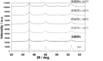
- FIG. 2 is an enlarged view of the high-angle side of the XRD of FIG. 1;
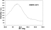
- FIG. 7 is a diagram showing the results of XRD of Example 3.
- x to y represents a numerical range of "x to y”.
- the upper and lower limits stated for numerical ranges can be combined arbitrarily.
- a positive electrode composite material as in this embodiment could not be manufactured using conventional techniques.
- a solid electrolyte when a solid electrolyte is added to a sulfur-carbon composite and mechanically mixed by applying strong energy, the crystallinity of the solid electrolyte decreases due to mechanical mixing, and the Li + conductivity decreases. , ionic resistance increases.
- heat treatment under specific temperature conditions can impart characteristic crystallinity to the solid electrolyte that contributes to lowering the ionic resistance.
- Such crystallinity may be imparted as a result of the generation of a new crystal phase with a slightly different lattice constant in addition to the original crystal phase.
- the half-width of the above-mentioned diffraction peak A becomes 0.25° or more, and preferably the left-right asymmetry parameter ⁇ ' of the later-described diffraction peak B becomes 1.50 ⁇ 10 4 or more. .
- Powder X-ray diffraction using CuK ⁇ rays is performed by the method described in Examples.
- the half-width of the diffraction peak A is a value obtained by subtracting the device constant, and is specifically calculated by the method described in Examples.
- the half width of the diffraction peak A is 0.25° or more, 0.26° or more, 0.27° or more, 0.28° or more, 0.29° or more, 0.30° or more, 0. .31° or more or 0.32° or more.
- the upper limit is not particularly limited, and is, for example, 2.0° or less.
- the left-right asymmetry parameter ⁇ ' of the diffraction peak B is 1.50 ⁇ 10 4 or more. Thereby, the effects of the present invention are more significantly exhibited.
- the left-right asymmetry parameter ⁇ ' of the diffraction peak B is calculated by the method described in Examples.
- the left-right asymmetry parameter ⁇ ' of the diffraction peak B is 1.50 ⁇ 10 4 or more, 2.00 ⁇ 10 4 or more, 3.00 ⁇ 10 4 or more, 4.00 ⁇ 10 4 or more, or 5. 00 ⁇ 10 4 or more.
- the upper limit is not particularly limited, and is, for example, 5.00 ⁇ 10 5 or less.
- Sulfur-based active materials are not particularly limited, but include sulfur, lithium sulfide (Li 2 S), lithium polysulfide (Li 2 S n :n satisfies 1 ⁇ n ⁇ 8), and titanium sulfide (TiS 2 ). , molybdenum sulfide (MoS 2 ), iron sulfide (FeS, FeS 2 ), copper sulfide (CuS), nickel sulfide (Ni 3 S 2 ), and sulfur-containing polymer compounds.
- Sulfur is not particularly limited, but sulfur with high purity is preferred. Specifically, the purity is preferably 95% by mass or more, more preferably 96% by mass or more, and particularly preferably 97% by mass or more.
- the crystalline system of sulfur include ⁇ sulfur (orthorhombic system), ⁇ (monoclinic system), ⁇ (monoclinic system), amorphous sulfur, and the like. These may be used alone or in combination of two or more.
- the solid electrolyte may include a solid electrolyte. Examples of such solid electrolytes include solid electrolytes having an argyrodite crystal structure.
- Examples of the argyrodite crystal structure include Li 7 PS 6 crystal structure; compositional formulas Li 7 -x P 1 -y Si y S 6 and Li 7+x P 1-y Si y S 6 having a structural skeleton of Li 7 PS 6 ; (x is -0.6 to 0.6, y is 0.1 to 0.6); Li 7-x-2y PS 6-x-y Cl x (0.8 ⁇ x ⁇ 1 .7, 0 ⁇ y ⁇ -0.25x+0.5); Li 7-x PS 6-x Ha x (Ha is Cl or Br, x is preferably 0.2 to 1.8); The crystal structure shown is exemplified.
- the half-width of the diffraction peak A is 0.25° or more.
- the left-right asymmetry parameter ⁇ ' of the diffraction peak B is 1.50 ⁇ 10 4 or more is satisfied. As described above, these conditions are met as a result of the generation of a new crystalline phase at a slightly shifted position in addition to the original crystalline phase by heat treatment under specific temperature conditions after mechanical mixing.
- the positive electrode mixture further includes a conductive additive.
- the conductive aid is a carbon material.
- the conductive aid which is a carbon material may be any material as long as it has electronic conductivity. It is preferable that the conductive aid has a plurality of pores. Particularly preferred is a carbon material having pores. Carbon materials have high conductivity and are lighter than other conductive materials, so they can increase the power density and capacity per unit weight of the battery.
- the specific surface area of the conductive additive is preferably 0.1 m 2 /g or more and 5000 m 2 /g or less, more preferably 1 m 2 /g or more and 4000 m 2 /g or less, and still more preferably 1 m 2 /g or more and 3000 m 2 /g. g or less, most preferably 10 m 2 /g or more and 3000 m 2 /g or less.
- the pore volume of the conductive aid is preferably 0.1 cc/g or more and 5.0 cc/g or less.
- the pores of the conductive additive preferably have an average diameter of 0.1 nm or more and 40 nm or less, more preferably 0.5 nm or more and 40 nm or less, still more preferably 0.5 nm or more and 20 nm or less, and most preferably 1 nm or more and 20 nm or less.
- the specific surface area, pore volume, and pore diameter of the conductive aid can be determined using a nitrogen adsorption isotherm obtained by adsorbing nitrogen gas to the conductive aid under liquid nitrogen temperature.
- the specific surface area can be calculated by the Brennauer-Emmet-Telle (BET) multi-point method using a nitrogen adsorption isotherm.
- the pore volume and pore diameter can be determined by the Barrett-Joyner-Halenda (BJH) method using a nitrogen adsorption isotherm.
- a specific surface area/pore distribution measuring device Autosorb-3 manufactured by Quantacrome can be used.
- carbon materials include, but are not limited to, carbon blacks such as Ketjen black, acetylene black, Denka black, thermal black, and channel black, mesoporous carbon, activated carbon, amorphous carbon, carbon nanotubes, and vapor grown carbon fiber (VGCF). , carbon nanohorns, fullerenes, carbon fibers, natural graphite, artificial graphite, graphene, graphene oxide, reduced graphene oxide, and the like. Further, these may be used alone or in combination of two or more. Moreover, these composite materials can also be used.
- carbon blacks such as Ketjen black, acetylene black, Denka black, thermal black, and channel black
- mesoporous carbon activated carbon
- amorphous carbon carbon nanotubes
- VGCF vapor grown carbon fiber
- carbon nanohorns fullerenes
- carbon fibers natural graphite, artificial graphite, graphene, graphene oxide, reduced graphene oxide, and the like. Further,
- Mesoporous carbon is a carbon material having two-dimensional or three-dimensional pores obtained by the production method described in the following documents: For example, S. J. Sang, S. H. Joo, R. Ryoo, et. , J. Am. Chem. Soc. , 122 (2000) 10712-10713, and T. Yokoi, Y. Sakamoto, O. Terasaki, et. , J. Am. Chem. Soc. , 128 (2006) 13664-13665
- the conductive aid has pores with a pore size of less than 5 nm. In one embodiment, the conductive aid does not have pores with a pore diameter of 5 nm or more. Note that the pore diameter is a value measured by a nitrogen adsorption/desorption measurement method. In one embodiment, the conductive additive includes one or more selected from the group consisting of activated carbon and carbon black. In one embodiment, the conductive aid does not include "a carbon replica having a three-dimensional honeycomb structure (closed cell structure) and having pores with a pore diameter of 5 nm or more and 20 nm or less".
- the positive electrode mixture may or may not contain components other than the sulfur-based active material, solid electrolyte, and conductive aid.
- Other components are not particularly limited, and include, for example, a binder, a solvent, a dispersant, and the like.
- the contents of the sulfur-based active material, solid electrolyte, and conductive additive are not particularly limited.
- the content of the sulfur-based active material is 40 to 350 parts by mass based on 100 parts by mass of the solid electrolyte.
- the mass ratio of the sulfur-based active material to the conductive additive is 10:90 to 95:5, preferably 30 to 70:90. ⁇ 10.
- substantially 100% by mass is the sulfur-based active material and the solid electrolyte, or the sulfur-based active material, the solid electrolyte, and the conductive aid. Note that in the case of “substantially 100% by mass”, unavoidable impurities may be included.
- the heating treatment includes obtaining a positive electrode composite material, and the temperature of the heat treatment is 160 to 280°C. According to the method for manufacturing a positive electrode composite material according to this embodiment, the ionic resistance of the resulting positive electrode composite material can be reduced.
- heat treatment at specific temperature conditions of 160 to 280° C. can impart characteristic crystallinity to the solid electrolyte that contributes to lowering ionic resistance.
- Such crystallinity may be imparted as a result of the generation of a new crystal phase with a slightly different lattice constant in addition to the original crystal phase.
- mixing devices used in mechanical mixing include planetary ball mills, rolling mills, bead mills, Filmics, Nauta mixers, tornado mixers, twin-screw extruders, multi-screw rollers, solid phase shear kneaders, and the like.
- the temperature of the heat treatment can be 160°C or higher, 165°C or higher, 170°C or higher, 175°C or higher, 180°C or higher, or 185°C or higher, and 280°C or lower, 270°C or lower, 260°C
- the temperature may be below 250°C, below 240°C, below 230°C, below 220°C, below 215°C, below 210°C, below 205°C, below 200°C or below 195°C.
- the temperature of the heat treatment is preferably close to 190° C. within the above-mentioned range.
- "X°C or less" means that heating is not performed at a temperature exceeding X°C.
- the time of the heat treatment is not particularly limited, it is preferable to heat for 30 minutes or more, 60 minutes or more, or 90 minutes or more in the above-mentioned temperature range.
- the upper limit is not particularly limited, and is, for example, 20 hours or less or 10 hours or less.
- use Examples of such a solid electrolyte include the solid electrolyte including the argyrodite crystal structure described for the positive electrode composite material according to one embodiment of the present invention.
- the method for producing a solid electrolyte having an argyrodite crystal structure is not particularly limited, and any known method can be employed.
- the raw material mixture is more preferably a combination of lithium sulfide, phosphorus sulfide, and lithium halide, and even more preferably a combination of Li 2 S, P 2 S 5 , and LiCl and/or LiBr.
- a solid electrolyte having an argyrodite crystal structure can be produced by thoroughly mixing the above raw material mixture in, for example, a mortar, a ball mill, a vibration mill, a tumbling mill, or a kneader, and then heat-treating the mixture. It is preferable to use a kneader for mixing since it can be performed continuously in a short time.
- the kneader is not particularly limited, but a multi-shaft kneader having two or more shafts is preferred. In this mixing, the raw material mixture may be reacted to form glass.
- the heat treatment temperature is preferably 350 to 480°C, more preferably 360 to 460°C, and particularly preferably 380 to 450°C.
- the heat treatment time varies depending on the composition and temperature, but may be adjusted within a range of, for example, 10 minutes or more and 48 hours or less.
- the atmosphere for the heat treatment is not particularly limited, but it is preferably not under a hydrogen sulfide stream but under an inert gas atmosphere such as nitrogen or argon.
- the shape of the solid electrolyte is not particularly limited, but may be, for example, particulate.
- the average particle size (D 50 ) of the particulate crystalline sulfide solid electrolyte is similar to the average particle size (D 50 ) of the amorphous sulfide solid electrolyte described above, for example, from 0.01 ⁇ m to 500 ⁇ m, 0. An example is a range of .1 to 200 ⁇ m.
- the sulfur-based active material to be subjected to mechanical mixing is complexed with a conductive additive in advance.
- a conductive additive those described for the positive electrode composite material according to one embodiment of the present invention can be used.
- the sulfur-based active material and the conductive additive can be composited by heating the sulfur-based active material together with the conductive additive before mechanical mixing. This heating temperature is not particularly limited, and is, for example, 120 to 350°C.
- the mass ratio of the sulfur-based active material to the conductive aid is 10:90 to 95:5, preferably 30:70 to 90:10.
- the positive electrode composite material manufactured by the method for manufacturing a positive electrode composite material according to this aspect is the positive electrode composite material according to one aspect of the present invention described above.
- Lithium Ion Battery includes the positive electrode composite material according to one embodiment of the present invention described above. According to the lithium ion battery according to this aspect, since the ionic resistance of the positive electrode mixture can be reduced, the effect of operating at low resistance can be obtained.
- the positive electrode mixture can be used as a positive electrode layer of a lithium ion battery.
- a negative electrode layer that does not contain lithium ions as the negative electrode active material can be selected.
- the negative electrode active material contained in the negative electrode layer of the lithium ion battery can be a "negative electrode active material containing lithium ions.”
- the negative electrode active material contained in the negative electrode layer of the lithium ion battery may be "a negative electrode active material that supplies lithium ions to the positive electrode.”
- the negative electrode of the lithium ion battery is not particularly limited as long as it can be used in normal batteries.
- the negative electrode may be made of a negative electrode mixture of a negative electrode active material and a solid electrolyte.
- the negative electrode active material commercially available materials can be used.
- carbon materials, Sn metals, In metals, Si metals, and alloys of these metals can be used.
- natural graphite various graphites, metal powders such as Si, Sn, Al, Sb, Zn, Bi, metal alloys such as SiAl, Sn 5 Cu 6 , Sn 2 Co, Sn 2 Fe, and other amorphous alloys.
- metal alloys such as SiAl, Sn 5 Cu 6 , Sn 2 Co, Sn 2 Fe, and other amorphous alloys. Examples include plated alloys.
- particle size There are no particular restrictions on the particle size, but particles with an average particle size of several ⁇ m to 80 ⁇ m can be suitably used.
- electrolyte layer there are no particular restrictions on the electrolyte layer, and known ones can be used.
- oxide-based solid electrolytes, sulfide-based solid electrolytes, and polymer-based electrolytes are preferred, and sulfide-based solid electrolytes are more preferred from the viewpoint of ionic conductivity.
- This sulfide-based solid electrolyte is preferably one used in the above-mentioned positive electrode mixture.
- the method for manufacturing a lithium ion battery is not particularly limited.
- Examples include a method of laminating and pressing.
- Example 1 Manufacture of positive electrode composite material (Example 1) (1) Preparation of Composite Powder A Activated carbon (MSC-30, manufactured by Kansai Thermochemical Co., Ltd.) and sulfur were placed in a glass bottle at a weight ratio of 3:7, and the mixture was sealed in a SUS tube container. The mixture was heated in an electric furnace at 150° C. for 6 hours and at 300° C. for 2.75 hours to obtain composite powder A of activated carbon and sulfur.
- MSC-30 Composite Powder A Activated carbon
- sulfur sulfur
- Example 2 A positive electrode composite material was obtained by the same procedure as in Example 1 except that the heating temperature of composite powder B was 160°C.
- Example 3 A positive electrode composite material was obtained in the same manner as in Example 1 except that the heating temperature of composite powder B was 200°C.
- Example 4 A positive electrode composite material was obtained in the same manner as in Example 1 except that the heating temperature of composite powder B was 220°C.
- Example 1 A positive electrode composite material was obtained by the same procedure as in Example 1 except that heating of composite powder B was omitted.
- Comparative example 2 A positive electrode composite material was obtained by the same procedure as in Example 1, except that the heating conditions for composite powder B were changed to 150° C. for 6 hours and then 300° C. for 2 hours and 45 minutes.
- ⁇ Tube voltage 30kV
- ⁇ Tube current 10mA
- ⁇ X-ray wavelength Cu-K ⁇ ray (1.5418 ⁇ )
- ⁇ Optical system Concentration method ⁇ Slit configuration: Solar slit 4° (both incident side and light receiving side), divergent slit 1mm, K ⁇ filter (Ni plate 0.5%), air scatter screen 3mm)
- the ratio (I peak /I bg ) related to diffraction peak A is preferably 1.250 or more, more preferably 1.300 or more.
- the ratio (I peak /I bg ) related to diffraction peak B is preferably 1.300 or more, more preferably 1.350 or more.
- the diffraction peak A has a ratio (I peak /I bg ) of 2.578, 2.629, 2.704, 2.838, respectively. Since it is 2.311, it is determined that it "exists", and the ratio (I peak /I bg ) of diffraction peak B is 3.287, 3.232, 3.370, 3.370, 2.688.
- the diffraction peak A is determined to be "absent” because the ratio (I peak /I bg ) is 1.108
- the diffraction peak B is determined to be "absent” because the ratio (I peak /I bg ) is 1.108.
- I bg ) was 1.198, so it was determined that it did not exist.
- w Half-width of the peak at 25.6 ⁇ 0.5° (diffraction peak A) obtained by measurement
- w half width obtained by measurement was determined as follows. A linear baseline was set for the peak shape obtained by the XRD measurement, and the difference between the intensity at each point and the baseline was taken to obtain an XRD curve.
- the peak with a larger ⁇ ' has a larger error when fitting with a symmetrical curve, that is, it can be said that it is a peak with high left-right asymmetry.
- ⁇ ' sum of errors/number of elements (number of plots at 44.38° ⁇ 46.05°)
- Ionic Resistance Measuring Cell 100 mg of the solid electrolyte B prepared by the above procedure was press-molded in a Macor cylinder having a diameter of 10 mm. 20 mg of positive electrode composite powder was placed on the pressurized surface and pressure molded again. An ionic resistance measurement cell was prepared by putting 20 mg of positive electrode mixture powder on the pressurized surface opposite to the positive electrode mixture and applying pressure.
- Table 1 shows the half-width of the diffraction peak A, the left-right asymmetry parameter ⁇ ' of the diffraction peak B, and the ionic resistance for each composite material. Further, FIG. 1 shows an XRD spectrum, and FIG. 2 shows an enlarged view of the high angle side of the XRD spectrum.
- Example 3 shows the results of XRD measurement of the positive electrode composite material obtained in Example 3 under the same conditions as in Patent Document 3. From FIG. 3, the crystal peak behavior (splitting method) of the positive electrode composite material obtained in Example 3 is the same as that of the positive electrode composite material described in Patent Document 3 (XRD spectrum of FIG. 1 described in Patent Document 3). It can be seen that there is a difference in crystal phase (this is thought to be the same in other examples).
- the positive electrode mixture of the present invention is suitable as a positive electrode for lithium ion batteries.
- the lithium ion battery of the present invention is suitably used in, for example, batteries used in information-related equipment and communication equipment such as personal computers, video cameras, and mobile phones, and vehicles such as electric cars.
Landscapes
- Chemical & Material Sciences (AREA)
- Electrochemistry (AREA)
- General Chemical & Material Sciences (AREA)
- Chemical Kinetics & Catalysis (AREA)
- Inorganic Chemistry (AREA)
- Engineering & Computer Science (AREA)
- Manufacturing & Machinery (AREA)
- Materials Engineering (AREA)
- Physics & Mathematics (AREA)
- Condensed Matter Physics & Semiconductors (AREA)
- General Physics & Mathematics (AREA)
- Secondary Cells (AREA)
- Battery Electrode And Active Subsutance (AREA)
Priority Applications (3)
| Application Number | Priority Date | Filing Date | Title |
|---|---|---|---|
| CN202380054930.2A CN119631190A (zh) | 2022-08-10 | 2023-08-02 | 正极复合材料、正极复合材料的制造方法以及锂离子电池 |
| KR1020257001291A KR20250047261A (ko) | 2022-08-10 | 2023-08-02 | 정극 합재, 정극 합재의 제조 방법 및 리튬 이온 전지 |
| JP2024540421A JPWO2024034499A1 (https=) | 2022-08-10 | 2023-08-02 |
Applications Claiming Priority (2)
| Application Number | Priority Date | Filing Date | Title |
|---|---|---|---|
| JP2022-127908 | 2022-08-10 | ||
| JP2022127908 | 2022-08-10 |
Publications (1)
| Publication Number | Publication Date |
|---|---|
| WO2024034499A1 true WO2024034499A1 (ja) | 2024-02-15 |
Family
ID=89851693
Family Applications (1)
| Application Number | Title | Priority Date | Filing Date |
|---|---|---|---|
| PCT/JP2023/028345 Ceased WO2024034499A1 (ja) | 2022-08-10 | 2023-08-02 | 正極合材、正極合材の製造方法及びリチウムイオン電池 |
Country Status (4)
| Country | Link |
|---|---|
| JP (1) | JPWO2024034499A1 (https=) |
| KR (1) | KR20250047261A (https=) |
| CN (1) | CN119631190A (https=) |
| WO (1) | WO2024034499A1 (https=) |
Cited By (3)
| Publication number | Priority date | Publication date | Assignee | Title |
|---|---|---|---|---|
| WO2025183200A1 (ja) * | 2024-02-28 | 2025-09-04 | 出光興産株式会社 | 正極合材、リチウムイオン電池及び正極合材の製造方法 |
| WO2026034190A1 (ja) * | 2024-08-05 | 2026-02-12 | 出光興産株式会社 | 正極合材 |
| WO2026034191A1 (ja) * | 2024-08-05 | 2026-02-12 | 出光興産株式会社 | 正極合材 |
Citations (1)
| Publication number | Priority date | Publication date | Assignee | Title |
|---|---|---|---|---|
| WO2022045302A1 (ja) * | 2020-08-28 | 2022-03-03 | 三井金属鉱業株式会社 | 活物質及びその製造方法、電極合剤並びに電池 |
Family Cites Families (3)
| Publication number | Priority date | Publication date | Assignee | Title |
|---|---|---|---|---|
| JP6243103B2 (ja) | 2012-06-29 | 2017-12-06 | 出光興産株式会社 | 正極合材 |
| JP7283657B2 (ja) | 2019-03-26 | 2023-05-30 | 東京電力ホールディングス株式会社 | 硫黄正極合材およびその製造方法、硫黄正極、リチウム硫黄固体電池 |
| CN116323478B (zh) | 2020-10-13 | 2025-09-02 | Agc株式会社 | 硫化物系固体电解质及其制造方法 |
-
2023
- 2023-08-02 CN CN202380054930.2A patent/CN119631190A/zh active Pending
- 2023-08-02 WO PCT/JP2023/028345 patent/WO2024034499A1/ja not_active Ceased
- 2023-08-02 KR KR1020257001291A patent/KR20250047261A/ko active Pending
- 2023-08-02 JP JP2024540421A patent/JPWO2024034499A1/ja active Pending
Patent Citations (1)
| Publication number | Priority date | Publication date | Assignee | Title |
|---|---|---|---|---|
| WO2022045302A1 (ja) * | 2020-08-28 | 2022-03-03 | 三井金属鉱業株式会社 | 活物質及びその製造方法、電極合剤並びに電池 |
Cited By (3)
| Publication number | Priority date | Publication date | Assignee | Title |
|---|---|---|---|---|
| WO2025183200A1 (ja) * | 2024-02-28 | 2025-09-04 | 出光興産株式会社 | 正極合材、リチウムイオン電池及び正極合材の製造方法 |
| WO2026034190A1 (ja) * | 2024-08-05 | 2026-02-12 | 出光興産株式会社 | 正極合材 |
| WO2026034191A1 (ja) * | 2024-08-05 | 2026-02-12 | 出光興産株式会社 | 正極合材 |
Also Published As
| Publication number | Publication date |
|---|---|
| JPWO2024034499A1 (https=) | 2024-02-15 |
| CN119631190A (zh) | 2025-03-14 |
| KR20250047261A (ko) | 2025-04-03 |
Similar Documents
| Publication | Publication Date | Title |
|---|---|---|
| Puthusseri et al. | Conversion-type anode materials for alkali-ion batteries: State of the art and possible research directions | |
| WO2024034499A1 (ja) | 正極合材、正極合材の製造方法及びリチウムイオン電池 | |
| CN109417194B (zh) | 锂二次电池用硫化物系固体电解质 | |
| Wang et al. | Self-combustion synthesis of Na3V2 (PO4) 3 nanoparticles coated with carbon shell as cathode materials for sodium-ion batteries | |
| Li et al. | Electrochemical lithium storage performance of molten salt derived V2SnC MAX phase | |
| Xu et al. | A high performance all-vanadate-based Li-ion full cell | |
| Wang et al. | Facile Synthesis of Carbon‐Coated Li3VO4 Anode Material and its Application in Full Cells | |
| KR20080095909A (ko) | 카본 서브플루오라이드의 전기화학 | |
| Shin et al. | Sulfur/graphitic hollow carbon sphere nano-composite as a cathode material for high-power lithium-sulfur battery | |
| Wang et al. | Synergic antimony–niobium pentoxide nanomeshes for high-rate sodium storage | |
| CN113937347A (zh) | 氧化物、其制备方法、包括氧化物的固体电解质和包括氧化物的电化学装置 | |
| Li et al. | Ga 2 O 3–Li 3 VO 4/NC nanofibers toward superb high-capacity and high-rate Li-ion storage | |
| Subhan et al. | Effects of activated carbon treatment on Li4Ti5O12 anode material synthesis for lithium-ion batteries | |
| Kawade et al. | Synergic effects of the decoration of nickel oxide nanoparticles on silicon for enhanced electrochemical performance in LIBs | |
| Nam et al. | Silicon disulfide for high-performance Li-ion batteries and solid-state electrolytes | |
| Xu et al. | In-situ preparation of mesoporous carbon contained graphite-zinc quantum dots for enhancing the electrochemical performance of LiFePO4 | |
| Hill et al. | High surface area templated LiFePO 4 from a single source precursor molecule | |
| He et al. | Gas-expansion strategy for synchronizing high-rate and ultra-stable sodium storage of Fe7S8@ NSC anode | |
| WO2024195788A1 (ja) | 複合体、正極合材、リチウムイオン電池用正極、リチウムイオン電池、複合体の製造方法、活性炭の使用及び活性炭の製造方法 | |
| WO2024166908A1 (ja) | 活物質、固体電解質、電極合剤並びに電池 | |
| WO2024048476A1 (ja) | 複合材料の製造方法及び複合材料 | |
| JP7529968B2 (ja) | 固体電解質材料、その製造方法及び電池 | |
| Kim et al. | A scalable and flexible hybrid solid electrolyte based on NASICON-structure Li3Zr2Si2PO12 for high-voltage hybrid batteries | |
| Kim et al. | Impact of glucose on the electrochemical performance of nano-LiCoPO4 cathode for Li-ion batteries | |
| EP4579793A1 (en) | Positive electrode mixture, method for manufacturing positive electrode mixture, and lithium-ion battery |
Legal Events
| Date | Code | Title | Description |
|---|---|---|---|
| 121 | Ep: the epo has been informed by wipo that ep was designated in this application |
Ref document number: 23852466 Country of ref document: EP Kind code of ref document: A1 |
|
| WWE | Wipo information: entry into national phase |
Ref document number: 2024540421 Country of ref document: JP |
|
| WWE | Wipo information: entry into national phase |
Ref document number: 202380054930.2 Country of ref document: CN |
|
| NENP | Non-entry into the national phase |
Ref country code: DE |
|
| WWP | Wipo information: published in national office |
Ref document number: 202380054930.2 Country of ref document: CN |
|
| WWP | Wipo information: published in national office |
Ref document number: 1020257001291 Country of ref document: KR |
|
| 122 | Ep: pct application non-entry in european phase |
Ref document number: 23852466 Country of ref document: EP Kind code of ref document: A1 |