WO2024034491A1 - 煙検知装置 - Google Patents
煙検知装置 Download PDFInfo
- Publication number
- WO2024034491A1 WO2024034491A1 PCT/JP2023/028272 JP2023028272W WO2024034491A1 WO 2024034491 A1 WO2024034491 A1 WO 2024034491A1 JP 2023028272 W JP2023028272 W JP 2023028272W WO 2024034491 A1 WO2024034491 A1 WO 2024034491A1
- Authority
- WO
- WIPO (PCT)
- Prior art keywords
- light
- axis
- light receiving
- section
- detection device
- Prior art date
- Legal status (The legal status is an assumption and is not a legal conclusion. Google has not performed a legal analysis and makes no representation as to the accuracy of the status listed.)
- Ceased
Links
Images







Classifications
-
- G—PHYSICS
- G01—MEASURING; TESTING
- G01N—INVESTIGATING OR ANALYSING MATERIALS BY DETERMINING THEIR CHEMICAL OR PHYSICAL PROPERTIES
- G01N21/00—Investigating or analysing materials by the use of optical means, i.e. using sub-millimetre waves, infrared, visible or ultraviolet light
- G01N21/17—Systems in which incident light is modified in accordance with the properties of the material investigated
- G01N21/47—Scattering, i.e. diffuse reflection
- G01N21/49—Scattering, i.e. diffuse reflection within a body or fluid
- G01N21/53—Scattering, i.e. diffuse reflection within a body or fluid within a flowing fluid, e.g. smoke
-
- G—PHYSICS
- G08—SIGNALLING
- G08B—SIGNALLING SYSTEMS, e.g. PERSONAL CALLING SYSTEMS; ORDER TELEGRAPHS; ALARM SYSTEMS
- G08B17/00—Fire alarms; Alarms responsive to explosion
- G08B17/10—Actuation by presence of smoke or gases, e.g. automatic alarm devices for analysing flowing fluid materials by the use of optical means
- G08B17/103—Actuation by presence of smoke or gases, e.g. automatic alarm devices for analysing flowing fluid materials by the use of optical means using a light emitting and receiving device
- G08B17/107—Actuation by presence of smoke or gases, e.g. automatic alarm devices for analysing flowing fluid materials by the use of optical means using a light emitting and receiving device for detecting light-scattering due to smoke
Definitions
- the present invention relates to a device for detecting smoke.
- a smoke detection device that detects the occurrence of smoke in a monitored space by detecting smoke contained in the monitored space.
- One type of smoke detection device is a type called a photoelectric type.
- a photoelectric smoke detection device generates smoke particles when the light emitting part is reflected by smoke particles in the air flowing from the outside into a container that houses the light emitting part and the light receiving part. Smoke detection is performed based on the signal.
- Another type of photoelectric smoke detection device is a type called a two-light receiving type.
- polarized light is emitted from a light emitting part in the direction of the light emitting axis, and based on signals generated by two light receiving parts having light receiving axes that intersect with the light emitting axis from different directions, it detects light in the air.
- Patent Document 1 An example of a patent document disclosing a two-light receiving type smoke detection device is Patent Document 1.
- FIG. 11 is a diagram schematically showing the configuration of a two-light receiving type smoke detection device 9 according to the prior art.
- FIG. 11(A) is a plan view of the smoke detection device 9 with the lid of the container removed.
- FIG. 11(B) is a cross-sectional view of the smoke detection device 9 shown by a broken line in FIG. 11(A) as viewed in the direction of arrow A.
- FIG. 11(B) shows a cross section of the smoke detection device 9 with the lid of the container attached.
- the smoke detection device 9 includes an electronic circuit board 91 for a light emitting part, an electronic circuit board 92 for a first light receiving part, an electronic circuit board 93 for a second light receiving part, a light emitting part 94, a first light receiving part 95, a second light receiving part 96, A processor 97 and a container 98 are provided.
- the electronic circuit board 91 for the light emitting section is an electronic circuit board arranged to stand up perpendicularly to a horizontal plane.
- a light emitting section 94 is arranged on the electronic circuit board 91 for the light emitting section.
- the first light-receiving unit electronic circuit board 92 is an electronic circuit board arranged on a plane that is inclined with respect to the horizontal plane.
- a first light receiving section 95 and a processor 97 are arranged on the first light receiving section electronic circuit board 92 .
- the second light-receiving section electronic circuit board 93 is an electronic circuit board arranged to stand up perpendicularly to the horizontal plane.
- a second light receiving section 96 is arranged on the second light receiving section electronic circuit board 93 .
- the processor 97 may be arranged on an electronic circuit board other than the first light-receiving part electronic circuit board 92 (for example, the light-emitting part electronic circuit board 91 or the second light-receiving part electronic circuit board 93).
- the light emitting unit 94 emits polarized light in the direction of a light emitting axis (hereinafter referred to as "light emitting axis B") indicated by arrow B in FIG.
- a light emitting axis hereinafter referred to as "light emitting axis B”
- the direction of the straight line is perpendicular to the horizontal plane
- the polarized light emitted from the light emitting section 94 is elliptically polarized light
- the direction of the long axis of the ellipse is the horizontal plane. perpendicular to .
- the first light receiving unit 95 receives light directed in the direction of a first light receiving axis (hereinafter referred to as "first light receiving axis C") indicated by arrow C in FIG. 11(B), and indicates the intensity of the received light. Generate a signal.
- the first light-receiving axis C intersects the light-emitting axis B at a predetermined angle within a vertical plane (a plane perpendicular to the horizontal plane) that includes the light-emitting axis B.
- the first light-receiving unit electronic circuit board 92 is arranged at a position perpendicular to the first light-receiving axis C.
- the second light receiving section 96 receives light directed toward a second light receiving axis (hereinafter referred to as "second light receiving axis D") indicated by arrow D in FIG. 11(A), and indicates the intensity of the received light. Generate a signal.
- the second light-receiving axis D is an axis in a different direction from the first light-receiving axis C, and intersects the light-emitting axis B at a predetermined angle within a horizontal plane that includes the light-emitting axis B.
- angle between the light emitting axis B and the first light receiving axis C and the angle between the light emitting axis B and the second light receiving axis D may be the same or different.
- the processor 97 is an arithmetic device that processes data, and processes a signal generated by the first light receiving section 95 when the light emitting section 94 emits light and a signal generated by the second light receiving section 96 when the light emitting section 94 emits light. Based on this, it plays the role of a smoke determination unit that determines the type of smoke in the air. For example, the processor 97 determines the ratio of the amplitude value of the signal generated by the second light receiving section 96 when the light emitting section 94 emits light to the amplitude value of the signal generated by the first light receiving section 95 when the light emitting section 94 emits light. The type of smoke in the air flowing into the container 98 from the outside of the container 98 is determined based on the comparison result between the above and a predetermined threshold value.
- the container 98 accommodates the components of the smoke detection device 9 including the light emitting section 94, the first light receiving section 95, and the second light receiving section 96.
- the container 98 has an inlet H1 for air flowing in from the outside and an outlet H2 for air flowing out to the outside.
- the electronic circuit board 92 for the first light receiving section is arranged so as to be inclined with respect to the horizontal plane, and the electronic circuit board 93 for the second light receiving section is arranged so as to stand up with respect to the horizontal plane. Because of this arrangement, the length in the vertical direction (vertical direction in FIG. 11(B)) becomes longer, and the size of the smoke detection device 9 becomes larger.
- the present invention provides a two-light receiving type smoke detection device that is easier to downsize compared to the conventional technology.
- the present invention provides a light emitting section that emits light, a first light receiving section having a first light receiving axis that intersects with a light emitting axis of the light emitting section, and a first light receiving section in which the first light receiving section is arranged.
- a first electronic circuit board a first electronic circuit board; a second light receiving section having a second light receiving axis that intersects with the light emitting axis of the light emitting section and in a direction different from the first light receiving axis; and a second electronic circuit in which the second light receiving section is arranged.
- the present invention proposes a smoke detection device including a smoke determination section, wherein the first light receiving axis is inclined with respect to the vertical direction of the first electronic circuit board.
- the two-light receiving type smoke detection device according to the present invention can be easily miniaturized compared to the two-light receiving type smoke detection device according to the prior art.
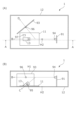
- FIG. 1 is a diagram schematically showing the configuration of a smoke detection device according to an embodiment.
- FIG. 2 is an external view of a light shielding member according to an embodiment.
- FIG. 2 is a cross-sectional view of a light shielding member according to an embodiment.
- FIG. 7 is an external view of a light shielding member according to a modified example.
- FIG. 7 is an external view of a light shielding member according to a modified example.
- FIG. 7 is an external view of a light shielding member according to a modified example.
- FIG. 7 is an external view of a light shielding member according to a modified example.
- FIG. 7 is a diagram schematically showing the configuration of a smoke detection device that is compared to a smoke detection device according to a modified example.
- FIG. 3 is a diagram schematically showing the configuration of a smoke detection device according to a modified example.
- FIG. 3 is a diagram schematically showing the configuration of a smoke detection device according to a modified example.
- 1 is a diagram schematically showing the configuration of a smoke detection device according to a prior art.
- the smoke detection device 1 includes components common to the smoke detection device 9 according to the prior art. Therefore, the differences between the smoke detection device 1 and the smoke detection device 9 will be explained below, and the explanation of the common points will be omitted. Moreover, in the following description, the same reference numerals as those used in the smoke detection device 9 are used for components that are common to the components included in the smoke detection device 9 among the components included in the smoke detection device 1.
- FIG. 1 is a diagram schematically showing the configuration of a smoke detection device 1. However, in FIG. 1, illustration of components not related to the features of the present invention is omitted.
- FIG. 1(A) is a plan view of the smoke detection device 1 with the lid of the container removed.
- FIG. 1(B) is a view of the cross section indicated by the broken line in FIG. 1(A) as viewed in the direction of arrow A. However, FIG. 1(B) shows a cross section of the smoke detection device 1 with the lid of the container attached.
- the smoke detection device 1 includes a light emitting section electronic circuit board 91, a second light receiving section electronic circuit board 93 (an example of a second electronic circuit board), a light emitting section 94, It includes a first light receiving section 95, a second light receiving section 96, and a processor 97.
- the smoke detection device 1 includes a first light receiving section electronic circuit board 11 (an example of a first electronic circuit board) in place of the first light receiving section electronic circuit board 92 included in the smoke detection device 9.
- the first light receiving unit electronic circuit board 11 is arranged substantially parallel to the horizontal plane. That is, the light emitting axis B of the first light receiving part electronic circuit board 11 and the light emitting part 94 are substantially parallel. Note that in the present application, “substantially” means "when unintended errors by the manufacturer are not taken into account.”
- the smoke detection device 1 includes a container 12 instead of the container 98 included in the smoke detection device 9.
- the container 12 has a shorter vertical length than the container 98.
- the reason why the container 12 can have a shorter vertical length than the container 98 is because the first light receiving section electronic circuit board 11 is not inclined with respect to the horizontal plane.
- the container 12 has an inlet H1 and an outlet H2.
- the smoke detection device 1 includes a light shielding member 13 that the smoke detection device 9 does not include.
- the light shielding member 13 is a light shielding member disposed so as to surround the first light receiving section 95 .
- the light blocking member 13 blocks light directed toward the first light receiving section 95 in a direction intersecting the first light receiving axis C.
- the light that is blocked by the light shielding member 13 includes light that is emitted from the light emitting section 94, deviates from the light emitting axis B, and heads toward the first light receiving section 95, and light that is emitted from the light emitting section 94, is reflected within the container 12, and is directed to the first light receiving section 95. Light directed toward the light receiving section 95 is included.
- the light shielding member 13 serves to reduce the influence of such light on the determination of the presence or absence of smoke and the determination of the type of smoke. Moreover, the light shielding member 13 also serves as a mounting member for arranging the first light receiving section 95 at a predetermined angle with respect to the electronic circuit board 11 for the first light receiving section.
- FIG. 2 is an external view of the light shielding member 13.
- 2(A) is a diagram of the light shielding member 13 seen from above
- FIG. 2(B) is a diagram of the light shielding member 13 seen from the right side to the left in FIG. 1(B)
- FIG. 2(C) is a diagram of the light shielding member 13
- FIG. 2 is a diagram seen from the left side of FIG. 1(B) to the right.
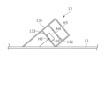
- FIG. 3 is a sectional view of the light shielding member 13.
- the light-shielding member 13 includes a light-shielding box 131 that is a component visible from the outside, a diaphragm plate 132 arranged inside the light-shielding box 131, and a light-receiving unit arrangement plate 133 arranged inside the light-shielding box 131.
- the light-shielding box 131 has a structure in which a rectangular cylinder is cut diagonally, the upper surface is closed, and an opening H3 is provided on the upper surface.
- the aperture H3 is located on the first light receiving axis C.
- the shape of the light-shielding box 131 is not limited to that shown in FIG. 2 as long as it is a hollow light-shielding member that accommodates the first light-receiving section 95 and has an opening H3 on the first light-receiving axis C.
- the light shielding box 131 may have a structure in which a cylinder is cut diagonally, the top surface is closed, and an opening H3 is provided in the top surface.
- the aperture plate 132 is a plate-shaped light shielding member that is housed in the light shielding box 131, is substantially perpendicular to the first light receiving axis C, and has a hole H4 on the first light receiving axis C.
- the aperture plate 132 blocks the light that has entered the light-shielding box 131 through the opening H3 in the direction intersecting the first light-receiving axis C so that the light does not reach the first light-receiving section 95.
- the number of aperture plates 132 is one, but the light shielding member 13 may have a plurality of aperture plates 132 arranged in parallel. Further, if sufficient light shielding is achieved only with the light shielding box 131, the light shielding member 13 does not need to have the aperture plate 132.
- the light-receiving unit arrangement plate 133 is housed in the light-shielding box 131, is substantially perpendicular to the first light-receiving axis C, and is arranged on the back side of the aperture plate 132 (closer to the first light-receiving unit electronic circuit board 11). , is a plate-shaped member on which the first light receiving section 95 is attached.
- the light receiving unit arrangement plate 133 is provided with a hole H5 through which the connection terminal (lead) of the first light receiving unit 95 passes.
- the shape of the hole H5 may be either a cylindrical shape, a prismatic shape, or the like.
- the number of holes H5 may be 1 or 2 or more depending on the number and position of the connection terminals of the first light receiving section 95.
- the first light receiving section 95 is arranged above the light receiving section arrangement plate 133, and its connection terminal passes through the hole H5 of the light receiving section arrangement plate 133 and connects to the electronic circuit board for the first light receiving section on the lower side. 11. That is, the first light receiving section 95 is arranged on the first light receiving section electronic circuit board 11 via the light shielding member 13.
- the first light receiving axis C is inclined with respect to the vertical direction (vertical direction) of the first light receiving part electronic circuit board 11. Therefore, the length of the container 12 of the smoke detection device 1 in the vertical direction can be shortened compared to the container 98 of the smoke detection device 9. As a result, the smoke detection device 1 is easier to downsize than the smoke detection device 9.
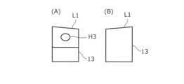
- the edge portion of the light shielding box 131 closest to the light emitting axis B is It may also have a chamfered shape.
- the chamfered shape of the light-shielding box 131 is not limited to that formed by chamfering, and may be formed into a chamfered shape when the light-shielding box 131 is molded, for example. Further, the type of chamfer of the light shielding box 131 may be either C chamfer or R chamfer (fillet).
- FIG. 4 is a diagram of the light shielding member 13 according to this modification as viewed from the front of FIG. 1(B). A portion of the light shielding member 13 indicated by a broken circle in FIG. 4 has a chamfered shape.
- Modification 3 In order to shorten the vertical length of the smoke detection device 1 and to reduce the probability that the light emitted from the light emitting part 94 is reflected by the light shielding member 13, the edge portion of the light shielding box 131 closest to the light emission axis B is A recess may be provided.
- FIG. 5 shows the light shielding member 13 according to this modification as viewed from above (FIG. 5(A)), as viewed from the right side to the left in FIG. 1(B) (FIG. 5(B)), and , is a diagram (FIG. 5(C)) seen from the left side of FIG. 1(B) to the right.
- a recess R1 is provided in the light shielding box 131 of the light shielding member 13 according to this modification. Note that a hole may be formed in the light shielding box 131 by the recess R1.
- FIG. 6 shows an example of the light shielding member 13 according to this modification as viewed from the right side to the left in FIG. 1(B) (FIG. 6(A)), and from the left side to the right in FIG. 1(B). (FIG. 6(B)).
- FIG. 7 shows another example of the light shielding member 13 according to this modification as viewed from the right side of FIG. 1(B) to the left direction (FIG. 7(A)) and FIG. 7B is a diagram viewed from the left to the right (FIG. 7(B)).
- the smoke detection device 1 when water droplets adhere to the surface of the light shielding member 13 due to dew condensation, the water droplets attached to the ridge line L1 of the light shielding box 131 that is closest to the light emitting axis B among the light shielding boxes 131 are Due to the slope of L1, it tends to flow down due to its own weight. Therefore, the probability that the light emitted from the light emitting section 94 is reflected by water droplets is reduced.
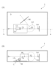
- FIG. 8 shows a smoke detection device 1 (smoke detection device compared to the smoke detection device according to this modification) in a case where a part of the light shielding box 131 is arranged within the light receiving area A1 of the second light receiving section 96.
- FIG. 9 is a diagram schematically showing the configuration of the smoke detection device 1 when the light-shielding box 131 is arranged outside the light-receiving area A2 of the second light-receiving section 96.
- the smoke detection device 1 having the configuration shown in FIG. 9 has a higher probability of detecting smoke and determining the type of detected smoke with higher accuracy than the smoke detection device 1 having the configuration shown in FIG. 8, and is therefore desirable.
- the second light receiving section 96 is placed closer to the light emitting section 94 than the example of FIG.
- the intersection P1 between the light emitting axis B and the first light receiving axis C is substantially different from the intersection P2 between the light emitting axis B and the second light receiving axis D.
- the second light receiving section 96 is arranged closer to the light emitting section 94 compared to the example of FIG.
- the light receiving section 95 may be arranged at a position apart from the light emitting section 94.
- FIG. 10 is a diagram schematically showing a cross section of a smoke detection device 1 according to this modification.
- the container 12 is provided with a hole through which a connection terminal of an electronic component that is housed in the container 12 and connected to the first light receiving section electronic circuit board 11 is passed.
- a hole H6 through which the connection terminal of the first light receiving section 95 is passed is shown.
- the first light receiving section 95 is arranged on the first light receiving section electronic circuit board 11 via the light shielding member 13 and the container 12.
- electronic components that are not housed in the container 12 can be placed on the first light receiving section electronic circuit board 11.
- the electronic component 14 and the electronic component 15 shown in FIG. 10 are examples of these electronic components.
- the degree of freedom in the position and size of the electronic components arranged on the first light receiving section electronic circuit board 11 is increased.
- electronic components not housed in the container 12 can be easily attached to the first light receiving section electronic circuit board 11.
- the smoke detection device 1 is arranged to surround the second light receiving section 96, and blocks light directed toward the second light receiving section 96 in a direction intersecting the second light receiving axis D.
- a light shielding member may be provided.
- the light emitting section 94 emits polarized light, but the light emitting section 94 may emit non-polarized light.
- the intersection P1 of the light-emitting axis B and the first light-receiving axis C when the intersection P2 of the light-emitting axis B and the second light-receiving axis D is different, or when only one of the first light-receiving section 95 and the second light-receiving section 96 is surrounded by a light-shielding member, the first If the light receiving conditions of the light receiving section 95 and the light receiving conditions of the second light receiving section 96 are different, the intensity of the light indicated by the signal generated by the first light receiving section 95 and the light indicated
Landscapes
- Analytical Chemistry (AREA)
- General Physics & Mathematics (AREA)
- Physics & Mathematics (AREA)
- Chemical & Material Sciences (AREA)
- General Health & Medical Sciences (AREA)
- Biochemistry (AREA)
- Life Sciences & Earth Sciences (AREA)
- Health & Medical Sciences (AREA)
- Immunology (AREA)
- Pathology (AREA)
- Business, Economics & Management (AREA)
- Emergency Management (AREA)
- Fire-Detection Mechanisms (AREA)
- Investigating Or Analysing Materials By Optical Means (AREA)
Priority Applications (2)
| Application Number | Priority Date | Filing Date | Title |
|---|---|---|---|
| CN202380056899.6A CN119698645A (zh) | 2022-08-12 | 2023-08-02 | 烟检测装置 |
| JP2024540418A JP7738765B2 (ja) | 2022-08-12 | 2023-08-02 | 煙検知装置 |
Applications Claiming Priority (2)
| Application Number | Priority Date | Filing Date | Title |
|---|---|---|---|
| JP2022-128804 | 2022-08-12 | ||
| JP2022128804 | 2022-08-12 |
Publications (1)
| Publication Number | Publication Date |
|---|---|
| WO2024034491A1 true WO2024034491A1 (ja) | 2024-02-15 |
Family
ID=89851582
Family Applications (1)
| Application Number | Title | Priority Date | Filing Date |
|---|---|---|---|
| PCT/JP2023/028272 Ceased WO2024034491A1 (ja) | 2022-08-12 | 2023-08-02 | 煙検知装置 |
Country Status (4)
| Country | Link |
|---|---|
| JP (1) | JP7738765B2 (https=) |
| CN (1) | CN119698645A (https=) |
| TW (1) | TW202424913A (https=) |
| WO (1) | WO2024034491A1 (https=) |
Citations (7)
| Publication number | Priority date | Publication date | Assignee | Title |
|---|---|---|---|---|
| JP2011203892A (ja) * | 2010-03-25 | 2011-10-13 | Nohmi Bosai Ltd | 煙感知器 |
| JP2011242909A (ja) * | 2010-05-17 | 2011-12-01 | Hochiki Corp | 高感度煙感知器 |
| JP2013020296A (ja) * | 2011-07-07 | 2013-01-31 | Hochiki Corp | 感知器 |
| JP2015191462A (ja) * | 2014-03-28 | 2015-11-02 | 能美防災株式会社 | 煙感知器 |
| JP2016090349A (ja) * | 2014-10-31 | 2016-05-23 | パナソニックIpマネジメント株式会社 | 粒子検出センサ、ダストセンサ、煙感知器、空気清浄機、換気扇及びエアコン |
| JP2019046112A (ja) * | 2017-08-31 | 2019-03-22 | ホーチキ株式会社 | 散乱光式感知器 |
| JP2020181507A (ja) * | 2019-04-26 | 2020-11-05 | 能美防災株式会社 | 煙感知器 |
Family Cites Families (2)
| Publication number | Priority date | Publication date | Assignee | Title |
|---|---|---|---|---|
| CN119096278A (zh) | 2022-04-27 | 2024-12-06 | 能美防灾株式会社 | 烟检测装置 |
| TW202409985A (zh) | 2022-06-09 | 2024-03-01 | 日商能美防災股份有限公司 | 煙檢測裝置 |
-
2023
- 2023-08-02 WO PCT/JP2023/028272 patent/WO2024034491A1/ja not_active Ceased
- 2023-08-02 JP JP2024540418A patent/JP7738765B2/ja active Active
- 2023-08-02 CN CN202380056899.6A patent/CN119698645A/zh active Pending
- 2023-08-08 TW TW112129663A patent/TW202424913A/zh unknown
Patent Citations (7)
| Publication number | Priority date | Publication date | Assignee | Title |
|---|---|---|---|---|
| JP2011203892A (ja) * | 2010-03-25 | 2011-10-13 | Nohmi Bosai Ltd | 煙感知器 |
| JP2011242909A (ja) * | 2010-05-17 | 2011-12-01 | Hochiki Corp | 高感度煙感知器 |
| JP2013020296A (ja) * | 2011-07-07 | 2013-01-31 | Hochiki Corp | 感知器 |
| JP2015191462A (ja) * | 2014-03-28 | 2015-11-02 | 能美防災株式会社 | 煙感知器 |
| JP2016090349A (ja) * | 2014-10-31 | 2016-05-23 | パナソニックIpマネジメント株式会社 | 粒子検出センサ、ダストセンサ、煙感知器、空気清浄機、換気扇及びエアコン |
| JP2019046112A (ja) * | 2017-08-31 | 2019-03-22 | ホーチキ株式会社 | 散乱光式感知器 |
| JP2020181507A (ja) * | 2019-04-26 | 2020-11-05 | 能美防災株式会社 | 煙感知器 |
Also Published As
| Publication number | Publication date |
|---|---|
| TW202424913A (zh) | 2024-06-16 |
| JP7738765B2 (ja) | 2025-09-12 |
| CN119698645A (zh) | 2025-03-25 |
| JPWO2024034491A1 (https=) | 2024-02-15 |
Similar Documents
| Publication | Publication Date | Title |
|---|---|---|
| US9134224B2 (en) | Gas component detection device | |
| AU664027B2 (en) | Photoelectric smoke detector | |
| JP2007147613A (ja) | ガスセンサアレー | |
| WO2014136414A1 (ja) | デバイス | |
| JP2008051764A (ja) | 測距センサ、及びその測距センサを搭載した電子機器 | |
| US5670947A (en) | Light scattering smoke sensor | |
| US20240027191A1 (en) | Optical Triangulation Sensor | |
| US20120218766A1 (en) | Light signal transmitter and light receiver for an optical sensor | |
| WO2024034491A1 (ja) | 煙検知装置 | |
| JP2019160680A (ja) | 光電センサ | |
| WO2012140482A1 (ja) | 気体成分検出装置 | |
| KR102933520B1 (ko) | 입자 검출 센서 및 입자 검출 장치 | |
| WO2021032942A1 (en) | Optical smoke detector | |
| JP2020041935A (ja) | トナー付着量センサ | |
| CN115825921A (zh) | 光学感应器及激光雷达 | |
| CN209992346U (zh) | 激光粉尘传感器 | |
| CN1763561B (zh) | 光电探测器 | |
| JP7157557B2 (ja) | 煙感知器 | |
| JP2006236848A (ja) | 反射型光電スイッチ用センサヘッド | |
| JP7329116B2 (ja) | 煙感知器 | |
| JPH082899Y2 (ja) | 光電検出装置 | |
| JPH0972727A (ja) | 光学センサ装置 | |
| JP2023076120A (ja) | 光電センサ | |
| KR102700596B1 (ko) | 광전자 장치 | |
| JP6598556B2 (ja) | 光電センサ |
Legal Events
| Date | Code | Title | Description |
|---|---|---|---|
| 121 | Ep: the epo has been informed by wipo that ep was designated in this application |
Ref document number: 23852458 Country of ref document: EP Kind code of ref document: A1 |
|
| WWE | Wipo information: entry into national phase |
Ref document number: 2024540418 Country of ref document: JP |
|
| WWE | Wipo information: entry into national phase |
Ref document number: 202380056899.6 Country of ref document: CN |
|
| NENP | Non-entry into the national phase |
Ref country code: DE |
|
| WWP | Wipo information: published in national office |
Ref document number: 202380056899.6 Country of ref document: CN |
|
| 122 | Ep: pct application non-entry in european phase |
Ref document number: 23852458 Country of ref document: EP Kind code of ref document: A1 |