WO2024034403A1 - 蓄電モジュール - Google Patents
蓄電モジュール Download PDFInfo
- Publication number
- WO2024034403A1 WO2024034403A1 PCT/JP2023/027384 JP2023027384W WO2024034403A1 WO 2024034403 A1 WO2024034403 A1 WO 2024034403A1 JP 2023027384 W JP2023027384 W JP 2023027384W WO 2024034403 A1 WO2024034403 A1 WO 2024034403A1
- Authority
- WO
- WIPO (PCT)
- Prior art keywords
- end surface
- inner edge
- storage module
- resin
- sealing
- Prior art date
- Legal status (The legal status is an assumption and is not a legal conclusion. Google has not performed a legal analysis and makes no representation as to the accuracy of the status listed.)
- Ceased
Links
Images



Classifications
-
- H—ELECTRICITY
- H01—ELECTRIC ELEMENTS
- H01G—CAPACITORS; CAPACITORS, RECTIFIERS, DETECTORS, SWITCHING DEVICES, LIGHT-SENSITIVE OR TEMPERATURE-SENSITIVE DEVICES OF THE ELECTROLYTIC TYPE
- H01G11/00—Hybrid capacitors, i.e. capacitors having different positive and negative electrodes; Electric double-layer [EDL] capacitors; Processes for the manufacture thereof or of parts thereof
- H01G11/10—Multiple hybrid or EDL capacitors, e.g. arrays or modules
- H01G11/12—Stacked hybrid or EDL capacitors
-
- H—ELECTRICITY
- H01—ELECTRIC ELEMENTS
- H01G—CAPACITORS; CAPACITORS, RECTIFIERS, DETECTORS, SWITCHING DEVICES, LIGHT-SENSITIVE OR TEMPERATURE-SENSITIVE DEVICES OF THE ELECTROLYTIC TYPE
- H01G11/00—Hybrid capacitors, i.e. capacitors having different positive and negative electrodes; Electric double-layer [EDL] capacitors; Processes for the manufacture thereof or of parts thereof
- H01G11/78—Cases; Housings; Encapsulations; Mountings
-
- H—ELECTRICITY
- H01—ELECTRIC ELEMENTS
- H01G—CAPACITORS; CAPACITORS, RECTIFIERS, DETECTORS, SWITCHING DEVICES, LIGHT-SENSITIVE OR TEMPERATURE-SENSITIVE DEVICES OF THE ELECTROLYTIC TYPE
- H01G11/00—Hybrid capacitors, i.e. capacitors having different positive and negative electrodes; Electric double-layer [EDL] capacitors; Processes for the manufacture thereof or of parts thereof
- H01G11/78—Cases; Housings; Encapsulations; Mountings
- H01G11/80—Gaskets; Sealings
-
- H—ELECTRICITY
- H01—ELECTRIC ELEMENTS
- H01M—PROCESSES OR MEANS, e.g. BATTERIES, FOR THE DIRECT CONVERSION OF CHEMICAL ENERGY INTO ELECTRICAL ENERGY
- H01M10/00—Secondary cells; Manufacture thereof
- H01M10/04—Construction or manufacture in general
- H01M10/0413—Large-sized flat cells or batteries for motive or stationary systems with plate-like electrodes
- H01M10/0418—Large-sized flat cells or batteries for motive or stationary systems with plate-like electrodes with bipolar electrodes
-
- H—ELECTRICITY
- H01—ELECTRIC ELEMENTS
- H01M—PROCESSES OR MEANS, e.g. BATTERIES, FOR THE DIRECT CONVERSION OF CHEMICAL ENERGY INTO ELECTRICAL ENERGY
- H01M10/00—Secondary cells; Manufacture thereof
- H01M10/05—Accumulators with non-aqueous electrolyte
- H01M10/052—Li-accumulators
-
- H—ELECTRICITY
- H01—ELECTRIC ELEMENTS
- H01M—PROCESSES OR MEANS, e.g. BATTERIES, FOR THE DIRECT CONVERSION OF CHEMICAL ENERGY INTO ELECTRICAL ENERGY
- H01M10/00—Secondary cells; Manufacture thereof
- H01M10/05—Accumulators with non-aqueous electrolyte
- H01M10/058—Construction or manufacture
- H01M10/0585—Construction or manufacture of accumulators having only flat construction elements, i.e. flat positive electrodes, flat negative electrodes and flat separators
-
- H—ELECTRICITY
- H01—ELECTRIC ELEMENTS
- H01M—PROCESSES OR MEANS, e.g. BATTERIES, FOR THE DIRECT CONVERSION OF CHEMICAL ENERGY INTO ELECTRICAL ENERGY
- H01M50/00—Constructional details or processes of manufacture of the non-active parts of electrochemical cells other than fuel cells, e.g. hybrid cells
- H01M50/10—Primary casings; Jackets or wrappings
- H01M50/116—Primary casings; Jackets or wrappings characterised by the material
- H01M50/117—Inorganic material
- H01M50/119—Metals
-
- H—ELECTRICITY
- H01—ELECTRIC ELEMENTS
- H01M—PROCESSES OR MEANS, e.g. BATTERIES, FOR THE DIRECT CONVERSION OF CHEMICAL ENERGY INTO ELECTRICAL ENERGY
- H01M50/00—Constructional details or processes of manufacture of the non-active parts of electrochemical cells other than fuel cells, e.g. hybrid cells
- H01M50/10—Primary casings; Jackets or wrappings
- H01M50/116—Primary casings; Jackets or wrappings characterised by the material
- H01M50/121—Organic material
-
- H—ELECTRICITY
- H01—ELECTRIC ELEMENTS
- H01M—PROCESSES OR MEANS, e.g. BATTERIES, FOR THE DIRECT CONVERSION OF CHEMICAL ENERGY INTO ELECTRICAL ENERGY
- H01M50/00—Constructional details or processes of manufacture of the non-active parts of electrochemical cells other than fuel cells, e.g. hybrid cells
- H01M50/10—Primary casings; Jackets or wrappings
- H01M50/116—Primary casings; Jackets or wrappings characterised by the material
- H01M50/124—Primary casings; Jackets or wrappings characterised by the material having a layered structure
-
- H—ELECTRICITY
- H01—ELECTRIC ELEMENTS
- H01M—PROCESSES OR MEANS, e.g. BATTERIES, FOR THE DIRECT CONVERSION OF CHEMICAL ENERGY INTO ELECTRICAL ENERGY
- H01M50/00—Constructional details or processes of manufacture of the non-active parts of electrochemical cells other than fuel cells, e.g. hybrid cells
- H01M50/10—Primary casings; Jackets or wrappings
- H01M50/14—Primary casings; Jackets or wrappings for protecting against damage caused by external factors
- H01M50/141—Primary casings; Jackets or wrappings for protecting against damage caused by external factors for protecting against humidity
-
- H—ELECTRICITY
- H01—ELECTRIC ELEMENTS
- H01M—PROCESSES OR MEANS, e.g. BATTERIES, FOR THE DIRECT CONVERSION OF CHEMICAL ENERGY INTO ELECTRICAL ENERGY
- H01M50/00—Constructional details or processes of manufacture of the non-active parts of electrochemical cells other than fuel cells, e.g. hybrid cells
- H01M50/10—Primary casings; Jackets or wrappings
- H01M50/183—Sealing members
- H01M50/184—Sealing members characterised by their shape or structure
-
- H—ELECTRICITY
- H01—ELECTRIC ELEMENTS
- H01M—PROCESSES OR MEANS, e.g. BATTERIES, FOR THE DIRECT CONVERSION OF CHEMICAL ENERGY INTO ELECTRICAL ENERGY
- H01M50/00—Constructional details or processes of manufacture of the non-active parts of electrochemical cells other than fuel cells, e.g. hybrid cells
- H01M50/10—Primary casings; Jackets or wrappings
- H01M50/183—Sealing members
- H01M50/186—Sealing members characterised by the disposition of the sealing members
-
- H—ELECTRICITY
- H01—ELECTRIC ELEMENTS
- H01M—PROCESSES OR MEANS, e.g. BATTERIES, FOR THE DIRECT CONVERSION OF CHEMICAL ENERGY INTO ELECTRICAL ENERGY
- H01M50/00—Constructional details or processes of manufacture of the non-active parts of electrochemical cells other than fuel cells, e.g. hybrid cells
- H01M50/10—Primary casings; Jackets or wrappings
- H01M50/183—Sealing members
- H01M50/19—Sealing members characterised by the material
- H01M50/191—Inorganic material
-
- H—ELECTRICITY
- H01—ELECTRIC ELEMENTS
- H01M—PROCESSES OR MEANS, e.g. BATTERIES, FOR THE DIRECT CONVERSION OF CHEMICAL ENERGY INTO ELECTRICAL ENERGY
- H01M50/00—Constructional details or processes of manufacture of the non-active parts of electrochemical cells other than fuel cells, e.g. hybrid cells
- H01M50/10—Primary casings; Jackets or wrappings
- H01M50/183—Sealing members
- H01M50/19—Sealing members characterised by the material
- H01M50/193—Organic material
-
- H—ELECTRICITY
- H01—ELECTRIC ELEMENTS
- H01M—PROCESSES OR MEANS, e.g. BATTERIES, FOR THE DIRECT CONVERSION OF CHEMICAL ENERGY INTO ELECTRICAL ENERGY
- H01M50/00—Constructional details or processes of manufacture of the non-active parts of electrochemical cells other than fuel cells, e.g. hybrid cells
- H01M50/10—Primary casings; Jackets or wrappings
- H01M50/183—Sealing members
- H01M50/19—Sealing members characterised by the material
- H01M50/197—Sealing members characterised by the material having a layered structure
-
- H—ELECTRICITY
- H01—ELECTRIC ELEMENTS
- H01M—PROCESSES OR MEANS, e.g. BATTERIES, FOR THE DIRECT CONVERSION OF CHEMICAL ENERGY INTO ELECTRICAL ENERGY
- H01M50/00—Constructional details or processes of manufacture of the non-active parts of electrochemical cells other than fuel cells, e.g. hybrid cells
- H01M50/40—Separators; Membranes; Diaphragms; Spacing elements inside cells
- H01M50/471—Spacing elements inside cells other than separators, membranes or diaphragms; Manufacturing processes thereof
- H01M50/474—Spacing elements inside cells other than separators, membranes or diaphragms; Manufacturing processes thereof characterised by their position inside the cells
-
- H—ELECTRICITY
- H01—ELECTRIC ELEMENTS
- H01M—PROCESSES OR MEANS, e.g. BATTERIES, FOR THE DIRECT CONVERSION OF CHEMICAL ENERGY INTO ELECTRICAL ENERGY
- H01M50/00—Constructional details or processes of manufacture of the non-active parts of electrochemical cells other than fuel cells, e.g. hybrid cells
- H01M50/40—Separators; Membranes; Diaphragms; Spacing elements inside cells
- H01M50/471—Spacing elements inside cells other than separators, membranes or diaphragms; Manufacturing processes thereof
- H01M50/477—Spacing elements inside cells other than separators, membranes or diaphragms; Manufacturing processes thereof characterised by their shape
-
- H—ELECTRICITY
- H01—ELECTRIC ELEMENTS
- H01M—PROCESSES OR MEANS, e.g. BATTERIES, FOR THE DIRECT CONVERSION OF CHEMICAL ENERGY INTO ELECTRICAL ENERGY
- H01M50/00—Constructional details or processes of manufacture of the non-active parts of electrochemical cells other than fuel cells, e.g. hybrid cells
- H01M50/40—Separators; Membranes; Diaphragms; Spacing elements inside cells
- H01M50/471—Spacing elements inside cells other than separators, membranes or diaphragms; Manufacturing processes thereof
- H01M50/48—Spacing elements inside cells other than separators, membranes or diaphragms; Manufacturing processes thereof characterised by the material
- H01M50/486—Organic material
-
- H—ELECTRICITY
- H01—ELECTRIC ELEMENTS
- H01M—PROCESSES OR MEANS, e.g. BATTERIES, FOR THE DIRECT CONVERSION OF CHEMICAL ENERGY INTO ELECTRICAL ENERGY
- H01M50/00—Constructional details or processes of manufacture of the non-active parts of electrochemical cells other than fuel cells, e.g. hybrid cells
- H01M50/60—Arrangements or processes for filling or topping-up with liquids; Arrangements or processes for draining liquids from casings
- H01M50/609—Arrangements or processes for filling with liquid, e.g. electrolytes
- H01M50/627—Filling ports
-
- H—ELECTRICITY
- H01—ELECTRIC ELEMENTS
- H01M—PROCESSES OR MEANS, e.g. BATTERIES, FOR THE DIRECT CONVERSION OF CHEMICAL ENERGY INTO ELECTRICAL ENERGY
- H01M4/00—Electrodes
- H01M4/02—Electrodes composed of, or comprising, active material
- H01M2004/026—Electrodes composed of, or comprising, active material characterised by the polarity
- H01M2004/029—Bipolar electrodes
-
- H—ELECTRICITY
- H01—ELECTRIC ELEMENTS
- H01M—PROCESSES OR MEANS, e.g. BATTERIES, FOR THE DIRECT CONVERSION OF CHEMICAL ENERGY INTO ELECTRICAL ENERGY
- H01M50/00—Constructional details or processes of manufacture of the non-active parts of electrochemical cells other than fuel cells, e.g. hybrid cells
- H01M50/60—Arrangements or processes for filling or topping-up with liquids; Arrangements or processes for draining liquids from casings
- H01M50/609—Arrangements or processes for filling with liquid, e.g. electrolytes
- H01M50/627—Filling ports
- H01M50/636—Closing or sealing filling ports, e.g. using lids
-
- Y—GENERAL TAGGING OF NEW TECHNOLOGICAL DEVELOPMENTS; GENERAL TAGGING OF CROSS-SECTIONAL TECHNOLOGIES SPANNING OVER SEVERAL SECTIONS OF THE IPC; TECHNICAL SUBJECTS COVERED BY FORMER USPC CROSS-REFERENCE ART COLLECTIONS [XRACs] AND DIGESTS
- Y02—TECHNOLOGIES OR APPLICATIONS FOR MITIGATION OR ADAPTATION AGAINST CLIMATE CHANGE
- Y02E—REDUCTION OF GREENHOUSE GAS [GHG] EMISSIONS, RELATED TO ENERGY GENERATION, TRANSMISSION OR DISTRIBUTION
- Y02E60/00—Enabling technologies; Technologies with a potential or indirect contribution to GHG emissions mitigation
- Y02E60/10—Energy storage using batteries
Definitions
- the present disclosure relates to a power storage module.
- Patent Document 1 describes a bipolar secondary battery.
- the power generation element of this bipolar secondary battery consists of a positive electrode active material layer electrically bonded to one surface of a current collector, and a negative electrode active material layer electrically bonded to the opposite surface of the current collector. It has a plurality of bipolar electrodes formed with. Bipolar electrodes are stacked with an electrolyte layer interposed therebetween to form the power generation element.
- the adjacent positive electrode active material layer, electrolyte layer, and negative electrode active material layer constitute one cell layer.
- a seal portion is arranged on the outer periphery of the cell layer. The seal portion is disposed between the current collectors at the peripheral edge of the current collectors, and prevents adjacent current collectors from coming into contact with each other.
- a sealing body is attached to the seal portion that constitutes the outer surface of the laminate in which electrodes are laminated.
- a sealing body is attached to the seal portion that constitutes the outer surface of the laminate in which electrodes are laminated.
- injection molding is performed on the gripping area around the liquid injection port of the seal part.
- a mold, a heat sealer, and the like are placed, and the laminate is pressurized in the stacking direction.
- the sealing body can be stably attached to the outer surface of the laminate.
- An object of the present disclosure is to provide a power storage module that can stably provide a sealing body that improves sealing performance.
- a power storage module includes an electrode stack including a current collector and having a plurality of electrodes stacked along a first direction, and an internal space between adjacent current collectors in the first direction. , a first resin part provided in the electrode laminate so as to seal the internal space, and a sealing body joined to the first resin part, and the outer surface of the first resin part is a first end surface in the direction, a second end surface opposite to the first end surface in the first direction, and four outer surfaces extending along the first direction so as to connect the first end surface and the second end surface.
- the sealing body is joined to at least the first end surface and the second end surface
- the first resin part includes a plurality of frame-shaped sealing materials provided at the peripheral edge of each of the plurality of current collectors.
- the first resin part includes a plurality of communicating holes that communicate the internal space with the outside of the first resin part, and includes at least a region of the first outer surface of the first resin part in which the openings of the communicating holes are formed.
- the inner edge of the sealing material is located inside the outer edge of the current collector when viewed from the first direction, and at least in the first portion, the inner edge of the sealing material is located inside the inner edge of the sealing material when viewed from the first direction. , and at least in the first portion, at least a part of the inner edge of the spacer is located inside than the inner edge of the sealing material when viewed from the first direction. be.
- a first resin part is provided for an electrode stack including electrodes stacked along a first direction, and a first end face and a second end face of the first resin part in the first direction are sealed.
- the stopper is joined.
- a spacer is interposed between sealing materials provided on the peripheral edge of the current collector of the electrode. Thereby, an internal space is formed by the sealing material and the spacer between the current collectors adjacent to each other along the first direction.
- a plurality of communication holes are formed that communicate the first outer surface of the four outer surfaces of the first resin part with the internal space. This communication hole can be used, for example, as a liquid inlet for injecting electrolyte into the internal space.
- At least a part of the inner edge of the spacer is lower than the inner edge of the sealing material when viewed from the first direction. is also located inside. Therefore, when viewed from the first direction, the spacer is interposed beyond the inner edge of the sealing material in at least the part. Therefore, it is possible to arrange a mold for injection molding, a heat sealer, etc. as described above using the part as a gripping area, and apply pressing force and gripping force to provide a sealed body. Therefore, it becomes possible to stably provide a sealed body for improving sealing performance.
- the four outer surfaces include three second outer surfaces that are different from the first outer surface, and the second outer surface includes each of the three second outer surfaces in the first resin part.
- the inner edge of the spacer may be located inside the inner edge of the sealing material when viewed from the first direction.
- the sealing body may include an injection resin portion welded to the first end surface and the second end surface in the first portion.
- the sealing body includes a laminate sheet including a metal layer and an insulating layer laminated on the metal layer, and the laminate sheet may be welded to the first end surface and the second end surface.
- the electrode stack includes a separator interposed between each of the plurality of electrodes adjacent in the first direction, and the end of the separator is connected to the sealing material and the spacer in the first direction. It may be placed in between.
- an electricity storage module that can stably provide a sealing body that improves sealing performance.
- FIG. 1 is a schematic plan view of a power storage module according to this embodiment.
- FIG. 2 is a schematic cross-sectional view taken along line II-II in FIG.
- FIG. 3 is a schematic cross-sectional view taken along line III--III in FIG.
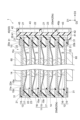
- FIG. 4 is a schematic cross-sectional view of a portion of the power storage module shown in FIG. 3.
- FIG. 5 is a schematic diagram showing a part of the power storage module shown in FIG. 1.
- FIG. 6 is a schematic diagram showing a part of the power storage module shown in FIG. 1.
- FIG. 7 is a schematic cross-sectional view showing a modification of the spacer shown in FIGS. 2 and 3.
- FIG. FIG. 8 is a schematic cross-sectional view of a power storage module according to a modification.
- FIG. 9 is a schematic cross-sectional view of a power storage module according to another modification.
- FIG. 1 is a schematic plan view of the electricity storage module according to the present embodiment.
- FIG. 2 is a schematic cross-sectional view taken along line II-II in FIG.
- FIG. 3 is a schematic cross-sectional view taken along line III--III in FIG.
- FIG. 4 is a schematic cross-sectional view of a portion of the power storage module shown in FIG. 3.
- the power storage module 1 shown in FIGS. 1 to 4 is, for example, a power storage module used in batteries of various vehicles such as forklifts, hybrid vehicles, and electric vehicles.
- the power storage module 1 is, for example, a secondary battery such as a nickel metal hydride secondary battery or a lithium ion secondary battery.
- the power storage module 1 may be an electric double layer capacitor or an all-solid-state battery.
- a case is shown in which the power storage module 1 is a lithium ion secondary battery.
- the power storage module 1 includes an electrode laminate 10, a first resin part 20, and a sealing body 50. Note that in FIG. 1, illustration of the sealing body 50 is omitted.
- the electrode stack 10 includes a plurality of electrodes stacked along the first direction D1.
- the first direction D1 is the stacking direction of the electrodes, and is the height direction of the power storage module 1.
- the plurality of electrodes include a plurality of bipolar electrodes 11, a positive terminal electrode 12, and a negative terminal electrode 13.
- a separator 14 is interposed between adjacent electrodes.
- the bipolar electrode 11 has a current collector 15 , a positive electrode active material layer 16 , and a negative electrode active material layer 17 .
- the current collector 15 has a rectangular sheet shape, for example.
- the positive electrode active material layer 16 is provided on one side 15a of the current collector 15.
- the negative electrode active material layer 17 is provided on the other surface 15b of the current collector 15.
- the plurality of bipolar electrodes 11 are stacked such that the positive electrode active material layer 16 of one bipolar electrode 11 and the negative electrode active material layer 17 of another bipolar electrode 11 face each other.
- one surface 15a of the current collector 15 is a surface facing one side in the first direction D1
- the other surface 15b of the current collector 15 is a surface facing the other side in the first direction D1.
- the positive electrode active material layer 16 and the negative electrode active material layer 17 have a rectangular shape when viewed from the first direction D1.
- the negative electrode active material layer 17 is one size larger than the positive electrode active material layer 16 when viewed from the first direction D1. That is, in a plan view seen from the first direction D1, the entire formation region of the positive electrode active material layer 16 is located within the formation region of the negative electrode active material layer 17.
- the positive terminal electrode 12 includes a current collector 15 and a positive active material layer 16 provided on one side 15a of the current collector 15.
- the positive terminal electrode 12 does not have the positive active material layer 16 and the negative active material layer 17 on the other surface 15b of the current collector 15. That is, no active material layer is provided on the other surface 15b of the current collector 15 of the positive terminal electrode 12.
- the positive terminal electrode 12 is stacked on the bipolar electrode 11 at the other end of the electrode stack 10 in the first direction D1.
- the positive terminal electrode 12 is stacked on the bipolar electrode 11 such that the positive active material layer 16 faces the negative active material layer 17 of the bipolar electrode 11 .
- the negative terminal electrode 13 includes a current collector 15 and a negative active material layer 17 provided on the other surface 15b of the current collector 15.
- the negative terminal electrode 13 does not have the positive active material layer 16 and the negative active material layer 17 on one side 15a of the current collector 15. That is, no active material layer is provided on one side 15a of the current collector 15 of the negative terminal electrode 13.
- the negative terminal electrode 13 is stacked on the bipolar electrode 11 at one end of the electrode stack 10 in the first direction D1.
- the negative terminal electrode 13 is stacked on the bipolar electrode 11 such that its negative active material layer 17 faces the positive active material layer 16 of the bipolar electrode 11 .
- the separator 14 is arranged so as to be sandwiched between adjacent bipolar electrodes 11, between the positive terminal electrode 12 and the bipolar electrode 11, and between the negative terminal electrode 13 and the bipolar electrode 11. Separator 14 is interposed between positive electrode active material layer 16 and negative electrode active material layer 17. By separating the positive electrode active material layer 16 and the negative electrode active material layer 17, the separator 14 prevents short circuits due to contact between adjacent electrodes while allowing charge carriers such as lithium ions to pass through.
- the current collector 15 is a chemically inert electrical conductor that allows current to continue flowing through the positive electrode active material layer 16 and the negative electrode active material layer 17 during discharging or charging of the lithium ion secondary battery.
- the material of the current collector 15 is, for example, a metal material, a conductive resin material, or a conductive inorganic material.
- the conductive resin material include resins in which a conductive filler is added to a conductive polymer material or a non-conductive polymer material as necessary.
- Current collector 15 may include multiple layers. In this case, each layer of the current collector 15 may contain the above metal material or conductive resin material.
- a coating layer may be formed on the surface of the current collector 15.
- the coating layer may be formed by a known method such as plating or spray coating.
- the current collector 15 may have, for example, a plate shape, a foil shape (eg, metal foil), a film shape, or a mesh shape.
- the metal foil include aluminum foil, copper foil, nickel foil, titanium foil, and stainless steel foil.
- the stainless steel foil include SUS 304, SUS 316, and SUS 301 defined in JIS G 4305:2015. By using stainless steel foil as the current collector 15, the mechanical strength of the current collector 15 can be ensured.
- the current collector 15 may be an alloy foil or clad foil of the above metal. When the current collector 15 has a foil shape, the thickness of the current collector 15 may be, for example, 1 ⁇ m to 100 ⁇ m.
- the positive electrode active material layer 16 includes a positive electrode active material that can insert and release charge carriers such as lithium ions.
- the positive electrode active material include lithium composite metal oxides having a layered rock salt structure, metal oxides having a spinel structure, and polyanionic compounds.
- the positive electrode active material may be any material that can be used in lithium ion secondary batteries.
- the positive electrode active material layer 16 may include a plurality of positive electrode active materials.
- the positive electrode active material layer 16 contains olivine-type lithium iron phosphate (LiFePO 4 ) as a composite oxide.
- the negative electrode active material layer 17 includes a negative electrode active material that can insert and release charge carriers such as lithium ions.
- the negative electrode active material may be a single substance, an alloy, or a compound.
- Examples of the negative electrode active material include Li, carbon, and metal compounds.
- the negative electrode active material may be an element that can be alloyed with lithium, a compound thereof, or the like.
- Examples of carbon include natural graphite, artificial graphite, hard carbon (hardly graphitizable carbon), and soft carbon (easily graphitizable carbon).
- Examples of the artificial graphite include highly oriented graphite, mesocarbon microbeads, and the like.
- Examples of elements that can be alloyed with lithium include silicon, tin, and the like.
- the negative electrode active material layer 17 contains graphite as a carbon-based material.
- Each of the positive electrode active material layer 16 and the negative electrode active material layer 17 may contain a conductive agent, a binder, an electrolyte ( (a polymer matrix, an ion-conducting polymer, an electrolytic solution, etc.), an electrolyte supporting salt (lithium salt) for enhancing ion conductivity, and the like.
- the conductive additive is added to improve the conductivity of each electrode (bipolar electrode 11, positive terminal electrode 12, negative terminal electrode 13).
- the conductive aid include acetylene black, carbon black, and graphite.
- fluorine-containing resins such as polyvinylidene fluoride, polytetrafluoroethylene, and fluororubber, thermoplastic resins such as polypropylene and polyethylene, imide resins such as polyimide and polyamideimide, alkoxysilyl group-containing resins, and acrylic acid can be used.
- acrylic resins such as methacrylic acid, styrene-butadiene rubber (SBR), carboxymethyl cellulose, alginates such as sodium alginate and ammonium alginate, water-soluble cellulose ester crosslinked products, starch-acrylic acid graft polymers, and the like.
- SBR styrene-butadiene rubber
- alginates such as sodium alginate and ammonium alginate
- water-soluble cellulose ester crosslinked products starch-acrylic acid graft polymers, and the like.
- solvent for example, water, N-methyl-2-pyrrolidone (NMP), etc. are used.
- the separator 14 may be, for example, a porous sheet or nonwoven fabric containing a polymer that absorbs and retains electrolyte.
- Examples of the material for the separator 14 include polypropylene, polyethylene, polyolefin, polyester, and the like.
- Separator 14 may have a single layer structure or a multilayer structure.
- the multilayer structure may have, for example, a ceramic layer as an adhesive layer or a heat-resistant layer.
- the separator 14 may be impregnated with an electrolyte.
- the separator 14 may be made of an electrolyte such as a polymer electrolyte or an inorganic electrolyte.
- the electrolyte impregnated into the separator 14 is, for example, a liquid electrolyte (electrolyte) containing a non-aqueous solvent and an electrolyte salt dissolved in the non-aqueous solvent, or a polymer gel electrolyte containing an electrolyte held in a polymer matrix. etc.
- a liquid electrolyte electrolyte (electrolyte) containing a non-aqueous solvent and an electrolyte salt dissolved in the non-aqueous solvent
- a polymer gel electrolyte containing an electrolyte held in a polymer matrix.
- examples of the electrolyte salt include LiClO 4 , LiAsF 6 , LiPF 6 , LiBF 4 , LiCF 3 SO 3 , LiN(FSO 2 ) 2 , LiN(CF 3 SO 2 ) 2 and the like. Any known lithium salt may be used.
- nonaqueous solvent known solvents such as cyclic carbonates, cyclic esters, chain carbonates, chain esters, and ethers may be used. Note that two or more of these known solvent materials may be used in combination.
- the first resin part 20 is formed in a frame shape at the peripheral edge of the electrode stack 10 so as to surround the electrode stack 10.
- the first resin portion 20 may be joined to each of the one side 15a and the other side 15b of the current collector 15 at the peripheral edge 15c of each current collector 15.
- the first resin part 20 is for forming an internal space S between adjacent current collectors 15 in the first direction D1 and for sealing each of the internal spaces S.
- Each internal space S accommodates an electrolytic solution (not shown). That is, the first resin part 20 defines an internal space S that accommodates the electrolytic solution together with the current collector 15 adjacent in the first direction D1.
- the first resin portion 20 prevents the electrolyte from permeating to the outside.
- the first resin portion 20 suppresses moisture and the like from entering the internal space S from the outside of the electrode stack 10.
- the first resin portion 20 has, for example, a diffusion coefficient and a permeability coefficient adjusted to suppress the air from flowing into the internal space S from the outside of the electrode stack 10, so that the first resin portion 20 has a permeation coefficient that makes it difficult for the air to pass through the resin. You can leave it there.
- the edge of the separator 14 is joined to the first resin part 20.
- the first resin portion 20 includes an insulating material. Examples of the material for the first resin part 20 include various resin materials such as polypropylene, polyethylene, polystyrene, ABS resin, acid-modified polypropylene, acid-modified polyethylene, and acrylonitrile styrene resin.
- the first resin portion 20 includes a plurality of sealants 21 , a plurality of spacers 22 , and a welded end portion 23 .
- the sealing material 21 is provided on each of the current collectors 15. Therefore, the sealing materials 21 are stacked on each other along the first direction D1.
- the sealing material 21 has a frame shape when viewed from the first direction D1, and is provided on the peripheral edge portion 15c of the current collector 15.
- the sealing material 21 is provided from one surface 15a of the current collector 15 to the other surface 15b via the end surface, and covers the peripheral edge 15c.
- the sealing material 21 is welded to both one side 15a and the other side 15b of the current collector 15.
- one sealing material 21 has a frame shape when viewed from the first direction, and is composed of a pair of base materials provided so as to sandwich the peripheral edge 15c of the current collector 15.
- One of the pair of base materials is disposed at the peripheral edge 15c of the current collector 15 so as to extend from one surface 15a of the current collector 15 beyond the end surface, and is welded to the one surface 15a.
- the other of the pair of base materials is arranged at the peripheral edge 15c of the current collector 15 so as to extend from the other surface 15b of the current collector 15 beyond the end surface, and is welded to the other surface 15b. Then, the pair of base materials are overlapped with each other in a portion beyond the end surface of the current collector 15, and are partially welded to form a welded end portion 23 as described later.
- the spacer 22 is arranged to be interposed between the sealing materials 21 adjacent to each other in the first direction D1. Thereby, the spacer 22 maintains a space between adjacent sealing materials 21, that is, between adjacent current collectors 15.
- the spacer 22 has a frame shape when viewed from the first direction D1, and is arranged on the peripheral edge 15c of the current collector 15. The spacer 22 is in contact with a pair of sealing materials 21 adjacent to each other in the first direction D1.
- the welded end portion 23 is formed by welding and integrating the ends (outer peripheries) of the plurality of sealing materials 21 and the plurality of spacers 22 on the side opposite to the internal space S.
- the sealing material 21 and the spacer 22 are not welded together except for the welded end portion 23, and are only in contact with each other.
- the welded end portion 23 has a frame shape surrounding the electrode stack 10 when viewed from the first direction D1.
- the side surface of the welded end portion 23 opposite to the internal space S extends along the first direction D1, and constitutes the outer surface 20s of the first resin portion 20.
- the first resin portion 20 includes an outer surface 20s opposite to the inner space S.
- Communication holes 27 are formed in the first resin portion 20 to communicate with each of the plurality of internal spaces S (see FIGS. 1 and 4).
- the communication hole 27 is formed to penetrate the spacer 22 and the welded end portion 23.
- the communication hole 27 has one opening in the internal space S and the other opening 27h in the outer surface 20s of the first resin part 20.
- a cell C including one internal space S is formed between a pair of adjacent current collectors 15.
- one communication hole 27 is formed for one cell C.
- the outer surface 20s of the first resin part 20 includes one first outer surface 20sA in which the opening 27h of the communication hole 27 is formed, and the other three second outer surfaces 20sB, 20sC, and 20sD.
- the second outer surface 20sB is a surface opposite to the first outer surface 20sA
- the second outer surface 20sC and the second outer surface 20sD are surfaces connecting the first outer surface 20sA and the second outer surface 20sB.
- both ends of the first resin part 20 in the first direction D1 are each made of a sealing material 21. Therefore, the first end surface 20a and the second end surface 20b of the first resin part 20 in the first direction D1 are the outer surfaces of the pair of sealants 21 disposed at both ends of the first resin part 20 in the first direction D1. has been done.
- the outer surface of the first resin part 20 has a first end surface 20a in the first direction D1, a second end surface 20b opposite to the first end surface 20a in the first direction D1, and a first end surface 20a and a second end surface 20b on the opposite side of the first end surface 20a in the first direction D1. It includes four outer side surfaces 20s extending along the first direction D1 so as to connect the two end surfaces 20b.
- the four outer surfaces 20s are the outer surfaces of the welded end portion 23. Openings 27h of a plurality of communication holes 27 are formed in the first outer surface 20sA, which is one of the four outer surfaces 20s.
- the opening 27h of the communication hole 27 is not provided in the three second outer surfaces 20sB, 20sC, and 20sD that are different from the first outer surface 20sA among the four outer surfaces 20s.
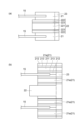
- FIGS. 5 and 6 are schematic diagrams showing a part of the electricity storage module shown in FIG. 1.
- 5(a) is an enlarged plan view of region R1 in FIG. 1
- FIG. 5(b) is an enlarged sectional view taken along the line Vb--Vb in FIG. 1.
- 6(a) is an enlarged plan view of region R2 in FIG. 1
- FIG. 6(b) is an enlarged sectional view taken along line VIb-VIb in FIG.
- the sealing body 50 shown in FIGS. 2, 3, 5, and 6 has a rectangular frame shape when viewed from the first direction D1, and has a first end surface 20a, a second end surface 20b, and an outer surface 20s of the first resin part 20. It is provided.
- the sealing body 50 is joined (welded) to each of the first end surface 20a and the second end surface 20b and the outer surface 20s.
- the sealing body 50 includes a laminate sheet 30 and a second resin part (injection resin part) 40.
- the sealing body 50 does not have to be frame-shaped.
- the laminate sheet 30 has a rectangular frame shape when viewed from the first direction D1, and includes second outer surfaces 20sB, 20sC, and 20sD of the outer surface 20s of the first resin part 20, a first end surface 20a, and a second end surface. 20b.
- the laminate sheet 30 includes a metal layer 30a, a first insulating layer 30b laminated on the metal layer 30a, and a second insulating layer 30c laminated on the metal layer 30a on the opposite side of the first insulating layer 30b.
- the laminate sheet 30 is welded to the first resin portion 20 at the first insulating layer 30b.
- the first insulating layer 30b is made of an insulating resin.
- the material of the first insulating layer 30b is, for example, polypropylene, polyethylene, polyamide, or the like.
- the material of the first insulating layer 30b may be selected from the same materials as the first resin part 20 from the viewpoint of adhesiveness with the first resin part 20.
- the metal layer 30a is made of a material with low moisture permeability (low moisture permeability coefficient), such as aluminum foil or stainless steel foil, for example.
- the second insulating layer 30c is made of, for example, a resin having insulating properties.
- the material of the second insulating layer 30c is, for example, polypropylene, nylon, or the like.
- the laminate sheet 30 is an aluminum laminate sheet, and polypropylene may be selected as the first insulating layer 30b, aluminum may be selected as the metal layer 30a, and polyethylene terephthalate may be selected as the second insulating layer 30c.
- the laminate sheet 30 is welded to at least the first end surface 20a and the second end surface 20b, and here, it is also welded to the second outer surfaces 20sB, 20sC, and 20sD.
- the laminate sheet 30 includes a pair of end surfaces 31 disposed on each of the first end surface 20a and the second end surface 20b, and a side surface section 32 disposed on the second outer surfaces 20sB, 20sC, and 20sD. .
- the laminate sheet 30 covers at least a portion of the first end surface 20a and the second end surface 20b of the first resin part 20 in the first direction D1, and substantially the entire second outer surfaces 20sB, 20sC, and 20sD. Therefore, in the first direction D1 and the second direction D2 and the third direction D3 intersecting the first direction D1, moisture permeation and gas permeation are suppressed (and pressure resistance is In other words, it contributes to improving the sealing performance.
- the second resin portion 40 has a rectangular frame shape when viewed from a third direction D3 intersecting the first direction D1, and has a first outer surface 20sA of the outer surfaces 20s of the first resin portion 20 and a first end surface. 20a and the second end surface 20b.
- the second resin part 40 is welded to at least the first end surface 20a and the second end surface 20b, and here, it is also welded to the first outer surface 20sA. More specifically, the second resin part 40 may be provided on the first end surface 20a, the second end surface 20b, and the first outer surface 20sA by injection molding.
- the second resin part 40 includes a reinforcing part 41 and a frame part 42.
- a rectangular frame portion 42 is formed on the first outer surface 20sA where the opening 27h of the communication hole 27 is formed so as to surround the opening 27h when viewed from the third direction D3.
- the frame portion 42 is provided to protrude from the base portion 40p on the first outer surface 20sA of the second resin portion 40 in the third direction D3.
- the base portion 40p is a plate-shaped portion welded to the first outer surface 20sA. Thereby, on the first outer surface 20sA, the welded end portion 23 and the base portion 40p are stacked along the third direction D3.
- the reinforcing portion 41 is provided on each of the first end surface 20a and the second end surface 20b. More specifically, the reinforcing portion 41 is provided from the sealing material 21 to the welded end portion 23. By being provided on the first end surface 20a and the second end surface 20b, the reinforcing portion 41 increases the thickness of the resin portion in the first direction D1, that is, from the internal space S in the first direction D1 to the outside of the power storage module 1. , and contributes to suppressing moisture permeation and suppressing gas permeation (and improving pressure resistance), that is, increasing sealing performance, along the first direction D1 between the internal space S and the outside. There is.
- a base portion 40p which is a resin portion corresponding to the reinforcing portion 41, is provided on the first outer surface 20sA of the first resin portion 20.
- the thickness of the resin part (sealing material 21 or spacer 22 and welded end part 23) excluding the second resin part 40 in the third direction D3, that is, the internal space in the third direction D3 excluding the second resin part 40 Since the distance from S to the outside of the power storage module 1 is larger than in the first direction D1, moisture permeation and gas permeation are less likely to occur than in the first direction D1.
- the base portion 40p is provided and a sealing film 45, which will be described later, is provided on the frame portion 42, moisture permeation and gas permeation in the third direction D3 are further suppressed.
- the frame portion 42 has a rectangular frame shape surrounding each opening 27h of the plurality of communication holes 27 (through the base portion 40p) when viewed from the third direction D3 intersecting the first outer surface 20sA. ) is provided on the first outer surface 20sA.
- a through hole is provided in the base portion 40p at a position corresponding to the communication hole 27, so that the opening 27h of the communication hole 27 communicates with a region 43 surrounded by the frame portion 42.
- the frame portion 42 is used, for example, when pouring electrolyte into each of the internal spaces S.
- the nozzle of the electrolyte injector when injecting the electrolyte, the nozzle of the electrolyte injector is brought into close contact with the top surface of the frame 42, and the electrolyte is injected into each region 43 from the nozzle. Introduce. Thereby, it becomes possible to inject the electrolyte into the internal space S from the communication hole 27 connected to each region 43 via the opening 27h.
- a sealing film 45 is attached to the frame portion 42 .
- the sealing film 45 may have the same layer structure and material as the laminate sheet 30, for example. Thereby, the communication hole 27 and the internal space S are sealed.
- the second resin part 40 can have the functions of injecting electrolyte and sealing the internal space S in addition to the function of the sealing body 50. That is, the second resin part 40 also serves as a liquid injection frame here.
- the first resin portion 20 has a rectangular ring shape when viewed from the first direction D1, and is composed of portions corresponding to four sides of the rectangle.
- One of the portions corresponding to the four sides is the first portion 20A that includes a region of the first outer surface 20sA in which the opening 27h of the communication hole 27 is formed.
- the parts corresponding to the other three sides are a second part 20B including the second outer surface 20sB, a second part 20C including the second outer surface 20sC, and a second part 20C including the second outer surface 20sC.
- the first outer surface the one on which the opening 27h of the communication hole 27 is formed
- the second outer surface the other part
- first part the part including the area around the opening 27h of the communication hole 27 on the "first outer surface” when viewed from the first direction D1
- second part the part including the area around the opening 27h of the communication hole 27 on the "first outer surface” when viewed from the first direction D1
- first part the part including the area around the opening 27h of the communication hole 27 on the "first outer surface” when viewed from the first direction D1
- the other part is referred to as the “second part”. It is called "part”.
- the spacer 22 has a rectangular ring shape when viewed from the first direction D1, and is composed of four first side portions 22A to 22D corresponding to the four sides of the rectangle.
- the first side portion 22A is a portion included in the first portion 20A of the first resin portion 20
- the first side portion 22B is a portion included in the second portion 20B of the first resin portion 20.
- the first side portion 22C is a portion included in the second portion 20C of the first resin portion
- the first side portion 22D is a portion included in the second portion 20D of the first resin portion 20.
- FIG. 5 a part of the first resin portion 20 of the power storage module 1, including the second portion 20D, is illustrated.
- the positional relationship among the current collector 15, the sealant 21, the spacer 22 (ie, the first side portion 22D), and the laminate sheet 30 will be described.
- the inner edge 21e of the sealing material 21 is located inside the outer edge 15e of the current collector 15 (that is, on the inner space S side).
- the inner edge 30e of the (end surface portion 31) of the laminate sheet 30 is inside the outer edge 15e of the current collector 15, and substantially coincides with the inner edge 21e of the sealing material 21. .
- the inner edge 22e of the spacer 22 (first side portion 22D) is located inside the inner edge 21e of the sealing material 21.
- the spacer 22 includes a protrusion 22p that protrudes inward from the inner edge 21e of the sealing material 21 when viewed from the first direction D1. That is, when viewed from the first direction D1, the entire area where the sealant 21 is provided becomes an area (grip area) where the sealant 21 and the spacer 22 overlap.
- the entire sealing material 21 (the entire surface of the first end surface 20a and the second end surface 20b) can be pressed in the first direction D1 by the sealer SD, The welding allowance for the laminate sheet 30 is ensured. Note that the end of the separator 14 is overlapped with the protrusion 20p and welded to the spacer 22.
- portions of the first resin portion 20 in the electricity storage module 1 corresponding to the second portions 20B and 20C have a similar positional relationship.
- FIG. 6 a part of the first resin portion 20 of the power storage module 1, including the first portion 20A, is illustrated.
- the same description will be made regarding the positional relationship among the current collector 15, the sealing material 21, the spacer 22 (ie, the first side portion 22A), and the second resin portion 40.
- the inner edge 21e of the sealing material 21 is located inside the outer edge 15e of the current collector 15 (that is, on the inner space S side) when viewed from the first direction D1.
- the inner edge 40e of the second resin portion 40 is located inside the outer edge 15e of the current collector 15 and outside the inner edge 21e of the sealing material 21. are doing.
- the inner edge 22e of the spacer 22 (first side portion 22A) is located inside the inner edge 21e of the sealing material 21.
- the spacer 22 includes a protrusion 22p that protrudes inward from the inner edge 21e of the sealing material 21 when viewed from the first direction D1.
- the end of the separator 14 is overlapped with the protrusion 20p and welded to the spacer 22. That is, when viewed from the first direction D1, the entire area where the sealant 21 is provided is an area where the sealant 21 and the spacer 22 overlap.
- the edge of the mold MD is placed directly above (directly below) the inner edge 21e of the sealing material 21 and It becomes possible to grip along D1, and a formation area for the second resin part 40 (reinforcement part 41) is secured.
- the end of the separator 14 is overlapped with the protrusion 20p and welded to the spacer 22.
- the second resin part 40 When forming the second resin part 40 by injection molding, first, a mold MD is attached to the laminate including the electrode laminate 10 and the first resin part 20. Then, the second resin portion 40 is molded by injecting resin into the molding space of the mold MD attached to the laminate.
- the area (gripping area) where the plurality of current collectors 15, the plurality of sealants 21, and the plurality of spacers 22 overlap when viewed from the first direction D1 is attached to the mold. It can be held (grasped) by the MD. In this case, in the grip region, no space is formed in the stacking direction in which the spacer 22 does not exist. Therefore, stable clamping by the mold MD is possible (the second resin part 40 can be stably formed).
- the second resin portion 40 is formed by injection molding.
- the end surface portion 31 may be provided beforehand, or the end surface portion 31 may be provided after the second resin portion 40 is formed by injection molding.
- the inner edges 22e of all the first side portions 22A to 22D of the spacer 22 are located inside the inner edge 21e of the sealing material 21, and include the protruding portions 22p.
- the second resin portion 40 is provided only in the first portion 20A of the first portion 20A and the second portions 20B to 20D of the first resin portion 20.
- a laminate sheet 30 is provided on the second portions 20B to 20D of the first portion 20A and the second portions 20B to 20D of the first resin portion 20.
- the end surface portion 31 of the laminate sheet 30 is provided on the first end surface 20a and the second end surface 20b of the first portion 20A as well.
- the end surface portion 31 is disposed and joined to at least the portion of the first end surface 20a and the second end surface 20b exposed from the reinforcing portion 41 of the second resin portion 40.
- the end surface portion 31 is provided on the first end surface 20a and/or the second end surface 20b prior to injection molding of the second resin portion 40, so that at least a portion of the end surface portion 31 is formed on the first end surface 20a. And/or it may be further arranged between the second end surface 20b and the reinforcing portion 41.
- a conductive member 60 functioning as a terminal for taking out is arranged and electrically connected.
- the conductive member 60 can be used to electrically connect the plurality of power storage modules 1. Further, the conductive member 60 can also be used as a restraining member to apply a restraining load to the electrode stack 10.
- a cooling channel may be formed in the conductive member 60. The electrode stack 10 can be cooled by flowing a cooling medium through the cooling channel formed in the conductive member 60.
- a spacer may be interposed between adjacent seal portions attached to each current collector and facing each other in the stacking direction.
- the inner edge of the spacer is located outside the inner edge of the seal portion (that is, the spacer portion is recessed).
- a sealing body may be provided on the outside of the seal portion for various purposes such as suppressing moisture permeation between the internal space and the outside, suppressing gas permeation, or improving pressure resistance.
- a sheet-shaped sealing body is placed on the sealing part, and pressure is applied in the stacking direction while applying heat to the sealing body with a sealer to weld it to the sealing part, or the sealing body is welded to the sealing part along the stacking direction. It is conceivable to improve the sealability by arranging a mold so as to grip the part and forming a sealed body by injection molding using the mold.
- the pressing force/gripping force must be applied to the area where the seal part is provided, where the spacer is not interposed between the seal parts (the area inside the inner edge of the spacer). This may make it difficult to provide a sealing body. In such a situation, it is desirable to make the area where the sealing body is provided as wide as possible with respect to the entire area where the sealing material is provided, and to provide a larger and more stable sealing body.
- the first resin A sealing body 50 is bonded to a first end surface 20a and a second end surface 20b of the first resin section 20 in the first direction D1.
- a spacer 22 is interposed between a sealing material 21 provided on the peripheral edge 15c of the current collector 15 of the electrode.
- an internal space S is formed by the sealing material 21 and the spacer 22 between the current collectors 15 adjacent to each other along the first direction D1.
- a plurality of communication holes 27 are formed that communicate the first outer surface 20sA of the four outer surfaces 20s of the first resin part 20 with the internal space S. This communication hole 27 can be used, for example, as a liquid inlet for injecting electrolyte into the internal space S.
- the spacer 22 In the first portion 20A of the first outer surface 20sA of the first resin part 20, which includes the region where the opening 27h of the communication hole 27 is formed, at least a portion of the inner edge 22e of the spacer 22 is (all of them here) are located inside the inner edge 21e of the sealing material 21. Therefore, when viewed from the first direction D1, the spacer 22 is interposed beyond the inner edge 21e of the sealing material 21 in at least a portion thereof. Therefore, it becomes possible to arrange the mold MD for injection molding, a heat sealer, etc. as described above using the part as a gripping area, and apply pressing force and gripping force to provide the sealing body 50. Therefore, it becomes possible to stably provide the sealing body 50 for improving sealing performance.
- the sealing body 50 includes the second resin portion 40 welded to the first end surface 20a and the second end surface 20b in the first portion 20A. Therefore, by arranging the mold MD for injection molding as described above with the portion where the inner edge 22e of the spacer 22 is located inside the inner edge 21e of the sealing material 21 as the gripping area, the injection resin portion It becomes possible to stably provide the second resin part 40.
- the sealing body 50 has a laminate sheet 30 including a metal layer 30a and a first insulating layer 30b laminated on the metal layer 30a.
- 30b is welded to the first end surface 20a and second end surface 20b of the first resin part 20. Therefore, the laminate sheet 30 can suitably suppress moisture permeation and gas permeation in the internal space S and improve the strength.
- the electrode stack 10 includes a separator 14 interposed between each of the plurality of electrodes adjacent to each other in the first direction D1, and the spacer 22 is a part of the sealing material 21 when viewed from the first direction D1. It includes a protrusion 22p that protrudes inward from the inner edge 21e. The end of the separator 14 is overlapped and welded to the protrusion 22p. Therefore, if the melting point of the spacer 22 is made relatively high, as long as the melting point of the spacer 22 is not exceeded, short circuits between the current collectors 15 will not occur, and heat resistance will be improved.
- the four outer surfaces include three second outer surfaces that are different from the first outer surface, and include each of the three second outer surfaces of the first resin part.
- the inner edge of the spacer may be located inside the inner edge of the sealing material when viewed from the first direction.
- the inner edge of the spacer is positioned inside the inner edge of the sealing material.
- the sealing body may include an injection resin portion welded to the first end surface and the second end surface in the first portion.
- the first portion including the portion where the inner edge of the spacer is located inside the inner edge of the sealing material becomes the gripping area.
- the sealing body includes a laminate sheet including a metal layer and an insulating layer laminated on the metal layer, and the laminate sheet may be welded to the first end surface and the second end surface.
- the laminate sheet including the metal layer can suitably suppress moisture permeation and gas permeation in the internal space and improve strength.
- the electrode stack includes a separator interposed between each of the plurality of electrodes adjacent in the first direction, and the end of the separator is connected to the sealing material and the spacer in the first direction. It may be placed in between. In this case, if the melting point of the spacer is made relatively high, short circuits between current collectors will not occur unless the melting point of the spacer is exceeded, and heat resistance will be improved.
- the power storage module according to the present disclosure may be an arbitrary modification of the power storage module 1 described above.
- the spacer 22 may have a multilayer structure, as shown in FIG. 7(a).
- the spacer 22 includes an intermediate layer 221, a pair of outermost layers 222 laminated on both sides of the intermediate layer 221, and a pair of adhesive layers 223 interposed between each of the intermediate layer 221 and the outermost layer 222. and can include.
- the intermediate layer 221 is made of a material with excellent heat resistance and gas permeability (for example, PP)
- the outermost layer 222 is made of a material that is highly compatible with the material of the sealing material 21 (for example, low-density PE) (for example, (a mixed material of PE and PP, etc.).
- the adhesive layer 223 is a layer that adheres the intermediate layer 221 and the outermost layer 222, and is provided as necessary (that is, it may be omitted).
- each of the pair of base materials 21a constituting one sealing material 21 has a multilayer structure.
- each of the base materials 21a includes an intermediate layer 211, a pair of outermost layers 212 laminated on both sides of the intermediate layer 211, and a pair of outermost layers 212 interposed between each of the intermediate layer 211 and the outermost layer 212.
- An adhesive layer 213 is included.
- the intermediate layer 211, the outermost layer 212, and the adhesive layer 213 may be made of the same materials as the intermediate layer 221, the outermost layer 222, and the adhesive layer 223 shown in FIG. 7(a).
- hatching of each part is omitted.
- an insulator (not shown) is provided to cover the end of the laminate sheet 30.
- an example of the insulator may be an insulating film that is pasted from one side 15a and/or the other side 15b of the current collector 15 to the end of the laminate sheet 30. In this case, insulation of the laminate sheet 30 is achieved. As a result, a short circuit between the positive terminal electrode 12 and the negative terminal electrode 13 of the electrode stack 10 via the metal layer 30a of the laminate sheet 30 is suppressed.
- the entire inner edge 22e of the spacer 22 is located inside the inner edge 21e of the sealing material 21 when viewed from the first direction D1.
- at least a portion (for example, at least one side portion) of the inner edge 22e of the spacer 22 only needs to be located inside the inner edge 21e of the sealing material 21.
- the inner edge 22e of the spacer 22 is covered with the sealing material when viewed from the first direction D1. It may be located outside the inner edge 21e of 21. That is, in the electricity storage module 1, at least in the first portion 20A of the first resin portion 20, which includes the region where the opening 27h of the communication hole 27 of the first outer surface 20sA is formed, the inner edge of the spacer 22 as seen from the first direction D1. At least a portion of 22e may be located inside the inner edge 21e of the sealing material 21.
- the inner edge 22e of the spacer 22 is similarly located outside the inner edge 21e of the sealing material 21. You may do so.
- the spacer 22 is By locating the inner edge 22e outside the inner edge 21e of the sealing material 21, it is possible to secure a large volume of the internal space S.
- the second side portions other than the first side portion 22A among the plurality of side portions of the spacer 22 may be located outside the inner edge 21e of the sealing material 21.
- the side portion whose inner edge is located inside the inner edge 21e of the sealing material 21 is referred to as a “first side portion”, and the other portions are referred to as a “second side portion”. ”.
- the end surface portion 31 of the laminate sheet 30 is attached to the first resin portion 20 provided on the peripheral edge portion 15c of the current collector 15 in advance. It can be pressed and welded with a sealer SD.
- the end surface portion 31 is provided before forming the second resin portion 40 by injection molding, but the end surface portion 31 may be provided after forming the second resin portion 40 by injection molding.
- the separator 14 may extend between the sealing material 21 and the spacer 22.
- the peripheral edge of the separator 14 is sandwiched between the sealing material 21 and the spacer 22 and welded to the first resin part 20.
- a portion of the first resin portion 20 corresponding to the first outer surface 20sA includes a first portion including the region where the opening 27h of the communication hole 27 is formed in the first outer surface 20sA, and a second portion other than the region.
- the inner edge 22e of the spacer 22 may be located outside the inner edge 21e of the sealing material 21. In this case, since the inner edge 22e of the spacer 22 is located inside the inner edge 21e of the sealing material 21 only within the minimum necessary range, it is possible to secure a large internal space S.
- FIG. 9 is a schematic cross-sectional view of a power storage module according to another modification.
- the separator 14 extends between the sealing material 21 and the spacer 22, similar to the example shown in FIG. Thereby, the end portion of the separator 14 is arranged between the sealing material 21 and the spacer 22 in the first direction D1. Also in this example, the peripheral edge of the separator 14 is sandwiched between the sealing material 21 and the spacer 22 and welded to the first resin part 20.
- a portion of the first resin portion 20 corresponding to the first outer surface 20sA corresponds to a region of the first outer surface 20sA in which the opening 27h of the communication hole 27 is formed.
- the inner edge 22e of the spacer 22 is in contact with the sealing material 21. It may be located inside the inner edge 21e of. In this case, it is possible to provide the sealing body 50 by applying pressing force and gripping force.
- the sealing body 50 has a rectangular annular shape when viewed from the first direction D1, but the sealing body 50 does not have to be annular when viewed from the first direction D1.
- the sealing body 50 may be provided on at least one of the portions (first portion 20A and second portions 20B to 20D) corresponding to the four sides of the first resin portion 20.
- the sealing body 50 may be provided only in a part of the first resin part 20 corresponding to one side.
- the laminate sheet 30 including the metal layer 30a is illustrated.
- the laminate sheet 30 may include a resin layer instead of the metal layer 30a.
- the material of the resin layer may be polypropylene, polyethylene, polyamide, polyimide, polyvinyl alcohol, ethylene vinyl alcohol copolymer, or the like.
- SYMBOLS 1 Electricity storage module, 10... Electrode laminated body, 15... Current collector, 15e... Outer edge, 20... First resin part, 20A... First part, 20B, 20C, 20D... Second part, 20a... First end surface, 20b... Second end surface, 20s... Outer surface, 20sA... First outer surface, 20sB, 20sC, 20sD... Second outer surface, 21... Seal material, 21e, 22e, 30e, 40e... Inner edge, 22... Spacer, 22p...
Landscapes
- Chemical & Material Sciences (AREA)
- Chemical Kinetics & Catalysis (AREA)
- Electrochemistry (AREA)
- General Chemical & Material Sciences (AREA)
- Engineering & Computer Science (AREA)
- Power Engineering (AREA)
- Microelectronics & Electronic Packaging (AREA)
- Manufacturing & Machinery (AREA)
- Inorganic Chemistry (AREA)
- Sealing Battery Cases Or Jackets (AREA)
Priority Applications (5)
| Application Number | Priority Date | Filing Date | Title |
|---|---|---|---|
| JP2024540365A JP7772232B2 (ja) | 2022-08-12 | 2023-07-26 | 蓄電モジュール |
| EP23852377.3A EP4553936A4 (en) | 2022-08-12 | 2023-07-26 | ELECTRICAL ENERGY STORAGE MODULE |
| CN202380058933.3A CN119678279A (zh) | 2022-08-12 | 2023-07-26 | 蓄电模块 |
| US19/101,076 US20260074334A1 (en) | 2022-08-12 | 2023-07-26 | Electric power storage module |
| KR1020257006463A KR20250040732A (ko) | 2022-08-12 | 2023-07-26 | 축전 모듈 |
Applications Claiming Priority (2)
| Application Number | Priority Date | Filing Date | Title |
|---|---|---|---|
| JP2022-129076 | 2022-08-12 | ||
| JP2022129076 | 2022-08-12 |
Publications (1)
| Publication Number | Publication Date |
|---|---|
| WO2024034403A1 true WO2024034403A1 (ja) | 2024-02-15 |
Family
ID=89851544
Family Applications (1)
| Application Number | Title | Priority Date | Filing Date |
|---|---|---|---|
| PCT/JP2023/027384 Ceased WO2024034403A1 (ja) | 2022-08-12 | 2023-07-26 | 蓄電モジュール |
Country Status (6)
| Country | Link |
|---|---|
| US (1) | US20260074334A1 (https=) |
| EP (1) | EP4553936A4 (https=) |
| JP (1) | JP7772232B2 (https=) |
| KR (1) | KR20250040732A (https=) |
| CN (1) | CN119678279A (https=) |
| WO (1) | WO2024034403A1 (https=) |
Citations (7)
| Publication number | Priority date | Publication date | Assignee | Title |
|---|---|---|---|---|
| JP5504708B2 (ja) | 2009-06-25 | 2014-05-28 | 日産自動車株式会社 | 双極型二次電池 |
| JP2020024820A (ja) * | 2018-08-06 | 2020-02-13 | 株式会社豊田自動織機 | 蓄電モジュール及び蓄電モジュールの製造方法 |
| JP2020053134A (ja) * | 2018-09-25 | 2020-04-02 | 株式会社豊田自動織機 | 蓄電モジュール |
| WO2020203101A1 (ja) * | 2019-03-29 | 2020-10-08 | 株式会社豊田自動織機 | 蓄電モジュール |
| JP2021118073A (ja) * | 2020-01-24 | 2021-08-10 | 株式会社豊田自動織機 | 蓄電装置 |
| JP2022027201A (ja) * | 2020-07-31 | 2022-02-10 | 株式会社豊田自動織機 | 蓄電モジュール |
| WO2023132181A1 (ja) * | 2022-01-07 | 2023-07-13 | 株式会社豊田自動織機 | 蓄電モジュール |
Family Cites Families (2)
| Publication number | Priority date | Publication date | Assignee | Title |
|---|---|---|---|---|
| JPS5836347Y2 (ja) | 1978-06-22 | 1983-08-16 | 株式会社光伸社 | 電気炊飯器 |
| JP6933549B2 (ja) * | 2017-08-10 | 2021-09-08 | 株式会社豊田自動織機 | 蓄電モジュール |
-
2023
- 2023-07-26 KR KR1020257006463A patent/KR20250040732A/ko active Pending
- 2023-07-26 EP EP23852377.3A patent/EP4553936A4/en active Pending
- 2023-07-26 JP JP2024540365A patent/JP7772232B2/ja active Active
- 2023-07-26 US US19/101,076 patent/US20260074334A1/en active Pending
- 2023-07-26 CN CN202380058933.3A patent/CN119678279A/zh active Pending
- 2023-07-26 WO PCT/JP2023/027384 patent/WO2024034403A1/ja not_active Ceased
Patent Citations (7)
| Publication number | Priority date | Publication date | Assignee | Title |
|---|---|---|---|---|
| JP5504708B2 (ja) | 2009-06-25 | 2014-05-28 | 日産自動車株式会社 | 双極型二次電池 |
| JP2020024820A (ja) * | 2018-08-06 | 2020-02-13 | 株式会社豊田自動織機 | 蓄電モジュール及び蓄電モジュールの製造方法 |
| JP2020053134A (ja) * | 2018-09-25 | 2020-04-02 | 株式会社豊田自動織機 | 蓄電モジュール |
| WO2020203101A1 (ja) * | 2019-03-29 | 2020-10-08 | 株式会社豊田自動織機 | 蓄電モジュール |
| JP2021118073A (ja) * | 2020-01-24 | 2021-08-10 | 株式会社豊田自動織機 | 蓄電装置 |
| JP2022027201A (ja) * | 2020-07-31 | 2022-02-10 | 株式会社豊田自動織機 | 蓄電モジュール |
| WO2023132181A1 (ja) * | 2022-01-07 | 2023-07-13 | 株式会社豊田自動織機 | 蓄電モジュール |
Non-Patent Citations (1)
| Title |
|---|
| See also references of EP4553936A4 |
Also Published As
| Publication number | Publication date |
|---|---|
| KR20250040732A (ko) | 2025-03-24 |
| JPWO2024034403A1 (https=) | 2024-02-15 |
| EP4553936A4 (en) | 2025-11-19 |
| US20260074334A1 (en) | 2026-03-12 |
| CN119678279A (zh) | 2025-03-21 |
| EP4553936A1 (en) | 2025-05-14 |
| JP7772232B2 (ja) | 2025-11-18 |
Similar Documents
| Publication | Publication Date | Title |
|---|---|---|
| JP7711772B2 (ja) | 蓄電モジュール | |
| JP2023087348A (ja) | 蓄電装置の製造方法及び蓄電装置 | |
| JP7468233B2 (ja) | 蓄電モジュール | |
| US20260058339A1 (en) | Method for manufacturing power storage module, and power storage module | |
| US20260074398A1 (en) | Electric power storage module | |
| WO2022264583A1 (ja) | 蓄電装置の製造方法 | |
| WO2024034465A1 (ja) | 蓄電モジュール及び蓄電モジュールの製造方法 | |
| JP7810095B2 (ja) | 蓄電モジュール | |
| US20250105452A1 (en) | Electric power storage module | |
| JP2024002627A (ja) | 蓄電モジュール、及び、蓄電モジュール製造方法 | |
| JP7459758B2 (ja) | 蓄電セル | |
| CN116711044A (zh) | 蓄电单元和蓄电装置 | |
| WO2024062824A1 (ja) | 蓄電モジュール及び蓄電装置 | |
| JP7772232B2 (ja) | 蓄電モジュール | |
| JP2024088116A (ja) | 蓄電モジュール製造方法、及び、蓄電モジュール | |
| JP7740533B2 (ja) | 蓄電モジュール | |
| JP2022030155A (ja) | 蓄電装置 | |
| US20250219206A1 (en) | Power storage module and manufacturing method of power storage module | |
| WO2025115451A1 (ja) | 蓄電モジュール | |
| WO2025047414A1 (ja) | 蓄電モジュール | |
| JP2022086271A (ja) | 蓄電装置 | |
| WO2025115376A1 (ja) | 蓄電装置 | |
| WO2025053143A1 (ja) | 蓄電モジュール | |
| JP2025136369A (ja) | 蓄電装置の製造方法 | |
| JP2022076709A (ja) | 蓄電装置 |
Legal Events
| Date | Code | Title | Description |
|---|---|---|---|
| 121 | Ep: the epo has been informed by wipo that ep was designated in this application |
Ref document number: 23852377 Country of ref document: EP Kind code of ref document: A1 |
|
| DPE1 | Request for preliminary examination filed after expiration of 19th month from priority date (pct application filed from 20040101) | ||
| WWE | Wipo information: entry into national phase |
Ref document number: 2024540365 Country of ref document: JP |
|
| WWE | Wipo information: entry into national phase |
Ref document number: 2023852377 Country of ref document: EP |
|
| ENP | Entry into the national phase |
Ref document number: 2023852377 Country of ref document: EP Effective date: 20250204 |
|
| WWE | Wipo information: entry into national phase |
Ref document number: 202380058933.3 Country of ref document: CN |
|
| ENP | Entry into the national phase |
Ref document number: 20257006463 Country of ref document: KR Kind code of ref document: A |
|
| WWE | Wipo information: entry into national phase |
Ref document number: 1020257006463 Country of ref document: KR |
|
| WWE | Wipo information: entry into national phase |
Ref document number: 202517020340 Country of ref document: IN |
|
| NENP | Non-entry into the national phase |
Ref country code: DE |
|
| WWP | Wipo information: published in national office |
Ref document number: 202380058933.3 Country of ref document: CN |
|
| WWP | Wipo information: published in national office |
Ref document number: 1020257006463 Country of ref document: KR |
|
| WWP | Wipo information: published in national office |
Ref document number: 202517020340 Country of ref document: IN |
|
| WWP | Wipo information: published in national office |
Ref document number: 2023852377 Country of ref document: EP |