WO2024029488A1 - スイッチ装置 - Google Patents
スイッチ装置 Download PDFInfo
- Publication number
- WO2024029488A1 WO2024029488A1 PCT/JP2023/027943 JP2023027943W WO2024029488A1 WO 2024029488 A1 WO2024029488 A1 WO 2024029488A1 JP 2023027943 W JP2023027943 W JP 2023027943W WO 2024029488 A1 WO2024029488 A1 WO 2024029488A1
- Authority
- WO
- WIPO (PCT)
- Prior art keywords
- switch
- actuator
- operation knob
- rubber
- switch device
- Prior art date
- Legal status (The legal status is an assumption and is not a legal conclusion. Google has not performed a legal analysis and makes no representation as to the accuracy of the status listed.)
- Ceased
Links
Images


Classifications
-
- H—ELECTRICITY
- H01—ELECTRIC ELEMENTS
- H01H—ELECTRIC SWITCHES; RELAYS; SELECTORS; EMERGENCY PROTECTIVE DEVICES
- H01H21/00—Switches operated by an operating part in the form of a pivotable member acted upon directly by a solid body, e.g. by a hand
- H01H21/02—Details
- H01H21/12—Bases; Stationary contacts mounted thereon
-
- H—ELECTRICITY
- H01—ELECTRIC ELEMENTS
- H01H—ELECTRIC SWITCHES; RELAYS; SELECTORS; EMERGENCY PROTECTIVE DEVICES
- H01H21/00—Switches operated by an operating part in the form of a pivotable member acted upon directly by a solid body, e.g. by a hand
- H01H21/02—Details
- H01H21/18—Movable parts; Contacts mounted thereon
- H01H21/22—Operating parts, e.g. handle
-
- H—ELECTRICITY
- H01—ELECTRIC ELEMENTS
- H01H—ELECTRIC SWITCHES; RELAYS; SELECTORS; EMERGENCY PROTECTIVE DEVICES
- H01H21/00—Switches operated by an operating part in the form of a pivotable member acted upon directly by a solid body, e.g. by a hand
- H01H21/02—Details
- H01H21/18—Movable parts; Contacts mounted thereon
- H01H21/36—Driving mechanisms
-
- H—ELECTRICITY
- H01—ELECTRIC ELEMENTS
- H01H—ELECTRIC SWITCHES; RELAYS; SELECTORS; EMERGENCY PROTECTIVE DEVICES
- H01H23/00—Tumbler or rocker switches, i.e. switches characterised by being operated by rocking an operating member in the form of a rocker button
- H01H23/02—Details
- H01H23/12—Movable parts; Contacts mounted thereon
- H01H23/16—Driving mechanisms
-
- H—ELECTRICITY
- H01—ELECTRIC ELEMENTS
- H01H—ELECTRIC SWITCHES; RELAYS; SELECTORS; EMERGENCY PROTECTIVE DEVICES
- H01H23/00—Tumbler or rocker switches, i.e. switches characterised by being operated by rocking an operating member in the form of a rocker button
- H01H23/28—Tumbler or rocker switches, i.e. switches characterised by being operated by rocking an operating member in the form of a rocker button with three operating positions
- H01H23/30—Tumbler or rocker switches, i.e. switches characterised by being operated by rocking an operating member in the form of a rocker button with three operating positions with stable centre positions and one or both end positions unstable
-
- H—ELECTRICITY
- H01—ELECTRIC ELEMENTS
- H01H—ELECTRIC SWITCHES; RELAYS; SELECTORS; EMERGENCY PROTECTIVE DEVICES
- H01H3/00—Mechanisms for operating contacts
- H01H3/02—Operating parts, i.e. for operating driving mechanism by a mechanical force external to the switch
- H01H3/04—Levers
Definitions
- the present invention relates to a switch device.
- Patent Document 1 discloses a toggle button assembly used as a human interface (HMI) for a vehicle's heating, ventilation, and air conditioning (HVAC) system.
- the toggle button assembly described in Patent Document 1 includes a toggle body that is rotated by a user, first and second switches, and first and second switch actuators.
- the first switch actuator When the user rotates the toggle body from the neutral position to one side, the first switch actuator is pushed by the toggle body and rotates in the opposite direction to the toggle body, operating the first switch.
- the second switch actuator is pushed by the toggle body and rotates in the opposite direction to the toggle body, operating the second switch.
- the first and second switch actuators are pivotally supported by the first and second switch actuator rotating shafts.
- shaft members i.e., first and second switch actuator rotating shafts
- first and second switch actuator rotating shafts are used to rotatably support the first and second switch actuators. Therefore, the structure for supporting the first and second switch actuators tends to become complicated.
- An object of the present invention has been made in view of the above-mentioned circumstances, and it is an object of the present invention to provide a switch device that can simplify the support structure of an actuator.
- a switch device includes a switch portion, an operation knob that is rotatable about a rotation axis, and a switch that is pushed by the operation knob when the operation knob is rotated, and is rotated in a rotation direction of the operation knob.
- the actuator has an actuator that presses the switch part while rotating in the opposite direction, and a clamping part that clamps a rotation center that is the center of rotation of the actuator.
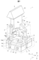
- FIG. 1 is a perspective view of a switch device in an embodiment.
- FIG. 2 is a cross-sectional view of a switch device including a first switch section in the embodiment.
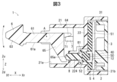
- FIG. 3 is a cross-sectional view of a switch device including a second switch section in the embodiment.
- FIG. 4 is a cross-sectional view of the switch device parallel to the clamping portion in the embodiment.
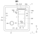
- FIG. 5 is a bottom view of the body in the embodiment.
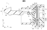
- FIG. 6 is a sectional view of the switch device in the first operating posture in the embodiment.
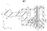
- FIG. 7 is a sectional view of the switch device in the second operating position in the embodiment.
- FIGS. 1 to 7 Embodiments of the present invention will be described with reference to FIGS. 1 to 7.
- the embodiments described below are shown as preferred specific examples for carrying out the present invention, and some portions specifically illustrate various technical matters that are technically preferable. However, the technical scope of the present invention is not limited to this specific embodiment.
- FIG. 1 is a perspective view of a switch device 1 in this embodiment.
- FIG. 2 is a cross-sectional view of the switch device 1 including the first switch section 11.
- FIG. 3 is a sectional view of the switch device 1 including the second switch section 12.
- FIG. 4 is a cross-sectional view of the switch device 1 parallel to the clamping part 10.
- FIG. 5 is a bottom view of the body 2.
- the switch device 1 of this embodiment is assembled into, for example, an instrument panel, a spoke of a steering wheel, a center console, etc. of a vehicle, and is used to operate in-vehicle equipment.
- in-vehicle equipment to be operated by the switch device 1 include air conditioners, audio equipment, etc., and the switch device 1 is used to adjust the temperature, air volume, and direction of the air conditioner, and adjust the volume of the audio equipment. obtain.
- the application of the switch device 1 is not limited to the above-mentioned one, and can be used as a switch for various devices.
- the switch device 1 is a toggle switch that switches on/off states of a first switch section 11 and a second switch section 12 according to rotation of an operation knob 6.
- the switch device 1 of this embodiment includes a body 2, a cover 3, a substrate 4, a contact rubber 5, an operation knob 6, an actuator 7, and a pusher 8.
- FIG. 1 only the outer shape of the body 2 is shown by a chain double-dashed line for convenience.
- the operation knob 6 is rotatable as described later, and the states of the contact rubber 5, actuator 7, and push differ depending on the posture of the operation knob 6. In the following, first, the operation knob 6 is not operated by the user.
- the switch device 1 in a state where it is in a neutral position will be described, and then the operation of the switch device 1 will be described.
- the body 2 holds various parts of the switch device 1.
- the body 2 is made of, for example, resin, and has a cylindrical wall portion 21 and an inner wall portion 22 formed inside the cylindrical wall portion 21 . Both ends of the cylindrical wall portion 21 form openings 21a and 21b.
- the operation knob 6 is assembled into the body 2 through an opening 21a on one side of the cylinder wall 21, and the actuator 7, pusher 8, contact rubber 5, substrate 4, and Cover 3 is assembled.
- a plurality of guide protrusions 211 are formed on the cylindrical wall portion 21 in order to regulate the assembly posture of the contact rubber 5, the substrate 4, and the cover 3 to the body 2.
- a guide recess 13 (see FIG. 1) that fits into the guide protrusion 211 is formed in the cover 3.
- the opening direction of the cylindrical wall portion 21 of the body 2 will be referred to as the front-rear direction X.
- the rear Xr one side in the front-rear direction X where the body 2 is covered by the cover 3
- the opposite side (for example, the side from which the operating knob 6 protrudes from the body 2) is referred to as the front Xf.
- the direction perpendicular to the front-rear direction X and the direction in which the rotation axis A of the operating knob 6 extends is referred to as the left-right direction Y
- the direction perpendicular to both the front-rear direction X and the left-right direction Y is referred to as the up-down direction Z.
- the expressions "front and rear,” “left and right,” and “up and down” do not limit the posture of the switch device 1 when the switch device 1 is in use (for example, when the switch device 1 is mounted on a vehicle).
- cover 3 As shown in FIGS. 2 and 3, the cover 3 is disposed inside the opening 21b at the rear Xr of the cylindrical wall portion 21. As shown in FIGS. The cover 3 supports the actuator 7, pusher 8, contact rubber 5, and substrate 4 arranged inside the body 2 from the side opposite to the inner wall portion 22.
- the cover 3 is made of, for example, resin, and, as shown in FIGS. 1 and 3, is locked to the body 2 at a locking portion 31 formed to project outward.
- a substrate 4 is arranged in front Xf of the cover 3.
- the board 4 is, for example, a printed circuit board on which a wiring pattern (not shown) is formed, and is arranged in the body 2 with its thickness direction in the front-rear direction X.
- the substrate 4 has a first switch section 11 and a second switch section 12 mounted thereon. Two fixed contacts 40 forming the first switch section 11 and the second switch section 12 are formed in the wiring pattern of the substrate 4.
- the wiring pattern of the board 4 is electrically connected to a control section of a device to be operated by the switch device 1 .
- a contact rubber 5 is arranged on the front side Xf of the substrate 4.
- the contact rubber 5 is disposed on the opposite side of the operating knob 6 with the actuator 7 interposed therebetween, and covers substantially the entire front surface of the substrate 4.
- the contact rubber 5 is made of an elastically deformable insulator such as silicone rubber.
- the contact rubber 5 has a flat portion 51 and two rubber domes 52 raised from the flat portion 51.
- the rubber dome 52 is formed in a dome shape and can be elastically deformed in the front-rear direction X.
- the two rubber domes 52 are formed to cover the two fixed contacts 40 on the substrate 4, and a movable contact 50 is provided on the rear surface of the rubber dome 52 at a position facing the fixed contacts 40.
- first switch section 11 and second switch section 12 As shown in FIG. 2, one rubber dome 52, movable contact 50, and fixed contact 40 constitute the first switch section 11, and as shown in FIG. 3, the other rubber dome 52, movable contact 50, and fixed contact 40 constitutes the second switch section 12.
- the first switch section 11 is a switch that is turned on and off via the actuator 7
- the second switch section 12 is a switch that is turned on and off via the pusher 8.
- Each of the first switch section 11 and the second switch section 12 is turned on when the rubber dome 52 is elastically deformed in the front-rear direction X and the movable contact 50 and the fixed contact 40 come into contact, thereby making a predetermined circuit conductive. .
- both the first switch section 11 and the second switch section 12 are unevenly distributed in a region on one side of the respective center positions of the substrate 4 and the contact rubber 5 in the vertical direction Z.
- a lower Zd one side in the vertical direction Z, on which the first switch section 11 and the second switch section 12 are unevenly distributed in the substrate 4 and the contact rubber 5, will be referred to as a lower Zd, and the opposite side will be referred to as an upper Zu.
- the first switch section 11 and the second switch section 12 are arranged at a position further down Zd than the rotation axis A of the operation knob 6.
- the length of the portion above Zu from the rotation axis A is shorter than the length Zd below from the rotation axis A.
- the length of the upper side Zu from the rotation axis A is shorter than the length of the lower side from the rotation axis A. That is, in this embodiment, by unevenly distributing the first switch section 11 and the second switch section 12 downward from the rotation axis A, the portion of the switch device 1 from the rotation axis A to the upper Zu is miniaturized.
- first switch section 11 and the second switch section 12 are arranged straight in the left-right direction Y. Note that the present invention is not limited to this, and the first switch section 11 and the second switch section 12 may be arranged at different positions in the vertical direction Z. Each of the first switch section 11 and the second switch section 12 can be switched between on and off states according to the operation of the operation knob 6.
- the operation knob 6 is a member that is rotatable about a rotation axis A that extends in the left-right direction Y, and is rotated by a user.
- the operation knob 6 has a plate-like main body portion 61, a pair of shaft supports 62, an operation portion 63, an actuator push portion 64, and a pusher push portion 65.
- the plate-shaped main body part 61 is formed on the rotation axis A, and is formed in a plate shape having a thickness in the vertical direction Z.
- the pair of shaft supports 62 protrude from the plate-shaped main body portion 61 on both sides in the left-right direction Y, and are pivotally supported at a portion of the front Xf of the cylindrical wall portion 21 of the body 2 .
- the pair of shaft supports 62 are fixed to the body 2 so that the rotational axis A is at a position Zu above both the first switch section 11 and the second switch section 12.
- the operating portion 63 is provided at the front end of the plate-like main body portion 61 and is a portion that the user touches when rotating the operating knob 6 .
- the operating section 63 is provided so as to be exposed in the vehicle interior.
- the actuator push portion 64 is a portion that pushes the actuator 7 to rotate as the operation knob 6 rotates.
- the actuator push portion 64 is formed to protrude rearward Xr from the plate-like main body portion 61.
- a knob recess 611 recessed upward Zu is formed in one corner of the rear end of the plate-like main body 61, and the actuator pusher 64 has a knob recess 611 formed in the plate-like main body 61. It extends from the part to the rear Xr.
- the lower surface 64a of the actuator push portion 64 is offset upward Zu from the lower surface 61a of the plate-like main body portion 61.
- the lower surface 64a of the actuator push portion 64 is inclined toward the rear Xr and upward Zu.
- the pusher pressing portion 65 is a portion that presses the pusher 8 as the operating knob 6 rotates.
- the pusher pressing portion 65 is formed to protrude downward Zd from the plate-like main body portion 61, and is formed in a plate shape having a thickness in the left-right direction Y.
- the pusher pressing portion 65 has a cam surface 65a facing the pusher 8.
- the cam surface 65a is inclined toward the rear Xr as it goes downward Zd.
- the actuator 7 is a member that is pushed by the actuator push portion 64 of the operation knob 6 when the operation knob 6 is rotated, rotates in the opposite direction to the operation knob 6, and presses the first switch portion 11.
- the actuator 7 has a first section 71, a second section 72, and a third section 73.
- the first portion 71 is formed in a plate shape orthogonal to the vertical direction Z.
- the first portion 71 is located below the actuator push portion 64 of the operation knob 6 Zd.
- the first portion 71 is a portion that is pushed by the actuator pusher 64 as the operating knob 6 rotates.
- the corner between the upper Zu surface and the front Xf surface of the first portion 71 is formed into a curved shape.
- the second portion 72 extends downward Zd from the rear end Xr of the first portion 71, and is formed in a plate shape orthogonal to the front-rear direction X.
- the second portion 72 is formed along the front surface of the rubber dome 52. The second portion 72 pushes the rubber dome 52 as the operating knob 6 rotates.
- the third part 73 has an inclined part 731 extending obliquely upward and backward from the boundary between the first part 71 and the second part 72, and a vertical part 732 extending from the upper end of the inclined part 731 toward the upper Zu. However, it is formed along the flat part 51 of the contact rubber 5.
- the third portion 73 is located closer to the flat portion 51 than the second portion 72 in the front-rear direction X (that is, on the rear side Xr).
- the second portion 72 and the third portion 73 of the actuator 7 have a shape that follows the flat portion 51 and the rubber dome 52 of the contact rubber 5, so that the space for arranging the actuator 7 can be reduced.
- the corner between the front surface and the top surface of the vertical portion 732 is chamfered.
- the actuator 7 is disposed in a second portion placement recess 221, a third portion placement recess 222, and an insertion hole 223 formed in the inner wall portion 22 of the body 2.
- the second part arrangement recess 221 is a recess in which the second part 72 of the actuator 7 is arranged
- the third part arrangement recess 222 is a recess in which the third part 73 of the actuator 7 is arranged.
- Each of the second part arrangement recess 221 and the third part arrangement recess 222 is formed such that the rear surface of the inner wall part 22 of the body 2 is recessed.
- the insertion hole 223 is formed to penetrate in the front-rear direction X through a portion of the inner wall portion 22 between the second portion placement recess 221 and the third portion placement recess 222, and is inserted through the first portion 71 of the actuator 7. There is.
- the upper end of the actuator 7 is held in the front-rear direction X by a holding part 10 formed by the body 2 and the contact rubber 5.
- the upper end portion of the actuator 7 serves as a rotation center portion 732a that is the center of rotation of the actuator 7.
- the holding portion 10 includes a body protrusion 23 that protrudes from the bottom surface of the third part arrangement recess 222 toward the rear Xr, and a rubber protrusion 53 that protrudes from the contact rubber 5 toward the front Xf.
- each of the body protrusion 23 and the rubber protrusion 53 is a protrusion extending in the left-right direction Y.
- the length of the rubber protrusion 53 in the left-right direction Y is shorter than the length of the body protrusion 23.
- each of the body protrusion 23 and the rubber protrusion 53 has a protruding portion formed in a curved shape in a cross-sectional view orthogonal to the left-right direction Y.
- the length of the rubber protrusion 53 in the front-rear direction quantity ).
- the configuration of the holding portion 10 is not limited to that described above, and various configurations may be adopted as long as the rotational center portion 732a of the actuator 7 can be held in a rotatable manner.
- the body protrusion 23 and the rubber protrusion 53 are long protrusions, but the present invention is not limited to this.
- the body protrusion 23 may be omitted, and the flat portion of the body 2 may constitute the holding portion 10.
- the rubber protrusion 53 of the contact rubber 5 may be omitted, and the front surface of the flat portion 51 of the contact rubber 5 may constitute the holding portion 10.
- it is preferable to devise the shape of the actuator 7 so that the actuator 7 does not interfere with the contact rubber 5 when the actuator 7 rotates.
- a gap S1 is formed between the third portion 73 of the actuator 7 and the flat portion 51 of the contact rubber 5.
- a gap S2 is formed between the third portion 73 and a portion of the body 2 around the body protrusion 23.
- a gap S3 is formed between the lower end of the second portion 72 of the actuator 7 and the body 2 in the vertical direction Z.
- the actuator 7 has a length in the vertical direction Z from the first portion 71 to the lower end of the actuator 7 (i.e., the lower end surface of the second portion 72). It is longer than the length in the vertical direction Z up to the end surface). This makes it easy to increase the movement of the second portion 72 (that is, the portion that presses the first switch portion 11) in the front-rear direction X when the actuator 7 rotates.
- the second portion 72 has a pair of actuator convex portions 721 that protrude on both sides in the left-right direction Y.
- the pair of actuator convex portions 721 are opposed to the pair of body convex portions 221a formed to protrude in the left-right direction Y in the second part arrangement concave portion 221 of the body 2, so that when the actuator 7 rotates, etc. The inclination of the actuator 7 is suppressed.
- the third part arrangement recess 222 has a pair of enlarged recesses 222a that are formed to expand on both sides in the left-right direction Y. Furthermore, the third portion 73 of the actuator 7 has a pair of collar portions 732b that protrude on both sides in the left-right direction Y at the upper end portion of the vertical portion 732. The surface of the flange portion 732b on the side where the first portion 71 of the actuator 7 is pushed by the operation knob 6 (ie, the lower side Zd) faces the inner surface of the enlarged recessed portion 222a.
- the flange portion 732b and the enlarged recessed portion 222a constitute a restriction mechanism 14 that restricts the actuator 7 from being displaced toward the side pushed by the operation knob 6.
- the configuration of the regulating mechanism 14 is not limited to this, and other configurations may be adopted as long as the actuator 7 can be prevented from being displaced toward the side pushed by the operating knob 6.
- an example is shown in which there are one pair of flange portions 732b and one pair of enlarged recess portions 222a, but the present invention is not limited to this, and for example, there may be one pair of each.
- the flange portion 732b protrudes in the left-right direction Y in the actuator 7
- the flange portion 732b is not limited thereto, and may protrude in the up-down direction Z, for example. You can also set it to Z.
- the regulating mechanism 14 may be configured by providing a recess in the actuator 7 and inserting a convex portion formed on the body 2 into the recess.
- the pusher 8 is a member that is pushed by the pusher pressing portion 65 of the operating knob 6 when the operating knob 6 is rotated, and is displaced rearward Xr to push the second switch portion 12 .
- the pusher 8 is elongated in the front-rear direction X, has a hemispherical front surface, and has a flange portion 81 protruding toward the outer circumference at the rear end.
- the pusher 8 has a rear surface facing the front surface of the rubber dome 52 constituting the first switch section 11, and a front surface facing the cam surface 65a of the pusher pressing section 65 of the operation knob 6.
- the pusher 8 is inserted into a pusher guide hole 224 formed in the inner wall portion 22 of the body 2 from the rear Xr.
- the flange portion 81 prevents the pusher 8 from falling out from the pusher guide hole 224 toward the front Xf.
- the operating knob 6 is configured to be able to take a neutral attitude shown in FIGS. 2 and 3, a first operating attitude shown in FIG. 6, and a second operating attitude shown in FIG. 7 by rotating.
- FIG. 6 is a sectional view through the first switch section 11 of the switch device 1 with the operation knob 6 in the first operation posture.
- FIG. 7 is a sectional view through the second switch section 12 of the switch device 1 with the operation knob 6 in the second operation posture.
- the external shapes of the operating knob 6 and the actuator 7 when the operating knob 6 is in the neutral attitude are shown by two-dot chain lines, and in FIG.
- the external shapes of the pusher 6 and the pusher 8 are indicated by two-dot chain lines.
- the neutral attitude is the attitude of the operating knob 6 when no external force is applied to the operating knob 6.
- the movable contact 50 and the fixed contact 40 are separated from each other in the first switch part 11 and the second switch part 12, and the first switch part 11 and the second switch part 12 are separated from each other. 12 are both turned off.
- the operating knob 6 is in a position other than the neutral position, when the external force on the operating unit 63 is released, the operating knob 6 is biased to return to the neutral position.
- the first operating posture is a posture in which the operating knob 6 is rotated so that the operating section 63 faces upward Zu from the neutral posture, and the actuator 7 pushes the first switch section 11 to turn it on.
- the rotation direction of the operation knob 6 when the operation knob 6 moves from the neutral posture to the first operation posture will be referred to as a first rotation direction C1
- the direction opposite to the first rotation direction C1 will be referred to as a second rotation direction. It's called C2.
- the actuator 7 When the operation knob 6 rotates from the neutral position to the first operation position, the actuator 7 is pushed by the actuator push part 64 of the operation knob 6, and the rotation direction of the operation knob 6 about the rotation center 732a is It rotates in the opposite direction (ie, second rotation direction C2). At this time, the rubber dome 52 constituting the first switch section 11 is elastically deformed so as to be displaced backward Xr, and eventually the movable contact 50 and the fixed contact 40 constituting the first switch section 11 come into contact and conduction. On the other hand, during this operation, the pusher pressing part 65 of the operating knob 6 moves away from the pusher 8 toward the front Xf, so the second switch part 12 remains in the off state. As described above, when the operation knob 6 is in the first operation posture, only the first switch section 11 of the first switch section 11 and the second switch section 12 is turned on.
- the holding portion 10 only needs to hold the rotation center portion 732a of the actuator 7 at least when the operation knob 6 is in the neutral position.
- a backward force may be applied from the actuator 7 to the rubber protrusion 53, but this force elastically compresses the rubber protrusion 53 in the front-rear direction X.
- the actuator 7 may be separated from the body protrusion 23.
- the rubber dome 52 constituting the first switch section 11 biases the second portion 72 of the actuator 7 toward the front Xf due to its elastic restoring force. are doing. Therefore, when the external force on the operating portion 63 is released from the state where the operating knob 6 is in the first operating posture, the rubber dome 52 elastically restores itself and the actuator 7 is rotated to return to the first rotation direction C1. At the same time, the operation knob 6 is pushed by the first portion 71 of the actuator 7 and rotated back to the second rotation direction C2, and the operation knob 6 returns to the neutral position.
- the second operating posture is a posture in which the operating knob 6 is rotated so that the operating section 63 faces downward Zd from the neutral posture, and the pusher 8 presses the second switch section 12 to turn it on. .
- the pusher 8 is pushed by the cam surface 65a of the pusher pressing portion 65 of the operating knob 6 and is displaced backward Xr.
- the rubber dome 52 constituting the second switch section 12 is elastically deformed so as to be displaced backward Xr, and eventually the movable contact 50 and the fixed contact 40 constituting the second switch section 12 come into contact and conduction.
- the rubber dome 52 constituting the second switch section 12 urges the pusher 8 toward the front Xf by its elastic restoring force. Therefore, when the external force on the operating portion 63 is released from the state where the operating knob 6 is in the second operating posture, the rubber dome 52 is elastically restored, the pusher 8 is displaced to return to the front direction Xf, and the pusher 8 , the operating knob 6 is rotated to return to the first rotation direction C1, and the operating knob 6 returns to the neutral position. As described above, the switch device 1 operates.
- the device to be operated by the switch device 1 is configured to be able to execute predetermined processing depending on the states of the first switch section 11 and the second switch section 12.
- the air conditioner is configured such that the first switch section 11 is in the on state.
- the set air volume may be increased when the second switch section 12 is turned on, and the set air volume may be lowered when the second switch section 12 is turned on.
- the switch device 1 of this embodiment includes a clamping portion 10 that clamps a rotation center portion 732a that is the center of rotation of the actuator 7. Therefore, the rotating actuator 7 can be supported with a simple configuration.
- the switch device 1 also includes a contact rubber 5 that is disposed on the opposite side of the operation knob 6 with the actuator 7 in between and covers the substrate 4 , and the contact rubber 5 constitutes a holding portion 10 .
- the actuator 7 rotates, the actuator 7 is supported by at least the contact rubber 5.
- the actuator 7 is supported when the actuator 7 rotates. It is possible to suppress rattling and noise generation.
- the contact rubber 5 has a rubber protrusion 53 that protrudes toward the rotation center portion 732a and constitutes the holding portion 10. Thereby, it is possible to prevent the actuator 7 from interfering with the contact rubber 5 when the actuator 7 rotates, thereby inhibiting the rotation of the actuator 7.
- the contact rubber 5 has a rubber dome 52 constituting the first switch section 11 , and the amount of protrusion of the rubber protrusion 53 from the flat part 51 of the rubber dome 52 is determined by the amount of protrusion of the rubber dome 52 from the flat part 51 . smaller than the amount.
- the third portion 73 is located closer to the flat portion 51 than the second portion 72 in the thickness direction of the flat portion 51 . Therefore, the actuator 7 can be shaped to follow the surface of the contact rubber 5, and the space for arranging the actuator 7 can be reduced. Thereby, it becomes possible to achieve further miniaturization of the switch device 1.
- the body 2 has a body protrusion 23 that protrudes toward the contact rubber 5 side and constitutes the holding portion 10 . Thereby, it is possible to suppress rattling and noise from occurring due to the actuator 7 interfering with the body 2 when the actuator 7 rotates.
- the switch device 1 includes a first switch section 11 and a second switch section 12, and both of the first switch section 11 and the second switch section 12 are arranged in a first direction in the vertical direction Z with respect to the rotation axis A. It is unevenly distributed on the side (that is, lower Zd). Thereby, in the switch device 1, it is possible to realize miniaturization of the portion on the side opposite to the side where the first switch section 11 and the second switch section 12 are unevenly distributed (that is, the upper Zu).
- the switch device 1 is configured such that when the operation knob 6 is rotated so that the operation section 63 of the operation knob 6 faces downward Zd, the operation knob 6 When the user presses the second switch section 12 and the operating knob 6 is rotated so that the operating section 63 faces upward Zu, the actuator 7 is configured to push the switch section.
- the lower surface 64a of the actuator pushing portion 64 that presses the actuator 7 in the operation knob 6 is offset upward Zu from the lower surface 61a of the plate-like main body portion 61. Therefore, the position of the first portion 71, which is the portion of the actuator 7 that is pressed by the operating knob 6, can be set to the upper Zu position in the switch device 1. Thereby, the entire actuator 7 can be disposed at a relatively upper position Zu in the switch device 1, and it is possible to suppress the portion of the entire switch device 1 below the rotation axis A from increasing in size.
- the actuator 7 has a regulating mechanism 14 that regulates displacement toward the side pushed by the operating knob 6. Therefore, when the actuator 7 is pushed by the operation knob 6, it can be suppressed from being displaced from the desired position.
Landscapes
- Tumbler Switches (AREA)
- Rotary Switch, Piano Key Switch, And Lever Switch (AREA)
Abstract
スイッチ装置1は、スイッチ部11と、回転軸Aを中心に回動可能な操作ノブ6と、操作ノブ6の回動時に操作ノブ6に押されて操作ノブ6の回動方向C1とは反対方向C2に回動しつつスイッチ部11を押すアクチュエータ7と、アクチュエータ7の回動の中心となる回動中心部732aを挟持する挟持部10と、を備える。
Description
本出願は、2022年8月5日に出願された日本国特許出願2022-125327号の優先権を主張するものであり、日本国特許出願2022-125327号の全内容を本出願に参照により援用する。
本発明は、スイッチ装置に関する。
特許文献1には、車両の暖房、換気及び空調(HVAC)システムのヒューマンインタフェース(HMI)として用いられているトグルボタンアセンブリが開示されている。特許文献1に記載のトグルボタンアセンブリは、ユーザによって回転操作されるトグル本体と、第1及び第2のスイッチと、第1及び第2のスイッチアクチュエータとを備える。第1のスイッチアクチュエータは、ユーザによってトグル本体が中立位置から一方側へ回転操作されたとき、トグル本体に押されてトグル本体と反対方向に回転しつつ第1のスイッチを作動させる。第2のスイッチアクチュエータは、ユーザによってトグル本体が中立位置から他方側に回転操作されたとき、トグル本体に押されてトグル本体と反対方向に回転しつつ第2のスイッチを作動させる。第1及び第2のスイッチアクチュエータは、第1及び第2のスイッチアクチュエータ回転シャフトに軸支されている。
特許文献1に記載のトグルボタンアセンブリにおいては、第1及び第2のスイッチアクチュエータを回転可能に支持するために、シャフト部材(すなわち第1及び第2のスイッチアクチュエータ回転シャフト)を用いている。それゆえ、第1及び第2のスイッチアクチュエータを支持するための構造が複雑化しやすい。
本発明の目的は、前述の事情に鑑みてなされたものであり、アクチュエータの支持構造を簡素化することができるスイッチ装置を提供することにある。
本発明の一実施形態によるスイッチ装置は、スイッチ部と、回転軸を中心に回動可能な操作ノブと、前記操作ノブの回動時に前記操作ノブに押されて前記操作ノブの回動方向とは反対方向に回動しつつ前記スイッチ部を押すアクチュエータと、前記アクチュエータの回動の中心となる回動中心部を挟持する挟持部と、を有する。
本発明の一実施形態によれば、アクチュエータの支持構造を簡素化することができるスイッチ装置を提供することが可能となる。
[実施の形態]
本発明の実施の形態について、図1乃至図7を参照して説明する。なお、以下に説明する実施の形態は、本発明を実施する上での好適な具体例として示すものであり、技術的に好ましい種々の技術的事項を具体的に例示している部分もあるが、本発明の技術的範囲は、この具体的態様に限定されるものではない。
本発明の実施の形態について、図1乃至図7を参照して説明する。なお、以下に説明する実施の形態は、本発明を実施する上での好適な具体例として示すものであり、技術的に好ましい種々の技術的事項を具体的に例示している部分もあるが、本発明の技術的範囲は、この具体的態様に限定されるものではない。
(スイッチ装置1)
図1は、本形態におけるスイッチ装置1の斜視図である。図2は、第1スイッチ部11を含むスイッチ装置1の断面図である。図3は、第2スイッチ部12を含むスイッチ装置1の断面図である。図4は、挟持部10に平行なスイッチ装置1の断面図である。図5は、ボディ2の底面図である。
図1は、本形態におけるスイッチ装置1の斜視図である。図2は、第1スイッチ部11を含むスイッチ装置1の断面図である。図3は、第2スイッチ部12を含むスイッチ装置1の断面図である。図4は、挟持部10に平行なスイッチ装置1の断面図である。図5は、ボディ2の底面図である。
本形態のスイッチ装置1は、一例として、車両のインストルメントパネル、ステアリングホイールのスポーク、センターコンソール等に組み付けられ、車載機器の操作に供される。スイッチ装置1の操作対象となる車載機器としては、例えば空調機器、音響機器等があり、スイッチ装置1は、空調機器の温度調整、風量調整、風向調整や、音響機器の音量調整等に供され得る。なお、スイッチ装置1の用途は前述のものに限られず、種々の機器のスイッチとして使用し得る。
スイッチ装置1は、操作ノブ6の回動に応じて第1スイッチ部11及び第2スイッチ部12のオンオフ状態を切り替えるトグルスイッチである。本形態のスイッチ装置1は、ボディ2、カバー3、基板4、コンタクトラバー5、操作ノブ6、アクチュエータ7及びプッシャ8を有する。なお、図1に関し、便宜上ボディ2は外形のみを二点鎖線で表している。また、操作ノブ6は後述するように回動可能であり、操作ノブ6の姿勢によってコンタクトラバー5、アクチュエータ7及びプッシュの状態が異なるが、以下においては、まず操作ノブ6がユーザによって操作されていない中立姿勢にある状態のスイッチ装置1について説明し、その後スイッチ装置1の動作について説明する。
(ボディ2)
図2及び図3に示すごとく、ボディ2は、スイッチ装置1の各種部品を保持している。ボディ2は、例えば樹脂等からなり、筒状に形成された筒壁部21と、筒壁部21の内側に形成された内側壁部22とを有する。筒壁部21の両端部は、開口部21a,21bとなっている。ボディ2内には、筒壁部21の一方側の開口部21aから操作ノブ6が組み付けられ、筒壁部21の他方側の開口部21bからアクチュエータ7、プッシャ8、コンタクトラバー5、基板4及びカバー3が組み付けられる。ボディ2へのコンタクトラバー5、基板4及びカバー3の組付姿勢を規制すべく、筒壁部21にはガイド凸部211(図5参照)が複数形成されており、コンタクトラバー5、基板4及びカバー3にはガイド凸部211に嵌合するガイド凹部13(図1参照)が形成されている。
図2及び図3に示すごとく、ボディ2は、スイッチ装置1の各種部品を保持している。ボディ2は、例えば樹脂等からなり、筒状に形成された筒壁部21と、筒壁部21の内側に形成された内側壁部22とを有する。筒壁部21の両端部は、開口部21a,21bとなっている。ボディ2内には、筒壁部21の一方側の開口部21aから操作ノブ6が組み付けられ、筒壁部21の他方側の開口部21bからアクチュエータ7、プッシャ8、コンタクトラバー5、基板4及びカバー3が組み付けられる。ボディ2へのコンタクトラバー5、基板4及びカバー3の組付姿勢を規制すべく、筒壁部21にはガイド凸部211(図5参照)が複数形成されており、コンタクトラバー5、基板4及びカバー3にはガイド凸部211に嵌合するガイド凹部13(図1参照)が形成されている。
以後、ボディ2の筒壁部21の開口方向を前後方向Xという。また、前後方向Xの一方側であって、ボディ2がカバー3に覆われる側を後方Xrとし、その反対側(例えばボディ2から操作ノブ6が突出する側)を前方Xfとする。また、前後方向Xに直交する方向であって、操作ノブ6の回転軸Aが伸びる方向を左右方向Yといい、前後方向Xと左右方向Yとの双方に直交する方向を上下方向Zという。なお、前後、左右、上下の表現は、スイッチ装置1の使用状態(例えばスイッチ装置1が車載された状態)におけるスイッチ装置1の姿勢を限定するものではない。
(カバー3)
図2及び図3に示すごとく、カバー3は、筒壁部21の後方Xrの開口部21bの内側に配されている。カバー3は、ボディ2内に配されたアクチュエータ7、プッシャ8、コンタクトラバー5及び基板4を、内側壁部22と反対側から支承している。カバー3は、例えば樹脂等からなり、図1及び図3に示すごとく、外方に突出するよう形成された係止部31にてボディ2に係止されている。カバー3の前方Xfに、基板4が配されている。
図2及び図3に示すごとく、カバー3は、筒壁部21の後方Xrの開口部21bの内側に配されている。カバー3は、ボディ2内に配されたアクチュエータ7、プッシャ8、コンタクトラバー5及び基板4を、内側壁部22と反対側から支承している。カバー3は、例えば樹脂等からなり、図1及び図3に示すごとく、外方に突出するよう形成された係止部31にてボディ2に係止されている。カバー3の前方Xfに、基板4が配されている。
(基板4)
基板4は、例えば、図示しない配線パターンが形成されたプリント基板であり、厚み方向が前後方向Xとなる姿勢でボディ2内に配されている。基板4は、第1スイッチ部11及び第2スイッチ部12を実装している。基板4の配線パターンには、第1スイッチ部11及び第2スイッチ部12を構成する2つの固定接点40が形成されている。基板4の配線パターンは、スイッチ装置1による操作対象となる機器の制御部に電気的に接続される。基板4の前方Xfには、コンタクトラバー5が配されている。
基板4は、例えば、図示しない配線パターンが形成されたプリント基板であり、厚み方向が前後方向Xとなる姿勢でボディ2内に配されている。基板4は、第1スイッチ部11及び第2スイッチ部12を実装している。基板4の配線パターンには、第1スイッチ部11及び第2スイッチ部12を構成する2つの固定接点40が形成されている。基板4の配線パターンは、スイッチ装置1による操作対象となる機器の制御部に電気的に接続される。基板4の前方Xfには、コンタクトラバー5が配されている。
(コンタクトラバー5)
図2及び図3に示すごとく、コンタクトラバー5は、アクチュエータ7を挟んで操作ノブ6と反対側に配されているとともに、基板4の前面の略全体を覆っている。コンタクトラバー5は、シリコンゴム等の弾性変形可能な絶縁体からなる。コンタクトラバー5は、平坦部51と、平坦部51から隆起した2つのラバードーム52とを有する。ラバードーム52は、ドーム状に形成されており、前後方向Xに弾性変形可能である。2つのラバードーム52は、基板4上の2つの固定接点40を覆うよう形成されており、ラバードーム52の後面には、固定接点40と対向する位置に可動接点50が設けられている。
図2及び図3に示すごとく、コンタクトラバー5は、アクチュエータ7を挟んで操作ノブ6と反対側に配されているとともに、基板4の前面の略全体を覆っている。コンタクトラバー5は、シリコンゴム等の弾性変形可能な絶縁体からなる。コンタクトラバー5は、平坦部51と、平坦部51から隆起した2つのラバードーム52とを有する。ラバードーム52は、ドーム状に形成されており、前後方向Xに弾性変形可能である。2つのラバードーム52は、基板4上の2つの固定接点40を覆うよう形成されており、ラバードーム52の後面には、固定接点40と対向する位置に可動接点50が設けられている。
(第1スイッチ部11及び第2スイッチ部12)
図2に示すごとく、一方のラバードーム52、可動接点50及び固定接点40が第1スイッチ部11を構成しており、図3に示すごとく、他方のラバードーム52、可動接点50及び固定接点40が第2スイッチ部12を構成している。第1スイッチ部11は、アクチュエータ7を介してオンオフ操作がなされるスイッチであり、第2スイッチ部12はプッシャ8を介してオンオフ操作がなされるスイッチである。第1スイッチ部11及び第2スイッチ部12のそれぞれは、ラバードーム52が前後方向Xに弾性変形して可動接点50と固定接点40とが接触することでオン状態となり、所定の回路を導通させる。
図2に示すごとく、一方のラバードーム52、可動接点50及び固定接点40が第1スイッチ部11を構成しており、図3に示すごとく、他方のラバードーム52、可動接点50及び固定接点40が第2スイッチ部12を構成している。第1スイッチ部11は、アクチュエータ7を介してオンオフ操作がなされるスイッチであり、第2スイッチ部12はプッシャ8を介してオンオフ操作がなされるスイッチである。第1スイッチ部11及び第2スイッチ部12のそれぞれは、ラバードーム52が前後方向Xに弾性変形して可動接点50と固定接点40とが接触することでオン状態となり、所定の回路を導通させる。
本形態において、第1スイッチ部11及び第2スイッチ部12の双方は、上下方向Zにおける基板4及びコンタクトラバー5のそれぞれの中央位置よりも一方側の領域に偏在している。以後、上下方向Zの一方側であって、基板4及びコンタクトラバー5において第1スイッチ部11及び第2スイッチ部12が偏在している側を下方Zdとし、その反対側を上方Zuとする。第1スイッチ部11及び第2スイッチ部12は、操作ノブ6の回転軸Aよりも下方Zdに離れた位置に配されている。また、基板4及びコンタクトラバー5のそれぞれは、上下方向Zにおいて、回転軸Aから上方Zuの部位の長さが、回転軸Aから下方Zdの長さよりも短い。また、スイッチ装置1の全体は、上下方向Zにおいて、回転軸Aから上方Zuの長さが、回転軸Aから下側の長さよりも短い。つまり、本形態においては、第1スイッチ部11及び第2スイッチ部12を回転軸Aから下方Zdに偏在させることで、スイッチ装置1における回転軸Aから上方Zuの部位を小型化している。
本形態において、第1スイッチ部11及び第2スイッチ部12は、左右方向Yにまっすぐ並んでいる。なお、これに限られず、第1スイッチ部11及び第2スイッチ部12は、上下方向Zの互いに異なる位置に配されていてもよい。第1スイッチ部11及び第2スイッチ部12のそれぞれは、操作ノブ6を操作に応じてオンオフ状態が切り替えられる。
(操作ノブ6)
図1乃至図3に示すごとく、操作ノブ6は、左右方向Yに延在する回転軸Aを中心に回動可能であり、ユーザによって回動操作される部材である。操作ノブ6は、板状本体部61、一対の軸支部62、操作部63、アクチュエータ押部64及びプッシャ押部65を有する。
図1乃至図3に示すごとく、操作ノブ6は、左右方向Yに延在する回転軸Aを中心に回動可能であり、ユーザによって回動操作される部材である。操作ノブ6は、板状本体部61、一対の軸支部62、操作部63、アクチュエータ押部64及びプッシャ押部65を有する。
板状本体部61は、回転軸A上に形成されており、上下方向Zに厚みを有する板状に形成されている。一対の軸支部62は、板状本体部61から左右方向Yの両側に突出しており、ボディ2の筒壁部21の前方Xfの部位に軸支されている。一対の軸支部62は、回転軸Aの位置が、第1スイッチ部11及び第2スイッチ部12の双方よりも上方Zuの位置となるようボディ2に固定されている。
操作部63は、板状本体部61の前端部に設けられており、ユーザが操作ノブ6を回動操作する際に触れる部位である。例えばスイッチ装置1が車載機器の操作に供される場合、操作部63は車室に露出するよう設けられる。
アクチュエータ押部64は、操作ノブ6の回動に伴ってアクチュエータ7を押して回動させる部位である。アクチュエータ押部64は、板状本体部61から後方Xrに突出するよう形成されている。本形態において、板状本体部61における後端部の一角には、上方Zuに凹んだノブ凹部611が形成されており、アクチュエータ押部64は、板状本体部61におけるノブ凹部611が形成された部位から後方Xrに延設されている。アクチュエータ押部64の下面64aは、板状本体部61の下面61aから上方Zuにオフセットしている。アクチュエータ押部64の下面64aは、後方Xrに向かうにつれて上方Zuに向かうよう傾斜している。
プッシャ押部65は、操作ノブ6の回動に伴ってプッシャ8を押す部位である。プッシャ押部65は、板状本体部61から下方Zdに突出するよう形成されているとともに、左右方向Yに厚みを有する板状に形成されている。プッシャ押部65は、プッシャ8に対向するカム面65aを有する。カム面65aは、下方Zdに向かうほど後方Xrに向かうよう傾斜している。
(アクチュエータ7)
アクチュエータ7は、操作ノブ6の回動時に操作ノブ6のアクチュエータ押部64に押されて操作ノブ6とは反対方向に回動するとともに第1スイッチ部11を押す部材である。
アクチュエータ7は、操作ノブ6の回動時に操作ノブ6のアクチュエータ押部64に押されて操作ノブ6とは反対方向に回動するとともに第1スイッチ部11を押す部材である。
図2に示すごとく、アクチュエータ7は、第1部位71、第2部位72及び第3部位73を有する。第1部位71は、上下方向Zに直交する板状に形成されている。第1部位71は、操作ノブ6のアクチュエータ押部64の下方Zdに位置している。第1部位71は、操作ノブ6の回動に伴ってアクチュエータ押部64によって押される部位である。操作ノブ6及びアクチュエータ7の回動をスムーズにすべく、第1部位71の上方Zuの面と前方Xfの面との間の角部は曲面状に形成されている。
第2部位72は、第1部位71の後方Xrの端部から下方Zdに延設されており、前後方向Xに直交する板状に形成されている。第2部位72は、ラバードーム52の前面に沿って形成されている。第2部位72は、操作ノブ6の回動に伴ってラバードーム52を押す。
第3部位73は、第1部位71と第2部位72との境界部から斜め上後方に延びた傾斜部731と、傾斜部731の上端から上方Zuに向かって延びた縦部732とを有し、コンタクトラバー5の平坦部51に沿って形成されている。第3部位73は、前後方向Xにおいて、第2部位72よりも平坦部51に近い側(すなわち後方Xr)に位置している。これにより、アクチュエータ7の第2部位72及び第3部位73は、コンタクトラバー5の平坦部51及びラバードーム52に沿った形状となる結果、アクチュエータ7の配置スペースを小さくすることができる。また、アクチュエータ7の回動をスムーズにすべく、縦部732の前面と上面との間の角部は面取りされている。
図2及び図5に示すごとく、アクチュエータ7は、ボディ2の内側壁部22に形成された第2部位配置凹部221、第3部位配置凹部222及び挿通穴223に配されている。第2部位配置凹部221は、アクチュエータ7の第2部位72を配置する凹部であり、第3部位配置凹部222は、アクチュエータ7の第3部位73を配置する凹部である。第2部位配置凹部221及び第3部位配置凹部222のそれぞれは、ボディ2の内側壁部22の後面が凹むようにして形成されている。挿通穴223は、内側壁部22における第2部位配置凹部221と第3部位配置凹部222との間の部位を前後方向Xに貫通するよう形成され、アクチュエータ7の第1部位71を挿通している。
図2に示すごとく、アクチュエータ7の上端部は、ボディ2とコンタクトラバー5とによって構成される挟持部10にて前後方向Xに挟持されている。これにより、アクチュエータ7の上端部は、アクチュエータ7の回動の中心となる回動中心部732aとなっている。挟持部10は、第3部位配置凹部222の底面から後方Xrに突出したボディ突起部23と、コンタクトラバー5から前方Xfに突出したラバー突起部53とによって構成されている。図4及び図5に示すごとく、本形態において、ボディ突起部23及びラバー突起部53のそれぞれは、左右方向Yに延在する突条である。また、本形態において、ラバー突起部53の左右方向Yの長さは、ボディ突起部23の長さより短い。図2に示すごとく、ボディ突起部23及びラバー突起部53のそれぞれは、左右方向Yに直交する断面視において、突出側の部位が湾曲線状に形成されている。ラバー突起部53の前後方向Xの長さ(すなわち平坦部51からのラバー突起部53の突出量)は、ラバードーム52の前後方向Xの長さ(すなわち平坦部51からのラバードーム52の突出量)よりも小さい。
なお、挟持部10の構成は、前述したものに限られず、アクチュエータ7の回動中心部732aを回動可能に挟持可能であれば種々の構成を採用し得る。例えば、本形態においては、ボディ突起部23及びラバー突起部53の双方が長尺な突条である例を示したがこれに限られない。また、例えば、ボディ突起部23を省略し、ボディ2の平面部分が挟持部10を構成してもよい。また、コンタクトラバー5のラバー突起部53を省略し、コンタクトラバー5の平坦部51の前面が挟持部10を構成してもよい。この場合、アクチュエータ7が回動する際にアクチュエータ7がコンタクトラバー5に干渉しないようアクチュエータ7の形状等を工夫することが好ましい。
図2に示すごとく、アクチュエータ7の第3部位73とコンタクトラバー5の平坦部51との間には、隙間S1が形成される。また、第3部位73とボディ2におけるボディ突起部23周囲の部位との間には隙間S2が形成される。さらに、アクチュエータ7の第2部位72の下端部とボディ2との上下方向Zの間には隙間S3が形成されている。これら隙間S1,S2,S3により、アクチュエータ7の回動が阻害され難くなっている。なお、ラバー突起部53がなく、前述の隙間S1がない場合は、例えばコンタクトラバー5に凹み又は穴を設けてアクチュエータ7の回動時にアクチュエータ7がコンタクトラバー5に干渉しないよう構成してもよい。或いは、コンタクトラバー5におけるアクチュエータ7が当たり得る箇所を比較的柔らかく構成することでアクチュエータ7の回動を許容してもよい。
アクチュエータ7は、第1部位71からアクチュエータ7の下端(すなわち第2部位72の下端面)までの上下方向Zの長さが、第1部位71からアクチュエータ7の上端(すなわち第3部位73の上端面)までの上下方向Zの長さよりも長くなっている。これにより、アクチュエータ7の回動時における第2部位72(すなわち第1スイッチ部11を押す部位)の前後方向Xの動作を大きくしやすい。
図5に示すごとく、第2部位72は、左右方向Yの両側に突出した一対のアクチュエータ凸部721を有する。一対のアクチュエータ凸部721は、ボディ2の第2部位配置凹部221において左右方向Yに突出するよう形成された一対のボディ凸部221aと対向しており、これによってアクチュエータ7の回動時等におけるアクチュエータ7の傾きが抑制されている。
また、第3部位配置凹部222は、左右方向Yの両側に広がるよう形成された一対の拡大凹部222aを有する。さらに、アクチュエータ7の第3部位73は、縦部732の上端部に、左右方向Yの両側に突出した一対の鍔部732bを有する。鍔部732bは、アクチュエータ7の第1部位71が操作ノブ6に押される側(すなわち下方Zd)の面が、拡大凹部222aの内面と対向している。これにより、鍔部732b及び拡大凹部222aは、アクチュエータ7が操作ノブ6に押される側に変位することを規制する規制機構14を構成している。なお、規制機構14の構成はこれに限られず、アクチュエータ7が操作ノブ6に押される側に変位することを規制できれば他の構成を採用することも可能である。例えば、本形態においては、鍔部732b及び拡大凹部222aが一対ずつある例を示したが、これに限られず、例えばそれぞれ1つずつであってもよい。また、鍔部732bはアクチュエータ7において左右方向Yに突出している例を示したが、これに限られず例えば上下方向Zに突出していてもよく、これに応じて拡大凹部222aの形成方向も上下方向Zにしてもよい。また、アクチュエータ7に凹みを設け、この凹みにボディ2に形成した凸部を挿入することで規制機構14を構成してもよい。
(プッシャ8)
プッシャ8は、操作ノブ6の回動時に操作ノブ6のプッシャ押部65に押されて後方Xrに変位し、第2スイッチ部12を押す部材である。
プッシャ8は、操作ノブ6の回動時に操作ノブ6のプッシャ押部65に押されて後方Xrに変位し、第2スイッチ部12を押す部材である。
図3に示すごとく、プッシャ8は、前後方向Xに長尺に形成されており、前面が半球面状に形成され、後端部に外周側に突出したフランジ部81を有する。プッシャ8は、後面が第1スイッチ部11を構成するラバードーム52の前面と対向しており、前面が操作ノブ6のプッシャ押部65のカム面65aと対向している。プッシャ8は、ボディ2の内側壁部22に形成されたプッシャ案内穴224に後方Xrから挿入されている。フランジ部81は、プッシャ8がプッシャ案内穴224から前方Xfへ抜け落ちることを防止している。
(スイッチ装置1の動作)
次にスイッチ装置1の動作について説明する。操作ノブ6は、回動することで、図2及び図3に示す中立姿勢、図6に示す第1操作姿勢、及び図7に示す第2操作姿勢となることができるよう構成されている。図6は、操作ノブ6が第1操作姿勢にある状態のスイッチ装置1の、第1スイッチ部11を通る断面図である。図7は、操作ノブ6が第2操作姿勢にある状態のスイッチ装置1の、第2スイッチ部12を通る断面図である。なお、図6において、操作ノブ6が中立姿勢にあるときの操作ノブ6及びアクチュエータ7の外形を二点鎖線にて表しており、図7において、操作ノブ6が中立姿勢にあるときの操作ノブ6及びプッシャ8の外形を二点鎖線にて表している。
次にスイッチ装置1の動作について説明する。操作ノブ6は、回動することで、図2及び図3に示す中立姿勢、図6に示す第1操作姿勢、及び図7に示す第2操作姿勢となることができるよう構成されている。図6は、操作ノブ6が第1操作姿勢にある状態のスイッチ装置1の、第1スイッチ部11を通る断面図である。図7は、操作ノブ6が第2操作姿勢にある状態のスイッチ装置1の、第2スイッチ部12を通る断面図である。なお、図6において、操作ノブ6が中立姿勢にあるときの操作ノブ6及びアクチュエータ7の外形を二点鎖線にて表しており、図7において、操作ノブ6が中立姿勢にあるときの操作ノブ6及びプッシャ8の外形を二点鎖線にて表している。
図2及び図3に示すごとく、中立姿勢は、操作ノブ6に外力が加わっていないときの操作ノブ6の姿勢である。操作ノブ6が中立姿勢にあるときは、第1スイッチ部11及び第2スイッチ部12のそれぞれにおいて、可動接点50と固定接点40とが離隔しており、第1スイッチ部11及び第2スイッチ部12の双方がオフ状態となる。また、後述するように、操作ノブ6が中立姿勢以外にある場合において、操作部63への外力が解除されたとき、操作ノブ6は、中立姿勢に戻るよう付勢されている。
図6に示すごとく、第1操作姿勢は、中立姿勢から操作部63が上方Zuに向かうよう操作ノブ6が回動操作され、アクチュエータ7が第1スイッチ部11を押してオン状態とする姿勢である。以後、操作ノブ6が中立姿勢から第1操作姿勢へ向かう際の操作ノブ6の回動方向を第1回動方向C1といい、第1回動方向C1とは反対方向を第2回動方向C2という。操作ノブ6が中立姿勢から第1操作姿勢へ回動する際、アクチュエータ7は、操作ノブ6のアクチュエータ押部64に押され、回動中心部732aを中心に操作ノブ6の回動方向とは反対方向(すなわち第2回動方向C2)に回動する。このとき、第1スイッチ部11を構成するラバードーム52が後方Xrに変位するよう弾性変形し、やがて第1スイッチ部11を構成する可動接点50と固定接点40とが接触導通する。一方、この動作の際、操作ノブ6のプッシャ押部65は、プッシャ8から前方Xfへ向かって離れるように動作するため、第2スイッチ部12はオフ状態のままとなる。以上により、操作ノブ6が第1操作姿勢にあるとき、第1スイッチ部11及び第2スイッチ部12のうちの第1スイッチ部11のみがオン状態となる。
ここで、挟持部10は、少なくとも操作ノブ6が中立姿勢にあるときにアクチュエータ7の回動中心部732aを挟持していればよい。例えば、操作ノブ6が第1操作姿勢にあるときは、アクチュエータ7からラバー突起部53へ後向きの力が作用し得るが、この力によってラバー突起部53が前後方向Xに弾性的に圧縮されてアクチュエータ7がボディ突起部23から離隔してもよい。
また、操作ノブ6が第1操作姿勢にあるとき、第1スイッチ部11を構成するラバードーム52は、その弾性的な復元力により、アクチュエータ7の第2部位72を前方Xfに向かって付勢している。そのため、操作ノブ6が第1操作姿勢にある状態から操作部63への外力が解除されたとき、ラバードーム52が弾性的に復元し、アクチュエータ7が第1回動方向C1に戻るよう回動するとともに、アクチュエータ7の第1部位71に押されて操作ノブ6が第2回動方向C2に戻るよう回動し、操作ノブ6が中立姿勢に戻る。
図7に示すごとく、第2操作姿勢は、中立姿勢から操作部63が下方Zdに向かうよう操作ノブ6が回動操作され、プッシャ8が第2スイッチ部12を押してオン状態とする姿勢である。操作ノブ6が中立姿勢から第2操作姿勢へ回動する際、プッシャ8は、操作ノブ6のプッシャ押部65のカム面65aに押され、後方Xrに変位する。このとき、第2スイッチ部12を構成するラバードーム52が後方Xrに変位するよう弾性変形し、やがて第2スイッチ部12を構成する可動接点50と固定接点40とが接触導通する。一方、この動作の際、操作ノブ6のアクチュエータ押部64は、アクチュエータ7から上方Zuに離れるように動作するため、第1スイッチ部11はオフ状態のままとなる。これにより、操作ノブ6が第2操作姿勢にあるとき、第1スイッチ部11及び第2スイッチ部12のうちの第2スイッチ部12のみがオン状態となる。
ここで、操作ノブ6が第2操作姿勢にあるとき、第2スイッチ部12を構成するラバードーム52は、その弾性的な復元力により、プッシャ8を前方Xfに向かって付勢している。そのため、操作ノブ6が第2操作姿勢にある状態から操作部63への外力が解除されたとき、ラバードーム52が弾性的に復元し、プッシャ8が前方Xfへ戻るよう変位するとともに、プッシャ8に押されて操作ノブ6が第1回動方向C1に戻るよう回動し、操作ノブ6が中立姿勢に戻る。以上のように、スイッチ装置1が動作する。
スイッチ装置1による操作対象機器は、第1スイッチ部11及び第2スイッチ部12の状態に応じて所定の処理を実行可能に構成されている。一例として、スイッチ装置1の操作対象機器が車両用の空調機器であり、スイッチ装置1が車両用空調機器における風量調整に供される場合、空調機器は、第1スイッチ部11がオン状態となったときに設定風量を上げ、第2スイッチ部12がオン状態となった場合に設定風量を下げるよう処理を実行してもよい。
(実施の形態の作用及び効果)
本形態のスイッチ装置1は、アクチュエータ7の回動の中心となる回動中心部732aを挟持する挟持部10を備える。それゆえ、回動するアクチュエータ7を、簡易な構成にて支持することができる。
本形態のスイッチ装置1は、アクチュエータ7の回動の中心となる回動中心部732aを挟持する挟持部10を備える。それゆえ、回動するアクチュエータ7を、簡易な構成にて支持することができる。
また、スイッチ装置1は、アクチュエータ7を挟んで操作ノブ6と反対側に配されているとともに基板4を覆うコンタクトラバー5を備え、コンタクトラバー5が、挟持部10を構成している。これにより、アクチュエータ7の回動時、アクチュエータ7は少なくともコンタクトラバー5によって支持されることとなるところ、弾性変形可能なコンタクトラバー5にてアクチュエータ7を支持することにより、アクチュエータ7の回動時におけるがたつきや騒音の発生を抑制することができる。
また、コンタクトラバー5は、回動中心部732a側に突出するとともに挟持部10を構成するラバー突起部53を有する。これにより、アクチュエータ7の回動時にアクチュエータ7がコンタクトラバー5に干渉してアクチュエータ7の回動が阻害されることを抑制することができる。
また、コンタクトラバー5は、第1スイッチ部11を構成するラバードーム52を有し、ラバードーム52の平坦部51からのラバー突起部53の突出量は、平坦部51からのラバードーム52の突出量よりも小さい。そして、平坦部51の厚み方向において、第3部位73は、第2部位72よりも平坦部51に近い側に位置している。それゆえ、アクチュエータ7を、コンタクトラバー5の表面に沿った形状とすることができ、アクチュエータ7の配置スペースを小さくすることができる。これにより、スイッチ装置1の一層の小型化を図ることが可能となる。
また、ボディ2は、コンタクトラバー5側に突出するとともに挟持部10を構成するボディ突起部23を有する。これにより、アクチュエータ7の回動時に、アクチュエータ7がボディ2に干渉することでがたつきや騒音が発生することを抑制することができる。
また、スイッチ装置1は、第1スイッチ部11と第2スイッチ部12とを備え、第1スイッチ部11及び第2スイッチ部12の双方は、回転軸Aに対して、上下方向Zの第1側(すなわち下方Zd)に偏在している。これにより、スイッチ装置1において、第1スイッチ部11及び第2スイッチ部12が偏在する側と反対側(すなわち上方Zu)の部位の小型化を実現することができる。かかる第1スイッチ部11及び第2スイッチ部12の偏在を実現するために、スイッチ装置1は、操作ノブ6の操作部63が下方Zdに向かうよう操作ノブ6が回動したとき、操作ノブ6が第2スイッチ部12を押し、操作部63が上方Zuに向かうよう操作ノブ6が回動したとき、アクチュエータ7がスイッチ部を押すよう構成されている。
また、操作ノブ6におけるアクチュエータ7を押すアクチュエータ押部64の下面64aは、板状本体部61の下面61aから、上方Zuにオフセットしている。それゆえ、アクチュエータ7における操作ノブ6におって押される部位である第1部位71の位置を、スイッチ装置1において上方Zuの位置にすることができる。これにより、アクチュエータ7全体をスイッチ装置1において比較的上方Zuの位置に配置することができ、スイッチ装置1全体において回転軸Aから下側の部位が大型化することを抑制することができる。
また、アクチュエータ7は、操作ノブ6にて押される側に変位することを規制する規制機構14を有する。それゆえ、アクチュエータ7が操作ノブ6に押された際に所望の位置から変位することを抑制することができる。
以上のごとく、本形態によれば、アクチュエータの支持構造を簡素化することができるスイッチ装置を提供することができる。
以上、本発明の実施の形態を説明したが、前述した実施の形態は請求の範囲に係る発明を限定するものではない。また、実施の形態の中で説明した特徴の組合せの全てが発明の課題を解決するための手段に必須であるとは限らない点に留意すべきである。また、本発明は、その趣旨を逸脱しない範囲で適宜変形して実施することが可能である。
1 スイッチ装置
10 挟持部
11 第1スイッチ部(スイッチ部)
12 第2スイッチ部
14 規制機構
2 ボディ
4 基板
5 コンタクトラバー
52 ラバードーム
6 操作ノブ
61 板状本体部
61a 板状本体部の下面(板状本体部の第1側の面)
63 操作部
64 アクチュエータ押部
64a アクチュエータ押部の下面(アクチュエータ押部の第1側の面)
7 アクチュエータ
732a 回動中心部
A 回転軸
10 挟持部
11 第1スイッチ部(スイッチ部)
12 第2スイッチ部
14 規制機構
2 ボディ
4 基板
5 コンタクトラバー
52 ラバードーム
6 操作ノブ
61 板状本体部
61a 板状本体部の下面(板状本体部の第1側の面)
63 操作部
64 アクチュエータ押部
64a アクチュエータ押部の下面(アクチュエータ押部の第1側の面)
7 アクチュエータ
732a 回動中心部
A 回転軸
Claims (10)
- スイッチ部と、
回転軸を中心に回動可能な操作ノブと、
前記操作ノブの回動時に前記操作ノブに押されて前記操作ノブの回動方向とは反対方向に回動しつつ前記スイッチ部を押すアクチュエータと、
前記アクチュエータの回動の中心となる回動中心部を挟持する挟持部と、を備える、
スイッチ装置。 - 前記スイッチ部を実装する基板と、
前記アクチュエータを挟んで前記操作ノブと反対側に配されるとともに前記基板を覆うコンタクトラバーと、をさらに備え、
前記コンタクトラバーが、前記挟持部を構成している、
請求項1に記載のスイッチ装置。 - 前記コンタクトラバーは、前記回動中心部側に突出するとともに前記挟持部を構成するラバー突起部を有する、
請求項2に記載のスイッチ装置。 - 前記コンタクトラバーは、前記スイッチ部を構成するラバードームを有し、
前記コンタクトラバーの平坦部からの前記ラバー突起部の突出量は、前記平坦部からの前記ラバードームの突出量よりも小さく、
前記アクチュエータは、前記操作ノブによって押される第1部位と、前記ラバードームに沿って形成されるとともに前記ラバードームを押す第2部位と、前記平坦部に沿って形成されるとともに一端に前記回動中心部を有する第3部位とを備え、
前記平坦部の厚み方向において、前記第3部位は、前記第2部位よりも前記平坦部に近い側に位置している、
請求項3に記載のスイッチ装置。 - 前記操作ノブを保持するボディをさらに有し、
前記ボディは、前記コンタクトラバー側に突出するとともに前記挟持部を構成するボディ突起部を有する、
請求項2乃至4のいずれか1項に記載のスイッチ装置。 - 前記スイッチ部を実装する基板と、
前記基板に実装された第2スイッチ部と、をさらに備え、
前記スイッチ部及び前記第2スイッチ部の双方は、前記回転軸に対して、前記基板の厚み方向及び前記回転軸の軸方向の双方に直交する直交方向の第1側に偏在しており、
前記操作ノブの操作部が前記第1側に向かうよう前記操作ノブが回動したとき、前記操作ノブが前記第2スイッチ部を押し、
前記操作部が前記第1側と反対側である第2側に向かうよう前記操作ノブが回動したとき、前記アクチュエータが前記スイッチ部を押す、
請求項1に記載のスイッチ装置。 - 前記第1スイッチ部及び前記第2スイッチ部は、前記第1側にまっすぐ並んで配されている、
請求項6に記載のスイッチ装置。 - 前記第1スイッチ部及び前記第2スイッチ部は、前記第1側の互いに異なる位置に配されている、
請求項6に記載のスイッチ装置。 - 前記スイッチ部を実装する基板をさらに備え、
前記スイッチ部は、前記回転軸に対して、前記基板の厚み方向及び前記回転軸の軸方向の双方に直交する直交方向の第1側に配されており、
前記操作ノブは、前記回転軸上に形成された板状本体部を有し、
前記操作ノブにおける前記アクチュエータを押すアクチュエータ押部の前記第1側の面は、前記板状本体部の前記第1側の面から、前記第1側と反対側である第2側にオフセットしている、
請求項1に記載のスイッチ装置。 - 前記アクチュエータが、前記操作ノブにて押される側に変位することを規制する規制機構をさらに有する、
請求項1に記載のスイッチ装置。
Applications Claiming Priority (2)
| Application Number | Priority Date | Filing Date | Title |
|---|---|---|---|
| JP2022125327A JP2024022030A (ja) | 2022-08-05 | 2022-08-05 | スイッチ装置 |
| JP2022-125327 | 2022-08-05 |
Publications (1)
| Publication Number | Publication Date |
|---|---|
| WO2024029488A1 true WO2024029488A1 (ja) | 2024-02-08 |
Family
ID=89849322
Family Applications (1)
| Application Number | Title | Priority Date | Filing Date |
|---|---|---|---|
| PCT/JP2023/027943 Ceased WO2024029488A1 (ja) | 2022-08-05 | 2023-07-31 | スイッチ装置 |
Country Status (2)
| Country | Link |
|---|---|
| JP (1) | JP2024022030A (ja) |
| WO (1) | WO2024029488A1 (ja) |
Citations (5)
| Publication number | Priority date | Publication date | Assignee | Title |
|---|---|---|---|---|
| JPS5638936U (ja) * | 1979-09-04 | 1981-04-11 | ||
| JPH09190741A (ja) * | 1996-01-08 | 1997-07-22 | Tokai Rika Co Ltd | スイッチ装置 |
| WO2018147206A1 (ja) * | 2017-02-08 | 2018-08-16 | 株式会社デンソー | スイッチ装置 |
| JP2019121593A (ja) * | 2017-12-29 | 2019-07-22 | 株式会社デンソー | トグルボタンアセンブリ |
| US10879022B1 (en) * | 2019-08-15 | 2020-12-29 | Denso International America, Inc. | Toggle switch |
-
2022
- 2022-08-05 JP JP2022125327A patent/JP2024022030A/ja active Pending
-
2023
- 2023-07-31 WO PCT/JP2023/027943 patent/WO2024029488A1/ja not_active Ceased
Patent Citations (5)
| Publication number | Priority date | Publication date | Assignee | Title |
|---|---|---|---|---|
| JPS5638936U (ja) * | 1979-09-04 | 1981-04-11 | ||
| JPH09190741A (ja) * | 1996-01-08 | 1997-07-22 | Tokai Rika Co Ltd | スイッチ装置 |
| WO2018147206A1 (ja) * | 2017-02-08 | 2018-08-16 | 株式会社デンソー | スイッチ装置 |
| JP2019121593A (ja) * | 2017-12-29 | 2019-07-22 | 株式会社デンソー | トグルボタンアセンブリ |
| US10879022B1 (en) * | 2019-08-15 | 2020-12-29 | Denso International America, Inc. | Toggle switch |
Also Published As
| Publication number | Publication date |
|---|---|
| JP2024022030A (ja) | 2024-02-16 |
Similar Documents
| Publication | Publication Date | Title |
|---|---|---|
| JP5128300B2 (ja) | スイッチ装置 | |
| JP6857778B2 (ja) | スイッチ装置 | |
| EP1760742B1 (en) | Switch device and steering switch apparatus equipped with the switch device | |
| JP5859884B2 (ja) | ステアリングスイッチ装置 | |
| JP7125557B2 (ja) | 操作装置 | |
| CN109994336B (zh) | 切换按钮 | |
| US7960664B2 (en) | Seesaw switch | |
| JP7223770B2 (ja) | 操作装置 | |
| JP2024022030A (ja) | スイッチ装置 | |
| JP2019160457A (ja) | スイッチ及びこれを備えた多方向入力装置 | |
| JP4046107B2 (ja) | 多方向操作スイッチ | |
| JP7267853B2 (ja) | スイッチ装置 | |
| JP4105432B2 (ja) | 多方向入力装置 | |
| JP4299614B2 (ja) | スイッチ | |
| JP2009090948A (ja) | 車両用2段押し下げスイッチ | |
| JP5407636B2 (ja) | 車載用の複合操作スイッチ | |
| KR20170086762A (ko) | 차량 스티어링 시스템의 틸트 및 텔레스코픽 스위치 | |
| JP7143230B2 (ja) | 車両用内装装置 | |
| JP4186612B2 (ja) | 複合操作型電子部品 | |
| CN107644751B (zh) | 操作单元的组装结构 | |
| JP2024178594A (ja) | トグルスイッチ | |
| JP7326388B2 (ja) | スイッチ | |
| JPH10269897A (ja) | 切替スイッチ | |
| CN203260520U (zh) | 组合按键和具有该组合按键的汽车收音机 | |
| JP7240988B2 (ja) | 電子キー |
Legal Events
| Date | Code | Title | Description |
|---|---|---|---|
| 121 | Ep: the epo has been informed by wipo that ep was designated in this application |
Ref document number: 23850043 Country of ref document: EP Kind code of ref document: A1 |
|
| NENP | Non-entry into the national phase |
Ref country code: DE |
|
| 122 | Ep: pct application non-entry in european phase |
Ref document number: 23850043 Country of ref document: EP Kind code of ref document: A1 |