WO2024029353A1 - 圧縮空気貯蔵容器と前記圧縮空気貯蔵容器を含む圧縮空気貯蔵装置 - Google Patents
圧縮空気貯蔵容器と前記圧縮空気貯蔵容器を含む圧縮空気貯蔵装置 Download PDFInfo
- Publication number
- WO2024029353A1 WO2024029353A1 PCT/JP2023/026557 JP2023026557W WO2024029353A1 WO 2024029353 A1 WO2024029353 A1 WO 2024029353A1 JP 2023026557 W JP2023026557 W JP 2023026557W WO 2024029353 A1 WO2024029353 A1 WO 2024029353A1
- Authority
- WO
- WIPO (PCT)
- Prior art keywords
- compressed air
- cylindrical
- air storage
- buffer gas
- container
- Prior art date
- Legal status (The legal status is an assumption and is not a legal conclusion. Google has not performed a legal analysis and makes no representation as to the accuracy of the status listed.)
- Ceased
Links
Images

Classifications
-
- F—MECHANICAL ENGINEERING; LIGHTING; HEATING; WEAPONS; BLASTING
- F02—COMBUSTION ENGINES; HOT-GAS OR COMBUSTION-PRODUCT ENGINE PLANTS
- F02C—GAS-TURBINE PLANTS; AIR INTAKES FOR JET-PROPULSION PLANTS; CONTROLLING FUEL SUPPLY IN AIR-BREATHING JET-PROPULSION PLANTS
- F02C6/00—Plural gas-turbine plants; Combinations of gas-turbine plants with other apparatus; Adaptations of gas-turbine plants for special use
- F02C6/14—Gas-turbine plants having means for storing energy, e.g. for meeting peak loads
- F02C6/16—Gas-turbine plants having means for storing energy, e.g. for meeting peak loads for storing compressed air
-
- F—MECHANICAL ENGINEERING; LIGHTING; HEATING; WEAPONS; BLASTING
- F01—MACHINES OR ENGINES IN GENERAL; ENGINE PLANTS IN GENERAL; STEAM ENGINES
- F01D—NON-POSITIVE DISPLACEMENT MACHINES OR ENGINES, e.g. STEAM TURBINES
- F01D15/00—Adaptations of machines or engines for special use; Combinations of engines with devices driven thereby
- F01D15/10—Adaptations for driving, or combinations with, electric generators
-
- F—MECHANICAL ENGINEERING; LIGHTING; HEATING; WEAPONS; BLASTING
- F17—STORING OR DISTRIBUTING GASES OR LIQUIDS
- F17C—VESSELS FOR CONTAINING OR STORING COMPRESSED, LIQUEFIED OR SOLIDIFIED GASES; FIXED-CAPACITY GAS-HOLDERS; FILLING VESSELS WITH, OR DISCHARGING FROM VESSELS, COMPRESSED, LIQUEFIED, OR SOLIDIFIED GASES
- F17C1/00—Pressure vessels, e.g. gas cylinder, gas tank, replaceable cartridge
-
- F—MECHANICAL ENGINEERING; LIGHTING; HEATING; WEAPONS; BLASTING
- F17—STORING OR DISTRIBUTING GASES OR LIQUIDS
- F17C—VESSELS FOR CONTAINING OR STORING COMPRESSED, LIQUEFIED OR SOLIDIFIED GASES; FIXED-CAPACITY GAS-HOLDERS; FILLING VESSELS WITH, OR DISCHARGING FROM VESSELS, COMPRESSED, LIQUEFIED, OR SOLIDIFIED GASES
- F17C13/00—Details of vessels or of the filling or discharging of vessels
- F17C13/002—Details of vessels or of the filling or discharging of vessels for vessels under pressure
-
- F—MECHANICAL ENGINEERING; LIGHTING; HEATING; WEAPONS; BLASTING
- F17—STORING OR DISTRIBUTING GASES OR LIQUIDS
- F17C—VESSELS FOR CONTAINING OR STORING COMPRESSED, LIQUEFIED OR SOLIDIFIED GASES; FIXED-CAPACITY GAS-HOLDERS; FILLING VESSELS WITH, OR DISCHARGING FROM VESSELS, COMPRESSED, LIQUEFIED, OR SOLIDIFIED GASES
- F17C13/00—Details of vessels or of the filling or discharging of vessels
- F17C13/04—Arrangement or mounting of valves
-
- F—MECHANICAL ENGINEERING; LIGHTING; HEATING; WEAPONS; BLASTING
- F03—MACHINES OR ENGINES FOR LIQUIDS; WIND, SPRING, OR WEIGHT MOTORS; PRODUCING MECHANICAL POWER OR A REACTIVE PROPULSIVE THRUST, NOT OTHERWISE PROVIDED FOR
- F03D—WIND MOTORS
- F03D9/00—Adaptations of wind motors for special use; Combinations of wind motors with apparatus driven thereby; Wind motors specially adapted for installation in particular locations
- F03D9/10—Combinations of wind motors with apparatus storing energy
- F03D9/17—Combinations of wind motors with apparatus storing energy storing energy in pressurised fluids
-
- F—MECHANICAL ENGINEERING; LIGHTING; HEATING; WEAPONS; BLASTING
- F05—INDEXING SCHEMES RELATING TO ENGINES OR PUMPS IN VARIOUS SUBCLASSES OF CLASSES F01-F04
- F05B—INDEXING SCHEME RELATING TO WIND, SPRING, WEIGHT, INERTIA OR LIKE MOTORS, TO MACHINES OR ENGINES FOR LIQUIDS COVERED BY SUBCLASSES F03B, F03D AND F03G
- F05B2220/00—Application
- F05B2220/70—Application in combination with
- F05B2220/706—Application in combination with an electrical generator
-
- F—MECHANICAL ENGINEERING; LIGHTING; HEATING; WEAPONS; BLASTING
- F05—INDEXING SCHEMES RELATING TO ENGINES OR PUMPS IN VARIOUS SUBCLASSES OF CLASSES F01-F04
- F05D—INDEXING SCHEME FOR ASPECTS RELATING TO NON-POSITIVE-DISPLACEMENT MACHINES OR ENGINES, GAS-TURBINES OR JET-PROPULSION PLANTS
- F05D2220/00—Application
- F05D2220/70—Application in combination with
- F05D2220/76—Application in combination with an electrical generator
-
- F—MECHANICAL ENGINEERING; LIGHTING; HEATING; WEAPONS; BLASTING
- F17—STORING OR DISTRIBUTING GASES OR LIQUIDS
- F17C—VESSELS FOR CONTAINING OR STORING COMPRESSED, LIQUEFIED OR SOLIDIFIED GASES; FIXED-CAPACITY GAS-HOLDERS; FILLING VESSELS WITH, OR DISCHARGING FROM VESSELS, COMPRESSED, LIQUEFIED, OR SOLIDIFIED GASES
- F17C2201/00—Vessel construction, in particular geometry, arrangement or size
- F17C2201/01—Shape
- F17C2201/0104—Shape cylindrical
-
- F—MECHANICAL ENGINEERING; LIGHTING; HEATING; WEAPONS; BLASTING
- F17—STORING OR DISTRIBUTING GASES OR LIQUIDS
- F17C—VESSELS FOR CONTAINING OR STORING COMPRESSED, LIQUEFIED OR SOLIDIFIED GASES; FIXED-CAPACITY GAS-HOLDERS; FILLING VESSELS WITH, OR DISCHARGING FROM VESSELS, COMPRESSED, LIQUEFIED, OR SOLIDIFIED GASES
- F17C2201/00—Vessel construction, in particular geometry, arrangement or size
- F17C2201/01—Shape
- F17C2201/0104—Shape cylindrical
- F17C2201/0119—Shape cylindrical with flat end-piece
-
- F—MECHANICAL ENGINEERING; LIGHTING; HEATING; WEAPONS; BLASTING
- F17—STORING OR DISTRIBUTING GASES OR LIQUIDS
- F17C—VESSELS FOR CONTAINING OR STORING COMPRESSED, LIQUEFIED OR SOLIDIFIED GASES; FIXED-CAPACITY GAS-HOLDERS; FILLING VESSELS WITH, OR DISCHARGING FROM VESSELS, COMPRESSED, LIQUEFIED, OR SOLIDIFIED GASES
- F17C2201/00—Vessel construction, in particular geometry, arrangement or size
- F17C2201/01—Shape
- F17C2201/0147—Shape complex
- F17C2201/0157—Polygonal
-
- F—MECHANICAL ENGINEERING; LIGHTING; HEATING; WEAPONS; BLASTING
- F17—STORING OR DISTRIBUTING GASES OR LIQUIDS
- F17C—VESSELS FOR CONTAINING OR STORING COMPRESSED, LIQUEFIED OR SOLIDIFIED GASES; FIXED-CAPACITY GAS-HOLDERS; FILLING VESSELS WITH, OR DISCHARGING FROM VESSELS, COMPRESSED, LIQUEFIED, OR SOLIDIFIED GASES
- F17C2201/00—Vessel construction, in particular geometry, arrangement or size
- F17C2201/01—Shape
- F17C2201/0176—Shape variable
- F17C2201/0185—Shape variable with separating membrane
-
- F—MECHANICAL ENGINEERING; LIGHTING; HEATING; WEAPONS; BLASTING
- F17—STORING OR DISTRIBUTING GASES OR LIQUIDS
- F17C—VESSELS FOR CONTAINING OR STORING COMPRESSED, LIQUEFIED OR SOLIDIFIED GASES; FIXED-CAPACITY GAS-HOLDERS; FILLING VESSELS WITH, OR DISCHARGING FROM VESSELS, COMPRESSED, LIQUEFIED, OR SOLIDIFIED GASES
- F17C2201/00—Vessel construction, in particular geometry, arrangement or size
- F17C2201/03—Orientation
- F17C2201/032—Orientation with substantially vertical main axis
-
- F—MECHANICAL ENGINEERING; LIGHTING; HEATING; WEAPONS; BLASTING
- F17—STORING OR DISTRIBUTING GASES OR LIQUIDS
- F17C—VESSELS FOR CONTAINING OR STORING COMPRESSED, LIQUEFIED OR SOLIDIFIED GASES; FIXED-CAPACITY GAS-HOLDERS; FILLING VESSELS WITH, OR DISCHARGING FROM VESSELS, COMPRESSED, LIQUEFIED, OR SOLIDIFIED GASES
- F17C2201/00—Vessel construction, in particular geometry, arrangement or size
- F17C2201/05—Size
- F17C2201/052—Size large (>1000 m3)
-
- F—MECHANICAL ENGINEERING; LIGHTING; HEATING; WEAPONS; BLASTING
- F17—STORING OR DISTRIBUTING GASES OR LIQUIDS
- F17C—VESSELS FOR CONTAINING OR STORING COMPRESSED, LIQUEFIED OR SOLIDIFIED GASES; FIXED-CAPACITY GAS-HOLDERS; FILLING VESSELS WITH, OR DISCHARGING FROM VESSELS, COMPRESSED, LIQUEFIED, OR SOLIDIFIED GASES
- F17C2201/00—Vessel construction, in particular geometry, arrangement or size
- F17C2201/05—Size
- F17C2201/054—Size medium (>1 m3)
-
- F—MECHANICAL ENGINEERING; LIGHTING; HEATING; WEAPONS; BLASTING
- F17—STORING OR DISTRIBUTING GASES OR LIQUIDS
- F17C—VESSELS FOR CONTAINING OR STORING COMPRESSED, LIQUEFIED OR SOLIDIFIED GASES; FIXED-CAPACITY GAS-HOLDERS; FILLING VESSELS WITH, OR DISCHARGING FROM VESSELS, COMPRESSED, LIQUEFIED, OR SOLIDIFIED GASES
- F17C2203/00—Vessel construction, in particular walls or details thereof
- F17C2203/06—Materials for walls or layers thereof; Properties or structures of walls or their materials
- F17C2203/0634—Materials for walls or layers thereof
- F17C2203/0636—Metals
- F17C2203/0639—Steels
-
- F—MECHANICAL ENGINEERING; LIGHTING; HEATING; WEAPONS; BLASTING
- F17—STORING OR DISTRIBUTING GASES OR LIQUIDS
- F17C—VESSELS FOR CONTAINING OR STORING COMPRESSED, LIQUEFIED OR SOLIDIFIED GASES; FIXED-CAPACITY GAS-HOLDERS; FILLING VESSELS WITH, OR DISCHARGING FROM VESSELS, COMPRESSED, LIQUEFIED, OR SOLIDIFIED GASES
- F17C2203/00—Vessel construction, in particular walls or details thereof
- F17C2203/06—Materials for walls or layers thereof; Properties or structures of walls or their materials
- F17C2203/0634—Materials for walls or layers thereof
- F17C2203/0636—Metals
- F17C2203/0639—Steels
- F17C2203/0643—Stainless steels
-
- F—MECHANICAL ENGINEERING; LIGHTING; HEATING; WEAPONS; BLASTING
- F17—STORING OR DISTRIBUTING GASES OR LIQUIDS
- F17C—VESSELS FOR CONTAINING OR STORING COMPRESSED, LIQUEFIED OR SOLIDIFIED GASES; FIXED-CAPACITY GAS-HOLDERS; FILLING VESSELS WITH, OR DISCHARGING FROM VESSELS, COMPRESSED, LIQUEFIED, OR SOLIDIFIED GASES
- F17C2205/00—Vessel construction, in particular mounting arrangements, attachments or identifications means
- F17C2205/03—Fluid connections, filters, valves, closure means or other attachments
- F17C2205/0302—Fittings, valves, filters, or components in connection with the gas storage device
- F17C2205/0352—Pipes
-
- F—MECHANICAL ENGINEERING; LIGHTING; HEATING; WEAPONS; BLASTING
- F17—STORING OR DISTRIBUTING GASES OR LIQUIDS
- F17C—VESSELS FOR CONTAINING OR STORING COMPRESSED, LIQUEFIED OR SOLIDIFIED GASES; FIXED-CAPACITY GAS-HOLDERS; FILLING VESSELS WITH, OR DISCHARGING FROM VESSELS, COMPRESSED, LIQUEFIED, OR SOLIDIFIED GASES
- F17C2221/00—Handled fluid, in particular type of fluid
- F17C2221/03—Mixtures
- F17C2221/031—Air
-
- F—MECHANICAL ENGINEERING; LIGHTING; HEATING; WEAPONS; BLASTING
- F17—STORING OR DISTRIBUTING GASES OR LIQUIDS
- F17C—VESSELS FOR CONTAINING OR STORING COMPRESSED, LIQUEFIED OR SOLIDIFIED GASES; FIXED-CAPACITY GAS-HOLDERS; FILLING VESSELS WITH, OR DISCHARGING FROM VESSELS, COMPRESSED, LIQUEFIED, OR SOLIDIFIED GASES
- F17C2223/00—Handled fluid before transfer, i.e. state of fluid when stored in the vessel or before transfer from the vessel
- F17C2223/01—Handled fluid before transfer, i.e. state of fluid when stored in the vessel or before transfer from the vessel characterised by the phase
- F17C2223/0107—Single phase
- F17C2223/0123—Single phase gaseous, e.g. CNG, GNC
-
- F—MECHANICAL ENGINEERING; LIGHTING; HEATING; WEAPONS; BLASTING
- F17—STORING OR DISTRIBUTING GASES OR LIQUIDS
- F17C—VESSELS FOR CONTAINING OR STORING COMPRESSED, LIQUEFIED OR SOLIDIFIED GASES; FIXED-CAPACITY GAS-HOLDERS; FILLING VESSELS WITH, OR DISCHARGING FROM VESSELS, COMPRESSED, LIQUEFIED, OR SOLIDIFIED GASES
- F17C2223/00—Handled fluid before transfer, i.e. state of fluid when stored in the vessel or before transfer from the vessel
- F17C2223/03—Handled fluid before transfer, i.e. state of fluid when stored in the vessel or before transfer from the vessel characterised by the pressure level
- F17C2223/036—Very high pressure (>80 bar)
-
- F—MECHANICAL ENGINEERING; LIGHTING; HEATING; WEAPONS; BLASTING
- F17—STORING OR DISTRIBUTING GASES OR LIQUIDS
- F17C—VESSELS FOR CONTAINING OR STORING COMPRESSED, LIQUEFIED OR SOLIDIFIED GASES; FIXED-CAPACITY GAS-HOLDERS; FILLING VESSELS WITH, OR DISCHARGING FROM VESSELS, COMPRESSED, LIQUEFIED, OR SOLIDIFIED GASES
- F17C2227/00—Transfer of fluids, i.e. method or means for transferring the fluid; Heat exchange with the fluid
- F17C2227/01—Propulsion of the fluid
- F17C2227/0128—Propulsion of the fluid with pumps or compressors
- F17C2227/0157—Compressors
-
- F—MECHANICAL ENGINEERING; LIGHTING; HEATING; WEAPONS; BLASTING
- F17—STORING OR DISTRIBUTING GASES OR LIQUIDS
- F17C—VESSELS FOR CONTAINING OR STORING COMPRESSED, LIQUEFIED OR SOLIDIFIED GASES; FIXED-CAPACITY GAS-HOLDERS; FILLING VESSELS WITH, OR DISCHARGING FROM VESSELS, COMPRESSED, LIQUEFIED, OR SOLIDIFIED GASES
- F17C2227/00—Transfer of fluids, i.e. method or means for transferring the fluid; Heat exchange with the fluid
- F17C2227/03—Heat exchange with the fluid
-
- F—MECHANICAL ENGINEERING; LIGHTING; HEATING; WEAPONS; BLASTING
- F17—STORING OR DISTRIBUTING GASES OR LIQUIDS
- F17C—VESSELS FOR CONTAINING OR STORING COMPRESSED, LIQUEFIED OR SOLIDIFIED GASES; FIXED-CAPACITY GAS-HOLDERS; FILLING VESSELS WITH, OR DISCHARGING FROM VESSELS, COMPRESSED, LIQUEFIED, OR SOLIDIFIED GASES
- F17C2227/00—Transfer of fluids, i.e. method or means for transferring the fluid; Heat exchange with the fluid
- F17C2227/03—Heat exchange with the fluid
- F17C2227/0302—Heat exchange with the fluid by heating
- F17C2227/0309—Heat exchange with the fluid by heating using another fluid
-
- F—MECHANICAL ENGINEERING; LIGHTING; HEATING; WEAPONS; BLASTING
- F17—STORING OR DISTRIBUTING GASES OR LIQUIDS
- F17C—VESSELS FOR CONTAINING OR STORING COMPRESSED, LIQUEFIED OR SOLIDIFIED GASES; FIXED-CAPACITY GAS-HOLDERS; FILLING VESSELS WITH, OR DISCHARGING FROM VESSELS, COMPRESSED, LIQUEFIED, OR SOLIDIFIED GASES
- F17C2227/00—Transfer of fluids, i.e. method or means for transferring the fluid; Heat exchange with the fluid
- F17C2227/03—Heat exchange with the fluid
- F17C2227/0302—Heat exchange with the fluid by heating
- F17C2227/0309—Heat exchange with the fluid by heating using another fluid
- F17C2227/0316—Water heating
-
- F—MECHANICAL ENGINEERING; LIGHTING; HEATING; WEAPONS; BLASTING
- F17—STORING OR DISTRIBUTING GASES OR LIQUIDS
- F17C—VESSELS FOR CONTAINING OR STORING COMPRESSED, LIQUEFIED OR SOLIDIFIED GASES; FIXED-CAPACITY GAS-HOLDERS; FILLING VESSELS WITH, OR DISCHARGING FROM VESSELS, COMPRESSED, LIQUEFIED, OR SOLIDIFIED GASES
- F17C2250/00—Accessories; Control means; Indicating, measuring or monitoring of parameters
- F17C2250/04—Indicating or measuring of parameters as input values
- F17C2250/0404—Parameters indicated or measured
- F17C2250/0421—Mass or weight of the content of the vessel
-
- F—MECHANICAL ENGINEERING; LIGHTING; HEATING; WEAPONS; BLASTING
- F17—STORING OR DISTRIBUTING GASES OR LIQUIDS
- F17C—VESSELS FOR CONTAINING OR STORING COMPRESSED, LIQUEFIED OR SOLIDIFIED GASES; FIXED-CAPACITY GAS-HOLDERS; FILLING VESSELS WITH, OR DISCHARGING FROM VESSELS, COMPRESSED, LIQUEFIED, OR SOLIDIFIED GASES
- F17C2250/00—Accessories; Control means; Indicating, measuring or monitoring of parameters
- F17C2250/04—Indicating or measuring of parameters as input values
- F17C2250/0404—Parameters indicated or measured
- F17C2250/0443—Flow or movement of content
-
- F—MECHANICAL ENGINEERING; LIGHTING; HEATING; WEAPONS; BLASTING
- F17—STORING OR DISTRIBUTING GASES OR LIQUIDS
- F17C—VESSELS FOR CONTAINING OR STORING COMPRESSED, LIQUEFIED OR SOLIDIFIED GASES; FIXED-CAPACITY GAS-HOLDERS; FILLING VESSELS WITH, OR DISCHARGING FROM VESSELS, COMPRESSED, LIQUEFIED, OR SOLIDIFIED GASES
- F17C2265/00—Effects achieved by gas storage or gas handling
- F17C2265/06—Fluid distribution
-
- F—MECHANICAL ENGINEERING; LIGHTING; HEATING; WEAPONS; BLASTING
- F17—STORING OR DISTRIBUTING GASES OR LIQUIDS
- F17C—VESSELS FOR CONTAINING OR STORING COMPRESSED, LIQUEFIED OR SOLIDIFIED GASES; FIXED-CAPACITY GAS-HOLDERS; FILLING VESSELS WITH, OR DISCHARGING FROM VESSELS, COMPRESSED, LIQUEFIED, OR SOLIDIFIED GASES
- F17C2265/00—Effects achieved by gas storage or gas handling
- F17C2265/07—Generating electrical power as side effect
-
- H—ELECTRICITY
- H02—GENERATION; CONVERSION OR DISTRIBUTION OF ELECTRIC POWER
- H02K—DYNAMO-ELECTRIC MACHINES
- H02K7/00—Arrangements for handling mechanical energy structurally associated with dynamo-electric machines, e.g. structural association with mechanical driving motors or auxiliary dynamo-electric machines
- H02K7/18—Structural association of electric generators with mechanical driving motors, e.g. with turbines
- H02K7/1807—Rotary generators
- H02K7/1823—Rotary generators structurally associated with turbines or similar engines
-
- Y—GENERAL TAGGING OF NEW TECHNOLOGICAL DEVELOPMENTS; GENERAL TAGGING OF CROSS-SECTIONAL TECHNOLOGIES SPANNING OVER SEVERAL SECTIONS OF THE IPC; TECHNICAL SUBJECTS COVERED BY FORMER USPC CROSS-REFERENCE ART COLLECTIONS [XRACs] AND DIGESTS
- Y02—TECHNOLOGIES OR APPLICATIONS FOR MITIGATION OR ADAPTATION AGAINST CLIMATE CHANGE
- Y02E—REDUCTION OF GREENHOUSE GAS [GHG] EMISSIONS, RELATED TO ENERGY GENERATION, TRANSMISSION OR DISTRIBUTION
- Y02E60/00—Enabling technologies; Technologies with a potential or indirect contribution to GHG emissions mitigation
- Y02E60/16—Mechanical energy storage, e.g. flywheels or pressurised fluids
Definitions
- the present invention relates to a compressed air storage container, a compressed air storage device including the compressed air storage container, a method of using compressed air, and a power generation device and power generation method using the compressed air storage device.
- CAES compressed air energy storage
- EP3255266B1 describes a hybrid CAES system of adiabatic CAES and non-adiabatic CAES in which heat generated during air storage is reused when air is discharged.
- WO 2009/146101A2 describes the use of carbon dioxide as a buffer gas in geological formations such as porous sandstone layers located at high depths, and by taking advantage of the fact that the volume of carbon dioxide that exceeds the critical pressure rapidly decreases, more air can be extracted. A method of storage is described.
- WO2007/096656A1 describes a technique for storing more air even in small-scale ground facilities by liquefying compressed air to reduce the storage volume.
- the present invention relates to a compressed air storage container that can reduce the volume of the container for storing compressed air, a compressed air storage device including the compressed air storage container, a method for using the compressed air storage device, and a power generation using the compressed air storage device.
- the objective is to provide equipment and a power generation method.
- the present invention includes a cylindrical container that is placed vertically and has both ends closed, and a cylindrical isolation membrane inside the cylindrical container that has both ends closed, and the cylindrical container that has both ends closed. , a cylindrical side surface portion, a ceiling surface portion that closes the upper end of the cylindrical side surface portion, and a bottom surface portion that closes the lower end of the cylindrical side surface portion;
- the cylindrical isolation membrane has an outlet and a second gas discharge/supply port on the bottom side, and the opening on the top end side of the cylindrical isolation membrane is bundled together and sealed. It is suspended from the ceiling surface of the cylindrical container, an opening on the lower end side is open opposite to the bottom surface, and a peripheral edge of the lower end opening of the cylindrical isolation membrane is suspended from the bottom surface or the bottom surface.
- the present invention provides a compressed air storage device including the above compressed air storage container, in which the first gas is compressed air and the second gas is a buffer gas, the cylindrical container
- the supply/discharge port on the ceiling side of the cylindrical container is connected to the compressed air supply/discharge line, and the discharge/supply port on the bottom side of the cylindrical container is connected to the buffer gas discharge/supply line and the buffer gas compression line.
- the first gas is the buffer gas and the second gas is compressed air
- the first gas is the buffer gas and the second gas is compressed air.
- the supply/discharge port on the bottom side of the cylindrical container is connected to a compressed air supply/discharge line
- the discharge/supply port on the ceiling side of the cylindrical container is connected to a buffer gas discharge/supply line.
- a compressed air storage device which is connected to a buffer gas compressor, a heat exchanger for cooling and heating the buffer gas, and a storage container for compressed and cooled liquefied buffer gas.
- the compressed air storage container is used in a compressed air storage device, the first gas is compressed air and the second gas is a buffer gas, or the first gas is a buffer gas and the second gas is The gas is compressed air.
- the present invention provides a method for using the compressed air storage device described above, in which compressed air is supplied to the outer space (or inner space) of the cylindrical isolation membrane in the compressed air storage container, and A process of discharging the buffer gas filled in the inner space (or outer space) of the cylindrical isolation membrane, and a process of supplying the buffer gas to the inner space (or outer space) and filling the outer space (or inner space).
- This is a method of use in which the steps of discharging compressed air are alternately carried out, and in the method of use, the outer space (or inner space) is used as a compressed air supply space, and the inner space (or outer space) is used as a buffer gas supply space.
- step 1 When storing compressed air, the inner space (or the outer space) is filled with buffer gas, and the compressed air supply line is connected to the outer space (or the inner space).
- step 1 of starting supply of compressed air to the outer space (or inner space), exhausting buffer gas from the inner space (or outer space) while continuing to supply compressed air to the outer space (or inner space);
- step 2 of cooling and storing the discharged buffer gas, stopping the supply of compressed air into the outer space (or inner space) and discharging the buffer gas from the inner space (or outer space).
- Step 3 when stopping, measuring the change in the air storage amount in the compressed air storage container and determining the stop timing based on the change in the air storage amount; when the compressed air is discharged and used, the outside space is Step 4: With the inside (or inside space) filled with compressed air, the compressed air is discharged from the compressed air discharge line and supplied to the target of use, from inside the outside space (or inside space).
- the buffer gas stored in the liquefied buffer gas storage container is heated and vaporized while discharging the compressed air and continuing supply to the target of use, and then supplied into the inner space (or outer space).
- Step 5 when stopping the supply of buffer gas into the inner space (or outer space), discharging compressed air in the outer space (or inner space), and stopping the supply to the target of use;
- a method for using a compressed air storage device comprising step 6 of measuring a change in the amount of air stored in the compressed air storage container and determining the stop timing based on the change in the amount of air stored.
- the present invention provides a power generation device and a power generation method having the above compressed air storage device and turbine generator.
- the compressed air storage device of the present invention includes a compressed air storage container that utilizes a buffer gas using a cylindrical isolation membrane, the amount of compressed air that can be stored is increased, and the amount of compressed air that can be used is also increased. I can do it.
- the compressed air storage container by pushing out the compressed air in the compressed air storage container with buffer gas through the cylindrical isolation membrane, it is possible to exhaust almost all of the compressed air in the compressed air storage container without reducing the exhaust pressure of the compressed air. can.
- the amount of electricity that can be recovered by the subsequent expander increases.
- the buffer gas and compressed air are always separated by the cylindrical isolation membrane, it is difficult for air to be mixed into the buffer gas, and there is almost no change in the purity of the buffer gas over time. As a result, the effects expected from the buffer gas are maintained stably over a long period of time.
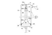
- FIG. 1 is a longitudinal cross-sectional view of a compressed air storage container of the present invention.
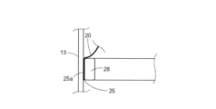
- FIG. 2 is a partially enlarged sectional view of FIG. 1.
- 1 is a flow diagram of a power generation device including a compressed air storage device of the present invention.
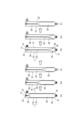
- FIG. 1 is an explanatory diagram of a method of using a compressed air storage device including a compressed air storage container of the present invention.
- the compressed air storage container 1 includes a cylindrical container 10 (hereinafter simply referred to as "cylindrical container 10") with both ends closed, and a cylindrical isolation membrane 20 disposed inside the cylindrical container 10. .
- a cylindrical container 10 hereinafter simply referred to as "cylindrical container 10"
- a cylindrical isolation membrane 20 disposed inside the cylindrical container 10.
- the inner space 30 of the cylindrical isolation membrane 20 is a buffer gas supply space
- the outer space 35 of the cylindrical isolation membrane 20 is a compressed air supply space (storage space).
- the cylindrical container 10 serves as a pressure accumulating container, and is preferably made of pressure-resistant metal such as carbon steel or stainless steel.
- the cross-sectional shape of the cylindrical container 10 is preferably circular, but it can also be formed into a desired shape such as an ellipse or a polygon depending on conditions such as the installation location.
- the dimensions of the cylindrical container 10 can be appropriately set depending on conditions such as the required amount of compressed air to be stored and the installation location. For example, if the cross-sectional shape in the width direction is circular, a diameter of 0.8 to 2.0 m and a height of 20 to 40 m can be used; Smaller ranges can also be used.
- the cylindrical container 10 is installed vertically, and includes a cylindrical side surface 13 , a ceiling surface 11 that closes the upper end opening of the cylindrical side surface 13 , and a lower end opening of the cylindrical side surface 13 . It has a bottom part 12 that closes the bottom part 12.
- a compressed air supply port and a discharge port 14 are provided near the upper end of the ceiling surface portion 11 or the side surface portion 13, and are connected to a line 41 for supplying and discharging compressed air.
- the compressed air supply port and the compressed air discharge port are one, but the compressed air supply port and the compressed air discharge port may be independent and separate.
- the bottom portion 12 has a buffer gas discharge port and a supply port 16, and is connected to a line 42 for supplying and discharging the buffer gas.
- there is one buffer gas supply port and one discharge port but the buffer gas supply port and the compressed air discharge port may be independent and separate ports.
- the cylindrical isolation membrane 20 is suspended from the ceiling part 11 in a state where the first end opening 21 side located on the ceiling part 11 side of the cylindrical container 10 is grouped together and sealed.
- the method of sealing the first end opening 21 side of the cylindrical isolation membrane 20 is not particularly limited, and for example, the first end opening 21 side of the cylindrical isolation membrane 20 may be tied together with a cable tie.
- FIG. 1 the first end opening 21 side of the cylindrical isolation membrane 20 is pushed together into the cap 22, and then an adhesive is poured into the cap 22 to seal it.
- the cylindrical isolation membrane 20 is suspended from the ceiling surface 11 of the cylindrical container 10 by a spring hanger 23.
- the spring hanger 23 has a first end 23 a fixed to the ceiling surface 11 and a second end 23 b fixed to the first end opening 21 (cap 22 ) of the cylindrical isolation membrane 20 .
- the compressed air storage container 1 When the compressed air storage container 1 is used as a compressed air storage device 50 including the compressed air storage container 1, (i) inside the cylindrical isolation membrane 20 is used as a means for measuring the amount of air stored in the compressed air storage container 1. a flow meter for measuring the change in the flow rate of the buffer gas discharged from the space 30 or supplied to the inner space 30; (ii) compressed air supplied to or discharged from the outer space 35 of the cylindrical isolation membrane 20; (iii) a weight meter such as a load cell for measuring changes in the hanging load applied to the spring hanger 23 suspending the cylindrical isolation membrane 20; (iv) a cylindrical A measuring means (including a combination thereof) selected from a displacement meter such as a level meter for measuring changes in the amount of spring extension of the spring hanger 23 suspending the isolation membrane 20 can be used.
- the compressed air storage container 1 has a spring hanger 23 that suspends the cylindrical isolation membrane 20 from the ceiling surface part 11, and is equipped with a device that can measure the hanging load of the cylindrical isolation membrane
- the cylindrical isolation membrane 20 has a second end opening 25 located on the bottom 12 side of the cylindrical container 10 facing the bottom 12, and a peripheral edge 25a of the second end opening 25 facing the bottom 12 and the side surface. It is fixed in close contact with the vicinity of the connection part 13 (in FIGS. 1 and 2, it is fixed on the side surface part 13 side).
- the diameter and length of the cylindrical isolation membrane 20 are adjusted according to the size of the cylindrical container 10. Desirably, it is about ⁇ 10% of the inner diameter of the container 10.
- the cylindrical isolation membrane 20 has no air permeability, and when suspended from the ceiling surface 11 of the cylindrical container 10 with the first end opening 21 side closed together, the second end opening 25
- the peripheral edge 25a of the cylindrical container 10 can be maintained in a skirt-like state in contact with the bottom 12 or the side surface 13 in the vicinity of the bottom 12 by its own weight. It is something that is closely followed.
- Such a cylindrical isolation membrane 20 can have a mass per unit area of 500 g/m 2 or more, and can be made of a material selected from a membrane made of synthetic resin, rubberized cloth, and a combination thereof. is preferred.
- Rubberized cloth is a sheet made by laminating rubber to cloth, and is a composite material that has both the characteristics of cloth and rubber. Examples include a composite sheet manufactured by laminating rubber rolled with a calendar roll on one or both sides of fibers of a woven or nonwoven fabric, and a composite sheet manufactured by sandwiching rubber between fibers.
- the method of fixing the second opening 25 side of the cylindrical isolation membrane 20 is such that the smooth movement of the cylindrical isolation membrane 20 is not obstructed or the cylindrical isolation membrane 20 is not damaged due to contact with fixing tools.
- the peripheral edge 25a of the second end opening 25 of the cylindrical isolation membrane 20 is in close contact with the vicinity of the connection between the bottom surface 12 and the side surface 13 of the cylindrical container to maintain airtightness.
- the second end opening 25 may be fixed with the peripheral edge 25a of the second end opening 25 sandwiched between the side surface 13 and the ring-shaped fixture 28. It can be done.
- the ring-shaped fixture 28 may be a continuous ring-shaped fixture, or may be a fixture in which a plurality of divided fixtures are arranged in a ring-shape. That is, the peripheral edge 25a of the lower end side opening (second end opening 25) of the cylindrical isolation membrane 20 is connected to the bottom surface 10 of the hollow cylindrical container 10 using a continuous or discontinuous ring-shaped fixture 28. Alternatively, it is fixed in close contact with the side surface portion 13 near the bottom surface portion 12. As a specific fixing means, a plurality of fasteners such as bolts and nuts (not shown) (packing is also used as necessary) are used to secure the ring-shaped fixing member 28 and the inner surface of the side surface 13.
- a buffer gas outlet and supply port 16 are connected to an inner space 30 surrounded by the inner surface 20a of the cylindrical isolation membrane 20.
- a compressed air supply port and discharge port 14 are connected to an outer space 35 surrounded by the cylindrical container 10 and the outer surface 20b of the cylindrical isolation membrane 20. Since the inner space 30 and the outer space 35 are separated from each other with gas movement blocked by the cylindrical isolation membrane 20, the buffer gas does not move from the inner space 30 to the outer space 35, and the compressed air does not move from the outer space 35 to the inner space 30. Note that when the compressed air storage container 1 and the compressed air storage device 50 using the container are put into practical use, a small amount of gas movement is allowed to the extent that it does not affect normal operation.
- the supply port and the discharge port of the compressed air share one first opening 14, and the first opening 14 shares one line 41.
- one line 41 is branched into two, a first branch line 51 and a second branch line 53 via a three-way valve 55, the first branch line 51 becomes a compressed air supply line, and the second branch line 53 is a compressed air discharge line.
- a shutoff valve may be provided in both the first branch line 51 and the second branch line 53. If the compressed air supply port and the compressed air discharge port provided in the compressed air storage container 1 are independent and separate, the line 41 is not necessary and the line 51 is connected to the compressed air supply port.
- a line 53 is connected to the outlet.
- the supply port and the discharge port of the buffer gas share one second opening 16, and the second opening 16 shares one line 42 with the buffer gas discharge port.
- One line 42 is branched into two, a first branch line 66 and a second branch line 65, through a three-way valve 56, with the first branch line 66 becoming a buffer gas supply line and the second branch line 66 being a buffer gas supply line.
- 65 is a buffer gas discharge line.
- a shutoff valve may be provided in both the first branch line 66 and the second branch line 65. If the buffer gas supply port and the buffer gas discharge port provided in the compressed air storage container 1 are independent and separate, the line 42 is not necessary and the line 66 is connected to the buffer gas supply port.
- a line 65 is connected to the outlet of the.
- the compressed air storage device 50 (compressed air storage device)
- the compressed air storage device 50 (not including the power generating device 54) will be explained with reference to FIG.
- the embodiment of the compressed air storage device 50 shown in FIG. 3 includes a compressor 60, the compressor 60 is not essential, and an embodiment without the compressor 60 can also be provided. Furthermore, in embodiments that do not include the compressor 60, compression cooling is not performed and normal cooling is performed.
- the compressed air storage device 50 includes the above-described compressed air storage container 1, and the number of compressed air storage containers 1 may be one or multiple (for example, 50 to 100) connected in parallel. .
- a compressed air discharge/supply port 14 on the ceiling surface portion 11 side is connected to a compressed air supply line 51 and a compressed air discharge line 53 via a three-way valve 55.
- the compressed air supply line 51 is connected to a compressed air supply device 52.
- the compressed air supply device 52 is a compressor (not limited to a single compressor but also includes a combination of multiple machines such as a low pressure compressor and a high pressure compressor), hot water called TES (Thermal Energy Storage), liquid state such as thermal oil, etc. These include heat storage devices, heat exchangers, etc., which include heat carriers such as solid media such as media, ceramics, pebbles, and bricks.
- the compressed air discharge line 53 is connected to an object 54 for compressed air energy.
- the compressed air energy usage target 54 is, for example, a turbine generator.
- the cylindrical container 10 of the compressed air storage container 1 has a buffer gas discharge port 16 on the bottom portion 12 side connected to a buffer gas discharge line 65, a buffer gas compressor 60, A buffer gas discharge line 65, a heat exchanger 61 for cooling and heating the buffer gas, a buffer gas discharge line 65, and a storage container 62 for compressed and cooled liquefied buffer gas are connected in this order.
- the storage container 62 for the liquefied buffer gas after compression cooling includes a buffer gas supply line 66 , a heat exchanger 61 for cooling and heating the buffer gas, a buffer gas supply line 66 , a three-way valve 56 , and a compressed air storage container 1 . It is connected to a buffer gas supply port 16 on the bottom portion 12 side of the cylindrical container 10 .
- the compressed air storage container 1 When used as a compressed air storage device, the compressed air storage container 1 can be installed above ground, partially underground and the rest above ground, or completely underground. It is preferable to install it in one of the following forms, and among these installation forms, a form in which it is installed above ground and a form in which it is partially installed underground are more preferable. When using a large number of compressed air storage containers 1 (for example, 100), they may be installed above ground, some may be partially installed underground, or other installation forms may be mixed as necessary. .
- FIG. 4(a) A method of using the compressed air storage device 50 of the present invention will be explained with reference to FIGS. 3 and 4.
- FIG. 4(a) A method of using the compressed air storage device 50 is a method of storing compressed air using the compressed air storage device 50 and a method of using compressed air.
- Procedure (operation) 1 will be explained with reference to FIG. 4(a).
- step 1 when storing compressed air in the compressed air storage container 1, the compressed air is stored in the inner space 30 in the compressed air storage container 1 filled with buffer gas (preferably carbon dioxide gas)
- buffer gas preferably carbon dioxide gas
- the internal space 30 is filled with buffer gas (carbon dioxide gas) to the maximum extent, so the spring hanger 23 is in its most contracted state, and the load on the spring hanger 23 is at its minimum. It becomes.
- the load at this time is preferably 20% or less of the weight of the cylindrical isolation membrane 20, more preferably 15% or less, and even more preferably 10% or less.
- Step (operation) 2 will be explained with reference to FIGS. 4(b) and 4(c).
- step (operation) 2 first, supply of compressed air into the outer space 35 is started (FIG. 4(b)). Thereafter, when the pressure inside the compressed air storage container 1 rises to a predetermined value, while continuing to supply compressed air into the outside space 35, the buffer gas is supplied from the inside space 30 through the buffer gas outlet 16, the line 42, and the buffer gas. The buffer gas is discharged from the gas discharge line 65 (FIG. 4(c)). The discharged buffer gas passes through a buffer gas compressor 60 and a heat exchanger 61 that cools and heats the buffer gas, and is stored in a storage container 62 as a liquefied buffer gas. As shown in FIGS. 4(b) and 4(c), the volume of the inner space 30 decreases as the buffer gas is discharged, while the volume of the outer space 35 to which compressed air is supplied increases.
- Step (operation) 3 will be explained with reference to FIG. 4(d).
- step (operation) 3 the amount of compressed air supplied into the outer space 35 has reached a predetermined amount, so the supply of compressed air into the outer space 35 is stopped, and the buffer gas is discharged from the inner space 30. stop.
- the change in the hanging load applied to the spring hanger 23 is measured, and the stop timing is determined based on the change in the load.
- the external space 35 is filled with air to the maximum extent, so the spring hanger 23 is in its most extended state, and the hanging load applied to the spring hanger 23 is at its maximum. There is.
- the load at this time is preferably 80% or more, more preferably 85% or more, and even more preferably 90% or more of the weight of the cylindrical isolation membrane 20.
- the stop timing can be determined from the amount of expansion and contraction of the spring of the spring hanger 23, and a flow meter is attached to the compressed air supply/discharge line 41 or the buffer gas supply/discharge line 42.
- the stop timing may be set to the time when the amount of compressed air (time integral of compressed air flow rate (kg/sec)) or the amount of discharged buffer gas (time integral of buffer gas flow rate (kg/sec)) reaches a predetermined value. can.
- Steps (operations) 4 and 5 will be explained with reference to FIGS. 4(e) and 4(f).
- the compressed air is discharged while the outer space 35 of the cylindrical isolation membrane 20 in the compressed air storage container 1 is filled with compressed air (FIG. 4(d)).
- Compressed air is discharged from line 53 and supplied to an object of use (eg, a turbine generator) 54 .
- Compressed air is discharged from the outer space 35 of the cylindrical isolation membrane 20 (FIG. 4(e)), and when the pressure inside the compressed air storage container 1 drops to a predetermined value, the supply of compressed air to the target 54 is stopped.
- a buffer gas is supplied into the inner space 30 of the cylindrical isolation membrane 20 (FIG.
- the buffer gas supplied into the inner space 30 of the cylindrical isolation membrane 20 at this time is the liquefied buffer gas stored in the storage container 62, which is vaporized by the heat exchanger 61 that cools and heats the buffer gas. It is something.
- Step (operation) 6 will be explained with reference to FIG. 4(a). Since the amount of compressed air discharged from the outer space 35 in the compressed air storage container 1 to the target 54 has reached a predetermined amount, the supply of buffer gas to the inner space 30 of the cylindrical isolation membrane 20 is stopped, and the cylindrical When stopping the discharge of compressed air in the outer space 35 of the isolation membrane 20, the change in the hanging load applied to the spring hanger 23 is measured, and the stop timing is determined based on the change in load.
- the stop timing can be determined from the amount of expansion and contraction of the spring of the spring hanger 23, and a flow meter is attached to the compressed air supply/discharge line 41 or the buffer gas supply/discharge line 42,
- the stop timing may be set to the time when the amount of compressed air (time integral of compressed air flow rate (kg/sec)) or the supplied buffer gas amount (time integral of buffer gas flow rate (kg/sec)) reaches a predetermined value. can.
- the supply and discharge of buffer gas to the inner space 30 and the discharge and supply of compressed air to the outer space 35 are performed in a mutually related manner.
- storing air it is possible to store air in a capacity close to the internal volume of the cylindrical container 10, and when using compressed air, almost the entire amount of the stored compressed air can be discharged while maintaining the pressure at a high level. Therefore, the amount of compressed air that can be used per volume of the compressed air storage container can be almost doubled compared to a conventional simple compressed air storage container (a simple container that does not utilize an isolation membrane or a buffer gas). This means that the size and number of compressed air storage vessels can be significantly reduced compared to the use of conventional simple compressed air storage vessels.
- the power generation device of the present invention includes the above-described compressed air storage device 50 and a power generation device 54 including a turbine generator.
- the power generation method of the present invention is a method of generating power by supplying compressed air stored in the compressed air storage device 50 to the turbine generator of the power generation device 54 and rotating the turbine.
- the power generation method of the present invention can also continuously generate power by continuously repeating steps 1 to 6 described above, but it can be carried out as in the following embodiments (a), (b), or (c). It is preferable.
- (a) A method of generating electricity by storing compressed air during the day using surplus power generated by solar power generation, and supplying the compressed air stored in the compressed air storage device to a turbine generator at night. .
- (b) A method of generating electricity by storing compressed air at night using nighttime electricity and supplying the compressed air stored in the compressed air storage device to a turbine generator during the day.
- (c) Store compressed air when excess power is generated from renewable energy power generation (excluding solar power generation) that fluctuates every few hours, and store the compressed air in the compressed air storage device when the amount of power generation decreases. Any power generation method selected from power generation methods that alleviate fluctuations in power generation by supplying stored compressed air to a turbine generator.
- the power generation using renewable energy that fluctuates in units of several hours in the method (c) is, for example, wind power generation that fluctuates depending on the weather.
- the compressed air storage container 1 (compressed air storage device 50) shown in FIG. 1 was used to store and discharge compressed air (FIGS. 3 and 4(a) to (f)).
- compressed air storage container 1 a cylindrical container made of carbon steel with a diameter of 2 m and a height of 20 m was used for the test.
- the cylindrical separation membrane 20 used had dimensions similar to the internal dimensions of the cylindrical container 10.
- step 1 while the inner space 30 in the compressed air storage container 10 is filled with buffer gas (carbon dioxide gas), the compressed air supply line 51 and the compressed air supply port 14 are The supply of compressed air into the outer space 35 in the compressed air storage container 1 was started.
- buffer gas carbon dioxide gas
- step 2 while continuing to supply compressed air into the outer space 35, the buffer gas is supplied from the inner space 30 through the buffer gas outlet 16 and the buffer gas discharge line 65.
- the gas was discharged, cooled and liquefied, and then stored in the storage tank 62.
- the volume of the inner space 30 is reduced because the buffer gas is discharged, and the volume of the outer space 35 is increased because compressed air is supplied.
- step 3 when the supply of compressed air into the outer space 35 is stopped and the discharge of buffer gas from the inner space 30 is stopped, the load applied to the cylindrical isolation membrane 20 is The change was measured, and the stop timing (time to stop the supply of compressed air) was determined based on the change in the load.
- the stop timing was set when the load applied to the spring hanger 23 reached 85 to 95% of the weight of the cylindrical isolation membrane 10. Further, the volume of the external space 35 in FIG. 4(d) was approximately 90% of the internal volume of the cylindrical container 10.
- steps 4 and 5 when the compressed air is discharged and used, the outer space 35 of the cylindrical isolation membrane 10 in the compressed air storage container 1 is filled with compressed air.
- compressed air was discharged from the compressed air discharge line 53 and supplied to the target (turbine generator) 54.
- the target turbine generator
- the compressed air is discharged from the outer space 35 of the cylindrical isolation membrane 20 and the buffer gas stored in the buffer gas storage container 62 is heated and vaporized while continuing to be supplied to the target 54. Then, it was supplied into the inner space 30 of the cylindrical isolation membrane 20.
- step 6 the supply of buffer gas into the inner space 30 of the cylindrical isolation membrane 20 is stopped, and the compressed air in the outer space 35 of the cylindrical isolation membrane 20 is discharged and sent to the target of use.
- the change in the load applied to the cylindrical isolation membrane 20 was measured, and the stop timing (time to stop the supply of buffer gas) was determined based on the change in load.
- the load applied to the cylindrical isolation membrane 20 varies in relation to the amount of air stored in the compressed air storage vessel 1. Changes in the amount of air stored in the compressed air storage container 1 in Steps 3 and 6 are determined by the amount of discharge (time integral value of flow rate) of the first gas from outside space 35 or the second gas from inside space 30.
- the compressed air storage container of the present invention can significantly reduce the power generation cost of a power generation method that stores and utilizes compressed air energy by creating a compressed air storage device that includes the same. This will make it possible to generate electricity using compressed air energy storage technology at a realistic cost, even in regions like Japan where there is almost no underground space where large amounts of compressed air can be stored.
- Compressed air storage container 10 Cylindrical container 20 Cylindrical isolation membrane 23 Spring hanger 30 Inner space 35 Outer space 50 Compressed air storage device 52 Compressed air supply device 54 Power generation device 60 Buffer gas compressor 61 Cooling/heating of buffer gas 62 Storage container for liquefied buffer gas after compression cooling
Landscapes
- Engineering & Computer Science (AREA)
- Mechanical Engineering (AREA)
- General Engineering & Computer Science (AREA)
- Chemical & Material Sciences (AREA)
- Combustion & Propulsion (AREA)
- Filling Or Discharging Of Gas Storage Vessels (AREA)
- Power Engineering (AREA)
- Life Sciences & Earth Sciences (AREA)
- Sustainable Development (AREA)
- Sustainable Energy (AREA)
Priority Applications (5)
| Application Number | Priority Date | Filing Date | Title |
|---|---|---|---|
| KR1020257003104A KR20250047994A (ko) | 2022-08-01 | 2023-07-20 | 압축공기 저장 용기와 상기 압축공기 저장 용기를 포함하는 압축공기 저장 장치 |
| US18/993,748 US20260009374A1 (en) | 2022-08-01 | 2023-07-20 | Compressed air storage container and compressed air storage apparatus comprising the compressed air storage container |
| JP2024538922A JPWO2024029353A1 (https=) | 2022-08-01 | 2023-07-20 | |
| CN202380057343.9A CN119630919A (zh) | 2022-08-01 | 2023-07-20 | 压缩空气储藏容器和包括前述压缩空气储藏容器的压缩空气储藏装置 |
| EP23849908.1A EP4567319A1 (en) | 2022-08-01 | 2023-07-20 | Compressed air storage container, and compressed air storage device including said compressed air storage container |
Applications Claiming Priority (2)
| Application Number | Priority Date | Filing Date | Title |
|---|---|---|---|
| JP2022-122615 | 2022-08-01 | ||
| JP2022122615 | 2022-08-01 |
Publications (1)
| Publication Number | Publication Date |
|---|---|
| WO2024029353A1 true WO2024029353A1 (ja) | 2024-02-08 |
Family
ID=89848833
Family Applications (1)
| Application Number | Title | Priority Date | Filing Date |
|---|---|---|---|
| PCT/JP2023/026557 Ceased WO2024029353A1 (ja) | 2022-08-01 | 2023-07-20 | 圧縮空気貯蔵容器と前記圧縮空気貯蔵容器を含む圧縮空気貯蔵装置 |
Country Status (7)
| Country | Link |
|---|---|
| US (1) | US20260009374A1 (https=) |
| EP (1) | EP4567319A1 (https=) |
| JP (1) | JPWO2024029353A1 (https=) |
| KR (1) | KR20250047994A (https=) |
| CN (1) | CN119630919A (https=) |
| TW (1) | TW202413787A (https=) |
| WO (1) | WO2024029353A1 (https=) |
Citations (7)
| Publication number | Priority date | Publication date | Assignee | Title |
|---|---|---|---|---|
| JPS5238607U (https=) * | 1975-09-11 | 1977-03-18 | ||
| JP2003148688A (ja) * | 2001-11-13 | 2003-05-21 | Hitachi Constr Mach Co Ltd | 圧縮天然ガス供給装置と圧縮天然ガス供給システムと圧縮天然ガス供給方法 |
| WO2007096656A1 (en) | 2006-02-27 | 2007-08-30 | Highview Enterprises Limited | A method of storing energy and a cryogenic energy storage system |
| JP2009538223A (ja) * | 2006-05-25 | 2009-11-05 | エア プロダクツ アンド ケミカルズ インコーポレイテッド | 流体貯蔵及び分給システム |
| WO2009146101A2 (en) | 2008-04-02 | 2009-12-03 | The Regents Of The University Of California | Carbon dioxide (co2) as cushion gas for compressed air energy storage (caes) |
| US8801332B2 (en) * | 2010-02-15 | 2014-08-12 | Arothron Ltd. | Underwater energy storage system and power station powered therewith |
| EP3255266B1 (en) | 2016-06-07 | 2018-12-12 | Dresser Rand Company | Hybrid compressed air energy storage system and process |
Family Cites Families (45)
| Publication number | Priority date | Publication date | Assignee | Title |
|---|---|---|---|---|
| US569028A (en) * | 1896-10-06 | Leopold nathan | ||
| US1673696A (en) * | 1926-02-24 | 1928-06-12 | Republic Steel Package Company | Dispensing tank |
| US1763950A (en) * | 1929-08-20 | 1930-06-17 | Brill Clinton Morgan | Gasoline storage tank |
| US2758747A (en) * | 1949-12-10 | 1956-08-14 | Standard Oil Co | Multiple compartment tank |
| US2600458A (en) * | 1950-03-25 | 1952-06-17 | Harry A Ackley | Upflow pressure diatomite filtering apparatus |
| FR1462315A (fr) * | 1965-10-12 | 1966-04-15 | Olaer Patent Co | Bloc plongeur pour réservoirs de pression et ses applications |
| US3493496A (en) * | 1968-05-13 | 1970-02-03 | Desalination Systems | Purified water supply apparatus and method |
| US3720230A (en) * | 1971-04-14 | 1973-03-13 | Coronet Mfg Co Inc | Apparatus for admixing liquids in predetermined ratio |
| US3974847A (en) * | 1971-08-05 | 1976-08-17 | Hodges Kenneth M | Liquid additive dispenser |
| US4047645A (en) * | 1976-06-08 | 1977-09-13 | Caliendo Joseph L | Aerosol device with telescoping container parts |
| GB2176589A (en) * | 1985-06-01 | 1986-12-31 | Warmac Ltd | Expansion tank |
| US4635848A (en) * | 1985-11-06 | 1987-01-13 | Little Charles F | Irrigation additive delivery system |
| US4902304A (en) * | 1986-05-07 | 1990-02-20 | Envirex Inc. | Separate low pressure gas storage system |
| US5255722A (en) * | 1992-03-12 | 1993-10-26 | Envirex Inc. | Vaporless liquid containment system |
| US5499750A (en) * | 1995-01-17 | 1996-03-19 | Manifold; William J. | Spraying device having a removable and replaceable bladder |
| US6093312A (en) * | 1998-01-22 | 2000-07-25 | Entre Pure, Inc. | Ice dispenser with an air-cooled bin |
| DE19813970A1 (de) * | 1998-03-20 | 1999-09-30 | Otto Heat Heizungs | Kombiniertes Brauch- und Heizungswasserausdehnungsgefäß |
| US6619930B2 (en) * | 2001-01-11 | 2003-09-16 | Mandus Group, Ltd. | Method and apparatus for pressurizing gas |
| US6925868B2 (en) * | 2001-06-22 | 2005-08-09 | Young Manufacturing & Engineering, Inc. | Acoustic volume indicator |
| US7216536B2 (en) * | 2001-06-22 | 2007-05-15 | Young Manufacturing & Engineering, Inc. | Acoustic volume indicator |
| US6786364B2 (en) * | 2001-08-08 | 2004-09-07 | Mcbride Dale | Transportable storage with an autonomous dispensing system |
| DE102006004121A1 (de) * | 2006-01-25 | 2007-07-26 | Hydac Technology Gmbh | Druckbehälter |
| US20080035647A1 (en) * | 2006-08-08 | 2008-02-14 | James Fuller | Expansion tank with a predictive sensor |
| US20090142636A1 (en) * | 2007-11-30 | 2009-06-04 | Kiyoshi Handa | Carbon Fiber Warming System for Fiber Composite Gas Storage Cylinders |
| US8047009B2 (en) * | 2008-12-09 | 2011-11-01 | Tire Seal, Inc. | Method and apparatus for providing additive fluids to refrigerant circuit |
| WO2012171832A1 (de) * | 2011-06-16 | 2012-12-20 | Reinhardt, Gaby Traute | Druck-speichereinrichtung |
| DE102011082726A1 (de) * | 2011-09-15 | 2013-03-21 | Gaby Traute Reinhardt | Druck-Speichereinrichtung |
| DE102011107883A1 (de) * | 2011-07-18 | 2013-01-24 | Gaby Traute Reinhardt | Druck-Speichereinrichtung |
| DE102011086894A1 (de) * | 2011-11-22 | 2013-05-23 | Gaby Traute Reinhardt | Druck-Speichereinrichtung |
| US9188284B2 (en) * | 2012-02-29 | 2015-11-17 | Luon Energy Llc | Natural gas adsorption devices |
| EP3447357A1 (en) * | 2015-05-26 | 2019-02-27 | Nissan Motor Co., Ltd. | High-pressure gas container |
| CN206890071U (zh) * | 2016-05-08 | 2018-01-16 | 施特劳斯净水有限公司 | 加压气体容器及多件式组合件 |
| KR101731960B1 (ko) * | 2016-07-21 | 2017-05-04 | (주)동희산업 | 차량용 고압용기 |
| UA129085C2 (uk) * | 2018-10-24 | 2025-01-08 | Емтрол Лайсенсінг, Інк. | Напірна ємність з пластиковим вкладишем |
| US11559964B2 (en) * | 2019-06-06 | 2023-01-24 | Northrop Grumman Systems Corporation | Composite structures, composite storage tanks, vehicles including such composite storage tanks, and related systems and methods |
| DE202020106328U1 (de) * | 2019-11-08 | 2021-02-10 | Additive Space Gmbh | Behälter |
| JP7701171B2 (ja) * | 2021-03-29 | 2025-07-01 | 本田技研工業株式会社 | 高圧ガスタンク |
| JP7555306B2 (ja) * | 2021-06-08 | 2024-09-24 | 本田技研工業株式会社 | 高圧タンク、及び、その製造方法 |
| JP2024525420A (ja) * | 2021-06-23 | 2024-07-12 | バイオミスト,インコーポレイテッド | 窒素発生及び殺菌システム |
| US12338951B2 (en) * | 2021-07-13 | 2025-06-24 | Altenloh, Brinck & Co. U.S., Inc. | Pressurized adhesive tank system |
| JP7651992B2 (ja) * | 2021-07-13 | 2025-03-27 | トヨタ自動車株式会社 | 高圧タンクユニット |
| JP7420774B2 (ja) * | 2021-08-30 | 2024-01-23 | 株式会社豊田中央研究所 | 高圧タンク |
| NO20220270A1 (en) * | 2022-03-03 | 2023-09-04 | Lattice Int As | Membrane tank feasible for cryogenic service |
| EP4296558A1 (en) * | 2022-06-23 | 2023-12-27 | L'air Liquide, Societe Anonyme Pour L'etude Et L'exploitation Des Procedes Georges Claude | Method for producing a composite cylindrical tank and composite tank produced by this method |
| DE102022210662A1 (de) * | 2022-10-10 | 2024-04-11 | Hyundai Motor Company | Wasserstofftank und Verfahren zum Betreiben eines Wasserstofftanks |
-
2023
- 2023-07-20 JP JP2024538922A patent/JPWO2024029353A1/ja active Pending
- 2023-07-20 WO PCT/JP2023/026557 patent/WO2024029353A1/ja not_active Ceased
- 2023-07-20 CN CN202380057343.9A patent/CN119630919A/zh active Pending
- 2023-07-20 TW TW112127121A patent/TW202413787A/zh unknown
- 2023-07-20 EP EP23849908.1A patent/EP4567319A1/en active Pending
- 2023-07-20 US US18/993,748 patent/US20260009374A1/en active Pending
- 2023-07-20 KR KR1020257003104A patent/KR20250047994A/ko active Pending
Patent Citations (7)
| Publication number | Priority date | Publication date | Assignee | Title |
|---|---|---|---|---|
| JPS5238607U (https=) * | 1975-09-11 | 1977-03-18 | ||
| JP2003148688A (ja) * | 2001-11-13 | 2003-05-21 | Hitachi Constr Mach Co Ltd | 圧縮天然ガス供給装置と圧縮天然ガス供給システムと圧縮天然ガス供給方法 |
| WO2007096656A1 (en) | 2006-02-27 | 2007-08-30 | Highview Enterprises Limited | A method of storing energy and a cryogenic energy storage system |
| JP2009538223A (ja) * | 2006-05-25 | 2009-11-05 | エア プロダクツ アンド ケミカルズ インコーポレイテッド | 流体貯蔵及び分給システム |
| WO2009146101A2 (en) | 2008-04-02 | 2009-12-03 | The Regents Of The University Of California | Carbon dioxide (co2) as cushion gas for compressed air energy storage (caes) |
| US8801332B2 (en) * | 2010-02-15 | 2014-08-12 | Arothron Ltd. | Underwater energy storage system and power station powered therewith |
| EP3255266B1 (en) | 2016-06-07 | 2018-12-12 | Dresser Rand Company | Hybrid compressed air energy storage system and process |
Also Published As
| Publication number | Publication date |
|---|---|
| EP4567319A1 (en) | 2025-06-11 |
| KR20250047994A (ko) | 2025-04-07 |
| TW202413787A (zh) | 2024-04-01 |
| CN119630919A (zh) | 2025-03-14 |
| JPWO2024029353A1 (https=) | 2024-02-08 |
| US20260009374A1 (en) | 2026-01-08 |
Similar Documents
| Publication | Publication Date | Title |
|---|---|---|
| US11767950B2 (en) | Hydrostatically compensated compressed gas energy storage system | |
| US6003460A (en) | Ship based gas transport system | |
| US12218499B2 (en) | Hydraulic compressed air energy storage system | |
| EP2043930A1 (en) | Thermal energy storage system | |
| RU2213255C1 (ru) | Способ преобразования, аккумулирования и использования ветровой энергии и комплекс для его осуществления | |
| RU2589811C2 (ru) | Судно для транспортировки сжатого газа | |
| CN114962976B (zh) | 一种通用压缩空气储能柔性储罐装置 | |
| CN104395684A (zh) | 蓄热器布置在过压区中的蓄压器电站 | |
| JP2024507117A (ja) | 燃料ガスによるエネルギー貯蔵システム | |
| US12607301B2 (en) | Combined high pressure receptacles | |
| US4174009A (en) | Long-period thermal storage accumulators | |
| CN108999770A (zh) | 一种海上非绝热等压双容器压缩空气储能系统及方法 | |
| WO2024029353A1 (ja) | 圧縮空気貯蔵容器と前記圧縮空気貯蔵容器を含む圧縮空気貯蔵装置 | |
| US12510060B2 (en) | Method for storing compressed air energy | |
| US12098888B2 (en) | Horizontal-axis heat recovery and storage system | |
| CN214535659U (zh) | 一种混凝土全容罐 | |
| WO2024253120A1 (ja) | 圧縮空気貯蔵容器と圧縮空気貯蔵容器を含む圧縮空気貯蔵装置 | |
| RU2781395C1 (ru) | Способ наземного адсорбционного хранения природного газа, метана и комплекс для его осуществления (варианты) | |
| KR20120126948A (ko) | 정압 가스 저장 시스템 및 이를 포함하는 압축 가스 저장 발전시스템 |
Legal Events
| Date | Code | Title | Description |
|---|---|---|---|
| 121 | Ep: the epo has been informed by wipo that ep was designated in this application |
Ref document number: 23849908 Country of ref document: EP Kind code of ref document: A1 |
|
| WWE | Wipo information: entry into national phase |
Ref document number: 2024538922 Country of ref document: JP |
|
| WWE | Wipo information: entry into national phase |
Ref document number: 18993748 Country of ref document: US |
|
| WWE | Wipo information: entry into national phase |
Ref document number: 2501000300 Country of ref document: TH |
|
| WWE | Wipo information: entry into national phase |
Ref document number: 202380057343.9 Country of ref document: CN |
|
| WWE | Wipo information: entry into national phase |
Ref document number: 202517007380 Country of ref document: IN |
|
| WWP | Wipo information: published in national office |
Ref document number: 202517007380 Country of ref document: IN |
|
| WWE | Wipo information: entry into national phase |
Ref document number: 2023849908 Country of ref document: EP |
|
| NENP | Non-entry into the national phase |
Ref country code: DE |
|
| ENP | Entry into the national phase |
Ref document number: 2023849908 Country of ref document: EP Effective date: 20250303 |
|
| WWP | Wipo information: published in national office |
Ref document number: 202380057343.9 Country of ref document: CN |
|
| WWP | Wipo information: published in national office |
Ref document number: 1020257003104 Country of ref document: KR |
|
| WWP | Wipo information: published in national office |
Ref document number: 2023849908 Country of ref document: EP |
|
| WWP | Wipo information: published in national office |
Ref document number: 18993748 Country of ref document: US |
|
| WWW | Wipo information: withdrawn in national office |
Ref document number: 2023849908 Country of ref document: EP |