WO2024029353A1 - Compressed air storage container, and compressed air storage device including said compressed air storage container - Google Patents
Compressed air storage container, and compressed air storage device including said compressed air storage container Download PDFInfo
- Publication number
- WO2024029353A1 WO2024029353A1 PCT/JP2023/026557 JP2023026557W WO2024029353A1 WO 2024029353 A1 WO2024029353 A1 WO 2024029353A1 JP 2023026557 W JP2023026557 W JP 2023026557W WO 2024029353 A1 WO2024029353 A1 WO 2024029353A1
- Authority
- WO
- WIPO (PCT)
- Prior art keywords
- compressed air
- cylindrical
- air storage
- buffer gas
- container
- Prior art date
Links
- 230000002093 peripheral effect Effects 0.000 claims abstract description 12
- 239000012528 membrane Substances 0.000 claims description 83
- 238000002955 isolation Methods 0.000 claims description 80
- 238000000034 method Methods 0.000 claims description 61
- 238000010248 power generation Methods 0.000 claims description 39
- 238000001816 cooling Methods 0.000 claims description 13
- 238000007599 discharging Methods 0.000 claims description 11
- 230000005611 electricity Effects 0.000 claims description 9
- 230000006835 compression Effects 0.000 claims description 6
- 238000007906 compression Methods 0.000 claims description 6
- 238000010438 heat treatment Methods 0.000 claims description 6
- 239000004744 fabric Substances 0.000 claims description 5
- 230000008602 contraction Effects 0.000 claims description 4
- 230000007423 decrease Effects 0.000 claims description 4
- 239000000463 material Substances 0.000 claims description 2
- 230000035699 permeability Effects 0.000 claims description 2
- 229920003002 synthetic resin Polymers 0.000 claims description 2
- 239000000057 synthetic resin Substances 0.000 claims description 2
- 230000008016 vaporization Effects 0.000 claims 1
- CURLTUGMZLYLDI-UHFFFAOYSA-N Carbon dioxide Chemical compound O=C=O CURLTUGMZLYLDI-UHFFFAOYSA-N 0.000 description 10
- 238000007789 sealing Methods 0.000 description 7
- 229910002092 carbon dioxide Inorganic materials 0.000 description 5
- 239000001569 carbon dioxide Substances 0.000 description 5
- 238000009434 installation Methods 0.000 description 4
- 239000002131 composite material Substances 0.000 description 3
- 238000004146 energy storage Methods 0.000 description 3
- 229910000975 Carbon steel Inorganic materials 0.000 description 2
- 239000000853 adhesive Substances 0.000 description 2
- 230000001070 adhesive effect Effects 0.000 description 2
- 239000010962 carbon steel Substances 0.000 description 2
- 238000010586 diagram Methods 0.000 description 2
- 238000005516 engineering process Methods 0.000 description 2
- 239000000835 fiber Substances 0.000 description 2
- 238000010030 laminating Methods 0.000 description 2
- FAPWRFPIFSIZLT-UHFFFAOYSA-M Sodium chloride Chemical compound [Na+].[Cl-] FAPWRFPIFSIZLT-UHFFFAOYSA-M 0.000 description 1
- 239000002390 adhesive tape Substances 0.000 description 1
- 230000015572 biosynthetic process Effects 0.000 description 1
- 239000011449 brick Substances 0.000 description 1
- 239000000969 carrier Substances 0.000 description 1
- 239000000919 ceramic Substances 0.000 description 1
- 238000006073 displacement reaction Methods 0.000 description 1
- 230000000694 effects Effects 0.000 description 1
- 238000005755 formation reaction Methods 0.000 description 1
- 238000005338 heat storage Methods 0.000 description 1
- 239000007788 liquid Substances 0.000 description 1
- 239000002184 metal Substances 0.000 description 1
- 238000005065 mining Methods 0.000 description 1
- 239000004745 nonwoven fabric Substances 0.000 description 1
- 238000012856 packing Methods 0.000 description 1
- -1 pebbles Substances 0.000 description 1
- 238000000926 separation method Methods 0.000 description 1
- 235000002639 sodium chloride Nutrition 0.000 description 1
- 239000011780 sodium chloride Substances 0.000 description 1
- 239000007787 solid Substances 0.000 description 1
- 239000010935 stainless steel Substances 0.000 description 1
- 229910001220 stainless steel Inorganic materials 0.000 description 1
- 239000000725 suspension Substances 0.000 description 1
- XLYOFNOQVPJJNP-UHFFFAOYSA-N water Substances O XLYOFNOQVPJJNP-UHFFFAOYSA-N 0.000 description 1
- 239000002759 woven fabric Substances 0.000 description 1
Images

Classifications
-
- F—MECHANICAL ENGINEERING; LIGHTING; HEATING; WEAPONS; BLASTING
- F02—COMBUSTION ENGINES; HOT-GAS OR COMBUSTION-PRODUCT ENGINE PLANTS
- F02C—GAS-TURBINE PLANTS; AIR INTAKES FOR JET-PROPULSION PLANTS; CONTROLLING FUEL SUPPLY IN AIR-BREATHING JET-PROPULSION PLANTS
- F02C6/00—Plural gas-turbine plants; Combinations of gas-turbine plants with other apparatus; Adaptations of gas- turbine plants for special use
- F02C6/14—Gas-turbine plants having means for storing energy, e.g. for meeting peak loads
- F02C6/16—Gas-turbine plants having means for storing energy, e.g. for meeting peak loads for storing compressed air
-
- F—MECHANICAL ENGINEERING; LIGHTING; HEATING; WEAPONS; BLASTING
- F17—STORING OR DISTRIBUTING GASES OR LIQUIDS
- F17C—VESSELS FOR CONTAINING OR STORING COMPRESSED, LIQUEFIED OR SOLIDIFIED GASES; FIXED-CAPACITY GAS-HOLDERS; FILLING VESSELS WITH, OR DISCHARGING FROM VESSELS, COMPRESSED, LIQUEFIED, OR SOLIDIFIED GASES
- F17C1/00—Pressure vessels, e.g. gas cylinder, gas tank, replaceable cartridge
-
- F—MECHANICAL ENGINEERING; LIGHTING; HEATING; WEAPONS; BLASTING
- F17—STORING OR DISTRIBUTING GASES OR LIQUIDS
- F17C—VESSELS FOR CONTAINING OR STORING COMPRESSED, LIQUEFIED OR SOLIDIFIED GASES; FIXED-CAPACITY GAS-HOLDERS; FILLING VESSELS WITH, OR DISCHARGING FROM VESSELS, COMPRESSED, LIQUEFIED, OR SOLIDIFIED GASES
- F17C13/00—Details of vessels or of the filling or discharging of vessels
Definitions
- the present invention relates to a compressed air storage container, a compressed air storage device including the compressed air storage container, a method of using compressed air, and a power generation device and power generation method using the compressed air storage device.
- CAES compressed air energy storage
- EP3255266B1 describes a hybrid CAES system of adiabatic CAES and non-adiabatic CAES in which heat generated during air storage is reused when air is discharged.
- WO 2009/146101A2 describes the use of carbon dioxide as a buffer gas in geological formations such as porous sandstone layers located at high depths, and by taking advantage of the fact that the volume of carbon dioxide that exceeds the critical pressure rapidly decreases, more air can be extracted. A method of storage is described.
- WO2007/096656A1 describes a technique for storing more air even in small-scale ground facilities by liquefying compressed air to reduce the storage volume.
- the present invention relates to a compressed air storage container that can reduce the volume of the container for storing compressed air, a compressed air storage device including the compressed air storage container, a method for using the compressed air storage device, and a power generation using the compressed air storage device.
- the objective is to provide equipment and a power generation method.
- the present invention includes a cylindrical container that is placed vertically and has both ends closed, and a cylindrical isolation membrane inside the cylindrical container that has both ends closed, and the cylindrical container that has both ends closed. , a cylindrical side surface portion, a ceiling surface portion that closes the upper end of the cylindrical side surface portion, and a bottom surface portion that closes the lower end of the cylindrical side surface portion;
- the cylindrical isolation membrane has an outlet and a second gas discharge/supply port on the bottom side, and the opening on the top end side of the cylindrical isolation membrane is bundled together and sealed. It is suspended from the ceiling surface of the cylindrical container, an opening on the lower end side is open opposite to the bottom surface, and a peripheral edge of the lower end opening of the cylindrical isolation membrane is suspended from the bottom surface or the bottom surface.
- the present invention provides a compressed air storage device including the above compressed air storage container, in which the first gas is compressed air and the second gas is a buffer gas, the cylindrical container
- the supply/discharge port on the ceiling side of the cylindrical container is connected to the compressed air supply/discharge line, and the discharge/supply port on the bottom side of the cylindrical container is connected to the buffer gas discharge/supply line and the buffer gas compression line.
- the first gas is the buffer gas and the second gas is compressed air
- the first gas is the buffer gas and the second gas is compressed air.
- the supply/discharge port on the bottom side of the cylindrical container is connected to a compressed air supply/discharge line
- the discharge/supply port on the ceiling side of the cylindrical container is connected to a buffer gas discharge/supply line.
- a compressed air storage device which is connected to a buffer gas compressor, a heat exchanger for cooling and heating the buffer gas, and a storage container for compressed and cooled liquefied buffer gas.
- the compressed air storage container is used in a compressed air storage device, the first gas is compressed air and the second gas is a buffer gas, or the first gas is a buffer gas and the second gas is The gas is compressed air.
- the present invention provides a method for using the compressed air storage device described above, in which compressed air is supplied to the outer space (or inner space) of the cylindrical isolation membrane in the compressed air storage container, and A process of discharging the buffer gas filled in the inner space (or outer space) of the cylindrical isolation membrane, and a process of supplying the buffer gas to the inner space (or outer space) and filling the outer space (or inner space).
- This is a method of use in which the steps of discharging compressed air are alternately carried out, and in the method of use, the outer space (or inner space) is used as a compressed air supply space, and the inner space (or outer space) is used as a buffer gas supply space.
- step 1 When storing compressed air, the inner space (or the outer space) is filled with buffer gas, and the compressed air supply line is connected to the outer space (or the inner space).
- step 1 of starting supply of compressed air to the outer space (or inner space), exhausting buffer gas from the inner space (or outer space) while continuing to supply compressed air to the outer space (or inner space);
- step 2 of cooling and storing the discharged buffer gas, stopping the supply of compressed air into the outer space (or inner space) and discharging the buffer gas from the inner space (or outer space).
- Step 3 when stopping, measuring the change in the air storage amount in the compressed air storage container and determining the stop timing based on the change in the air storage amount; when the compressed air is discharged and used, the outside space is Step 4: With the inside (or inside space) filled with compressed air, the compressed air is discharged from the compressed air discharge line and supplied to the target of use, from inside the outside space (or inside space).
- the buffer gas stored in the liquefied buffer gas storage container is heated and vaporized while discharging the compressed air and continuing supply to the target of use, and then supplied into the inner space (or outer space).
- Step 5 when stopping the supply of buffer gas into the inner space (or outer space), discharging compressed air in the outer space (or inner space), and stopping the supply to the target of use;
- a method for using a compressed air storage device comprising step 6 of measuring a change in the amount of air stored in the compressed air storage container and determining the stop timing based on the change in the amount of air stored.
- the present invention provides a power generation device and a power generation method having the above compressed air storage device and turbine generator.
- the compressed air storage device of the present invention includes a compressed air storage container that utilizes a buffer gas using a cylindrical isolation membrane, the amount of compressed air that can be stored is increased, and the amount of compressed air that can be used is also increased. I can do it.
- the compressed air storage container by pushing out the compressed air in the compressed air storage container with buffer gas through the cylindrical isolation membrane, it is possible to exhaust almost all of the compressed air in the compressed air storage container without reducing the exhaust pressure of the compressed air. can.
- the amount of electricity that can be recovered by the subsequent expander increases.
- the buffer gas and compressed air are always separated by the cylindrical isolation membrane, it is difficult for air to be mixed into the buffer gas, and there is almost no change in the purity of the buffer gas over time. As a result, the effects expected from the buffer gas are maintained stably over a long period of time.
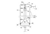
- FIG. 1 is a longitudinal cross-sectional view of a compressed air storage container of the present invention.
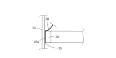
- FIG. 2 is a partially enlarged sectional view of FIG. 1.
- 1 is a flow diagram of a power generation device including a compressed air storage device of the present invention.
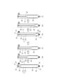
- FIG. 1 is an explanatory diagram of a method of using a compressed air storage device including a compressed air storage container of the present invention.
- the compressed air storage container 1 includes a cylindrical container 10 (hereinafter simply referred to as "cylindrical container 10") with both ends closed, and a cylindrical isolation membrane 20 disposed inside the cylindrical container 10. .
- a cylindrical container 10 hereinafter simply referred to as "cylindrical container 10"
- a cylindrical isolation membrane 20 disposed inside the cylindrical container 10.
- the inner space 30 of the cylindrical isolation membrane 20 is a buffer gas supply space
- the outer space 35 of the cylindrical isolation membrane 20 is a compressed air supply space (storage space).
- the cylindrical container 10 serves as a pressure accumulating container, and is preferably made of pressure-resistant metal such as carbon steel or stainless steel.
- the cross-sectional shape of the cylindrical container 10 is preferably circular, but it can also be formed into a desired shape such as an ellipse or a polygon depending on conditions such as the installation location.
- the dimensions of the cylindrical container 10 can be appropriately set depending on conditions such as the required amount of compressed air to be stored and the installation location. For example, if the cross-sectional shape in the width direction is circular, a diameter of 0.8 to 2.0 m and a height of 20 to 40 m can be used; Smaller ranges can also be used.
- the cylindrical container 10 is installed vertically, and includes a cylindrical side surface 13 , a ceiling surface 11 that closes the upper end opening of the cylindrical side surface 13 , and a lower end opening of the cylindrical side surface 13 . It has a bottom part 12 that closes the bottom part 12.
- a compressed air supply port and a discharge port 14 are provided near the upper end of the ceiling surface portion 11 or the side surface portion 13, and are connected to a line 41 for supplying and discharging compressed air.
- the compressed air supply port and the compressed air discharge port are one, but the compressed air supply port and the compressed air discharge port may be independent and separate.
- the bottom portion 12 has a buffer gas discharge port and a supply port 16, and is connected to a line 42 for supplying and discharging the buffer gas.
- there is one buffer gas supply port and one discharge port but the buffer gas supply port and the compressed air discharge port may be independent and separate ports.
- the cylindrical isolation membrane 20 is suspended from the ceiling part 11 in a state where the first end opening 21 side located on the ceiling part 11 side of the cylindrical container 10 is grouped together and sealed.
- the method of sealing the first end opening 21 side of the cylindrical isolation membrane 20 is not particularly limited, and for example, the first end opening 21 side of the cylindrical isolation membrane 20 may be tied together with a cable tie.
- FIG. 1 the first end opening 21 side of the cylindrical isolation membrane 20 is pushed together into the cap 22, and then an adhesive is poured into the cap 22 to seal it.
- the cylindrical isolation membrane 20 is suspended from the ceiling surface 11 of the cylindrical container 10 by a spring hanger 23.
- the spring hanger 23 has a first end 23 a fixed to the ceiling surface 11 and a second end 23 b fixed to the first end opening 21 (cap 22 ) of the cylindrical isolation membrane 20 .
- the compressed air storage container 1 When the compressed air storage container 1 is used as a compressed air storage device 50 including the compressed air storage container 1, (i) inside the cylindrical isolation membrane 20 is used as a means for measuring the amount of air stored in the compressed air storage container 1. a flow meter for measuring the change in the flow rate of the buffer gas discharged from the space 30 or supplied to the inner space 30; (ii) compressed air supplied to or discharged from the outer space 35 of the cylindrical isolation membrane 20; (iii) a weight meter such as a load cell for measuring changes in the hanging load applied to the spring hanger 23 suspending the cylindrical isolation membrane 20; (iv) a cylindrical A measuring means (including a combination thereof) selected from a displacement meter such as a level meter for measuring changes in the amount of spring extension of the spring hanger 23 suspending the isolation membrane 20 can be used.
- the compressed air storage container 1 has a spring hanger 23 that suspends the cylindrical isolation membrane 20 from the ceiling surface part 11, and is equipped with a device that can measure the hanging load of the cylindrical isolation membrane
- the cylindrical isolation membrane 20 has a second end opening 25 located on the bottom 12 side of the cylindrical container 10 facing the bottom 12, and a peripheral edge 25a of the second end opening 25 facing the bottom 12 and the side surface. It is fixed in close contact with the vicinity of the connection part 13 (in FIGS. 1 and 2, it is fixed on the side surface part 13 side).
- the diameter and length of the cylindrical isolation membrane 20 are adjusted according to the size of the cylindrical container 10. Desirably, it is about ⁇ 10% of the inner diameter of the container 10.
- the cylindrical isolation membrane 20 has no air permeability, and when suspended from the ceiling surface 11 of the cylindrical container 10 with the first end opening 21 side closed together, the second end opening 25
- the peripheral edge 25a of the cylindrical container 10 can be maintained in a skirt-like state in contact with the bottom 12 or the side surface 13 in the vicinity of the bottom 12 by its own weight. It is something that is closely followed.
- Such a cylindrical isolation membrane 20 can have a mass per unit area of 500 g/m 2 or more, and can be made of a material selected from a membrane made of synthetic resin, rubberized cloth, and a combination thereof. is preferred.
- Rubberized cloth is a sheet made by laminating rubber to cloth, and is a composite material that has both the characteristics of cloth and rubber. Examples include a composite sheet manufactured by laminating rubber rolled with a calendar roll on one or both sides of fibers of a woven or nonwoven fabric, and a composite sheet manufactured by sandwiching rubber between fibers.
- the method of fixing the second opening 25 side of the cylindrical isolation membrane 20 is such that the smooth movement of the cylindrical isolation membrane 20 is not obstructed or the cylindrical isolation membrane 20 is not damaged due to contact with fixing tools.
- the peripheral edge 25a of the second end opening 25 of the cylindrical isolation membrane 20 is in close contact with the vicinity of the connection between the bottom surface 12 and the side surface 13 of the cylindrical container to maintain airtightness.
- the second end opening 25 may be fixed with the peripheral edge 25a of the second end opening 25 sandwiched between the side surface 13 and the ring-shaped fixture 28. It can be done.
- the ring-shaped fixture 28 may be a continuous ring-shaped fixture, or may be a fixture in which a plurality of divided fixtures are arranged in a ring-shape. That is, the peripheral edge 25a of the lower end side opening (second end opening 25) of the cylindrical isolation membrane 20 is connected to the bottom surface 10 of the hollow cylindrical container 10 using a continuous or discontinuous ring-shaped fixture 28. Alternatively, it is fixed in close contact with the side surface portion 13 near the bottom surface portion 12. As a specific fixing means, a plurality of fasteners such as bolts and nuts (not shown) (packing is also used as necessary) are used to secure the ring-shaped fixing member 28 and the inner surface of the side surface 13.
- a buffer gas outlet and supply port 16 are connected to an inner space 30 surrounded by the inner surface 20a of the cylindrical isolation membrane 20.
- a compressed air supply port and discharge port 14 are connected to an outer space 35 surrounded by the cylindrical container 10 and the outer surface 20b of the cylindrical isolation membrane 20. Since the inner space 30 and the outer space 35 are separated from each other with gas movement blocked by the cylindrical isolation membrane 20, the buffer gas does not move from the inner space 30 to the outer space 35, and the compressed air does not move from the outer space 35 to the inner space 30. Note that when the compressed air storage container 1 and the compressed air storage device 50 using the container are put into practical use, a small amount of gas movement is allowed to the extent that it does not affect normal operation.
- the supply port and the discharge port of the compressed air share one first opening 14, and the first opening 14 shares one line 41.
- one line 41 is branched into two, a first branch line 51 and a second branch line 53 via a three-way valve 55, the first branch line 51 becomes a compressed air supply line, and the second branch line 53 is a compressed air discharge line.
- a shutoff valve may be provided in both the first branch line 51 and the second branch line 53. If the compressed air supply port and the compressed air discharge port provided in the compressed air storage container 1 are independent and separate, the line 41 is not necessary and the line 51 is connected to the compressed air supply port.
- a line 53 is connected to the outlet.
- the supply port and the discharge port of the buffer gas share one second opening 16, and the second opening 16 shares one line 42 with the buffer gas discharge port.
- One line 42 is branched into two, a first branch line 66 and a second branch line 65, through a three-way valve 56, with the first branch line 66 becoming a buffer gas supply line and the second branch line 66 being a buffer gas supply line.
- 65 is a buffer gas discharge line.
- a shutoff valve may be provided in both the first branch line 66 and the second branch line 65. If the buffer gas supply port and the buffer gas discharge port provided in the compressed air storage container 1 are independent and separate, the line 42 is not necessary and the line 66 is connected to the buffer gas supply port.
- a line 65 is connected to the outlet of the.
- the compressed air storage device 50 (compressed air storage device)
- the compressed air storage device 50 (not including the power generating device 54) will be explained with reference to FIG.
- the embodiment of the compressed air storage device 50 shown in FIG. 3 includes a compressor 60, the compressor 60 is not essential, and an embodiment without the compressor 60 can also be provided. Furthermore, in embodiments that do not include the compressor 60, compression cooling is not performed and normal cooling is performed.
- the compressed air storage device 50 includes the above-described compressed air storage container 1, and the number of compressed air storage containers 1 may be one or multiple (for example, 50 to 100) connected in parallel. .
- a compressed air discharge/supply port 14 on the ceiling surface portion 11 side is connected to a compressed air supply line 51 and a compressed air discharge line 53 via a three-way valve 55.
- the compressed air supply line 51 is connected to a compressed air supply device 52.
- the compressed air supply device 52 is a compressor (not limited to a single compressor but also includes a combination of multiple machines such as a low pressure compressor and a high pressure compressor), hot water called TES (Thermal Energy Storage), liquid state such as thermal oil, etc. These include heat storage devices, heat exchangers, etc., which include heat carriers such as solid media such as media, ceramics, pebbles, and bricks.
- the compressed air discharge line 53 is connected to an object 54 for compressed air energy.
- the compressed air energy usage target 54 is, for example, a turbine generator.
- the cylindrical container 10 of the compressed air storage container 1 has a buffer gas discharge port 16 on the bottom portion 12 side connected to a buffer gas discharge line 65, a buffer gas compressor 60, A buffer gas discharge line 65, a heat exchanger 61 for cooling and heating the buffer gas, a buffer gas discharge line 65, and a storage container 62 for compressed and cooled liquefied buffer gas are connected in this order.
- the storage container 62 for the liquefied buffer gas after compression cooling includes a buffer gas supply line 66 , a heat exchanger 61 for cooling and heating the buffer gas, a buffer gas supply line 66 , a three-way valve 56 , and a compressed air storage container 1 . It is connected to a buffer gas supply port 16 on the bottom portion 12 side of the cylindrical container 10 .
- the compressed air storage container 1 When used as a compressed air storage device, the compressed air storage container 1 can be installed above ground, partially underground and the rest above ground, or completely underground. It is preferable to install it in one of the following forms, and among these installation forms, a form in which it is installed above ground and a form in which it is partially installed underground are more preferable. When using a large number of compressed air storage containers 1 (for example, 100), they may be installed above ground, some may be partially installed underground, or other installation forms may be mixed as necessary. .
- FIG. 4(a) A method of using the compressed air storage device 50 of the present invention will be explained with reference to FIGS. 3 and 4.
- FIG. 4(a) A method of using the compressed air storage device 50 is a method of storing compressed air using the compressed air storage device 50 and a method of using compressed air.
- Procedure (operation) 1 will be explained with reference to FIG. 4(a).
- step 1 when storing compressed air in the compressed air storage container 1, the compressed air is stored in the inner space 30 in the compressed air storage container 1 filled with buffer gas (preferably carbon dioxide gas)
- buffer gas preferably carbon dioxide gas
- the internal space 30 is filled with buffer gas (carbon dioxide gas) to the maximum extent, so the spring hanger 23 is in its most contracted state, and the load on the spring hanger 23 is at its minimum. It becomes.
- the load at this time is preferably 20% or less of the weight of the cylindrical isolation membrane 20, more preferably 15% or less, and even more preferably 10% or less.
- Step (operation) 2 will be explained with reference to FIGS. 4(b) and 4(c).
- step (operation) 2 first, supply of compressed air into the outer space 35 is started (FIG. 4(b)). Thereafter, when the pressure inside the compressed air storage container 1 rises to a predetermined value, while continuing to supply compressed air into the outside space 35, the buffer gas is supplied from the inside space 30 through the buffer gas outlet 16, the line 42, and the buffer gas. The buffer gas is discharged from the gas discharge line 65 (FIG. 4(c)). The discharged buffer gas passes through a buffer gas compressor 60 and a heat exchanger 61 that cools and heats the buffer gas, and is stored in a storage container 62 as a liquefied buffer gas. As shown in FIGS. 4(b) and 4(c), the volume of the inner space 30 decreases as the buffer gas is discharged, while the volume of the outer space 35 to which compressed air is supplied increases.
- Step (operation) 3 will be explained with reference to FIG. 4(d).
- step (operation) 3 the amount of compressed air supplied into the outer space 35 has reached a predetermined amount, so the supply of compressed air into the outer space 35 is stopped, and the buffer gas is discharged from the inner space 30. stop.
- the change in the hanging load applied to the spring hanger 23 is measured, and the stop timing is determined based on the change in the load.
- the external space 35 is filled with air to the maximum extent, so the spring hanger 23 is in its most extended state, and the hanging load applied to the spring hanger 23 is at its maximum. There is.
- the load at this time is preferably 80% or more, more preferably 85% or more, and even more preferably 90% or more of the weight of the cylindrical isolation membrane 20.
- the stop timing can be determined from the amount of expansion and contraction of the spring of the spring hanger 23, and a flow meter is attached to the compressed air supply/discharge line 41 or the buffer gas supply/discharge line 42.
- the stop timing may be set to the time when the amount of compressed air (time integral of compressed air flow rate (kg/sec)) or the amount of discharged buffer gas (time integral of buffer gas flow rate (kg/sec)) reaches a predetermined value. can.
- Steps (operations) 4 and 5 will be explained with reference to FIGS. 4(e) and 4(f).
- the compressed air is discharged while the outer space 35 of the cylindrical isolation membrane 20 in the compressed air storage container 1 is filled with compressed air (FIG. 4(d)).
- Compressed air is discharged from line 53 and supplied to an object of use (eg, a turbine generator) 54 .
- Compressed air is discharged from the outer space 35 of the cylindrical isolation membrane 20 (FIG. 4(e)), and when the pressure inside the compressed air storage container 1 drops to a predetermined value, the supply of compressed air to the target 54 is stopped.
- a buffer gas is supplied into the inner space 30 of the cylindrical isolation membrane 20 (FIG.
- the buffer gas supplied into the inner space 30 of the cylindrical isolation membrane 20 at this time is the liquefied buffer gas stored in the storage container 62, which is vaporized by the heat exchanger 61 that cools and heats the buffer gas. It is something.
- Step (operation) 6 will be explained with reference to FIG. 4(a). Since the amount of compressed air discharged from the outer space 35 in the compressed air storage container 1 to the target 54 has reached a predetermined amount, the supply of buffer gas to the inner space 30 of the cylindrical isolation membrane 20 is stopped, and the cylindrical When stopping the discharge of compressed air in the outer space 35 of the isolation membrane 20, the change in the hanging load applied to the spring hanger 23 is measured, and the stop timing is determined based on the change in load.
- the stop timing can be determined from the amount of expansion and contraction of the spring of the spring hanger 23, and a flow meter is attached to the compressed air supply/discharge line 41 or the buffer gas supply/discharge line 42,
- the stop timing may be set to the time when the amount of compressed air (time integral of compressed air flow rate (kg/sec)) or the supplied buffer gas amount (time integral of buffer gas flow rate (kg/sec)) reaches a predetermined value. can.
- the supply and discharge of buffer gas to the inner space 30 and the discharge and supply of compressed air to the outer space 35 are performed in a mutually related manner.
- storing air it is possible to store air in a capacity close to the internal volume of the cylindrical container 10, and when using compressed air, almost the entire amount of the stored compressed air can be discharged while maintaining the pressure at a high level. Therefore, the amount of compressed air that can be used per volume of the compressed air storage container can be almost doubled compared to a conventional simple compressed air storage container (a simple container that does not utilize an isolation membrane or a buffer gas). This means that the size and number of compressed air storage vessels can be significantly reduced compared to the use of conventional simple compressed air storage vessels.
- the power generation device of the present invention includes the above-described compressed air storage device 50 and a power generation device 54 including a turbine generator.
- the power generation method of the present invention is a method of generating power by supplying compressed air stored in the compressed air storage device 50 to the turbine generator of the power generation device 54 and rotating the turbine.
- the power generation method of the present invention can also continuously generate power by continuously repeating steps 1 to 6 described above, but it can be carried out as in the following embodiments (a), (b), or (c). It is preferable.
- (a) A method of generating electricity by storing compressed air during the day using surplus power generated by solar power generation, and supplying the compressed air stored in the compressed air storage device to a turbine generator at night. .
- (b) A method of generating electricity by storing compressed air at night using nighttime electricity and supplying the compressed air stored in the compressed air storage device to a turbine generator during the day.
- (c) Store compressed air when excess power is generated from renewable energy power generation (excluding solar power generation) that fluctuates every few hours, and store the compressed air in the compressed air storage device when the amount of power generation decreases. Any power generation method selected from power generation methods that alleviate fluctuations in power generation by supplying stored compressed air to a turbine generator.
- the power generation using renewable energy that fluctuates in units of several hours in the method (c) is, for example, wind power generation that fluctuates depending on the weather.
- the compressed air storage container 1 (compressed air storage device 50) shown in FIG. 1 was used to store and discharge compressed air (FIGS. 3 and 4(a) to (f)).
- compressed air storage container 1 a cylindrical container made of carbon steel with a diameter of 2 m and a height of 20 m was used for the test.
- the cylindrical separation membrane 20 used had dimensions similar to the internal dimensions of the cylindrical container 10.
- step 1 while the inner space 30 in the compressed air storage container 10 is filled with buffer gas (carbon dioxide gas), the compressed air supply line 51 and the compressed air supply port 14 are The supply of compressed air into the outer space 35 in the compressed air storage container 1 was started.
- buffer gas carbon dioxide gas
- step 2 while continuing to supply compressed air into the outer space 35, the buffer gas is supplied from the inner space 30 through the buffer gas outlet 16 and the buffer gas discharge line 65.
- the gas was discharged, cooled and liquefied, and then stored in the storage tank 62.
- the volume of the inner space 30 is reduced because the buffer gas is discharged, and the volume of the outer space 35 is increased because compressed air is supplied.
- step 3 when the supply of compressed air into the outer space 35 is stopped and the discharge of buffer gas from the inner space 30 is stopped, the load applied to the cylindrical isolation membrane 20 is The change was measured, and the stop timing (time to stop the supply of compressed air) was determined based on the change in the load.
- the stop timing was set when the load applied to the spring hanger 23 reached 85 to 95% of the weight of the cylindrical isolation membrane 10. Further, the volume of the external space 35 in FIG. 4(d) was approximately 90% of the internal volume of the cylindrical container 10.
- steps 4 and 5 when the compressed air is discharged and used, the outer space 35 of the cylindrical isolation membrane 10 in the compressed air storage container 1 is filled with compressed air.
- compressed air was discharged from the compressed air discharge line 53 and supplied to the target (turbine generator) 54.
- the target turbine generator
- the compressed air is discharged from the outer space 35 of the cylindrical isolation membrane 20 and the buffer gas stored in the buffer gas storage container 62 is heated and vaporized while continuing to be supplied to the target 54. Then, it was supplied into the inner space 30 of the cylindrical isolation membrane 20.
- step 6 the supply of buffer gas into the inner space 30 of the cylindrical isolation membrane 20 is stopped, and the compressed air in the outer space 35 of the cylindrical isolation membrane 20 is discharged and sent to the target of use.
- the change in the load applied to the cylindrical isolation membrane 20 was measured, and the stop timing (time to stop the supply of buffer gas) was determined based on the change in load.
- the load applied to the cylindrical isolation membrane 20 varies in relation to the amount of air stored in the compressed air storage vessel 1. Changes in the amount of air stored in the compressed air storage container 1 in Steps 3 and 6 are determined by the amount of discharge (time integral value of flow rate) of the first gas from outside space 35 or the second gas from inside space 30.
- the compressed air storage container of the present invention can significantly reduce the power generation cost of a power generation method that stores and utilizes compressed air energy by creating a compressed air storage device that includes the same. This will make it possible to generate electricity using compressed air energy storage technology at a realistic cost, even in regions like Japan where there is almost no underground space where large amounts of compressed air can be stored.
- Compressed air storage container 10 Cylindrical container 20 Cylindrical isolation membrane 23 Spring hanger 30 Inner space 35 Outer space 50 Compressed air storage device 52 Compressed air supply device 54 Power generation device 60 Buffer gas compressor 61 Cooling/heating of buffer gas 62 Storage container for liquefied buffer gas after compression cooling
Landscapes
- Engineering & Computer Science (AREA)
- Mechanical Engineering (AREA)
- General Engineering & Computer Science (AREA)
- Chemical & Material Sciences (AREA)
- Combustion & Propulsion (AREA)
- Filling Or Discharging Of Gas Storage Vessels (AREA)
Abstract
The present invention provides a compressed air storage container that stores compressed air. This compressed air storage container includes: a vertically placed cylindrical container both ends of which are sealed; and a cylindrical isolating film. The cylindrical container includes a cylindrical side surface part, a ceiling surface part that closes an upper end of the cylindrical side surface part, and a bottom surface part that closes a lower end of the cylindrical side surface part. A first gas supply/discharge port is provided on the ceiling surface part side, and a second gas supply/discharge port is provided on the bottom surface part side. The cylindrical isolating film is suspended from the ceiling surface part of the cylindrical container in a state in which an opening on the upper end side is gathered into a single collection and sealed. An opening on the lower end side is open facing the bottom surface part. A peripheral part of the lower end opening of the cylindrical isolating film is fixed so as to closely contact the bottom surface part or the side surface part near the bottom surface part. Movement of gas is blocked and separated between an inside space surrounded by an inside surface of the cylindrical isolating film and the bottom surface part of the cylindrical container, and an outside space surrounded by the cylindrical container, an outside surface of the cylindrical isolating film, and the ceiling surface part of the cylindrical container.
Description
本発明は、圧縮空気貯蔵容器と前記圧縮空気貯蔵容器を含む圧縮空気貯蔵装置、圧縮空気の使用方法、圧縮空気貯蔵装置を用いた発電装置と発電方法に関する。
The present invention relates to a compressed air storage container, a compressed air storage device including the compressed air storage container, a method of using compressed air, and a power generation device and power generation method using the compressed air storage device.
従来、岩塩採掘後の地下巨大空間に圧縮空気エネルギーを貯蔵利用する技術(Compressed Air Energy Storage:CAES)が知られており、貯蔵された圧縮空気エネルギーは発電などに利用されている。
Conventionally, compressed air energy storage (CAES) technology has been known to store and utilize compressed air energy in a huge underground space after rock salt mining, and the stored compressed air energy is used for power generation, etc.
EP3255266B1には、空気貯蔵時に発生する熱を空気排出時に再利用する断熱方式CAESと非断熱方式CAESの複合方式(HybridCAES system)が記載されている。WO2009/146101A2には、高深度に位置する多孔性の砂岩層などの地層で二酸化炭素を緩衝ガスとして用い、臨界圧力を超えた二酸化炭素の容積が急減することを利用してより多くの空気を貯蔵する方法が記載されている。WO2007/096656A1には、圧縮空気を液化させて貯蔵容積を減少させることで、小規模の地上設備でもより多くの空気を貯蔵する技術が記載されている。
EP3255266B1 describes a hybrid CAES system of adiabatic CAES and non-adiabatic CAES in which heat generated during air storage is reused when air is discharged. WO 2009/146101A2 describes the use of carbon dioxide as a buffer gas in geological formations such as porous sandstone layers located at high depths, and by taking advantage of the fact that the volume of carbon dioxide that exceeds the critical pressure rapidly decreases, more air can be extracted. A method of storage is described. WO2007/096656A1 describes a technique for storing more air even in small-scale ground facilities by liquefying compressed air to reduce the storage volume.
本発明は、圧縮空気を貯蔵する容器の容積を小さくできる圧縮空気貯蔵容器、前記圧縮空気貯蔵容器を含む圧縮空気貯蔵装置、前記圧縮空気貯蔵装置の使用方法、前記圧縮空気貯蔵装置を使用する発電装置と発電方法を提供することを課題とする。
The present invention relates to a compressed air storage container that can reduce the volume of the container for storing compressed air, a compressed air storage device including the compressed air storage container, a method for using the compressed air storage device, and a power generation using the compressed air storage device. The objective is to provide equipment and a power generation method.
本発明は、縦置きされる両端が閉塞された筒状容器と、前記両端が閉塞された筒状容器の内部に筒状隔離膜を有しており、前記両端が閉塞された筒状容器が、筒状の側面部、前記筒状の側面部の上端を塞ぐ天井面部、前記筒状の側面部の下端を塞ぐ底面部を有し、前記天井面部側には第一のガスの供給・排出口を有し、前記底面部側には第二のガスの排出・供給口を有しており、前記筒状隔離膜が、上端側の開口部が一まとめに束ねられて密閉された状態で前記筒状容器の天井面部から吊り下げられており、下端側の開口部が、前記底面部に対向して開いており、前記筒状隔離膜下端開口部の周縁部が前記底面部または前記底面部近傍の側面部に密着するよう固定されており、前記筒状隔離膜の内側表面と前記筒状容器の底面部で囲まれた内側空間と、前記筒状容器と前記筒状隔離膜の外側表面と前記筒状容器の天井面部で囲まれた外側空間が、互いへの気体の移動が前記筒状隔離膜によって遮断された状態で分離されているものである、圧縮空気貯蔵容器を提供する。
The present invention includes a cylindrical container that is placed vertically and has both ends closed, and a cylindrical isolation membrane inside the cylindrical container that has both ends closed, and the cylindrical container that has both ends closed. , a cylindrical side surface portion, a ceiling surface portion that closes the upper end of the cylindrical side surface portion, and a bottom surface portion that closes the lower end of the cylindrical side surface portion; The cylindrical isolation membrane has an outlet and a second gas discharge/supply port on the bottom side, and the opening on the top end side of the cylindrical isolation membrane is bundled together and sealed. It is suspended from the ceiling surface of the cylindrical container, an opening on the lower end side is open opposite to the bottom surface, and a peripheral edge of the lower end opening of the cylindrical isolation membrane is suspended from the bottom surface or the bottom surface. and an inner space surrounded by the inner surface of the cylindrical isolation membrane and the bottom surface of the cylindrical container, and an outside of the cylindrical container and the cylindrical isolation membrane. To provide a compressed air storage container, wherein an outer space surrounded by a surface and a ceiling surface of the cylindrical container are separated with gas movement to each other being blocked by the cylindrical isolation membrane. .
本発明は、上記の圧縮空気貯蔵容器を含む圧縮空気貯蔵装置において、前記圧縮空気貯蔵容器が、前記第一のガスが圧縮空気、前記第二のガスが緩衝ガスであるとき、前記筒状容器の天井面部側の供給・排出口が圧縮空気の供給・排出ラインと接続されており、前記筒状容器の底面部側の排出・供給口が、緩衝ガスの排出・供給ライン、緩衝ガスの圧縮機、緩衝ガスの冷却・加熱を行う熱交換器、圧縮冷却後の液化緩衝ガスの貯蔵容器と接続されており、前記第一のガスが緩衝ガス、前記第二のガスが圧縮空気であるとき、前記筒状容器の底面部側の供給・排出口が、圧縮空気の供給・排出ラインと接続されており、前記筒状容器の天井面部側の排出・供給口が緩衝ガスの排出・供給ライン、緩衝ガスの圧縮機、緩衝ガスの冷却・加熱を行う熱交換器、圧縮冷却後の液化緩衝ガスの貯蔵容器と接続されているものである、圧縮空気貯蔵装置を提供する。圧縮空気貯蔵容器が圧縮空気貯蔵装置に使用されるとき、第一のガスが圧縮空気であり、第二のガスが緩衝ガスであるか、または第一のガスが緩衝ガスであり、第二のガスが圧縮空気である。
The present invention provides a compressed air storage device including the above compressed air storage container, in which the first gas is compressed air and the second gas is a buffer gas, the cylindrical container The supply/discharge port on the ceiling side of the cylindrical container is connected to the compressed air supply/discharge line, and the discharge/supply port on the bottom side of the cylindrical container is connected to the buffer gas discharge/supply line and the buffer gas compression line. When the first gas is the buffer gas and the second gas is compressed air, the first gas is the buffer gas and the second gas is compressed air. The supply/discharge port on the bottom side of the cylindrical container is connected to a compressed air supply/discharge line, and the discharge/supply port on the ceiling side of the cylindrical container is connected to a buffer gas discharge/supply line. A compressed air storage device is provided, which is connected to a buffer gas compressor, a heat exchanger for cooling and heating the buffer gas, and a storage container for compressed and cooled liquefied buffer gas. When the compressed air storage container is used in a compressed air storage device, the first gas is compressed air and the second gas is a buffer gas, or the first gas is a buffer gas and the second gas is The gas is compressed air.
本発明は、上記の圧縮空気貯蔵装置の使用方法であって、前記圧縮空気貯蔵容器内の筒状隔離膜の外側空間(もしくは内側空間)に圧縮空気を供給し、前記圧縮空気貯蔵容器内の筒状隔離膜の内側空間(もしくは外側空間)に満たされた緩衝ガスを排出する過程と、前記内側空間(もしくは外側空間)に緩衝ガスを供給し、前記外側空間(もしくは内側空間)に満たされた圧縮空気を排出する過程を交互に行う使用方法であり、前記使用方法において、前記外側空間(もしくは内側空間)を圧縮空気の供給空間として使用し、前記内側空間(もしくは外側空間)を緩衝ガスの供給空間として使用するとき、圧縮空気を貯蔵するときは、前記内側空間内(もしくは外側空間内)に緩衝ガスが満たされている状態で、圧縮空気の供給ラインから前記外側空間内(もしくは内側空間)に圧縮空気の供給を開始する手順1、前記外側空間内(もしくは内側空間内)に圧縮空気の供給を継続しながら、前記内側空間内(もしくは外側空間内)から緩衝ガスを排出し、排出した緩衝ガスを冷却して貯蔵する手順2、前記外側空間内(もしくは内側空間内)への圧縮空気の供給を停止し、前記内側空間内(もしくは外側空間内)からの緩衝ガスの排出を停止するとき、前記圧縮空気貯蔵容器内の空気貯蔵量の変化を計測し、前記空気貯蔵量の変化により前記停止時期を決定する手順3、圧縮空気を排出して使用するときは、前記外側空間内(もしくは内側空間内)に圧縮空気が満たされている状態で、圧縮空気の排出ラインから圧縮空気を排出して、使用対象に供給する手順4、前記外側空間内(もしくは内側空間内)から圧縮空気を排出し、使用対象への供給を継続しながら、前記液化緩衝ガスの貯蔵容器内に貯蔵された緩衝ガスを加熱・気化した後で、前記内側空間内(もしくは外側空間内)に供給する手順5、前記内側空間内(もしくは外側空間内)への緩衝ガスの供給を停止し、前記外側空間内(もしくは内側空間内)の圧縮空気の排出と使用対象への供給を停止するとき、前記圧縮空気貯蔵容器内の空気貯蔵量の変化を計測し、前記空気貯蔵量の変化により前記停止時期を決定する手順6を有している、圧縮空気貯蔵装置の使用方法を提供する。
The present invention provides a method for using the compressed air storage device described above, in which compressed air is supplied to the outer space (or inner space) of the cylindrical isolation membrane in the compressed air storage container, and A process of discharging the buffer gas filled in the inner space (or outer space) of the cylindrical isolation membrane, and a process of supplying the buffer gas to the inner space (or outer space) and filling the outer space (or inner space). This is a method of use in which the steps of discharging compressed air are alternately carried out, and in the method of use, the outer space (or inner space) is used as a compressed air supply space, and the inner space (or outer space) is used as a buffer gas supply space. When storing compressed air, the inner space (or the outer space) is filled with buffer gas, and the compressed air supply line is connected to the outer space (or the inner space). step 1 of starting supply of compressed air to the outer space (or inner space), exhausting buffer gas from the inner space (or outer space) while continuing to supply compressed air to the outer space (or inner space); Step 2 of cooling and storing the discharged buffer gas, stopping the supply of compressed air into the outer space (or inner space) and discharging the buffer gas from the inner space (or outer space). Step 3: when stopping, measuring the change in the air storage amount in the compressed air storage container and determining the stop timing based on the change in the air storage amount; when the compressed air is discharged and used, the outside space is Step 4: With the inside (or inside space) filled with compressed air, the compressed air is discharged from the compressed air discharge line and supplied to the target of use, from inside the outside space (or inside space). The buffer gas stored in the liquefied buffer gas storage container is heated and vaporized while discharging the compressed air and continuing supply to the target of use, and then supplied into the inner space (or outer space). Step 5, when stopping the supply of buffer gas into the inner space (or outer space), discharging compressed air in the outer space (or inner space), and stopping the supply to the target of use; A method for using a compressed air storage device is provided, comprising step 6 of measuring a change in the amount of air stored in the compressed air storage container and determining the stop timing based on the change in the amount of air stored.
本発明は上記の圧縮空気貯蔵装置とタービン発電機を有する発電装置と発電方法を提供する。
The present invention provides a power generation device and a power generation method having the above compressed air storage device and turbine generator.
本発明の圧縮空気貯蔵装置は、筒状隔離膜を使用して緩衝ガスを利用する圧縮空気貯蔵容器を含んでいるため、貯蔵できる圧縮空気量を増加させ、使用できる圧縮空気量も増加させることができる。すなわち、筒状隔離膜を介して緩衝ガスで圧縮空気貯蔵容器内の圧縮空気を押し出すことで,圧縮空気の排出圧力を低下させずに圧縮空気貯蔵容器内の圧縮空気をほぼ全量排出することができる。その結果,後段の膨張機で回収できる電力量が多くなる。また、筒状隔離膜で緩衝ガスと圧縮空気が常に隔離されているため、緩衝ガスに空気が混入し難く、緩衝ガス純度の経時変化がほとんどない。その結果、緩衝ガスに期待される効果が長期にわたり安定的に持続する。
Since the compressed air storage device of the present invention includes a compressed air storage container that utilizes a buffer gas using a cylindrical isolation membrane, the amount of compressed air that can be stored is increased, and the amount of compressed air that can be used is also increased. I can do it. In other words, by pushing out the compressed air in the compressed air storage container with buffer gas through the cylindrical isolation membrane, it is possible to exhaust almost all of the compressed air in the compressed air storage container without reducing the exhaust pressure of the compressed air. can. As a result, the amount of electricity that can be recovered by the subsequent expander increases. Furthermore, since the buffer gas and compressed air are always separated by the cylindrical isolation membrane, it is difficult for air to be mixed into the buffer gas, and there is almost no change in the purity of the buffer gas over time. As a result, the effects expected from the buffer gas are maintained stably over a long period of time.
(圧縮空気貯蔵容器)本発明の圧縮空気貯蔵容器1の一実施形態を図1により説明する。圧縮空気貯蔵容器1は、両端が閉塞された筒状容器10(以下、単に「筒状容器10」という)と、筒状容器10の内部に配置される筒状隔離膜20を有している。以下においては、筒状隔離膜20の内側空間30が緩衝ガスの供給空間であり、筒状隔離膜20の外側空間35が圧縮空気の供給空間(貯蔵空間)である実施形態として説明する。
(Compressed Air Storage Container) One embodiment of the compressed air storage container 1 of the present invention will be described with reference to FIG. The compressed air storage container 1 includes a cylindrical container 10 (hereinafter simply referred to as "cylindrical container 10") with both ends closed, and a cylindrical isolation membrane 20 disposed inside the cylindrical container 10. . In the following, an embodiment will be described in which the inner space 30 of the cylindrical isolation membrane 20 is a buffer gas supply space, and the outer space 35 of the cylindrical isolation membrane 20 is a compressed air supply space (storage space).
筒状容器10は蓄圧容器となるものであり、耐圧性のある炭素鋼,ステンレスなどの金属製のものが好ましい。筒状容器10の輪切り断面形状は円形が好ましいが、設置場所などの条件に応じて、楕円形や多角形などの所望の形状にすることもできる。筒状容器10の寸法は、必要な圧縮空気貯蔵量や設置場所などの条件により適宜設定することができるものである。例えば、幅方向の断面形状が円形の場合は、直径が0.8~2.0m、高さが20~40mのものを使用することができるが、前記寸法範囲よりも大きなもの、または前記寸法範囲よりも小さなものも使用することができる。
The cylindrical container 10 serves as a pressure accumulating container, and is preferably made of pressure-resistant metal such as carbon steel or stainless steel. The cross-sectional shape of the cylindrical container 10 is preferably circular, but it can also be formed into a desired shape such as an ellipse or a polygon depending on conditions such as the installation location. The dimensions of the cylindrical container 10 can be appropriately set depending on conditions such as the required amount of compressed air to be stored and the installation location. For example, if the cross-sectional shape in the width direction is circular, a diameter of 0.8 to 2.0 m and a height of 20 to 40 m can be used; Smaller ranges can also be used.
筒状容器10は、縦置きで設置されるものであり、筒状の側面部13と、筒状の側面部13の上端開口部を塞ぐ天井面部11、筒状の側面部13の下端開口部を塞ぐ底面部12を有している。天井面部11あるいは側面部13の上端付近には、圧縮空気の供給口および排出口14を有しており、圧縮空気の供給および排出を行うライン41に接続されている。図1では、圧縮空気の供給口および排出口は一つであるが、圧縮空気の供給口と圧縮空気の排出口は、それぞれ独立した別々のものでもよい。底面部12には、緩衝ガスの排出口および供給口16を有しており、緩衝ガスの供給および排出を行うライン42に接続されている。図1では、緩衝ガスの供給口および排出口は一つであるが、緩衝ガスの供給口と圧縮空気の排出口は、それぞれ独立した別々のものでもよい。
The cylindrical container 10 is installed vertically, and includes a cylindrical side surface 13 , a ceiling surface 11 that closes the upper end opening of the cylindrical side surface 13 , and a lower end opening of the cylindrical side surface 13 . It has a bottom part 12 that closes the bottom part 12. A compressed air supply port and a discharge port 14 are provided near the upper end of the ceiling surface portion 11 or the side surface portion 13, and are connected to a line 41 for supplying and discharging compressed air. In FIG. 1, the compressed air supply port and the compressed air discharge port are one, but the compressed air supply port and the compressed air discharge port may be independent and separate. The bottom portion 12 has a buffer gas discharge port and a supply port 16, and is connected to a line 42 for supplying and discharging the buffer gas. In FIG. 1, there is one buffer gas supply port and one discharge port, but the buffer gas supply port and the compressed air discharge port may be independent and separate ports.
筒状隔離膜20は、筒状容器10の天井面部11側に位置する第1端開口部21側が一まとめにされて密閉された状態で天井面部11から吊り下げられている。筒状隔離膜20の第1端開口部21側を一まとめにして密閉する方法は特に制限されるものではなく、例えば、第1端開口部21側を一まとめにして結束バンドで結束して密閉する方法、同様に一まとめにしてロープなどで結束して密閉する方法、同様に一まとめにして粘着テープで結束して密閉する方法、同様に一まとめにして接着剤で密閉する方法、キャップなどを使用して一まとめにして密閉する方法、またはこれらの方法を組み合わせた方法を使用することができる。図1では、筒状隔離膜20の第1端開口部21側を一まとめにしてキャップ22の内部に押し込み、さらに接着剤を流し込んで密閉している。
The cylindrical isolation membrane 20 is suspended from the ceiling part 11 in a state where the first end opening 21 side located on the ceiling part 11 side of the cylindrical container 10 is grouped together and sealed. The method of sealing the first end opening 21 side of the cylindrical isolation membrane 20 is not particularly limited, and for example, the first end opening 21 side of the cylindrical isolation membrane 20 may be tied together with a cable tie. A method of sealing, a similar method of bundling together with a rope, etc., a method of sealing, a method of similarly bundling together with adhesive tape and sealing, a method of similarly bundling and sealing with adhesive, a cap. It is possible to use a method of sealing them all together using a method such as a method such as a method of sealing them all together, or a method that combines these methods. In FIG. 1, the first end opening 21 side of the cylindrical isolation membrane 20 is pushed together into the cap 22, and then an adhesive is poured into the cap 22 to seal it.
筒状隔離膜20は、筒状容器10の天井面部11から、スプリングハンガー23により吊り下げられている。スプリングハンガー23は、第1端部23aが天井面部11に固定され、第2端部23bが筒状隔離膜20の第1端開口部21(キャップ22)に固定されている。
The cylindrical isolation membrane 20 is suspended from the ceiling surface 11 of the cylindrical container 10 by a spring hanger 23. The spring hanger 23 has a first end 23 a fixed to the ceiling surface 11 and a second end 23 b fixed to the first end opening 21 (cap 22 ) of the cylindrical isolation membrane 20 .
圧縮空気貯蔵容器1は、圧縮空気貯蔵容器1を含む圧縮空気貯蔵装置50として使用するとき、圧縮空気貯蔵容器1内の空気貯蔵量を計測する手段として、(i)筒状隔離膜20の内側空間30内から排出あるいは内側空間30に供給される緩衝ガスの流量変化を計測するための流量計、(ii)筒状隔離膜20の外側空間35に供給あるいは外側空間35から排出される圧縮空気の流量変化を計測するための流量計、(iii)筒状隔離膜20を吊り下げているスプリングハンガー23に掛かる吊り下げ荷重の変化を計測するためのロードセルなどの重量計、(iv)筒状隔離膜20を吊り下げているスプリングハンガー23のスプリング伸び量の変化を計測するためのレベル計などの変位計、から選ばれる計測手段(それらの組合せを含む)を使用することができる。一例として、圧縮空気貯蔵容器1は、筒状隔離膜20を天井面部11から吊り下げる部分がスプリングハンガー23であり、スプリングハンガー23に作用する筒状隔離膜の吊り下げ荷重を計測できる装置を備えているものである。
When the compressed air storage container 1 is used as a compressed air storage device 50 including the compressed air storage container 1, (i) inside the cylindrical isolation membrane 20 is used as a means for measuring the amount of air stored in the compressed air storage container 1. a flow meter for measuring the change in the flow rate of the buffer gas discharged from the space 30 or supplied to the inner space 30; (ii) compressed air supplied to or discharged from the outer space 35 of the cylindrical isolation membrane 20; (iii) a weight meter such as a load cell for measuring changes in the hanging load applied to the spring hanger 23 suspending the cylindrical isolation membrane 20; (iv) a cylindrical A measuring means (including a combination thereof) selected from a displacement meter such as a level meter for measuring changes in the amount of spring extension of the spring hanger 23 suspending the isolation membrane 20 can be used. As an example, the compressed air storage container 1 has a spring hanger 23 that suspends the cylindrical isolation membrane 20 from the ceiling surface part 11, and is equipped with a device that can measure the hanging load of the cylindrical isolation membrane acting on the spring hanger 23. It is something that
筒状隔離膜20は、筒状容器10の底面部12側に位置する第2端開口部25が底面部12に対向し、第2端開口部25の周縁部25aが底面部12と側面部13の接続部近傍に密着して固定されている(図1、図2では側面部13側に固定されている)。筒状隔離膜20の径と長さは、筒状容器10の大きさに応じて調整されるものであるが、筒状隔離膜20の径は筒状容器10の内径と同じか、筒状容器10の内径の±10%程度が望ましい。
The cylindrical isolation membrane 20 has a second end opening 25 located on the bottom 12 side of the cylindrical container 10 facing the bottom 12, and a peripheral edge 25a of the second end opening 25 facing the bottom 12 and the side surface. It is fixed in close contact with the vicinity of the connection part 13 (in FIGS. 1 and 2, it is fixed on the side surface part 13 side). The diameter and length of the cylindrical isolation membrane 20 are adjusted according to the size of the cylindrical container 10. Desirably, it is about ±10% of the inner diameter of the container 10.
筒状隔離膜20は、通気性がなく、第1端開口部21側が一まとめにされて閉塞された状態で筒状容器10の天井面部11から吊り下げられたとき、第2端開口部25の周縁部25aが筒状容器10の底面部12または底面部12近傍の側面部13に接触したままスカート状に垂れ下がった状態を自重によって維持できるものであり、固定具により筒状容器10に対して密着されているものである。このような筒状隔離膜20は、単位面積当たりの質量が500g/m2以上のものを使用することができ、合成樹脂からなる膜、ゴム引き布およびこれらの組み合わせから選ばれる材料からなるものが好ましい。ゴム引き布は、布にゴムを貼り合わせたシートであり、布とゴムの特性を併せ持った複合材料である。例えば、織布または不織布の繊維の片面または両面にカレンダーロールで圧延したゴムを貼り合わせて製造する複合シート、ゴムを繊維でサンドイッチする複合シートなどを挙げることができる。
The cylindrical isolation membrane 20 has no air permeability, and when suspended from the ceiling surface 11 of the cylindrical container 10 with the first end opening 21 side closed together, the second end opening 25 The peripheral edge 25a of the cylindrical container 10 can be maintained in a skirt-like state in contact with the bottom 12 or the side surface 13 in the vicinity of the bottom 12 by its own weight. It is something that is closely followed. Such a cylindrical isolation membrane 20 can have a mass per unit area of 500 g/m 2 or more, and can be made of a material selected from a membrane made of synthetic resin, rubberized cloth, and a combination thereof. is preferred. Rubberized cloth is a sheet made by laminating rubber to cloth, and is a composite material that has both the characteristics of cloth and rubber. Examples include a composite sheet manufactured by laminating rubber rolled with a calendar roll on one or both sides of fibers of a woven or nonwoven fabric, and a composite sheet manufactured by sandwiching rubber between fibers.
筒状隔離膜20の第2開口部25側の固定方法は、筒状隔離膜20の円滑な動きを阻害したり、筒状隔離膜20が固定具に接触して損傷したりすることがなく、かつ、筒状隔離膜20の第2端開口部25の周縁部25aが筒状容器底面部12と側面部13の接続部近傍に密着して気密性を保持するようになっていれば特に制限されるものではなく、例えば図1および図2に示すとおり、側面部13とリング状の固定具28の間に第2端開口部25の周縁部25aを挟んだ状態で固定される実施形態にすることができる。リング状の固定具28は、連続したリング状のものでもよいし、複数に分割された固定具がリング状に配置されたものでもよい。すなわち、筒状隔離膜20の下端側開口部(第2端開口部25)の周縁部25aが、連続または不連続のリング状の固定具28を使用して中空筒状容器10の底面部12または底面部12近傍の側面部13に密着されて固定されているものである。具体的な固定手段としては、図示していないボルトとナット(必要に応じてパッキンも使用する)のような締め付け具を複数使用して、リング状の固定具28と側面部13の内面で第2端開口部25の周縁部25aを挟み込むように固定する方法、第2端開口部25の周縁部25aと側面部13の内面との間(必要に応じてさらにリング状の固定具28と第2端開口部25の周縁部25aの間)を接着する方法、さらにこれらを組み合わせる方法などを使用することができる。
The method of fixing the second opening 25 side of the cylindrical isolation membrane 20 is such that the smooth movement of the cylindrical isolation membrane 20 is not obstructed or the cylindrical isolation membrane 20 is not damaged due to contact with fixing tools. In particular, if the peripheral edge 25a of the second end opening 25 of the cylindrical isolation membrane 20 is in close contact with the vicinity of the connection between the bottom surface 12 and the side surface 13 of the cylindrical container to maintain airtightness. For example, as shown in FIGS. 1 and 2, the second end opening 25 may be fixed with the peripheral edge 25a of the second end opening 25 sandwiched between the side surface 13 and the ring-shaped fixture 28. It can be done. The ring-shaped fixture 28 may be a continuous ring-shaped fixture, or may be a fixture in which a plurality of divided fixtures are arranged in a ring-shape. That is, the peripheral edge 25a of the lower end side opening (second end opening 25) of the cylindrical isolation membrane 20 is connected to the bottom surface 10 of the hollow cylindrical container 10 using a continuous or discontinuous ring-shaped fixture 28. Alternatively, it is fixed in close contact with the side surface portion 13 near the bottom surface portion 12. As a specific fixing means, a plurality of fasteners such as bolts and nuts (not shown) (packing is also used as necessary) are used to secure the ring-shaped fixing member 28 and the inner surface of the side surface 13. A method of fixing the peripheral edge 25a of the second end opening 25 by sandwiching it between the peripheral edge 25a of the second end opening 25 and the inner surface of the side surface 13 (if necessary, a ring-shaped fixture 28 and a second It is possible to use a method of bonding (between the peripheral edges 25a of the two end openings 25), a method of combining these, and the like.
筒状隔離膜20の内側表面20aで囲まれた内側空間30に緩衝ガスの排出口および供給口16が接続されている。筒状容器10と筒状隔離膜20の外側表面20bで囲まれた外側空間35に圧縮空気の供給口および排出口14が接続されている。内側空間30と外側空間35は、互いに気体の移動が筒状隔離膜20により遮断された状態で分離されているため、緩衝ガスが内側空間30から外側空間35に移動することはないし、圧縮空気が外側空間35から内側空間30に移動することもない。なお、圧縮空気貯蔵容器1と、それを利用した圧縮空気貯蔵装置50の実用時においては、正常な動作に影響しない程度の微量の気体の移動は許容される。
A buffer gas outlet and supply port 16 are connected to an inner space 30 surrounded by the inner surface 20a of the cylindrical isolation membrane 20. A compressed air supply port and discharge port 14 are connected to an outer space 35 surrounded by the cylindrical container 10 and the outer surface 20b of the cylindrical isolation membrane 20. Since the inner space 30 and the outer space 35 are separated from each other with gas movement blocked by the cylindrical isolation membrane 20, the buffer gas does not move from the inner space 30 to the outer space 35, and the compressed air does not move from the outer space 35 to the inner space 30. Note that when the compressed air storage container 1 and the compressed air storage device 50 using the container are put into practical use, a small amount of gas movement is allowed to the extent that it does not affect normal operation.
圧縮空気貯蔵容器1は圧縮空気貯蔵装置としての使用時において、圧縮空気の供給口と排出口が一つの第1開口部14を共有するものであり、第1開口部14が一つのライン41と接続され、一つのライン41が三方弁55を介して第1分岐ライン51と第2分岐ライン53の二つに分岐され、第1分岐ライン51が圧縮空気の供給ラインになり、第2分岐ライン53が圧縮空気の排出ラインとなるものである。三方弁55の代わりに、第一分岐ライン51および第二分岐ライン53の両方に遮断弁を設けても良い。圧縮空気貯蔵容器1に設ける圧縮空気の供給口と圧縮空気の排出口がそれぞれ独立した別々のものである場合には、ライン41は必要とせず、圧縮空気の供給口にライン51が、圧縮空気の排出口にはライン53が接続される。
When the compressed air storage container 1 is used as a compressed air storage device, the supply port and the discharge port of the compressed air share one first opening 14, and the first opening 14 shares one line 41. connected, one line 41 is branched into two, a first branch line 51 and a second branch line 53 via a three-way valve 55, the first branch line 51 becomes a compressed air supply line, and the second branch line 53 is a compressed air discharge line. Instead of the three-way valve 55, a shutoff valve may be provided in both the first branch line 51 and the second branch line 53. If the compressed air supply port and the compressed air discharge port provided in the compressed air storage container 1 are independent and separate, the line 41 is not necessary and the line 51 is connected to the compressed air supply port. A line 53 is connected to the outlet.
圧縮空気貯蔵容器1は圧縮空気貯蔵装置としての使用時において、緩衝ガスの供給口と排出口が一つの第2開口部16を共有するものであり、第2開口部16が一つのライン42と接続され、一つのライン42が三方弁56を介して第1分岐ライン66と第2分岐ライン65の二つに分岐され、第1分岐ライン66が緩衝ガスの供給ラインになり、第2分岐ライン65が緩衝ガスの排出ラインとなるものである。三方弁56の代わりに、第一分岐ライン66および第二分岐ライン65の両方に遮断弁を設けても良い。圧縮空気貯蔵容器1に設ける緩衝ガスの供給口と緩衝ガスの排出口がそれぞれ独立した別々のものである場合には、ライン42は必要とせず、緩衝ガスの供給口にライン66が、緩衝ガスの排出口にライン65が接続される。
When the compressed air storage container 1 is used as a compressed air storage device, the supply port and the discharge port of the buffer gas share one second opening 16, and the second opening 16 shares one line 42 with the buffer gas discharge port. One line 42 is branched into two, a first branch line 66 and a second branch line 65, through a three-way valve 56, with the first branch line 66 becoming a buffer gas supply line and the second branch line 66 being a buffer gas supply line. 65 is a buffer gas discharge line. Instead of the three-way valve 56, a shutoff valve may be provided in both the first branch line 66 and the second branch line 65. If the buffer gas supply port and the buffer gas discharge port provided in the compressed air storage container 1 are independent and separate, the line 42 is not necessary and the line 66 is connected to the buffer gas supply port. A line 65 is connected to the outlet of the.
(圧縮空気貯蔵装置)
図3により圧縮空気貯蔵装置50(発電装置54は含まない)を説明する。
但し、図3に示す圧縮空気貯蔵装置50の実施形態では圧縮機60を含んでいるが、圧縮機60は必須ではなく、圧縮機60がない実施形態にすることもできる。また、圧縮機60を含まない実施形態では、圧縮冷却は実施されず、通常の冷却となる。圧縮空気貯蔵装置50は、上記した圧縮空気貯蔵容器1を含むものであり、圧縮空気貯蔵容器1は1本でも、複数本(例えば50~100本)を並列に接続して使用してもよい。圧縮空気貯蔵容器の筒状容器10は、天井面部11側の圧縮空気の排出・供給口14が三方弁55を介して圧縮空気の供給ライン51と圧縮空気の排出ライン53と接続されている。 (compressed air storage device)
The compressed air storage device 50 (not including the power generating device 54) will be explained with reference to FIG.
However, although the embodiment of the compressedair storage device 50 shown in FIG. 3 includes a compressor 60, the compressor 60 is not essential, and an embodiment without the compressor 60 can also be provided. Furthermore, in embodiments that do not include the compressor 60, compression cooling is not performed and normal cooling is performed. The compressed air storage device 50 includes the above-described compressed air storage container 1, and the number of compressed air storage containers 1 may be one or multiple (for example, 50 to 100) connected in parallel. . In the cylindrical container 10 of the compressed air storage container, a compressed air discharge/supply port 14 on the ceiling surface portion 11 side is connected to a compressed air supply line 51 and a compressed air discharge line 53 via a three-way valve 55.
図3により圧縮空気貯蔵装置50(発電装置54は含まない)を説明する。
但し、図3に示す圧縮空気貯蔵装置50の実施形態では圧縮機60を含んでいるが、圧縮機60は必須ではなく、圧縮機60がない実施形態にすることもできる。また、圧縮機60を含まない実施形態では、圧縮冷却は実施されず、通常の冷却となる。圧縮空気貯蔵装置50は、上記した圧縮空気貯蔵容器1を含むものであり、圧縮空気貯蔵容器1は1本でも、複数本(例えば50~100本)を並列に接続して使用してもよい。圧縮空気貯蔵容器の筒状容器10は、天井面部11側の圧縮空気の排出・供給口14が三方弁55を介して圧縮空気の供給ライン51と圧縮空気の排出ライン53と接続されている。 (compressed air storage device)
The compressed air storage device 50 (not including the power generating device 54) will be explained with reference to FIG.
However, although the embodiment of the compressed
圧縮空気の供給ライン51は、圧縮空気の供給装置52に接続されている。圧縮空気の供給装置52は、圧縮機(単体圧縮機に限らず低圧圧縮機と高圧圧縮機など複数機の組合せを含む)、TES(Thermal Energy Storage)と呼ばれる温水,熱媒油などの液体状媒体、セラミックス、小石、レンガなどの固体状媒体などの熱媒体を含む蓄熱器、熱交換器などを含む公知のものである。圧縮空気の排出ライン53は、圧縮空気エネルギーの使用対象54に接続されている。圧縮空気エネルギーの使用対象54は、例えば、タービン発電機である。
The compressed air supply line 51 is connected to a compressed air supply device 52. The compressed air supply device 52 is a compressor (not limited to a single compressor but also includes a combination of multiple machines such as a low pressure compressor and a high pressure compressor), hot water called TES (Thermal Energy Storage), liquid state such as thermal oil, etc. These include heat storage devices, heat exchangers, etc., which include heat carriers such as solid media such as media, ceramics, pebbles, and bricks. The compressed air discharge line 53 is connected to an object 54 for compressed air energy. The compressed air energy usage target 54 is, for example, a turbine generator.
圧縮空気貯蔵容器1の筒状容器10は、底面部12側の緩衝ガスの排出口16が、三方弁等の切り替え弁56を介して、緩衝ガスの排出ライン65、緩衝ガスの圧縮機60、緩衝ガスの排出ライン65、緩衝ガスの冷却・加熱を行う熱交換器61、緩衝ガスの排出ライン65、圧縮冷却後の液化緩衝ガスの貯蔵容器62の順に接続されている。圧縮冷却後の液化緩衝ガスの貯蔵容器62は、緩衝ガスの供給ライン66、緩衝ガスの冷却・加熱を行う熱交換器61、緩衝ガスの供給ライン66、三方弁56、圧縮空気貯蔵容器1の筒状容器10の底面部12側の緩衝ガスの供給口16と接続されている。
The cylindrical container 10 of the compressed air storage container 1 has a buffer gas discharge port 16 on the bottom portion 12 side connected to a buffer gas discharge line 65, a buffer gas compressor 60, A buffer gas discharge line 65, a heat exchanger 61 for cooling and heating the buffer gas, a buffer gas discharge line 65, and a storage container 62 for compressed and cooled liquefied buffer gas are connected in this order. The storage container 62 for the liquefied buffer gas after compression cooling includes a buffer gas supply line 66 , a heat exchanger 61 for cooling and heating the buffer gas, a buffer gas supply line 66 , a three-way valve 56 , and a compressed air storage container 1 . It is connected to a buffer gas supply port 16 on the bottom portion 12 side of the cylindrical container 10 .
圧縮空気貯蔵容器1は圧縮空気貯蔵装置としての使用時において、地上に設置されている形態、一部が地下に設置され、残部が地上に位置している形態および全部が地下に設置されている形態から選ばれるいずれかの形態で設置されることが好ましく、これらの設置形態の中でも地上に設置されている形態と一部が地下に設置されている形態がより好ましい。圧縮空気貯蔵容器1を多数(例えば100本)使用するときは、地上に設置されている形態、一部が地下に設置されている形態、必要に応じて他の設置形態を混在させることもできる。
When used as a compressed air storage device, the compressed air storage container 1 can be installed above ground, partially underground and the rest above ground, or completely underground. It is preferable to install it in one of the following forms, and among these installation forms, a form in which it is installed above ground and a form in which it is partially installed underground are more preferable. When using a large number of compressed air storage containers 1 (for example, 100), they may be installed above ground, some may be partially installed underground, or other installation forms may be mixed as necessary. .
(圧縮空気貯蔵装置の使用方法)
本発明の圧縮空気貯蔵装置50の使用方法を図3、図4により説明する。圧縮空気貯蔵装置50の使用方法は、圧縮空気貯蔵装置50を使用した圧縮空気の貯蔵方法と圧縮空気の使用方法である。図4(a)により手順(操作)1を説明する。手順1において、圧縮空気貯蔵容器1内に圧縮空気を貯蔵するときは、圧縮空気貯蔵容器1内の内側空間30内に緩衝ガス(好ましくは二酸化炭素ガス)が満たされている状態で、圧縮空気の供給ライン51、ライン41、圧縮空気供給口14から圧縮空気貯蔵容器1内の外側空間35内に圧縮空気の供給を開始する。図4(a)の状態では、内部空間30内に緩衝ガス(二酸化炭素ガス)が最大限満たされているため、スプリングハンガー23は最も縮んだ状態になっており、スプリングハンガー23に対する荷重は最小となっている。このときの前記荷重は、筒状隔離膜20の自重の20%以下であることが好ましく、15%以下であることがより好ましく、10%以下であることがさらに好ましい。 (How to use compressed air storage device)
A method of using the compressedair storage device 50 of the present invention will be explained with reference to FIGS. 3 and 4. FIG. The method of using the compressed air storage device 50 is a method of storing compressed air using the compressed air storage device 50 and a method of using compressed air. Procedure (operation) 1 will be explained with reference to FIG. 4(a). In step 1, when storing compressed air in the compressed air storage container 1, the compressed air is stored in the inner space 30 in the compressed air storage container 1 filled with buffer gas (preferably carbon dioxide gas) The supply of compressed air from the supply line 51, line 41, and compressed air supply port 14 into the outer space 35 in the compressed air storage container 1 is started. In the state shown in FIG. 4(a), the internal space 30 is filled with buffer gas (carbon dioxide gas) to the maximum extent, so the spring hanger 23 is in its most contracted state, and the load on the spring hanger 23 is at its minimum. It becomes. The load at this time is preferably 20% or less of the weight of the cylindrical isolation membrane 20, more preferably 15% or less, and even more preferably 10% or less.
本発明の圧縮空気貯蔵装置50の使用方法を図3、図4により説明する。圧縮空気貯蔵装置50の使用方法は、圧縮空気貯蔵装置50を使用した圧縮空気の貯蔵方法と圧縮空気の使用方法である。図4(a)により手順(操作)1を説明する。手順1において、圧縮空気貯蔵容器1内に圧縮空気を貯蔵するときは、圧縮空気貯蔵容器1内の内側空間30内に緩衝ガス(好ましくは二酸化炭素ガス)が満たされている状態で、圧縮空気の供給ライン51、ライン41、圧縮空気供給口14から圧縮空気貯蔵容器1内の外側空間35内に圧縮空気の供給を開始する。図4(a)の状態では、内部空間30内に緩衝ガス(二酸化炭素ガス)が最大限満たされているため、スプリングハンガー23は最も縮んだ状態になっており、スプリングハンガー23に対する荷重は最小となっている。このときの前記荷重は、筒状隔離膜20の自重の20%以下であることが好ましく、15%以下であることがより好ましく、10%以下であることがさらに好ましい。 (How to use compressed air storage device)
A method of using the compressed
図4(b)、(c)により手順(操作)2を説明する。手順(操作)2において、まず外側空間35内に圧縮空気の供給を開始する(図4(b))。その後、圧縮空気貯蔵容器1内の圧力が所定の値まで上昇すると、外側空間35内への圧縮空気の供給を継続しながら、内側空間30内から、緩衝ガスの排出口16、ライン42、緩衝ガスの排出ライン65より緩衝ガスを排出する(図4(c))。排出した緩衝ガスは、緩衝ガスの圧縮機60、緩衝ガスの冷却・加熱を行う熱交換器61を経て、液化緩衝ガスとして貯蔵容器62に貯蔵する。
図4(b)、(c)に示すとおり、緩衝ガスが排出されるため内側空間30の容積が減少して行き、逆に圧縮空気が供給される外側空間35の容積が増加して行く。 Step (operation) 2 will be explained with reference to FIGS. 4(b) and 4(c). In step (operation) 2, first, supply of compressed air into theouter space 35 is started (FIG. 4(b)). Thereafter, when the pressure inside the compressed air storage container 1 rises to a predetermined value, while continuing to supply compressed air into the outside space 35, the buffer gas is supplied from the inside space 30 through the buffer gas outlet 16, the line 42, and the buffer gas. The buffer gas is discharged from the gas discharge line 65 (FIG. 4(c)). The discharged buffer gas passes through a buffer gas compressor 60 and a heat exchanger 61 that cools and heats the buffer gas, and is stored in a storage container 62 as a liquefied buffer gas.
As shown in FIGS. 4(b) and 4(c), the volume of theinner space 30 decreases as the buffer gas is discharged, while the volume of the outer space 35 to which compressed air is supplied increases.
図4(b)、(c)に示すとおり、緩衝ガスが排出されるため内側空間30の容積が減少して行き、逆に圧縮空気が供給される外側空間35の容積が増加して行く。 Step (operation) 2 will be explained with reference to FIGS. 4(b) and 4(c). In step (operation) 2, first, supply of compressed air into the
As shown in FIGS. 4(b) and 4(c), the volume of the
図4(d)により手順(操作)3を説明する。手順(操作)3において、外側空間35内に供給された圧縮空気量が所定の量に達したため、外側空間35内への圧縮空気の供給を停止し、内側空間30内からの緩衝ガスの排出を停止する。このとき、スプリングハンガー23に掛かる吊り下げ荷重の変化を計測し、前記荷重の変化により停止時期を決定する。図4(d)の状態では、外部空間35内に空気が最大限満たされているため、スプリングハンガー23は最も伸びた状態になっており、スプリングハンガー23に掛かる吊り下げ荷重は最大となっている。このときの前記荷重は、筒状隔離膜20の自重の80%以上であることが好ましく、85%以上であることがより好ましく、90%以上であることがさらに好ましい。また、前記停止時期は上記スプリングハンガー23のスプリングの伸縮量から判断することもできるほか、圧縮空気の供給・排出ライン41または緩衝ガスの供給・排出ライン42に流量計を取り付けておき、供給した圧縮空気量(圧縮空気流量(kg/sec)の時間積分)もしくは排出した緩衝ガス量(緩衝ガス流量(kg/sec)の時間積分)が所定値に達したときを前記停止時期とすることもできる。このようにして停止時期を決定することで、過剰な空気の供給と過剰な緩衝ガスの排出が防止されるため、筒状隔離膜20の動きを所定の範囲内に制御することができ、筒状隔離膜20の過剰な伸長などによる損傷を防止することができる。
Step (operation) 3 will be explained with reference to FIG. 4(d). In step (operation) 3, the amount of compressed air supplied into the outer space 35 has reached a predetermined amount, so the supply of compressed air into the outer space 35 is stopped, and the buffer gas is discharged from the inner space 30. stop. At this time, the change in the hanging load applied to the spring hanger 23 is measured, and the stop timing is determined based on the change in the load. In the state shown in FIG. 4(d), the external space 35 is filled with air to the maximum extent, so the spring hanger 23 is in its most extended state, and the hanging load applied to the spring hanger 23 is at its maximum. There is. The load at this time is preferably 80% or more, more preferably 85% or more, and even more preferably 90% or more of the weight of the cylindrical isolation membrane 20. Further, the stop timing can be determined from the amount of expansion and contraction of the spring of the spring hanger 23, and a flow meter is attached to the compressed air supply/discharge line 41 or the buffer gas supply/discharge line 42. The stop timing may be set to the time when the amount of compressed air (time integral of compressed air flow rate (kg/sec)) or the amount of discharged buffer gas (time integral of buffer gas flow rate (kg/sec)) reaches a predetermined value. can. By determining the stop timing in this way, excessive air supply and excessive buffer gas discharge are prevented, so the movement of the cylindrical isolation membrane 20 can be controlled within a predetermined range. Damage caused by excessive elongation of the isolation membrane 20 can be prevented.
図4(e)、(f)により手順(操作)4、5を説明する。圧縮空気を排出して使用するときは、圧縮空気貯蔵容器1内の筒状隔離膜20の外側空間35内に圧縮空気が満たされている状態(図4(d))で、圧縮空気の排出ライン53から圧縮空気を排出して、使用対象(例えば、タービン発電機)54に供給する。筒状隔離膜20の外側空間35内から圧縮空気を排出し(図4(e))、圧縮空気貯蔵容器1内の圧力が所定の値まで低下すると、圧縮空気の使用対象54への供給を継続しながら、緩衝ガスが筒状隔離膜20の内側空間30内に供給され(図4(f))、圧縮空気貯蔵容器1内の圧力を所定の値に維持する。このときに筒状隔離膜20の内側空間30内に供給される緩衝ガスは、貯蔵容器62内に貯蔵された液化緩衝ガスが、緩衝ガスの冷却・加熱を行う熱交換器61で気化されたものである。
Steps (operations) 4 and 5 will be explained with reference to FIGS. 4(e) and 4(f). When the compressed air is discharged and used, the compressed air is discharged while the outer space 35 of the cylindrical isolation membrane 20 in the compressed air storage container 1 is filled with compressed air (FIG. 4(d)). Compressed air is discharged from line 53 and supplied to an object of use (eg, a turbine generator) 54 . Compressed air is discharged from the outer space 35 of the cylindrical isolation membrane 20 (FIG. 4(e)), and when the pressure inside the compressed air storage container 1 drops to a predetermined value, the supply of compressed air to the target 54 is stopped. Continuing, a buffer gas is supplied into the inner space 30 of the cylindrical isolation membrane 20 (FIG. 4(f)) to maintain the pressure in the compressed air storage vessel 1 at a predetermined value. The buffer gas supplied into the inner space 30 of the cylindrical isolation membrane 20 at this time is the liquefied buffer gas stored in the storage container 62, which is vaporized by the heat exchanger 61 that cools and heats the buffer gas. It is something.
図4(a)により手順(操作)6を説明する。圧縮空気貯蔵容器1内の外側空間35内から使用対象54への圧縮空気排出量が所定の量に達したため、筒状隔離膜20の内側空間30内への緩衝ガスの供給を停止し、筒状隔離膜20の外側空間35内の圧縮空気の排出を停止するとき、スプリングハンガー23に掛かる吊り下げ荷重の変化を計測し、荷重の変化により前記停止時期を決定する。また、前記停止時期は上記スプリングハンガー23のスプリングの伸縮量から判断することもできるほか、圧縮空気の供給・排出ライン41または緩衝ガスの供給・排出ライン42に流量計を取り付けておき、排出した圧縮空気量(圧縮空気流量(kg/sec)の時間積分)もしくは供給した緩衝ガス量(緩衝ガス流量(kg/sec)の時間積分)が所定値に達したときを前記停止時期とすることもできる。このようにして停止時期を決定することで、過剰な緩衝ガスの供給と過剰な圧縮空気の排出が防止されるため、筒状隔離膜20の動きを所定の範囲内に制御することができ、筒状隔離膜20の過剰な伸長などによる損傷を防止することができる。以上の手順(操作)1~6を繰り返して実施する。なお、実用時においては、圧縮空気貯蔵容器1を多数本(例えば100本)使用するため、それぞれの圧縮空気貯蔵容器1からの圧縮空気の排出開始時間を調整することで、使用対象(一台のタービン発電機)に対しては、100本分の圧縮空気を連続して供給することができるほか、複数台のタービン発電機に対して圧縮空気を連続して供給することもできる。
Step (operation) 6 will be explained with reference to FIG. 4(a). Since the amount of compressed air discharged from the outer space 35 in the compressed air storage container 1 to the target 54 has reached a predetermined amount, the supply of buffer gas to the inner space 30 of the cylindrical isolation membrane 20 is stopped, and the cylindrical When stopping the discharge of compressed air in the outer space 35 of the isolation membrane 20, the change in the hanging load applied to the spring hanger 23 is measured, and the stop timing is determined based on the change in load. Further, the stop timing can be determined from the amount of expansion and contraction of the spring of the spring hanger 23, and a flow meter is attached to the compressed air supply/discharge line 41 or the buffer gas supply/discharge line 42, The stop timing may be set to the time when the amount of compressed air (time integral of compressed air flow rate (kg/sec)) or the supplied buffer gas amount (time integral of buffer gas flow rate (kg/sec)) reaches a predetermined value. can. By determining the stop timing in this way, excessive supply of buffer gas and excessive discharge of compressed air are prevented, so the movement of the cylindrical isolation membrane 20 can be controlled within a predetermined range. Damage due to excessive elongation of the cylindrical isolation membrane 20 can be prevented. Repeat steps (operations) 1 to 6 above. In addition, in practical use, a large number of compressed air storage containers 1 (for example, 100) are used, so by adjusting the discharge start time of compressed air from each compressed air storage container 1, it is possible to In addition to being able to continuously supply compressed air for 100 turbine generators), it is also possible to continuously supply compressed air to multiple turbine generators.
本発明の圧縮空気の貯蔵方法と圧縮空気の使用方法は、内側空間30への緩衝ガスの供給および排出と、外側空間35への圧縮空気の排出および供給を相互に関連づけて実施するため、圧縮空気貯蔵時には筒状容器10の内容積に近い容量の空気を貯蔵することができ、圧縮空気使用時には貯蔵した圧縮空気のほぼ全量を、圧力を高く維持したまま排出することができる。このため、従来型の単純な圧縮空気貯蔵容器(隔離膜も緩衝ガスも利用しない単なる容器)に比べ、圧縮空気貯蔵容器の容積当たりに使用できる圧縮空気量をほぼ倍増させることができる。このことは、従来型の単純な圧縮空気貯蔵容器を使う場合より、圧縮空気貯蔵容器の大きさや数を大幅に縮減できることを意味する。
In the compressed air storage method and compressed air usage method of the present invention, the supply and discharge of buffer gas to the inner space 30 and the discharge and supply of compressed air to the outer space 35 are performed in a mutually related manner. When storing air, it is possible to store air in a capacity close to the internal volume of the cylindrical container 10, and when using compressed air, almost the entire amount of the stored compressed air can be discharged while maintaining the pressure at a high level. Therefore, the amount of compressed air that can be used per volume of the compressed air storage container can be almost doubled compared to a conventional simple compressed air storage container (a simple container that does not utilize an isolation membrane or a buffer gas). This means that the size and number of compressed air storage vessels can be significantly reduced compared to the use of conventional simple compressed air storage vessels.
(発電装置と発電方法)
本発明の発電装置は、上記の圧縮空気貯蔵装置50とタービン発電機を含む発電装置54を有するものである。本発明の発電方法は、圧縮空気貯蔵装置50に貯蔵された圧縮空気を発電装置54のタービン発電機に供給してタービンを回転させることで発電する方法である。本発明の発電方法は、上記した手順1~6を連続的に繰り返すことにより連続的に発電することもできるが、次の実施形態(a)、(b)または(c)のように実施することが好ましい。(a)太陽光発電を利用した発電の余剰電力を利用して昼間に圧縮空気を貯蔵し、夜間に前記圧縮空気貯蔵装置に貯蔵された圧縮空気をタービン発電機に供給することで発電する方法。(b)夜間電力を利用して夜間に圧縮空気を貯蔵し、昼間に前記圧縮空気貯蔵装置に貯蔵された圧縮空気をタービン発電機に供給することで発電する方法。(c)数時間単位で変動する再生可能エネルギー利用発電(但し、太陽光発電は除く)で余剰に発電された際に圧縮空気を貯蔵し、発電量が減少した際に前記圧縮空気貯蔵装置に貯蔵された圧縮空気をタービン発電機に供給することで発電量の変動を緩和する発電方法から選ばれるいずれかの発電方法。(c)の方法における数時間単位で変動する再生可能エネルギー利用発電は、例えば天候などで変動する風力発電である。上記(a)、(b)または(c)を実施する場合は、手順1~6を実施することで貯蔵された圧縮空気が消費されるため、2回目の手順1~6は(a)または(b)では翌日、(c)では次の余剰電力貯蔵時になる。 (Power generation device and power generation method)
The power generation device of the present invention includes the above-described compressedair storage device 50 and a power generation device 54 including a turbine generator. The power generation method of the present invention is a method of generating power by supplying compressed air stored in the compressed air storage device 50 to the turbine generator of the power generation device 54 and rotating the turbine. The power generation method of the present invention can also continuously generate power by continuously repeating steps 1 to 6 described above, but it can be carried out as in the following embodiments (a), (b), or (c). It is preferable. (a) A method of generating electricity by storing compressed air during the day using surplus power generated by solar power generation, and supplying the compressed air stored in the compressed air storage device to a turbine generator at night. . (b) A method of generating electricity by storing compressed air at night using nighttime electricity and supplying the compressed air stored in the compressed air storage device to a turbine generator during the day. (c) Store compressed air when excess power is generated from renewable energy power generation (excluding solar power generation) that fluctuates every few hours, and store the compressed air in the compressed air storage device when the amount of power generation decreases. Any power generation method selected from power generation methods that alleviate fluctuations in power generation by supplying stored compressed air to a turbine generator. The power generation using renewable energy that fluctuates in units of several hours in the method (c) is, for example, wind power generation that fluctuates depending on the weather. When carrying out (a), (b) or (c) above, the stored compressed air will be consumed by carrying out steps 1 to 6, so the second steps 1 to 6 will be either (a) or (b) indicates the next day, and (c) indicates the next surplus power storage time.
本発明の発電装置は、上記の圧縮空気貯蔵装置50とタービン発電機を含む発電装置54を有するものである。本発明の発電方法は、圧縮空気貯蔵装置50に貯蔵された圧縮空気を発電装置54のタービン発電機に供給してタービンを回転させることで発電する方法である。本発明の発電方法は、上記した手順1~6を連続的に繰り返すことにより連続的に発電することもできるが、次の実施形態(a)、(b)または(c)のように実施することが好ましい。(a)太陽光発電を利用した発電の余剰電力を利用して昼間に圧縮空気を貯蔵し、夜間に前記圧縮空気貯蔵装置に貯蔵された圧縮空気をタービン発電機に供給することで発電する方法。(b)夜間電力を利用して夜間に圧縮空気を貯蔵し、昼間に前記圧縮空気貯蔵装置に貯蔵された圧縮空気をタービン発電機に供給することで発電する方法。(c)数時間単位で変動する再生可能エネルギー利用発電(但し、太陽光発電は除く)で余剰に発電された際に圧縮空気を貯蔵し、発電量が減少した際に前記圧縮空気貯蔵装置に貯蔵された圧縮空気をタービン発電機に供給することで発電量の変動を緩和する発電方法から選ばれるいずれかの発電方法。(c)の方法における数時間単位で変動する再生可能エネルギー利用発電は、例えば天候などで変動する風力発電である。上記(a)、(b)または(c)を実施する場合は、手順1~6を実施することで貯蔵された圧縮空気が消費されるため、2回目の手順1~6は(a)または(b)では翌日、(c)では次の余剰電力貯蔵時になる。 (Power generation device and power generation method)
The power generation device of the present invention includes the above-described compressed
図1に示す圧縮空気貯蔵容器1(圧縮空気貯蔵装置50)を使用して、圧縮空気の貯蔵と、圧縮空気の排出による使用を実施した(図3、図4(a)~(f))。圧縮空気貯蔵容器1は、直径2m、高さ20mの炭鋼製の筒状容器1本を試験用として使用した。筒状分離膜20は、筒状容器10の内部寸法に近似した寸法のものを使用した。
The compressed air storage container 1 (compressed air storage device 50) shown in FIG. 1 was used to store and discharge compressed air (FIGS. 3 and 4(a) to (f)). . As the compressed air storage container 1, a cylindrical container made of carbon steel with a diameter of 2 m and a height of 20 m was used for the test. The cylindrical separation membrane 20 used had dimensions similar to the internal dimensions of the cylindrical container 10.
手順1(図4(a))において、圧縮空気貯蔵容器10内の内側空間30内に緩衝ガス(二酸化炭素ガス)が満たされている状態で、圧縮空気の供給ライン51、圧縮空気供給口14から圧縮空気貯蔵容器1内の外側空間35内に圧縮空気の供給を開始した。
In step 1 (FIG. 4(a)), while the inner space 30 in the compressed air storage container 10 is filled with buffer gas (carbon dioxide gas), the compressed air supply line 51 and the compressed air supply port 14 are The supply of compressed air into the outer space 35 in the compressed air storage container 1 was started.
手順2(図4(b)、(c))において、外側空間35内に圧縮空気の供給を継続しながら、内側空間30内から、緩衝ガスの排出口16、緩衝ガスの排出ライン65より緩衝ガスを排出し、冷却して液化させた後で貯蔵タンク62に貯蔵した。この手順2により緩衝ガスが排出されるため内側空間30の容積が減少して行き、圧縮空気が供給されるため外側空間35の容積が増加して行った。
In step 2 (FIGS. 4(b) and 4(c)), while continuing to supply compressed air into the outer space 35, the buffer gas is supplied from the inner space 30 through the buffer gas outlet 16 and the buffer gas discharge line 65. The gas was discharged, cooled and liquefied, and then stored in the storage tank 62. In this procedure 2, the volume of the inner space 30 is reduced because the buffer gas is discharged, and the volume of the outer space 35 is increased because compressed air is supplied.
手順3(図4(d))において、外側空間35内への圧縮空気の供給を停止し、内側空間30内からの緩衝ガスの排出を停止するとき、筒状隔離膜20に加えられる荷重の変化を計測し、前記荷重の変化により停止時期(圧縮空気の供給の停止時期)を決定した。前記停止時期は、スプリングハンガー23に加えられる荷重が筒状隔離膜10の自重の85~95%になったときとした。
また、図4(d)のときの外部空間35の容積は、筒状容器10の内容積の90%程度であった。 In step 3 (FIG. 4(d)), when the supply of compressed air into theouter space 35 is stopped and the discharge of buffer gas from the inner space 30 is stopped, the load applied to the cylindrical isolation membrane 20 is The change was measured, and the stop timing (time to stop the supply of compressed air) was determined based on the change in the load. The stop timing was set when the load applied to the spring hanger 23 reached 85 to 95% of the weight of the cylindrical isolation membrane 10.
Further, the volume of theexternal space 35 in FIG. 4(d) was approximately 90% of the internal volume of the cylindrical container 10.
また、図4(d)のときの外部空間35の容積は、筒状容器10の内容積の90%程度であった。 In step 3 (FIG. 4(d)), when the supply of compressed air into the
Further, the volume of the
手順4、5(図4(e)、(f))において、圧縮空気を排出して使用するときは、圧縮空気貯蔵容器1内の筒状隔離膜10の外側空間35内に圧縮空気が満たされている状態で、圧縮空気の排出ライン53から圧縮空気を排出して、使用対象(タービン発電機)54に供給した。筒状隔離膜20の外側空間35内から圧縮空気を排出し、使用対象54への供給を継続しながら、緩衝ガスの貯蔵容器62内に貯蔵された緩衝ガスを加温して気化させた後で、筒状隔離膜20の内側空間30内に供給した。
In steps 4 and 5 (FIGS. 4(e) and 4(f)), when the compressed air is discharged and used, the outer space 35 of the cylindrical isolation membrane 10 in the compressed air storage container 1 is filled with compressed air. In this state, compressed air was discharged from the compressed air discharge line 53 and supplied to the target (turbine generator) 54. After the compressed air is discharged from the outer space 35 of the cylindrical isolation membrane 20 and the buffer gas stored in the buffer gas storage container 62 is heated and vaporized while continuing to be supplied to the target 54. Then, it was supplied into the inner space 30 of the cylindrical isolation membrane 20.
手順6(図4(a))において、筒状隔離膜20の内側空間30内への緩衝ガスの供給を停止し、筒状隔離膜20の外側空間35内の圧縮空気の排出と使用対象への供給を停止するとき、筒状隔離膜20に加えられる荷重の変化を計測し、荷重の変化により前記停止時期(緩衝ガスの供給の停止時期)を決定した。筒状隔離膜20に加えられる荷重は、圧縮空気貯蔵容器1内の空気貯蔵量に関連して変化する。手順3および手順6における圧縮空気貯蔵容器1内の空気貯蔵量の変化は、外側空間35内からの第一のガスあるいは内側空間30内からの第二のガスの排出量(流量の時間積分値)、筒状隔離膜20を吊り下げているスプリングハンガー23に掛かる吊り下げ荷重の変化、およびスプリングハンガー23のスプリングの伸縮量から選ばれる少なくとも一つとすることができる。前記停止時期は、スプリングハンガー23に加えられる荷重が実際の筒状隔離膜10の自重の5~15%になったときとした。以上の手順1~6を実施したが、上記のようにして停止時期を決定することで過剰な空気の貯蔵と過剰な緩衝ガスの排出を防止できるため、筒状隔離膜20の移動が想定範囲を超えることがない。このため、実用時において多数回の繰り返し実施をした場合であっても、筒状隔離膜20は長期間に渡りその機能を維持するものと考えられる。
In step 6 (FIG. 4(a)), the supply of buffer gas into the inner space 30 of the cylindrical isolation membrane 20 is stopped, and the compressed air in the outer space 35 of the cylindrical isolation membrane 20 is discharged and sent to the target of use. When the supply of buffer gas was stopped, the change in the load applied to the cylindrical isolation membrane 20 was measured, and the stop timing (time to stop the supply of buffer gas) was determined based on the change in load. The load applied to the cylindrical isolation membrane 20 varies in relation to the amount of air stored in the compressed air storage vessel 1. Changes in the amount of air stored in the compressed air storage container 1 in Steps 3 and 6 are determined by the amount of discharge (time integral value of flow rate) of the first gas from outside space 35 or the second gas from inside space 30. ), a change in the suspension load applied to the spring hanger 23 suspending the cylindrical isolation membrane 20, and the amount of expansion and contraction of the spring of the spring hanger 23. The stop timing was set when the load applied to the spring hanger 23 reached 5 to 15% of the actual weight of the cylindrical isolation membrane 10. Although the above steps 1 to 6 have been carried out, the movement of the cylindrical isolation membrane 20 is within the expected range because the storage of excess air and the discharge of excess buffer gas can be prevented by determining the stop timing as described above. never exceed. Therefore, even if the test is repeated many times in practical use, the cylindrical isolation membrane 20 is considered to maintain its function for a long period of time.
本発明の圧縮空気貯蔵容器は、それを含む圧縮空気貯蔵装置とすることによって、圧縮空気エネルギーを貯蔵利用する発電方法の発電コストを大幅に低減できる。これにより、我が国のように大量の圧縮空気が貯蔵できる地下空間がほとんどない地域でも、圧縮空気エネルギー貯蔵技術を利用した発電方法が現実的なコストで実現可能となる。
The compressed air storage container of the present invention can significantly reduce the power generation cost of a power generation method that stores and utilizes compressed air energy by creating a compressed air storage device that includes the same. This will make it possible to generate electricity using compressed air energy storage technology at a realistic cost, even in regions like Japan where there is almost no underground space where large amounts of compressed air can be stored.
1 圧縮空気貯蔵容器
10 筒状容器
20 筒状隔離膜
23 スプリングハンガー
30 内側空間
35 外側空間
50 圧縮空気貯蔵装置
52 圧縮空気の供給装置
54 発電装置
60 緩衝ガスの圧縮機
61 緩衝ガスの冷却・加熱を行う熱交換器
62 圧縮冷却後の液化緩衝ガスの貯蔵容器 1 Compressedair storage container 10 Cylindrical container 20 Cylindrical isolation membrane 23 Spring hanger 30 Inner space 35 Outer space 50 Compressed air storage device 52 Compressed air supply device 54 Power generation device 60 Buffer gas compressor 61 Cooling/heating of buffer gas 62 Storage container for liquefied buffer gas after compression cooling
10 筒状容器
20 筒状隔離膜
23 スプリングハンガー
30 内側空間
35 外側空間
50 圧縮空気貯蔵装置
52 圧縮空気の供給装置
54 発電装置
60 緩衝ガスの圧縮機
61 緩衝ガスの冷却・加熱を行う熱交換器
62 圧縮冷却後の液化緩衝ガスの貯蔵容器 1 Compressed
Claims (12)
- 縦置きされる両端が閉塞された筒状容器と、
前記両端が閉塞された筒状容器の内部に筒状隔離膜を有しており、
前記両端が閉塞された筒状容器が、
筒状の側面部、前記筒状の側面部の上端を塞ぐ天井面部、前記筒状の側面部の下端を塞ぐ底面部を有し、前記天井面部側には第一のガスの供給・排出口を有し、前記底面部側には第二のガスの排出・供給口を有しており、
前記筒状隔離膜が、
上端側の開口部が一まとめに束ねられて密閉された状態で前記筒状容器の天井面部から吊り下げられており、
下端側の開口部が、前記底面部に対向して開いており、前記筒状隔離膜下端開口部の周縁部が前記底面部または前記底面部近傍の側面部に密着するよう固定されており、
前記筒状隔離膜の内側表面と前記筒状容器の底面部で囲まれた内側空間と、前記筒状容器と前記筒状隔離膜の外側表面と前記筒状容器の天井面部で囲まれた外側空間が、互いへの気体の移動が前記筒状隔離膜によって遮断された状態で分離されているものである、圧縮空気貯蔵容器。 a cylindrical container with both ends closed and placed vertically;
A cylindrical isolation membrane is provided inside the cylindrical container with both ends closed,
The cylindrical container with both ends closed,
It has a cylindrical side surface portion, a ceiling surface portion that closes the upper end of the cylindrical side surface portion, and a bottom surface portion that closes the lower end of the cylindrical side surface portion, and a first gas supply/discharge port is provided on the side of the ceiling surface portion. and has a second gas discharge/supply port on the bottom side,
The cylindrical isolation membrane is
The opening on the upper end side is suspended from the ceiling surface of the cylindrical container in a bundled and sealed state,
an opening on the lower end side is open to face the bottom surface, and a peripheral edge of the lower end opening of the cylindrical isolation membrane is fixed so as to be in close contact with the bottom surface or a side surface near the bottom surface;
an inner space surrounded by the inner surface of the cylindrical isolation membrane and the bottom surface of the cylindrical container; and an outer space surrounded by the cylindrical container, the outer surface of the cylindrical isolation membrane, and the ceiling surface of the cylindrical container. A compressed air storage container, wherein the spaces are separated with gas movement to each other being blocked by the cylindrical isolation membrane. - 前記筒状隔離膜を前記天井面部から吊り下げる部分がスプリングハンガーであり、前記スプリングハンガーに作用する前記筒状隔離膜の吊り下げ荷重を計測できる装置を備えているものである、請求項1記載の圧縮空気貯蔵容器。 2. The device according to claim 1, wherein the part that suspends the cylindrical isolation membrane from the ceiling surface portion is a spring hanger, and is equipped with a device that can measure the hanging load of the cylindrical isolation membrane acting on the spring hanger. compressed air storage container.
- 前記筒状隔離膜が、通気性がなく、前記上端側開口部が一まとめに束ねられて密閉された状態で前記筒状容器の天井面部から吊り下げられたとき、前記下端側開口部の周縁部が前記中空筒状容器の底面部または前記底面部近傍の側面部に接触したままスカート状に垂れ下がった状態を自重によって維持できるものであり、固定具により前記筒状容器に対して密着されているものである、請求項1記載の圧縮空気貯蔵容器。 When the cylindrical isolation membrane has no air permeability and is suspended from the ceiling of the cylindrical container in a state where the upper end opening is bundled together and sealed, the periphery of the lower end opening The part can be maintained by its own weight in a state where it hangs down like a skirt while contacting the bottom part of the hollow cylindrical container or the side part near the bottom part, and is tightly attached to the cylindrical container by a fixture. 2. The compressed air storage container of claim 1, wherein the compressed air storage container is
- 前記筒状隔離膜が、単位面積当たりの質量が500g/m2以上のものであり、合成樹脂からなる膜、ゴム引き布およびこれらの組み合わせから選ばれる材料からなるものである、請求項1記載の圧縮空気貯蔵容器。 2. The cylindrical isolation membrane has a mass per unit area of 500 g/ m2 or more, and is made of a material selected from a synthetic resin membrane, rubberized cloth, and a combination thereof. compressed air storage container.
- 前記筒状隔離膜の下端側開口部の周縁部が、連続または不連続のリング状の固定具を使用して前記中空筒状容器の底面部または底面部近傍の側面部に密着されて固定されているものである、請求項1記載の圧縮空気貯蔵容器。 The peripheral edge of the lower end side opening of the cylindrical isolation membrane is tightly fixed to the bottom of the hollow cylindrical container or the side surface near the bottom using a continuous or discontinuous ring-shaped fixture. The compressed air storage container according to claim 1, wherein the compressed air storage container is a compressed air storage container.
- 前記圧縮空気貯蔵容器が圧縮空気貯蔵装置に使用されるとき、前記第一のガスが圧縮空気であり、前記第二のガスが緩衝ガスであるか、または前記第一のガスが緩衝ガスであり、前記第二のガスが圧縮空気である、請求項1記載の圧縮空気貯蔵容器。 When the compressed air storage container is used in a compressed air storage device, the first gas is compressed air and the second gas is a buffer gas, or the first gas is a buffer gas. 2. The compressed air storage container of claim 1, wherein the second gas is compressed air.
- 請求項1~6のいずれか1項記載の圧縮空気貯蔵容器を含む圧縮空気貯蔵装置において、
前記圧縮空気貯蔵容器が、
前記第一のガスが圧縮空気、前記第二のガスが緩衝ガスであるとき、前記筒状容器の天井面部側の供給・排出口が圧縮空気の供給・排出ラインと接続され、前記筒状容器の底面部側の排出・供給口が、緩衝ガスの排出・供給ライン、緩衝ガスの圧縮機、緩衝ガスの冷却・加熱を行う熱交換器、圧縮冷却後の液化緩衝ガスの貯蔵容器と接続されており、
前記第一のガスが緩衝ガス、第二のガスが圧縮空気であるとき、前記筒状容器の底面部側の供給・排出口が圧縮空気の供給・排出ラインと接続され、前記筒状容器の天井面部側の排出・供給口が、緩衝ガスの排出・供給ライン、緩衝ガスの圧縮機、緩衝ガスの冷却・加熱を行う熱交換器、圧縮冷却後の液化緩衝ガスの貯蔵容器と接続されているものである、圧縮空気貯蔵装置。 A compressed air storage device comprising the compressed air storage container according to any one of claims 1 to 6,
The compressed air storage container is
When the first gas is compressed air and the second gas is a buffer gas, a supply/discharge port on the ceiling side of the cylindrical container is connected to a compressed air supply/discharge line, and the cylindrical container The discharge and supply ports on the bottom side of the unit are connected to the buffer gas discharge and supply lines, the buffer gas compressor, the heat exchanger for cooling and heating the buffer gas, and the storage container for the liquefied buffer gas after compression and cooling. and
When the first gas is a buffer gas and the second gas is compressed air, the supply/discharge port on the bottom side of the cylindrical container is connected to a compressed air supply/discharge line, and The discharge and supply ports on the ceiling side are connected to the buffer gas discharge and supply lines, the buffer gas compressor, the heat exchanger that cools and heats the buffer gas, and the storage container for the liquefied buffer gas after compression and cooling. compressed air storage equipment. - 請求項7記載の圧縮空気貯蔵装置の使用方法であって、
前記圧縮空気貯蔵容器内の筒状隔離膜の外側空間(もしくは内側空間)に圧縮空気を供給し、前記圧縮空気貯蔵容器内の筒状隔離膜の内側空間(もしくは外側空間)に満たされた緩衝ガスを排出する過程と、前記内側空間(もしくは外側空間)に緩衝ガスを供給し、前記外側空間(もしくは内側空間)に満たされた圧縮空気を排出する過程を交互に行う使用方法であり、
前記使用方法において、前記外側空間(もしくは内側空間)を圧縮空気の供給空間として使用し、前記内側空間(もしくは外側空間)を緩衝ガスの供給空間として使用するとき、
圧縮空気を貯蔵するときは、前記内側空間内(もしくは外側空間内)に緩衝ガスが満たされている状態で、圧縮空気の供給ラインから前記外側空間内(もしくは内側空間内)に圧縮空気の供給を開始する手順1、
前記外側空間内(もしくは内側空間内)に圧縮空気の供給を継続しながら、前記内側空間内(もしくは外側空間内)から緩衝ガスを排出し、排出した緩衝ガスを冷却して貯蔵する手順2、
前記外側空間内(もしくは内側空間内)への圧縮空気の供給を停止し、前記内側空間内(もしくは内側空間内)からの緩衝ガスの排出を停止するとき、前記圧縮空気貯蔵容器内の空気貯蔵量の変化を計測し、前記空気貯蔵量の変化により前記停止時期を決定する手順3、
圧縮空気を排出して使用するときは、前記外側空間内(もしくは内側空間内)に圧縮空気が満たされている状態で、圧縮空気の排出ラインから圧縮空気を排出して、使用対象に供給する手順4、
前記外側空間内か(もしくは内側空間内)ら圧縮空気を排出し、使用対象への供給を継続しながら、前記液化緩衝ガスの貯蔵容器内に貯蔵された緩衝ガスを加熱・気化した後で、前記内側空間内(もしくは外側空間内)に供給する手順5、
前記内側空間内(もしくは外側空間内)への緩衝ガスの供給を停止し、前記外側空間内(もしくは内側空間内)の圧縮空気の排出と使用対象への供給を停止するとき、前記圧縮空気貯蔵容器内の空気貯蔵量の変化を計測し、前記空気貯蔵量の変化により前記停止時期を決定する手順6を有している、圧縮空気貯蔵装置の使用方法。 A method of using the compressed air storage device according to claim 7, comprising:
A buffer supplying compressed air to the outer space (or inner space) of the cylindrical isolation membrane in the compressed air storage container, and filling the inner space (or outer space) of the cylindrical isolation membrane in the compressed air storage container. A method of use in which the process of discharging gas and the process of supplying buffer gas to the inner space (or outer space) and discharging the compressed air filled in the outer space (or inner space) are performed alternately,
In the method of use, when the outer space (or inner space) is used as a compressed air supply space and the inner space (or outer space) is used as a buffer gas supply space,
When storing compressed air, compressed air is supplied from a compressed air supply line into the outer space (or inside the inner space) while the inner space (or the outer space) is filled with buffer gas. Step 1 to start
step 2 of discharging the buffer gas from the inner space (or the outer space) while continuing to supply compressed air into the outer space (or the inner space), cooling and storing the discharged buffer gas;
When the supply of compressed air into the outer space (or inner space) is stopped and the discharge of buffer gas from the inner space (or inner space) is stopped, air storage in the compressed air storage container step 3 of measuring the change in the air storage amount and determining the stop timing based on the change in the air storage amount;
When the compressed air is discharged and used, the compressed air is discharged from the compressed air discharge line and supplied to the target while the outside space (or the inside space) is filled with compressed air. Step 4,
After heating and vaporizing the buffer gas stored in the liquefied buffer gas storage container while discharging the compressed air from the outside space (or the inside space) and continuing to supply it to the target of use, Step 5 of supplying into the inner space (or outer space);
When the supply of buffer gas to the inner space (or outer space) is stopped, and the discharge of compressed air in the outer space (or inner space) and the supply to the target of use are stopped, the compressed air storage 6. A method for using a compressed air storage device, comprising step 6 of measuring a change in the amount of air stored in a container and determining the stop timing based on the change in the amount of air stored. - 前記手順3および前記手順6における圧縮空気貯蔵容器内の空気貯蔵量の変化が、前記外側空間内からの第一のガスあるいは前記内側空間内からの第二のガスの排出量(流量の時間積分値)、前記筒状隔離膜を吊り下げているスプリングハンガーに掛かる吊り下げ荷重の変化、前記スプリングハンガーのスプリングの伸縮量から選ばれる少なくとも一つである、請求項8記載の圧縮空気貯蔵装置の使用方法。 The change in the amount of air stored in the compressed air storage container in Step 3 and Step 6 is determined by the amount of discharge (time integral of flow rate) of the first gas from the outside space or the second gas from the inside space. 9. The compressed air storage device according to claim 8, which is at least one selected from the following: a change in the hanging load applied to the spring hanger suspending the cylindrical isolation membrane, and an amount of expansion and contraction of the spring of the spring hanger. how to use.
- 請求項7記載の圧縮空気貯蔵装置とタービン発電機を有する発電装置。 A power generation device comprising the compressed air storage device according to claim 7 and a turbine generator.
- 請求項7記載の圧縮空気貯蔵装置とタービン発電機を有する発電装置による発電方法であって、
前記圧縮空気貯蔵装置に貯蔵された圧縮空気をタービン発電機に供給することで発電する、発電方法。 A power generation method using a power generation device having a compressed air storage device and a turbine generator according to claim 7,
A method of generating electricity by supplying compressed air stored in the compressed air storage device to a turbine generator. - 請求項7記載の圧縮空気貯蔵装置とタービン発電機を有する発電装置による発電方法であって、
(a)太陽光発電を利用した発電の余剰電力を利用して昼間に圧縮空気を貯蔵し、夜間に前記圧縮空気貯蔵装置に貯蔵された圧縮空気をタービン発電機に供給することで発電する方法、
(b)夜間電力を利用して夜間に圧縮空気を貯蔵し、昼間に前記圧縮空気貯蔵装置に貯蔵された圧縮空気をタービン発電機に供給することで発電する方法、
(c)数時間単位で変動する再生可能エネルギー利用発電(但し、太陽光発電は除く)で余剰に発電された際に圧縮空気を貯蔵し,発電量が減少した際に前記圧縮空気貯蔵装置に貯蔵された圧縮空気をタービン発電機に供給することで発電量の変動を緩和する発電方法から選ばれるいずれかの発電方法。 A power generation method using a power generation device having a compressed air storage device and a turbine generator according to claim 7,
(a) A method of generating electricity by storing compressed air during the day using surplus power generated by solar power generation, and supplying the compressed air stored in the compressed air storage device to a turbine generator at night. ,
(b) a method of generating electricity by storing compressed air at night using nighttime electricity and supplying the compressed air stored in the compressed air storage device to a turbine generator during the day;
(c) Store compressed air when excess power is generated from renewable energy power generation (excluding solar power generation) that fluctuates every few hours, and store the compressed air in the compressed air storage device when the amount of power generation decreases. Any power generation method selected from power generation methods that alleviate fluctuations in power generation by supplying stored compressed air to a turbine generator.
Applications Claiming Priority (2)
| Application Number | Priority Date | Filing Date | Title |
|---|---|---|---|
| JP2022122615 | 2022-08-01 | ||
| JP2022-122615 | 2022-08-01 |
Publications (1)
| Publication Number | Publication Date |
|---|---|
| WO2024029353A1 true WO2024029353A1 (en) | 2024-02-08 |
Family
ID=89848833
Family Applications (1)
| Application Number | Title | Priority Date | Filing Date |
|---|---|---|---|
| PCT/JP2023/026557 WO2024029353A1 (en) | 2022-08-01 | 2023-07-20 | Compressed air storage container, and compressed air storage device including said compressed air storage container |
Country Status (1)
| Country | Link |
|---|---|
| WO (1) | WO2024029353A1 (en) |
Citations (4)
| Publication number | Priority date | Publication date | Assignee | Title |
|---|---|---|---|---|
| JPS5238607U (en) * | 1975-09-11 | 1977-03-18 | ||
| JP2003148688A (en) * | 2001-11-13 | 2003-05-21 | Hitachi Constr Mach Co Ltd | Method, system and device for supplying compressed natural gas |
| JP2009538223A (en) * | 2006-05-25 | 2009-11-05 | エア プロダクツ アンド ケミカルズ インコーポレイテッド | Fluid storage and dispensing system |
| US8801332B2 (en) * | 2010-02-15 | 2014-08-12 | Arothron Ltd. | Underwater energy storage system and power station powered therewith |
-
2023
- 2023-07-20 WO PCT/JP2023/026557 patent/WO2024029353A1/en unknown
Patent Citations (4)
| Publication number | Priority date | Publication date | Assignee | Title |
|---|---|---|---|---|
| JPS5238607U (en) * | 1975-09-11 | 1977-03-18 | ||
| JP2003148688A (en) * | 2001-11-13 | 2003-05-21 | Hitachi Constr Mach Co Ltd | Method, system and device for supplying compressed natural gas |
| JP2009538223A (en) * | 2006-05-25 | 2009-11-05 | エア プロダクツ アンド ケミカルズ インコーポレイテッド | Fluid storage and dispensing system |
| US8801332B2 (en) * | 2010-02-15 | 2014-08-12 | Arothron Ltd. | Underwater energy storage system and power station powered therewith |
Similar Documents
| Publication | Publication Date | Title |
|---|---|---|
| US4399656A (en) | Long-period thermal storage accumulators | |
| US6003460A (en) | Ship based gas transport system | |
| US11767950B2 (en) | Hydrostatically compensated compressed gas energy storage system | |
| US10345050B2 (en) | High density thermal storage arrangement | |
| EP2971928A1 (en) | Active volume energy level large scale sub-sea energy fluids storage methods and apparatus for power generation and integration of renewable energy sources | |
| RU2589811C2 (en) | Vessel for transportation of compressed gas | |
| CN207316457U (en) | Prestressed concrete pressure vessel for the storage of large capacity high-pressure fluid medium | |
| CN113280252B (en) | Gas storage, energy storage device, control method and installation method of gas storage | |
| WO2024029353A1 (en) | Compressed air storage container, and compressed air storage device including said compressed air storage container | |
| US20240123849A1 (en) | Energy Storage System with Fuel Gas | |
| CN106195611A (en) | A kind of compressed-air energy-storage system constant temperature heat insulating caisson | |
| TW202413787A (en) | Compressed air storage container, compressed air storage device, usage method of compressed air storage device, power generation device, power generation method | |
| CN104406040B (en) | For ANG tank arrangement and the ANG peak regulating method thereof of micropolis peak regulation | |
| US20220252356A1 (en) | Horizontal-axis heat recovery and storage system | |
| CN214535659U (en) | Concrete full-capacity tank | |
| CN112963724A (en) | Concrete full-capacity tank | |
| US20240133518A1 (en) | Combined high pressure receptacles | |
| IT202000003680A1 (en) | Plant and process for the accumulation of energy | |
| BR112020006532A2 (en) | compact power plant | |
| RU2781395C1 (en) | Method for above-ground adsorption storage of natural gas, methane and complex for implementation thereof (variants) | |
| WO2022168097A1 (en) | Combined high pressure receptacles | |
| CN217763032U (en) | Full-capacity tank for liquefied gas refrigeration | |
| US20230216340A1 (en) | Hydraulic compressed air energy storage system | |
| PEDCHENKO et al. | JUSTIFICATION OF THE CHOICE OF PNEUMATIC STRUCTURES FOR THE FORMATION OF GROUND STORAGE FACILITIES FOR THE GAS HYDRATES STORAGE | |
| TW202407210A (en) | Compressed air energy storage method |
Legal Events
| Date | Code | Title | Description |
|---|---|---|---|
| 121 | Ep: the epo has been informed by wipo that ep was designated in this application |
Ref document number: 23849908 Country of ref document: EP Kind code of ref document: A1 |