WO2024029074A1 - 駆動条件決定装置および駆動条件決定方法 - Google Patents
駆動条件決定装置および駆動条件決定方法 Download PDFInfo
- Publication number
- WO2024029074A1 WO2024029074A1 PCT/JP2022/030109 JP2022030109W WO2024029074A1 WO 2024029074 A1 WO2024029074 A1 WO 2024029074A1 JP 2022030109 W JP2022030109 W JP 2022030109W WO 2024029074 A1 WO2024029074 A1 WO 2024029074A1
- Authority
- WO
- WIPO (PCT)
- Prior art keywords
- condition
- vibration
- conditions
- drive
- search
- Prior art date
- Legal status (The legal status is an assumption and is not a legal conclusion. Google has not performed a legal analysis and makes no representation as to the accuracy of the status listed.)
- Ceased
Links
Images







Classifications
-
- B—PERFORMING OPERATIONS; TRANSPORTING
- B23—MACHINE TOOLS; METAL-WORKING NOT OTHERWISE PROVIDED FOR
- B23Q—DETAILS, COMPONENTS, OR ACCESSORIES FOR MACHINE TOOLS, e.g. ARRANGEMENTS FOR COPYING OR CONTROLLING; MACHINE TOOLS IN GENERAL CHARACTERISED BY THE CONSTRUCTION OF PARTICULAR DETAILS OR COMPONENTS; COMBINATIONS OR ASSOCIATIONS OF METAL-WORKING MACHINES, NOT DIRECTED TO A PARTICULAR RESULT
- B23Q15/00—Automatic control or regulation of feed movement, cutting velocity or position of tool or work
- B23Q15/007—Automatic control or regulation of feed movement, cutting velocity or position of tool or work while the tool acts upon the workpiece
- B23Q15/12—Adaptive control, i.e. adjusting itself to have a performance which is optimum according to a preassigned criterion
-
- G—PHYSICS
- G05—CONTROLLING; REGULATING
- G05B—CONTROL OR REGULATING SYSTEMS IN GENERAL; FUNCTIONAL ELEMENTS OF SUCH SYSTEMS; MONITORING OR TESTING ARRANGEMENTS FOR SUCH SYSTEMS OR ELEMENTS
- G05B19/00—Program-control systems
- G05B19/02—Program-control systems electric
- G05B19/18—Numerical control [NC], i.e. automatically operating machines, in particular machine tools, e.g. in a manufacturing environment, so as to execute positioning, movement or co-ordinated operations by means of program data in numerical form
- G05B19/4093—Numerical control [NC], i.e. automatically operating machines, in particular machine tools, e.g. in a manufacturing environment, so as to execute positioning, movement or co-ordinated operations by means of program data in numerical form characterised by part programming, e.g. entry of geometrical information as taken from a technical drawing, combining this with machining and material information to obtain control information, named part program, for the NC machine
-
- G—PHYSICS
- G05—CONTROLLING; REGULATING
- G05B—CONTROL OR REGULATING SYSTEMS IN GENERAL; FUNCTIONAL ELEMENTS OF SUCH SYSTEMS; MONITORING OR TESTING ARRANGEMENTS FOR SUCH SYSTEMS OR ELEMENTS
- G05B2219/00—Program-control systems
- G05B2219/30—Nc systems
- G05B2219/49—Nc machine tool, till multiple
- G05B2219/49055—Remove chips from probe, tool by vibration
-
- G—PHYSICS
- G05—CONTROLLING; REGULATING
- G05B—CONTROL OR REGULATING SYSTEMS IN GENERAL; FUNCTIONAL ELEMENTS OF SUCH SYSTEMS; MONITORING OR TESTING ARRANGEMENTS FOR SUCH SYSTEMS OR ELEMENTS
- G05B2219/00—Program-control systems
- G05B2219/30—Nc systems
- G05B2219/49—Nc machine tool, till multiple
- G05B2219/49382—Movement reciprocating
-
- Y—GENERAL TAGGING OF NEW TECHNOLOGICAL DEVELOPMENTS; GENERAL TAGGING OF CROSS-SECTIONAL TECHNOLOGIES SPANNING OVER SEVERAL SECTIONS OF THE IPC; TECHNICAL SUBJECTS COVERED BY FORMER USPC CROSS-REFERENCE ART COLLECTIONS [XRACs] AND DIGESTS
- Y02—TECHNOLOGIES OR APPLICATIONS FOR MITIGATION OR ADAPTATION AGAINST CLIMATE CHANGE
- Y02P—CLIMATE CHANGE MITIGATION TECHNOLOGIES IN THE PRODUCTION OR PROCESSING OF GOODS
- Y02P70/00—Climate change mitigation technologies in the production process for final industrial or consumer products
- Y02P70/10—Greenhouse gas [GHG] capture, material saving, heat recovery or other energy efficient measures, e.g. motor control, characterised by manufacturing processes, e.g. for rolling metal or metal working
Definitions
- the present disclosure relates to a drive condition determining device and a drive condition determining method for determining the drive conditions of a machine tool that performs vibration cutting.
- a machine tool used for cutting removes material from the surface of the workpiece and achieves a desired shape by performing relative motion while causing interference between the workpiece and the tool. At this time, the removed material is discharged as chips. When long chips are generated, they become entangled with the workpiece, tools, etc., reducing machining accuracy and causing scratches on the machined surface, causing machining defects.
- Patent Document 1 discloses that in order to avoid generating long chips, the axis that drives the tool is vibrated at a low frequency to create a moment when the tool and the workpiece do not interfere, thereby shortening the chips.
- a control device for a machine tool that performs vibratory cutting that separates is disclosed.
- the control device disclosed in Patent Document 1 performs multiple control operations based on tool data, the relative positional relationship between the workpiece and the tool, and movement data for relatively moving the workpiece and the tool. When one specific axis among the feed axes is vibrated, it is determined whether or not chips will break up, and the axis to be vibrated is automatically selected.
- the present disclosure has been made in view of the above, and aims to provide a drive condition determining device that can increase the possibility of chip fragmentation occurring when a machine tool performs vibration cutting. .
- a drive condition determining device vibrates a shaft that changes the relative position of a workpiece and a tool during cutting to break up chips.
- a drive condition determining device that determines the drive conditions of a machine tool that performs cutting, the drive condition determining device driving at least one of the machining conditions of the machine tool, the vibration conditions of the axis, and the control parameters that are parameters that determine the control characteristics of the axis.
- a search condition input section that obtains search conditions including a search range set for the conditions and standard machining conditions that are standard machining conditions determined regardless of the presence or absence of vibration cutting; a condition search unit that determines execution drive conditions that are drive conditions used when performing vibration cutting within a set search range so as to satisfy a breakup condition that causes chip breakage; It is characterized by having the following.
- the drive condition determining device has the effect that it is possible to obtain a drive condition determining device that can increase the possibility of chip fragmentation occurring when a machine tool performs vibration cutting.
- FIG. 1 A diagram showing a functional configuration of a numerical control device according to Embodiment 1 Explanatory diagram of vibration cutting using the machine tool shown in Figure 1 An explanatory diagram of the mechanism by which chips break up during vibration cutting performed by machine tools.
- Flowchart for explaining the operation of the condition search unit shown in FIG. 1 A diagram showing a functional configuration of an information processing device according to a second embodiment Diagram showing an example of the machine model shown in Figure 5 Flowchart for explaining the first example of the operation of the condition search unit shown in FIG. 5 Flowchart for explaining a second example of the operation of the condition search unit shown in FIG. 5 A diagram showing the relationship between the response amplitude and the vibration amplitude command value derived experimentally.
- FIG. 10 A diagram showing the functional configuration of an information processing device according to Embodiment 3 A diagram showing an example of the machine model shown in FIG. Flowchart for explaining the operation of the condition search unit shown in FIG. 10 A diagram showing a functional configuration of an information processing device according to a modification of Embodiment 3 A diagram showing the functional configuration of a numerical control device according to Embodiment 4 Flowchart for explaining the operation of the condition search unit shown in FIG. 14 A diagram showing the functional configuration of an information processing device according to Embodiment 5 Flowchart for explaining the operation of the condition search unit shown in FIG.
- a diagram showing a functional configuration of a numerical control device according to a sixth embodiment A diagram showing the functional configuration of an information processing device according to Embodiment 7 Flowchart related to the learning process of the condition search unit shown in FIG. 19
- a diagram showing the functional configuration of a numerical control device according to Embodiment 8 Flowchart for explaining inference processing of the numerical control device shown in FIG. 21
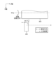
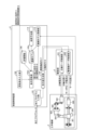
- FIG. 1 is a diagram showing the functional configuration of a numerical control device 1a according to the first embodiment.
- the numerical control device 1a has a function of controlling the machine tool 3 by outputting a drive axis command 17 and a spindle command 18, which are command values for controlling the machine tool 3, to the drive unit 2 according to the machining program 10.
- the drive unit 2 supplies the machine tool 3 with a spindle current 20 and a servo motor current 22 for controlling the machine tool 3 based on a drive axis command 17 and a spindle command 18 output by the numerical control device 1a.
- the drive unit 2 can generate a spindle current 20 based on the spindle position 21 fed back from the machine tool 3, and can generate a servo motor current 22 based on the drive axis position 23 fed back from the machine tool 3.
- the machine tool 3 has a main shaft 300 and a drive shaft 301, which are axes that change the relative positions of a workpiece 303 and a tool 304.
- a main shaft 300 and a drive shaft 301 By driving the drive shaft 301, the workpiece 303 is cut.
- the machine tool 3 can perform vibration cutting that causes chips to break up by vibrating at least one of the axes that change the relative positions of the workpiece 303 and the tool 304.
- the numerical control device 1a is an example of a drive condition determining device that determines the drive conditions of the machine tool 3.
- the driving conditions are conditions that define the driving state of the machine tool 3.
- the machining conditions for machining the workpiece into the desired shape, the vibration conditions that define the vibration frequency and vibration amplitude, and the control parameters that determine the control characteristics of the axis are determined by the drive conditions. It is one of a kind.
- the numerical control device 1a includes a search condition input section 100, a machining program input section 101, a condition search section 102, and a command value generation section 104.
- the search condition input unit 100 acquires conditions for searching for drive conditions.
- the search condition input unit 100 includes a search range set for at least one drive condition among machining conditions, vibration conditions, and control parameters, and a reference machining condition that is set regardless of the presence or absence of vibration cutting.
- a search condition including a certain standard processing condition 11 is acquired.
- the search condition input unit 100 inputs the standard machining conditions 11, the standard vibration conditions 12 which are the standard vibration conditions, and the vibration conditions which are the search range set for the vibration conditions.
- the condition search range 14 is acquired.
- the search condition input unit 100 outputs the acquired search conditions to the condition search unit 102.
- the search condition input unit 100 is configured using input means such as a keyboard, buttons, and a mouse, and receives input from an operator to the numerical control device 1a to obtain input information.
- the condition search unit 102 searches for drive conditions based on the search conditions output by the search condition input unit 100, and determines execution drive conditions that are actually used drive conditions.
- the execution drive conditions include execution machining conditions 15, which are actually used machining conditions, and execution vibration conditions 16, which are vibration conditions that are actually used. A detailed method by which the condition search unit 102 searches for driving conditions will be described later.
- the condition search unit 102 outputs the determined execution machining conditions 15 and execution vibration conditions 16.
- the machining program input unit 101 acquires the machining program 10 by receiving input of the machining program 10 for controlling the machine tool 3, and outputs the acquired machining program 10 to the command value generation unit 104.
- the command value generation unit 104 sends commands to the drive shaft 301 of the machine tool 3 based on the machining program 10 output by the machining program input unit 101 and the execution machining conditions 15 and execution vibration conditions 16 determined by the condition search unit 102.
- a drive shaft command 17, which is a command to the main shaft 300, and a main shaft command 18, which is a command to the main shaft 300, are generated, and the generated drive shaft command 17 and main shaft command 18 are output to the drive unit 2.
- the drive section 2 includes a main shaft servo control section 201 and a drive shaft servo control section 202.
- the spindle servo control unit 201 performs position control so that the spindle position 21 of the spindle motor 302 of the machine tool 3 matches the spindle command 18, and outputs the spindle current 20. However, when the spindle command 18 is a speed command, the spindle servo control unit 201 performs speed control so that the spindle speed matches the spindle command 18.
- the drive shaft servo control unit 202 performs position control so that the drive shaft position 23 of the servo motor 305 of the machine tool 3 matches the drive shaft command 17, and outputs the servo motor current 22.
- the drive shaft 301 is shown for simplicity, but if the machine tool 3 has two or more drive shafts 301, the drive section 2 It is also possible to have a plurality of drive shaft servo control sections 202 corresponding to each drive shaft servo control section 301.
- the machine tool 3 is a lathe-type machine and includes a main shaft 300, a drive shaft 301, a main shaft motor 302 connected to the main shaft, and a servo motor 305 connected to the drive shaft 301.
- a tool 304 is installed on the drive shaft 301, and a workpiece 303 is installed on the main shaft 300.
- the spindle motor 302 is supplied with the spindle current 20 generated by the spindle servo control section 201 of the drive section 2 based on the spindle command 18 .
- the servo motor 305 is supplied with the servo motor current 22 generated by the drive shaft servo control section 202 of the drive section 2 based on the drive shaft command 17 .
- the main shaft motor 302 drives the main shaft 300 according to the main shaft current 20, and the servo motor 305 drives the drive shaft 301 according to the servo motor current 22.
- the rotary table on which the tool 304 is installed and the drive shaft that drives the tool 304 are both driven by the drive shaft servo control section 202.
- the machine tool 3 is not limited to a machine that performs turning processing, but may be a machine that performs rolling processing.
- vibration cutting may be performed by rotating the tool 304. For example, drilling, milling, etc. are methods of cutting the workpiece 303 with a rotating tool 304.
- FIG. 2 is an explanatory diagram of vibration cutting using the machine tool 3 shown in FIG. 1.
- the main spindle 300 (not shown in FIG. 2) rotates the workpiece 303 at a constant speed according to the main spindle command 18.
- a Z-axis servo motor 305 is controlled based on a drive axis command 17, so that a Z-axis drive axis 301 rotates the tool specified in the machining program 10 while causing interference between the tool 304 and the workpiece 303.
- the tool 304 is moved in the Z-axis direction along the path.
- the drive axis command 17 includes a feed amount command specified in the execution machining condition 15 and an amplitude and frequency vibration command based on the execution vibration condition 16.
- the drive shaft command 17 causes the drive shaft 301 to vibrate while moving the tool 304 along the tool path, so that relative vibration occurs between the tool 304 and the workpiece 303 and chips are broken up.
- the tool 304 is vibrated by the drive shaft 301, but if it is possible to generate relative vibration between the tool 304 and the workpiece 303, the workpiece 303 can be vibrated using the main shaft 300.
- both the drive shaft 301 and the main shaft 300 may be used to vibrate both the tool 304 and the workpiece 303.
- relative vibration may be generated by vibration transmitted to the workpiece 303 side by the reaction force of the motor that drives the tool 304.
- a relative vibration may be generated using a drive shaft 301 (not shown) that is driven in the X-axis direction perpendicular to the Z-axis, or it may be vibrated in the slope direction while simultaneously driving the X-axis and the Z-axis. You can.
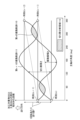
- FIG. 3 is an explanatory diagram of the mechanism by which chip fragmentation occurs during vibration cutting performed by the machine tool 3.
- the horizontal axis in FIG. 3 indicates the rotation angle of the main shaft 300. The rotation angle goes around once every 360 degrees and returns to 0 degrees.
- the vertical axis in FIG. 3 indicates the relative distance between the tool 304 and the workpiece 303 in the direction along the tool path. When vibration is not applied, each rotation moves by the feed amount F per rotation specified in the tool path.
- the tool 304 is vibrated while being sent in the Z-axis direction, so the relative distance between the workpiece 303 and the tool 304 during one rotation of the main shaft 300 is such that the vibration is sinusoidal. It becomes a trajectory. This trajectory is called a vibration trajectory.
- the example in FIG. 3 shows a vibration trajectory when the drive shaft 301 in the Z-axis direction is vibrated 1.5 times during one rotation of the main shaft 300.
- the vibration locus is determined by the spindle rotation speed S (r/min), the feed rate per rotation F (mm/r) which is the feed rate of the tool 304 to the workpiece 303 per spindle rotation, and the vibration amplitude A of the tool 304 ( mm) and the angular frequency of vibration of the tool 304 ⁇ v (rad/s).
- FIG. 3 shows an n-th vibration trajectory 110, which is the vibration trajectory during the n-th spindle rotation, and an (n+1)-th vibration trajectory 111, which is the vibration trajectory during the n+1-th spindle rotation.
- the n-th vibration trajectory 110 is a vibration trajectory between time t(n), which is the time when the main shaft 300 passes through 0 degrees, and time t(n+1), which is the time after the main shaft has made one revolution.
- the (n+1)th vibration locus 111 is a vibration locus between time t(n+1) and time t(n+2), which is the time after the main shaft has made one revolution.
- the time t(n) here may be an arbitrary reference time, for example, the reference time may be the time at which machining is started.
- the distance between the n-th vibration locus 110 and the (n+1)-th vibration locus 111 at the same main axis angle is the thickness of the chips, which is the chip thickness.
- the chip separation region 112, which is a hatched region in FIG. 3, is a region where the n-th vibration trajectory 110 and the (n+1)-th vibration trajectory 111 overlap. In this region, material has already been removed from the surface of the workpiece 303 at the n-th vibration locus 110, and therefore, at the n+1-th vibration locus 111, air cut occurs without material being removed. In the area sandwiched between the air cut areas, the chips are not continuous, so the chips are divided. Therefore, in order to generate chip fragmentation, it is desirable to set the driving conditions for vibration cutting so that an air cut region is generated.
- the spindle rotation speed S (r/min) and the feed rate per rotation F (mm/r) are given as machining conditions that should be determined in turning regardless of whether or not vibration cutting is performed, and the tool
- the vibration amplitude A (mm) of the relative vibration between 304 and the workpiece 303 and the angular frequency ⁇ v (rad/s) of the vibration are given, the angular frequency ⁇ s (rad/s) of the rotation of the main shaft is given. is determined by the following formula (1).
- Formula (4) is derived from Formula (2) and Formula (3).
- ⁇ is the phase difference between the n-th vibration locus 110 and the (n+1)-th vibration locus 111.
- the n-th vibration locus 110 and the (n+1)-th vibration locus 111 touch at a point.
- the conditions under which chip fragmentation occurs can be expressed by a mathematical formula. As long as the conditions shown in formulas (4) and (5) can be satisfied, processing conditions and vibration conditions can be freely selected. On the other hand, if a driving condition is set that does not satisfy either Equation (4) or Equation (5), vibration cutting will not occur because chips will not be separated.
- the operator uses the search condition input section 100 to input the spindle rotation speed and the feed rate per blade as the standard machining conditions 11.
- the standard machining conditions 11 may be information expressed in any format as long as the angular frequency of the spindle rotation and the feed amount per rotation can be uniquely determined.
- the standard machining conditions 11 may include information expressing the Z-axis feed rate in feed amount per minute (mm/min).
- the search condition input section 100 calculates the feed rate per blade from the input feed amount per minute, and sends the calculation result to the condition search section 102.
- the reference machining conditions 11 may directly include the angular frequency of the spindle rotation instead of the spindle rotation speed.
- the operator uses the search condition input unit 100 to input the vibration frequency and vibration amplitude, which are the reference vibration conditions 12, as search conditions. Furthermore, the operator uses the search condition input unit 100 to input the vibration condition search range 14, which is the search range of vibration conditions, as a search condition.
- the vibration condition search range 14 includes a vibration frequency search range and a vibration amplitude search range. Note that if the vibration frequency and vibration amplitude can be uniquely determined for the standard vibration conditions 12 and the vibration condition search range 14, the standard vibration conditions 12 and the vibration condition search range 14 can be information expressed in any format. There may be.
- the reference vibration condition 12 and the vibration condition search range 14 may include a value of vibration frequency as the number of vibrations per rotation of the spindle, or a value of vibration amplitude as a ratio to the feed rate per blade.
- search condition input section 100 converts the input values into vibration frequency and vibration amplitude and outputs them to condition search section 102.
- the condition search unit 102 determines execution drive conditions, which are drive conditions to be used when actually performing machining.
- the execution drive conditions determined by the condition search unit 102 include execution machining conditions 15, which are machining conditions used when actually machining, and vibration conditions used when actually machining.
- a certain execution vibration condition 16 is included.
- FIG. 4 is a flowchart for explaining the operation of the condition search unit 102 shown in FIG. 1.
- the condition search unit 102 first sets the reference machining conditions 11 and reference vibration conditions 12 included in the search conditions output by the search condition input unit 100 (step S1).
- the condition search unit 102 determines whether the set machining conditions and vibration conditions satisfy the dividing conditions (step S2).
- step S2 determines whether the vibration amplitude is adjustable (step S3), and if the vibration amplitude is adjustable (step S3: Yes). ), the vibration amplitude is changed within the vibration amplitude search range (step S4). After step S4, the condition search unit 102 returns to the process of step S2. In this case, the condition search unit 102 repeats the processes from step S2 to step S4 of changing the vibration amplitude and determining whether or not the dividing condition is satisfied, as long as the vibration amplitude can be adjusted, until the dividing condition is satisfied. It turns out.
- the condition search unit 102 starts from the lower limit value of the vibration amplitude search range and adds a constant value each time the vibration amplitude search range is changed, thereby increasing the value of the vibration amplitude from the lower limit value to the upper limit value of the vibration amplitude search range. You can explore. In this case, in step S3, if the value of the vibration amplitude after the change has not reached the upper limit value, the condition search unit 102 determines that the vibration amplitude can be adjusted, and the value of the vibration amplitude after the change is the upper limit value. , it can be determined that the vibration amplitude is not adjustable.
- step S3 If the vibration amplitude is not adjustable (step S3: No), the condition search unit 102 changes the vibration frequency within the vibration frequency search range (step S5). At this time, the condition search unit 102 sets the value of the vibration amplitude to the lower limit value of the vibration amplitude search range, and returns to the process of step S2.
- step S6 When the dividing conditions are satisfied (step S2: Yes), the condition search unit 102 outputs the set machining conditions and vibration conditions as execution drive conditions (step S6).
- the condition search unit 102 outputs the standard machining conditions 11 and the standard vibration conditions 12 as execution drive conditions, and If the reference vibration condition 12 does not satisfy the dividing condition, first, a vibration condition that satisfies the dividing condition is searched for while changing the vibration amplitude by a constant value from the lower limit value to the upper limit value of the vibration amplitude search range. Even if the vibration amplitude reaches the upper limit value, if a vibration condition that satisfies the dividing condition is not found, then the condition search unit 102 changes the vibration frequency to the lower limit value, changes the vibration amplitude to the lower limit value, and then increases the vibration amplitude.
- the condition search unit 102 finds a combination of vibration amplitude and vibration frequency that satisfies the dividing condition within the search range. You can explore.
- the numerical control device 1a performs vibration cutting in which the shaft that changes the relative position of the workpiece 303 and the tool 304 is vibrated during cutting to break up chips.
- a drive condition determination device that determines drive conditions of a machine tool 3 to perform processing, the vibration conditions that define the vibration frequency and vibration amplitude of at least one of the drive shaft 301 and the main shaft 300 to be vibrated; and a search range set for at least one drive condition of the control parameters, which are parameters that determine the control characteristics of the axis, and a reference machining, which is the standard machining conditions determined regardless of the presence or absence of vibration cutting.
- the apparatus includes a condition search unit 102 that determines execution drive conditions that are drive conditions used when performing vibration cutting. Therefore, even if the operator is unable to appropriately determine the drive conditions for the machine tool 3 when performing vibration cutting, the drive conditions are searched within the set search range and chip fragmentation occurs. Since it is possible to automatically determine the driving conditions, it is possible to increase the possibility that chips will break up when the machine tool performs vibration cutting.
- FIG. 5 is a diagram showing the functional configuration of the information processing device 1b according to the second embodiment.
- the information processing device 1b is an example of a drive condition determining device that determines the drive conditions of the machine tool 3.
- components similar to those in Embodiment 1 will be denoted by the same reference numerals and detailed explanations will be omitted, and portions that are different from Embodiment 1 will be mainly described.
- the information processing device 1b is a device that is installed inside a computer and determines machining conditions and vibration conditions that are drive conditions when performing vibration cutting with the machine tool 3.
- the information processing device 1b inputs the standard machining conditions 11, the standard vibration conditions 12, and the vibration condition search range 14, and outputs the execution machining conditions 15 and the execution vibration conditions 16 to the machining program generation device 103.
- the machining program generation device 103 is CAM (Computer Aided Manufacturing) software that generates a machining program 10 for the machine tool 3 called an EIA program or G code from machining path generation information.
- the machining program generation device 103 generates the spindle rotation speed, feed amount per tooth, vibration frequency, and vibration amplitude for a machining program that describes a machining path to be machined under the standard machining conditions 11 output by CAM software or the like. It may be software that additionally edits information corresponding to a command and outputs the edited machining program 10.
- the information processing device 1b includes a search condition input section 100 and a condition search section 102b.
- the condition search unit 102b determines execution drive conditions using a machine model 105 that simulates the characteristics of the machine tool 3.
- the drive shaft 301 vibrates with the same vibration amplitude as the vibration amplitude commanded to the drive shaft servo control unit 202.
- the amplitude of the relative vibration between the tool 304 and the workpiece 303 is , may differ from the commanded vibration amplitude. In such cases, even if the commanded vibration amplitude and vibration frequency satisfy the chip breaking conditions, the vibration amplitude generated during actual machining is different from the command value, so chip breaking may not occur. be.
- the condition search unit 102b of the information processing device 1b searches for vibration conditions using a machine model 105 that simulates the mechanical characteristics of the machine tool 3, taking into account the difference between the command value and the actual value of vibration amplitude. . Specifically, the condition search unit 102b uses the machine model 105 to estimate the actual vibration amplitude at the tip position of the tool 304 with respect to the commanded vibration amplitude, and the value of the estimated vibration amplitude satisfies the cutting condition. Search for vibration conditions that satisfy.
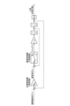
- FIG. 6 is a diagram showing an example of the machine model 105 shown in FIG.
- FIG. 6 shows a mechanical model 105 that simulates the mechanical characteristics of the drive shaft servo control unit 202 and the drive shaft 301 in the frequency domain.
- the drive shaft servo control unit 202 has a controller that controls the position x of the tip of the tool 304 in response to the drive shaft command 17r, and has a cascade type control structure that has a speed control loop inside the position control loop.
- the position control includes a P (Proportion) controller which is a position controller that calculates the speed command vr by multiplying the difference in the tool tip position x with respect to the drive axis command 17r by the position loop gain K p .
- P Proportion
- the speed controller adds the result of multiplying the difference between the speed command vr and the tool tip speed v by the speed loop gain Kvp and the result of multiplying and integrating the speed integral gain Kvi , and controls the servo motor 305.
- It has a PI (Proportion Integral) controller which is a speed controller that calculates the torque Tr output by the motor.
- this machine model 105 calculates the tool tip speed v by multiplying and integrating the torque command by J that simulates the total moment of inertia of the drive shaft 301, and by integrating the tool tip speed v, the tool tip Calculate the position x.
- s is a Laplace operator, and "1/s" represents an integral operation.
- the machine model 105 described above is just an example, and any model may be used as long as it can calculate the response of the tool tip position to the position command.
- a controller other than the P controller or PI controller may be used, or the characteristics of the drive shaft 301 may be expressed by a transfer function instead of the total moment of inertia.
- a current control loop for calculating the servo motor current 22 output from the servo motor 305 may be provided inside the speed control loop. At this time, the torque Tr is calculated by multiplying the motor current by a torque constant for calculating the motor torque from the motor current.
- a model described as a discrete system using difference equations may be used as the machine model 105.
- FIG. 7 is a flowchart for explaining a first example of the operation of the condition search unit 102b shown in FIG. 5.
- the processing from step S1 to step S6 is the same as that in FIG. In FIG. 7, before determining whether the dividing condition is satisfied in step S2, the condition search unit 102b estimates the vibration amplitude using the mechanical model 105 (step S7).
- the condition search unit 102b uses the machine model 105 to calculate the actual vibration amplitude between the tool 304 and the workpiece 303 from the set vibration amplitude.
- a method of calculating the vibration amplitude using the model expressed by the above equation (7) will be described.
- Equation (8) the response at a certain frequency ⁇ can be calculated by substituting j ⁇ for s in Equation (7).
- j is an imaginary unit.
- the actual vibration output between the tool 304 and the workpiece 303 can be calculated as a mathematical formula, so for the set vibration amplitude A, The actual vibration amplitude A' between the tool 304 and the workpiece 303 can be calculated using the set vibration frequency ⁇ v and Equation (9).
- the input vibration has a single frequency ⁇
- the input vibration waveform may be a rectangular wave, a triangular wave, etc.
- a rectangular wave-like vibration command can be obtained using a Fourier series at a frequency (2 ⁇ -1) It is known that it can be described as the sum of simple harmonic motions of ⁇ .
- Equation (10) and Equation (9) it is possible to calculate the amplitude for a rectangular wave vibration command.
- the amplitude ratio may be calculated by approximating it as a function of only the first-order frequency component.
- the amplitude ratio can be similarly calculated for commands simulating triangular waves and other periodic vibrations.
- step S2 of FIG. 7 the condition search unit 102b uses the vibration amplitude A' calculated in step S7 instead of the set vibration amplitude A to determine whether the dividing condition is satisfied.
- FIG. 8 is a flowchart for explaining a second example of the operation of the condition search unit 102b shown in FIG.
- the actual vibration amplitude A' is calculated before determining whether the dividing condition is satisfied, but in the second example shown in FIG.
- the vibration amplitude is corrected based on the mechanical model 105 before outputting it as an execution drive condition (step S8).
- the condition search unit 102b searches for the vibration amplitude A and the vibration frequency ⁇ v that satisfy the dividing condition, so that the vibration amplitude between the tool 304 and the workpiece 303 matches A. By multiplying the vibration amplitude A by the reciprocal of formula (9), the corrected vibration amplitude A'' is calculated. In step S6, the condition search unit 102b outputs the execution drive condition including the corrected vibration amplitude A''.
- the actual vibration amplitude value was calculated from the vibration amplitude command value using a mathematical formula, but the method for estimating the actual vibration amplitude value is not limited to the above example.
- the condition search unit 102b experimentally determines the actual vibration amplitude value using a mathematical formula, data table, etc. that approximates the actual vibration amplitude value experimentally derived for the vibration amplitude command value. may be estimated.
- the condition search unit 102b uses a discrete system model described by a difference equation instead of formula (7), and performs conversion from a discrete system model to a continuous system model called bilinear transformation or Tustin transformation. The amplitude ratio may be calculated by converting into a continuous system using the formula.
- condition search unit 102b may calculate the response waveform from the model through numerical simulation, and calculate the amplitude ratio from the response waveform obtained through the simulation.
- FIG. 9 is a diagram showing the relationship between the response amplitude and the vibration amplitude command value, which is experimentally derived.
- FIG. 9 is a diagram called a Bode diagram, in which a sine wave signal or random noise with a continuously changing frequency is commanded to a servo motor, and the vibration between the tool 304 and the workpiece 303 at that time is accelerated. It can be obtained by measuring using a sensor, displacement sensor, etc. In this figure, the ratio of output amplitude to input amplitude is calculated at each frequency.
- 0 dB means that the input amplitude and output amplitude match; if the gain is larger than 0 dB, the output amplitude will be larger than the input amplitude, and if the gain is smaller than 0 dB, the output amplitude will be larger than the input amplitude. This means that the amplitude is smaller.
- the actual vibration amplitude relative to the input vibration amplitude command value can be determined without using numerical calculations. For example, the characteristics of the Bode diagram may be approximated by a mathematical formula, or table data may be used in the machine model 105 to calculate the actual value of the vibration amplitude.
- the condition search unit 102b uses the mechanical model 105 to estimate the actual vibration amplitude at the tip position of the tool 304 from the drive axis command for the axis. Based on the obtained vibration amplitude, a drive condition that satisfies the dividing condition is searched. Since the estimated value of the actual vibration amplitude is used instead of the command value of the vibration amplitude to determine whether or not the breaking condition is satisfied, the possibility of chip breakage occurring when the machine tool 3 performs vibration cutting can be more reliably determined. It becomes possible to increase the
- FIG. 10 is a diagram showing the functional configuration of the information processing device 1c according to the third embodiment.
- the information processing device 1c is an example of a driving condition determining device.
- the information processing device 1c includes a search condition input section 100c and a condition search section 102c.
- the search condition input unit 100c acquires the standard machining condition 11, the standard vibration condition 12, the machining condition search range 13, and the vibration condition search range 14 as search conditions.
- the condition search unit 102c uses the machine model 105c and the evaluation function 106 to search for drive conditions.
- FIG. 11 is a diagram showing an example of the machine model 105c shown in FIG. 10.
- the difference between the machine model 105c and the machine model 105 of the second embodiment is that the machine model 105c has a machine end transfer function model Gm(s).
- Gm machine end transfer function model
- control is performed so that the position detected by the detector matches the commanded position.
- the object whose vibration amplitude should truly be controlled is the relative vibration between the tool 304 and the workpiece 303, but relative displacement between the tool 304 and the workpiece 303 is It is difficult to install a detector to detect this. Therefore, feedback control is performed using a detector attached to the servo motor 305, and the actual relative vibration between the tool 304 and the workpiece 303 is estimated using the machine end transfer function model Gm(s).
- the machine end model is measured by, for example, installing an acceleration sensor on each of the tool 304 and the workpiece 303.
- the transfer function may be identified by curve fitting by differentiating the detector signal twice when the motor is driven, drawing a Bode diagram that inputs the acceleration signal and outputs the relative acceleration, or identifies the transfer function using a finite element
- a transfer function calculated from a model of the structure of the machine tool 3 by the Finite Element Method (FEM) may be used, or a state space model output from an element composition matrix of the FEM model may be used.
- FEM Finite Element Method
- FIG. 12 is a flowchart for explaining the operation of the condition search unit 102c shown in FIG. 10.
- the condition search unit 102c first sets the standard machining conditions 11 and the standard vibration conditions 12 (step S1). Subsequently, the condition search unit 102c estimates the actual vibration amplitude using the mechanical model 105c (step S7). The condition search unit 102c determines whether the set machining conditions and vibration conditions satisfy the dividing conditions (step S2). At this time, the condition search unit 102c uses the actual vibration amplitude estimated in step S7 as the vibration amplitude of the vibration condition.
- step S3 determines whether the vibration amplitude can be adjusted. If the vibration amplitude is adjustable (step S3: Yes), the condition search unit 102c changes the vibration amplitude within the vibration amplitude search range (step S4), and returns to the process of step S7.
- step S3 determines whether the vibration amplitude is adjustable (step S9). If the vibration frequency is adjustable (step S9: Yes), the condition search unit 102c changes the vibration frequency within the vibration frequency search range (step S5), and returns to the process of step S7.
- step S9 determines whether the vibration frequency is adjustable (step S10). If the spindle rotation speed is adjustable (step S10: Yes), the condition search unit 102c changes the spindle rotation speed within the rotation speed search range (step S11), and returns to the process of step S7.
- step S10 determines whether the feed amount is adjustable (step S12). If the feed amount is adjustable (step S12: Yes), the condition search unit 102c changes the feed amount within the feed amount search range (step S13), and returns to the process of step S7.
- step S12 If the feed amount cannot be adjusted (step S12: No), a search failure is output (step S14) and the process ends.
- step S2 If the dividing condition is satisfied (step S2: Yes), the condition search unit 102c next determines whether the set machining conditions and vibration conditions satisfy the first evaluation function (step S15). If the first evaluation function is not satisfied (step S15: No), the condition search unit 102c proceeds to the process of step S3. If the first evaluation function is satisfied (step S15: Yes), the condition search unit 102c outputs the set machining conditions and vibration conditions as execution drive conditions (step S6).
- the first evaluation function is a function for evaluating the searched machining conditions and vibration conditions. Even if the searched machining conditions and vibration conditions satisfy the chip breaking conditions, if machining takes too long or the load on the machine tool 3 is too large, machining may be performed using such machining conditions and vibration conditions. It is not recommended to do so. Therefore, the information processing device 1c uses an evaluation function to determine whether the searched combination of processing conditions and vibration conditions is appropriate.
- the first evaluation function is a linear sum of any one or more of the following: electrical energy required for vibration, vibration acceleration, machining time, cutting volume, maximum machining load, amount of machine wear, and cumulative vibration cutting time. It is expressed as For example, the first evaluation function can be set to "V>100" using the cutting volume V (mm 3 /min).
- the cutting volume V can be expressed by the following formula (11) using the spindle rotation speed S, the feed rate per tooth F, the radial depth of cut h, and the diameter R (mm) of the workpiece 303. .
- the first evaluation function may simply be that the spindle rotation speed is greater than or equal to the lower limit value, or may be that the feed amount is greater than or equal to the lower limit value. Alternatively, the first evaluation function may be a combination of these.
- each condition in the step of changing each condition within the search range, each condition can be changed by a constant value from the lower limit value to the upper limit value of the search range.
- it in the step of determining whether each condition is adjustable, it can be determined whether each condition is adjustable based on whether the value after the change exceeds the upper limit.
- step S5 the vibration amplitude is changed to the lower limit value of the vibration amplitude search range
- step S11 the vibration amplitude is changed to the lower limit value of the vibration amplitude search range, and the vibration frequency is changed to the lower limit value of the vibration frequency search range.
- step S13 the vibration amplitude is changed to the lower limit value of the vibration amplitude search range, the vibration frequency is changed to the lower limit value of the vibration frequency search range, and the spindle rotation speed is changed to the lower limit value of the rotation speed search range. change.
- the search may fail. If a driving condition that satisfies both the dividing condition and the first evaluation function is not found, the user is notified of the search failure in step S14. In this case, the user can reset the search range and redo the search.
- the search is terminated when one driving condition that satisfies both the dividing condition and the first evaluation function is found, but within all search ranges, candidates for execution driving conditions that satisfy the dividing condition are found.
- the execution driving condition may be determined based on the first evaluation function by searching for a plurality of candidates. In this case, when a plurality of candidates exist, it becomes possible to use conditions suitable for processing among the plurality of candidates.
- the condition search unit 102c searches for execution drive condition candidates that satisfy the dividing condition, and performs cutting using the searched candidates. Based on the first evaluation function for evaluation, it can be determined whether or not the searched candidate is to be the execution driving condition. As a result, even if the cutting conditions are met, conditions for which the evaluation of the cutting process is low, such as conditions that take too much time or place too much load on the machine tool 3, can be prevented from being set as the execution driving conditions. It becomes possible.
- the first evaluation function is based on any one or more of the energy required to generate vibration, vibration acceleration, machining time, cutting volume, maximum machining load, amount of machine wear, and cumulative vibration cutting time. It can be a function expressed as a linear sum of parameters. This makes it possible to evaluate the cutting process based on these parameters.
- the energy required to generate vibration is determined by "1/2 MA 2 ⁇ v 2 " when expressed in vibration energy, where M is the mass of the shaft that performs vibration cutting.
- a value obtained by converting the above-mentioned vibrational energy into electrical energy may be used as the energy required to generate the vibration.
- the value obtained by dividing the vibrational energy by a coefficient representing the efficiency of converting electrical energy into vibrational energy can be determined as the energy required to generate the vibration.
- machining time calculate the shaft movement amount SF per minute based on the feed rate F per revolution and the spindle rotation speed S, and calculate the total machining distance L for vibration cutting by the shaft movement amount per minute. By dividing by SF, the machining time "L/SF" can be calculated.
- the maximum machining load is calculated as “K c AF/1000” using the specific cutting force K c determined from the material properties of the workpiece 303. Further, the amount of machine wear is calculated by accumulating the vibration cutting time up to now and multiplying the cumulative vibration cutting time by a coefficient determined experimentally.
- the evaluation function Z is divided into two evaluation functions with coefficients P 1 and P 2 , as expressed by the following formula (12). It can be found as a linear sum of However, the coefficients P 1 and P 2 can take any predetermined real numbers.
- a search failure is notified, so the user can change the search condition.
- the driving conditions can be searched again.
- FIG. 13 is a diagram showing a functional configuration of an information processing device 1c-2 according to a modification of the third embodiment. In comparison with the information processing device 1c, the information processing device 1c-2 shown in FIG. The difference is that it has -2.
- the AI model 107 is a trained model that outputs the actual vibration amplitude at the tip position of the tool 304 when the command value of vibration amplitude, spindle rotation speed, feed rate per tooth, and vibration frequency are input.
- the AI model 107 may be, for example, a model trained by artificial intelligence using an algorithm such as a neural network, reinforcement learning, or Q-learning.
- FIG. 14 is a diagram showing the functional configuration of the numerical control device 1d according to the fourth embodiment.
- the numerical control device 1d includes a search condition input section 100, a machining program input section 101, a condition search section 102d, and a command value generation section 104.
- the numerical control device 1d is different from the numerical control device 1a in that the inputs to the search condition input section 100 are the standard machining conditions 11, the machining condition search range 13, and the vibration condition search range 14, and the machine model 105 and evaluation function 106 as inputs. Note that in the numerical control device 1d, the reference vibration condition is not included in the input to the search condition input section 100. Therefore, at the start of the search, the search is started from the lower limit of the vibration condition search range, the upper limit of the vibration condition search range, the intermediate value of the vibration condition search range, or the initial search conditions set in advance using parameters, etc. It turns out.
- FIG. 15 is a flowchart for explaining the operation of the condition search unit 102d shown in FIG. 14. Here, differences from the condition search unit 102c of the third embodiment shown in FIG. 12 will be explained.
- the condition search unit 102d further determines whether or not the second evaluation function is satisfied (step S17).
- step S17: Yes If the second evaluation function is satisfied (step S17: Yes), the condition search unit 102d returns to step S3 and continues searching for conditions without adopting the set conditions. If the second evaluation function is not satisfied (step S17: No), the condition search unit 102d proceeds to step S6.
- step S12 the condition search unit 102 sets drive conditions that include the standard machining condition 11 and does not perform vibration cutting (step S16), and then proceeds to step S6. move on.
- Step S17 in FIG. 15 functions as a safety device, and when "an abnormality occurs when vibration cutting is performed using the set machining conditions and vibration conditions", the step S17 is set to "satisfy the second evaluation function".
- the second evaluation function is set.
- the second evaluation function is It is filled.
- Examples of electrical equipment equipped on the machine tool 3 include a numerical control device, a drive device called a drive unit, a motor, an electromagnetic switch, and a relay.
- An example of the second evaluation function is a function using vibration energy H, power consumption, and vibration amplitude. Further, the same function may be used as the first evaluation function and the second evaluation function, and different threshold values may be provided.
- the first evaluation function assumes that the machining time is 3 minutes or more
- the second evaluation function assumes that the machining time is 10 minutes or more. In this case, if the machining time is less than 3 minutes, the first evaluation function is not satisfied, and if the machining time is 10 minutes or more, the second evaluation function is satisfied, so the set drive condition is not selected. Therefore, only when the machining condition is 3 minutes or more and less than 10 minutes is output as the execution drive condition.
- an evaluation function setting section may be provided in which the user sets arbitrary conditions as the first evaluation function and the second evaluation function.
- the second evaluation function also includes electrical energy required to generate vibration, vibration acceleration, machining time, cutting volume, maximum machining load, amount of machine wear, and cumulative vibration cutting time. It can be a function expressed by a linear sum of any one or more of the following.
- the first evaluation function is preferably a function that can determine that vibration cutting using the driving conditions is suitable when the first evaluation function is satisfied, and the second evaluation function is , when the second evaluation function is satisfied, the function can be used to determine that it is desirable not to adopt the drive condition as the execution drive condition, such as when an abnormality occurs in vibration cutting using the drive condition. desirable.
- the machining load and the amount of wear are predicted by a machining simulation using the machine model 105. Further, the cumulative vibration cutting time is set in a memory that records the total time of vibration cutting performed so far.
- an evaluation function using the number of chips that can be separated by vibration cutting in one rotation can be considered. For example, if chips are separated too many times during one rotation, the servo motor 305 is loaded and generates heat.
- the number of times the chips are divided per rotation as an evaluation function, it is possible to search for driving conditions so as to obtain an appropriate number of times the chips are divided.
- condition search unit 102d of the numerical control device 1d selects candidates for execution drive conditions that satisfy the dividing condition, and determines whether or not an abnormality will occur in the cutting process using the candidates. If it is evaluated that an abnormality occurs in the cutting process using the candidate, the candidate is not set as the execution driving condition. Thereby, even if the cutting conditions are met, it is possible to prevent driving conditions from being selected that would cause an abnormality in the cutting process.
- the condition search unit 102d determines a drive condition that includes standard machining condition 11 and does not perform vibration cutting as an execution drive condition. be able to. In this case, if no driving conditions are found that would result in no abnormalities using the second evaluation function, priority is given to performing cutting that does not cause abnormalities without performing vibration cutting. can do.
- FIG. 16 is a diagram showing the functional configuration of the information processing device 1e according to the fifth embodiment.
- the information processing device 1e has a condition search unit 102e in place of the condition search unit 102c, in which the information input to the search condition input unit 100 is a reference processing condition 11, a vibration condition search range 14, and a control parameter search range 19. This differs from the third embodiment in this point.
- the inputs to the information processing device 1e are the standard machining conditions 11, the vibration condition search range 14, and the control parameter change range 19, and the output from the information processing device 1e is the execution machining conditions 15, the execution vibration conditions 16, and the control parameters. It is 24.
- the reference vibration condition is not included in the input to the search condition input section 100. Therefore, at the start of the search, the search is started from the lower limit of the vibration condition search range, the upper limit of the vibration condition search range, the intermediate value of the vibration condition search range, or the initial search conditions set in advance using parameters, etc. It turns out.
- FIG. 17 is a flowchart for explaining the operation of the condition search unit 102e shown in FIG. 16.
- the condition search unit 102e sets the standard processing conditions 11 (step S1e).
- the condition search unit 102e determines whether the set condition satisfies the dividing condition (step S2). If the dividing condition is not satisfied (step S2: No), the condition search unit 102e determines whether the vibration amplitude can be adjusted (step S3). If the vibration amplitude is adjustable (step S3: Yes), the condition search unit 102e changes the vibration amplitude within the vibration amplitude search range (step S4), and returns to the process of step S2.
- step S3 determines whether the vibration amplitude is adjustable (step S9). If the vibration frequency is adjustable (step S9: Yes), the condition search unit 102e changes the vibration frequency within the vibration frequency search range (step S5), and returns to the process of step S2.
- step S9 determines whether the vibration frequency is adjustable (step S9: No). If the vibration frequency is not adjustable (step S9: No), the condition search unit 102e determines whether the control parameters are adjustable (step S18). If the control parameter is adjustable (step S18: Yes), the condition search unit 102e changes the control parameter within the control parameter adjustment range (step S19), and returns to the process of step S2.
- step S18 If the control parameters cannot be adjusted (step S18: No), the condition search unit 102e sets drive conditions that include the reference machining conditions 11 and does not perform vibration cutting (step S16), and adjusts the set machining conditions, vibration conditions, and The control parameters are output as execution driving conditions (step S6e).
- step S2 If the dividing condition is satisfied (step S2: Yes), the condition search unit 102e corrects the vibration amplitude based on the mechanical model 105 (step S8).
- the condition search unit 102e determines whether the set drive condition satisfies the second evaluation function (step S17). If the second evaluation function is satisfied (step S17: Yes), the condition search unit 102e proceeds to the process of step S3; if the second evaluation function is not satisfied (step S17: No), the condition search unit 102e The process advances to step S6e.
- control parameters are searched in addition to vibration conditions.
- the control parameters are, for example, a position loop gain K p , a velocity loop gain K vp , and a velocity integral gain K vi .
- the control parameter is a parameter that determines the control characteristics of the drive shaft 301, and as shown in equation (10), the control parameter affects the calculation of the vibration amplitude. For this reason, even under the same vibration conditions, whether or not chips will break apart will vary depending on the magnitude of the control parameter.
- the control parameter to be changed may be only the position loop gain Kp, or both the position loop gain Kp and the velocity loop gain Kvp .
- the parameters to be changed may be determined in advance, or may be arbitrarily selected by the user for each process. Furthermore, when using a model other than the illustrated mechanical model 105, control parameters that affect vibration amplitude can be searched for in the model used. By searching for control parameters, it is possible to increase the possibility of searching for drive conditions that can break up chips.
- phase margin is the phase margin from -180 degrees when the gain is 0 dB in the control system, and generally, if a phase margin of 30 degrees or more is secured, the control system will be stabilized. Further, the gain margin is the gain margin from 0 dB when the phase is -180 degrees.
- FIG. 18 is a diagram showing the functional configuration of the numerical control device 1f according to the sixth embodiment.
- the numerical control device 1f has a mechanical model updating unit that updates the mechanical model 105c based on the measured value of the vibration amplitude output by the acceleration sensor 306 that measures the vibration amplitude. 113, and a failure prediction unit 114 that predicts a failure of the machine tool 3 based on aging of the machine model 105c.
- the mechanical model 105c is the same as the mechanical model 105c shown in FIG. 11.
- the reference vibration condition is not included in the input to the search condition input section 100. Therefore, at the start of the search, the search is started from the lower limit of the vibration condition search range, the upper limit of the vibration condition search range, the intermediate value of the vibration condition search range, or the initial search conditions set in advance using parameters, etc. It turns out.
- the vibration characteristics of the machine tool 3 gradually change over time. For example, vibrations in mechanical structures may increase due to loosening of fasteners, fatigue failure of structural members, loss of preload in bearings or ball screws, and the like. Additionally, the load on the motor may increase due to increased friction. If vibration cutting is continued in this state, the machine tool 3 may break down. Therefore, the numerical control device 1f has a function of monitoring the secular change of the machine tool 3 from the difference between the vibration amplitude predicted by calculation and the actual vibration amplitude, and predicting a failure before it actually occurs. , the machine tool 3 can be repaired at an appropriate time.
- the acceleration sensor 306 is installed on the drive shaft 301. In FIG. 18, the acceleration sensor 306 is attached to the nut of the ball screw, but it may be attached, for example, inside the tool holder of the tool 304, or to the turret on which the tool of a lathe is attached.
- the acceleration sensor 306 measures the vibration level during vibration cutting and transmits it to the machine model update unit 113.
- the machine model updating unit 113 compares the calculated value of the vibration amplitude calculated from the execution machining conditions 15 and the execution vibration conditions 16 with the actual measured value of the vibration amplitude.
- Gm(s) that simulates the characteristics of the drive shaft 301 in the mechanical model 105c is changed. This makes it possible to accurately estimate the vibration amplitude even if the mechanical properties change.
- the failure prediction unit 114 monitors the change history of the machine model 105c. If the amount of change in the machine model 105c exceeds a predetermined threshold, it is determined that the aging of the machine tool 3 has exceeded the allowable value and a failure has occurred, and a warning is output to the user.
- the method of outputting the warning is not particularly limited, and the warning may be issued by screen display or by audio output. However, the failure prediction unit 114 may make a determination based on whether the current amount of change in the machine model 105c exceeds a threshold, or may predict that the threshold will be exceeded in the future for a certain period of time and output a warning. .
- the numerical control device 1f can handle the case where the mechanical characteristics change by changing the control parameters in accordance with the change in the machine model 105c due to aging of the machine tool 3. This has the effect that the vibration amplitude can be accurately estimated even when the vibration amplitude is low. Furthermore, by detecting the occurrence of a failure or a sign of the occurrence of a failure based on the amount of change in the machine model 105c, it is possible to make a repair or repair plan in advance, and prevent production from stopping due to a sudden failure. This makes it possible to avoid such situations.
- FIG. 19 is a diagram showing the functional configuration of an information processing device 1g according to the seventh embodiment.
- the information processing device 1g includes a search condition input section 100, a condition search section 102g, and a learned model storage section 120.
- the condition search unit 102g includes a learning data acquisition unit 40 and a model generation unit 41.
- the learning data acquisition unit 40 receives the standard machining conditions 11 and the standard vibration conditions 12 from the search condition input unit 100, and also performs vibration cutting on the control parameters 24, tool information 30, workpiece information 31, and motion information 32 for each axis. Obtain as learning data.
- the tool information 30 includes information indicating the tool material and tool shape.
- the workpiece information 31 includes information indicating the material of the workpiece.
- the motion information 32 for each axis includes information indicating the feed rate of each axis and the acceleration of each axis.
- the model generation unit 41 uses the machine model 105, the machined surface quality determination model 42, and the chip division determination model 43 to satisfy the dividing condition based on the vibration cutting learning data acquired by the learning data acquisition unit 40.
- the execution drive conditions the execution drive conditions that give the best cutting quality are learned.
- the model generation unit 41 receives the standard machining conditions 11, the standard vibration conditions 12, the control parameters 24, the motion information 32 of each axis, the workpiece information 31, and the tool information 30, and generates the dividing conditions.
- a condition/control parameter search model 48 that outputs a combination of execution machining conditions 15, execution vibration conditions 16, and control parameters 24 such that the machining quality of cutting satisfies the standards is output as a learning result.
- the operation information 32 of each axis is information indicating the operation position of the motor of each axis of the machine tool 3, and the model generation unit 41 generates information about the machine tool 3 from the operation information 32 of each axis and the control parameters 24.
- the machine model 105 is used to obtain information indicating the movement of the mechanical structure attached to each axis. That is, the machine model 105 receives the operation information 32 and control parameters 24 of each axis as input, and outputs information indicating the movement of the mechanical structure attached to each axis of the machine tool 3.
- the model generation unit 41 uses the chip division determination model 43 in order to determine whether or not division of chips occurs, that is, to determine whether or not division conditions are satisfied.
- the chip division determination model 43 receives the output of the machine model 105, the standard machining conditions 11, the standard vibration conditions 12, and the control parameters 24, and outputs a determination result as to whether or not chip division occurs. Furthermore, the model generation unit 41 uses the machined surface quality determination model 42 to determine whether the machining quality of cutting using the driving conditions determined to cause chip fragmentation satisfies the standard. The machined surface quality determination model 42 determines whether the result of machining the workpiece 303 is good or bad based on the motion information 32 of each axis. The machined surface quality determination model 42 receives as input the output of the machine model 105, the drive conditions determined to satisfy the dividing condition using the chip division determination model 43, the workpiece information 31, and the tool information 30.
- Processing quality is determined based on the smoothness of the machined surface.
- the machined surface quality determination model 42 can evaluate the machining quality using the variation or maximum error amount of each tool path with respect to the average line or average surface calculated based on the arithmetic mean for the tool path.
- the machined surface quality determination model 42 may estimate the machined surface by also considering the shape of the tool 304, and evaluate the processing quality using the cusp height after the workpiece 303 is removed.
- the quality determination portion of the machined surface described above may be modeled as the machined surface quality determination model 42 and included in the learning target.
- the machined surface quality determination model 42 may be one that calculates the machined surface of the workpiece 303 based on the relative displacement between the tool 304 and the workpiece 303.
- the relative displacement may be a command to the motor, a motor end response calculated using a motor characteristic model, or a machine end response calculated using a mechanical characteristic model.
- the calculation may be performed using only the relative displacement between the tool 304 and the workpiece 303, or the relative displacement may be calculated by geometrically taking into consideration the shape of the tool 304. It may be corrected, or the quality of the machined surface may be calculated based on the theory of physical cutting phenomena, taking into account the materials of the tool 304 and the workpiece 303.
- the machined surface quality determination model 42 may be replaced with a data set acquired using the actual machine tool 3. For example, in addition to machining conditions and vibration conditions, you can create learning data by linking a data set of tool shape, tool material, and workpiece material, and information on surface quality when machining under the conditions of the data set. Can be set.
- the model generation unit 41 uses the machine model, the machined surface quality determination model 42, and the chip separation determination model 43 to calculate the machining conditions, vibration conditions, and control parameters based on the vibration cutting learning data described above. Learn combinations. That is, a learned model is generated that infers drive conditions including at least one of machining conditions, vibration conditions, and control parameters from the vibration cutting learning data described above.
- the learning process of the model generation unit 41 will be explained.
- known algorithms such as supervised learning, unsupervised learning, and reinforcement learning can be used.
- reinforcement learning an agent, which is the main actor in an environment, observes the parameters of the environment that indicate its current state and decides what action to take. The environment changes dynamically depending on the actions of the agent, and the agent is rewarded according to changes in the environment. The agent repeats this process and learns the course of action that yields the most rewards through a series of actions.
- Q-learning and TD-learning are known as typical methods of reinforcement learning.
- a general update formula for the action value function Q(s, a) is expressed by the following equation (13).
- Equation (13) s t represents the state of the environment at time t, and a t represents the behavior at time t.
- the action a t changes the state to s t+1 .
- r t+1 represents the reward received by changing the state
- ⁇ represents the discount rate
- ⁇ represents the learning coefficient. Note that ⁇ is in the range of 0 ⁇ 1, and ⁇ is in the range of 0 ⁇ 1.
- the selection of machining conditions, vibration conditions, and control parameters becomes action a t , and the determination of whether chips are divided or not and the machined surface quality information become state s t , and the best action a t in state s t at time t is learned. do.
- the update formula expressed by formula (13) is that if the action value Q of action a with the highest Q value at time t+1 is greater than the action value Q of action a executed at time t, then the action value Q is increased. However, in the opposite case, the action value Q is decreased. In other words, the action value function Q(s, a) is updated so that the action value Q of action a at time t approaches the best action value at time t+1. As a result, the best action value in a certain environment will be successively propagated to the action value in the previous environment.
- the model generation unit 41 when generating a trained model by reinforcement learning, the model generation unit 41 includes a reward calculation unit 44 and a function update unit 45.
- the reward calculation unit 44 calculates the reward r based on the selection of machining conditions, vibration conditions, and control parameters, the determination of whether chips are divided, and the machined surface quality information.
- the criteria for determining remuneration are as follows. For example, if the machined surface quality information improves, that is, if the dispersion and maximum error amount of each tool path described above decreases, or if the cusp height decreases, the reward r is increased (for example, the reward r is "1"). On the other hand, if the machined surface quality information deteriorates, the reward r is reduced (for example, a reward of "-1" is given).
- the reward r is increased, and if it is determined that the chips are not divided, the reward r is decreased. Since fragmentation of chips is essential to exhibit the effect of vibration cutting, if it is determined that there is no fragmentation, the reward r is greatly reduced (for example, a reward of "-5" is given).
- the function update unit 45 updates a function for determining a combination of machining conditions, vibration conditions, and control parameters according to the reward calculated by the reward calculation unit 44, and outputs it to the learned model storage unit 120.
- the action value function Q (s t , a t ) expressed by equation (13) is used as a function for calculating a combination of processing conditions, vibration conditions, and control parameters.
- the learned model storage unit stores the action value function Q(s t , a t ) updated by the function update unit 45, that is, the learned model.
- FIG. 20 is a flowchart regarding the learning process of the condition search unit 102g shown in FIG. 19.
- the learning data acquisition unit 40 performs data acquisition to acquire machining conditions, vibration conditions, and control parameters as learning data (step S31).
- the model generation unit 41 calculates the reward based on the selection of machining conditions, vibration conditions, and control parameters, the determination of whether chips are divided, and the machined surface quality information (step S32). Specifically, the reward calculation unit 44 uses each of the above-mentioned models to determine whether chips are divided and to obtain machined surface quality information based on the selection of a combination of machining conditions, vibration conditions, and control parameters. Determine whether to increase or decrease remuneration based on predetermined remuneration judgment criteria.
- step S32 remuneration increase criterion
- step S33 increases the remuneration
- step S34 reduces the remuneration
- the function update unit 45 updates the action value function Q(s t , a t ) expressed by formula (13) stored in the learned model storage unit 120 based on the reward calculated by the reward calculation unit 44. (Step S35).
- the condition search unit 102g repeatedly executes the steps from step S31 to step S35, and stores the generated action value function Q(s t , a t ) as a learned model.
- the information processing device 1g stores the learned model in the learned model storage section 120 provided inside the information processing device 1g.
- the unit 120 may be provided outside the information processing device 1g.
- the information processing device 1g by using artificial intelligence to learn processing phenomena that involve complex phenomena using information during processing, workers who do not have processing know-how can However, the effect is that the optimum chip separation conditions can be easily found.
- model generation unit 41 As a learning algorithm used in the model generation unit 41, deep learning, which learns the extraction of the feature values themselves, can be used, and other known methods such as neural networks, genetic programming, functional Machine learning may be performed according to logic programming, support vector machines, etc.
- the model generation unit 41 may learn a combination of machining conditions, vibration conditions, and control parameters using learning data acquired from a plurality of numerical control devices.
- the model generation unit 41 may acquire learning data from a plurality of numerical control devices used in the same area, or may obtain learning data collected from a plurality of numerical control devices that operate independently in different areas. Combinations of machining conditions, vibration conditions, and control parameters may be learned using the data.
- an information processing device that has learned the combination of machining conditions, vibration conditions, and control parameters for a certain numerical control device is applied to another numerical control device, and the combination of machining conditions, vibration conditions, and control parameters for that other numerical control device is learned. The combination of control parameters may be re-learned and updated.
- FIG. 21 is a diagram showing the functional configuration of a numerical control device 1h according to the eighth embodiment.
- inference is performed using the learned model generated in the seventh embodiment.
- the condition search unit 102h includes an inference data acquisition unit 46 and an inference unit 47.
- the inference data acquisition unit 46 acquires the above vibration cutting learning data as inference data.
- the inference unit 47 uses the learned model to infer a combination of machining conditions, vibration conditions, and control parameters from the inference data. That is, the inference unit 47 inputs the vibration cutting learning data acquired by the inference data acquisition unit 46 into the condition/control parameter search model 48, which is a trained model, thereby dividing the chips and creating a good machined surface. It is possible to infer a combination of machining conditions, vibration conditions, and control parameters that will yield quality.
- a trained model is acquired from an external device different from the numerical control device 1h, such as an external personal computer, a storage area on a network, etc., and processing conditions and settings are determined based on the acquired trained model.
- a combination of vibration conditions and control parameters may be output.
- a combination of machining conditions, vibration conditions, and control parameters is output using a learned model learned by the model generation unit 41 of the information processing device.
- a learned model generated by learning in the model generation unit 41 built in the numerical control device 1h is also possible.
- the inference data acquisition unit 46 acquires vibration cutting learning data.
- the vibration cutting learning data only needs to include at least the reference vibration condition 12 and the reference machining condition 11 as described above, but it is possible to improve the accuracy of inference by adding information other than these. can be expected.
- the inference unit 47 inputs the vibration cutting learning data, which is data for inference, to the condition/control parameter search model 48, which is the acquired learned model, to obtain a combination of machining conditions, vibration conditions, and control parameters.
- the inference unit 47 outputs the obtained combination of machining conditions, vibration conditions, and control parameters to the command value generation unit 104.
- the command value generation unit 104 generates a drive axis command and a main axis command using the output combination of the machining conditions, vibration conditions, and control parameters, and outputs them to the drive unit 2 (not shown in FIG. 21). Thereby, vibration cutting can be performed under the optimal conditions that are estimated by the trained model and that achieve both the occurrence of chip fragmentation and good machined surface quality.
- FIG. 22 is a flowchart for explaining the inference processing of the numerical control device 1h shown in FIG. 21.
- the inference data acquisition unit 46 acquires the above-mentioned vibration cutting learning data as inference data (step S41).
- the inference unit 47 inputs vibration cutting learning data, which is inference data, to the learned model (step S42), and obtains a combination of the execution machining conditions 15, the execution vibration conditions 16, and the control parameters 24.
- the inference section 47 performs data output to output the obtained combination of the execution machining conditions 15, the execution vibration conditions 16, and the control parameters 24 to the command value generation section 104 (step S43).
- the command value generation unit 104 generates a command value using the inference result (step S44).
- reinforcement learning is applied to the learning algorithm used by the inference unit 47, but the invention is not limited to this.
- learning algorithm in addition to reinforcement learning, supervised learning, unsupervised learning, semi-supervised learning, etc. can also be applied.
- the numerical control device 1h in Embodiment 8 has the effect that by performing vibration cutting using a model learned by artificial intelligence, the operator can perform optimal vibration cutting without having to judge the machining state. play.
- the functional units of the numerical control devices 1a, 1d, 1f, and 1h are realized using processing circuits.
- the processing circuit may be realized by dedicated hardware or may be a control circuit using a CPU (Central Processing Unit).
- FIG. 23 is a diagram showing dedicated hardware for realizing the functions of the numerical control devices 1a, 1d, 1f, and 1h according to the first, fourth, sixth, and eighth embodiments.
- the processing circuit 90 is a single circuit, a composite circuit, a programmed processor, a parallel programmed processor, an ASIC (Application Specific Integrated Circuit), an FPGA (Field Programmable Gate Array), or a combination thereof.
- FIG. 24 is a diagram showing the configuration of a control circuit 91 for realizing the functions of the numerical control devices 1a, 1d, 1f, and 1h according to the first, fourth, sixth, and eighth embodiments.
- the control circuit 91 includes a processor 92 and a memory 93.
- the processor 92 is a CPU, and is also called a processing device, arithmetic device, microprocessor, microcomputer, DSP (Digital Signal Processor), or the like.
- the memory 93 is, for example, a non-volatile or volatile semiconductor memory such as RAM (Random Access Memory), ROM (Read Only Memory), flash memory, EPROM (Erasable Programmable ROM), EEPROM (registered trademark) (Electrically EPROM), These include magnetic disks, flexible disks, optical disks, compact disks, mini disks, and DVDs (Digital Versatile Disks).
- RAM Random Access Memory
- ROM Read Only Memory
- flash memory EPROM (Erasable Programmable ROM), EEPROM (registered trademark) (Electrically EPROM)
- magnetic disks flexible disks, optical disks, compact disks, mini disks, and DVDs (Digital Versatile Disks).
- the above processing circuit is implemented using the control circuit 91, it is implemented by the processor 92 reading and executing a program stored in the memory 93 that corresponds to the processing of each component.
- the memory 93 is also used as a temporary memory in each process executed by the processor 92.
- the information processing devices 1b, 1c, 1c-2, 1e, and 1g of this embodiment are, for example, Realized by a computer system.
- the information processing devices 1b, 1c, 1c-2, 1e, and 1g may be realized by one computer system, or may be realized by multiple computer systems.
- the information processing devices 1b, 1c, 1c-2, 1e, and 1g may be realized by a cloud system.
- a cloud system it is possible to arbitrarily set up the separation between computer system hardware and devices such as servers for each function.
- one computer system may function as multiple devices, or multiple computer systems may function as one device.
- FIG. 25 is a diagram showing a configuration example of a computer system that implements information processing apparatuses 1b, 1c, 1c-2, 1e, and 1g according to Embodiments 2, 3, 5, and 7.
- this computer system includes a control section 401, an input section 402, a storage section 403, a display section 404, a communication section 405, and an output section 406, which are connected via a system bus 407. There is.
- the control unit 401 is, for example, a CPU.
- the control unit 401 executes each process described in the information processing apparatuses 1b, 1c, 1c-2, 1e, and 1g of this embodiment.
- the input unit 402 includes, for example, a keyboard, a mouse, etc., and is used by a user of the computer system to input various information.
- the storage unit 403 includes various memories such as RAM (Random Access Memory) and ROM (Read Only Memory), and storage devices such as hard disks, and stores programs to be executed by the control unit 401 and necessary information obtained in the process of processing. Store data etc.
- the storage unit 403 is also used as a temporary storage area for programs.
- the display unit 404 is configured with an LCD (Liquid Crystal Display) or the like, and displays various screens to the user of the computer system.
- the communication unit 405 is a communication circuit or the like that performs communication processing.
- the communication unit 405 may be configured with a plurality of communication circuits each corresponding to a plurality of communication methods.
- the output unit 406 is an output interface that outputs data to an external device such as a printer or an external storage device.
- FIG. 25 is an example, and the configuration of the computer system is not limited to the example of FIG. 25.
- the computer system may not include the output unit 406.
- the information processing apparatuses 1b, 1c, 1c-2, 1e, and 1g are realized by a plurality of computer systems, all of these computer systems do not need to be the computer systems shown in FIG. 25.
- some computer systems may not include at least one of the display section 404, output section 406, and input section 402 shown in FIG. 25.
- a drive condition determination program is installed in the storage unit 403 from a CD-ROM or DVD-ROM set in a CD (Compact Disc)-ROM drive or DVD-ROM drive (not shown). be done.
- the drive condition determination program is executed, the drive condition determination program read from the storage section 403 is stored in an area of the storage section 403 that serves as a main storage device.
- the control unit 401 executes processing as the information processing apparatuses 1b, 1c, 1c-2, 1e, and 1g of this embodiment according to the drive condition determination program stored in the storage unit 403.
- a program is provided that describes processing in the information processing apparatuses 1b, 1c, 1c-2, 1e, and 1g using a CD-ROM or DVD-ROM as a recording medium, but this is not limited to this.
- a program provided via a transmission medium such as the Internet via the communication unit 405 may be used.
- the drive condition determination program of this embodiment is a drive condition that determines the drive conditions of a machine tool that performs vibration cutting in which the axis that changes the relative position of the workpiece and the tool vibrates during cutting to break up chips.
- the determination program includes a search range set for at least one drive condition among machining conditions of a machine tool, vibration conditions of an axis, and a control parameter that is a parameter that determines control characteristics of the axis, and vibration cutting. a step of obtaining search conditions including standard machining conditions 11, which are the standard machining conditions that are determined regardless of the presence or absence of the process; and satisfying a dividing condition, which is a condition under which chip division occurs, based on the search conditions.
- the computer is caused to perform the steps of determining execution drive conditions, which are drive conditions used when performing vibration cutting, within the range in which the search range is set.
- the search condition input unit 100 of the information processing devices 1b, 1c, 1c-2, 1e, and 1g is realized by the input unit 402.
- the condition search units 102b, 102c, 102c-2, and 102e of the information processing devices 1b, 1c, 1c-2, 1e, and 1g are realized by the control unit 401.
- the machine models 105 and 105c and the evaluation function 106 are stored in the storage unit 403.
- the division of functions in each device shown in the figure is an example, and if the above-mentioned operations can be performed, division of functions in each device is possible. It is not limited to the example shown in FIG.
- the information processing devices 1b, 1c, 1c-2, 1e, and 1g may be realized by the same computer system as the machining program generation device 103.
- the hardware configuration has been described assuming that the information processing device is connected to a numerical control device via a network, and is a separate device from the numerical control device.
- the information processing device may be built into the numerical control device.
- the information processing device may exist on a cloud server.
Landscapes
- Engineering & Computer Science (AREA)
- Physics & Mathematics (AREA)
- Geometry (AREA)
- Human Computer Interaction (AREA)
- Manufacturing & Machinery (AREA)
- General Physics & Mathematics (AREA)
- Automation & Control Theory (AREA)
- Mechanical Engineering (AREA)
- Numerical Control (AREA)
- Turning (AREA)
Priority Applications (4)
| Application Number | Priority Date | Filing Date | Title |
|---|---|---|---|
| DE112022007137.0T DE112022007137T5 (de) | 2022-08-05 | 2022-08-05 | Antriebseinstellung-Bestimmungsgerät und Antriebseinstellung-Bestimmungsverfahren |
| JP2022576887A JP7313585B1 (ja) | 2022-08-05 | 2022-08-05 | 駆動条件決定装置および駆動条件決定方法 |
| CN202280097332.9A CN119404160A (zh) | 2022-08-05 | 2022-08-05 | 驱动条件决定装置及驱动条件决定方法 |
| PCT/JP2022/030109 WO2024029074A1 (ja) | 2022-08-05 | 2022-08-05 | 駆動条件決定装置および駆動条件決定方法 |
Applications Claiming Priority (1)
| Application Number | Priority Date | Filing Date | Title |
|---|---|---|---|
| PCT/JP2022/030109 WO2024029074A1 (ja) | 2022-08-05 | 2022-08-05 | 駆動条件決定装置および駆動条件決定方法 |
Publications (1)
| Publication Number | Publication Date |
|---|---|
| WO2024029074A1 true WO2024029074A1 (ja) | 2024-02-08 |
Family
ID=87428168
Family Applications (1)
| Application Number | Title | Priority Date | Filing Date |
|---|---|---|---|
| PCT/JP2022/030109 Ceased WO2024029074A1 (ja) | 2022-08-05 | 2022-08-05 | 駆動条件決定装置および駆動条件決定方法 |
Country Status (4)
| Country | Link |
|---|---|
| JP (1) | JP7313585B1 (https=) |
| CN (1) | CN119404160A (https=) |
| DE (1) | DE112022007137T5 (https=) |
| WO (1) | WO2024029074A1 (https=) |
Cited By (1)
| Publication number | Priority date | Publication date | Assignee | Title |
|---|---|---|---|---|
| JP7710621B1 (ja) * | 2024-05-27 | 2025-07-18 | 三菱電機株式会社 | 設定支援装置、数値制御装置、設定支援方法およびプログラム |
Families Citing this family (3)
| Publication number | Priority date | Publication date | Assignee | Title |
|---|---|---|---|---|
| WO2025253427A1 (ja) * | 2024-06-03 | 2025-12-11 | ファナック株式会社 | 加工プログラム補正装置 |
| JP7741265B1 (ja) * | 2024-09-03 | 2025-09-17 | 株式会社牧野フライス製作所 | 工作機械、加工方法 |
| JP7814640B1 (ja) * | 2025-06-20 | 2026-02-16 | 三菱電機株式会社 | 数値制御装置および数値制御方法 |
Citations (6)
| Publication number | Priority date | Publication date | Assignee | Title |
|---|---|---|---|---|
| JP2018043306A (ja) * | 2016-09-13 | 2018-03-22 | シチズン時計株式会社 | 工作機械およびその制御装置 |
| JP2019166604A (ja) * | 2018-03-23 | 2019-10-03 | シチズン時計株式会社 | 切削装置及びその制御方法 |
| JP2020144588A (ja) * | 2019-03-06 | 2020-09-10 | ファナック株式会社 | 工作機械の制御装置 |
| WO2020217614A1 (ja) * | 2019-04-26 | 2020-10-29 | 三菱電機株式会社 | 加工条件決定支援装置及び機械学習装置 |
| JP6843313B1 (ja) * | 2020-06-03 | 2021-03-17 | 三菱電機株式会社 | 制御システム |
| WO2022153936A1 (ja) * | 2021-01-14 | 2022-07-21 | ファナック株式会社 | 機械学習装置 |
Family Cites Families (7)
| Publication number | Priority date | Publication date | Assignee | Title |
|---|---|---|---|---|
| EP3561620B1 (en) * | 2016-12-22 | 2023-08-02 | Citizen Watch Co., Ltd. | Machine tool and control device therefor |
| JP6503000B2 (ja) * | 2017-04-18 | 2019-04-17 | ファナック株式会社 | 揺動切削を行う工作機械の制御装置 |
| JP6708690B2 (ja) * | 2018-04-05 | 2020-06-10 | ファナック株式会社 | 表示装置 |
| CN109226803B (zh) * | 2018-11-08 | 2020-06-09 | 上海交通大学 | 基于简谐振动断屑的自适应钻削加工方法 |
| JP7522180B2 (ja) * | 2020-02-20 | 2024-07-24 | ファナック株式会社 | 工作機械の制御装置 |
| CN112685872B (zh) * | 2020-11-23 | 2024-09-20 | 南京航空航天大学 | 一种用于低频振动辅助钻孔加工的工艺优化方法 |
| US20240272603A1 (en) * | 2021-06-15 | 2024-08-15 | Fanuc Corporation | Information processing device, device for controlling machine tool, and non-transitory computer-readable medium storing a computer program |
-
2022
- 2022-08-05 JP JP2022576887A patent/JP7313585B1/ja active Active
- 2022-08-05 CN CN202280097332.9A patent/CN119404160A/zh active Pending
- 2022-08-05 DE DE112022007137.0T patent/DE112022007137T5/de active Pending
- 2022-08-05 WO PCT/JP2022/030109 patent/WO2024029074A1/ja not_active Ceased
Patent Citations (6)
| Publication number | Priority date | Publication date | Assignee | Title |
|---|---|---|---|---|
| JP2018043306A (ja) * | 2016-09-13 | 2018-03-22 | シチズン時計株式会社 | 工作機械およびその制御装置 |
| JP2019166604A (ja) * | 2018-03-23 | 2019-10-03 | シチズン時計株式会社 | 切削装置及びその制御方法 |
| JP2020144588A (ja) * | 2019-03-06 | 2020-09-10 | ファナック株式会社 | 工作機械の制御装置 |
| WO2020217614A1 (ja) * | 2019-04-26 | 2020-10-29 | 三菱電機株式会社 | 加工条件決定支援装置及び機械学習装置 |
| JP6843313B1 (ja) * | 2020-06-03 | 2021-03-17 | 三菱電機株式会社 | 制御システム |
| WO2022153936A1 (ja) * | 2021-01-14 | 2022-07-21 | ファナック株式会社 | 機械学習装置 |
Cited By (1)
| Publication number | Priority date | Publication date | Assignee | Title |
|---|---|---|---|---|
| JP7710621B1 (ja) * | 2024-05-27 | 2025-07-18 | 三菱電機株式会社 | 設定支援装置、数値制御装置、設定支援方法およびプログラム |
Also Published As
| Publication number | Publication date |
|---|---|
| JPWO2024029074A1 (https=) | 2024-02-08 |
| JP7313585B1 (ja) | 2023-07-24 |
| DE112022007137T5 (de) | 2025-02-27 |
| CN119404160A (zh) | 2025-02-07 |
Similar Documents
| Publication | Publication Date | Title |
|---|---|---|
| JP7313585B1 (ja) | 駆動条件決定装置および駆動条件決定方法 | |
| US10921774B2 (en) | Machine learning devices and methods for optimizing the speed and accuracy of thread mill, inner diameter, outer shape, and surface machine tools | |
| JP6567205B1 (ja) | 機械学習装置、補正パラメータ調整装置および機械学習方法 | |
| JP6697491B2 (ja) | 機械学習装置、サーボモータ制御装置、サーボモータ制御システム、及び機械学習方法 | |
| JP4812224B2 (ja) | Nc加工における加工シミュレーション装置及び方法 | |
| JP6740277B2 (ja) | 機械学習装置、制御装置、及び機械学習方法 | |
| CN111722530B (zh) | 机器学习装置、控制系统以及机器学习方法 | |
| JP2021182431A (ja) | 制御システム、工場システム、学習システム、推定用モデルの生成方法及びアクチュエータの状態推定方法 | |
| JP2013225284A (ja) | 動作システムのパラメータ推定法、そのパラメータ推定システム、動作プロファイルの生成方法およびその生成システム | |
| US11921489B2 (en) | Numerical control device, learning apparatus, inference apparatus, and numerical control method | |
| JP6806746B2 (ja) | モータ制御装置 | |
| JP6748135B2 (ja) | 機械学習装置、サーボ制御装置、サーボ制御システム、及び機械学習方法 | |
| JP7022261B1 (ja) | 周波数特性予測装置及び周波数特性予測方法 | |
| CN110658785A (zh) | 输出装置、控制装置、以及评价函数值的输出方法 | |
| JP2017103882A (ja) | 制御装置、制御プログラムおよび記録媒体 | |
| JP2020123191A (ja) | 数値制御システム | |
| JP6880322B2 (ja) | 数値制御装置 | |
| CN110376964A (zh) | 机器学习装置、控制装置以及机器学习方法 | |
| JP6978452B2 (ja) | 機械学習装置、制御装置、及び機械学習の探索範囲の設定方法 | |
| CN110875703A (zh) | 机器学习装置、控制系统以及机器学习方法 | |
| CN116635802B (zh) | 数控装置 | |
| CN110888398A (zh) | 控制装置、cnc装置以及控制方法 | |
| JP7385298B2 (ja) | 既存のサーボドライブ変数を使用したモーションシステムの状態管理 | |
| WO2023053399A1 (ja) | 数値制御装置、加工システム、数値制御方法および加工方法 | |
| JP6740290B2 (ja) | 機械学習装置、制御装置、及び機械学習方法 |
Legal Events
| Date | Code | Title | Description |
|---|---|---|---|
| ENP | Entry into the national phase |
Ref document number: 2022576887 Country of ref document: JP Kind code of ref document: A |
|
| 121 | Ep: the epo has been informed by wipo that ep was designated in this application |
Ref document number: 22954062 Country of ref document: EP Kind code of ref document: A1 |
|
| WWE | Wipo information: entry into national phase |
Ref document number: 112022007137 Country of ref document: DE |
|
| WWE | Wipo information: entry into national phase |
Ref document number: 202280097332.9 Country of ref document: CN |
|
| WWP | Wipo information: published in national office |
Ref document number: 202280097332.9 Country of ref document: CN |
|
| WWP | Wipo information: published in national office |
Ref document number: 112022007137 Country of ref document: DE |
|
| 122 | Ep: pct application non-entry in european phase |
Ref document number: 22954062 Country of ref document: EP Kind code of ref document: A1 |