WO2024029074A1 - 駆動条件決定装置および駆動条件決定方法 - Google Patents
駆動条件決定装置および駆動条件決定方法 Download PDFInfo
- Publication number
- WO2024029074A1 WO2024029074A1 PCT/JP2022/030109 JP2022030109W WO2024029074A1 WO 2024029074 A1 WO2024029074 A1 WO 2024029074A1 JP 2022030109 W JP2022030109 W JP 2022030109W WO 2024029074 A1 WO2024029074 A1 WO 2024029074A1
- Authority
- WO
- WIPO (PCT)
- Prior art keywords
- condition
- vibration
- conditions
- drive
- search
- Prior art date
Links
- 238000000034 method Methods 0.000 title claims description 47
- 238000005520 cutting process Methods 0.000 claims abstract description 114
- 238000012545 processing Methods 0.000 claims abstract description 40
- 238000003754 machining Methods 0.000 claims description 136
- 238000011156 evaluation Methods 0.000 claims description 67
- 230000001133 acceleration Effects 0.000 claims description 16
- 239000000463 material Substances 0.000 claims description 14
- 230000005856 abnormality Effects 0.000 claims description 9
- 230000001186 cumulative effect Effects 0.000 claims description 8
- 230000008859 change Effects 0.000 abstract description 23
- 230000006870 function Effects 0.000 description 97
- 230000010365 information processing Effects 0.000 description 53
- 238000010586 diagram Methods 0.000 description 39
- 230000008569 process Effects 0.000 description 27
- 230000009471 action Effects 0.000 description 24
- 238000003860 storage Methods 0.000 description 20
- 238000004364 calculation method Methods 0.000 description 15
- 238000013467 fragmentation Methods 0.000 description 14
- 238000006062 fragmentation reaction Methods 0.000 description 14
- 230000033001 locomotion Effects 0.000 description 11
- 230000015654 memory Effects 0.000 description 11
- 230000004044 response Effects 0.000 description 11
- 238000004422 calculation algorithm Methods 0.000 description 10
- 238000013473 artificial intelligence Methods 0.000 description 9
- 238000004891 communication Methods 0.000 description 9
- 230000002787 reinforcement Effects 0.000 description 8
- 238000012546 transfer Methods 0.000 description 7
- 238000006073 displacement reaction Methods 0.000 description 6
- 238000000926 separation method Methods 0.000 description 6
- 230000000694 effects Effects 0.000 description 5
- 239000003795 chemical substances by application Substances 0.000 description 4
- 230000032683 aging Effects 0.000 description 3
- 230000007423 decrease Effects 0.000 description 3
- 238000004088 simulation Methods 0.000 description 3
- 238000013528 artificial neural network Methods 0.000 description 2
- 238000006243 chemical reaction Methods 0.000 description 2
- 230000003247 decreasing effect Effects 0.000 description 2
- 230000002068 genetic effect Effects 0.000 description 2
- 238000004519 manufacturing process Methods 0.000 description 2
- 230000007246 mechanism Effects 0.000 description 2
- 230000004048 modification Effects 0.000 description 2
- 238000012986 modification Methods 0.000 description 2
- 238000005457 optimization Methods 0.000 description 2
- 230000008439 repair process Effects 0.000 description 2
- 230000009466 transformation Effects 0.000 description 2
- 238000007514 turning Methods 0.000 description 2
- 238000013459 approach Methods 0.000 description 1
- 230000006399 behavior Effects 0.000 description 1
- 230000005540 biological transmission Effects 0.000 description 1
- 239000002131 composite material Substances 0.000 description 1
- 238000013135 deep learning Methods 0.000 description 1
- 230000007547 defect Effects 0.000 description 1
- 239000006185 dispersion Substances 0.000 description 1
- 238000005553 drilling Methods 0.000 description 1
- 238000005516 engineering process Methods 0.000 description 1
- 238000000605 extraction Methods 0.000 description 1
- 239000004973 liquid crystal related substance Substances 0.000 description 1
- 238000010801 machine learning Methods 0.000 description 1
- 239000011159 matrix material Substances 0.000 description 1
- 238000003801 milling Methods 0.000 description 1
- 239000000203 mixture Substances 0.000 description 1
- 238000012544 monitoring process Methods 0.000 description 1
- 230000003287 optical effect Effects 0.000 description 1
- 230000000737 periodic effect Effects 0.000 description 1
- 230000036316 preload Effects 0.000 description 1
- 230000000644 propagated effect Effects 0.000 description 1
- 230000009467 reduction Effects 0.000 description 1
- 238000005096 rolling process Methods 0.000 description 1
- 239000004065 semiconductor Substances 0.000 description 1
- 238000004904 shortening Methods 0.000 description 1
- 238000012706 support-vector machine Methods 0.000 description 1
Images


Classifications
-
- B—PERFORMING OPERATIONS; TRANSPORTING
- B23—MACHINE TOOLS; METAL-WORKING NOT OTHERWISE PROVIDED FOR
- B23B—TURNING; BORING
- B23B1/00—Methods for turning or working essentially requiring the use of turning-machines; Use of auxiliary equipment in connection with such methods
-
- G—PHYSICS
- G05—CONTROLLING; REGULATING
- G05B—CONTROL OR REGULATING SYSTEMS IN GENERAL; FUNCTIONAL ELEMENTS OF SUCH SYSTEMS; MONITORING OR TESTING ARRANGEMENTS FOR SUCH SYSTEMS OR ELEMENTS
- G05B19/00—Programme-control systems
- G05B19/02—Programme-control systems electric
- G05B19/18—Numerical control [NC], i.e. automatically operating machines, in particular machine tools, e.g. in a manufacturing environment, so as to execute positioning, movement or co-ordinated operations by means of programme data in numerical form
- G05B19/4093—Numerical control [NC], i.e. automatically operating machines, in particular machine tools, e.g. in a manufacturing environment, so as to execute positioning, movement or co-ordinated operations by means of programme data in numerical form characterised by part programming, e.g. entry of geometrical information as taken from a technical drawing, combining this with machining and material information to obtain control information, named part programme, for the NC machine
-
- G—PHYSICS
- G05—CONTROLLING; REGULATING
- G05B—CONTROL OR REGULATING SYSTEMS IN GENERAL; FUNCTIONAL ELEMENTS OF SUCH SYSTEMS; MONITORING OR TESTING ARRANGEMENTS FOR SUCH SYSTEMS OR ELEMENTS
- G05B19/00—Programme-control systems
- G05B19/02—Programme-control systems electric
- G05B19/18—Numerical control [NC], i.e. automatically operating machines, in particular machine tools, e.g. in a manufacturing environment, so as to execute positioning, movement or co-ordinated operations by means of programme data in numerical form
- G05B19/4155—Numerical control [NC], i.e. automatically operating machines, in particular machine tools, e.g. in a manufacturing environment, so as to execute positioning, movement or co-ordinated operations by means of programme data in numerical form characterised by programme execution, i.e. part programme or machine function execution, e.g. selection of a programme
-
- Y—GENERAL TAGGING OF NEW TECHNOLOGICAL DEVELOPMENTS; GENERAL TAGGING OF CROSS-SECTIONAL TECHNOLOGIES SPANNING OVER SEVERAL SECTIONS OF THE IPC; TECHNICAL SUBJECTS COVERED BY FORMER USPC CROSS-REFERENCE ART COLLECTIONS [XRACs] AND DIGESTS
- Y02—TECHNOLOGIES OR APPLICATIONS FOR MITIGATION OR ADAPTATION AGAINST CLIMATE CHANGE
- Y02P—CLIMATE CHANGE MITIGATION TECHNOLOGIES IN THE PRODUCTION OR PROCESSING OF GOODS
- Y02P70/00—Climate change mitigation technologies in the production process for final industrial or consumer products
- Y02P70/10—Greenhouse gas [GHG] capture, material saving, heat recovery or other energy efficient measures, e.g. motor control, characterised by manufacturing processes, e.g. for rolling metal or metal working
Definitions
- the present disclosure relates to a drive condition determining device and a drive condition determining method for determining the drive conditions of a machine tool that performs vibration cutting.
- a machine tool used for cutting removes material from the surface of the workpiece and achieves a desired shape by performing relative motion while causing interference between the workpiece and the tool. At this time, the removed material is discharged as chips. When long chips are generated, they become entangled with the workpiece, tools, etc., reducing machining accuracy and causing scratches on the machined surface, causing machining defects.
- Patent Document 1 discloses that in order to avoid generating long chips, the axis that drives the tool is vibrated at a low frequency to create a moment when the tool and the workpiece do not interfere, thereby shortening the chips.
- a control device for a machine tool that performs vibratory cutting that separates is disclosed.
- the control device disclosed in Patent Document 1 performs multiple control operations based on tool data, the relative positional relationship between the workpiece and the tool, and movement data for relatively moving the workpiece and the tool. When one specific axis among the feed axes is vibrated, it is determined whether or not chips will break up, and the axis to be vibrated is automatically selected.
- the present disclosure has been made in view of the above, and aims to provide a drive condition determining device that can increase the possibility of chip fragmentation occurring when a machine tool performs vibration cutting. .
- a drive condition determining device vibrates a shaft that changes the relative position of a workpiece and a tool during cutting to break up chips.
- a drive condition determining device that determines the drive conditions of a machine tool that performs cutting, the drive condition determining device driving at least one of the machining conditions of the machine tool, the vibration conditions of the axis, and the control parameters that are parameters that determine the control characteristics of the axis.
- a search condition input section that obtains search conditions including a search range set for the conditions and standard machining conditions that are standard machining conditions determined regardless of the presence or absence of vibration cutting; a condition search unit that determines execution drive conditions that are drive conditions used when performing vibration cutting within a set search range so as to satisfy a breakup condition that causes chip breakage; It is characterized by having the following.
- the drive condition determining device has the effect that it is possible to obtain a drive condition determining device that can increase the possibility of chip fragmentation occurring when a machine tool performs vibration cutting.
- FIG. 1 A diagram showing a functional configuration of a numerical control device according to Embodiment 1 Explanatory diagram of vibration cutting using the machine tool shown in Figure 1 An explanatory diagram of the mechanism by which chips break up during vibration cutting performed by machine tools.
- Flowchart for explaining the operation of the condition search unit shown in FIG. 1 A diagram showing a functional configuration of an information processing device according to a second embodiment Diagram showing an example of the machine model shown in Figure 5 Flowchart for explaining the first example of the operation of the condition search unit shown in FIG. 5 Flowchart for explaining a second example of the operation of the condition search unit shown in FIG. 5 A diagram showing the relationship between the response amplitude and the vibration amplitude command value derived experimentally.
- FIG. 10 A diagram showing the functional configuration of an information processing device according to Embodiment 3 A diagram showing an example of the machine model shown in FIG. Flowchart for explaining the operation of the condition search unit shown in FIG. 10 A diagram showing a functional configuration of an information processing device according to a modification of Embodiment 3 A diagram showing the functional configuration of a numerical control device according to Embodiment 4 Flowchart for explaining the operation of the condition search unit shown in FIG. 14 A diagram showing the functional configuration of an information processing device according to Embodiment 5 Flowchart for explaining the operation of the condition search unit shown in FIG.
- a diagram showing a functional configuration of a numerical control device according to a sixth embodiment A diagram showing the functional configuration of an information processing device according to Embodiment 7 Flowchart related to the learning process of the condition search unit shown in FIG. 19
- a diagram showing the functional configuration of a numerical control device according to Embodiment 8 Flowchart for explaining inference processing of the numerical control device shown in FIG. 21
- FIG. 1 is a diagram showing the functional configuration of a numerical control device 1a according to the first embodiment.
- the numerical control device 1a has a function of controlling the machine tool 3 by outputting a drive axis command 17 and a spindle command 18, which are command values for controlling the machine tool 3, to the drive unit 2 according to the machining program 10.
- the drive unit 2 supplies the machine tool 3 with a spindle current 20 and a servo motor current 22 for controlling the machine tool 3 based on a drive axis command 17 and a spindle command 18 output by the numerical control device 1a.
- the drive unit 2 can generate a spindle current 20 based on the spindle position 21 fed back from the machine tool 3, and can generate a servo motor current 22 based on the drive axis position 23 fed back from the machine tool 3.
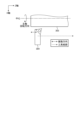
- the machine tool 3 has a main shaft 300 and a drive shaft 301, which are axes that change the relative positions of a workpiece 303 and a tool 304.
- a main shaft 300 and a drive shaft 301 By driving the drive shaft 301, the workpiece 303 is cut.
- the machine tool 3 can perform vibration cutting that causes chips to break up by vibrating at least one of the axes that change the relative positions of the workpiece 303 and the tool 304.
- the numerical control device 1a is an example of a drive condition determining device that determines the drive conditions of the machine tool 3.
- the driving conditions are conditions that define the driving state of the machine tool 3.
- the machining conditions for machining the workpiece into the desired shape, the vibration conditions that define the vibration frequency and vibration amplitude, and the control parameters that determine the control characteristics of the axis are determined by the drive conditions. It is one of a kind.
- the numerical control device 1a includes a search condition input section 100, a machining program input section 101, a condition search section 102, and a command value generation section 104.
- the search condition input unit 100 acquires conditions for searching for drive conditions.
- the search condition input unit 100 includes a search range set for at least one drive condition among machining conditions, vibration conditions, and control parameters, and a reference machining condition that is set regardless of the presence or absence of vibration cutting.
- a search condition including a certain standard processing condition 11 is acquired.
- the search condition input unit 100 inputs the standard machining conditions 11, the standard vibration conditions 12 which are the standard vibration conditions, and the vibration conditions which are the search range set for the vibration conditions.
- the condition search range 14 is acquired.
- the search condition input unit 100 outputs the acquired search conditions to the condition search unit 102.
- the search condition input unit 100 is configured using input means such as a keyboard, buttons, and a mouse, and receives input from an operator to the numerical control device 1a to obtain input information.
- the condition search unit 102 searches for drive conditions based on the search conditions output by the search condition input unit 100, and determines execution drive conditions that are actually used drive conditions.
- the execution drive conditions include execution machining conditions 15, which are actually used machining conditions, and execution vibration conditions 16, which are vibration conditions that are actually used. A detailed method by which the condition search unit 102 searches for driving conditions will be described later.
- the condition search unit 102 outputs the determined execution machining conditions 15 and execution vibration conditions 16.
- the machining program input unit 101 acquires the machining program 10 by receiving input of the machining program 10 for controlling the machine tool 3, and outputs the acquired machining program 10 to the command value generation unit 104.
- the command value generation unit 104 sends commands to the drive shaft 301 of the machine tool 3 based on the machining program 10 output by the machining program input unit 101 and the execution machining conditions 15 and execution vibration conditions 16 determined by the condition search unit 102.
- a drive shaft command 17, which is a command to the main shaft 300, and a main shaft command 18, which is a command to the main shaft 300, are generated, and the generated drive shaft command 17 and main shaft command 18 are output to the drive unit 2.
- the drive section 2 includes a main shaft servo control section 201 and a drive shaft servo control section 202.
- the spindle servo control unit 201 performs position control so that the spindle position 21 of the spindle motor 302 of the machine tool 3 matches the spindle command 18, and outputs the spindle current 20. However, when the spindle command 18 is a speed command, the spindle servo control unit 201 performs speed control so that the spindle speed matches the spindle command 18.
- the drive shaft servo control unit 202 performs position control so that the drive shaft position 23 of the servo motor 305 of the machine tool 3 matches the drive shaft command 17, and outputs the servo motor current 22.
- the drive shaft 301 is shown for simplicity, but if the machine tool 3 has two or more drive shafts 301, the drive section 2 It is also possible to have a plurality of drive shaft servo control sections 202 corresponding to each drive shaft servo control section 301.
- the machine tool 3 is a lathe-type machine and includes a main shaft 300, a drive shaft 301, a main shaft motor 302 connected to the main shaft, and a servo motor 305 connected to the drive shaft 301.
- a tool 304 is installed on the drive shaft 301, and a workpiece 303 is installed on the main shaft 300.
- the spindle motor 302 is supplied with the spindle current 20 generated by the spindle servo control section 201 of the drive section 2 based on the spindle command 18 .
- the servo motor 305 is supplied with the servo motor current 22 generated by the drive shaft servo control section 202 of the drive section 2 based on the drive shaft command 17 .
- the main shaft motor 302 drives the main shaft 300 according to the main shaft current 20, and the servo motor 305 drives the drive shaft 301 according to the servo motor current 22.
- the rotary table on which the tool 304 is installed and the drive shaft that drives the tool 304 are both driven by the drive shaft servo control section 202.
- the machine tool 3 is not limited to a machine that performs turning processing, but may be a machine that performs rolling processing.
- vibration cutting may be performed by rotating the tool 304. For example, drilling, milling, etc. are methods of cutting the workpiece 303 with a rotating tool 304.
- FIG. 2 is an explanatory diagram of vibration cutting using the machine tool 3 shown in FIG. 1.
- the main spindle 300 (not shown in FIG. 2) rotates the workpiece 303 at a constant speed according to the main spindle command 18.
- a Z-axis servo motor 305 is controlled based on a drive axis command 17, so that a Z-axis drive axis 301 rotates the tool specified in the machining program 10 while causing interference between the tool 304 and the workpiece 303.
- the tool 304 is moved in the Z-axis direction along the path.
- the drive axis command 17 includes a feed amount command specified in the execution machining condition 15 and an amplitude and frequency vibration command based on the execution vibration condition 16.
- the drive shaft command 17 causes the drive shaft 301 to vibrate while moving the tool 304 along the tool path, so that relative vibration occurs between the tool 304 and the workpiece 303 and chips are broken up.
- the tool 304 is vibrated by the drive shaft 301, but if it is possible to generate relative vibration between the tool 304 and the workpiece 303, the workpiece 303 can be vibrated using the main shaft 300.
- both the drive shaft 301 and the main shaft 300 may be used to vibrate both the tool 304 and the workpiece 303.
- relative vibration may be generated by vibration transmitted to the workpiece 303 side by the reaction force of the motor that drives the tool 304.
- a relative vibration may be generated using a drive shaft 301 (not shown) that is driven in the X-axis direction perpendicular to the Z-axis, or it may be vibrated in the slope direction while simultaneously driving the X-axis and the Z-axis. You can.
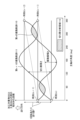
- FIG. 3 is an explanatory diagram of the mechanism by which chip fragmentation occurs during vibration cutting performed by the machine tool 3.
- the horizontal axis in FIG. 3 indicates the rotation angle of the main shaft 300. The rotation angle goes around once every 360 degrees and returns to 0 degrees.
- the vertical axis in FIG. 3 indicates the relative distance between the tool 304 and the workpiece 303 in the direction along the tool path. When vibration is not applied, each rotation moves by the feed amount F per rotation specified in the tool path.
- the tool 304 is vibrated while being sent in the Z-axis direction, so the relative distance between the workpiece 303 and the tool 304 during one rotation of the main shaft 300 is such that the vibration is sinusoidal. It becomes a trajectory. This trajectory is called a vibration trajectory.
- the example in FIG. 3 shows a vibration trajectory when the drive shaft 301 in the Z-axis direction is vibrated 1.5 times during one rotation of the main shaft 300.
- the vibration locus is determined by the spindle rotation speed S (r/min), the feed rate per rotation F (mm/r) which is the feed rate of the tool 304 to the workpiece 303 per spindle rotation, and the vibration amplitude A of the tool 304 ( mm) and the angular frequency of vibration of the tool 304 ⁇ v (rad/s).
- FIG. 3 shows an n-th vibration trajectory 110, which is the vibration trajectory during the n-th spindle rotation, and an (n+1)-th vibration trajectory 111, which is the vibration trajectory during the n+1-th spindle rotation.
- the n-th vibration trajectory 110 is a vibration trajectory between time t(n), which is the time when the main shaft 300 passes through 0 degrees, and time t(n+1), which is the time after the main shaft has made one revolution.
- the (n+1)th vibration locus 111 is a vibration locus between time t(n+1) and time t(n+2), which is the time after the main shaft has made one revolution.
- the time t(n) here may be an arbitrary reference time, for example, the reference time may be the time at which machining is started.
- the distance between the n-th vibration locus 110 and the (n+1)-th vibration locus 111 at the same main axis angle is the thickness of the chips, which is the chip thickness.
- the chip separation region 112, which is a hatched region in FIG. 3, is a region where the n-th vibration trajectory 110 and the (n+1)-th vibration trajectory 111 overlap. In this region, material has already been removed from the surface of the workpiece 303 at the n-th vibration locus 110, and therefore, at the n+1-th vibration locus 111, air cut occurs without material being removed. In the area sandwiched between the air cut areas, the chips are not continuous, so the chips are divided. Therefore, in order to generate chip fragmentation, it is desirable to set the driving conditions for vibration cutting so that an air cut region is generated.
- the spindle rotation speed S (r/min) and the feed rate per rotation F (mm/r) are given as machining conditions that should be determined in turning regardless of whether or not vibration cutting is performed, and the tool
- the vibration amplitude A (mm) of the relative vibration between 304 and the workpiece 303 and the angular frequency ⁇ v (rad/s) of the vibration are given, the angular frequency ⁇ s (rad/s) of the rotation of the main shaft is given. is determined by the following formula (1).
- Formula (4) is derived from Formula (2) and Formula (3).
- ⁇ is the phase difference between the n-th vibration locus 110 and the (n+1)-th vibration locus 111.
- the n-th vibration locus 110 and the (n+1)-th vibration locus 111 touch at a point.
- the conditions under which chip fragmentation occurs can be expressed by a mathematical formula. As long as the conditions shown in formulas (4) and (5) can be satisfied, processing conditions and vibration conditions can be freely selected. On the other hand, if a driving condition is set that does not satisfy either Equation (4) or Equation (5), vibration cutting will not occur because chips will not be separated.
- the operator uses the search condition input section 100 to input the spindle rotation speed and the feed rate per blade as the standard machining conditions 11.
- the standard machining conditions 11 may be information expressed in any format as long as the angular frequency of the spindle rotation and the feed amount per rotation can be uniquely determined.
- the standard machining conditions 11 may include information expressing the Z-axis feed rate in feed amount per minute (mm/min).
- the search condition input section 100 calculates the feed rate per blade from the input feed amount per minute, and sends the calculation result to the condition search section 102.
- the reference machining conditions 11 may directly include the angular frequency of the spindle rotation instead of the spindle rotation speed.
- the operator uses the search condition input unit 100 to input the vibration frequency and vibration amplitude, which are the reference vibration conditions 12, as search conditions. Furthermore, the operator uses the search condition input unit 100 to input the vibration condition search range 14, which is the search range of vibration conditions, as a search condition.
- the vibration condition search range 14 includes a vibration frequency search range and a vibration amplitude search range. Note that if the vibration frequency and vibration amplitude can be uniquely determined for the standard vibration conditions 12 and the vibration condition search range 14, the standard vibration conditions 12 and the vibration condition search range 14 can be information expressed in any format. There may be.
- the reference vibration condition 12 and the vibration condition search range 14 may include a value of vibration frequency as the number of vibrations per rotation of the spindle, or a value of vibration amplitude as a ratio to the feed rate per blade.
- search condition input section 100 converts the input values into vibration frequency and vibration amplitude and outputs them to condition search section 102.
- the condition search unit 102 determines execution drive conditions, which are drive conditions to be used when actually performing machining.
- the execution drive conditions determined by the condition search unit 102 include execution machining conditions 15, which are machining conditions used when actually machining, and vibration conditions used when actually machining.
- a certain execution vibration condition 16 is included.
- FIG. 4 is a flowchart for explaining the operation of the condition search unit 102 shown in FIG. 1.
- the condition search unit 102 first sets the reference machining conditions 11 and reference vibration conditions 12 included in the search conditions output by the search condition input unit 100 (step S1).
- the condition search unit 102 determines whether the set machining conditions and vibration conditions satisfy the dividing conditions (step S2).
- step S2 determines whether the vibration amplitude is adjustable (step S3), and if the vibration amplitude is adjustable (step S3: Yes). ), the vibration amplitude is changed within the vibration amplitude search range (step S4). After step S4, the condition search unit 102 returns to the process of step S2. In this case, the condition search unit 102 repeats the processes from step S2 to step S4 of changing the vibration amplitude and determining whether or not the dividing condition is satisfied, as long as the vibration amplitude can be adjusted, until the dividing condition is satisfied. It turns out.
- the condition search unit 102 starts from the lower limit value of the vibration amplitude search range and adds a constant value each time the vibration amplitude search range is changed, thereby increasing the value of the vibration amplitude from the lower limit value to the upper limit value of the vibration amplitude search range. You can explore. In this case, in step S3, if the value of the vibration amplitude after the change has not reached the upper limit value, the condition search unit 102 determines that the vibration amplitude can be adjusted, and the value of the vibration amplitude after the change is the upper limit value. , it can be determined that the vibration amplitude is not adjustable.
- step S3 If the vibration amplitude is not adjustable (step S3: No), the condition search unit 102 changes the vibration frequency within the vibration frequency search range (step S5). At this time, the condition search unit 102 sets the value of the vibration amplitude to the lower limit value of the vibration amplitude search range, and returns to the process of step S2.
- step S6 When the dividing conditions are satisfied (step S2: Yes), the condition search unit 102 outputs the set machining conditions and vibration conditions as execution drive conditions (step S6).
- the condition search unit 102 outputs the standard machining conditions 11 and the standard vibration conditions 12 as execution drive conditions, and If the reference vibration condition 12 does not satisfy the dividing condition, first, a vibration condition that satisfies the dividing condition is searched for while changing the vibration amplitude by a constant value from the lower limit value to the upper limit value of the vibration amplitude search range. Even if the vibration amplitude reaches the upper limit value, if a vibration condition that satisfies the dividing condition is not found, then the condition search unit 102 changes the vibration frequency to the lower limit value, changes the vibration amplitude to the lower limit value, and then increases the vibration amplitude.
- the condition search unit 102 finds a combination of vibration amplitude and vibration frequency that satisfies the dividing condition within the search range. You can explore.
- the numerical control device 1a performs vibration cutting in which the shaft that changes the relative position of the workpiece 303 and the tool 304 is vibrated during cutting to break up chips.
- a drive condition determination device that determines drive conditions of a machine tool 3 to perform processing, the vibration conditions that define the vibration frequency and vibration amplitude of at least one of the drive shaft 301 and the main shaft 300 to be vibrated; and a search range set for at least one drive condition of the control parameters, which are parameters that determine the control characteristics of the axis, and a reference machining, which is the standard machining conditions determined regardless of the presence or absence of vibration cutting.
- the apparatus includes a condition search unit 102 that determines execution drive conditions that are drive conditions used when performing vibration cutting. Therefore, even if the operator is unable to appropriately determine the drive conditions for the machine tool 3 when performing vibration cutting, the drive conditions are searched within the set search range and chip fragmentation occurs. Since it is possible to automatically determine the driving conditions, it is possible to increase the possibility that chips will break up when the machine tool performs vibration cutting.
- FIG. 5 is a diagram showing the functional configuration of the information processing device 1b according to the second embodiment.
- the information processing device 1b is an example of a drive condition determining device that determines the drive conditions of the machine tool 3.
- components similar to those in Embodiment 1 will be denoted by the same reference numerals and detailed explanations will be omitted, and portions that are different from Embodiment 1 will be mainly described.
- the information processing device 1b is a device that is installed inside a computer and determines machining conditions and vibration conditions that are drive conditions when performing vibration cutting with the machine tool 3.
- the information processing device 1b inputs the standard machining conditions 11, the standard vibration conditions 12, and the vibration condition search range 14, and outputs the execution machining conditions 15 and the execution vibration conditions 16 to the machining program generation device 103.
- the machining program generation device 103 is CAM (Computer Aided Manufacturing) software that generates a machining program 10 for the machine tool 3 called an EIA program or G code from machining path generation information.
- the machining program generation device 103 generates the spindle rotation speed, feed amount per tooth, vibration frequency, and vibration amplitude for a machining program that describes a machining path to be machined under the standard machining conditions 11 output by CAM software or the like. It may be software that additionally edits information corresponding to a command and outputs the edited machining program 10.
- the information processing device 1b includes a search condition input section 100 and a condition search section 102b.
- the condition search unit 102b determines execution drive conditions using a machine model 105 that simulates the characteristics of the machine tool 3.
- the drive shaft 301 vibrates with the same vibration amplitude as the vibration amplitude commanded to the drive shaft servo control unit 202.
- the amplitude of the relative vibration between the tool 304 and the workpiece 303 is , may differ from the commanded vibration amplitude. In such cases, even if the commanded vibration amplitude and vibration frequency satisfy the chip breaking conditions, the vibration amplitude generated during actual machining is different from the command value, so chip breaking may not occur. be.
- the condition search unit 102b of the information processing device 1b searches for vibration conditions using a machine model 105 that simulates the mechanical characteristics of the machine tool 3, taking into account the difference between the command value and the actual value of vibration amplitude. . Specifically, the condition search unit 102b uses the machine model 105 to estimate the actual vibration amplitude at the tip position of the tool 304 with respect to the commanded vibration amplitude, and the value of the estimated vibration amplitude satisfies the cutting condition. Search for vibration conditions that satisfy.
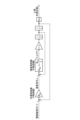
- FIG. 6 is a diagram showing an example of the machine model 105 shown in FIG.
- FIG. 6 shows a mechanical model 105 that simulates the mechanical characteristics of the drive shaft servo control unit 202 and the drive shaft 301 in the frequency domain.
- the drive shaft servo control unit 202 has a controller that controls the position x of the tip of the tool 304 in response to the drive shaft command 17r, and has a cascade type control structure that has a speed control loop inside the position control loop.
- the position control includes a P (Proportion) controller which is a position controller that calculates the speed command vr by multiplying the difference in the tool tip position x with respect to the drive axis command 17r by the position loop gain K p .
- P Proportion
- the speed controller adds the result of multiplying the difference between the speed command vr and the tool tip speed v by the speed loop gain Kvp and the result of multiplying and integrating the speed integral gain Kvi , and controls the servo motor 305.
- It has a PI (Proportion Integral) controller which is a speed controller that calculates the torque Tr output by the motor.
- this machine model 105 calculates the tool tip speed v by multiplying and integrating the torque command by J that simulates the total moment of inertia of the drive shaft 301, and by integrating the tool tip speed v, the tool tip Calculate the position x.
- s is a Laplace operator, and "1/s" represents an integral operation.
- the machine model 105 described above is just an example, and any model may be used as long as it can calculate the response of the tool tip position to the position command.
- a controller other than the P controller or PI controller may be used, or the characteristics of the drive shaft 301 may be expressed by a transfer function instead of the total moment of inertia.
- a current control loop for calculating the servo motor current 22 output from the servo motor 305 may be provided inside the speed control loop. At this time, the torque Tr is calculated by multiplying the motor current by a torque constant for calculating the motor torque from the motor current.
- a model described as a discrete system using difference equations may be used as the machine model 105.
- FIG. 7 is a flowchart for explaining a first example of the operation of the condition search unit 102b shown in FIG. 5.
- the processing from step S1 to step S6 is the same as that in FIG. In FIG. 7, before determining whether the dividing condition is satisfied in step S2, the condition search unit 102b estimates the vibration amplitude using the mechanical model 105 (step S7).
- the condition search unit 102b uses the machine model 105 to calculate the actual vibration amplitude between the tool 304 and the workpiece 303 from the set vibration amplitude.
- a method of calculating the vibration amplitude using the model expressed by the above equation (7) will be described.
- Equation (8) the response at a certain frequency ⁇ can be calculated by substituting j ⁇ for s in Equation (7).
- j is an imaginary unit.
- the actual vibration output between the tool 304 and the workpiece 303 can be calculated as a mathematical formula, so for the set vibration amplitude A, The actual vibration amplitude A' between the tool 304 and the workpiece 303 can be calculated using the set vibration frequency ⁇ v and Equation (9).
- the input vibration has a single frequency ⁇
- the input vibration waveform may be a rectangular wave, a triangular wave, etc.
- a rectangular wave-like vibration command can be obtained using a Fourier series at a frequency (2 ⁇ -1) It is known that it can be described as the sum of simple harmonic motions of ⁇ .
- Equation (10) and Equation (9) it is possible to calculate the amplitude for a rectangular wave vibration command.
- the amplitude ratio may be calculated by approximating it as a function of only the first-order frequency component.
- the amplitude ratio can be similarly calculated for commands simulating triangular waves and other periodic vibrations.
- step S2 of FIG. 7 the condition search unit 102b uses the vibration amplitude A' calculated in step S7 instead of the set vibration amplitude A to determine whether the dividing condition is satisfied.
- FIG. 8 is a flowchart for explaining a second example of the operation of the condition search unit 102b shown in FIG.
- the actual vibration amplitude A' is calculated before determining whether the dividing condition is satisfied, but in the second example shown in FIG.
- the vibration amplitude is corrected based on the mechanical model 105 before outputting it as an execution drive condition (step S8).
- the condition search unit 102b searches for the vibration amplitude A and the vibration frequency ⁇ v that satisfy the dividing condition, so that the vibration amplitude between the tool 304 and the workpiece 303 matches A. By multiplying the vibration amplitude A by the reciprocal of formula (9), the corrected vibration amplitude A'' is calculated. In step S6, the condition search unit 102b outputs the execution drive condition including the corrected vibration amplitude A''.
- the actual vibration amplitude value was calculated from the vibration amplitude command value using a mathematical formula, but the method for estimating the actual vibration amplitude value is not limited to the above example.
- the condition search unit 102b experimentally determines the actual vibration amplitude value using a mathematical formula, data table, etc. that approximates the actual vibration amplitude value experimentally derived for the vibration amplitude command value. may be estimated.
- the condition search unit 102b uses a discrete system model described by a difference equation instead of formula (7), and performs conversion from a discrete system model to a continuous system model called bilinear transformation or Tustin transformation. The amplitude ratio may be calculated by converting into a continuous system using the formula.
- condition search unit 102b may calculate the response waveform from the model through numerical simulation, and calculate the amplitude ratio from the response waveform obtained through the simulation.
- FIG. 9 is a diagram showing the relationship between the response amplitude and the vibration amplitude command value, which is experimentally derived.
- FIG. 9 is a diagram called a Bode diagram, in which a sine wave signal or random noise with a continuously changing frequency is commanded to a servo motor, and the vibration between the tool 304 and the workpiece 303 at that time is accelerated. It can be obtained by measuring using a sensor, displacement sensor, etc. In this figure, the ratio of output amplitude to input amplitude is calculated at each frequency.
- 0 dB means that the input amplitude and output amplitude match; if the gain is larger than 0 dB, the output amplitude will be larger than the input amplitude, and if the gain is smaller than 0 dB, the output amplitude will be larger than the input amplitude. This means that the amplitude is smaller.
- the actual vibration amplitude relative to the input vibration amplitude command value can be determined without using numerical calculations. For example, the characteristics of the Bode diagram may be approximated by a mathematical formula, or table data may be used in the machine model 105 to calculate the actual value of the vibration amplitude.
- the condition search unit 102b uses the mechanical model 105 to estimate the actual vibration amplitude at the tip position of the tool 304 from the drive axis command for the axis. Based on the obtained vibration amplitude, a drive condition that satisfies the dividing condition is searched. Since the estimated value of the actual vibration amplitude is used instead of the command value of the vibration amplitude to determine whether or not the breaking condition is satisfied, the possibility of chip breakage occurring when the machine tool 3 performs vibration cutting can be more reliably determined. It becomes possible to increase the
- FIG. 10 is a diagram showing the functional configuration of the information processing device 1c according to the third embodiment.
- the information processing device 1c is an example of a driving condition determining device.
- the information processing device 1c includes a search condition input section 100c and a condition search section 102c.
- the search condition input unit 100c acquires the standard machining condition 11, the standard vibration condition 12, the machining condition search range 13, and the vibration condition search range 14 as search conditions.
- the condition search unit 102c uses the machine model 105c and the evaluation function 106 to search for drive conditions.
- FIG. 11 is a diagram showing an example of the machine model 105c shown in FIG. 10.
- the difference between the machine model 105c and the machine model 105 of the second embodiment is that the machine model 105c has a machine end transfer function model Gm(s).
- Gm machine end transfer function model
- control is performed so that the position detected by the detector matches the commanded position.
- the object whose vibration amplitude should truly be controlled is the relative vibration between the tool 304 and the workpiece 303, but relative displacement between the tool 304 and the workpiece 303 is It is difficult to install a detector to detect this. Therefore, feedback control is performed using a detector attached to the servo motor 305, and the actual relative vibration between the tool 304 and the workpiece 303 is estimated using the machine end transfer function model Gm(s).
- the machine end model is measured by, for example, installing an acceleration sensor on each of the tool 304 and the workpiece 303.
- the transfer function may be identified by curve fitting by differentiating the detector signal twice when the motor is driven, drawing a Bode diagram that inputs the acceleration signal and outputs the relative acceleration, or identifies the transfer function using a finite element
- a transfer function calculated from a model of the structure of the machine tool 3 by the Finite Element Method (FEM) may be used, or a state space model output from an element composition matrix of the FEM model may be used.
- FEM Finite Element Method
- FIG. 12 is a flowchart for explaining the operation of the condition search unit 102c shown in FIG. 10.
- the condition search unit 102c first sets the standard machining conditions 11 and the standard vibration conditions 12 (step S1). Subsequently, the condition search unit 102c estimates the actual vibration amplitude using the mechanical model 105c (step S7). The condition search unit 102c determines whether the set machining conditions and vibration conditions satisfy the dividing conditions (step S2). At this time, the condition search unit 102c uses the actual vibration amplitude estimated in step S7 as the vibration amplitude of the vibration condition.
- step S3 determines whether the vibration amplitude can be adjusted. If the vibration amplitude is adjustable (step S3: Yes), the condition search unit 102c changes the vibration amplitude within the vibration amplitude search range (step S4), and returns to the process of step S7.
- step S3 determines whether the vibration amplitude is adjustable (step S9). If the vibration frequency is adjustable (step S9: Yes), the condition search unit 102c changes the vibration frequency within the vibration frequency search range (step S5), and returns to the process of step S7.
- step S9 determines whether the vibration frequency is adjustable (step S10). If the spindle rotation speed is adjustable (step S10: Yes), the condition search unit 102c changes the spindle rotation speed within the rotation speed search range (step S11), and returns to the process of step S7.
- step S10 determines whether the feed amount is adjustable (step S12). If the feed amount is adjustable (step S12: Yes), the condition search unit 102c changes the feed amount within the feed amount search range (step S13), and returns to the process of step S7.
- step S12 If the feed amount cannot be adjusted (step S12: No), a search failure is output (step S14) and the process ends.
- step S2 If the dividing condition is satisfied (step S2: Yes), the condition search unit 102c next determines whether the set machining conditions and vibration conditions satisfy the first evaluation function (step S15). If the first evaluation function is not satisfied (step S15: No), the condition search unit 102c proceeds to the process of step S3. If the first evaluation function is satisfied (step S15: Yes), the condition search unit 102c outputs the set machining conditions and vibration conditions as execution drive conditions (step S6).
- the first evaluation function is a function for evaluating the searched machining conditions and vibration conditions. Even if the searched machining conditions and vibration conditions satisfy the chip breaking conditions, if machining takes too long or the load on the machine tool 3 is too large, machining may be performed using such machining conditions and vibration conditions. It is not recommended to do so. Therefore, the information processing device 1c uses an evaluation function to determine whether the searched combination of processing conditions and vibration conditions is appropriate.
- the first evaluation function is a linear sum of any one or more of the following: electrical energy required for vibration, vibration acceleration, machining time, cutting volume, maximum machining load, amount of machine wear, and cumulative vibration cutting time. It is expressed as For example, the first evaluation function can be set to "V>100" using the cutting volume V (mm 3 /min).
- the cutting volume V can be expressed by the following formula (11) using the spindle rotation speed S, the feed rate per tooth F, the radial depth of cut h, and the diameter R (mm) of the workpiece 303. .
- the first evaluation function may simply be that the spindle rotation speed is greater than or equal to the lower limit value, or may be that the feed amount is greater than or equal to the lower limit value. Alternatively, the first evaluation function may be a combination of these.
- each condition in the step of changing each condition within the search range, each condition can be changed by a constant value from the lower limit value to the upper limit value of the search range.
- it in the step of determining whether each condition is adjustable, it can be determined whether each condition is adjustable based on whether the value after the change exceeds the upper limit.
- step S5 the vibration amplitude is changed to the lower limit value of the vibration amplitude search range
- step S11 the vibration amplitude is changed to the lower limit value of the vibration amplitude search range, and the vibration frequency is changed to the lower limit value of the vibration frequency search range.
- step S13 the vibration amplitude is changed to the lower limit value of the vibration amplitude search range, the vibration frequency is changed to the lower limit value of the vibration frequency search range, and the spindle rotation speed is changed to the lower limit value of the rotation speed search range. change.
- the search may fail. If a driving condition that satisfies both the dividing condition and the first evaluation function is not found, the user is notified of the search failure in step S14. In this case, the user can reset the search range and redo the search.
- the search is terminated when one driving condition that satisfies both the dividing condition and the first evaluation function is found, but within all search ranges, candidates for execution driving conditions that satisfy the dividing condition are found.
- the execution driving condition may be determined based on the first evaluation function by searching for a plurality of candidates. In this case, when a plurality of candidates exist, it becomes possible to use conditions suitable for processing among the plurality of candidates.
- the condition search unit 102c searches for execution drive condition candidates that satisfy the dividing condition, and performs cutting using the searched candidates. Based on the first evaluation function for evaluation, it can be determined whether or not the searched candidate is to be the execution driving condition. As a result, even if the cutting conditions are met, conditions for which the evaluation of the cutting process is low, such as conditions that take too much time or place too much load on the machine tool 3, can be prevented from being set as the execution driving conditions. It becomes possible.
- the first evaluation function is based on any one or more of the energy required to generate vibration, vibration acceleration, machining time, cutting volume, maximum machining load, amount of machine wear, and cumulative vibration cutting time. It can be a function expressed as a linear sum of parameters. This makes it possible to evaluate the cutting process based on these parameters.
- the energy required to generate vibration is determined by "1/2 MA 2 ⁇ v 2 " when expressed in vibration energy, where M is the mass of the shaft that performs vibration cutting.
- a value obtained by converting the above-mentioned vibrational energy into electrical energy may be used as the energy required to generate the vibration.
- the value obtained by dividing the vibrational energy by a coefficient representing the efficiency of converting electrical energy into vibrational energy can be determined as the energy required to generate the vibration.
- machining time calculate the shaft movement amount SF per minute based on the feed rate F per revolution and the spindle rotation speed S, and calculate the total machining distance L for vibration cutting by the shaft movement amount per minute. By dividing by SF, the machining time "L/SF" can be calculated.
- the maximum machining load is calculated as “K c AF/1000” using the specific cutting force K c determined from the material properties of the workpiece 303. Further, the amount of machine wear is calculated by accumulating the vibration cutting time up to now and multiplying the cumulative vibration cutting time by a coefficient determined experimentally.
- the evaluation function Z is divided into two evaluation functions with coefficients P 1 and P 2 , as expressed by the following formula (12). It can be found as a linear sum of However, the coefficients P 1 and P 2 can take any predetermined real numbers.
- a search failure is notified, so the user can change the search condition.
- the driving conditions can be searched again.
- FIG. 13 is a diagram showing a functional configuration of an information processing device 1c-2 according to a modification of the third embodiment. In comparison with the information processing device 1c, the information processing device 1c-2 shown in FIG. The difference is that it has -2.
- the AI model 107 is a trained model that outputs the actual vibration amplitude at the tip position of the tool 304 when the command value of vibration amplitude, spindle rotation speed, feed rate per tooth, and vibration frequency are input.
- the AI model 107 may be, for example, a model trained by artificial intelligence using an algorithm such as a neural network, reinforcement learning, or Q-learning.
- FIG. 14 is a diagram showing the functional configuration of the numerical control device 1d according to the fourth embodiment.
- the numerical control device 1d includes a search condition input section 100, a machining program input section 101, a condition search section 102d, and a command value generation section 104.
- the numerical control device 1d is different from the numerical control device 1a in that the inputs to the search condition input section 100 are the standard machining conditions 11, the machining condition search range 13, and the vibration condition search range 14, and the machine model 105 and evaluation function 106 as inputs. Note that in the numerical control device 1d, the reference vibration condition is not included in the input to the search condition input section 100. Therefore, at the start of the search, the search is started from the lower limit of the vibration condition search range, the upper limit of the vibration condition search range, the intermediate value of the vibration condition search range, or the initial search conditions set in advance using parameters, etc. It turns out.
- FIG. 15 is a flowchart for explaining the operation of the condition search unit 102d shown in FIG. 14. Here, differences from the condition search unit 102c of the third embodiment shown in FIG. 12 will be explained.
- the condition search unit 102d further determines whether or not the second evaluation function is satisfied (step S17).
- step S17: Yes If the second evaluation function is satisfied (step S17: Yes), the condition search unit 102d returns to step S3 and continues searching for conditions without adopting the set conditions. If the second evaluation function is not satisfied (step S17: No), the condition search unit 102d proceeds to step S6.
- step S12 the condition search unit 102 sets drive conditions that include the standard machining condition 11 and does not perform vibration cutting (step S16), and then proceeds to step S6. move on.
- Step S17 in FIG. 15 functions as a safety device, and when "an abnormality occurs when vibration cutting is performed using the set machining conditions and vibration conditions", the step S17 is set to "satisfy the second evaluation function".
- the second evaluation function is set.
- the second evaluation function is It is filled.
- Examples of electrical equipment equipped on the machine tool 3 include a numerical control device, a drive device called a drive unit, a motor, an electromagnetic switch, and a relay.
- An example of the second evaluation function is a function using vibration energy H, power consumption, and vibration amplitude. Further, the same function may be used as the first evaluation function and the second evaluation function, and different threshold values may be provided.
- the first evaluation function assumes that the machining time is 3 minutes or more
- the second evaluation function assumes that the machining time is 10 minutes or more. In this case, if the machining time is less than 3 minutes, the first evaluation function is not satisfied, and if the machining time is 10 minutes or more, the second evaluation function is satisfied, so the set drive condition is not selected. Therefore, only when the machining condition is 3 minutes or more and less than 10 minutes is output as the execution drive condition.
- an evaluation function setting section may be provided in which the user sets arbitrary conditions as the first evaluation function and the second evaluation function.
- the second evaluation function also includes electrical energy required to generate vibration, vibration acceleration, machining time, cutting volume, maximum machining load, amount of machine wear, and cumulative vibration cutting time. It can be a function expressed by a linear sum of any one or more of the following.
- the first evaluation function is preferably a function that can determine that vibration cutting using the driving conditions is suitable when the first evaluation function is satisfied, and the second evaluation function is , when the second evaluation function is satisfied, the function can be used to determine that it is desirable not to adopt the drive condition as the execution drive condition, such as when an abnormality occurs in vibration cutting using the drive condition. desirable.
- the machining load and the amount of wear are predicted by a machining simulation using the machine model 105. Further, the cumulative vibration cutting time is set in a memory that records the total time of vibration cutting performed so far.
- an evaluation function using the number of chips that can be separated by vibration cutting in one rotation can be considered. For example, if chips are separated too many times during one rotation, the servo motor 305 is loaded and generates heat.
- the number of times the chips are divided per rotation as an evaluation function, it is possible to search for driving conditions so as to obtain an appropriate number of times the chips are divided.
- condition search unit 102d of the numerical control device 1d selects candidates for execution drive conditions that satisfy the dividing condition, and determines whether or not an abnormality will occur in the cutting process using the candidates. If it is evaluated that an abnormality occurs in the cutting process using the candidate, the candidate is not set as the execution driving condition. Thereby, even if the cutting conditions are met, it is possible to prevent driving conditions from being selected that would cause an abnormality in the cutting process.
- the condition search unit 102d determines a drive condition that includes standard machining condition 11 and does not perform vibration cutting as an execution drive condition. be able to. In this case, if no driving conditions are found that would result in no abnormalities using the second evaluation function, priority is given to performing cutting that does not cause abnormalities without performing vibration cutting. can do.
- FIG. 16 is a diagram showing the functional configuration of the information processing device 1e according to the fifth embodiment.
- the information processing device 1e has a condition search unit 102e in place of the condition search unit 102c, in which the information input to the search condition input unit 100 is a reference processing condition 11, a vibration condition search range 14, and a control parameter search range 19. This differs from the third embodiment in this point.
- the inputs to the information processing device 1e are the standard machining conditions 11, the vibration condition search range 14, and the control parameter change range 19, and the output from the information processing device 1e is the execution machining conditions 15, the execution vibration conditions 16, and the control parameters. It is 24.
- the reference vibration condition is not included in the input to the search condition input section 100. Therefore, at the start of the search, the search is started from the lower limit of the vibration condition search range, the upper limit of the vibration condition search range, the intermediate value of the vibration condition search range, or the initial search conditions set in advance using parameters, etc. It turns out.
- FIG. 17 is a flowchart for explaining the operation of the condition search unit 102e shown in FIG. 16.
- the condition search unit 102e sets the standard processing conditions 11 (step S1e).
- the condition search unit 102e determines whether the set condition satisfies the dividing condition (step S2). If the dividing condition is not satisfied (step S2: No), the condition search unit 102e determines whether the vibration amplitude can be adjusted (step S3). If the vibration amplitude is adjustable (step S3: Yes), the condition search unit 102e changes the vibration amplitude within the vibration amplitude search range (step S4), and returns to the process of step S2.
- step S3 determines whether the vibration amplitude is adjustable (step S9). If the vibration frequency is adjustable (step S9: Yes), the condition search unit 102e changes the vibration frequency within the vibration frequency search range (step S5), and returns to the process of step S2.
- step S9 determines whether the vibration frequency is adjustable (step S9: No). If the vibration frequency is not adjustable (step S9: No), the condition search unit 102e determines whether the control parameters are adjustable (step S18). If the control parameter is adjustable (step S18: Yes), the condition search unit 102e changes the control parameter within the control parameter adjustment range (step S19), and returns to the process of step S2.
- step S18 If the control parameters cannot be adjusted (step S18: No), the condition search unit 102e sets drive conditions that include the reference machining conditions 11 and does not perform vibration cutting (step S16), and adjusts the set machining conditions, vibration conditions, and The control parameters are output as execution driving conditions (step S6e).
- step S2 If the dividing condition is satisfied (step S2: Yes), the condition search unit 102e corrects the vibration amplitude based on the mechanical model 105 (step S8).
- the condition search unit 102e determines whether the set drive condition satisfies the second evaluation function (step S17). If the second evaluation function is satisfied (step S17: Yes), the condition search unit 102e proceeds to the process of step S3; if the second evaluation function is not satisfied (step S17: No), the condition search unit 102e The process advances to step S6e.
- control parameters are searched in addition to vibration conditions.
- the control parameters are, for example, a position loop gain K p , a velocity loop gain K vp , and a velocity integral gain K vi .
- the control parameter is a parameter that determines the control characteristics of the drive shaft 301, and as shown in equation (10), the control parameter affects the calculation of the vibration amplitude. For this reason, even under the same vibration conditions, whether or not chips will break apart will vary depending on the magnitude of the control parameter.
- the control parameter to be changed may be only the position loop gain Kp, or both the position loop gain Kp and the velocity loop gain Kvp .
- the parameters to be changed may be determined in advance, or may be arbitrarily selected by the user for each process. Furthermore, when using a model other than the illustrated mechanical model 105, control parameters that affect vibration amplitude can be searched for in the model used. By searching for control parameters, it is possible to increase the possibility of searching for drive conditions that can break up chips.
- phase margin is the phase margin from -180 degrees when the gain is 0 dB in the control system, and generally, if a phase margin of 30 degrees or more is secured, the control system will be stabilized. Further, the gain margin is the gain margin from 0 dB when the phase is -180 degrees.
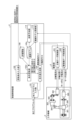
- FIG. 18 is a diagram showing the functional configuration of the numerical control device 1f according to the sixth embodiment.
- the numerical control device 1f has a mechanical model updating unit that updates the mechanical model 105c based on the measured value of the vibration amplitude output by the acceleration sensor 306 that measures the vibration amplitude. 113, and a failure prediction unit 114 that predicts a failure of the machine tool 3 based on aging of the machine model 105c.
- the mechanical model 105c is the same as the mechanical model 105c shown in FIG. 11.
- the reference vibration condition is not included in the input to the search condition input section 100. Therefore, at the start of the search, the search is started from the lower limit of the vibration condition search range, the upper limit of the vibration condition search range, the intermediate value of the vibration condition search range, or the initial search conditions set in advance using parameters, etc. It turns out.
- the vibration characteristics of the machine tool 3 gradually change over time. For example, vibrations in mechanical structures may increase due to loosening of fasteners, fatigue failure of structural members, loss of preload in bearings or ball screws, and the like. Additionally, the load on the motor may increase due to increased friction. If vibration cutting is continued in this state, the machine tool 3 may break down. Therefore, the numerical control device 1f has a function of monitoring the secular change of the machine tool 3 from the difference between the vibration amplitude predicted by calculation and the actual vibration amplitude, and predicting a failure before it actually occurs. , the machine tool 3 can be repaired at an appropriate time.
- the acceleration sensor 306 is installed on the drive shaft 301. In FIG. 18, the acceleration sensor 306 is attached to the nut of the ball screw, but it may be attached, for example, inside the tool holder of the tool 304, or to the turret on which the tool of a lathe is attached.
- the acceleration sensor 306 measures the vibration level during vibration cutting and transmits it to the machine model update unit 113.
- the machine model updating unit 113 compares the calculated value of the vibration amplitude calculated from the execution machining conditions 15 and the execution vibration conditions 16 with the actual measured value of the vibration amplitude.
- Gm(s) that simulates the characteristics of the drive shaft 301 in the mechanical model 105c is changed. This makes it possible to accurately estimate the vibration amplitude even if the mechanical properties change.
- the failure prediction unit 114 monitors the change history of the machine model 105c. If the amount of change in the machine model 105c exceeds a predetermined threshold, it is determined that the aging of the machine tool 3 has exceeded the allowable value and a failure has occurred, and a warning is output to the user.
- the method of outputting the warning is not particularly limited, and the warning may be issued by screen display or by audio output. However, the failure prediction unit 114 may make a determination based on whether the current amount of change in the machine model 105c exceeds a threshold, or may predict that the threshold will be exceeded in the future for a certain period of time and output a warning. .
- the numerical control device 1f can handle the case where the mechanical characteristics change by changing the control parameters in accordance with the change in the machine model 105c due to aging of the machine tool 3. This has the effect that the vibration amplitude can be accurately estimated even when the vibration amplitude is low. Furthermore, by detecting the occurrence of a failure or a sign of the occurrence of a failure based on the amount of change in the machine model 105c, it is possible to make a repair or repair plan in advance, and prevent production from stopping due to a sudden failure. This makes it possible to avoid such situations.
- FIG. 19 is a diagram showing the functional configuration of an information processing device 1g according to the seventh embodiment.
- the information processing device 1g includes a search condition input section 100, a condition search section 102g, and a learned model storage section 120.
- the condition search unit 102g includes a learning data acquisition unit 40 and a model generation unit 41.
- the learning data acquisition unit 40 receives the standard machining conditions 11 and the standard vibration conditions 12 from the search condition input unit 100, and also performs vibration cutting on the control parameters 24, tool information 30, workpiece information 31, and motion information 32 for each axis. Obtain as learning data.
- the tool information 30 includes information indicating the tool material and tool shape.
- the workpiece information 31 includes information indicating the material of the workpiece.
- the motion information 32 for each axis includes information indicating the feed rate of each axis and the acceleration of each axis.
- the model generation unit 41 uses the machine model 105, the machined surface quality determination model 42, and the chip division determination model 43 to satisfy the dividing condition based on the vibration cutting learning data acquired by the learning data acquisition unit 40.
- the execution drive conditions the execution drive conditions that give the best cutting quality are learned.
- the model generation unit 41 receives the standard machining conditions 11, the standard vibration conditions 12, the control parameters 24, the motion information 32 of each axis, the workpiece information 31, and the tool information 30, and generates the dividing conditions.
- a condition/control parameter search model 48 that outputs a combination of execution machining conditions 15, execution vibration conditions 16, and control parameters 24 such that the machining quality of cutting satisfies the standards is output as a learning result.
- the operation information 32 of each axis is information indicating the operation position of the motor of each axis of the machine tool 3, and the model generation unit 41 generates information about the machine tool 3 from the operation information 32 of each axis and the control parameters 24.
- the machine model 105 is used to obtain information indicating the movement of the mechanical structure attached to each axis. That is, the machine model 105 receives the operation information 32 and control parameters 24 of each axis as input, and outputs information indicating the movement of the mechanical structure attached to each axis of the machine tool 3.
- the model generation unit 41 uses the chip division determination model 43 in order to determine whether or not division of chips occurs, that is, to determine whether or not division conditions are satisfied.
- the chip division determination model 43 receives the output of the machine model 105, the standard machining conditions 11, the standard vibration conditions 12, and the control parameters 24, and outputs a determination result as to whether or not chip division occurs. Furthermore, the model generation unit 41 uses the machined surface quality determination model 42 to determine whether the machining quality of cutting using the driving conditions determined to cause chip fragmentation satisfies the standard. The machined surface quality determination model 42 determines whether the result of machining the workpiece 303 is good or bad based on the motion information 32 of each axis. The machined surface quality determination model 42 receives as input the output of the machine model 105, the drive conditions determined to satisfy the dividing condition using the chip division determination model 43, the workpiece information 31, and the tool information 30.
- Processing quality is determined based on the smoothness of the machined surface.
- the machined surface quality determination model 42 can evaluate the machining quality using the variation or maximum error amount of each tool path with respect to the average line or average surface calculated based on the arithmetic mean for the tool path.
- the machined surface quality determination model 42 may estimate the machined surface by also considering the shape of the tool 304, and evaluate the processing quality using the cusp height after the workpiece 303 is removed.
- the quality determination portion of the machined surface described above may be modeled as the machined surface quality determination model 42 and included in the learning target.
- the machined surface quality determination model 42 may be one that calculates the machined surface of the workpiece 303 based on the relative displacement between the tool 304 and the workpiece 303.
- the relative displacement may be a command to the motor, a motor end response calculated using a motor characteristic model, or a machine end response calculated using a mechanical characteristic model.
- the calculation may be performed using only the relative displacement between the tool 304 and the workpiece 303, or the relative displacement may be calculated by geometrically taking into consideration the shape of the tool 304. It may be corrected, or the quality of the machined surface may be calculated based on the theory of physical cutting phenomena, taking into account the materials of the tool 304 and the workpiece 303.
- the machined surface quality determination model 42 may be replaced with a data set acquired using the actual machine tool 3. For example, in addition to machining conditions and vibration conditions, you can create learning data by linking a data set of tool shape, tool material, and workpiece material, and information on surface quality when machining under the conditions of the data set. Can be set.
- the model generation unit 41 uses the machine model, the machined surface quality determination model 42, and the chip separation determination model 43 to calculate the machining conditions, vibration conditions, and control parameters based on the vibration cutting learning data described above. Learn combinations. That is, a learned model is generated that infers drive conditions including at least one of machining conditions, vibration conditions, and control parameters from the vibration cutting learning data described above.
- the learning process of the model generation unit 41 will be explained.
- known algorithms such as supervised learning, unsupervised learning, and reinforcement learning can be used.
- reinforcement learning an agent, which is the main actor in an environment, observes the parameters of the environment that indicate its current state and decides what action to take. The environment changes dynamically depending on the actions of the agent, and the agent is rewarded according to changes in the environment. The agent repeats this process and learns the course of action that yields the most rewards through a series of actions.
- Q-learning and TD-learning are known as typical methods of reinforcement learning.
- a general update formula for the action value function Q(s, a) is expressed by the following equation (13).
- Equation (13) s t represents the state of the environment at time t, and a t represents the behavior at time t.
- the action a t changes the state to s t+1 .
- r t+1 represents the reward received by changing the state
- ⁇ represents the discount rate
- ⁇ represents the learning coefficient. Note that ⁇ is in the range of 0 ⁇ 1, and ⁇ is in the range of 0 ⁇ 1.
- the selection of machining conditions, vibration conditions, and control parameters becomes action a t , and the determination of whether chips are divided or not and the machined surface quality information become state s t , and the best action a t in state s t at time t is learned. do.
- the update formula expressed by formula (13) is that if the action value Q of action a with the highest Q value at time t+1 is greater than the action value Q of action a executed at time t, then the action value Q is increased. However, in the opposite case, the action value Q is decreased. In other words, the action value function Q(s, a) is updated so that the action value Q of action a at time t approaches the best action value at time t+1. As a result, the best action value in a certain environment will be successively propagated to the action value in the previous environment.
- the model generation unit 41 when generating a trained model by reinforcement learning, the model generation unit 41 includes a reward calculation unit 44 and a function update unit 45.
- the reward calculation unit 44 calculates the reward r based on the selection of machining conditions, vibration conditions, and control parameters, the determination of whether chips are divided, and the machined surface quality information.
- the criteria for determining remuneration are as follows. For example, if the machined surface quality information improves, that is, if the dispersion and maximum error amount of each tool path described above decreases, or if the cusp height decreases, the reward r is increased (for example, the reward r is "1"). On the other hand, if the machined surface quality information deteriorates, the reward r is reduced (for example, a reward of "-1" is given).
- the reward r is increased, and if it is determined that the chips are not divided, the reward r is decreased. Since fragmentation of chips is essential to exhibit the effect of vibration cutting, if it is determined that there is no fragmentation, the reward r is greatly reduced (for example, a reward of "-5" is given).
- the function update unit 45 updates a function for determining a combination of machining conditions, vibration conditions, and control parameters according to the reward calculated by the reward calculation unit 44, and outputs it to the learned model storage unit 120.
- the action value function Q (s t , a t ) expressed by equation (13) is used as a function for calculating a combination of processing conditions, vibration conditions, and control parameters.
- the learned model storage unit stores the action value function Q(s t , a t ) updated by the function update unit 45, that is, the learned model.
- FIG. 20 is a flowchart regarding the learning process of the condition search unit 102g shown in FIG. 19.
- the learning data acquisition unit 40 performs data acquisition to acquire machining conditions, vibration conditions, and control parameters as learning data (step S31).
- the model generation unit 41 calculates the reward based on the selection of machining conditions, vibration conditions, and control parameters, the determination of whether chips are divided, and the machined surface quality information (step S32). Specifically, the reward calculation unit 44 uses each of the above-mentioned models to determine whether chips are divided and to obtain machined surface quality information based on the selection of a combination of machining conditions, vibration conditions, and control parameters. Determine whether to increase or decrease remuneration based on predetermined remuneration judgment criteria.
- step S32 remuneration increase criterion
- step S33 increases the remuneration
- step S34 reduces the remuneration
- the function update unit 45 updates the action value function Q(s t , a t ) expressed by formula (13) stored in the learned model storage unit 120 based on the reward calculated by the reward calculation unit 44. (Step S35).
- the condition search unit 102g repeatedly executes the steps from step S31 to step S35, and stores the generated action value function Q(s t , a t ) as a learned model.
- the information processing device 1g stores the learned model in the learned model storage section 120 provided inside the information processing device 1g.
- the unit 120 may be provided outside the information processing device 1g.
- the information processing device 1g by using artificial intelligence to learn processing phenomena that involve complex phenomena using information during processing, workers who do not have processing know-how can However, the effect is that the optimum chip separation conditions can be easily found.
- model generation unit 41 As a learning algorithm used in the model generation unit 41, deep learning, which learns the extraction of the feature values themselves, can be used, and other known methods such as neural networks, genetic programming, functional Machine learning may be performed according to logic programming, support vector machines, etc.
- the model generation unit 41 may learn a combination of machining conditions, vibration conditions, and control parameters using learning data acquired from a plurality of numerical control devices.
- the model generation unit 41 may acquire learning data from a plurality of numerical control devices used in the same area, or may obtain learning data collected from a plurality of numerical control devices that operate independently in different areas. Combinations of machining conditions, vibration conditions, and control parameters may be learned using the data.
- an information processing device that has learned the combination of machining conditions, vibration conditions, and control parameters for a certain numerical control device is applied to another numerical control device, and the combination of machining conditions, vibration conditions, and control parameters for that other numerical control device is learned. The combination of control parameters may be re-learned and updated.
- FIG. 21 is a diagram showing the functional configuration of a numerical control device 1h according to the eighth embodiment.
- inference is performed using the learned model generated in the seventh embodiment.
- the condition search unit 102h includes an inference data acquisition unit 46 and an inference unit 47.
- the inference data acquisition unit 46 acquires the above vibration cutting learning data as inference data.
- the inference unit 47 uses the learned model to infer a combination of machining conditions, vibration conditions, and control parameters from the inference data. That is, the inference unit 47 inputs the vibration cutting learning data acquired by the inference data acquisition unit 46 into the condition/control parameter search model 48, which is a trained model, thereby dividing the chips and creating a good machined surface. It is possible to infer a combination of machining conditions, vibration conditions, and control parameters that will yield quality.
- a trained model is acquired from an external device different from the numerical control device 1h, such as an external personal computer, a storage area on a network, etc., and processing conditions and settings are determined based on the acquired trained model.
- a combination of vibration conditions and control parameters may be output.
- a combination of machining conditions, vibration conditions, and control parameters is output using a learned model learned by the model generation unit 41 of the information processing device.
- a learned model generated by learning in the model generation unit 41 built in the numerical control device 1h is also possible.
- the inference data acquisition unit 46 acquires vibration cutting learning data.
- the vibration cutting learning data only needs to include at least the reference vibration condition 12 and the reference machining condition 11 as described above, but it is possible to improve the accuracy of inference by adding information other than these. can be expected.
- the inference unit 47 inputs the vibration cutting learning data, which is data for inference, to the condition/control parameter search model 48, which is the acquired learned model, to obtain a combination of machining conditions, vibration conditions, and control parameters.
- the inference unit 47 outputs the obtained combination of machining conditions, vibration conditions, and control parameters to the command value generation unit 104.
- the command value generation unit 104 generates a drive axis command and a main axis command using the output combination of the machining conditions, vibration conditions, and control parameters, and outputs them to the drive unit 2 (not shown in FIG. 21). Thereby, vibration cutting can be performed under the optimal conditions that are estimated by the trained model and that achieve both the occurrence of chip fragmentation and good machined surface quality.
- FIG. 22 is a flowchart for explaining the inference processing of the numerical control device 1h shown in FIG. 21.
- the inference data acquisition unit 46 acquires the above-mentioned vibration cutting learning data as inference data (step S41).
- the inference unit 47 inputs vibration cutting learning data, which is inference data, to the learned model (step S42), and obtains a combination of the execution machining conditions 15, the execution vibration conditions 16, and the control parameters 24.
- the inference section 47 performs data output to output the obtained combination of the execution machining conditions 15, the execution vibration conditions 16, and the control parameters 24 to the command value generation section 104 (step S43).
- the command value generation unit 104 generates a command value using the inference result (step S44).
- reinforcement learning is applied to the learning algorithm used by the inference unit 47, but the invention is not limited to this.
- learning algorithm in addition to reinforcement learning, supervised learning, unsupervised learning, semi-supervised learning, etc. can also be applied.
- the numerical control device 1h in Embodiment 8 has the effect that by performing vibration cutting using a model learned by artificial intelligence, the operator can perform optimal vibration cutting without having to judge the machining state. play.
- the functional units of the numerical control devices 1a, 1d, 1f, and 1h are realized using processing circuits.
- the processing circuit may be realized by dedicated hardware or may be a control circuit using a CPU (Central Processing Unit).
- FIG. 23 is a diagram showing dedicated hardware for realizing the functions of the numerical control devices 1a, 1d, 1f, and 1h according to the first, fourth, sixth, and eighth embodiments.
- the processing circuit 90 is a single circuit, a composite circuit, a programmed processor, a parallel programmed processor, an ASIC (Application Specific Integrated Circuit), an FPGA (Field Programmable Gate Array), or a combination thereof.
- FIG. 24 is a diagram showing the configuration of a control circuit 91 for realizing the functions of the numerical control devices 1a, 1d, 1f, and 1h according to the first, fourth, sixth, and eighth embodiments.
- the control circuit 91 includes a processor 92 and a memory 93.
- the processor 92 is a CPU, and is also called a processing device, arithmetic device, microprocessor, microcomputer, DSP (Digital Signal Processor), or the like.
- the memory 93 is, for example, a non-volatile or volatile semiconductor memory such as RAM (Random Access Memory), ROM (Read Only Memory), flash memory, EPROM (Erasable Programmable ROM), EEPROM (registered trademark) (Electrically EPROM), These include magnetic disks, flexible disks, optical disks, compact disks, mini disks, and DVDs (Digital Versatile Disks).
- RAM Random Access Memory
- ROM Read Only Memory
- flash memory EPROM (Erasable Programmable ROM), EEPROM (registered trademark) (Electrically EPROM)
- magnetic disks flexible disks, optical disks, compact disks, mini disks, and DVDs (Digital Versatile Disks).
- the above processing circuit is implemented using the control circuit 91, it is implemented by the processor 92 reading and executing a program stored in the memory 93 that corresponds to the processing of each component.
- the memory 93 is also used as a temporary memory in each process executed by the processor 92.
- the information processing devices 1b, 1c, 1c-2, 1e, and 1g of this embodiment are, for example, Realized by a computer system.
- the information processing devices 1b, 1c, 1c-2, 1e, and 1g may be realized by one computer system, or may be realized by multiple computer systems.
- the information processing devices 1b, 1c, 1c-2, 1e, and 1g may be realized by a cloud system.
- a cloud system it is possible to arbitrarily set up the separation between computer system hardware and devices such as servers for each function.
- one computer system may function as multiple devices, or multiple computer systems may function as one device.
- FIG. 25 is a diagram showing a configuration example of a computer system that implements information processing apparatuses 1b, 1c, 1c-2, 1e, and 1g according to Embodiments 2, 3, 5, and 7.
- this computer system includes a control section 401, an input section 402, a storage section 403, a display section 404, a communication section 405, and an output section 406, which are connected via a system bus 407. There is.
- the control unit 401 is, for example, a CPU.
- the control unit 401 executes each process described in the information processing apparatuses 1b, 1c, 1c-2, 1e, and 1g of this embodiment.
- the input unit 402 includes, for example, a keyboard, a mouse, etc., and is used by a user of the computer system to input various information.
- the storage unit 403 includes various memories such as RAM (Random Access Memory) and ROM (Read Only Memory), and storage devices such as hard disks, and stores programs to be executed by the control unit 401 and necessary information obtained in the process of processing. Store data etc.
- the storage unit 403 is also used as a temporary storage area for programs.
- the display unit 404 is configured with an LCD (Liquid Crystal Display) or the like, and displays various screens to the user of the computer system.
- the communication unit 405 is a communication circuit or the like that performs communication processing.
- the communication unit 405 may be configured with a plurality of communication circuits each corresponding to a plurality of communication methods.
- the output unit 406 is an output interface that outputs data to an external device such as a printer or an external storage device.
- FIG. 25 is an example, and the configuration of the computer system is not limited to the example of FIG. 25.
- the computer system may not include the output unit 406.
- the information processing apparatuses 1b, 1c, 1c-2, 1e, and 1g are realized by a plurality of computer systems, all of these computer systems do not need to be the computer systems shown in FIG. 25.
- some computer systems may not include at least one of the display section 404, output section 406, and input section 402 shown in FIG. 25.
- a drive condition determination program is installed in the storage unit 403 from a CD-ROM or DVD-ROM set in a CD (Compact Disc)-ROM drive or DVD-ROM drive (not shown). be done.
- the drive condition determination program is executed, the drive condition determination program read from the storage section 403 is stored in an area of the storage section 403 that serves as a main storage device.
- the control unit 401 executes processing as the information processing apparatuses 1b, 1c, 1c-2, 1e, and 1g of this embodiment according to the drive condition determination program stored in the storage unit 403.
- a program is provided that describes processing in the information processing apparatuses 1b, 1c, 1c-2, 1e, and 1g using a CD-ROM or DVD-ROM as a recording medium, but this is not limited to this.
- a program provided via a transmission medium such as the Internet via the communication unit 405 may be used.
- the drive condition determination program of this embodiment is a drive condition that determines the drive conditions of a machine tool that performs vibration cutting in which the axis that changes the relative position of the workpiece and the tool vibrates during cutting to break up chips.
- the determination program includes a search range set for at least one drive condition among machining conditions of a machine tool, vibration conditions of an axis, and a control parameter that is a parameter that determines control characteristics of the axis, and vibration cutting. a step of obtaining search conditions including standard machining conditions 11, which are the standard machining conditions that are determined regardless of the presence or absence of the process; and satisfying a dividing condition, which is a condition under which chip division occurs, based on the search conditions.
- the computer is caused to perform the steps of determining execution drive conditions, which are drive conditions used when performing vibration cutting, within the range in which the search range is set.
- the search condition input unit 100 of the information processing devices 1b, 1c, 1c-2, 1e, and 1g is realized by the input unit 402.
- the condition search units 102b, 102c, 102c-2, and 102e of the information processing devices 1b, 1c, 1c-2, 1e, and 1g are realized by the control unit 401.
- the machine models 105 and 105c and the evaluation function 106 are stored in the storage unit 403.
- the division of functions in each device shown in the figure is an example, and if the above-mentioned operations can be performed, division of functions in each device is possible. It is not limited to the example shown in FIG.
- the information processing devices 1b, 1c, 1c-2, 1e, and 1g may be realized by the same computer system as the machining program generation device 103.
- the hardware configuration has been described assuming that the information processing device is connected to a numerical control device via a network, and is a separate device from the numerical control device.
- the information processing device may be built into the numerical control device.
- the information processing device may exist on a cloud server.
Abstract
加工対象物および工具の相対位置を変化させる軸を切削加工中に振動させて切り屑を分断する振動切削を行う工作機械の駆動条件を決定する駆動条件決定装置である数値制御装置(1a)は、工作機械(3)の加工条件、軸の振動条件、および、軸の制御特性を決定するパラメータである制御パラメータのうち少なくとも1つの駆動条件に対して設定された探索範囲と、振動切削の有無に関わらず決定される基準となる加工条件である基準加工条件(11)とを含む探索条件を取得する探索条件入力部(100)と、探索条件に基づいて、切り屑の分断が発生する条件である分断条件を満たすように、探索範囲が設定された範囲内で、振動切削を行う際に用いる駆動条件である実行駆動条件を決定する条件探索部(102)と、を備えることを特徴とする。
Description
本開示は、振動切削を行う工作機械の駆動条件を決定する駆動条件決定装置および駆動条件決定方法に関する。
切削加工に用いられる工作機械は、加工対象物と工具とを干渉させながら相対運動を行うことで、加工対象物の表面から材料を除去して所望の形状を実現する。このとき、除去された材料は切り屑として排出される。長い切り屑が発生すると、加工対象物、工具などに切り屑が絡まって、加工精度が低下したり、加工面に傷が発生したりして、加工不良の原因となる。
特許文献1には、長い切り屑が発生することを避けるために、工具を駆動する軸を低周波で振動させることで工具と加工対象物とが干渉しない瞬間を生じさせて、切り屑を短く分断する振動切削を行う工作機械の制御装置が開示されている。特許文献1に開示された制御装置は、工具データと、加工対象物と工具との相対的な位置関係と、加工対象物と工具とを相対的に移動させる移動データとに基づいて、複数の送り軸のうち特定の1軸を振動させた場合に、切り屑の分断が発生するか否かを判定し、振動させる軸を自動的に選択する。
しかしながら、上記従来の技術によれば、振動させる軸以外の条件が予め固定されているため、いずれの軸を選択しても切り屑の分断が発生しない可能性が高いという問題があった。
本開示は、上記に鑑みてなされたものであって、工作機械が振動切削を行う際に切り屑の分断が発生する可能性を高めることが可能な駆動条件決定装置を得ることを目的とする。
上述した課題を解決し、目的を達成するために、本開示にかかる駆動条件決定装置は、加工対象物および工具の相対位置を変化させる軸を切削加工中に振動させて切り屑を分断する振動切削を行う工作機械の駆動条件を決定する駆動条件決定装置であって、工作機械の加工条件、軸の振動条件、および、軸の制御特性を決定するパラメータである制御パラメータのうち少なくとも1つの駆動条件に対して設定された探索範囲と、振動切削の有無に関わらず決定される基準となる加工条件である基準加工条件とを含む探索条件を取得する探索条件入力部と、探索条件に基づいて、切り屑の分断が発生する条件である分断条件を満たすように、探索範囲が設定された範囲内で、振動切削を行う際に用いる駆動条件である実行駆動条件を決定する条件探索部と、を備えることを特徴とする。
本発明にかかる駆動条件決定装置は、工作機械が振動切削を行う際に切り屑の分断が発生する可能性を高めることが可能な駆動条件決定装置を得ることができるという効果を奏する。
以下に、本開示の実施の形態にかかる駆動条件決定装置および駆動条件決定方法を図面に基づいて詳細に説明する。
実施の形態1.
図1は、実施の形態1にかかる数値制御装置1aの機能構成を示す図である。数値制御装置1aは、加工プログラム10に従って工作機械3を制御するための指令値である駆動軸指令17および主軸指令18を駆動部2に出力することによって、工作機械3を制御する機能を有する。
図1は、実施の形態1にかかる数値制御装置1aの機能構成を示す図である。数値制御装置1aは、加工プログラム10に従って工作機械3を制御するための指令値である駆動軸指令17および主軸指令18を駆動部2に出力することによって、工作機械3を制御する機能を有する。
駆動部2は、数値制御装置1aが出力する駆動軸指令17および主軸指令18に基づいて、工作機械3を制御するための主軸電流20およびサーボモータ電流22を工作機械3に供給する。駆動部2は、工作機械3からフィードバックされる主軸位置21に基づいて主軸電流20を生成し、工作機械3からフィードバックされる駆動軸位置23に基づいてサーボモータ電流22を生成することができる。
工作機械3は、加工対象物303および工具304の相対位置を変化させる軸である主軸300および駆動軸301を有し、駆動部2から供給される主軸電流20およびサーボモータ電流22によって主軸300および駆動軸301が駆動されることで、加工対象物303の切削加工を行う。このとき、工作機械3は、加工対象物303および工具304の相対位置を変化させる軸のうち少なくとも1つを振動させることによって、切り屑の分断を発生させる振動切削を行うことができる。
数値制御装置1aは、工作機械3の駆動条件を決定する駆動条件決定装置の一例である。駆動条件とは、工作機械3の駆動状態を規定する条件である。加工対象物を所望の形状に加工するための加工条件、振動周波数および振動振幅を規定する条件である振動条件、および、軸の制御特性を決定するパラメータである制御パラメータのそれぞれは、駆動条件の一種である。
数値制御装置1aは、探索条件入力部100と、加工プログラム入力部101と、条件探索部102と、指令値生成部104とを有する。探索条件入力部100は、駆動条件を探索する際の条件を取得する。
探索条件入力部100は、加工条件、振動条件、および、制御パラメータのうち少なくとも1つの駆動条件に対して設定された探索範囲と、振動切削の有無に関わらず設定される基準となる加工条件である基準加工条件11とを含む探索条件を取得する。具体的には、実施の形態1において、探索条件入力部100は、基準加工条件11と、基準となる振動条件である基準振動条件12と、振動条件に対して設定された探索範囲である振動条件探索範囲14とを取得する。探索条件入力部100は、取得した探索条件を条件探索部102に出力する。探索条件入力部100は、例えば、キーボード、ボタン、マウスなどの入力手段を用いて構成され、作業者による数値制御装置1aに対する入力を受け付け、入力情報を取得する。
条件探索部102は、探索条件入力部100が出力する探索条件に基づいて、駆動条件を探索し、実際に使用する駆動条件である実行駆動条件を決定する。実施の形態1において、実行駆動条件は、実際に使用する加工条件である実行加工条件15と、実際に使用する振動条件である実行振動条件16とを含む。条件探索部102が駆動条件を探索する詳細な方法については、後述する。条件探索部102は、決定した実行加工条件15および実行振動条件16を出力する。
加工プログラム入力部101は、工作機械3を制御するための加工プログラム10の入力を受け付けることによって、加工プログラム10を取得し、取得した加工プログラム10を指令値生成部104に出力する。
指令値生成部104は、加工プログラム入力部101が出力する加工プログラム10と、条件探索部102が決定した実行加工条件15および実行振動条件16とに基づいて、工作機械3の有する駆動軸301への指令である駆動軸指令17と、主軸300への指令である主軸指令18とを生成し、生成した駆動軸指令17および主軸指令18を駆動部2に出力する。
駆動部2は、主軸サーボ制御部201と、駆動軸サーボ制御部202とを有する。
主軸サーボ制御部201は、工作機械3の主軸モータ302の主軸位置21が主軸指令18に一致するように位置制御を行い、主軸電流20を出力する。ただし、主軸指令18が速度指令である場合、主軸サーボ制御部201は、主軸速度が主軸指令18と一致するように速度制御を行う。
駆動軸サーボ制御部202は、工作機械3のサーボモータ305の駆動軸位置23が駆動軸指令17に一致するように位置制御を行い、サーボモータ電流22を出力する。ただし、図中では、簡単のため、1つの駆動軸301のみを図示しているが、工作機械3が2つ以上の駆動軸301を有している場合、駆動部2は、複数の駆動軸301のそれぞれに対応する複数の駆動軸サーボ制御部202を有してもよい。
工作機械3は、旋盤型の機械であり、主軸300と、駆動軸301と、主軸に接続された主軸モータ302と、駆動軸301に接続されたサーボモータ305とを有する。
駆動軸301上には工具304が取り付けられ、主軸300上には加工対象物303が設置される。主軸モータ302には、駆動部2の主軸サーボ制御部201が主軸指令18に基づいて生成する主軸電流20が供給される。サーボモータ305には、駆動部2の駆動軸サーボ制御部202が駆動軸指令17に基づいて生成するサーボモータ電流22が供給される。主軸モータ302は主軸電流20に従い主軸300を駆動し、サーボモータ305はサーボモータ電流22に従い駆動軸301を駆動する。
ただし、図1に示す工作機械3において主軸300および駆動軸301の構成は、旋盤型の機械における一例であり、回転軸を有する同時5軸工作機械を用いた旋削加工の場合、加工対象物303を設置する回転テーブルと、工具304を駆動する駆動軸とは、共に駆動軸サーボ制御部202によって駆動される。また、工作機械3は、旋削加工を行う機械に限らず、転削加工を行う機械であってもよい。また、ここでは主軸300に設置された加工対象物303が回転する構成としたが、工具304が回転することにより振動切削を実施してもよい。例えば、ドリル加工、ミリング加工などは、回転する工具304によって加工対象物303を切削する方法である。
図2は、図1に示す工作機械3を用いた振動切削についての説明図である。主軸300(図2では不図示)は、主軸指令18に従って加工対象物303を一定速度で回転させる。Z軸方向の駆動軸301は、駆動軸指令17に基づいてZ軸のサーボモータ305が制御されることによって、工具304と加工対象物303とを干渉させながら、加工プログラム10で規定された工具経路に沿って、工具304をZ軸方向に移動させる。ここで、駆動軸指令17は、実行加工条件15に規定された送り量の指令と、実行振動条件16に基づく振幅および周波数の振動指令とを含む。駆動軸指令17によって、駆動軸301は、工具304を工具経路に沿って移動させながら振動させるため、工具304と加工対象物303との間に相対振動が発生して切り屑が分断される。ここでは、工具304を駆動軸301によって振動させているが、工具304と加工対象物303との間に相対的な振動を生じさせることができれば、主軸300を用いて加工対象物303を振動させてもよいし、駆動軸301および主軸300の両方を用いて、工具304および加工対象物303の両方を振動させてもよい。
また、工具304を駆動するモータの反力で加工対象物303側に伝わった振動で相対的な振動を発生させてもよい。さらに、Z軸と直交するX軸方向に駆動する駆動軸301(不図示)を用いて相対的な振動を生じさせてもよいし、X軸およびZ軸を同時駆動しながら斜面方向に振動させてもよい。
図3は、工作機械3の行う振動切削において切り屑の分断が発生するメカニズムの説明図である。図3の横軸は、主軸300の回転角度を示している。回転角度は、360度ごとに一周して0度に戻る。図3の縦軸は、工具経路に沿った方向における工具304と加工対象物303との間の相対的な距離を示している。振動を印加しない場合、1回転する毎に工具経路で指定された1回転当たりの送り量Fずつ移動する。振動を印加する場合、工具304をZ軸方向に送りながら振動させるため、主軸300が1回転する間の加工対象物303と工具304との間の相対的な距離は、正弦曲線状に振動した軌跡となる。この軌跡を振動軌跡と呼ぶ。
図3の例では、主軸300が1回転する間に、Z軸方向の駆動軸301を1.5回振動させた場合の振動軌跡が示されている。振動軌跡は、主軸回転数S(r/min)、主軸1回転あたりの加工対象物303に対する工具304の送り速度である1回転あたり送り量F(mm/r)、工具304の振動振幅A(mm)、および、工具304の振動の角周波数ωv(rad/s)によって定められる。
図3には、第n回目の主軸回転時の振動軌跡である第nの振動軌跡110と、第n+1回目の主軸回転時の振動軌跡である第n+1の振動軌跡111とが示されている。第nの振動軌跡110は、主軸300が0度を通過した時刻である時刻t(n)から主軸が1回転した後の時刻である時刻t(n+1)の間の振動軌跡である。第n+1の振動軌跡111は、時刻t(n+1)から主軸が1回転した後の時刻である時刻t(n+2)の間の振動軌跡である。なお、ここでt(n)の時刻は、任意の基準時刻とし、例えば、基準時刻は、加工を開始した時刻とすればよい。同一の主軸角度における第nの振動軌跡110と第n+1の振動軌跡111との間の距離が切り屑の厚みである切り屑厚さとなる。図3において斜線で表した領域である切り屑分断領域112は、第nの振動軌跡110と第n+1の振動軌跡111とが重なる領域である。この領域では、第nの振動軌跡110で加工対象物303の表面から材料が既に除去されているため、第n+1の振動軌跡111では、材料が除去されずにエアカットが生じる。エアカット領域に挟まれた領域では、切り屑が連続とならないため、切り屑が分断される。したがって、切り屑の分断を発生させるためには、エアカット領域が生じるように、振動切削の駆動条件を設定することが望ましい。
ここで、切り屑の分断が発生する条件について説明する。振動切削の有無に関わらず旋削加工において決定すべき加工条件として、主軸回転数S(r/min)、および、1回転当たりの送り量F(mm/r)が与えられ、振動条件として、工具304と加工対象物303との間の相対振動の振動振幅A(mm)と、振動の角周波数ωv(rad/s)とが与えられたとき、主軸回転の角周波数ωs(rad/s)は、以下の数式(1)で求められる。

なお、主軸300の角度θ(rad)とし、第nの振動軌跡110の工具304の刃先が通過する軌跡T(θ)nは、以下の数式(2)で算出される。ただし、「0<θ<2π」とする。

第nの振動軌跡110と第n+1の振動軌跡111とが接するとき、つまり以下の数式(3)が成り立つとき、切り屑は分断される。
したがって、数式(2)および数式(3)から、以下の数式(4)の関係が導出される。ただし、φは、第nの振動軌跡110と第n+1の振動軌跡111との位相差である。

ここで、以下の数式(5)が成立する条件では、数式(3)および数式(4)が成り立つθが存在する。

特に、以下の数式(6)が成り立つとき、第nの振動軌跡110と第n+1の振動軌跡111とが点で接する。

なお、数式(6)が成り立つときには、2つの振動軌跡が点で接する条件を算出しているため、振動振幅Aが数式(4)を満たす振動振幅Aの値よりも大きければ、切り屑の分断が発生する。
以上説明したように、加工条件および振動条件に基づいて、切り屑の分断が発生する条件を数式で表すことができる。数式(4)および数式(5)に示す条件を満たすことができれば、加工条件および振動条件は、自由に選択することができる。一方で、数式(4)および数式(5)のいずれか1つでも満たさない駆動条件が設定されると、切り屑の分断が発生しないため振動切削は成立しない。
ここで、数値制御装置1aを用いた加工条件の探索について説明する。まず、作業者が探索条件入力部100を用いて、基準加工条件11として、主軸回転数と、1刃当たりの送り速度とを入力する。ただし、主軸回転の角周波数と1回転当たりの送り量とを一意に定めることができれば、基準加工条件11は、どのような形式で表現された情報であってもよい。例えば、基準加工条件11は、Z軸の送り速度を1分間あたりの送り量(mm/min)で表現した情報を含んでいてもよい。このとき、探索条件入力部100では、入力された1分間あたりの送り量から、1刃あたりの送り速度を計算し、計算結果を条件探索部102に送信する。また、基準加工条件11は、主軸回転数の代わりに、主軸回転の角周波数を直接含んでいてもよい。
続いて、作業者は、探索条件入力部100を用いて、基準振動条件12である振動周波数および振動振幅を探索条件として入力する。さらに、作業者は、探索条件入力部100を用いて、振動条件の探索範囲である振動条件探索範囲14を探索条件として入力する。振動条件探索範囲14は、振動周波数の探索範囲と、振動振幅の探索範囲とを含む。なお、基準振動条件12および振動条件探索範囲14についても、振動周波数および振動振幅を一意に定めることができれば、基準振動条件12および振動条件探索範囲14は、どのような形式で表現された情報であってもよい。例えば、基準振動条件12および振動条件探索範囲14は、主軸1回転あたりの振動回数として振動周波数の値を含んでもよいし、1刃あたりの送り速度に対する比率として振動振幅の値を含んでもよい。振動周波数および振動振幅以外の値が設定される場合、探索条件入力部100は、入力された値を振動周波数および振動振幅に換算して、条件探索部102に出力する。
条件探索部102は、探索条件入力部100が出力する探索条件に基づいて、実際に加工を実行する際に使用する駆動条件である実行駆動条件を決定する。実施の形態1において条件探索部102が決定する実行駆動条件は、実際に加工を実行する際に使用する加工条件である実行加工条件15と、実際に加工を実行する際に使用する振動条件である実行振動条件16とを含む。
図4は、図1に示す条件探索部102の動作を説明するためのフローチャートである。条件探索部102は、まず、探索条件入力部100が出力する探索条件に含まれる基準加工条件11および基準振動条件12を設定する(ステップS1)。条件探索部102は、設定された加工条件および振動条件が分断条件を満たすか否かを判断する(ステップS2)。
分断条件を満たさない場合(ステップS2:No)、条件探索部102は、振動振幅を調整可能であるか否かを判断し(ステップS3)、振動振幅を調整可能である場合(ステップS3:Yes)、振動振幅探索範囲内で振動振幅を変更する(ステップS4)。ステップS4の後、条件探索部102は、ステップS2の処理に戻る。この場合、条件探索部102は、分断条件を満たすまで、振動振幅を調整可能である限り、振動振幅を変更して分断条件を満たすか否かの判断を行うステップS2からステップS4の処理を繰返すことになる。例えば、条件探索部102は、変更後の振動振幅の値を、振動振幅探索範囲の下限値から始めて、繰返しの度に、一定値を加えることで、振動振幅探索範囲の下限値から上限値まで探索を行うことができる。この場合、条件探索部102は、ステップS3において、変更後の振動振幅の値が上限値に達していない場合、振動振幅を調整可能であると判断し、変更後の振動振幅の値が上限値に達している場合、振動振幅を調整可能でないと判断することができる。
振動振幅を調整可能でない場合(ステップS3:No)、条件探索部102は、振動周波数探索範囲内で振動周波数を変更する(ステップS5)。このとき、条件探索部102は、振動振幅の値を振動振幅探索範囲の下限値に設定して、ステップS2の処理に戻る。
分断条件を満たす場合(ステップS2:Yes)、条件探索部102は、設定された加工条件および振動条件を実行駆動条件として出力する(ステップS6)。
これにより、条件探索部102は、基準加工条件11および基準振動条件12が分断条件を満たす場合には、基準加工条件11および基準振動条件12をそのまま実行駆動条件として出力し、基準加工条件11および基準振動条件12が分断条件を満たさない場合には、まず、振動振幅を振動振幅探索範囲の下限値から上限値まで、一定値ずつ変更しながら、分断条件を満たす振動条件を探索する。振動振幅が上限値に達しても、分断条件を満たす振動条件が見つからない場合、次に条件探索部102は、振動周波数を下限値に変更し、振動振幅を下限値に変更して、振動振幅を再び下限値から上限値まで、一定値ずつ変更しながら、分断条件を満たす振動条件を探索する。振動周波数についても、下限値から上限値まで一定値ずつ変更しながら分断条件の判定を行う処理を繰返すことで、条件探索部102は、分断条件を満たす振動振幅および振動周波数の組み合わせを探索範囲内で探索することができる。
以上説明したように、実施の形態1によれば、数値制御装置1aは、加工対象物303および工具304の相対位置を変化させる軸を切削加工中に振動させて切り屑を分断する振動切削を行う工作機械3の駆動条件を決定する駆動条件決定装置であって、工作機械3の加工条件、駆動軸301および主軸300の少なくとも一方の振動させる軸の振動周波数および振動振幅を規定する振動条件、および、軸の制御特性を決定するパラメータである制御パラメータのうち少なくとも1つの駆動条件に対して設定された探索範囲と、振動切削の有無に関わらず決定される基準となる加工条件である基準加工条件11とを含む探索条件を取得する探索条件入力部100と、探索条件に基づいて、切り屑の分断が発生する条件である分断条件を満たすように、探索範囲が設定された範囲内で、振動切削を行う際に用いる駆動条件である実行駆動条件を決定する条件探索部102と、を備える。したがって、振動切削を行うときの工作機械3の駆動条件を、作業者が適切に決定できない場合であっても、設定された探索範囲内で駆動条件の探索を行い、切り屑の分断が発生する駆動条件を自動で決定することが可能であるため、工作機械が振動切削を行う際に切り屑の分断が発生する可能性を高めることが可能になる。
実施の形態2.
図5は、実施の形態2にかかる情報処理装置1bの機能構成を示す図である。情報処理装置1bは、工作機械3の駆動条件を決定する駆動条件決定装置の一例である。以下、実施の形態1と同様の構成要素については同一の符号を付することによって詳細な説明を省略し、実施の形態1と異なる部分について主に説明する。
図5は、実施の形態2にかかる情報処理装置1bの機能構成を示す図である。情報処理装置1bは、工作機械3の駆動条件を決定する駆動条件決定装置の一例である。以下、実施の形態1と同様の構成要素については同一の符号を付することによって詳細な説明を省略し、実施の形態1と異なる部分について主に説明する。
情報処理装置1bは、コンピュータの内部に実装され、工作機械3で振動切削を行う際の駆動条件である加工条件および振動条件を決定する装置である。情報処理装置1bは、基準加工条件11、基準振動条件12、および振動条件探索範囲14を入力とし、実行加工条件15、実行振動条件16を加工プログラム生成装置103に出力する。
加工プログラム生成装置103は、加工経路生成情報からEIAプログラム、Gコードと呼ばれる工作機械3の加工プログラム10を生成するCAM(Computer Aided Manufacturing)ソフトウェアなどである。或いは、加工プログラム生成装置103は、CAMソフトウェアなどが出力した基準加工条件11で加工する加工経路を記述した加工プログラムに対して、主軸回転数、1刃当たりの送り量、振動周波数、振動振幅の指令に対応する情報を追加で編集し、編集された加工プログラム10を出力するソフトウェアであってもよい。
情報処理装置1bは、探索条件入力部100と、条件探索部102bとを有する。条件探索部102bは、工作機械3の特性を模擬する機械モデル105を用いて、実行駆動条件を決定する。実施の形態1では、駆動軸サーボ制御部202に指令された振動振幅と同じ振動振幅で駆動軸301が振動すると仮定していた。しかしながら、実際の工作機械3では、駆動軸301、不図示の駆動軸301、主軸300などを支える機械構造の機械特性の影響によって、工具304と加工対象物303との間の相対振動の振幅は、指令された振動振幅とは異なることがある。このような場合、指令された振動振幅および振動周波数が切り屑の分断条件を満たしていたとしても、実際の加工において発生する振動振幅が指令値と異なるため、切り屑の分断が発生しない場合がある。そこで、情報処理装置1bの条件探索部102bでは、工作機械3の機械特性を模擬する機械モデル105を用いて、振動振幅の指令値と実際の値との差異を考慮して振動条件を探索する。具体的には、条件探索部102bは、機械モデル105を用いて、指令された振動振幅に対する工具304の先端位置での実際の振動振幅を推定し、推定された振動振幅の値が分断条件を満たすような振動条件を探索する。
図6は、図5に示す機械モデル105の一例を示す図である。図6は、駆動軸サーボ制御部202と駆動軸301との機械特性を周波数領域で模擬した機械モデル105を示している。駆動軸サーボ制御部202は、駆動軸指令17rに対して、工具304の先端の位置xを制御する制御器を有し、位置制御ループの内側に速度制御ループを有するカスケード型の制御構造である。この時、位置制御は、駆動軸指令17rに対する工具先端位置xの差に対して、位置ループゲインKpを乗じて速度指令vrを算出する位置制御器であるP(Proportion)制御器を有する。速度制御器は、速度指令vrと工具先端速度vとの差に対して、速度ループゲインKvpを乗じた結果と速度積分ゲインKviを乗じ積分を行った結果とを加算し、サーボモータ305が出力するトルクTrを演算する速度制御器であるPI(Proportion Integral)制御器を有する。さらにこの機械モデル105は、トルク指令に対して、駆動軸301の総慣性モーメントを模擬するJを乗じて積分し、工具先端速度vを算出し、工具先端速度vを積分することによって、工具先端位置xを算出する。ただし、sはラプラス演算子であり、「1/s」は積分操作を表す。
このとき、駆動軸指令17rに対する工具先端位置xの応答は以下の数式(7)で求められる。

ただし、上記の機械モデル105は一例であり、位置指令に対する工具先端位置の応答を計算することができるモデルであればどのようなモデルであってもよい。例えば、P制御器、PI制御器以外の制御器を用いてもよいし、駆動軸301の特性を総慣性モーメントの代わりに伝達関数で表現してもよい。例えば、速度制御ループの内側にサーボモータ305の出力するサーボモータ電流22を演算する電流制御ループを設けてもよい。このとき、トルクTrは、モータ電流からモータトルクを計算するトルク定数をモータ電流に乗じて算出される。
さらに、ラプラス演算子を用いた連続系モデルではなく、差分方程式による離散系で記述されたモデルを機械モデル105として用いてもよい。
図7は、図5に示す条件探索部102bの動作の第1の例を説明するためのフローチャートである。ステップS1~ステップS6の処理は、図4と同様である。図7では、ステップS2において分断条件を満たすか否かを判定する前に、条件探索部102bは、機械モデル105を用いて振動振幅を推定する(ステップS7)。具体的には、条件探索部102bは、設定された振動振幅から、機械モデル105を用いて、工具304と加工対象物303との間の実際の振動振幅を計算する。ここで、上記の数式(7)で表されるモデルを用いて振動振幅を計算する方法について述べる。伝達関数形式で記述されるモデルでは、ある周波数ωにおける応答は、数式(7)のsにjωを代入することで算出可能である。ただし、jは虚数単位である。数式(7)のsにjωを代入すると、数式(8)が導出される。

このとき、入力に対する出力の比率が振動振幅の変化量に対応するので、数式(8)の絶対値を計算すると、以下の数式(9)で表される。

上記のように、入力する振動の周波数が決まれば、数式として工具304と加工対象物303との間の実際の振動の出力を計算することができるため、設定された振動振幅Aに対して、設定された振動周波数ωvと数式(9)とを用いて、工具304と加工対象物303との間の実際の振動振幅A’を算出することができる。
ここでは、入力される振動は単一の周波数ωを持つと仮定して計算したが、入力される振動波形は、矩形波、三角波などであってもよい。例えば、矩形波状の振動指令は、フーリエ級数を用いて数式(10)に示すように、それぞれのnに対して、振動振幅(4/π)×(A/2n-1)をもつ周波数(2π-1)ωの単振動の和として記述することができることが知られている。

数式(10)および数式(9)を用いて、それぞれの周波数に対する振幅比の和を算出すれば、矩形波状の振動指令に対する振幅を計算することができる。或いは、第1次の周波数成分が最も強く表れるため、矩形波入力に対する応答を計算する際に、第1次周波数成分のみの関数として近似して振幅比を計算すればよい。三角波、他の周期的な振動を模擬した指令などに対しても、同様に振幅比を計算することができる。
条件探索部102bは、図7のステップS2では、設定された振動振幅Aの代わりに、ステップS7で計算した振動振幅A’を用いて、分断条件を満たすか否かを判断することになる。
図8は、図5に示す条件探索部102bの動作の第2の例を説明するためのフローチャートである。図7に示す第1の例では、分断条件を満たすか否かを判断する前に、実際の振動振幅A’を計算したが、図8に示す第2の例では、条件探索部102bは、分断条件を満たす駆動条件が見つかった後、実行駆動条件として出力する前に、機械モデル105に基づいて振動振幅を補正する(ステップS8)。具体的には、分断条件を満たす振動振幅Aと振動周波数ωvとが見つかった後、条件探索部102bは、工具304と加工対象物303との間の振動振幅がAと一致するように、数式(9)の逆数を振動振幅Aに乗じることによって、補正後の振動振幅A’’を算出する。ステップS6では、条件探索部102bは、補正後の振動振幅A’’を含む実行駆動条件を出力することになる。
さらに、上記の例では、数式を用いて振動振幅の指令値から実際の振動振幅の値を算出したが、実際の振動振幅の値を推定する方法は、上記の例に限定されない。例えば、条件探索部102bは、実験的に、振動振幅の指令値に対して実験的に導出した実際の振動振幅の値を近似した数式、データテーブルなどを使用して、実際の振動振幅の値を推定してもよい。また、条件探索部102bは、数式(7)の代わりに、差分方程式で記述した離散系のモデルを用いて、双一次変換、Tustin変換と呼ばれる離散系モデルから連続系モデルに変換する方式の変換式を用いて、連続系に変換して振幅比を計算してもよい。また、振動振幅を計算するその他の既存のアルゴリズムを用いて実際の振動振幅の値を計算してもよい。或いは、条件探索部102bは、数値シミュレーションによってモデルから応答波形を算出し、シミュレーションで求めた応答波形から振幅比を計算してもよい。
図9は、実験的に導出される振動振幅の指令値に対する応答振幅の関係を表す図である。図9は、ボード線図と呼ばれる図であり、連続的に周波数が変化する正弦波信号やランダムノイズをサーボモータに指令し、そのときの工具304と加工対象物303との間の振動を加速度センサ、変位センサなどを用いて測定すると得られる。この図では、それぞれの周波数において、入力振幅に対する出力振幅の比が計算される。ただし、0dBは、入力振幅と出力振幅とが一致することを意味し、ゲインが0dBよりも大きいと入力振幅よりも出力振幅の方が大きくなり、ゲインが0dBよりも小さいと入力振幅よりも出力振幅の方が小さくなることを意味する。ボード線図を用いることで、入力された振動振幅の指令値に対する実際の振動振幅を、数値計算を用いずに求めることができる。例えば、ボード線図の特性を数式で近似したり、テーブルデータとして機械モデル105に用いて振動振幅の実際の値を計算してもよい。
以上説明したように、実施の形態2にかかる情報処理装置1bにおいて、条件探索部102bは、軸に対する駆動軸指令から工具304の先端位置における実際の振動振幅を推定する機械モデル105を用いて推定された振動振幅に基づいて、分断条件を満たす駆動条件を探索する。振動振幅の指令値の代わりに、実際の振動振幅の推定値が分断条件を満たすか否か判断するため、工作機械3が振動切削を行う際に切り屑の分断が発生する可能性をより確実に高めることが可能になる。
実施の形態3.
図10は、実施の形態3にかかる情報処理装置1cの機能構成を示す図である。情報処理装置1cは、駆動条件決定装置の一例である。情報処理装置1cは、探索条件入力部100cと、条件探索部102cとを有する。
図10は、実施の形態3にかかる情報処理装置1cの機能構成を示す図である。情報処理装置1cは、駆動条件決定装置の一例である。情報処理装置1cは、探索条件入力部100cと、条件探索部102cとを有する。
探索条件入力部100cは、基準加工条件11と、基準振動条件12と、加工条件探索範囲13と、振動条件探索範囲14とを探索条件として取得する。
条件探索部102cは、機械モデル105cおよび評価関数106を用いて、駆動条件を探索する。
図11は、図10に示す機械モデル105cの一例を示す図である。機械モデル105cと、実施の形態2の機械モデル105との差異は、機械端伝達関数モデルGm(s)を有する点である。通常のフィードバック制御では、検出器で検出した位置が指令位置と一致するように制御を行う。振動切削を行う工作機械3の場合、真に振動振幅を制御すべき対象は工具304と加工対象物303との間の相対振動であるが、工具304と加工対象物303との間に相対変位を検知する検出器を取り付けるのは困難である。そこで、サーボモータ305に取り付けられた検出器でフィードバック制御を行い、機械端伝達関数モデルGm(s)を用いて、実際の工具304と加工対象物303との間の相対振動を推定する。
機械端モデルは、例えば、工具304および加工対象物303のそれぞれに加速度センサを設置して測定する。例えば、モータを駆動したときの検出器信号を2回微分して加速度信号を入力、相対加速度を出力とするボード線図を描画し、カーブフィッティングによって伝達関数を同定してもよいし、有限要素法(FEM:Finite Element Method)によって、工作機械3の構造のモデルから計算した伝達関数を用いてもよいし、FEMモデルの要素合成マトリクスから出力した状態空間モデルを用いてもよい。
図12は、図10に示す条件探索部102cの動作を説明するためのフローチャートである。条件探索部102cは、まず、基準加工条件11および基準振動条件12を設定する(ステップS1)。続いて条件探索部102cは、機械モデル105cを用いて、実際の振動振幅を推定する(ステップS7)。条件探索部102cは、設定された加工条件および振動条件が分断条件を満たすか否か判断する(ステップS2)。このとき、条件探索部102cは、振動条件の振動振幅として、ステップS7で推定した実際の振動振幅を用いる。
分断条件を満たさない場合(ステップS2:No)、条件探索部102cは、振動振幅を調整可能であるか否かを判断する(ステップS3)。振動振幅を調整可能である場合(ステップS3:Yes)、条件探索部102cは、振動振幅探索範囲内で振動振幅を変更し(ステップS4)、ステップS7の処理に戻る。
振動振幅を調整可能でない場合(ステップS3:No)、条件探索部102cは、振動周波数を調整可能であるか否かを判断する(ステップS9)。振動周波数を調整可能である場合(ステップS9:Yes)、条件探索部102cは、振動周波数探索範囲内で振動周波数を変更し(ステップS5)、ステップS7の処理に戻る。
振動周波数を調整可能でない場合(ステップS9:No)、条件探索部102cは、主軸回転数を調整可能であるか否かを判断する(ステップS10)。主軸回転数を調整可能である場合(ステップS10:Yes)、条件探索部102cは、回転数探索範囲内で主軸回転数を変更し(ステップS11)、ステップS7の処理に戻る。
主軸回転数を調整可能でない場合(ステップS10:No)、条件探索部102cは、送り量を調整可能であるか否かを判断する(ステップS12)。送り量を調整可能である場合(ステップS12:Yes)、条件探索部102cは、送り量探索範囲内で送り量を変更し(ステップS13)、ステップS7の処理に戻る。
送り量を調整可能でない場合(ステップS12:No)、探索失敗を出力し(ステップS14)、処理を終了する。
分断条件を満たす場合(ステップS2:Yes)、条件探索部102cは、次に、設定された加工条件および振動条件が第1の評価関数を満たすか否かを判断する(ステップS15)。第1の評価関数を満たさない場合(ステップS15:No)、条件探索部102cは、ステップS3の処理に進む。第1の評価関数を満たす場合(ステップS15:Yes)、条件探索部102cは、設定された加工条件および振動条件を実行駆動条件として出力する(ステップS6)。
ここで、第1の評価関数は、探索された加工条件および振動条件を評価する関数である。探索された加工条件および振動条件が切り屑の分断条件を満たすとしても、加工に時間がかかりすぎたり、工作機械3への負荷が大きすぎる場合、そのような加工条件および振動条件を用いて加工を行うことは好ましくない。そこで、情報処理装置1cは、評価関数を用いて、探索された加工条件および振動条件の組み合わせが適切かどうかを判定する。第1の評価関数は、振動を行うために要する電気エネルギー、振動加速度、加工時間、切削体積、最大加工負荷、機械摩耗量、および、累積振動切削時間のうちのいずれか1つ以上の線形和で表される。例えば、第1の評価関数は、切削体積V(mm3/min)を用いて、「V>100」とすることができる。切削体積Vは、主軸回転数S、1刃当たりの送り量F、半径方向の切込み量h、加工対象物303の径R(mm)を用いて、以下の数式(11)で表すことができる。
第1の評価関数は、単純に、主軸回転数が下限値以上であることとしてもよいし、送り量が下限値以上であることとしてもよい。或いは、第1の評価関数は、これらの組み合わせであってもよい。
なお、実施の形態1で振動振幅について説明したように、各条件を探索範囲内で変更するステップでは、各条件を探索範囲の下限値から上限値まで、一定値ずつ変更することができる。この場合、各条件を調整可能であるか否かを判断するステップでは、変更後の値が上限値を超えるか否かに基づいて、調整可能であるか否かを判断することができる。この場合、ステップS5では、振動振幅を振動振幅探索範囲の下限値に変更し、ステップS11では、振動振幅を振動振幅探索範囲の下限値に変更して、振動周波数を振動周波数探索範囲の下限値に変更し、ステップS13では、振動振幅を振動振幅探索範囲の下限値に変更して、振動周波数を振動周波数探索範囲の下限値に変更して、主軸回転数を回転数探索範囲の下限値に変更する。これにより、加工条件および振動条件に含まれる各値を探索範囲の下限値から上限値まで変更しながら、分断条件および第1の評価関数を満たす駆動条件を探索することができる。
なお、実施の形態3では、第1の評価関数を用いた評価が行われるため、探索に失敗することもある。分断条件および第1の評価関数の両方を満たす駆動条件が見つからない場合、ステップS14において、探索失敗をユーザに通知することになる。この場合、ユーザは、探索範囲を再設定して、探索をやり直すことができる。
なお、図12では、分断条件および第1の評価関数の両方を満たす駆動条件が1つ見つかれば探索を終了することとしたが、全ての探索範囲内において、分断条件を満たす実行駆動条件の候補を複数探索し、複数の候補の中から、第1の評価関数に基づいて実行駆動条件を決定してもよい。この場合、複数の候補が存在する場合において、複数の候補のうち加工に適した条件を使用することが可能になる。
以上説明したように、実施の形態3にかかる情報処理装置1cによれば、条件探索部102cは、分断条件を満たすような実行駆動条件の候補を探索し、探索した候補を用いた切削加工を評価するための第1の評価関数に基づいて、探索した候補を実行駆動条件とするか否かを判断することができる。これにより、分断条件を満たしても、切削加工の評価が低い条件、例えば、時間がかかりすぎたり、工作機械3への負荷が大きすぎたりする条件が実行駆動条件とされることを防ぐことが可能になる。
また、第1の評価関数は、振動を生じさせるために要するエネルギー、振動加速度、加工時間、切削体積、最大加工負荷、機械摩耗量、および、累積振動切削時間のうちのいずれか1つ以上のパラメータの線形和で表される関数とすることができる。これにより、これらのパラメータに基づいて切削加工を評価することが可能になる。
例えば、振動を生じさせるために要するエネルギーは、振動切削を行う軸の質量をMとすると、振動エネルギーで表す場合、「1/2MA2ωv
2」で求められる。或いは、上記の振動エネルギーを、電気エネルギーに変換した値を、振動を生じさせるために要するエネルギーとしてもよい。この場合、振動エネルギーを、電気エネルギーを振動エネルギーに変換する効率を表す係数で除した値を、振動を生じさせるために要するエネルギーとすることができる。加工時間については、1回転当たりの送り量Fと主軸回転数Sとに基づいて、1分あたりの軸移動量SFを計算し、振動切削を行う総加工距離Lを1分あたりの軸移動量SFで除することによって、加工時間「L/SF」を計算することができる。最大加工負荷は、加工対象物303の材料物性から決まる比切削抵抗Kcを用いて、「KcAF/1000」で算出される。また、機械摩耗量は、これまでの振動切削時間を累積しておき、累積振動切削時間に実験的に決まる係数を乗じることによって算出される。
さらにこれらの評価値を組み合わせることで、より柔軟な評価関数を設計することができる。例えば、加工時間と振動エネルギーの双方に対して最適な条件を探索する場合、評価関数Zは、以下の数式(12)で表されるように、係数P1およびP2をもつ2つの評価関数の線形和として求めることができる。ただし、係数P1およびP2は、予め決定された任意の実数をとることができる。

また、実施の形態3では、設定された探索範囲内で、分断条件および第1の評価関数を満たす駆動条件が見つからない場合、探索失敗が通知されるため、ユーザは、探索条件を変更して駆動条件を再度探索しなおすことができる。
上記では、機械モデル105を用いて、振動振幅の指令値から実際の振動振幅の値を推定することとしたが、物理現象を模擬した機械モデル105cの代わりに、AI(Artificial Intelligence)モデルを使用してもよい。図13は、実施の形態3の変形例にかかる情報処理装置1c-2の機能構成を示す図である。図13に示す情報処理装置1c-2は、情報処理装置1cと比較して、機械モデル105cの代わりにAIモデル107を使用して振動振幅の指令値から実際の値を推定する条件探索部102c-2を有する点が異なる。AIモデル107は、振動振幅の指令値、主軸回転数、1刃あたりの送り速度、振動周波数を入力すると、工具304の先端位置での実際の振動振幅を出力する学習済モデルである。AIモデル107は、例えば、ニューラルネットワーク、強化学習、Q学習等のアルゴリズムを用いた人工知能によって学習済のモデルであってもよい。
実施の形態4.
図14は、実施の形態4にかかる数値制御装置1dの機能構成を示す図である。数値制御装置1dは、探索条件入力部100と、加工プログラム入力部101と、条件探索部102dと、指令値生成部104とを有する。
図14は、実施の形態4にかかる数値制御装置1dの機能構成を示す図である。数値制御装置1dは、探索条件入力部100と、加工プログラム入力部101と、条件探索部102dと、指令値生成部104とを有する。
数値制御装置1dは、数値制御装置1aと比較して、探索条件入力部100への入力が基準加工条件11と、加工条件探索範囲13と、振動条件探索範囲14とである点と、機械モデル105および評価関数106を入力として用いる条件探索部102dを有する点とが異なる。なお、数値制御装置1dでは、探索条件入力部100への入力に、基準振動条件が含まれない。このため、探索の開始時には、振動条件探索範囲の下限値、振動条件探索範囲の上限値、振動条件探索範囲の中間値、または、パラメータ等で事前に設定された探索初期条件から探索を開始することになる。
図15は、図14に示す条件探索部102dの動作を説明するためのフローチャートである。ここでは、図12に示した実施の形態3の条件探索部102cとの差異について説明する。条件探索部102dは、第1の評価関数を満たした場合(ステップS15:Yes)、第2の評価関数を満たすか否かをさらに判断する(ステップS17)。
第2の評価関数を満たす場合(ステップS17:Yes)、条件探索部102dは、設定されていた条件を採用せずに、ステップS3に戻って条件の探索を継続する。第2の評価関数を満たさない場合(ステップS17:No)、条件探索部102dは、ステップS6に進む。
また、図15では、送り量を調整可能でない場合(ステップS12:No)、条件探索部102では、基準加工条件11を含み振動切削を行わない駆動条件を設定し(ステップS16)、ステップS6に進む。
図15のステップS17は、安全装置として機能し、「設定された加工条件および振動条件を使用して振動切削を行うと異常が発生する」ときに「第2の評価関数を満たす」ように第2の評価関数は設定される。例えば、振動振幅が大きすぎる場合、工作機械3への負荷や工作機械3に装備されている電機品への負荷が大きくなり故障の要因となる可能性がある場合などに第2の評価関数は満たされる。工作機械3に装備されている電機品の一例は、数値制御装置、ドライブユニットと呼ばれる駆動装置、モータ、電磁開閉器、リレーなどである。
第2の評価関数の例としては、振動のエネルギーH、消費電力、振動振幅を用いた関数が挙げられる。また、第1の評価関数と第2の評価関数とに同じ関数を用いて、異なる閾値を設けてもよい。例えば、第1の評価関数は、加工時間が3分以上であることとし、第2の評価関数は、加工時間が10分以上であることとする。この場合、加工時間が3分未満では第1の評価関数を満たさず、加工時間が10分以上では第2の評価関数を満たすため、設定された駆動条件は選択されない。したがって、加工条件が3分以上10分未満の場合にのみ実行駆動条件として出力されることになる。
また、図14では不図示であるが、第1の評価関数および第2の評価関数としてユーザが任意の条件を設定する評価関数設定部を設けてもよい。
また、第2の評価関数も第1の評価関数と同様に、振動を生じさせるために要する電気エネルギー、振動加速度、加工時間、切削体積、最大加工負荷、機械摩耗量、および、累積振動切削時間のうちのいずれか1つ以上の線形和で表される関数とすることができる。
第1の評価関数は、第1の評価関数を満たす場合に、その駆動条件を用いた振動切削が好適であることを判断することが可能な関数とすることが望ましく、第2の評価関数は、第2の評価関数を満たす場合に、その駆動条件を用いた振動切削に異常が生じるなどその駆動条件を実行駆動条件として採用しないことが望ましいことを判断することが可能な関数とすることが望ましい。
なお、評価関数として、最大加工負荷、機械摩耗量、累積振動切削時間などを用いる場合、機械モデル105を用いた加工シミュレーションによって、加工負荷、摩耗量を予想する。また、累積振動切削時間は、これまでの振動切削を実施した総時間を記録するメモリを設定する。その他にも、例えば、1回転に振動切削によって分断されうる切り屑の数を用いた評価関数が考えられる。例えば、1回転の間に切り屑の分断発生回数が多すぎると、サーボモータ305に負荷がかかり発熱する。一方で半径の大きな加工対象物303を加工する場合、切り屑の分断が少ないと切り屑が長くなり、工具304などに絡まる可能性が高くなる。そこで、1回転あたりの切り屑の分断回数を評価関数として用いることで、適切な分断回数となるように駆動条件を探索することができる。
以上説明したように、実施の形態4にかかる数値制御装置1dの条件探索部102dは、分断条件を満たすような実行駆動条件の候補を、当該候補を用いた切削加工に異常が生じるか否かを評価するための第2の評価関数に基づいて評価し、当該候補を用いた切削加工に異常が生じると評価した場合、当該候補を実行駆動条件としない。これにより、分断条件を満たすとしても、切削加工に異常が生じるような駆動条件が選択されることを防止することができる。
また、条件探索部102dは、第2の評価関数に基づいて、実行駆動条件とする駆動条件が見つからない場合、基準加工条件11を含み振動切削を行わない駆動条件を、実行駆動条件として決定することができる。この場合、第2の評価関数を用いて異常が生じないと評価されるような駆動条件が見つからない場合には、振動切削を行わずに、異常が生じないような切削加工を行うことを優先することができる。
実施の形態5.
図16は、実施の形態5にかかる情報処理装置1eの機能構成を示す図である。情報処理装置1eは、探索条件入力部100へ入力される情報が、基準加工条件11、振動条件探索範囲14および制御パラメータ探索範囲19であり、条件探索部102cの代わりに条件探索部102eを有する点が実施の形態3と異なる。情報処理装置1eへの入力は、基準加工条件11、振動条件探索範囲14および制御パラメータ変更範囲19であって、情報処理装置1eからの出力は、実行加工条件15、実行振動条件16および制御パラメータ24である。なお、数値制御装置1eでは、探索条件入力部100への入力に、基準振動条件が含まれない。このため、探索の開始時には、振動条件探索範囲の下限値、振動条件探索範囲の上限値、振動条件探索範囲の中間値、または、パラメータ等で事前に設定された探索初期条件から探索を開始することになる。
図16は、実施の形態5にかかる情報処理装置1eの機能構成を示す図である。情報処理装置1eは、探索条件入力部100へ入力される情報が、基準加工条件11、振動条件探索範囲14および制御パラメータ探索範囲19であり、条件探索部102cの代わりに条件探索部102eを有する点が実施の形態3と異なる。情報処理装置1eへの入力は、基準加工条件11、振動条件探索範囲14および制御パラメータ変更範囲19であって、情報処理装置1eからの出力は、実行加工条件15、実行振動条件16および制御パラメータ24である。なお、数値制御装置1eでは、探索条件入力部100への入力に、基準振動条件が含まれない。このため、探索の開始時には、振動条件探索範囲の下限値、振動条件探索範囲の上限値、振動条件探索範囲の中間値、または、パラメータ等で事前に設定された探索初期条件から探索を開始することになる。
図17は、図16に示す条件探索部102eの動作を説明するためのフローチャートである。
条件探索部102eは、基準加工条件11を設定する(ステップS1e)。条件探索部102eは、設定した条件が分断条件を満たすか否かを判断する(ステップS2)。分断条件を満たさない場合(ステップS2:No)、条件探索部102eは、振動振幅を調整可能であるか否かを判断する(ステップS3)。振動振幅を調整可能である場合(ステップS3:Yes)、条件探索部102eは、振動振幅探索範囲内で振動振幅を変更し(ステップS4)、ステップS2の処理に戻る。
振動振幅を調整可能でない場合(ステップS3:No)、条件探索部102eは、振動周波数を調整可能であるか否かを判断する(ステップS9)。振動周波数を調整可能である場合(ステップS9:Yes)、条件探索部102eは、振動周波数探索範囲内で振動周波数を変更し(ステップS5)、ステップS2の処理に戻る。
振動周波数を調整可能でない場合(ステップS9:No)、条件探索部102eは、制御パラメータを調整可能であるか否かを判断する(ステップS18)。制御パラメータを調整可能である場合(ステップS18:Yes)、条件探索部102eは、制御パラメータ調整範囲内で制御パラメータを変更し(ステップS19)、ステップS2の処理に戻る。
制御パラメータを調整可能でない場合(ステップS18:No)、条件探索部102eは、基準加工条件11を含み振動切削を行わない駆動条件を設定し(ステップS16)、設定された加工条件、振動条件および制御パラメータを実行駆動条件として出力する(ステップS6e)。
分断条件を満たす場合(ステップS2:Yes)、条件探索部102eは、機械モデル105に基づいて振動振幅を補正する(ステップS8)。条件探索部102eは、設定された駆動条件が第2の評価関数を満たすか否かを判断する(ステップS17)。第2の評価関数を満たす場合(ステップS17:Yes)、条件探索部102eは、ステップS3の処理に進み、第2の評価関数を満たさない場合(ステップS17:No)、条件探索部102eは、ステップS6eの処理に進む。
図17に示したように、実施の形態5では、振動条件に加えて、制御パラメータを探索する。機械モデル105が実施の形態3で使用した機械モデル105と同じである場合、制御パラメータは、例えば位置ループゲインKp、速度ループゲインKvp、および、速度積分ゲインKviである。制御パラメータは、駆動軸301の制御特性を決定するパラメータであり、数式(10)に示したように、振動振幅の計算には制御パラメータが影響する。このため、同じ振動条件であっても、制御パラメータの大きさによって、切り屑の分断が発生するか否かが変化する。変更する制御パラメータは、位置ループゲインKpのみであってもよいし、位置ループゲインKp、速度ループゲインKvpの両方であってもよい。変更するパラメータは予め決定しておいてもよいし、ユーザが加工毎に任意に選択できるようにしてもよい。また、例示した機械モデル105以外のモデルを使用する場合、使用するモデルにおいて、振動振幅に影響する制御パラメータを探索の対象とすることができる。制御パラメータを探索の対象とすることで、切り屑を分断することができる駆動条件を探索することができる可能性を高めることができる。
制御パラメータを変更する場合、制御パラメータの変更によって制御系が不安定とならないように、評価関数を用いて位相余裕やゲイン余裕の閾値を判定することが望ましい。位相余裕は、制御系においてゲインが0dBとなるときの-180度からの位相の余裕であり、一般的に30度以上の位相余裕を確保すると制御系は安定する。また、ゲイン余裕は、位相が-180度となるときの0dBからのゲイン余裕である。このように評価関数を設定することで、切り屑の分断が発生すると共に、制御系が安定するような駆動条件を探索することが可能になる。
以上説明したように、実施の形態5によれば、制御系の安定性を保ったまま、切り屑の分断が発生するような振動条件および制御パラメータを実行駆動条件として決定することが可能になる。
実施の形態6.
図18は、実施の形態6にかかる数値制御装置1fの機能構成を示す図である。数値制御装置1fは、実施の形態4にかかる数値制御装置1dと比較して、振動振幅を測定する加速度センサ306が出力する振動振幅の実測値に基づいて機械モデル105cを更新する機械モデル更新部113と、機械モデル105cの経年変化から工作機械3の故障を予測する故障予知部114とを有する点である。ただし、機械モデル105cは、図11に示す機械モデル105cと同じである。なお、数値制御装置1fでは、探索条件入力部100への入力に、基準振動条件が含まれない。このため、探索の開始時には、振動条件探索範囲の下限値、振動条件探索範囲の上限値、振動条件探索範囲の中間値、または、パラメータ等で事前に設定された探索初期条件から探索を開始することになる。
図18は、実施の形態6にかかる数値制御装置1fの機能構成を示す図である。数値制御装置1fは、実施の形態4にかかる数値制御装置1dと比較して、振動振幅を測定する加速度センサ306が出力する振動振幅の実測値に基づいて機械モデル105cを更新する機械モデル更新部113と、機械モデル105cの経年変化から工作機械3の故障を予測する故障予知部114とを有する点である。ただし、機械モデル105cは、図11に示す機械モデル105cと同じである。なお、数値制御装置1fでは、探索条件入力部100への入力に、基準振動条件が含まれない。このため、探索の開始時には、振動条件探索範囲の下限値、振動条件探索範囲の上限値、振動条件探索範囲の中間値、または、パラメータ等で事前に設定された探索初期条件から探索を開始することになる。
工作機械3は、経年変化で振動特性が徐々に変化する。例えば、締結部品の締結の緩み、構造部材の疲労破壊、ベアリングやボールねじの予圧の抜けなどによって、機械構造の振動が大きくなることがある。また、摩擦の増加によってモータの負荷が増加することもある。このような状態のまま振動切削を継続すると工作機械3が故障する場合がある。そこで、数値制御装置1fは、計算で予測した振動振幅と実際の振動振幅との差から工作機械3の経年変化をモニタリングし、実際に故障が発生する前に故障を予知する機能を有することで、適切な時期に工作機械3の補修を行うことができるようにする。
加速度センサ306は、駆動軸301に設置される。図18では、ボールねじのナット部に加速度センサ306を取り付けているが、例えば工具304の工具ホルダ内部に取り付けてもよいし、旋盤の工具を取り付けるタレットに取り付けてもよい。加速度センサ306は、振動切削中の振動レベルを測定し、機械モデル更新部113に送信する。機械モデル更新部113は、実行加工条件15および実行振動条件16から計算される振動振幅の計算値と実際の振動振幅の実測値とを比較する。この時、機械特性の変化によって計算値と実測値との間に差が生じた場合、機械モデル105cにおける駆動軸301の特性を模擬するGm(s)を変更する。これにより、機械特性が変化した場合であっても、振動振幅を正確に推定することが可能になる。
故障予知部114は、機械モデル105cの変化履歴を監視する。機械モデル105cの変化量が予め定められた閾値を超えた場合、工作機械3の経年変化が許容値を超えて故障が発生したと判定し、ユーザに警告を出力する。警告の出力方法は特に制限されず、警告は、画面表示によって行われてもよいし、音声出力によって行われてもよい。ただし、故障予知部114は、現在の機械モデル105cの変化量が閾値を超えたか否かによって判定してもよいし、一定期間先に閾値を超えることを予測して警告を出力してもよい。
以上説明したように、実施の形態6にかかる数値制御装置1fは、工作機械3の経年劣化による機械モデル105cの変化に合わせて、制御パラメータを変更することで、機械特性が変化した場合であっても、振動振幅を正確に推定することができるという効果を奏する。さらに、機械モデル105cの変化量に基づいて、故障の発生または故障の発生の予兆を検知することで、事前に補修や修繕計画を立てることが可能になり、急な故障で生産が停止するような事態を回避することが可能になる。
実施の形態7.
図19は、実施の形態7にかかる情報処理装置1gの機能構成を示す図である。情報処理装置1gは、探索条件入力部100と、条件探索部102gと、学習済モデル記憶部120とを有する。条件探索部102gは、学習用データ取得部40と、モデル生成部41とを有する。
図19は、実施の形態7にかかる情報処理装置1gの機能構成を示す図である。情報処理装置1gは、探索条件入力部100と、条件探索部102gと、学習済モデル記憶部120とを有する。条件探索部102gは、学習用データ取得部40と、モデル生成部41とを有する。
学習用データ取得部40は、探索条件入力部100から基準加工条件11、基準振動条件12を受け取るとともに、制御パラメータ24、工具情報30、加工対象物情報31、各軸の動作情報32を振動切削学習データとして取得する。工具情報30には、工具材質と工具形状とを示す情報が含まれる。加工対象物情報31には、加工対象物の材質を示す情報が含まれる。各軸の動作情報32には、各軸の送り速度と、各軸の加速度とを示す情報が含まれる。
モデル生成部41は、学習用データ取得部40が取得する振動切削学習データに基づいて、機械モデル105、加工面品位判定モデル42、および、切り屑分断判定モデル43を用いて、分断条件を満たす実行駆動条件の中で、切削加工の加工品質が最良となる実行駆動条件を学習する。つまり、モデル生成部41は、基準加工条件11と、基準振動条件12と、制御パラメータ24と、各軸の動作情報32と、加工対象物情報31と、工具情報30とを入力として、分断条件を満たし、且つ、切削加工の加工品質が基準を満たすような、実行加工条件15、実行振動条件16および制御パラメータ24の組み合わせを出力する条件・制御パラメータ探索モデル48を学習結果として出力する。
各軸の動作情報32は、工作機械3の各軸のモータの動作位置を示す情報であり、モデル生成部41は、このような各軸の動作情報32および制御パラメータ24から、工作機械3の各軸に取り付けられた機械構造の動きを示す情報を得るために、機械モデル105を用いる。つまり、機械モデル105は、各軸の動作情報32および制御パラメータ24を入力として、工作機械3の各軸に取り付けられた機械構造の動きを示す情報を出力する。また、モデル生成部41は、切り屑の分断が発生するか否かを判定するために、つまり、分断条件を満たすか否かを判定するために、切り屑分断判定モデル43を用いる。切り屑分断判定モデル43は、機械モデル105の出力と、基準加工条件11、基準振動条件12および制御パラメータ24とを入力とし、切り屑の分断が発生するか否かの判定結果を出力する。また、モデル生成部41は、切り屑の分断が発生すると判定された駆動条件を用いた切削加工の加工品質が基準を満たすか否かを判定するために、加工面品位判定モデル42を用いる。加工面品位判定モデル42は、各軸の動作情報32に基づいて、加工対象物303が加工された結果の良し悪しを判定する。加工面品位判定モデル42は、機械モデル105の出力と、切り屑分断判定モデル43を用いて分断条件を満たすと判定された駆動条件と、工作物情報31と、工具情報30とを入力として、加工面の滑らかさに基づいて、加工品質を判定する。例えば、加工面品位判定モデル42は、工具経路に対して、算術平均に基づき算出した平均線や平均面に対する各工具経路のばらつきや最大誤差量を用いて、加工品質を評価することができる。或いは、加工面品位判定モデル42は、工具304の形状も加味して加工面を推定し、加工対象物303が除去された後のカスプ高さを用いて加工品質を評価してもよい。
また、上記の加工面の良否判定部分を加工面品位判定モデル42としてモデル化し、学習の対象に含めてもよい。加工面品位判定モデル42は、工具304と加工対象物303との間の相対変位に基づき、加工対象物303の加工面を算出するものであればよい。
相対変位は、モータに対する指令でもよいし、モータ特性のモデルを用いて算出したモータ端応答でもよいし、さらに機械特性のモデルを用いて算出した機械端応答でもよい。
また、加工対象物303の加工面の算出に際して、工具304と加工対象物303との間の相対変位のみで算出してもよいし、工具304の形状を幾何学的に加味して相対変位を補正してもよいし、更に工具304および加工対象物303の材質を加味し、物理的な切削現象理論に基づいて加工面の品位を算出してもよい。
加工面品位判定モデル42に関しては、工作機械3の実機で取得したデータセットに置き換えてもよい。例えば、加工条件、振動条件に加え、工具形状と工具材質と加工対象物材質のデータセットと、当該データセットの条件で加工した場合の面品位の情報を紐づけておくことで学習用のデータセットとすることができる。
モデル生成部41は以上のように、機械モデルと加工面品位判定モデル42と切り屑分断判定モデル43を用いて、前述の振動切削学習データに基づいて、加工条件と振動条件と制御パラメータとの組み合わせを学習する。すなわち、前述の振動切削学習データから加工条件と振動条件と制御パラメータとの少なくともいずれかを含む駆動条件を推論する学習済モデルを生成する。
次に、モデル生成部41の学習の処理について説明する。モデル生成部41が用いる学習アルゴリズムは教師あり学習、教師なし学習、強化学習等の公知のアルゴリズムを用いることができる。一例として、強化学習(Reinforcement Learning)を適用した場合について説明する。強化学習では、ある環境内における行動主体であるエージェントが、現在の状態を示す環境のパラメータを観測し、取るべき行動を決定する。エージェントの行動により環境が動的に変化し、エージェントには環境の変化に応じて報酬が与えられる。エージェントはこれを繰り返し、一連の行動を通じて報酬が最も多く得られる行動方針を学習する。強化学習の代表的な手法として、Q学習(Q-Learning)やTD学習(TD-Learning)が知られている。例えば、Q学習の場合、行動価値関数Q(s,a)の一般的な更新式は以下の数式(13)で表される。

数式(13)において、stは時刻tにおける環境の状態を表し、atは時刻tにおける行動を表す。行動atにより、状態はst+1に変わる。rt+1はその状態の変化によってもらえる報酬を表し、γは割引率を表し、αは学習係数を表す。なお、γは0<γ≦1、αは0<α≦1の範囲とする。加工条件と振動条件と制御パラメータとの選択が行動atとなり、切り屑の分断有無の判定と加工面品位情報とが状態stとなり、時刻tの状態stにおける最良の行動atを学習する。
数式(13)で表される更新式は、時刻t+1における最もQ値の高い行動aの行動価値Qが、時刻tにおいて実行された行動aの行動価値Qよりも大きければ、行動価値Qを大きくし、逆の場合は、行動価値Qを小さくする。換言すれば、時刻tにおける行動aの行動価値Qを、時刻t+1における最良の行動価値に近づけるように、行動価値関数Q(s,a)を更新する。それにより、或る環境における最良の行動価値が、それ以前の環境における行動価値に順次伝播していくようになる。
上記のように、強化学習によって学習済モデルを生成する場合、モデル生成部41は、報酬計算部44と、関数更新部45と、を備えている。
報酬計算部44は、加工条件と振動条件と制御パラメータとの選択、切り屑の分断有無の判定と加工面品位情報とに基づいて報酬rを計算する。報酬判断基準は次のとおりである。例えば、加工面品位情報が改善する場合、すなわち前述の各工具経路のばらつきや最大誤差量が減少する場合や、カスプ高さが低下する場合には報酬rを増大させ(例えば「1」の報酬を与える。)、他方、加工面品位情報が悪化する場合には報酬rを低減する(例えば「-1」の報酬を与える。)。また、他の例としては、切り屑の分断ありと判定された場合には、報酬rを増大させ、切り屑の分断無しと判定された場合には、報酬rを低減する。切り屑の分断は振動切削の効果を発揮させるために必須であることから、分断無しと判定された場合には報酬rを大きく低減する(たとえば、「-5」の報酬を与える。)。
関数更新部45は、報酬計算部44によって計算される報酬に従って、加工条件と振動条件と制御パラメータとの組み合わせを決定するための関数を更新し、学習済モデル記憶部120に出力する。例えばQ学習の場合、数式(13)で表される行動価値関数Q(st,at)を加工条件と振動条件と制御パラメータの組み合わせを算出するための関数として用いる。
以上のような学習を繰り返し実行する。学習済モデル記憶部は、関数更新部45によって更新された行動価値関数Q(st,at)、すなわち、学習済モデルを記憶する。
次に、図20を用いて、学習装置が学習する処理について説明する。図20は、図19に示す条件探索部102gの学習処理に関するフローチャートである。
学習用データ取得部40は加工条件と振動条件と制御パラメータを学習用データとして取得するデータ取得を行う(ステップS31)。
モデル生成部41は、加工条件と振動条件と制御パラメータの選択、切り屑の分断有無の判定と加工面品位情報に基づいて報酬を計算する(ステップS32)。具体的には、報酬計算部44は、加工条件と振動条件と制御パラメータの組み合わせの選択に基づき、前述の各モデルを用いて、切り屑の分断有無の判定と加工面品位情報を取得し、予め定められた報酬判断基準に基づいて報酬を増加させるか又は報酬を減じるかを判断する。
報酬計算部44は、報酬を増大させると判断した場合(ステップS32:報酬増加基準)に、報酬を増大させる(ステップS33)。一方、報酬計算部44は、報酬を減少させると判断した場合(ステップS32:報酬減少基準)、報酬を減少させる(ステップS34)。
関数更新部45は、報酬計算部44によって計算された報酬に基づいて、学習済モデル記憶部120が記憶する数式(13)で表される行動価値関数Q(st,at)を更新する(ステップS35)。
条件探索部102gは、以上のステップS31からステップS35までのステップを繰り返し実行し、生成された行動価値関数Q(st,at)を学習済モデルとして記憶する。
以上説明したように、実施の形態7にかかる情報処理装置1gは、学習済モデルを情報処理装置1gの内部に設けられた学習済モデル記憶部120に記憶するものとしたが、学習済モデル記憶部120を情報処理装置1gの外部に備えていてもよい。
実施の形態7にかかる情報処理装置1gでは、複雑な現象が関連している加工現象に対して、加工中の情報を用いて人工知能で学習することで、加工のノウハウをもたない作業者であっても容易に最適な切り屑分断の条件を見つけられるという効果を奏する。
また、モデル生成部41に用いられる学習アルゴリズムとしては、特徴量そのものの抽出を学習する、深層学習(Deep Learning)を用いることもでき、他の公知の方法、例えばニューラルネットワーク、遺伝的プログラミング、機能論理プログラミング、サポートベクターマシンなどに従って機械学習を実行してもよい。
また、モデル生成部41は、複数の数値制御装置から取得される学習用データを用いて、加工条件と振動条件と制御パラメータの組み合わせを学習するようにしてもよい。なお、モデル生成部41は、同一のエリアで使用される複数の数値制御装置から学習用データを取得してもよいし、異なるエリアで独立して動作する複数の数値制御装置から収集される学習用データを利用して加工条件と振動条件と制御パラメータの組み合わせを学習してもよい。また、学習用データを収集する数値制御装置を途中で対象に追加したり、対象から除去することも可能である。さらに、ある数値制御装置に関して加工条件と振動条件と制御パラメータの組み合わせを学習した情報処理装置を、これとは別の数値制御装置に適用し、当該別の数値制御装置に関して加工条件と振動条件と制御パラメータの組み合わせを再学習して更新するようにしてもよい。
実施の形態8.
図21は、実施の形態8にかかる数値制御装置1hの機能構成を示す図である。実施の形態8では、実施の形態7で生成した学習済モデルを用いて推論を行う。条件探索部102hは、推論用データ取得部46と、推論部47とを備える。
図21は、実施の形態8にかかる数値制御装置1hの機能構成を示す図である。実施の形態8では、実施の形態7で生成した学習済モデルを用いて推論を行う。条件探索部102hは、推論用データ取得部46と、推論部47とを備える。
推論用データ取得部46は、上記の振動切削学習データを推論用データとして取得する。
推論部47は、学習済モデルを利用して、推論用データから加工条件と振動条件と制御パラメータの組み合わせを推論する。すなわち、推論部47は、学習済モデルである条件・制御パラメータ探索モデル48に推論用データ取得部46が取得した振動切削学習データを入力することで、切り屑を分断しつつ、良好な加工面品位を得られる加工条件と振動条件と制御パラメータとの組み合わせを推論することができる。
学習済モデルの取得方法については、数値制御装置1hとは異なる外部装置、例えば外部のパーソナルコンピュータ、ネットワーク上の記憶領域などから学習済モデルを取得し、取得した学習済モデルに基づいて加工条件と振動条件と制御パラメータの組み合わせを出力するようにしてもよい。
なお、本実施の形態では、情報処理装置のモデル生成部41で学習した学習済モデルを用いて加工条件と振動条件と制御パラメータの組み合わせを出力するものとする。しかしながら、数値制御装置1hに内蔵されたモデル生成部41で学習を行い生成した学習済モデルを用いてもよい。
次に、加工条件と振動条件と制御パラメータの組み合わせを得るための処理を説明する。
まず、推論用データ取得部46は、振動切削学習データを取得する。このとき、振動切削学習データとしては、前述の通り少なくとも基準振動条件12と基準加工条件11とが含まれていればよいが、これら以外の情報を付加することにより、推論の精度を向上させることが期待できる。
次に、推論部47は、取得した学習済モデルである条件・制御パラメータ探索モデル48に推論用データである振動切削学習データを入力し、加工条件と振動条件と制御パラメータの組み合わせを得る。推論部47は、得られた加工条件と振動条件と制御パラメータの組み合わせを指令値生成部104に出力する。
そして、指令値生成部104は、出力された加工条件と振動条件と制御パラメータの組み合わせを用いて、駆動軸指令と主軸指令を生成し、図21では不図示の駆動部2へ出力する。これにより、学習済モデルによって推定された、切り屑分断の発生と良好な加工面品位を両立する最適な条件で、振動切削を行うことができる。
図22は、図21に示す数値制御装置1hの推論処理を説明するためのフローチャートである。
推論用データ取得部46は、推論用データとして、上述の振動切削学習データを取得する(ステップS41)。
推論部47は、学習済モデルに推論用データである振動切削学習データを入力(ステップS42)し、実行加工条件15、実行振動条件16、および制御パラメータ24の組み合わせを得る。推論部47は、得られた実行加工条件15、実行振動条件16、および制御パラメータ24の組み合わせを指令値生成部104に出力するデータ出力を行う(ステップS43)。
指令値生成部104は、推論結果を用いて指令値を生成する(ステップS44)。
なお、本実施の形態では、推論部47が用いる学習アルゴリズムに強化学習を適用した場合について説明したが、これに限られるものではない。学習アルゴリズムについては、強化学習以外にも、教師あり学習、教師なし学習、又は半教師あり学習等を適用することも可能である。
以上実施の形態8における数値制御装置1hでは、人工知能で学習したモデルを用いて振動切削を実行することで、作業者が加工の状態を判断することなく最適な振動切削を実行できるという効果を奏する。
続いて、実施の形態1,4,6,8にかかる数値制御装置1a,1d,1f,1hのハードウェア構成について説明する。数値制御装置1a,1d,1f,1hの有する機能部は、処理回路を用いて実現される。処理回路は、専用のハードウェアにより実現されてもよいし、CPU(Central Processing Unit)を用いた制御回路であってもよい。
上記の処理回路が、専用のハードウェアにより実現される場合、これらは、図23に示す処理回路90を用いて実現される。図23は、実施の形態1,4,6,8にかかる数値制御装置1a,1d,1f,1hの機能を実現するための専用のハードウェアを示す図である。処理回路90は、単一回路、複合回路、プログラム化したプロセッサ、並列プログラム化したプロセッサ、ASIC(Application Specific Integrated Circuit)、FPGA(Field Programmable Gate Array)、またはこれらを組み合わせたものである。
上記の処理回路が、CPUを用いた制御回路で実現される場合、この制御回路は例えば図24に示す構成の制御回路91である。図24は、実施の形態1,4,6,8にかかる数値制御装置1a,1d,1f,1hの機能を実現するための制御回路91の構成を示す図である。図24に示すように、制御回路91は、プロセッサ92と、メモリ93とを備える。プロセッサ92は、CPUであり、処理装置、演算装置、マイクロプロセッサ、マイクロコンピュータ、DSP(Digital Signal Processor)などとも呼ばれる。メモリ93は、例えば、RAM(Random Access Memory)、ROM(Read Only Memory)、フラッシュメモリ、EPROM(Erasable Programmable ROM)、EEPROM(登録商標)(Electrically EPROM)などの不揮発性または揮発性の半導体メモリ、磁気ディスク、フレキシブルディスク、光ディスク、コンパクトディスク、ミニディスク、DVD(Digital Versatile Disk)などである。
上記の処理回路が制御回路91を用いて実現される場合、プロセッサ92がメモリ93に記憶された、各構成要素の処理に対応するプログラムを読み出して実行することで実現される。また、メモリ93は、プロセッサ92が実行する各処理における一時メモリとしても使用される。
次に、本実施の形態の情報処理装置1b,1c,1c-2,1e,1gのハードウェア構成について説明する。情報処理装置1b,1c,1c-2,1e,1gが数値制御装置と別体の装置である場合、本実施の形態の情報処理装置1b,1c,1c-2,1e,1gは、例えば、コンピュータシステムにより実現される。情報処理装置1b,1c,1c-2,1e,1gは、1つのコンピュータシステムにより実現されてもよいし、複数のコンピュータシステムにより実現されてもよい。例えば、情報処理装置1b,1c,1c-2,1e,1gはクラウドシステムにより実現されてもよい。クラウドシステムでは、コンピュータシステムのハードウェアと、機能ごとのサーバ等の装置との切り分けを任意に設定できる。例えば、1台のコンピュータシステムが複数の装置としての機能を有していてもよいし、複数台のコンピュータシステムで1つの装置としての機能を有していてもよい。
情報処理装置1b,1c,1c-2,1e,1gを実現するコンピュータシステムの構成例を説明する。図25は、実施の形態2,3,5,7にかかる情報処理装置1b,1c,1c-2,1e,1gを実現するコンピュータシステムの構成例を示す図である。図25に示すように、このコンピュータシステムは、制御部401と入力部402と記憶部403と表示部404と通信部405と出力部406とを備え、これらはシステムバス407を介して接続されている。
図25において、制御部401は、例えば、CPU等である。制御部401は、本実施の形態の情報処理装置1b,1c,1c-2,1e,1gが実施する各処理が記述されたを実行する。入力部402は、たとえばキーボード、マウス等で構成され、コンピュータシステムのユーザが、各種情報の入力を行うために使用する。記憶部403は、RAM(Random Access Memory),ROM(Read Only Memory)等の各種メモリおよびハードディスク等のストレージデバイスを含み、上記制御部401が実行すべきプログラム、処理の過程で得られた必要なデータ等を記憶する。また、記憶部403は、プログラムの一時的な記憶領域としても使用される。表示部404は、LCD(Liquid Crystal Display:液晶表示パネル)等で構成され、コンピュータシステムのユーザに対して各種画面を表示する。通信部405は、通信処理を実施する通信回路等である。通信部405は、複数の通信方式にそれぞれ対応する複数の通信回路で構成されていてもよい。出力部406は、プリンタ、外部記憶装置等の外部の装置へデータを出力する出力インタフェイスである。
なお、図25は、一例であり、コンピュータシステムの構成は図25の例に限定されない。例えば、コンピュータシステムは出力部406を備えていなくてもよい。また、情報処理装置1b,1c,1c-2,1e,1gが複数のコンピュータシステムにより実現される場合、これらの全てのコンピュータシステムが図25に示したコンピュータシステムでなくてもよい。例えば、一部のコンピュータシステムは図25に示した表示部404、出力部406および入力部402のうち少なくとも1つを備えていなくてもよい。
ここで、本実施の形態の情報処理装置1b,1c,1c-2,1e,1gの処理が記述された駆動条件決定プログラムが実行可能な状態になるまでのコンピュータシステムの動作例について説明する。上述した構成をとるコンピュータシステムには、たとえば、図示しないCD(Compact Disc)-ROMドライブまたはDVD-ROMドライブにセットされたCD-ROMまたはDVD-ROMから、駆動条件決定プログラムが記憶部403にインストールされる。そして、駆動条件決定プログラムの実行時に、記憶部403から読み出された駆動条件決定プログラムが記憶部403の主記憶装置となる領域に格納される。この状態で、制御部401は、記憶部403に格納された駆動条件決定プログラムに従って、本実施の形態の情報処理装置1b,1c,1c-2,1e,1gとしての処理を実行する。
なお、上記の説明においては、CD-ROMまたはDVD-ROMを記録媒体として、情報処理装置1b,1c,1c-2,1e,1gにおける処理を記述したプログラムを提供しているが、これに限らず、コンピュータシステムの構成、提供するプログラムの容量等に応じて、たとえば、通信部405を経由してインターネット等の伝送媒体により提供されたプログラムを用いることとしてもよい。
本実施の形態の駆動条件決定プログラムは、加工対象物および工具の相対位置を変化させる軸を切削加工中に振動させて切り屑を分断する振動切削を行う工作機械の駆動条件を決定する駆動条件決定プログラムであって、工作機械の加工条件、軸の振動条件、および、軸の制御特性を決定するパラメータである制御パラメータのうち少なくとも1つの駆動条件に対して設定された探索範囲と、振動切削の有無に関わらず決定される基準となる加工条件である基準加工条件11とを含む探索条件を取得するステップと、探索条件に基づいて、切り屑の分断が発生する条件である分断条件を満たすように、探索範囲が設定された範囲内で、振動切削を行う際に用いる駆動条件である実行駆動条件を決定するステップと、をコンピュータに、を実行させる。
情報処理装置1b,1c,1c-2,1e,1gの探索条件入力部100は、入力部402により実現される。情報処理装置1b,1c,1c-2,1e,1gの条件探索部102b,102c,102c-2,102eは、制御部401により実現される。なお、機械モデル105,105cおよび評価関数106は、記憶部403に記憶される。
なお、情報処理装置1b,1c,1c-2,1e,1gを含むシステムにおいて、図示した各装置における機能の切り分けは一例であり、上述した動作を行うことができれば、各装置における機能の切り分けは図1に示した例に限定されない。例えば、情報処理装置1b,1c,1c-2,1e,1gは、加工プログラム生成装置103と同一のコンピュータシステムによって実現されてもよい。
以上の実施の形態に示した構成は、一例を示すものであり、別の公知の技術と組み合わせることも可能であるし、実施の形態同士を組み合わせることも可能であるし、要旨を逸脱しない範囲で、構成の一部を省略、変更することも可能である。
例えば、上記の各実施の形態では、駆動条件の探索方法の一例を示したが、主軸回転数、1刃あたりの送り量、振動振幅および振動周波数など必要な条件を決定することができれば、どのようなアルゴリズムを用いてもよい。例えば、図示した各ステップの順番を入れ替えて探索の順番を入れ替えてもよい。また、総当たり式で駆動条件を探索する方法に限らず、各種の既知の最適化アルゴリズム、例えば、遺伝的アルゴリズム、人工知能を用いたベイズ最適化のような最適化アルゴリズムを用いて、駆動条件を探索してもよい。
また、上記の実施の形態では、情報処理装置は、例えば、ネットワークを介して数値制御装置に接続され、この数値制御装置とは別個の装置であることとして、ハードウェア構成の説明を行ったが、情報処理装置は、数値制御装置に内蔵されていてもよい。或いは、情報処理装置は、クラウドサーバ上に存在していてもよい。
1a,1d,1f,1h 数値制御装置、1b,1c,1c-2,1e,1g 情報処理装置、2 駆動部、3 工作機械、10 加工プログラム、11 基準加工条件、12 基準振動条件、13 加工条件探索範囲、14 振動条件探索範囲、15 実行加工条件、16 実行振動条件、17,17r 駆動軸指令、18 主軸指令、19 制御パラメータ探索範囲、20 主軸電流、21 主軸位置、22 サーボモータ電流、23 駆動軸位置、24 制御パラメータ、30 工具情報、31 加工対象物情報、32 各軸の動作情報、40 学習用データ取得部、41 モデル生成部、42 加工面品位判定モデル、43 切り屑分断判定モデル、44 報酬計算部、45 関数更新部、46 推論用データ取得部、47 推論部、48 条件・制御パラメータ探索モデル、90 処理回路、91 制御回路、92 プロセッサ、93 メモリ、100,100c 探索条件入力部、101 加工プログラム入力部、102,102b,102c,102c-2,102d,102e,102g,102h 条件探索部、103 加工プログラム生成装置、104 指令値生成部、105,105c 機械モデル、106 評価関数、107 AIモデル、110 第nの振動軌跡、111 第n+1の振動軌跡、112 切り屑分断領域、113 機械モデル更新部、114 故障予知部、120 学習済モデル記憶部、201 主軸サーボ制御部、202 駆動軸サーボ制御部、300 主軸、301 駆動軸、302 主軸モータ、303 加工対象物、304 工具、305 サーボモータ、306 加速度センサ、401 制御部、402 入力部、403 記憶部、404 表示部、405 通信部、406 出力部、407 システムバス。
Claims (13)
- 加工対象物および工具の相対位置を変化させる軸を切削加工中に振動させて切り屑を分断する振動切削を行う工作機械の駆動条件を決定する駆動条件決定装置であって、
前記工作機械の加工条件、前記軸の振動条件、および、前記軸の制御特性を決定するパラメータである制御パラメータのうち少なくとも1つの駆動条件に対して設定された探索範囲と、振動切削の有無に関わらず決定される基準となる前記加工条件である基準加工条件とを含む探索条件を取得する探索条件入力部と、
前記探索条件に基づいて、前記切り屑の分断が発生する条件である分断条件を満たすように、前記探索範囲が設定された範囲内で、前記振動切削を行う際に用いる前記駆動条件である実行駆動条件を決定する条件探索部と、
を備える
ことを特徴とする駆動条件決定装置。 - 前記条件探索部は、前記軸に対する駆動指令から前記工具の先端位置における振動振幅を推定する機械モデルを用いて推定された前記振動振幅に基づいて、前記分断条件を満たす前記駆動条件を探索する
ことを特徴とする請求項1に記載の駆動条件決定装置。 - 前記条件探索部は、前記分断条件を満たすような前記実行駆動条件の候補を探索し、探索した前記候補を用いた切削加工を評価するための第1の評価関数に基づいて、前記候補を前記実行駆動条件とするか否かを判断する
ことを特徴とする請求項1または2に記載の駆動条件決定装置。 - 前記条件探索部は、前記分断条件を満たすような前記実行駆動条件の候補を複数探索し、探索した複数の前記候補の中から前記第1の評価関数に基づいて前記実行駆動条件を決定する
ことを特徴とする請求項3に記載の駆動条件決定装置。 - 前記第1の評価関数は、振動を生じさせるために要する電気エネルギー、振動加速度、加工時間、切削体積、最大加工負荷、機械摩耗量、および、累積振動切削時間のうちのいずれか1つ以上の線形和で表される
ことを特徴とする請求項3または4に記載の駆動条件決定装置。 - 前記条件探索部は、前記分断条件を満たすような前記実行駆動条件の候補を、前記候補を用いた切削加工に異常が生じるか否かを評価するための第2の評価関数に基づいて評価し、前記候補を用いた切削加工に異常が生じると評価した場合、前記候補を前記実行駆動条件としない
ことを特徴とする請求項1から5のいずれか1項に記載の駆動条件決定装置。 - 前記条件探索部は、前記第2の評価関数に基づいて、前記実行駆動条件とする駆動条件が見つからない場合、前記基準加工条件を含み前記振動切削を行わない駆動条件を、前記実行駆動条件として決定する
ことを特徴とする請求項6に記載の駆動条件決定装置。 - 前記第2の評価関数は、振動を生じさせるために要する電気エネルギー、振動加速度、加工時間、切削体積、最大加工負荷、機械摩耗量、および、累積振動切削時間のうちのいずれか1つ以上の線形和で表される
ことを特徴とする請求項6または7に記載の駆動条件決定装置。 - 前記振動振幅の測定値に基づいて、前記機械モデルを更新する機械モデル更新部、
をさらに備える
ことを特徴とする請求項2に記載の駆動条件決定装置。 - 前記条件探索部は、
前記加工条件、前記振動条件、前記加工対象物の材質、前記工具の材質、前記工具の形状、前記軸の送り速度、および前記軸の加速度を推論用データとして取得する推論用データ取得部と、
前記加工条件、前記振動条件、前記加工対象物の材質、前記工具の材質、前記工具の形状、前記軸の送り速度、および前記軸の加速度から、前記分断条件を満たす前記実行駆動条件の中で、切削加工の加工品質が最良となる前記実行駆動条件を推論するための学習済モデルを用いて、前記推論用データから前記実行駆動条件を推論する推論部と、
を有する
ことを特徴とする請求項1に記載の駆動条件決定装置。 - 前記加工条件は、前記軸の回転数、切込み方向、および、1回転当たりの切込み量を含む
ことを特徴とする請求項1に記載の駆動条件決定装置。 - 前記条件探索部が決定した前記実行駆動条件に基づいて、前記軸の駆動指令を生成する指令値生成部、
をさらに備える数値制御装置である
ことを特徴とする請求項1から11のいずれか1項に記載の駆動条件決定装置。 - 加工対象物および工具の相対位置を変化させる軸を切削加工中に振動させて切り屑を分断する振動切削を行う工作機械の駆動条件を決定する駆動条件決定方法であって、
前記工作機械の加工条件、前記軸の振動条件、および、前記軸の制御特性を決定するパラメータである制御パラメータのうち少なくとも1つの駆動条件に対して設定された探索範囲と、振動切削の有無に関わらず決定される基準となる前記加工条件である基準加工条件とを含む探索条件を取得するステップと、
前記探索条件に基づいて、前記切り屑の分断が発生する条件である分断条件を満たすように、前記探索範囲が設定された範囲内で、前記振動切削を行う際に用いる前記駆動条件である実行駆動条件を決定するステップと、
を含む
ことを特徴とする駆動条件決定方法。
Priority Applications (2)
| Application Number | Priority Date | Filing Date | Title |
|---|---|---|---|
| PCT/JP2022/030109 WO2024029074A1 (ja) | 2022-08-05 | 2022-08-05 | 駆動条件決定装置および駆動条件決定方法 |
| JP2022576887A JP7313585B1 (ja) | 2022-08-05 | 2022-08-05 | 駆動条件決定装置および駆動条件決定方法 |
Applications Claiming Priority (1)
| Application Number | Priority Date | Filing Date | Title |
|---|---|---|---|
| PCT/JP2022/030109 WO2024029074A1 (ja) | 2022-08-05 | 2022-08-05 | 駆動条件決定装置および駆動条件決定方法 |
Publications (1)
| Publication Number | Publication Date |
|---|---|
| WO2024029074A1 true WO2024029074A1 (ja) | 2024-02-08 |
Family
ID=87428168
Family Applications (1)
| Application Number | Title | Priority Date | Filing Date |
|---|---|---|---|
| PCT/JP2022/030109 WO2024029074A1 (ja) | 2022-08-05 | 2022-08-05 | 駆動条件決定装置および駆動条件決定方法 |
Country Status (2)
| Country | Link |
|---|---|
| JP (1) | JP7313585B1 (ja) |
| WO (1) | WO2024029074A1 (ja) |
Citations (6)
| Publication number | Priority date | Publication date | Assignee | Title |
|---|---|---|---|---|
| JP2018043306A (ja) * | 2016-09-13 | 2018-03-22 | シチズン時計株式会社 | 工作機械およびその制御装置 |
| JP2019166604A (ja) * | 2018-03-23 | 2019-10-03 | シチズン時計株式会社 | 切削装置及びその制御方法 |
| JP2020144588A (ja) * | 2019-03-06 | 2020-09-10 | ファナック株式会社 | 工作機械の制御装置 |
| WO2020217614A1 (ja) * | 2019-04-26 | 2020-10-29 | 三菱電機株式会社 | 加工条件決定支援装置及び機械学習装置 |
| JP6843313B1 (ja) * | 2020-06-03 | 2021-03-17 | 三菱電機株式会社 | 制御システム |
| WO2022153936A1 (ja) * | 2021-01-14 | 2022-07-21 | ファナック株式会社 | 機械学習装置 |
Family Cites Families (2)
| Publication number | Priority date | Publication date | Assignee | Title |
|---|---|---|---|---|
| JP6503000B2 (ja) | 2017-04-18 | 2019-04-17 | ファナック株式会社 | 揺動切削を行う工作機械の制御装置 |
| JPWO2021167014A1 (ja) | 2020-02-20 | 2021-08-26 |
-
2022
- 2022-08-05 JP JP2022576887A patent/JP7313585B1/ja active Active
- 2022-08-05 WO PCT/JP2022/030109 patent/WO2024029074A1/ja unknown
Patent Citations (6)
| Publication number | Priority date | Publication date | Assignee | Title |
|---|---|---|---|---|
| JP2018043306A (ja) * | 2016-09-13 | 2018-03-22 | シチズン時計株式会社 | 工作機械およびその制御装置 |
| JP2019166604A (ja) * | 2018-03-23 | 2019-10-03 | シチズン時計株式会社 | 切削装置及びその制御方法 |
| JP2020144588A (ja) * | 2019-03-06 | 2020-09-10 | ファナック株式会社 | 工作機械の制御装置 |
| WO2020217614A1 (ja) * | 2019-04-26 | 2020-10-29 | 三菱電機株式会社 | 加工条件決定支援装置及び機械学習装置 |
| JP6843313B1 (ja) * | 2020-06-03 | 2021-03-17 | 三菱電機株式会社 | 制御システム |
| WO2022153936A1 (ja) * | 2021-01-14 | 2022-07-21 | ファナック株式会社 | 機械学習装置 |
Also Published As
| Publication number | Publication date |
|---|---|
| JP7313585B1 (ja) | 2023-07-24 |
Similar Documents
| Publication | Publication Date | Title |
|---|---|---|
| JP6608879B2 (ja) | 機械学習装置、数値制御装置、数値制御システム、及び機械学習方法 | |
| JP6567205B1 (ja) | 機械学習装置、補正パラメータ調整装置および機械学習方法 | |
| JP6698603B2 (ja) | 数値制御システム、及び運転状態異常検知方法 | |
| JP6740277B2 (ja) | 機械学習装置、制御装置、及び機械学習方法 | |
| JP6697491B2 (ja) | 機械学習装置、サーボモータ制御装置、サーボモータ制御システム、及び機械学習方法 | |
| JP2017062824A (ja) | 動作プロファイルの生成方法およびその生成システム | |
| JP6740278B2 (ja) | 機械学習装置、制御装置、及び機械学習方法 | |
| CN111857052A (zh) | 机器学习装置、数值控制系统以及机器学习方法 | |
| US11921489B2 (en) | Numerical control device, learning apparatus, inference apparatus, and numerical control method | |
| JP6841801B2 (ja) | 機械学習装置、制御システム及び機械学習方法 | |
| JP2020123191A (ja) | 数値制御システム | |
| CN106020111A (zh) | 定位装置的参数设定方法及定位装置 | |
| JP6806746B2 (ja) | モータ制御装置 | |
| JP6978452B2 (ja) | 機械学習装置、制御装置、及び機械学習の探索範囲の設定方法 | |
| WO2024029074A1 (ja) | 駆動条件決定装置および駆動条件決定方法 | |
| CN111722530B (zh) | 机器学习装置、控制系统以及机器学习方法 | |
| CN110888398A (zh) | 控制装置、cnc装置以及控制方法 | |
| JP7166488B1 (ja) | 数値制御装置、加工システム、数値制御方法および加工方法 | |
| JP7022261B1 (ja) | 周波数特性予測装置及び周波数特性予測方法 | |
| JP4576530B2 (ja) | サーボゲイン算出方法、サーボゲイン算出プログラム及びサーボゲイン算出装置 | |
| JP7385298B2 (ja) | 既存のサーボドライブ変数を使用したモーションシステムの状態管理 | |
| CN112236729B (zh) | 数控装置 | |
| CN116635802A (zh) | 数控装置 | |
| WO2020084671A1 (ja) | 保守支援システム、数値制御装置および保守支援システムの制御方法 | |
| WO2023053399A1 (ja) | 数値制御装置、加工システム、数値制御方法および加工方法 |
Legal Events
| Date | Code | Title | Description |
|---|---|---|---|
| 121 | Ep: the epo has been informed by wipo that ep was designated in this application |
Ref document number: 22954062 Country of ref document: EP Kind code of ref document: A1 |