WO2024029007A1 - 制御装置、制御システム及びプログラム - Google Patents
制御装置、制御システム及びプログラム Download PDFInfo
- Publication number
- WO2024029007A1 WO2024029007A1 PCT/JP2022/029815 JP2022029815W WO2024029007A1 WO 2024029007 A1 WO2024029007 A1 WO 2024029007A1 JP 2022029815 W JP2022029815 W JP 2022029815W WO 2024029007 A1 WO2024029007 A1 WO 2024029007A1
- Authority
- WO
- WIPO (PCT)
- Prior art keywords
- unit
- processor
- tool
- combination
- combinations
- Prior art date
- Legal status (The legal status is an assumption and is not a legal conclusion. Google has not performed a legal analysis and makes no representation as to the accuracy of the status listed.)
- Ceased
Links
Images


Classifications
-
- G—PHYSICS
- G05—CONTROLLING; REGULATING
- G05B—CONTROL OR REGULATING SYSTEMS IN GENERAL; FUNCTIONAL ELEMENTS OF SUCH SYSTEMS; MONITORING OR TESTING ARRANGEMENTS FOR SUCH SYSTEMS OR ELEMENTS
- G05B19/00—Program-control systems
- G05B19/02—Program-control systems electric
- G05B19/18—Numerical control [NC], i.e. automatically operating machines, in particular machine tools, e.g. in a manufacturing environment, so as to execute positioning, movement or co-ordinated operations by means of program data in numerical form
-
- G—PHYSICS
- G05—CONTROLLING; REGULATING
- G05B—CONTROL OR REGULATING SYSTEMS IN GENERAL; FUNCTIONAL ELEMENTS OF SUCH SYSTEMS; MONITORING OR TESTING ARRANGEMENTS FOR SUCH SYSTEMS OR ELEMENTS
- G05B19/00—Program-control systems
- G05B19/02—Program-control systems electric
- G05B19/18—Numerical control [NC], i.e. automatically operating machines, in particular machine tools, e.g. in a manufacturing environment, so as to execute positioning, movement or co-ordinated operations by means of program data in numerical form
- G05B19/406—Numerical control [NC], i.e. automatically operating machines, in particular machine tools, e.g. in a manufacturing environment, so as to execute positioning, movement or co-ordinated operations by means of program data in numerical form characterised by monitoring or safety
- G05B19/4061—Avoiding collision or forbidden zones
-
- B—PERFORMING OPERATIONS; TRANSPORTING
- B23—MACHINE TOOLS; METAL-WORKING NOT OTHERWISE PROVIDED FOR
- B23Q—DETAILS, COMPONENTS, OR ACCESSORIES FOR MACHINE TOOLS, e.g. ARRANGEMENTS FOR COPYING OR CONTROLLING; MACHINE TOOLS IN GENERAL CHARACTERISED BY THE CONSTRUCTION OF PARTICULAR DETAILS OR COMPONENTS; COMBINATIONS OR ASSOCIATIONS OF METAL-WORKING MACHINES, NOT DIRECTED TO A PARTICULAR RESULT
- B23Q1/00—Members which are comprised in the general build-up of a form of machine, particularly relatively large fixed members
- B23Q1/25—Movable or adjustable work or tool supports
- B23Q1/44—Movable or adjustable work or tool supports using particular mechanisms
- B23Q1/50—Movable or adjustable work or tool supports using particular mechanisms with rotating pairs only, the rotating pairs being the first two elements of the mechanism
- B23Q1/54—Movable or adjustable work or tool supports using particular mechanisms with rotating pairs only, the rotating pairs being the first two elements of the mechanism two rotating pairs only
- B23Q1/5406—Movable or adjustable work or tool supports using particular mechanisms with rotating pairs only, the rotating pairs being the first two elements of the mechanism two rotating pairs only a single rotating pair followed perpendicularly by a single rotating pair
-
- B—PERFORMING OPERATIONS; TRANSPORTING
- B23—MACHINE TOOLS; METAL-WORKING NOT OTHERWISE PROVIDED FOR
- B23Q—DETAILS, COMPONENTS, OR ACCESSORIES FOR MACHINE TOOLS, e.g. ARRANGEMENTS FOR COPYING OR CONTROLLING; MACHINE TOOLS IN GENERAL CHARACTERISED BY THE CONSTRUCTION OF PARTICULAR DETAILS OR COMPONENTS; COMBINATIONS OR ASSOCIATIONS OF METAL-WORKING MACHINES, NOT DIRECTED TO A PARTICULAR RESULT
- B23Q17/00—Arrangements for observing, indicating or measuring on machine tools
- B23Q17/22—Arrangements for observing, indicating or measuring on machine tools for indicating or measuring existing or desired position of tool or work
- B23Q17/2208—Detection or prevention of collisions
-
- G—PHYSICS
- G05—CONTROLLING; REGULATING
- G05B—CONTROL OR REGULATING SYSTEMS IN GENERAL; FUNCTIONAL ELEMENTS OF SUCH SYSTEMS; MONITORING OR TESTING ARRANGEMENTS FOR SUCH SYSTEMS OR ELEMENTS
- G05B19/00—Program-control systems
- G05B19/02—Program-control systems electric
- G05B19/18—Numerical control [NC], i.e. automatically operating machines, in particular machine tools, e.g. in a manufacturing environment, so as to execute positioning, movement or co-ordinated operations by means of program data in numerical form
- G05B19/406—Numerical control [NC], i.e. automatically operating machines, in particular machine tools, e.g. in a manufacturing environment, so as to execute positioning, movement or co-ordinated operations by means of program data in numerical form characterised by monitoring or safety
- G05B19/4069—Simulating machining process on screen
-
- G—PHYSICS
- G05—CONTROLLING; REGULATING
- G05B—CONTROL OR REGULATING SYSTEMS IN GENERAL; FUNCTIONAL ELEMENTS OF SUCH SYSTEMS; MONITORING OR TESTING ARRANGEMENTS FOR SUCH SYSTEMS OR ELEMENTS
- G05B2219/00—Program-control systems
- G05B2219/30—Nc systems
- G05B2219/34—Director, elements to supervisory
- G05B2219/34105—Area pocket machining, space filling curve, to cover whole surface
Definitions
- the present invention relates to a control device, a control system, and a program.
- Techniques for performing such machining include a technique for defining an inclined plane in the numerical control device (inclined plane indexing command (G68.2)) and a technique for making the tool perpendicular to the inclined plane (tool axis direction). control (G53.1)).
- the conventional numerical control device selects the one with the smaller amount of movement of the rotating shaft from the two sets.
- interference between the tool and the workpiece or jig may occur.
- the problem to be solved by the embodiments of the present invention is to provide a control device, a control system, and a program that can prevent tools from interfering when changing the direction of a tool with respect to an inclined surface. be.
- the control device of the embodiment includes a calculation unit, a selection unit, a control unit, and a determination unit.
- the calculation unit calculates a plurality of combinations of angles of a plurality of rotation axes capable of changing the direction of the tool such that the tool forms a predetermined angle with respect to a plane.
- the selection unit selects one set from among the plurality of combinations calculated by the calculation unit.
- the control unit controls the plurality of rotation axes to change the direction of the tool facing a predetermined direction so that the tool forms a predetermined angle with respect to the plane.
- the combination of the angles of the axes is operated so as to be the combination selected by the selection section.
- the determining unit determines one set to be used in the actual operation from among the plurality of combinations calculated by the calculating unit.
- the present invention can prevent interference between tools and the like when changing the direction of the tool with respect to the inclined surface.
- FIG. 1 is a block diagram illustrating an example of a numerical control system according to a first embodiment and a second embodiment, and a main configuration of components included in the numerical control system.
- 2 is a flowchart illustrating an example of processing performed by the processor in FIG. 1 according to the first embodiment and the second embodiment.
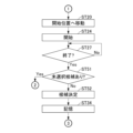
- 2 is a flowchart illustrating an example of processing according to the first embodiment by the processor in FIG. 1.
- FIG. 2 is a flowchart illustrating an example of processing performed by the processor in FIG. 1 according to the first embodiment and the second embodiment.
- the figure which shows the 1st example of the state of a tool and a spindle when a tool is made to be perpendicular
- FIG. 2 is a flowchart illustrating an example of processing performed by the processor in FIG. 1 according to the second embodiment.
- FIG. 1 is a block diagram illustrating an example of a numerical control system 1 according to a first embodiment and a main configuration of components included in the numerical control system 1.
- the numerical control system 1 includes, as an example, a numerical control device 100 and an industrial machine 200. Note that the numerical control system 1 is an example of a control system.
- the numerical control device 100 is a device that performs numerical control on an industrial machine 200 or the like.
- the numerical control device 100 also has a function (hereinafter referred to as “selection function").
- selection function a function that the "combination of angles of the rotational axes to make the tool perpendicular to the inclined surface" is hereinafter referred to as "angle combination".
- the numerical control device 100 may be a server device, a PC, a tablet terminal, a smart phone, or the like.
- the numerical control device 100 includes, for example, a processor 110, a ROM (read-only memory) 120, a RAM (random-access memory) 130, an auxiliary storage device 140, an input device 150, a display device 160, and a control interface 170.
- a bus 180 or the like connects these parts.
- the numerical control device 100 is an example of a control device. Further, when the tool is perpendicular to the inclined surface, the perpendicular is an example of a predetermined angle
- the processor 110 is a central part of a computer that performs processing such as calculations and control necessary for the operation of the numerical control device 100, and performs various calculations and processing.
- the processor 110 is, for example, a CPU (central processing unit), MPU (micro processing unit), SoC (system on a chip), DSP (digital signal processor), GPU (graphics processing unit), ASIC (application specific integrated circuit), These include a PLD (programmable logic device) or an FPGA (field-programmable gate array).
- processor 110 is a combination of more than one of these.
- the processor 110 may be a combination of these and a hardware accelerator.
- the processor 110 controls each part to realize various functions of the numerical control device 100 based on programs such as firmware, system software, application software, and NC (numerical control) program stored in the ROM 120 or the auxiliary storage device 140. Control. Furthermore, the processor 110 executes processing to be described later based on the program. Note that part or all of the program may be incorporated into the circuit of the processor 110.
- the NC program is a program for numerically controlling the industrial machine 200.
- the processor 110 functions as a program analysis section 111, a position confirmation section 112, a selection setting section 113, a candidate selection section 114, and a movement control section 115 by executing the above programs.
- the program analysis unit 111 analyzes the NC program.
- the position confirmation unit 112 selects one set from among a plurality of candidate combinations of rotation axis angles. Further, the position confirmation unit 112 causes the industrial machine 200 to perform an operation of making the tool perpendicular to the inclined surface. The position confirmation unit 112 also performs reconfirmation.
- the selection setting unit 113 determines the angle combination of the plurality of rotation axes to be used in the actual operation.
- the candidate selection unit 114 selects one set from a plurality of candidates.
- the movement control unit 115 controls the rotation axis using the angle combination determined by the selection setting unit 113.
- ROM 120 and RAM 130 are main storage devices of a computer with processor 110 at its core.
- the ROM 120 is a nonvolatile memory used exclusively for reading data.
- the ROM 120 stores, for example, firmware among the above programs.
- the ROM 120 also stores data used by the processor 110 to perform various processes.
- the RAM 130 is a memory used for reading and writing data.
- the RAM 130 is used as a work area for storing data temporarily used by the processor 110 to perform various processes.
- RAM 130 is typically volatile memory.
- the auxiliary storage device 140 is an auxiliary storage device of a computer with the processor 110 at its core.
- the auxiliary storage device 140 is, for example, an EEPROM (electric erasable programmable read-only memory), an HDD (hard disk drive), or a flash memory.
- the auxiliary storage device 140 stores, for example, system software, application software, and NC programs among the above programs. Further, the auxiliary storage device 140 stores data used by the processor 110 to perform various types of processing, data generated by processing in the processor 110, various setting values, and the like.
- the input device 150 accepts operations by the operator of the numerical control device 100.
- Input device 150 is, for example, a keyboard, keypad, touch pad, mouse, or controller.
- the input device 150 may be a device for voice input.
- the display device 160 displays a screen for notifying the operator of the numerical control device 100 of various information.
- the display device 160 is, for example, a display such as a liquid crystal display or an organic EL (electro-luminescence) display.
- a touch panel can also be used as the input device 150 and the display device 160. That is, the display panel included in the touch panel can be used as the display device 160, and the pointing device provided in the touch panel for touch input can be used as the input device 150.
- the control interface 170 is an interface for the numerical control device 100 to communicate with the industrial machine 200 and the like.
- the numerical control device 100 controls the industrial machine 200 and the like via the control interface 170 based on the NC program.
- the bus 180 includes a control bus, an address bus, a data bus, and the like, and transmits signals exchanged between each part of the numerical control device 100.
- the industrial machine 200 is a machine that operates by numerical control or the like.
- the industrial machine 200 is, for example, a machine tool, a manipulator, a robot arm, or a robot.
- Industrial machine 200 includes, as an example, an input device 210, a tool 220, and a spindle 230.
- the input device 210 accepts operations by the operator of the industrial machine 200.
- the input device 210 is, for example, an operation panel, keyboard, keypad, touch pad, touch panel, mouse, or controller.
- the input device 210 may be a device for voice input.
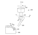
- FIG. 5 is a diagram showing a first example of the state of the tool 220 and the main shaft 230 when the tool 220 is perpendicular to the inclined surface 301 of the workpiece 300.
- the tool 220 is a tool, such as a drill, for processing the workpiece 300.
- the tool 220 can be attached to the main shaft 230.
- the main shaft 230 can rotate the tool 220 around the central axis of the tool 220, for example.
- the main shaft 230 includes a rotating shaft 231 and a rotating shaft 232.
- the rotating shaft 231 is rotatable in the B-axis direction.
- the main shaft 230 can change the direction of the tool 220 by rotating the tool 220 in the B-axis direction using the rotating shaft 231.
- the rotation shaft 232 is rotatable in the C-axis direction.
- the main shaft 230 can change the orientation of the tool 220 by rotating the tool 220 in the C-axis direction using the rotating shaft 232.
- the rotating shaft 231 and the rotating shaft 232 are typically rotatable in either positive or negative directions.
- the rotatable range of the rotating shaft 231 and the rotating shaft 232 may or may not be limited.
- the main shaft 230 may include three or more rotating shafts.
- FIGS. 2 to 4 are flowcharts showing an example of processing by the processor 110 of the numerical control device 100.
- Processor 110 executes the processes shown in FIGS. 2 to 4 based on programs stored in, for example, ROM 120 or auxiliary storage device 140.
- step ST11 of FIG. 2 the processor 110 of the numerical control device 100 determines whether or not to execute the selection function. For example, the processor 110 determines to execute the selection function when there is an operation input to the input device 150 or the input device 210 that instructs the execution of the selection function. When an operation is performed on the input device 210, the contents of the operation input are input to the numerical control device 100 via the control interface 170. Alternatively, the processor 110 determines to execute the selection function when a command or the like instructing execution of the selection function is input from an external device or the like. Additionally, processor 110 may determine to perform the selection function based on a predetermined schedule. If the processor 110 does not determine to execute the selection function, it determines No in step ST11 and repeats the process of step ST11. On the other hand, if the processor 110 determines to execute the selection function, it determines Yes in step ST11 and proceeds to step ST12.
- the processor 110 determines the target NC program to execute the selection function.
- the NC program determined here will be referred to as the "target program” hereinafter.
- the processor 110 determines a target program, for example, according to an operation input to the input device 150 or the input device 210. Alternatively, the processor 110 determines the target program based on, for example, an instruction from an external device. Alternatively, processor 110 selects an NC program that satisfies predetermined conditions as a target program.
- the predetermined condition is, for example, that the selection function has not yet been executed. Alternatively, the predetermined condition is, for example, that the setting of the angle combination in the selection function is not completed.
- step ST13 the processor 110 acquires the target program from the auxiliary storage device 140 or the like.
- the processor 110 may obtain the target program from an external storage device.
- step ST14 the processor 110 analyzes the target program.
- the processor 110 checks whether there is a vertical instruction in the target program by analysis.
- the vertical command is a command to make the tool perpendicular to the inclined surface and to set a coordinate system based on the inclined surface.
- the inclined plane is an inclined plane defined by the perpendicular command.
- the processor 110 checks the number of vertical instructions in the target program through analysis. Additionally, the processor 110 obtains other information necessary for subsequent processing through analysis.
- the program analysis unit 111 performs the process of step ST14.
- step ST15 the processor 110 determines whether or not there is an unselected vertical instruction in the target program. Selection of a vertical command is performed in step ST16. Once a vertical command is selected, it becomes selected and is no longer unselected. Note that the processor 110 determines that there is no unselected vertical instruction even when there is no vertical instruction in the target program. If the processor 110 determines that there is no unselected vertical instruction in the target program, it determines No in step ST15 and returns to step ST11. On the other hand, if the processor 110 determines that there is an unselected vertical instruction in the target program, it determines Yes in step ST15 and proceeds to step ST16.
- step ST16 if there is a selected vertical instruction (hereinafter referred to as a "selected instruction"), the processor 110 cancels the selection of the vertical instruction.
- Processor 110 selects one of the unselected vertical instructions in the target program. Note that when there are multiple unselected vertical instructions, the processor 110 selects the one to be executed first with priority.
- any two of them will be referred to as a first vertical instruction and a second vertical instruction.
- step ST17 the processor 110 determines whether or not the angle combination to be used in the actual process has been determined for the selection command. If the angle combination has been determined, the processor 110 determines Yes in step ST17 and returns to step ST15. On the other hand, if the angle combination has not been determined yet, the processor 110 makes a negative determination in step ST17 and proceeds to step ST18. Note that the determination of angle combinations will be described later.
- the processor 110 sets the combination of angles of the plurality of rotation axes to the combination selected by the selecting section. It functions as an example of a control unit that does not operate.
- step ST18 the processor 110 calculates an angle combination that makes the tool perpendicular to the inclined surface.
- the slope is a slope defined by the selection command.
- the angle combinations calculated here are candidates for angle combinations used in actual control of the industrial machine 200. If there are two rotation axes around which the tool 220 can be oriented, there are usually two sets of candidates. However, depending on the rotatable range of each rotation axis, there may be cases where there are fewer than two candidates. Further, when there are three or more rotation axes, the processor 110 may limit the combinations to be calculated to only those that satisfy a predetermined condition. Note that each combination candidate in the first vertical command is an example of the first combination. Each combination candidate in the second vertical instruction is an example of the second combination.
- FIG. 6 is a diagram showing a second example of the state of the tool 220 and the main shaft 230 when the tool 220 is perpendicular to the inclined surface 301 of the workpiece 300.
- the inclined surface 301 shown in FIGS. 5 and 6 is inclined by -30 degrees with respect to the X1 axis. Further, the inclined surface 301 is parallel to the Y1 axis.
- the X1Y1Z1 coordinate system is a coordinate system in an initial state before the tool 220 is made perpendicular to the inclined surface.
- the X2Y2Z2 coordinate system is the coordinate after the tool 220 is made perpendicular to the inclined surface 301. That is, in the X2Y2Z2 coordinate system, the inclined surface 301 is parallel to the X2Y2 plane.
- the inclined surface 301 coincides with the X2Y2 plane.
- the angle of the rotating shaft 231 is 30 degrees, and the angle of the rotating shaft 232 is 0 degrees.
- the angle of the rotation axis 231 is -30 degrees, and the angle of the rotation axis 232 is 180 degrees.
- the processor 110 calculates a plurality of angle combinations of the plurality of rotation axes that can change the direction of the tool so that the tool forms a predetermined angle with respect to the plane.
- This functions as an example of a calculation unit that performs calculations.
- step ST19 if there is an angle combination being selected (hereinafter referred to as a "selected combination"), the processor 110 cancels the selection of the angle combination.
- Processor 110 then selects one set from among the angle combinations for the selection command.
- Processor 110 automatically selects one set.
- the processor 110 randomly selects one set, for example.
- processor 110 may select one set that satisfies predetermined conditions.
- the processor 110 may select the angle combination not automatically, but based on an operation input specifying the angle combination, for example.
- the operation input is, for example, an operation input to the input device 150 of the numerical control device 100 or the input device 210 of the industrial machine 200.
- the processor 110 may select the angle combination based on an input specifying the angle combination from an external device or the like.
- the angle combination is the one calculated in step ST18.
- the processor 110 proceeds to the process in step ST20 in FIG.
- the process of step ST19 is executed by, for example, the candidate selection unit 114.
- the processor 110 functions as an example of a selection unit that selects one set from among the plurality of combinations calculated by the calculation unit.
- step ST20 of FIG. 3 the processor 110 controls the industrial machine 200 to move each part of the industrial machine 200 to the position at the time when the selection command is started (hereinafter referred to as the "start position").
- start position the position at the time when the selection command is started
- the positions of each part of the industrial machine 200 become the starting positions of the selection instruction.
- the processor 110 executes the target program up to just before the selection instruction in order to move the positions of each part of the industrial machine 200 to the starting position of the selection instruction.
- the processor 110 may move each part of the industrial machine 200 to the starting position without executing the target program.
- the processor 110 controls and operates the actual industrial machine 200 to move the position of each part of the industrial machine 200 to the starting position.
- the processor 110 may control and operate the virtual industrial machine 200 to move the position of each part of the industrial machine 200 to the starting position.
- Operating the virtual industrial machine 200 means operating the virtual industrial machine 200 in a virtual space through simulation.
- the real industrial machine 200 will be referred to as an industrial machine 200A
- the virtual industrial machine 200 will be referred to as an industrial machine 200B.
- the rotating shaft provided in the industrial machine 200A is an actual rotating shaft.
- the rotating shaft provided in the industrial machine 200B is a virtual rotating shaft.
- the processor 110 executes the target program up to just before the selection instruction, the positions of each part of the industrial machine 200 become the starting positions of the selection instruction.
- the starting position of the selection command will be explained using the following NC program "O0001" as an example.
- the N at the beginning of the NC program "O0001" and the number following the N indicate which line it is. If it is N3, it is the third line.
- the NC program "O0001" includes one vertical command.
- the first line of the NC program "O0001" is an instruction to determine the coordinate system in the initial state, that is, the X1Y1Z1 coordinate system.
- the second line of the NC program "O0001" is a command to move the tool 220 of the industrial machine 200.
- the third line of the NC program "O0001" is a command that defines the position and angle of the inclined surface 301 of the workpiece 300.
- the fourth line of the NC program "O0001" is a vertical command.
- the position after the tool 200 is moved by the command in the second line in the coordinate system determined in the first line is the start position of the vertical command in the fourth line.
- the orientation of the tool 200 at the starting position is an example of a predetermined orientation.
- the orientation of the tool 200 at the start position of the first vertical command is an example of the first predetermined orientation.
- the orientation of tool 200 at the start position of the second vertical command is an example of a second predetermined orientation.
- step ST21 the processor 110 determines whether to set at least one of the moving speed and the moving method of the industrial machine 200.
- the processor 110 sets at least one of the moving speed and the moving method when there is an operation input to the input device 150 or the input device 210 that instructs to set at least one of the moving speed and the moving method. Then it is determined.
- the processor 110 determines to set at least one of the moving speed and the moving method when a command or the like instructing to set at least one of the moving speed and the moving method is input from an external device or the like.
- the processor 110 may automatically set at least one of the movement reading rate and the movement method. In this case, the processor 110 determines to set at least one of the moving speed and the moving method only once. If the processor 110 does not determine to set at least one of the moving speed and the moving method, it determines No in step ST21 and proceeds to step ST22.
- step ST22 the processor 110 determines whether to start executing the selected instruction.
- the processor 110 determines to start executing the selected instruction when there is an operation input to the input device 150 or the input device 210 that instructs to start executing the selected instruction.
- the processor 110 determines to start executing the selected instruction when a command or the like instructing to start execution of the selected instruction is input from an external device or the like. If the processor 110 does not determine to start executing the selected instruction, it determines No in step ST22 and returns to step ST21. In this way, the processor 110 enters a standby state in which it repeats steps ST21 and ST22 until it determines to set at least one of the moving speed and the moving method of the industrial machine 200, or determines to start executing the selection command.
- processor 110 determines to set the moving speed of the industrial machine 200 while in the standby state in steps ST21 and ST22, it determines Yes in step ST21 and proceeds to step ST23.
- the processor 110 sets at least one of the moving speed and moving method of the industrial machine 200.
- the industrial machine 200 to be set is the industrial machine 200A or the industrial machine 200B.
- the processor 110 sets at least one of the moving speed and the moving method, for example, based on an operation input that instructs at least one of the moving speed and the moving method.
- the operation input is, for example, an operation input to the input device 150 of the numerical control device 100 or the input device 210 of the industrial machine 200.
- the processor 110 sets at least one of the moving speed and the moving method based on an input instructing the moving speed and/or the moving method from an external device or the like.
- the processor 110 automatically sets at least one of the moving speed and the moving method to a predetermined setting.
- the moving speed set here is preferably slower than that during normal operation. This is to prevent the tool 220 and the like from colliding with a workpiece or jig. This is also to prevent breakdowns in the event of a collision.
- Manual operation includes types such as manual handle feed, jog feed, and incremental feed.
- manual handle feed each part of the industrial machine 200 moves according to the speed of turning the handle while an operation indicating a feed instruction, such as manually turning the handle, is performed.
- jog feed each part of the industrial machine 200 moves at a set movement speed only while an operation indicating a feed instruction, such as manually pressing a switch, is on.
- incremental feed each part of the industrial machine 200 moves by a predetermined amount at a set movement speed each time an operation indicating a feed instruction, such as manually pressing a switch, is pressed once.
- a handle, a switch, and the like used for manual operation are included in the input device 210, for example.
- a handle, a switch, and the like used for manual operation may be included in the input device 150.
- step ST24 If the processor 110 determines to start executing the selection command while in the standby state in steps ST21 and ST22, it determines Yes in step ST22 and proceeds to step ST24. Further, the processor 110 may automatically start executing the selected instruction. In this case, the processor 110 skips the process of step ST22 and proceeds to step ST24.
- step ST24 the processor 110 starts executing the selected instruction to which the selected combination is applied.
- the processor 110 controls the industrial machine 200A or the industrial machine 200B to move each part so that the combination of angles of the rotation axes becomes the selected combination.
- the selection command is executed as a simulation.
- the processor 110 automatically moves each part. If the moving method is manual operation, the robot is in a standby state until an operation indicating a feed instruction is performed using a handle, a switch, or the like. Note that the execution of the selection command started in step ST24 is performed for operation confirmation. In other words, it is distinguished from the actual operation.
- step ST24 when the processor 110 executes the vertical command, it is preferable to operate the plurality of rotary axes included in the industrial machine 200 simultaneously rather than operating them one by one. This is because by operating a plurality of rotation axes simultaneously, a vertical command can be completed in a shorter time than by operating them one by one.
- the processor 110 controls the display device 160 to display the operation of the industrial machine 200B.
- the display device 160 displays the operation of the industrial machine 200B as a 2D (two-dimensional) or 3D (three-dimensional) moving image.
- the processor 110 cooperates with the display device 160 to display the operation state of the industrial machine 200B, thereby functioning as a display unit that displays the simulation results.
- the processor 110 changes the direction of the tool facing a predetermined direction and makes the tool at a predetermined angle with respect to the plane by performing the process of step ST24.
- the controller functions as an example of a control unit that controls the plurality of rotation axes so that the combination of angles of the plurality of rotation axes becomes the combination selected by the selection unit.
- the inclined surface 301 is an example of the plane.
- the inclined surface 301 in the first vertical command is an example of a first plane.
- the inclined surface 301 in the first vertical command is an example of the second plane.
- step ST25 the processor 110 determines whether to set at least one of the moving speed and the moving method of the industrial machine 200, similarly to step ST21. If the processor 110 does not determine to set at least one of the moving speed and the moving method, it determines No in step ST25 and proceeds to step ST26.
- step ST26 the processor 110 determines whether there is a sending instruction. For example, when an operation indicating a sending instruction is performed, the processor 110 determines that there is a sending instruction. Note that if the movement method of the industrial machine 200 is set to automatic operation, the processor 110 may skip the process of step ST26 and proceed to the process of step ST27. If the processor 110 determines that there is a sending instruction, the processor 110 determines No in step ST26 and proceeds to step ST27.
- step ST27 the processor 110 determines whether execution of the selected instruction has been completed. For example, the processor 110 determines that the execution of the selection command has been completed when the combination of angles of the rotation axes is a selected combination. If the processor 110 does not determine that the execution of the selection instruction has been completed, it determines No in step ST27 and returns to step ST25. In this way, the processor 110 continues in steps ST25 to ST27 until it determines to set at least one of the moving speed and the moving method of the industrial machine 200, determines that there is a feeding instruction, or determines to finish executing the selection command. It enters a standby state where the process repeats.
- processor 110 determines to set at least one of the moving speed and the moving method of the industrial machine 200 while in the standby state in steps ST25 to ST27, it determines Yes in step ST25 and proceeds to step ST28. move on.
- step ST28 the processor 110 sets at least one of the moving speed and the moving method of the industrial machine 200 in the same manner as in step ST23. After the processing in step ST28, the processor 110 returns to step ST25.
- step ST26 If the processor 110 determines that there is a sending instruction while in the standby state in steps ST25 to ST27, it determines Yes in step ST26 and proceeds to step ST29.
- step ST29 the processor 110 proceeds with the execution of the selection command according to the sending instruction.
- the industrial machine 200 moves by the amount corresponding to the feed instruction.
- the moving method of the industrial machine 200 is set to manual handle feed, the industrial machine 200 is moved at a speed corresponding to the speed at which the handle is turned. Further, the industrial machine 200 is moved only for a time corresponding to the time when the handle is turned.
- the processor 110 moves the industrial machine 200 only for a time corresponding to the length of time that the operation indicating the feed instruction continues.
- processor 110 moves industrial machine 200 by an amount corresponding to the number of times an operation indicating a feeding instruction is performed. After the processing in step ST29, the processor 110 returns to step ST25.
- the processor 110 functions as an example of a control unit by performing the processes of step ST24, step ST26, and step ST29.
- processor 110 determines that the execution of the selection command has been completed while in the standby state in steps ST25 to ST27, it determines Yes in step ST27 and proceeds to step ST30.
- step ST30 the processor 110 determines whether or not to perform reconfirmation. Reconfirmation indicates that the selection command to which the selection combination is applied is executed again. The processor 110 determines to perform the reconfirmation when there is an operation input to the input device 150 or the input device 210 that instructs the reconfirmation. Alternatively, the processor 110 determines to perform reconfirmation when a command or the like instructing reconfirmation is input from an external device or the like. If the processor 110 does not determine to perform reconfirmation, it determines No in step ST30 and proceeds to step ST31. The processing from step ST19 in FIG. 2 to step ST30 in FIG. 3 is executed, for example, by the position confirmation unit 112.
- step ST31 the processor 110 determines whether to select an angle combination. For example, processor 110 determines to select an angle combination when there is an operation input to input device 150 or input device 210 that instructs to select an angle combination. Alternatively, the processor 110 determines to select an angle combination when a command or the like instructing to select an angle combination is input from an external device or the like. If the processor 110 does not determine to select the angle combination, it determines No in step ST31 and proceeds to step ST32.
- step ST32 the processor 110 determines whether to determine the angle combination to be used in the selection command. If the processor 110 does not determine to determine the angle combination, it determines No in step ST32 and returns to step ST30. In this way, the processor 110 continues from step ST30 until it determines to reconfirm the selection command to which the selected combination is applied, or to select one of the angle combination candidates, or to determine the angle combination. A standby state is entered in which step ST32 is repeated.
- processor 110 determines to perform reconfirmation while in the standby state in steps ST30 to ST32, it determines Yes in step ST30 and returns to step ST20.
- processor 110 determines to select one of the angle combination candidates while in the standby state in steps ST30 to ST32, it determines Yes in step ST31 and returns to step ST19 in FIG. .
- step ST19 the processor 110 selects an angle combination different from the angle combination that was deselected.
- the processor 110 selects the angle combination based on an operation input specifying the angle combination, for example.
- the operation input is, for example, an operation input to the input device 150 of the numerical control device 100 or the input device 210 of the industrial machine 200.
- processor 110 selects the angle combination based on an input specifying the angle combination from an external device or the like.
- the processor 110 executes the selection command to which each candidate is applied while changing the selection of angle combinations for the selection command.
- a worker using the numerical control system 1 can visually check the operation of the industrial machine 200 when executing each selection command to which each candidate is applied, and can prevent the tool 220 from interfering with the workpiece 300 or jig. You can check to see if you have done so. Then, the operator decides which angle combination to use in the actual operation based on the confirmed results. The operator specifies to the numerical control device 200 which angle combination is to be determined by operating the input device 150 or the input device 210 or the like.
- step ST32 of FIG. 3 the processor 110 determines to determine the angle combination when, for example, there is an operation input to the input device 150 or the input device 210 specifying which angle combination to use in the selection command. do. Alternatively, the processor 110 determines to determine the angle combination when information specifying which angle combination is to be used in the selection command is input from an external device or the like. If the processor 110 determines to determine the angle combination while in the standby state in steps ST30 to ST32, it determines Yes in step ST32 and proceeds to step ST33.
- step ST33 the processor 110 determines the angle combination to be used in the selection command in the actual operation.
- Processor 110 determines the angle combination specified by the operation on input device 150, input device 210, etc. as the angle combination to be used in the selection command.
- the processor 110 determines the angle combination specified by an external device as the angle combination to be used in the selection command.
- the process of step ST33 is performed by, for example, the selection setting section 113.
- the processor 110 functions as an example of a determining unit that determines one set to be used in the actual operation from among the plurality of combinations calculated by the calculating unit by performing the process in step ST33.
- step ST34 the processor 110 stores the decision information in the auxiliary storage device 140 or the like in association with the target program and the selected instruction.
- the determination information is information indicating the angle combination determined in step ST33. After the process in step ST34, the processor 110 returns to step ST15 in FIG.
- step ST15 in FIG. 2 As described above, by repeating step ST15 in FIG. 2 to step ST34 in FIG. to be memorized.
- step ST41 of FIG. 4 the processor 110 of the numerical control device 100 acquires the NC program to be executed from the auxiliary storage device 140 or the like. Furthermore, if there is decision information associated with the NC program, the processor 110 also obtains the decision information.
- step ST42 the processor 110 starts executing the acquired NC program.
- step ST43 the processor 110 obtains the next instruction to be executed (hereinafter referred to as "next instruction"), and determines whether the obtained next instruction is a vertical instruction. If the acquired next instruction is not a vertical instruction, the processor 110 determines No in step ST43 and proceeds to step ST44.
- next instruction the next instruction to be executed
- step ST44 the processor 110 executes the next instruction obtained in step ST43.
- step ST43 determines Yes in step ST43 and proceeds to step ST45.
- step ST45 the processor 110 refers to the determination information associated with the vertical command and obtains the determined angle combination.
- the vertical command is the next command obtained last in step ST43.
- step ST46 the processor 110 executes a vertical command applying the angle combination obtained in step ST45.
- the vertical command is the next command obtained last in step ST43.
- the process of step ST46 is executed by, for example, the movement control unit 115.
- processor 110 After processing step ST44 or step ST46, processor 110 proceeds to step ST47.
- step ST47 the processor 110 determines whether to end the execution of the acquired NC program. For example, the processor 110 determines to end the execution of the NC program when there is no next instruction. If the execution of the NC program is not finished, the processor 110 makes a negative determination in step ST47 and returns to step ST43. On the other hand, if the processor 110 wants to end the execution of the NC program, it determines Yes in step ST47, ends the process of FIG. 4, and ends the execution of the NC program.
- the numerical control device 100 selects one set from among a plurality of angle combination candidates. Then, the numerical control device 100 controls and operates the industrial machine 200 by executing the vertical command to which the selected set is applied.
- the industry solution 200 also determines the angle combinations to be used in production.
- a worker or the like can check how the industrial machine 200 operates for each candidate. Therefore, a worker or the like can decide, from among the candidates, the candidate that is considered optimal as the angle combination to be used in the actual production. For example, a worker or the like can decide, from among the candidates, a candidate that does not cause interference as the angle combination to be used in the actual production. Furthermore, if there are multiple candidates that do not cause interference, the operator can, for example, determine the angle combination that takes the shortest time to complete the operation from among the candidates that do not cause interference.
- the numerical control device 100 may control the actual industrial machine 200 in the selection function. In this case, a worker or the like can see the actual product and check how the industrial machine 200 operates.
- the numerical control device 100 determines the angle combination to be used in the actual performance based on the operation input. Therefore, an operator or the like can have the numerical control device 100 use the set he/she desires in actual use.
- the numerical control device 100 may control the virtual industrial machine 200 in the selection function. That is, the numerical control device 100 of the embodiment may execute a simulation in the selection function. In this case, the numerical control device 100 of the embodiment does not need to operate the actual industrial machine 200. Therefore, the numerical control device 100 of the embodiment can execute the selection function even when the industrial machine 200 is unavailable.
- the numerical control device 100 displays simulation results. This allows workers and the like to check how the virtual industrial machine 200 operates.
- the numerical control device 100 determines the angle combination to be used in the actual production for each vertical command. Thereby, even if a plurality of vertical commands are included in the NC program, the operator can have the numerical control device 100 use the set of vertical commands that he/she desires for each vertical command.
- the numerical control device 100 skips the process for determining the combination for a vertical command for which the angle combination to be used in the actual operation has already been determined.
- the numerical control device 100 according to the embodiment can prevent an operator or the like from unnecessaryly checking the operation again for a vertical command for which the angle combination to be used in the actual operation has already been determined.
- the numerical control device 100 automatically determines the angle combination to be used in the selection command.
- the configuration of the numerical control system 1 of the second embodiment is the same as that of the first embodiment.
- FIGS. 2, 4, 7, etc. are flowcharts showing an example of processing by the processor 110 of the numerical control device 100.
- the processor 110 executes the processes shown in FIGS. 2, 4, and 7 based on programs stored in, for example, the ROM 120 or the auxiliary storage device 140.
- the processor 110 executes the processes in FIGS. 2 and 4 similarly to the first embodiment. In the second embodiment, the processor 110 executes the process shown in FIG. 7 instead of FIG. 3.
- the processor 110 controls the industrial machine 200B to move each part of the industrial machine 200B to the starting position in step ST20 of FIG.
- the processor 110 proceeds to step ST24 after processing in step ST20.
- the processor 110 controls the industrial machine 200B in step ST24. That is, in the second embodiment, execution of a selection instruction to which a selection combination is applied is limited to simulation. Furthermore, in the second embodiment, the method of moving the industrial machine 200B is automatic operation. Further, in the second embodiment, it is preferable that the processor 110 performs the simulation at a speed that corresponds to the processing speed of the processor 110 without considering the setting of the moving speed. Therefore, the processor 110 does not need to set the moving speed.
- the processor 110 proceeds to step ST27 after processing in step ST24.
- step ST27 if the processor 110 determines No in step ST27, the process returns to step ST27. If the processor 110 determines Yes in step ST27, it proceeds to step ST51.
- step ST51 the processor 110 determines whether there is any unselected angle combination.
- the angle combination is calculated in step ST18 in FIG. 2. Selection of angle combinations is performed in step ST19. Once an angle combination has been selected, it becomes selected and is no longer unselected. If there is an unselected angle combination, the processor 110 determines Yes in step ST51 of FIG. 3 and returns to step ST19 of FIG. 2.
- the processor 110 selects from unselected angle combinations in step ST19.
- step ST51 determines No in step ST51 and proceeds to step ST52.
- the processor 110 repeats step ST19, step ST20, step ST24, step ST27, and step ST51 in FIGS. 2 and 7 to execute the selection command applying each of the angle combinations calculated in step ST18. .
- step ST52 of FIG. 7 the processor 110 selects the optimal angle combination from among the plurality of angle combinations and determines it as the angle combination to be used in the actual performance.
- the optimal one is, for example, one that takes the shortest time to complete the movable property among those that do not cause interference. Note that interference occurs, for example, between the tool 220 or the like and the workpiece 300 or the jig.
- the processor 110 proceeds to step ST34.
- the processor 110 functions as an example of a determining unit by performing the process of step ST52.
- the decision information in step ST34 of the second embodiment is information indicating the angle combination determined in step ST52.
- the numerical control device 100 automatically selects angle combinations. Further, the numerical control device 100 of the embodiment automatically determines the angle combination to be used in the actual performance. Thereby, the numerical control device 100 of the embodiment can reduce the labor of the operator and the like.
- the numerical control device 100 makes the tool 220 perpendicular to the inclined surface 301.
- the numerical control device 100 may use other angles instead of vertical.
- the other angle is an example of a predetermined angle.
- the numerical control device 100 does not need to have the function of controlling the industrial machine 200A. In this case, the numerical control device 100 does not execute the process shown in FIG. 4.
- the processor 110 may implement part or all of the processing implemented by the program in the above embodiments using a circuit hardware configuration.
- a program that implements the processing of the embodiment is transferred, for example, while being stored in a non-temporary recording medium within the device.
- the device may be transferred without the program stored therein.
- the program may be separately transferred and written into the device. Transfer of the program at this time can be realized, for example, by recording it on a removable, non-temporary storage medium, or by downloading it via a network such as the Internet or a LAN (local area network).
Landscapes
- Engineering & Computer Science (AREA)
- Human Computer Interaction (AREA)
- Manufacturing & Machinery (AREA)
- Physics & Mathematics (AREA)
- General Physics & Mathematics (AREA)
- Automation & Control Theory (AREA)
- Mechanical Engineering (AREA)
- Numerical Control (AREA)
Abstract
Description
〔第1実施形態〕
図1は、第1実施形態に係る数値制御システム1及び数値制御システム1に含まれる構成要素の要部構成の一例を示すブロック図である。数値制御システム1は、一例として、数値制御装置100及び産業機械200を含む。なお、数値制御システム1は、制御システムの一例である。
なお、数値制御装置100は、制御装置の一例である。また、傾斜面に対して工具を垂直にする場合の当該垂直は、所定の角度の一例である。
ROM120は、専らデータの読み出しに用いられる不揮発性メモリである。ROM120は、上記のプログラムのうち、例えばファームウェアなどを記憶する。また、ROM120は、プロセッサー110が各種の処理を行う上で使用するデータなども記憶する。
RAM130は、データの読み書きに用いられるメモリである。RAM130は、プロセッサー110が各種の処理を行う上で一時的に使用するデータを記憶するワークエリアなどとして利用される。RAM130は、典型的には揮発性メモリである。
図5は、ワーク300の傾斜面301に対して工具220が垂直になるようにした場合の工具220及び主軸230の状態の第1の例を示す図である。
図2のステップST11において数値制御装置100のプロセッサー110は、選択機能を実行するか否かを判定する。プロセッサー110は、例えば、入力デバイス150又は入力デバイス210などに対して選択機能の実行を指示する操作入力があった場合に、選択機能を実行すると判定する。入力デバイス210に対して操作が行われた場合、操作入力の内容は、制御インターフェース170を介して数値制御装置100に入力する。あるいは、プロセッサー110は、外部の装置などから、選択機能の実行を指示するコマンドなどの入力があった場合に、選択機能を実行すると判定する。また、プロセッサー110は、予め定められたスケジュールに基づき選択機能を実行すると判定しても良い。プロセッサー110は、選択機能を実行すると判定しないならば、ステップST11においてNoと判定してステップST11の処理を繰り返す。対して、プロセッサー110は、選択機能を実行すると判定するならば、ステップST11においてYesと判定してステップST12へと進む。
また、プロセッサー110は、解析により、対象プログラム中の垂直命令の数を調べる。また、プロセッサー110は、解析により、以降の処理で必要なその他の情報を得る。
例えば、プログラム解析部111がステップST14の処理を行う。
なお、第1の垂直命令における各組み合わせの候補は、第1の組み合わせの一例である。第2の垂直命令における各組み合わせの候補は、第2の組み合わせの一例である。
図6は、ワーク300の傾斜面301に対して工具220が垂直になるようにした場合の工具220及び主軸230の状態の第2の例を示す図である。
ステップST19の処理は、例えば、候補選択部114が実行する。
産業機械200Aが備える回転軸は、実物の回転軸である。産業機械200Bが備える回転軸は、仮想の回転軸である。
選択命令の開始位置について、以下のNCプログラム「O0001」を例に説明する。
N1 G54
N2 G90 G00 X200.0 Y200.0 Z300.0 B0 C90.0
N3 G68.2 P1 X50.0 Y0 Z100.0 I0 J30.0 K0
N4 G53.1
N5 G43 H1 X0 Y0 Z0
なお、開始位置における工具200の向きは、所定の向きの一例である。なお、第1の垂直命令の開始位置における工具200の向きは、第1の所定の向きの一例である。第2の垂直命令の開始位置における工具200の向きは、第2の所定の向きの一例である。
プロセッサー110は、ステップST29の処理の後、ステップST25へと戻る。
図2のステップST19~図3のステップST30の処理は、例えば位置確認部112が実行する。
プロセッサー110は、ステップST30~ステップST32の待受状態にあるときに角度組み合わせを決定すると判定するならば、ステップST32においてYesと判定してステップST33へと進む。
ステップST33の処理は、例えば、選択設定部113が行う。
ステップST46の処理は、例えば、移動制御部115が実行する。
ステップST47においてプロセッサー110は、取得したNCプログラムの実行を終了するか否かを判定する。プロセッサー110は、例えば、次命令が無い場合にNCプログラムの実行を終了すると判定する。プロセッサー110は、NCプログラムの実行を終了しないならば、ステップST47においてNoと判定してステップST43へと戻る。対して、プロセッサー110は、NCプログラムの実行を終了するならば、ステップST47においてYesと判定して図4の処理を終了し、NCプログラムの実行を終了する。
第2実施形態では、選択命令において使用する角度組み合わせを数値制御装置100が自動で決定する。
第2実施形態の数値制御システム1の構成は、第1実施形態と同様である。
上記の実施形態では、数値制御装置100は、工具220を傾斜面301に対して垂直にする。しかしながら、数値制御装置100は、垂直に代えて他の角度を用いても良い。当該他の角度は、所定の角度の一例である。
100 数値制御装置
110 プロセッサー
111 プログラム解析部
112 位置確認部
113 選択設定部
114 候補選択部
115 移動制御部
120 ROM
130 RAM
140 補助記憶装置
150,210 入力デバイス
160 表示デバイス
170 制御インターフェース
180 バス
200 産業機械
220 工具
230 主軸
231,232 回転軸
Claims (11)
- 工具の向きを変えることが可能な複数の回転軸の、前記工具が平面に対して所定の角度となるような角度の組み合わせを複数算出する算出部と、
前記算出部によって算出された複数の前記組み合わせの中から1組を選択する選択部と、
所定の向きを向いた前記工具の向きを変えて前記工具が前記平面に対して所定の角度となるようにするために、前記複数の回転軸を制御して、前記複数の回転軸の角度の組み合わせを前記選択部によって選択された前記組み合わせになるように動作させる制御部と、
前記算出部によって算出された複数の前記組み合わせの中から、本番の動作で使用する1組を決定する決定部と、を備える制御装置。 - 前記回転軸は、実物の回転軸である、請求項1に記載の制御装置。
- 前記決定部は、操作入力に基づいて1組を決定する、請求項1に記載の制御装置。
- 前記回転軸は、仮想の回転軸であり、
前記回転軸の動作は、前記制御部によるシミュレーションである、請求項1に記載の制御装置。 - 前記シミュレーションの結果を表示する表示部をさらに備える、請求項4に記載の制御装置。
- 前記選択部は、前記算出部によって算出された複数の前記組み合わせの中から1組を選択することを、前記算出部によって算出された複数の前記組み合わせそれぞれについて実行し、
前記制御部は、前記複数の回転軸を制御して、前記複数の回転軸の角度の組み合わせを前記選択部によって選択された前記組み合わせになるように動作させることを、前記選択部によって選択される複数の前記組み合わせそれぞれについて実行し、
前記決定部は、干渉を起こさない前記1組を決定する、請求項4に記載の制御装置。 - 前記制御部は、前記複数の回転軸を同時に動作させる、請求項1に記載の制御装置。
- 前記算出部は、前記工具が第1の平面に対して前記所定の角度となるような角度の第1の組み合わせを複数と、前記工具が第2の平面に対して前記所定の角度となるような角度の第2の組み合わせを複数算出し、
前記制御部は、第1の所定の向きを向いた前記工具の向きを変えて前記工具が前記第1の平面に対して前記所定の角度となるようにするために、前記複数の回転軸を制御して、前記複数の回転軸の角度の組み合わせを前記算出部によって算出された前記第1の組み合わせになるように動作させることを、前記算出部によって算出された複数の前記第1の組み合わせそれぞれについて実行し、第2の所定の向きを向いた前記工具の向きを変えて前記工具が前記第2の平面に対して前記所定の角度となるようにするために、前記複数の回転軸を制御して、前記複数の回転軸の角度の組み合わせを前記算出部によって算出された前記第2の組み合わせになるように動作させることを、前記算出部によって算出された複数の前記第2の組み合わせそれぞれについて実行し、
前記決定部は、前記算出部によって算出された複数の前記第1の組み合わせの中から、本番の動作で使用する1組を決定し、前記算出部によって算出された複数の前記第2の組み合わせの中から、本番の動作で使用する1組を決定する、請求項1に記載の制御装置。 - 前記制御部は、前記決定部によって1組の前記組み合わせが決定済みである場合、前記複数の回転軸の角度の組み合わせを前記選択部によって選択された前記組み合わせになるように動作させることを行わない、請求項1に記載の制御装置。
- 制御装置と、工具の向きを変えることが可能な複数の回転軸を含む産業機械とを含み、
前記制御装置は、
前記複数の回転軸の、前記工具が平面に対して所定の角度となるような角度の組み合わせを複数算出する算出部と、
前記算出部によって算出された複数の前記組み合わせの中から1組を選択する選択部と、
所定の向きを向いた前記工具の向きを変えて前記工具が前記平面に対して所定の角度となるようにするために、前記複数の回転軸を制御して、前記複数の回転軸の角度の組み合わせを前記選択部によって選択された前記組み合わせになるように動作させる制御部と、
前記算出部によって算出された複数の前記組み合わせの中から、本番の動作で使用する1組を決定する決定部と、を備える制御システム。
システム - 制御装置が備えるプロセッサーを、
工具の向きを変えることが可能な複数の回転軸の、前記工具が平面に対して所定の角度となるような角度の組み合わせを複数算出する算出部と、
前記算出部によって算出された複数の前記組み合わせの中から1組を選択する選択部と、
所定の向きを向いた前記工具の向きを変えて前記工具が前記平面に対して所定の角度となるようにするために、前記複数の回転軸を制御して、前記複数の回転軸の角度の組み合わせを前記選択部によって選択された前記組み合わせになるように動作させる制御部と、
前記算出部によって算出された複数の前記組み合わせの中から、本番の動作で使用する1組を決定する決定部と、して機能させるプログラム。
Priority Applications (5)
| Application Number | Priority Date | Filing Date | Title |
|---|---|---|---|
| JP2024538591A JPWO2024029007A1 (ja) | 2022-08-03 | 2022-08-03 | |
| US18/875,362 US20250383647A1 (en) | 2022-08-03 | 2022-08-03 | Control device, control system, and program |
| DE112022007185.0T DE112022007185T5 (de) | 2022-08-03 | 2022-08-03 | Steuergerät, Steuersystem und Programm |
| CN202280098153.7A CN119585683A (zh) | 2022-08-03 | 2022-08-03 | 控制装置、控制系统以及程序 |
| PCT/JP2022/029815 WO2024029007A1 (ja) | 2022-08-03 | 2022-08-03 | 制御装置、制御システム及びプログラム |
Applications Claiming Priority (1)
| Application Number | Priority Date | Filing Date | Title |
|---|---|---|---|
| PCT/JP2022/029815 WO2024029007A1 (ja) | 2022-08-03 | 2022-08-03 | 制御装置、制御システム及びプログラム |
Publications (1)
| Publication Number | Publication Date |
|---|---|
| WO2024029007A1 true WO2024029007A1 (ja) | 2024-02-08 |
Family
ID=89848693
Family Applications (1)
| Application Number | Title | Priority Date | Filing Date |
|---|---|---|---|
| PCT/JP2022/029815 Ceased WO2024029007A1 (ja) | 2022-08-03 | 2022-08-03 | 制御装置、制御システム及びプログラム |
Country Status (5)
| Country | Link |
|---|---|
| US (1) | US20250383647A1 (ja) |
| JP (1) | JPWO2024029007A1 (ja) |
| CN (1) | CN119585683A (ja) |
| DE (1) | DE112022007185T5 (ja) |
| WO (1) | WO2024029007A1 (ja) |
Citations (1)
| Publication number | Priority date | Publication date | Assignee | Title |
|---|---|---|---|---|
| JP2019204354A (ja) * | 2018-05-24 | 2019-11-28 | ファナック株式会社 | 数値制御装置 |
-
2022
- 2022-08-03 US US18/875,362 patent/US20250383647A1/en active Pending
- 2022-08-03 CN CN202280098153.7A patent/CN119585683A/zh active Pending
- 2022-08-03 WO PCT/JP2022/029815 patent/WO2024029007A1/ja not_active Ceased
- 2022-08-03 DE DE112022007185.0T patent/DE112022007185T5/de active Pending
- 2022-08-03 JP JP2024538591A patent/JPWO2024029007A1/ja active Pending
Patent Citations (1)
| Publication number | Priority date | Publication date | Assignee | Title |
|---|---|---|---|---|
| JP2019204354A (ja) * | 2018-05-24 | 2019-11-28 | ファナック株式会社 | 数値制御装置 |
Also Published As
| Publication number | Publication date |
|---|---|
| US20250383647A1 (en) | 2025-12-18 |
| CN119585683A (zh) | 2025-03-07 |
| DE112022007185T5 (de) | 2025-04-30 |
| JPWO2024029007A1 (ja) | 2024-02-08 |
Similar Documents
| Publication | Publication Date | Title |
|---|---|---|
| JP6012712B2 (ja) | 工具経路生成方法、工具経路生成装置および工具経路生成プログラム | |
| JP5414948B1 (ja) | 数値制御装置 | |
| JP6320668B1 (ja) | 数値制御装置および数値制御方法 | |
| JP7348013B2 (ja) | シミュレーション装置 | |
| JP5957070B2 (ja) | ワーク加工面表示方法、ワーク加工面表示装置、工具経路生成装置およびワーク加工面表示プログラム | |
| JP2002172543A (ja) | 加工装置の制御パラメータ設定装置及び制御パラメータ設定方法 | |
| JP2019188558A (ja) | 工具選定装置及び機械学習装置 | |
| JP2009301232A (ja) | 座標変換工具位相制御用数値制御装置 | |
| JP4505295B2 (ja) | Nc加工シミュレーション方法及びnc加工シミュレーション装置 | |
| KR100314748B1 (ko) | 실시간 3차원 그래픽 표시기능을 갖는 수치제어시스템 및 방법 | |
| WO2022034848A1 (ja) | 数値制御システム及びロボット制御方法 | |
| JP2005288563A (ja) | 加工プログラム作成方法、及び加工プログラム作成装置 | |
| WO2024029007A1 (ja) | 制御装置、制御システム及びプログラム | |
| JP5272447B2 (ja) | 数値制御機械の動作シミュレータ | |
| JP4549051B2 (ja) | 工作機械の軸制御装置、工作機械の軸制御プログラム | |
| JP2011014029A (ja) | 工作機械の衝突防止方法 | |
| JP7157281B1 (ja) | ロボット制御装置、数値制御システム及び数値制御方法 | |
| JP4867876B2 (ja) | 数値制御装置、数値制御プログラム及び数値制御プログラムを記憶した記憶媒体 | |
| JP7842229B2 (ja) | 処理装置、プログラム及び処理方法 | |
| Al’Hapis et al. | A framework for a feature based machining using macro | |
| JP7414849B2 (ja) | 移動経路描画装置 | |
| JP7440614B2 (ja) | プログラム解析装置及び制御システム | |
| JP4036151B2 (ja) | 数値制御装置及び数値制御方法 | |
| García et al. | Computer Numerical Control (CNC) | |
| KR101522430B1 (ko) | 실시간 시뮬레이터를 이용한 파트 프로그램의 그래픽 설명 정보 제공 장치 및 방법 |
Legal Events
| Date | Code | Title | Description |
|---|---|---|---|
| 121 | Ep: the epo has been informed by wipo that ep was designated in this application |
Ref document number: 22953996 Country of ref document: EP Kind code of ref document: A1 |
|
| WWE | Wipo information: entry into national phase |
Ref document number: 2024538591 Country of ref document: JP |
|
| WWE | Wipo information: entry into national phase |
Ref document number: 18875362 Country of ref document: US |
|
| WWE | Wipo information: entry into national phase |
Ref document number: 112022007185 Country of ref document: DE |
|
| WWE | Wipo information: entry into national phase |
Ref document number: 202280098153.7 Country of ref document: CN |
|
| WWP | Wipo information: published in national office |
Ref document number: 202280098153.7 Country of ref document: CN |
|
| WWP | Wipo information: published in national office |
Ref document number: 112022007185 Country of ref document: DE |
|
| 122 | Ep: pct application non-entry in european phase |
Ref document number: 22953996 Country of ref document: EP Kind code of ref document: A1 |
|
| WWP | Wipo information: published in national office |
Ref document number: 18875362 Country of ref document: US |