WO2024028948A1 - 電気車駆動システム - Google Patents
電気車駆動システム Download PDFInfo
- Publication number
- WO2024028948A1 WO2024028948A1 PCT/JP2022/029508 JP2022029508W WO2024028948A1 WO 2024028948 A1 WO2024028948 A1 WO 2024028948A1 JP 2022029508 W JP2022029508 W JP 2022029508W WO 2024028948 A1 WO2024028948 A1 WO 2024028948A1
- Authority
- WO
- WIPO (PCT)
- Prior art keywords
- electric vehicle
- control devices
- control device
- drive system
- cooler
- Prior art date
- Legal status (The legal status is an assumption and is not a legal conclusion. Google has not performed a legal analysis and makes no representation as to the accuracy of the status listed.)
- Ceased
Links
Images


Classifications
-
- B—PERFORMING OPERATIONS; TRANSPORTING
- B60—VEHICLES IN GENERAL
- B60L—PROPULSION OF ELECTRICALLY-PROPELLED VEHICLES; SUPPLYING ELECTRIC POWER FOR AUXILIARY EQUIPMENT OF ELECTRICALLY-PROPELLED VEHICLES; ELECTRODYNAMIC BRAKE SYSTEMS FOR VEHICLES IN GENERAL; MAGNETIC SUSPENSION OR LEVITATION FOR VEHICLES; MONITORING OPERATING VARIABLES OF ELECTRICALLY-PROPELLED VEHICLES; ELECTRIC SAFETY DEVICES FOR ELECTRICALLY-PROPELLED VEHICLES
- B60L3/00—Electric devices on electrically-propelled vehicles for safety purposes; Monitoring operating variables, e.g. speed, deceleration or energy consumption
- B60L3/0023—Detecting, eliminating, remedying or compensating for drive train abnormalities, e.g. failures within the drive train
- B60L3/003—Detecting, eliminating, remedying or compensating for drive train abnormalities, e.g. failures within the drive train relating to inverters
-
- B—PERFORMING OPERATIONS; TRANSPORTING
- B60—VEHICLES IN GENERAL
- B60L—PROPULSION OF ELECTRICALLY-PROPELLED VEHICLES; SUPPLYING ELECTRIC POWER FOR AUXILIARY EQUIPMENT OF ELECTRICALLY-PROPELLED VEHICLES; ELECTRODYNAMIC BRAKE SYSTEMS FOR VEHICLES IN GENERAL; MAGNETIC SUSPENSION OR LEVITATION FOR VEHICLES; MONITORING OPERATING VARIABLES OF ELECTRICALLY-PROPELLED VEHICLES; ELECTRIC SAFETY DEVICES FOR ELECTRICALLY-PROPELLED VEHICLES
- B60L15/00—Methods, circuits, or devices for controlling the traction-motor speed of electrically-propelled vehicles
- B60L15/007—Physical arrangements or structures of drive train converters specially adapted for the propulsion motors of electric vehicles
-
- B—PERFORMING OPERATIONS; TRANSPORTING
- B60—VEHICLES IN GENERAL
- B60L—PROPULSION OF ELECTRICALLY-PROPELLED VEHICLES; SUPPLYING ELECTRIC POWER FOR AUXILIARY EQUIPMENT OF ELECTRICALLY-PROPELLED VEHICLES; ELECTRODYNAMIC BRAKE SYSTEMS FOR VEHICLES IN GENERAL; MAGNETIC SUSPENSION OR LEVITATION FOR VEHICLES; MONITORING OPERATING VARIABLES OF ELECTRICALLY-PROPELLED VEHICLES; ELECTRIC SAFETY DEVICES FOR ELECTRICALLY-PROPELLED VEHICLES
- B60L15/00—Methods, circuits, or devices for controlling the traction-motor speed of electrically-propelled vehicles
- B60L15/32—Control or regulation of multiple-unit electrically-propelled vehicles
-
- B—PERFORMING OPERATIONS; TRANSPORTING
- B60—VEHICLES IN GENERAL
- B60L—PROPULSION OF ELECTRICALLY-PROPELLED VEHICLES; SUPPLYING ELECTRIC POWER FOR AUXILIARY EQUIPMENT OF ELECTRICALLY-PROPELLED VEHICLES; ELECTRODYNAMIC BRAKE SYSTEMS FOR VEHICLES IN GENERAL; MAGNETIC SUSPENSION OR LEVITATION FOR VEHICLES; MONITORING OPERATING VARIABLES OF ELECTRICALLY-PROPELLED VEHICLES; ELECTRIC SAFETY DEVICES FOR ELECTRICALLY-PROPELLED VEHICLES
- B60L9/00—Electric propulsion with power supply external to the vehicle
- B60L9/16—Electric propulsion with power supply external to the vehicle using AC induction motors
- B60L9/18—Electric propulsion with power supply external to the vehicle using AC induction motors fed from DC supply lines
- B60L9/22—Electric propulsion with power supply external to the vehicle using AC induction motors fed from DC supply lines polyphase motors
-
- B—PERFORMING OPERATIONS; TRANSPORTING
- B60—VEHICLES IN GENERAL
- B60L—PROPULSION OF ELECTRICALLY-PROPELLED VEHICLES; SUPPLYING ELECTRIC POWER FOR AUXILIARY EQUIPMENT OF ELECTRICALLY-PROPELLED VEHICLES; ELECTRODYNAMIC BRAKE SYSTEMS FOR VEHICLES IN GENERAL; MAGNETIC SUSPENSION OR LEVITATION FOR VEHICLES; MONITORING OPERATING VARIABLES OF ELECTRICALLY-PROPELLED VEHICLES; ELECTRIC SAFETY DEVICES FOR ELECTRICALLY-PROPELLED VEHICLES
- B60L2200/00—Type of vehicles
- B60L2200/26—Rail vehicles
-
- B—PERFORMING OPERATIONS; TRANSPORTING
- B60—VEHICLES IN GENERAL
- B60L—PROPULSION OF ELECTRICALLY-PROPELLED VEHICLES; SUPPLYING ELECTRIC POWER FOR AUXILIARY EQUIPMENT OF ELECTRICALLY-PROPELLED VEHICLES; ELECTRODYNAMIC BRAKE SYSTEMS FOR VEHICLES IN GENERAL; MAGNETIC SUSPENSION OR LEVITATION FOR VEHICLES; MONITORING OPERATING VARIABLES OF ELECTRICALLY-PROPELLED VEHICLES; ELECTRIC SAFETY DEVICES FOR ELECTRICALLY-PROPELLED VEHICLES
- B60L2210/00—Converter types
- B60L2210/40—DC to AC converters
- B60L2210/44—Current source inverters
-
- B—PERFORMING OPERATIONS; TRANSPORTING
- B60—VEHICLES IN GENERAL
- B60L—PROPULSION OF ELECTRICALLY-PROPELLED VEHICLES; SUPPLYING ELECTRIC POWER FOR AUXILIARY EQUIPMENT OF ELECTRICALLY-PROPELLED VEHICLES; ELECTRODYNAMIC BRAKE SYSTEMS FOR VEHICLES IN GENERAL; MAGNETIC SUSPENSION OR LEVITATION FOR VEHICLES; MONITORING OPERATING VARIABLES OF ELECTRICALLY-PROPELLED VEHICLES; ELECTRIC SAFETY DEVICES FOR ELECTRICALLY-PROPELLED VEHICLES
- B60L2240/00—Control parameters of input or output; Target parameters
- B60L2240/10—Vehicle control parameters
- B60L2240/36—Temperature of vehicle components or parts
-
- B—PERFORMING OPERATIONS; TRANSPORTING
- B60—VEHICLES IN GENERAL
- B60L—PROPULSION OF ELECTRICALLY-PROPELLED VEHICLES; SUPPLYING ELECTRIC POWER FOR AUXILIARY EQUIPMENT OF ELECTRICALLY-PROPELLED VEHICLES; ELECTRODYNAMIC BRAKE SYSTEMS FOR VEHICLES IN GENERAL; MAGNETIC SUSPENSION OR LEVITATION FOR VEHICLES; MONITORING OPERATING VARIABLES OF ELECTRICALLY-PROPELLED VEHICLES; ELECTRIC SAFETY DEVICES FOR ELECTRICALLY-PROPELLED VEHICLES
- B60L2240/00—Control parameters of input or output; Target parameters
- B60L2240/40—Drive Train control parameters
- B60L2240/52—Drive Train control parameters related to converters
- B60L2240/525—Temperature of converter or components thereof
-
- Y—GENERAL TAGGING OF NEW TECHNOLOGICAL DEVELOPMENTS; GENERAL TAGGING OF CROSS-SECTIONAL TECHNOLOGIES SPANNING OVER SEVERAL SECTIONS OF THE IPC; TECHNICAL SUBJECTS COVERED BY FORMER USPC CROSS-REFERENCE ART COLLECTIONS [XRACs] AND DIGESTS
- Y02—TECHNOLOGIES OR APPLICATIONS FOR MITIGATION OR ADAPTATION AGAINST CLIMATE CHANGE
- Y02T—CLIMATE CHANGE MITIGATION TECHNOLOGIES RELATED TO TRANSPORTATION
- Y02T10/00—Road transport of goods or passengers
- Y02T10/60—Other road transportation technologies with climate change mitigation effect
- Y02T10/72—Electric energy management in electromobility
Definitions
- the present disclosure relates to an electric vehicle drive system that includes a plurality of electric vehicle control devices that control electric motors that drive electric vehicles.
- An electric vehicle control device (hereinafter abbreviated as "control device” as appropriate) operates by receiving power from overhead wires, so it is often mounted on the roof or under the floor of an electric vehicle.
- the control device has an inverter in which a semiconductor element is incorporated.
- the inverter is electrically connected to the electric motor for driving.
- DC power is supplied to the inverter.
- the DC power is converted into desired AC power by switching the semiconductor elements of the inverter, and is supplied to the motor.
- the electric motor is driven by the converted AC power.
- the semiconductor elements of the inverter perform a switching operation, they generate heat. For this reason, a cooler is attached to the casing that houses the inverter.
- Patent Document 1 describes a running wind cooling type cooler that cools an inverter by using running wind when an electric car is running, and describes a cooling system in which two coolers are arranged close to each other in series along the traveling direction of an electric car.
- a configuration is disclosed in which the device is arranged as follows.
- Patent Document 1 it is difficult to efficiently cool multiple inverters. For example, if the area of the cooler is divided into windward and leeward areas with respect to the traveling wind, the inverter cooled by the cooler located on the windward side is easily cooled because the traveling wind is efficiently taken in. On the other hand, for an inverter that is cooled by a cooler located on the leeward side, the two coolers are close together, making it difficult for the running wind to be taken into the cooler on the leeward side, and the inverter is also cooled by a cooler located on the windward side. Due to the heat generated by the inverter, the temperature of the running air tends to rise, making cooling conditions stricter.
- Patent Document 1 a structure is adopted in which a wind guide is provided for guiding the traveling wind to the cooler on the leeward side. In any case, with the conventional method, the problem arises that the control device becomes larger and the manufacturing cost of the control device increases.
- control device when the control device is mounted under the floor of an electric vehicle, the space under the floor is limited, so there may not be enough space to mount the control device casing. In such a case, it is necessary to reduce the size of the component parts and downsize the casing by, for example, changing the specifications of the control device. Note that reviewing the specifications may have the disadvantage that the functions or performance of the electric vehicle may be lower than originally.
- the present disclosure has been made in view of the above, and an object of the present disclosure is to obtain an electric vehicle drive system in which a control device can be flexibly arranged in a limited space of an electric vehicle so as to enable efficient cooling. With the goal.
- an electric vehicle drive system includes a control system that controls at least one of four electric motors that drive four axles of two bogies of an electric vehicle. Equipped with multiple devices.
- Each of the control devices includes an inverter that supplies power to at least one electric motor, and a control section that controls the inverter.
- the inverter is housed in a housing together with a control unit, and each of the housings houses at least one control device.
- Each of the casings is equipped with a cooler that cools the inverter using the wind generated by the running of the electric vehicle.
- the plurality of control devices are arranged in a distributed manner near a first trolley located at the front in the direction of travel of the electric vehicle and near a second trolley located at the rear in the direction of travel of the electric vehicle.
- control device can be flexibly arranged in the limited space of the electric vehicle so as to enable efficient cooling.
- a diagram showing a configuration example of an electric vehicle drive system according to Embodiment 1 Diagram showing a conventional installation example shown as a comparative example A first diagram for explaining a first installation example of the electric vehicle drive system according to the first embodiment A second diagram for explaining the first installation example of the electric vehicle drive system according to the first embodiment A diagram for explaining a second installation example of the electric vehicle drive system according to Embodiment 1 A diagram for explaining a third installation example of the electric vehicle drive system according to Embodiment 1 A diagram for explaining a fourth mounting example of the electric vehicle drive system according to Embodiment 1 Diagram showing the results of the first verification test to explain the influence of obstacles on the air flow to the cooler Diagram showing the results of the second verification test to explain the influence of obstacles on the air flow to the cooler A diagram for explaining an example of mounting an electric vehicle drive system according to Embodiment 2
- connection includes both cases where components are directly connected to each other and cases where components are indirectly connected to each other via other components.
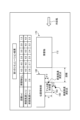
- FIG. 1 is a diagram showing a configuration example of an electric vehicle drive system according to the first embodiment.
- FIG. 1 shows an example of the configuration for one electric car.
- the electric vehicle drive system 200 includes four control devices 100 to 103 that receive DC power from the overhead wire 1 via the current collector 2. There is a substation (not shown) at the end of the overhead wire 1, and the overhead wire 1 is positioned as an external power source when viewed from the control devices 100 to 103.
- the overhead wire voltage which is the voltage of the overhead wire 1 applied to the current collector 2, and each conversion capacity of the control devices 100 to 103 differ depending on the drive method of the electric vehicle drive system.
- the range of the overhead wire voltage is approximately 600 to 3000 [V]. Further, the range of conversion capacity is from several tens to several hundreds [kVA].
- the electric motors 80 to 83 for driving the electric vehicle are connected to each of the control devices 100 to 103, respectively.
- DC power supplied from the overhead wire 1 and the current collector 2 is supplied to the control devices 100 to 103 via the switch 10, the reactor 11, and the electric wire 20.
- Each positive side terminal P of the control devices 100 to 103 is connected to the reactor 11.
- each negative side terminal N of the control devices 100 to 103 is connected to the rail 4 via the wheel 3.
- the DC current caused by the DC power supplied from the overhead wire 1 flows through the switch 10, the reactor 11, the electric wire 20, the control devices 100 to 103, the electric motors 80 to 83, the wheels 3 and the rails 4, and returns to the substation.
- the reactor 11, the electric wire 20, and the control devices 100 to 103 are the constituent elements of the electric vehicle drive system 200.
- the electric wire 20 includes a conductor such as copper or aluminum.
- An example of a conductor is a bus bar.
- FIG. 1 shows an overhead wire as the overhead wire 1 and a pantograph-shaped current collector as the current collector 2, the present invention is not limited to these.
- the overhead wire 1 may be a third rail used in a subway or the like, and accordingly, the current collector 2 may be a current collector for the third rail.
- FIG. 1 shows a case where the overhead wire 1 is a DC overhead wire, the overhead wire 1 may be an AC overhead wire.
- a transformer is provided between the current collector 2 and the switch 10 or between the switch 10 and the reactor 11 to step down the AC voltage received.
- a converter that converts the AC voltage output from the transformer into DC voltage is provided downstream of the transformer.
- the control device 100 includes a capacitor 50 that holds DC voltage, a discharge circuit 52 that discharges the voltage of the capacitor 50, and an inverter 60.
- the capacitor 50 and the discharge circuit 52 are connected between the positive terminal P and the negative terminal N inside the control device 100. Thereby, the capacitor 50 and the discharge circuit 52 are connected in parallel to both ends of the inverter 60 on the input side of the inverter 60.
- the capacitor 50 is connected to the reactor 11 and forms an LC filter circuit together with the reactor 11.
- This LC filter circuit suppresses surge voltage flowing from the overhead wire 1 side. Further, the LC filter circuit is connected to the inverter 60 and suppresses the magnitude of the ripple component of the current flowing through the inverter 60.
- the inverter 60 provided in the control devices 100 to 103 is a power conversion circuit that supplies power to the electric motors 80 to 83.
- the inverter 60 converts the DC voltage of the capacitor 50 into an AC voltage having an arbitrary voltage value and an arbitrary frequency, and applies the AC voltage to the motors 80 to 83.
- the inverter 60 has six semiconductor elements 60U, 60V, 60W, 60X, 60Y, and 60Z.
- the semiconductor elements 60U, 60V, 60W, 60X, 60Y, and 60Z are bridge-connected to form a three-phase bridge circuit.
- the control devices 101 to 103 are equipped with an inverter 60 like the control device 100.
- the semiconductor elements 60U, 60V, and 60W are called a positive arm, and the semiconductor elements 60X, 60Y, and 60Z are called a negative arm. Further, a set of a positive arm and a negative arm connected in series is called a leg.
- Semiconductor elements 60U and 60X constitute a U-phase leg
- semiconductor elements 60V and 60Y constitute a V-phase leg
- semiconductor elements 60W and 60Z constitute a W-phase leg.
- the semiconductor elements 60U, 60V, 60W, 60X, 60Y, and 60Z are preferably insulated gate bipolar transistor (IGBT) elements with built-in antiparallel diodes, as shown in the figure. Note that instead of the IGBT element, a metal-oxide-semiconductor field-effect transistor (MOSFET) may be used.
- IGBT insulated gate bipolar transistor
- Each of the control devices 100 to 103 has a control section 30.
- the control unit 30 generates a PWM signal for controlling the semiconductor elements 60U, 60V, 60W, 60X, 60Y, and 60Z of the inverter 60 using pulse width modulation (PWM), and applies it to the inverter 60.
- PWM pulse width modulation
- FIG. 1 shows the configuration of a control method called “individual control” in which each of the four electric motors 80 to 83 is individually controlled by one of the corresponding control devices 100 to 103.
- the four electric motors 80 to 83 are mounted separately on two carts (not shown in FIG. 1), but this is called “cart control” in which one control device controls the two electric motors mounted on one cart. It may be configured using a control method.
- the control device 100 and the control device 101 are integrated, and the inverter 60 connected to the electric motor 80 and the inverter 60 connected to the electric motor 81 are controlled by one control unit 30.
- the control device 102 and the control device 103 are integrated, and the inverter 60 connected to the electric motor 82 and the inverter 60 connected to the electric motor 83 are controlled by one control unit 30.
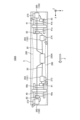
- FIG. 2 is a diagram showing a conventional mounting example shown as a comparative example.
- the traveling direction F is the +X-axis direction
- the horizontal direction orthogonal to the traveling direction F is the Y-axis direction
- the traveling direction F is The vertically upward direction perpendicular to the traveling direction F is defined as the +Z axis direction
- the vertically downward direction perpendicular to the traveling direction F is defined as the -Z axis direction.
- the Y-axis direction may be referred to as a "first direction.”
- FIG. 2 shows an example of mounting the above-mentioned trolley control system, in which two electric motors (not shown) are installed in each of the cart 40 on the front side and the cart 41 on the rear side with respect to the traveling direction F. It is installed.
- the housing 250 is equipped with a control device 251 that controls the two electric motors of the truck 40 and a control device 252 that controls the two electric motors of the truck 41.
- a cooler 253 for cooling the inverter provided in the control device 251 and a cooler 254 for cooling the inverter provided in the control device 252 are provided on the side surface of the case 250. It is attached so as to protrude in the Y-axis direction.
- FIG. 2 does not show any underfloor equipment other than the casing 250, in reality, various underfloor equipment necessary for the operation of the electric vehicle 150 are installed. Although the vehicle length of one electric car 150 is about 20 m, it is necessary to secure space for mounting various underfloor devices, and the length of the casing 250 in the vehicle longitudinal direction is less than 2 m at the longest.
- the conventional electric vehicle drive system has a configuration in which two coolers 253 and 254 are arranged close to each other in series along the traveling direction F of the electric vehicle 150.
- the inverter is cooled by the cooler 253 located on the windward side of the traveling wind, so that the traveling wind is efficiently taken into the cooler 253. This makes it easier to cool down.
- the two coolers 253 and 254 are close to each other, making it difficult for the traveling wind to be taken in by the cooler 254 on the leeward side.
- Patent Document 1 employs a structure in which a wind guide is provided to guide the traveling wind to the cooler on the leeward side, but this poses a problem in that the control device becomes larger and the manufacturing cost increases.
- FIG. 3 is a first diagram illustrating a first mounting example of the electric vehicle drive system according to the first embodiment.
- FIG. 4 is a second diagram illustrating a first mounting example of the electric vehicle drive system according to the first embodiment.
- FIG. 3 is a view of the electric vehicle 150A viewed from the side toward the negative direction of the Y-axis.
- FIG. 4 is a perspective view of the underfloor of the electric car 150A viewed from the floor surface of the electric car 150A toward the negative direction of the Z-axis.
- FIGS. 3 and 4 show examples of mounting the bogie control system, and the number of control devices is "2" per vehicle.
- control device 120 the other control device will be described as "control device 121.”
- the components of the electric vehicle drive system 200 are distributed and arranged under the floor of the electric vehicle 150A.
- the housing 250A that accommodates the switch 10 and the reactor 11 is arranged in the central part under the floor.
- the casing 260 that houses the control device 120 is located away from the central part under the floor and near the bogie 40 located in front of the electric vehicle 150A in the traveling direction F, specifically, It is located behind and to the left of 40.
- the casing 261 that houses the control device 121 is located away from the central part under the floor and near the trolley 41 located at the rear of the electric vehicle 150A in the traveling direction F, specifically, with respect to the traveling direction F. It is arranged in front of the truck 41 and on the right side.
- a cooler 270 for cooling the two inverters 60 included in the control device 120 is attached to the housing 260 so as to protrude in the +Y-axis direction from the side surface of the housing 260. Furthermore, a cooler 271 for cooling the two inverters 60 included in the control device 121 is attached to the casing 261 so as to protrude in the -Y-axis direction from the side surface of the casing 261.
- the truck 40 is equipped with electric motors 80 and 81, each of which is connected to the control device 120.
- the electric motor 80 drives the front axle 40a of the truck 40 in the traveling direction F
- the electric motor 81 drives the rear axle 40b of the truck 40 in the traveling direction F.
- the truck 41 is equipped with electric motors 82 and 83, each of which is connected to the control device 121.
- the electric motor 82 drives the front axle 41a of the truck 41 in the traveling direction F
- the electric motor 83 drives the rear axle 41b of the truck 41 in the traveling direction F.
- the trolley 40 may be referred to as a "first trolley” and the trolley 41 may be referred to as a "second trolley.”
- the control device 120 may be referred to as a "first control device” and the control device 121 may be referred to as a "second control device.”
- the cooler 270 located on the windward side of the traveling wind and the cooler 271 located on the leeward side of the traveling wind are arranged with a sufficient distance from each other. Therefore, it can be said that there are no nearby heating elements. Thereby, in the configurations of FIGS. 3 and 4, the difference between the cooling condition of the cooler 271 located on the leeward side and the cooling condition of the cooler 270 located on the windward side can be reduced. Thereby, in the configurations of FIGS. 3 and 4, it is possible to avoid increasing the size of the control devices 120, 121 and increasing the manufacturing cost of the control devices 120, 121.
- an rigging limit line 280 is shown by a dashed-dotted line with respect to the vehicle width of the vehicle 5 of the electric vehicle 150A.
- the rigging limit line 280 means the boundary line on the vehicle width side of the mounting area for the underfloor cargo. In other words, it is not possible for the underfloor cargo to be mounted so as to protrude outside the rigging limit line 280.
- the rigging limit line 280 is widest at the positions of the bogies 40 and 41 and narrowest at the center under the floor with respect to the vehicle width of the vehicle 5.
- the configuration of Form 1 has a configuration that allows the wind to be taken in more easily when the vehicle is running. Accordingly, it can be said that the configurations shown in FIGS. 3 and 4 are configured to improve the cooling performance of the coolers 270 and 271 compared to the prior art configuration shown in FIG. Accordingly, with the configurations shown in FIGS. 3 and 4, the control devices 120 and 121 can be arranged so as to enable efficient cooling.
- FIG. 5 is a diagram for explaining a second mounting example of the electric vehicle drive system according to the first embodiment.
- a casing 260 housing the control device 120 and a casing 261 housing the control device 121 are placed at opposite positions, that is, positions that are rotationally symmetrical when viewed from the center of the underfloor.
- the casing 260 accommodating the control device 120 remains as is, and the casing 261 accommodating the control device 121 is moved in the same line as the casing 260, that is, along the traveling direction F.
- 260 and the housing 261 are arranged in series.
- FIG. 6 is a diagram for explaining a third mounting example of the electric vehicle drive system according to the first embodiment.
- the components of the electric vehicle drive system 200 are distributed and arranged under the floor of the electric vehicle 150A.
- the housing 250A that accommodates the switch 10 and the reactor 11 is arranged in the central part under the floor.
- the casing 262 that houses the control device 100 is located near the bogie 40 located in front of the electric vehicle 150A in the traveling direction F, specifically, in front of the bogie 40 and on the right side with respect to the traveling direction F. It is located.
- the casing 263 that houses the control device 101 is located near the bogie 40 located in front of the electric vehicle 150A in the traveling direction F, specifically, at the rear and left side of the bogie 40 with respect to the traveling direction F. It is located.
- the casing 264 that houses the control device 102 is located near the bogie 41 located behind the electric vehicle 150A in the traveling direction F, specifically, in front of the bogie 41 and on the right side with respect to the traveling direction F. It is located in Furthermore, the casing 265 that houses the control device 103 is located near the bogie 41 located at the rear of the electric vehicle 150A in the traveling direction F, specifically, at the rear and left side of the bogie 41 with respect to the traveling direction F. It is located.
- each of the two control devices 100 and 101 that individually control the two electric motors 80 and 81 mounted on the bogie 40, which is the first bogie may be referred to as a "first control device.” be.
- each of the two control devices 102 and 103 that individually controls the two electric motors 82 and 83 mounted on the second truck 41 may be referred to as a "second control device.”
- a cooler 272 for cooling the inverter 60 included in the control device 100 is attached to the casing 262 so as to protrude in the ⁇ Y-axis direction from the side surface of the casing 262. Furthermore, a cooler 273 for cooling the inverter 60 included in the control device 101 is attached to the housing 263 so as to protrude in the +Y-axis direction from the side surface of the housing 263. Furthermore, a cooler 274 for cooling the inverter 60 included in the control device 102 is attached to the casing 264 so as to protrude in the ⁇ Y-axis direction from the side surface of the casing 264. Furthermore, a cooler 275 for cooling the inverter 60 included in the control device 103 is attached to the housing 265 so as to protrude in the +Y-axis direction from the side surface of the housing 265.
- the cooler 272 located on the windward side of the traveling wind and the cooler 273 located on the leeward side of the traveling wind are separated by at least the length of the bogie 40. Therefore, it can be said that there are no nearby heating elements. Thereby, in the configuration of FIG. 6, the difference between the cooling condition of the cooler 272 located on the windward side and the cooling condition of the cooler 273 located on the leeward side can be reduced. This relationship is also the same between the coolers 274 and 275 in the truck 41. As a result, in the configuration of FIG. 6, it is possible to avoid increasing the size of the control devices 100 to 103 and increasing the manufacturing cost of the control devices 100 to 103.
- the casings 262 to 265 that house the control devices 100 to 103 can be placed near the carts 40 and 41, where the width between the rigging limit line 280 is wide.
- the control devices 100 to 103 can be arranged to enable efficient cooling even in an individual control system configuration.
- FIG. 7 is a diagram for explaining a fourth mounting example of the electric vehicle drive system according to the first embodiment.
- housings 262, 263 housing the control devices 100, 101 are arranged at opposite poles, that is, positions diagonally on the truck 40; 265 is placed at the opposite pole, that is, at a diagonal position on the trolley 41, and the housing 263 housing the control device 101 and the housing 264 housing the control device 102 are placed at opposite poles when viewed from the central part under the floor. It was placed in the position of On the other hand, in FIG. 7, the housings 263 housing the control device 101 and the housing 263 housing the control device 101 and the control device 102 are arranged so as to be lined up in the traveling direction F.
- FIG. 8 is a diagram showing the results of a first verification test for explaining the influence of obstacles on the running wind toward the cooler.
- FIG. 9 is a diagram showing the results of a second verification test for explaining the influence of obstacles on the running wind toward the cooler.
- FIG. 8 schematically shows the test environment for the first verification test.
- an obstacle 170 is placed on the windward side of the cooling air
- an aluminum cooler 160 is placed on the leeward side of the cooling air.
- FIG. 8 is a plan view, and the length of the obstacle 170 in the height direction and the length of the aluminum cooler 160 in the height direction are made equal.
- the cooling air is blown by a blower (not shown).
- the position of the side portion 162 in the aluminum cooler 160 is regulated by a position regulating portion 180.
- the side portion 162 is a portion located on the tip side of the aluminum cooler 160 along the direction of the cooling air.
- the position of the side 162 along the direction of the cooling air is regulated so as to match the position of the side 172 of the obstacle 170 along the direction of the cooling air.
- the width of the aluminum cooler 160 that is, the length of the aluminum cooler 160 in the direction perpendicular to the cooling air is d.
- the position d/2 from the position regulating part 180 on the blown surface of the aluminum cooler 160 is defined as the "front wind speed measurement point”
- the position d/2 from the side part 162 of the aluminum cooler 160 is defined as the "side surface wind speed measurement point”.
- Windd speed measurement point Then, using the "distance” that is the shortest distance between the obstacle 170 and the aluminum cooler 160 as a parameter, wind speed was measured at the front wind speed measurement point and the side wind speed measurement point.
- the test results of the first verification test are shown in tabular form.
- the second verification test will be explained.
- the distance between the aluminum cooler 160 and the obstacle 170 was 1.5 m, and the front wind speed measurement point was located at I'm trying to match that. That is, the aluminum cooler 160 in FIG. 9 is restricted to a position protruding by d/2 in a direction perpendicular to the direction of the cooling air, compared to that in FIG. 8. In this state, the wind speed at the front wind speed measurement point was measured when the obstacle 170 was present and when the obstacle 170 was not present.
- the length of the casing 250 to which the two coolers 253 and 254 are attached in the longitudinal direction of the vehicle is less than 2 m at most. Therefore, the distance between the two coolers 253 and 254 is considered to be approximately 1.5 m or less than 1.5 m. Therefore, the idea of the prior art that the cooling performance of the cooler 254 located on the leeward side of the traveling wind is influenced by the cooler 253 located on the windward side of the traveling wind is consistent with the results of the above verification test. There is.
- the cooler 270 located on the windward side and the cooler 271 located on the leeward side are arranged with a sufficient distance apart. Since the coolers 270 and 271 are arranged close to the carts 40 and 41 with a wide width between the rigging limit lines 280, they can be arranged in positions where they are hardly affected by obstacles. Become.
- the coolers 272, 274 located on the windward side and the coolers 273, 275 located on the leeward side are arranged with a sufficient distance from each other for each trolley 40, 41. Since the coolers 272 to 275 are arranged close to the trolley 40 or 41 with a wide width between the rigging limit lines 280, they can be arranged in positions where they are hardly affected by obstacles. becomes.
- the electric vehicle drive system includes a plurality of control devices that control at least one of the four electric motors that drive the four axles of the two bogies of the electric vehicle.
- Each of the control devices includes an inverter that supplies power to at least one electric motor, and a control section that controls the inverter.
- the inverter is housed in a housing together with a control unit, each housing houses at least one control device, and each housing cools the inverter by using running air generated by the running of the electric vehicle.
- a cooler is installed.
- the plurality of control devices are distributed and arranged near the first truck located in front of the electric vehicle in the direction of travel and near the second truck located at the rear in the direction of travel of the electric vehicle.
- the cooler located on the leeward side can be arranged with a sufficient distance from the cooler located on the windward side.
- the cooler located on the leeward side and the cooler located on the windward side have the first and second coolers having a width between the rigging limit lines wider than the center part under the floor. Since it is placed near the trolley, it can be placed in a position where it is hardly affected by obstacles.
- the plurality of control devices include one first control device that controls two electric motors mounted on a first cart, and one control device that controls two electric motors mounted on a second cart.
- the present invention is applicable to a bogie control type electric vehicle drive system comprising a second control device.
- a housing that accommodates the first control device is placed behind the first truck with respect to the traveling direction, and a housing that houses the second control device is located behind the first truck with respect to the traveling direction. It can be arranged in front of the second truck.
- the plurality of control devices separately control two electric motors mounted on the first trolley, and two electric motors mounted on the second trolley. It is applicable to an electric vehicle drive system of an individual control type that includes two second control devices that are individually controlled.
- a housing housing one of the two first control devices is arranged in front of the first truck with respect to the traveling direction, and the other of the two first control devices.
- the housing that accommodates the first truck is located behind the first truck with respect to the traveling direction
- the housing that accommodates one of the two second control devices is located behind the second truck with respect to the traveling direction.
- the casing disposed at the front and accommodating the other of the two second control devices may be disposed at the rear of the second trolley in the traveling direction.
- the two casings housing one and the other of the two first control devices are arranged behind the first trolley with respect to the traveling direction, and one of the two second control devices
- the two housings accommodating the one and the other may be arranged in front of the second cart in the traveling direction.
- the plurality of coolers housing the first and second control devices protrude in the first direction perpendicular to both the traveling direction of the electric car and the vertical direction of the electric car. It can be configured to be attached to the body.
- FIG. 10 is a diagram for explaining an example of mounting the electric vehicle drive system according to the second embodiment.
- FIG. 10 is a diagram of the electric vehicle 150B according to the second embodiment viewed from the side toward the negative direction of the Y-axis.
- FIG. 10 shows an example of mounting the trolley control system. Note that the same or equivalent components as in FIG. 3 are given the same reference numerals.
- the difference between the electric car 150B according to the second embodiment shown in FIG. 10 and the electric car 150A according to the first embodiment shown in FIG. 3 is the mounting position and protrusion direction of the coolers 270 and 271.
- the coolers 270 and 271 are attached to the side surface of the casing 260 or 261 so as to protrude in the +Y-axis direction or the -Y-axis direction.
- the coolers 270 and 271 are attached to the lower surface of the housing 260 or the housing 261 so as to protrude in the ⁇ Z-axis direction.
- the cooler 270 located on the windward side of the traveling wind and the cooler 271 located on the leeward side of the traveling wind are arranged with a sufficient distance between them, so the configuration of FIG. 3 The same effect can be obtained.
- the configuration shown in FIG. 10 is preferable to the configuration shown in FIG. 3. There may be cases where it is easier to design. Therefore, the configuration of the second embodiment may also be adopted in the mounting examples shown in FIGS. 5 to 7.
Landscapes
- Engineering & Computer Science (AREA)
- Power Engineering (AREA)
- Transportation (AREA)
- Mechanical Engineering (AREA)
- Life Sciences & Earth Sciences (AREA)
- Sustainable Development (AREA)
- Sustainable Energy (AREA)
- Electric Propulsion And Braking For Vehicles (AREA)
Priority Applications (5)
| Application Number | Priority Date | Filing Date | Title |
|---|---|---|---|
| US18/875,385 US20250368053A1 (en) | 2022-08-01 | 2022-08-01 | Electric vehicle drive system |
| DE112022007621.6T DE112022007621T5 (de) | 2022-08-01 | 2022-08-01 | Elektrofahrzeug-antriebssystem |
| PCT/JP2022/029508 WO2024028948A1 (ja) | 2022-08-01 | 2022-08-01 | 電気車駆動システム |
| CN202290000955.5U CN223735852U (zh) | 2022-08-01 | 2022-08-01 | 电车驱动系统 |
| JP2024538542A JP7580675B2 (ja) | 2022-08-01 | 2022-08-01 | 電気車駆動システム |
Applications Claiming Priority (1)
| Application Number | Priority Date | Filing Date | Title |
|---|---|---|---|
| PCT/JP2022/029508 WO2024028948A1 (ja) | 2022-08-01 | 2022-08-01 | 電気車駆動システム |
Publications (1)
| Publication Number | Publication Date |
|---|---|
| WO2024028948A1 true WO2024028948A1 (ja) | 2024-02-08 |
Family
ID=89848655
Family Applications (1)
| Application Number | Title | Priority Date | Filing Date |
|---|---|---|---|
| PCT/JP2022/029508 Ceased WO2024028948A1 (ja) | 2022-08-01 | 2022-08-01 | 電気車駆動システム |
Country Status (5)
| Country | Link |
|---|---|
| US (1) | US20250368053A1 (https=) |
| JP (1) | JP7580675B2 (https=) |
| CN (1) | CN223735852U (https=) |
| DE (1) | DE112022007621T5 (https=) |
| WO (1) | WO2024028948A1 (https=) |
Citations (3)
| Publication number | Priority date | Publication date | Assignee | Title |
|---|---|---|---|---|
| JPH04185206A (ja) * | 1990-11-19 | 1992-07-02 | Toshiba Corp | 電気車駆動電動機の制御装置 |
| JP2000127963A (ja) * | 1998-10-20 | 2000-05-09 | Toshiba Corp | 電気車の空転制御装置 |
| JP2006271029A (ja) * | 2005-03-22 | 2006-10-05 | Toshiba Corp | 電気車駆動装置 |
Family Cites Families (2)
| Publication number | Priority date | Publication date | Assignee | Title |
|---|---|---|---|---|
| JP2005053330A (ja) | 2003-08-04 | 2005-03-03 | Toshiba Corp | 鉄道車両用電力変換装置 |
| DE112020007275T5 (de) | 2020-06-02 | 2023-05-25 | Mitsubishi Electric Corporation | Elektrofahrzeug-steuervorrichtung |
-
2022
- 2022-08-01 JP JP2024538542A patent/JP7580675B2/ja active Active
- 2022-08-01 WO PCT/JP2022/029508 patent/WO2024028948A1/ja not_active Ceased
- 2022-08-01 DE DE112022007621.6T patent/DE112022007621T5/de active Pending
- 2022-08-01 US US18/875,385 patent/US20250368053A1/en active Pending
- 2022-08-01 CN CN202290000955.5U patent/CN223735852U/zh active Active
Patent Citations (3)
| Publication number | Priority date | Publication date | Assignee | Title |
|---|---|---|---|---|
| JPH04185206A (ja) * | 1990-11-19 | 1992-07-02 | Toshiba Corp | 電気車駆動電動機の制御装置 |
| JP2000127963A (ja) * | 1998-10-20 | 2000-05-09 | Toshiba Corp | 電気車の空転制御装置 |
| JP2006271029A (ja) * | 2005-03-22 | 2006-10-05 | Toshiba Corp | 電気車駆動装置 |
Also Published As
| Publication number | Publication date |
|---|---|
| JP7580675B2 (ja) | 2024-11-11 |
| JPWO2024028948A1 (https=) | 2024-02-08 |
| DE112022007621T5 (de) | 2025-05-22 |
| US20250368053A1 (en) | 2025-12-04 |
| CN223735852U (zh) | 2025-12-30 |
Similar Documents
| Publication | Publication Date | Title |
|---|---|---|
| JP4987495B2 (ja) | 鉄道車両駆動用モータドライブシステム | |
| JP4243308B2 (ja) | 電力変換装置 | |
| EP3664274B1 (en) | Power conversion device and vehicle equipped with power conversion device | |
| JP6812317B2 (ja) | 電力変換装置および電力変換装置を搭載した車両 | |
| CN110710094B (zh) | 电力变换装置 | |
| EP3745579B1 (en) | Power conversion device and electric railroad vehicle equipped with power conversion device | |
| JP2010284049A (ja) | 鉄道車両用の電力変換装置 | |
| US10615707B2 (en) | Inverter control device | |
| CN106169835B (zh) | 车辆用驱动装置 | |
| WO2021245800A1 (ja) | 電気車制御装置 | |
| WO2024028948A1 (ja) | 電気車駆動システム | |
| JP6827477B2 (ja) | 電動機動力システム及び電気車 | |
| JP6715160B2 (ja) | 電動機動力システム及び電気車 | |
| JP7049533B2 (ja) | 電力変換装置 | |
| CN210724586U (zh) | 一种中低速磁悬浮车牵引变流器 | |
| EP4509380A1 (en) | Electronic apparatus | |
| JP7483186B2 (ja) | 電力変換装置 | |
| CN112172844B (zh) | 一种牵引电机及轨道车辆 | |
| CN206595905U (zh) | 电气轨道车辆上基于脉宽调制的车载电源变流器 | |
| CN206442306U (zh) | 电气轨道车辆上的功率模块 | |
| JP6479417B2 (ja) | 電気車制御装置 | |
| JP2006254656A (ja) | 鉄道車両用の電力変換装置 | |
| RU2411626C1 (ru) | Устройство преобразования электроэнергии | |
| CN107150594A (zh) | 电车控制装置 | |
| WO2016157532A1 (ja) | 電力変換装置 |
Legal Events
| Date | Code | Title | Description |
|---|---|---|---|
| 121 | Ep: the epo has been informed by wipo that ep was designated in this application |
Ref document number: 22953938 Country of ref document: EP Kind code of ref document: A1 |
|
| ENP | Entry into the national phase |
Ref document number: 2024538542 Country of ref document: JP Kind code of ref document: A |
|
| WWE | Wipo information: entry into national phase |
Ref document number: 202447097367 Country of ref document: IN |
|
| WWE | Wipo information: entry into national phase |
Ref document number: 18875385 Country of ref document: US |
|
| WWE | Wipo information: entry into national phase |
Ref document number: 112022007621 Country of ref document: DE |
|
| WWP | Wipo information: published in national office |
Ref document number: 112022007621 Country of ref document: DE |
|
| 122 | Ep: pct application non-entry in european phase |
Ref document number: 22953938 Country of ref document: EP Kind code of ref document: A1 |
|
| WWP | Wipo information: published in national office |
Ref document number: 18875385 Country of ref document: US |