WO2024024255A1 - タイヤの製造方法及びタイヤ - Google Patents
タイヤの製造方法及びタイヤ Download PDFInfo
- Publication number
- WO2024024255A1 WO2024024255A1 PCT/JP2023/019789 JP2023019789W WO2024024255A1 WO 2024024255 A1 WO2024024255 A1 WO 2024024255A1 JP 2023019789 W JP2023019789 W JP 2023019789W WO 2024024255 A1 WO2024024255 A1 WO 2024024255A1
- Authority
- WO
- WIPO (PCT)
- Prior art keywords
- tire
- electronic device
- mold
- manufacturing
- upper mold
- Prior art date
- Legal status (The legal status is an assumption and is not a legal conclusion. Google has not performed a legal analysis and makes no representation as to the accuracy of the status listed.)
- Ceased
Links
Images


Classifications
-
- B—PERFORMING OPERATIONS; TRANSPORTING
- B60—VEHICLES IN GENERAL
- B60C—VEHICLE TYRES; TYRE INFLATION; TYRE CHANGING; CONNECTING VALVES TO INFLATABLE ELASTIC BODIES IN GENERAL; DEVICES OR ARRANGEMENTS RELATED TO TYRES
- B60C19/00—Tyre parts or constructions not otherwise provided for
-
- B—PERFORMING OPERATIONS; TRANSPORTING
- B29—WORKING OF PLASTICS; WORKING OF SUBSTANCES IN A PLASTIC STATE IN GENERAL
- B29C—SHAPING OR JOINING OF PLASTICS; SHAPING OF MATERIAL IN A PLASTIC STATE, NOT OTHERWISE PROVIDED FOR; AFTER-TREATMENT OF THE SHAPED PRODUCTS, e.g. REPAIRING
- B29C33/00—Moulds or cores; Details thereof or accessories therefor
- B29C33/02—Moulds or cores; Details thereof or accessories therefor with incorporated heating or cooling means
-
- B—PERFORMING OPERATIONS; TRANSPORTING
- B29—WORKING OF PLASTICS; WORKING OF SUBSTANCES IN A PLASTIC STATE IN GENERAL
- B29C—SHAPING OR JOINING OF PLASTICS; SHAPING OF MATERIAL IN A PLASTIC STATE, NOT OTHERWISE PROVIDED FOR; AFTER-TREATMENT OF THE SHAPED PRODUCTS, e.g. REPAIRING
- B29C33/00—Moulds or cores; Details thereof or accessories therefor
- B29C33/12—Moulds or cores; Details thereof or accessories therefor with incorporated means for positioning inserts, e.g. labels
-
- B—PERFORMING OPERATIONS; TRANSPORTING
- B29—WORKING OF PLASTICS; WORKING OF SUBSTANCES IN A PLASTIC STATE IN GENERAL
- B29C—SHAPING OR JOINING OF PLASTICS; SHAPING OF MATERIAL IN A PLASTIC STATE, NOT OTHERWISE PROVIDED FOR; AFTER-TREATMENT OF THE SHAPED PRODUCTS, e.g. REPAIRING
- B29C35/00—Heating, cooling or curing, e.g. crosslinking or vulcanising; Apparatus therefor
- B29C35/02—Heating or curing, e.g. crosslinking or vulcanizing during moulding, e.g. in a mould
-
- B—PERFORMING OPERATIONS; TRANSPORTING
- B29—WORKING OF PLASTICS; WORKING OF SUBSTANCES IN A PLASTIC STATE IN GENERAL
- B29D—PRODUCING PARTICULAR ARTICLES FROM PLASTICS OR FROM SUBSTANCES IN A PLASTIC STATE
- B29D30/00—Producing pneumatic or solid tyres or parts thereof
- B29D30/0061—Accessories, details or auxiliary operations not otherwise provided for
-
- B—PERFORMING OPERATIONS; TRANSPORTING
- B29—WORKING OF PLASTICS; WORKING OF SUBSTANCES IN A PLASTIC STATE IN GENERAL
- B29D—PRODUCING PARTICULAR ARTICLES FROM PLASTICS OR FROM SUBSTANCES IN A PLASTIC STATE
- B29D30/00—Producing pneumatic or solid tyres or parts thereof
- B29D30/06—Pneumatic tyres or parts thereof (e.g. produced by casting, moulding, compression moulding, injection moulding, centrifugal casting)
- B29D30/0601—Vulcanising tyres; Vulcanising presses for tyres
- B29D30/0606—Vulcanising moulds not integral with vulcanising presses
-
- B—PERFORMING OPERATIONS; TRANSPORTING
- B29—WORKING OF PLASTICS; WORKING OF SUBSTANCES IN A PLASTIC STATE IN GENERAL
- B29D—PRODUCING PARTICULAR ARTICLES FROM PLASTICS OR FROM SUBSTANCES IN A PLASTIC STATE
- B29D30/00—Producing pneumatic or solid tyres or parts thereof
- B29D30/06—Pneumatic tyres or parts thereof (e.g. produced by casting, moulding, compression moulding, injection moulding, centrifugal casting)
- B29D30/0681—Parts of pneumatic tyres; accessories, auxiliary operations
-
- B—PERFORMING OPERATIONS; TRANSPORTING
- B60—VEHICLES IN GENERAL
- B60C—VEHICLE TYRES; TYRE INFLATION; TYRE CHANGING; CONNECTING VALVES TO INFLATABLE ELASTIC BODIES IN GENERAL; DEVICES OR ARRANGEMENTS RELATED TO TYRES
- B60C19/00—Tyre parts or constructions not otherwise provided for
- B60C2019/004—Tyre sensors other than for detecting tyre pressure
Definitions
- the present invention relates to a tire manufacturing method and a tire.
- This application claims priority based on Japanese Patent Application No. 2022-118281 filed in Japan on July 25, 2022, and the entire content thereof is incorporated herein by reference.
- Patent Document 1 discloses a pneumatic tire in which a film-like electronic device is mounted on the tire surface of the tire side portion.
- an object of the present invention to provide a tire manufacturing method and a tire, in which an electronic device can be attached to the tire side portion near the outer surface of the tire using a simple method.
- the method for manufacturing a tire of the present invention includes: A method for manufacturing a tire for obtaining a tire with an electronic device attached to the tire side part, the method comprising: A lower mold and an upper mold are used as molds for curing green tires.
- the tire of the present invention includes: It is characterized by being manufactured by the above tire manufacturing method. According to the tire according to the present invention, an electronic device can be attached to the tire side portion near the outer surface of the tire by a simple method during tire manufacture.
- FIG. 1 is a schematic cross-sectional view in the tire width direction of a tire according to an embodiment of the present invention.
- FIG. 1 is a diagram showing an example of an electronic device or an electronic device laminate including the electronic device, which can be used in a tire according to an embodiment of the present invention and a method for manufacturing a tire according to an embodiment of the present invention.
- a) is a plan view schematically showing the electronic device
- (b) is a perspective view schematically showing an example of the electronic device stack
- (c) is a plan view schematically showing an example of the electronic device stack.
- 1 is a schematic longitudinal cross-sectional view of an electronic device; FIG. BRIEF DESCRIPTION OF THE DRAWINGS FIG.
- FIG. 1 is a schematic cross-sectional view in the tire width direction showing an example of a mold and a raw tire that can be used in the tire manufacturing method according to an embodiment of the present invention.
- FIG. 4 is an enlarged front sectional view showing the vicinity of the serial plate held by the upper mold in FIG. 3 together with the electronic device before being fixed to the serial plate.
- 5 is a schematic view taken along the line XX in FIG. 4.
- FIG. (a) to (d) respectively show a serial plate, an elastic member, and an electronic device as members separate from the mold, which are arranged in the electronic device arrangement step in the tire manufacturing method according to an embodiment of the present invention.
- 5A and 5B are drawings for explaining different examples of the configuration of the device.
- a drawing for explaining an example of the arrangement relationship on the mold circumference of electronic devices arranged on the lower mold side and the upper mold side in the electronic device arrangement step in the tire manufacturing method according to an embodiment of the present invention It is. (a) to (d) respectively show a mold for a serial plate and an electronic device to be placed on the lower mold side or the upper mold side in the electronic device placement step in the tire manufacturing method according to an embodiment of the present invention. It is a drawing for explaining different examples of arrangement relationships on the circumference.
- the method for manufacturing a tire according to the present invention and the tire according to the present invention can be suitably used as a method for manufacturing any type of tire and as any type of tire, such as tires for passenger cars, tires for trucks and buses, tires for construction and It can be suitably used as a tire for mining vehicles, etc., or a manufacturing method thereof, and in particular, it can be suitably used as a tire for construction/mining vehicles, or a manufacturing method thereof.
- tire circumferential direction refers to the direction in which the tire rotates around the tire's rotation axis
- tire radial direction refers to the direction perpendicular to the tire's rotation axis
- tire width direction refers to the direction in which the tire rotates around the tire's rotation axis.
- Direction refers to a direction parallel to the axis of rotation of the tire.
- the tire circumferential direction is indicated by the symbol “CD”
- the tire radial direction is indicated by the symbol “RD”
- the tire width direction is indicated by the symbol “WD”.
- the side closer to the rotational axis of the tire along the tire radial direction is referred to as the “tire radial inner side”
- the side farther from the tire rotational axis along the tire radial direction is referred to as the “tire radial outer side”. It is called.
- the side closer to the tire equatorial plane CL along the tire width direction is referred to as the "inner side in the tire width direction”
- the side farther from the tire equatorial plane CL along the tire width direction is referred to as the “outer side in the tire width direction”. It is called.
- the term “inner surface of the tire” refers to the surface of the tire that faces the inner cavity of the tire
- the term “outer surface of the tire” refers to the surface of the tire that faces the outside of the tire.
- tires circumferential direction and codes such as “CD” are used not only for tires after vulcanization (i.e., finished tires) but also for raw tires before vulcanization. shall be used. Furthermore, in this specification, terms such as “mold circumferential direction” and codes such as “CD” may be used with the same meaning as above with respect to a mold for vulcanizing a green tire.
- FIG. 1 is a drawing for explaining a tire 10 according to an embodiment of the present invention, and is a schematic cross-sectional view of the tire 10 in the tire width direction. Since the tire 10 according to one embodiment of the present invention is a tire manufactured by the tire manufacturing method according to any embodiment of the present invention, which will be described later, the effects obtained by the tire manufacturing method will be described later.
- the tire 10 when manufacturing the tire 10, an electronic device can be attached near the outer surface of the tire at the tire side portion by a simple method.
- the tire 10 according to the embodiment of the present invention may be configured as a tire of any type and/or any size.
- the tire 10 of the present embodiment, and by extension, the tire 10 manufactured by the tire manufacturing method according to an embodiment of the present invention described below is a tire in which the nominal rim diameter of the applicable rim is 20 inches or more. may be configured. Examples of the nominal rim diameter of the applicable rim are 20 inches or more, such as 25 inches, 29 inches, 33 inches, 35 inches, 49 inches, 51 inches, 57 inches, 63 inches, etc. can be mentioned.
- the nominal rim diameter of the rim to which the tire 10 is applied is 20 inches or more
- problems may arise in communication performance, for example.
- the "nominal rim diameter of the applicable rim” refers to the inner diameter of the tire and the rim diameter of the applicable rim. refers to the name (in inches) of the rim diameter of the applicable rim in the tire size display generally displayed on the sidewall of the tire, that is, the rim diameter of the applicable rim expressed in inches. For example, if the tire size is "29.5R25”, the nominal rim diameter is “25 inches”, and if the tire size is "18.00R33", the nominal rim diameter is "33 inches”. If the tire size is "46/90R57”, the nominal rim diameter is “57 inches”, and if the tire size is "59/80R63", the nominal rim diameter is "63 inches”.
- appcable rim refers to an industrial standard that is valid in the region where tires are produced and used, such as JATMA YEAR BOOK of JATMA (Japan Automobile Tire Association) in Japan, and ETRTO (The STANDARDS MANUAL of European Tire and Rim Technical Organization, TRA (The Tire and Rim Association, In the United States) c.) Standard rims (ETRTO STANDARDS) in the applicable sizes listed in the YEAR BOOK etc. or to be listed in the future.
- MANUAL In MANUAL, it refers to Measuring Rim, and in TRA's YEAR BOOK, it refers to Design Rim), but in the case of sizes not listed in these industrial standards, it refers to a rim with a width corresponding to the bead width of a pneumatic tire.
- Applicable rims include not only current sizes but also sizes that will be listed in the aforementioned industrial standards in the future. Examples of “sizes to be described in the future” include sizes described as "FUTURE DEVELOPMENTS" in the 2013 edition of ETRTO.
- the tire 10 is a pneumatic tire, and has a bead portion 1, a sidewall portion 2, and a tread portion 3, as shown in FIG.
- the bead portion 1 is a portion configured to contact the rim on the inner side in the tire radial direction and the outer side in the tire width direction when the tire 10 is mounted on the rim.
- the tread portion 3 is a portion of the tire 10 in the tire width direction between a pair of tread ends.
- the sidewall portion 2 is a portion between the pair of bead portions 1 and the tread portion 3.
- the sidewall portion 2 and bead portion 1 of the tire 10 may be collectively referred to as a tire side portion 8.
- the sidewall portion 2 refers to a portion radially inward of the tire at least from a belt 7, which will be described later, and a portion radially outside the bead portion 1 of the tire.
- the tire 10 of this embodiment includes a pair of bead portions 1 having a bead core 11, and a toroid between the pair of bead portions 1 via a pair of sidewall portions 2 and a tread portion 3.
- a carcass 4 consisting of at least one (in the illustrated example, one) carcass ply extending in a shape, and a carcass 4 provided on the outside in the tire radial direction of the carcass 4 in the tread portion 3 (i.e., the crown portion of the carcass 4).
- a belt 7 consisting of at least one belt layer (six layers in the illustrated example) and an electronic device 6 attached to a tire side part 8 (more specifically, in this example, the sidewall part 2) It is equipped with. As shown in FIG.
- a serial 5 is stamped on the tire outer surface 10o side of the electronic device 6.
- the term “electronic device” refers to a device that includes electronic components and, for example, has a communication function with the outside.
- a portion of the tire 10 excluding the electronic device 6 or the electronic device laminate 60 described below is referred to as a "tire body”
- a portion of the tire 10 excluding the electronic device 6 or the electronic device laminate 60 described below is referred to as a "tire body”
- the portion excluding the device laminate 60 may be referred to as a "raw tire body.”
- each bead core 11 is embedded in the corresponding bead portion 1.
- the bead core 11 may include a plurality of bead wires whose peripheries are covered with rubber.
- the bead core 11 may be made of one bead wire.
- the bead wire is constructed of metal (eg steel).
- the bead wire may, for example, consist of monofilament or stranded wire.
- the bead wire may be made of organic fiber, carbon fiber, or the like.
- the cross-sectional shape of the bead core 11 in the tire width direction is a regular hexagonal shape. The shape may be circular, etc.
- the carcass 4 includes a carcass body portion located between the bead cores 11 of a pair of bead portions 1, and a carcass body portion located between the bead cores 11 of a pair of bead portions 1, and a carcass body portion located from the inner side in the tire width direction from both ends of the carcass body portion around each bead core 11.
- the carcass 4 does not need to include a carcass folded part.
- Each carcass ply constituting the carcass 4 includes one or more carcass cords and a covering rubber that covers the carcass cords.
- the carcass cord can be made of monofilament or stranded wire, for example.
- the carcass cord is made of steel. Since the carcass cord is made of steel, sufficient strength can be obtained even if the carcass has a simple radial structure, for example with a large tire. Moreover, in this example, the carcass 4 has a radial structure. That is, each carcass cord included in the carcass ply of the carcass 4 extends substantially along the tire width direction (i.e., when viewed from outside in the tire radial direction of the tread portion 3, substantially along the tire width direction). (without inclination at an angle of 0°). However, the carcass cord may be made of organic fibers such as polyester, nylon, rayon, and aramid. Moreover, the carcass 4 may have a bias structure.
- each belt layer constituting the belt 7 includes one or more belt cords and a covering rubber that covers the belt cords.
- the belt cord can be made of monofilament or stranded wire, for example.
- the belt cord may be made of metal (for example, steel), or may be made of organic fiber such as polyester, nylon, rayon, aramid, or the like.
- Serial 5 is an identification mark that expresses the tire's serial number, manufacturing date, manufacturer name, etc. using letters, numbers, symbols, figures, etc., and is used to easily identify the type of tire manufactured. It is something.
- the serial 5 is stamped on the tire 10 by, for example, a serial plate 50 that will be described later.
- the electronic device 6 is disposed near the tire outer surface 10o in the tire side portion 8.
- “near (the) outer surface of the tire” or “near (the) outer surface of the tire” refers to at least the carcass 4 (more specifically, in this example, the carcass folded part of the carcass 4). ) refers to the position on the outside in the tire width direction, and includes the position on the outer surface of the tire.
- the electronic device 6 may be embedded within the tire side portion 8 or may be attached on the tire outer surface 10o of the tire side portion 8. In the example of FIG. 1, the electronic device 6 is embedded within the sidewall portion 2.
- the electronic device 6 may be attached to the tire side portion 8 of the tire 10 by itself (see FIG. 2(a)), or at least a portion of the surface of the electronic device 6 may be attached to the tire side portion 8 of the tire 10.
- the electronic device stack 60 (see FIGS. 2(b) to 2(c)) including the electronic device 6 and having the member 61 may be attached to the tire side portion 8 of the tire 10.
- the electronic device 6 may be used alone (see FIG. 2(a)) in the electronic device placement step in the tire manufacturing method according to an embodiment of the present invention, which will be described later, or the electronic device 6 may be used alone (see FIG. 2(a)), or It may also be used as a device stack 60 (see FIGS.
- the electronic device 6 when the electronic device 6 includes an elastic member 61 on at least a part of the surface of the electronic device 6, the durability and/or the adhesion to the tire body of the electronic device 6 can be improved. Can be done.
- the electronic device 6 is placed at a position where the depth of the tire side portion 8 from the tire outer surface 10o is 0.1 to 10.0 mm. In this case, the electronic device 6 is less susceptible to damage during tire running, and the durability of the electronic device 6 can be improved, and information on the electronic device 6 can be easily read from the outside. From the same viewpoint, it is more preferable that the electronic device 6 is disposed at a position where the depth of the tire side portion 8 from the tire outer surface 10o is 0.5 to 5.0 mm. Note that when the electronic device 6 is, for example, an RF tag as shown in any of FIGS.
- the surfaces on both sides in the thickness direction TD of the thin IC chip 6a (for example, in FIG. 2(a), the IC chip 6a is attached to the tire outer surface 10o side so that the front and back surfaces of the IC chip 6a are along the tire outer surface 10o (that is, so that both are substantially parallel).
- the center of the thickness direction TD may be arranged at the above depth position.
- tread rubber that forms a tread surface which is the tire outer surface 10o of the tread portion 3, is provided on the outside of the belt 7 in the tire radial direction in the tread portion 3.
- a tread pattern is formed on the tread surface.
- the tread pattern is a lug pattern in which lugs are defined in the tire circumferential direction by lug grooves, but the tread pattern is not particularly limited.
- side rubber forming the tire outer surface 10o of the tire side portion 8 is provided on the outside of the carcass 4 in the tire width direction in the tire side portion 8.
- the inner surface of the tire is composed of an inner liner (not particularly shown) having low air and/or gas permeability.
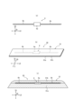
- FIG. 2 is a diagram showing an example of an electronic device or an electronic device laminate including the electronic device, which can be used in a tire according to an embodiment of the present invention and a method for manufacturing a tire according to an embodiment of the present invention.
- FIG. 2(a) is a plan view schematically showing an example of the electronic device
- FIG. 2(b) is a perspective view schematically showing an example of the electronic device stack
- FIG. 2(c) is a plan view schematically showing an example of the electronic device.
- FIG. 2 is a longitudinal sectional view of an electronic device schematically showing another example of the electronic device stack.
- the electronic device 6 includes an IC chip 6a having a storage unit, etc., and one or more (in the illustrated example, two) IC chips 6a that transmit and/or receive electromagnetic waves. It is an RF tag having an antenna 6b.
- the RF tag is generally also called an RFID (Radio Frequency Identification) tag.
- the antenna 6b is connected to the IC chip 6a and extends linearly, wavyly, or spirally (in the illustrated example, spirally).
- two antennas 6b extend in opposite directions from the IC chip 6a. However, the antenna 6b may extend only to one side from the IC chip 6a.
- the two antennas 6b have the same length in the long side direction LD of the IC chip 6a, which will be described later. However, the two antennas may have different lengths in the long side direction LD of the IC chip 6a.
- the IC chip 6a has a thin thin plate shape that is approximately rectangular in plan view (see FIG. 2(a)).
- the "thickness" of the IC chip 6a refers to a direction parallel to the long side of the IC chip 6a (hereinafter also referred to as "the long side direction of the IC chip (6a)") when viewed from above.
- a direction parallel to the direction along the short side of the IC chip (6a) in plan view (hereinafter also referred to as “the short side direction of the IC chip (6a)"), and a direction perpendicular to both SD (hereinafter referred to as “the short side direction of the IC chip (6a)”).
- the short side direction of the IC chip (6a) refers to the thickness of the TD.
- the long side direction LD of the IC chip (6a) is also the longitudinal direction of the electronic device (6)
- the short side direction SD of the IC chip (6a) is the short side direction of the electronic device (6).
- the thickness direction TD of the IC chip (6a) is also the thickness direction of the electronic device (6).
- the IC chip 6a has, for example, a storage section that is any known memory and a control section that is any known processor.
- the IC chip 6a may be operated by induced electromotive force generated by electromagnetic waves received by one or more antennas 6b. That is, the electronic device 6 may be a passive communication device. Alternatively, the electronic device 6 may further include a battery and be capable of communication by generating electromagnetic waves using its own power. That is, the electronic device 6 may be an active type communication device.
- the control unit of the IC chip 6a can read data stored in the storage unit, such as tire manufacturing management, shipping management, usage history management, etc., or can write these data into the storage unit.
- FIG. 2B shows an example of an electronic device stack 60 including the electronic device 6, in which at least a portion of the surface of the electronic device 6 is provided with an elastic member 61. That is, in this example, the electronic device 6 includes the elastic member 61 on at least a portion of the surface of the electronic device 6 . More specifically, in this example, the electronic device 6 has one elastic member 61a provided on the entire surface of one side of the electronic device 6 in the thickness direction TD, and an elastic member 61a on the other side of the electronic device 6 in the thickness direction TD.
- the electronic device laminate 60 includes the other side elastic member 61b provided on the entire surface of the side. As shown in FIG.
- the elastic members 61 are, for example, thin sheet-like rubber.
- the electronic device 6 is configured as an electronic device laminate 60 whose entire surfaces on one side and the other side in the thickness direction TD are covered with a so-called sheet-like covering rubber. .
- the configuration of the electronic device 6 itself in the example of FIG. 2(b) is the same as the configuration of the electronic device 6 of FIG. 2(a) described above as a single electronic device 6.
- FIG. 2C shows another example of the electronic device stack 60 including the electronic device 6, in which at least a portion of the surface of the electronic device 6 is provided with an elastic member 61. That is, in this example as well, the electronic device 6 includes the elastic member 61 on at least a portion of the surface of the electronic device 6, as in the example of FIG. 2(b). More specifically, in this example as well, as in the example of FIG. , and the other side elastic member 61b provided on the entire other surface of the electronic device 6 in the thickness direction TD. Also in this example, the elastic members 61 (one side elastic member 61a and the other side elastic member 61b) can be made of rubber, for example, as in the example of FIG. 2(b). However, as shown in FIG.
- the elastic members 61 are thin. It is not in the form of a sheet, but rather in the form of a slightly thick patch.
- the one side elastic member 61a is thicker than the other side elastic member 61b, but the relationship between the two thicknesses is not particularly limited.
- the electronic device 6 is configured as an electronic device laminate 60 in which the entire surfaces of one side and the other side in the thickness direction TD are covered with a so-called patch-like coating rubber. .
- the configuration of the electronic device 6 itself in the example of FIG. 2(c) is also the same as the configuration of the electronic device 6 of FIG. 2(a) described above, which is explained as a single electronic device 6.
- the electronic device 6 is provided with the elastic member 61 on the entire surface of the electronic device 6, but the electronic device 6 is not connected to the electronic device stack 60.
- the electronic device 6 may include the elastic member 61 only on at least a portion of the surface of the electronic device 6.
- the electronic device 6 has a part or all of the one side surface, or a part of the other side surface in the thickness direction TD of the electronic device 6.
- the elastic member 61 may be provided only in some or all of the parts.
- the electronic device 6 alone or the electronic device laminate 60 including the electronic device 6 can be used in the electronic device placement step in the tire manufacturing method according to an embodiment of the present invention, which will be described later.
- a tire in which the electronic device 6 alone or the electronic device laminate 60 including the electronic device 6 is manufactured by the tire manufacturing method, that is, the tire according to the embodiment of the present invention described with reference to FIG. 10 may be attached to the tire side portion 8.
- the electronic device stack 60 including the electronic device 6 is illustrated in a simplified manner in FIG. 1, in the example of FIG. and is attached near the tire outer surface 10o so that the other surface is along the tire outer surface 10o (that is, so that both are substantially parallel).
- the antenna is Even if the electronic device 6 is attached to the tire 10 so that the electronic device 6b extends in a direction intersecting the extending direction of the carcass cord included in the carcass ply of the carcass 4 (preferably in a direction perpendicular to the extending direction). good. If the carcass 4 has a radial structure, in this case, the entire longitudinal direction LD of the electronic device 6 is prevented from being bent significantly due to the bending strain of the sidewall portion 2, and the durability of the electronic device 6 is improved. can be done.
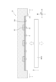
- FIG. 3 is a schematic cross-sectional view in the tire width direction showing an example of a mold and a green tire that can be used in the tire manufacturing method according to an embodiment of the present invention.
- FIG. 4 is an enlarged front sectional view showing the vicinity of the serial plate held by the upper mold in FIG. 3 together with an electronic device before being fixed to the serial plate.
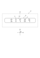
- FIG. 5 is a schematic view taken along the line XX in FIG. 4.
- reference numeral 30 denotes a tire vulcanizing device, and this tire vulcanizing device 30 vulcanizes an unvulcanized tire, that is, a green tire 20, thereby producing, for example, a tire 10 as shown in FIG. can be manufactured.
- the raw tire 20 includes a pair of bead portions 21, sidewall portions 22 extending outward in the tire radial direction from each bead portion 21, and outer ends of these sidewall portions 22 in the tire radial direction. and a tread portion 15 that connects the.
- the sidewall portion 22 and bead portion 21 of the green tire 20 may be collectively referred to as a tire side portion 28.
- the internal members of the tire that the raw tire 20 has similarly to the tire 10, such as a bead core, a carcass, and a belt, are not shown to avoid complication.
- the tire vulcanizing device 30 has a mold 31, and the mold 31 includes at least a substantially ring-shaped lower mold 32 and a substantially ring-shaped upper mold 33.
- the lower mold 32 has a tire side part molding surface 323 on the upper surface of the approximately central region in the tire radial direction, for molding at least a part of the tire side part 28 on one side (lower side) of the green tire 20.
- the upper mold 33 has a tire side molding surface 333 on the lower surface of the approximately central region in the tire radial direction, which molds at least a portion of the tire side portion 28 on the other side (upper side) of the green tire 20. are doing.
- numerals 321 and 331 are tread part molding surfaces of the mold 31 on which the tread part 23 of the raw tire 20 is molded, and numerals 322 and 332 are respectively on one side of the raw tire 20.
- This is a lug groove forming bone in the mold 31 for forming lug grooves in the (lower) half and the other (upper) half.
- the lug groove forming bones 322 and 333 protrude inward in the tire radial direction from the tire radial outer end portion of the lower mold 32 and the tire radial outer end portion of the upper mold 33, respectively. At the same time, they are arranged, for example, at equal distances apart in the tire circumferential direction.
- the tire vulcanizer 30 includes a shaping unit 34 .
- the shaping unit 34 includes a one-side support 35 on which the bead portion 21 on one side (lower side) of the green tire 20 is seated and which can mainly clean up the bead portion 21, and a support body 35 on the other side of the green tire 20. It has the other side support body 36 on which the (upper) bead part 21 is seated and on which the bead part 21 can be mainly put away.
- the one-side support body 35 and the other-side support body 36 can be removably connected by a connection mechanism (not shown).
- the reference numeral 80 indicates a bend provided in the shaping unit 34, whose one end and the other end in the tire width direction are secured to the one side support 35 and the other side support 36, respectively, in a confidential state. It is a possible bladder.
- reference numerals 324 and 334 indicate approximately rectangular shapes in plan view (see FIG. 5) for holding the serial plate 50 formed on the tire side molding surfaces 323 and 333, respectively. It is a concave part.
- the bottom walls of the recesses 324 and 325 are flat surfaces that are substantially parallel to the tangents of the tire side molding surfaces 323 and 333 at the positions of the recesses 324 and 334 in the cross-sectional view of FIGS. 3 and 4. It consists of
- these serial plates 50 each have a substantially rectangular shape that is substantially the same as the recesses 324 and 334 in plan view (see FIG. 5).
- These serial plates 50 may be made of metal plates such as stainless steel, aluminum, and aluminum alloy.
- Each of these serial plates 50 is provided with an identification mark 51 consisting of letters, numbers, symbols, figures, etc., by stamping with a press or the like, to indicate the tire's serial number, manufacturing date, manufacturer name, etc. When these identification marks 51 are imprinted on the raw tire 20 and furthermore on the manufactured tire 10 by transfer, it becomes easy to identify the type of the manufactured tire 10, etc.
- the identification marks 51 are arranged at approximately equal distances in the longitudinal direction of the serial plate 50 and in the circumferential direction of the tire, and extend from the back surface to the front surface of the serial plate 50. It sticks out towards me.
- the serial plate 50 is made of a ferromagnetic material such as steel, as shown in FIG. 4, one or more serial plates (in this example, multiple )
- a magnet (for example, a permanent magnet) 52 is preferably embedded, and the serial plate 50 is preferably attracted by the magnet 52.
- the serial plate 50 is used, for example, by being fixed to the electronic device 6 or the electronic device laminate 60 including the electronic device 6.
- the electronic device 6 or the electronic device laminate 60 before being fixed to the serial plate 50 is shown together with solid white arrows indicating the positional relationship of their fixed surfaces.
- the dotted white arrow in FIG. 4 indicates that the electronic device 6 or the electronic device stack 60 may be placed on the green tire 20 (not shown in FIG. 4).
- FIGS. 4 and 5 only show the recess 334 on the upper mold 33 side and the serial plate 50 held in the recess 334, but the recess 324 on the lower mold 32 side and the serial plate 50 held in the recess 324 are shown in FIGS.
- the serial plate 50 may also have a similar configuration.
- the arrows in the tire radial direction RD and tire width direction WD shown in FIGS. 4 and 5 do not necessarily indicate the exact tire radial direction RD and tire width direction WD, respectively.
- the electronic device 6 is attached to a serial plate 50 that is a separate member from the mold 31, and the lower mold 32 and the upper mold 33 are attached to a serial plate 50 that is a separate member from the mold 31. They are arranged via a serial plate 50 which is a member of the.
- the electronic device 6 is configured to operate the lower mold 32 and the upper mold 33 in a state where the green tire 20 is placed in the vulcanization space VS, the lower mold 32 and the upper mold 33 are closed to each other, and before vulcanization is started.
- the tire manufacturing method of the present embodiment uses, for example, a tire vulcanizing device 30, a mold 31, a lower mold 32, an upper mold 33, etc., as described using FIGS. 10 is manufactured.
- the tire manufacturing method according to the present embodiment is, for example, a tire manufacturing method for obtaining a tire 10 having an electronic device 6 attached to the tire side portion 8, as described above with reference to FIG.
- the type and/or size of the tire 10 may be arbitrary, and the tire 10 may be configured, for example, as a tire in which the nominal rim diameter of the applicable rim is 20 inches or more.
- the tire manufacturing method according to the present embodiment uses a lower mold 32 and an upper mold 33 as the mold 31 for vulcanizing the green tire 20.
- the configurations of the mold 31, the lower mold 32, and the upper mold 33 are not particularly limited as long as the lower mold 32 provided vertically below and the upper mold 33 provided vertically above the lower mold 32 are used.
- the mold 31, the lower mold 32, and the upper mold 33 for example, the mold 31, the lower mold 32, and the upper mold 33 as described above with reference to FIGS. 3 to 5 can be used.
- the tire manufacturing method according to the present embodiment includes an electronic device placement step and a vulcanization step.
- the electronic device 6 is disposed near at least one of the tire outer surfaces 20o of the tire side portions 28 on the side that contacts the mold 33.
- the above-mentioned "tire side portion 28 on the side that contacts the lower mold 32 (or upper mold 33) of the green tire 20" refers to It means the tire side portion 28 of the tire half of the raw tire 20 that comes into contact. More specifically, in this example using the tire vulcanizing apparatus 30 shown in FIG.
- the electronic device 6 is placed on the tire side molding surface 323 and the tire side molding surface 333 of the upper mold 33, but as described above, in the electronic device placement process, the electronic device 6 is placed under the lower mold 32, the upper mold 33, and the green tire 20. At least one of the vicinity of the tire outer surface 20o of the tire side portion 28 on the side that contacts the mold 32, and the vicinity of the tire outer surface 20o of the tire side portion 28 on the side that contacts the upper mold 33 of the green tire 20. In other words, it may be placed at one or more sites selected from these.
- the electronic device 6 may be placed at the above-described location as a single electronic device 6 as described above with reference to FIG. As the electronic device 6 included in the electronic device stack 60 as described above, the electronic device stack 60 may be placed at the above-described site, so that the electronic device 6 may be placed at the site.
- the tire vulcanizing apparatus 30 shown in FIG. is attached to a separate member (for example, the serial plate 50 in FIG. 6, which will be described later) from the mold 31 (and by extension, the lower mold 32 and/or the upper mold 33), and is attached to the lower mold 32 and/or the upper mold 33. It is placed in the upper die 33 via a member separate from the die 31 .
- the electronic device 6 is preferably attached to a member separate from the mold 31 on the green tire 20 side. Thereby, in the manufactured tire 10, for example, a mark etc. stamped by a member separate from the mold 31 can be used as a mark of the position where the electronic device 6 is arranged, and the mark etc. The electronic device 6 can be easily placed at the position.
- the above-mentioned “mold 31” does not include the elastic member 61 (the one side elastic member 61a and the other side elastic member 61b) included in the electronic device stack 60.
- the member separate from the mold 31 is the serial plate 50.
- the serial 5 of the normal tire 10 which is usually stamped by the serial plate 50, can be electronically printed without an additional mark that can serve as a mark of the position where the electronic device 6 is placed. It can be used as a mark indicating the device placement position, and the electronic device can be easily placed at the position of the serial 5.
- the member separate from the mold 31 is not limited to the serial plate 50; for example, a member for stamping an additional mark as a mark that allows the position of the electronic device 6 to be visually recognized on the manufactured tire 10. It may also be an additional plate other than the serial plate 50. However, from the viewpoint of efficiently visualizing the position of the electronic device 6 without the need for additional marks etc. by the additional plate, it is preferable that the member separate from the mold 31 is the serial plate 50. .
- the green tire 20 is set in a mold 31 and vulcanized. More specifically, in this example using the tire vulcanizing apparatus 30 shown in FIG. 21 are seated, the one side support 35 and the other side support 36 are connected to each other by a connection mechanism (not shown), and then when the bladder 80 is filled with internal pressure, the green tire 20 becomes approximately toroid-shaped. While being deformed, it is supported by the shaping unit 34 made up of the one side support body 35, the other side support body 36, and the bladder 80.
- the green tire 20 mounted on the shaping unit 34 in this manner is carried into the upper mold 33 in an open state by a conveying means (not shown), and then is inserted into the lug groove forming ribs 322 of the lower mold 32.
- the raw tire 20 is placed on the lower die 32 while matching the lug groove forming groove formed in the tire half on one side (lower side).
- the lower mold 32 and the upper mold 33 are closed, and the green tire 20 is set (stored) in the mold 31, that is, in the vulcanization space VS. and vulcanize the green tire 20.
- the identification mark 51 formed on the serial plate 50 is transferred and stamped onto the raw tire 20, and the identification mark 51 is complemented with the identification mark 51 in the tire 10 after vulcanization, that is, the manufactured tire 10.
- a serial 5 consisting of related depressions etc. is formed.
- the serial plate 50 is removed from the tire 10.
- the electronic device 6 attached to the raw tire 20 side of the serial plate 50 is fixed to the raw tire 20, and in the tire 10 after vulcanization, that is, the manufactured tire 10, An electronic device 6 is attached to the tire 10.
- a lower mold 32 and an upper mold 33 are used as the mold 31 for vulcanizing the green tire 20.
- the tire 10 can be manufactured by vulcanizing the green tire 20.
- the lower mold 32, the upper mold 33, and the tire outer surface 20o of the tire side portion 28 on the side that contacts the lower mold 32 of the green tire 20 in the electronic device placement step, the lower mold 32, the upper mold 33, and the tire outer surface 20o of the tire side portion 28 on the side that contacts the lower mold 32 of the green tire 20.
- the electronic device 6 is disposed near the tire outer surface 20o of the tire side portion 28 on the side that contacts the upper mold 33 of the green tire 20, and Vulcanize the tire 20.
- the electronic device 6 can be attached to the tire side portion 8 of the tire 10 by a simple method of just vulcanizing the raw tire 20, without attaching it near the tire outer surface 10o of the tire 10 after vulcanization. It can be attached near the outer surface 10o. This point is particularly useful when the tire 10 is a large tire, for example, where the nominal rim diameter of the applicable rim is 20 inches or more.
- the electronic device 6 can be attached near the tire outer surface 10o of the tire side portion 8 of the manufactured tire 10 by a simple method, and as a result, for example, communication performance of the electronic device 6 can be improved.
- the electronic device 6 is attached to a member separate from the mold 31, and a member separate from the mold 31 is attached to the lower mold 32 and/or the upper mold 33.
- the effects of the serial plate 50 being disposed through the mold 31 and the serial plate 50 being a separate member from the mold 31 are as described above.
- the electronic device 6 includes the elastic member 61 (one side elastic member 61a and/or the other side elastic member 61b) on at least a part of the surface of the electronic device 6;
- the electronic device 6 is preferably configured as an electronic device stack 60 including the electronic device 6 as shown in FIGS. 2(b) to 2(c).
- the elastic member 61 between the electronic device 6 and the lower die 32, the upper die 33, and/or the green tire 20, which further improves the durability of the electronic device 6. /Or the adhesion to the tire body can be improved.
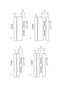
- FIGS. 6(a) to 6(d) each illustrate an electronic device arrangement step in a tire manufacturing method according to an embodiment of the present invention.
- FIG. 3 is a drawing for explaining different examples of configurations of a serial plate, an elastic member, and an electronic device as members separate from a mold, which are arranged in the mold.
- FIGS. 6(a) to 6(d) mainly show the arrangement relationship in the tire width direction of the serial plates 50, etc., and the approximate thickness relationship between the one side elastic member 61a and the other side elastic member 61b, This is a schematic diagram for comparison and explanation only, and in reality, the serial plates 50 and the like are fixed to each other, and each dimension is not accurate.
- the electronic device 6, electronic device stack 60, one side elastic member 61a, and other side elastic member 61b in FIGS. 6(a) to 6(d) are the same as those in FIGS. 2(b) to 2(c), respectively. It corresponds to Further, in FIG. 6, the electronic device 6 is depicted with the vertical direction of the paper surface as the thickness direction TD (not shown) of the electronic device 6. However, the configurations of the serial plate 50, the elastic member (one side elastic member 61a and/or the other side elastic member 61b), and the electronic device 6 as members separate from the mold 31, which are placed in the electronic device placement step, are as follows. , is not limited to the example of FIG.
- the electronic device 6 used in the electronic device placement process may include elastic members (one side elastic member 61a and the other side elastic member 61b) on both surfaces in the thickness direction (see FIG. 2(c) and (d)), an elastic member (one side elastic member 61a) may be provided only on the surface on one side in the thickness direction, especially on the surface on the serial plate 50 side (see FIG. 2(a). ), see (b)). Since the electronic device 6 is provided with an elastic member (one side elastic member 61a) on the surface on the serial plate 50 side, the durability of the electronic device 6 and the adhesion to the serial plate 50 are improved, and the surface on the green tire 20 side is improved.
- the thickness of the elastic member is different between the examples of FIGS. 6(a) and 6(b), and FIG. 6(c) and FIG. 6(d). .
- the electronic device 6 placed in the mold 31 (lower mold 32 and/or upper mold 33) (see FIG. 3) is placed in the mold 31 as, for example, the configuration illustrated in FIG.
- the serial plate 50, the elastic member (one side elastic member 61a and/or the other side elastic member 61b), and the electronic device 6 be integrated in advance before being placed in the mold 31.
- the elastic members (one side elastic member 61a and/or the other side elastic member 61b) are applied in order to ensure adhesive force between the respective members due to the elastic member. You can keep it warm.
- the distance between the center of the electronic device 6 in the thickness direction and the serial plate 50 is preferably 0.1 to 10.0 mm.
- the electronic device 6 is less susceptible to damage when the tire is running, and as a result, the durability of the electronic device 6 can be improved, and information on the electronic device 6 can be easily read from the outside. From the same point of view, it is more preferable that the interval is 0.5 to 5.0 mm.
- the electronic device 6 is placed on the lower mold 32 and/or the upper mold 33, and ultimately on the mold 31 via an adhesive. In this case, it is possible to suppress the electronic device 6 from shifting or falling from the mold 31, for example in a later vulcanization step. More specifically, in the electronic device placement process, the electronic device 6 may be directly bonded and placed on the mold 31 via an adhesive (not shown); As in the example, it may be arranged with respect to the mold 31 via an elastic member (one side elastic member 61a) and a member separate from the mold 31 (for example, the serial plate 50), in which case, The electronic device 6 may be placed on the mold 31 with an adhesive provided between at least one adjacent member among the members from the electronic device 6 to the mold 31.
- the electronic device 6 can be placed in the mold 31 via an adhesive (not shown) provided only between the one side elastic member 61a and the serial plate 50.
- an adhesive not shown
- the above adhesive may be used only on the upper mold 33 side, that is, the electronic device 6 is placed only on the upper mold 33. It may also be placed via adhesive. This is because the electronic device 6 easily falls from the upper mold 33.
- the electronic device 6 is preferably placed on both the lower mold 32 and the upper mold 33.
- the tire side portion 8 in the vicinity of the tire outer surface 10o in the tire half portion on one side and the tire side portion 8 in the tire half portion on the other side with the tire equatorial plane CL as the boundary. Since the electronic device 6 is attached to both sides near the tire outer surface 10o, the information stored in the electronic device 6 can be read from the outside on both sides in the tire width direction, and the mounting direction of the tire 10 on the vehicle can be read.
- the communication performance of the electronic device 6 can be ensured, and even if the electronic device 6 on one side breaks down and stops functioning, the electronic device on the other side can be It becomes possible to read information from 6.
- the electronic device 6 may be placed only on one of the lower mold 32 and the upper mold 33. In this case, the electronic device 6 may especially be arranged only on the lower mold 32. This is because the electronic device 6 placed on the lower mold 32 is difficult to shift due to the action of gravity.
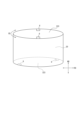
- FIG. 7 shows an example of the arrangement relationship on the mold circumference of electronic devices arranged on the lower mold side and the upper mold side in the electronic device arrangement step in the tire manufacturing method according to an embodiment of the present invention.
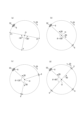
- FIGS. 8(a) to 8(d) show the lower mold side in the electronic device placement step in the tire manufacturing method according to an embodiment of the present invention. It is a drawing for explaining a different example of the arrangement relationship on the mold circumference of the serial plate and the electronic device arranged on the upper mold side.
- the electronic devices 6 are installed on the lower mold 32, the upper mold 33, and the tire side portion 28 of the green tire 20 on the side that contacts the lower mold 32 so that two or more electronic devices 6 are installed in the manufactured tire 10.
- the tire outer surface 20o hereinafter also referred to as "tire side part 28 on the lower mold 32 side of the raw tire 20”
- the tire side part 28 on the side that contacts the upper mold 33 of the raw tire 20 A total of two or more may be arranged near the outer surface 20o (hereinafter also referred to as "tire side portion 28 on the upper die 33 side of the green tire 20").
- one or more of the two or more electronic devices 6 is located on the lower mold 32 side (including the lower mold 32 and the tire side portion 28 of the green tire 20 on the lower mold 32 side. , the same.), and one or more of the electronic devices 6 are arranged on the upper mold 33 side (including the upper mold 33 and the tire side part 28 of the green tire 20 on the upper mold 33 side.
- These two or more electronic devices 6 are arranged so as to be spaced apart from each other by 45° or more in the circumferential direction of the mold when viewed in the direction of the tire rotation axis in the mold 31 and centered on the position of the tire rotation axis.
- two electronic devices 6 are arranged on the side of the upper mold 33 (indicated by the tire side molding surface 333 of the upper mold 33 in the figure), and these four electronic devices 6 are arranged in the direction of the tire rotation axis. , are arranged so as to be spaced apart from each other by 45° or more (approximately 90° in the example shown) in the mold circumferential direction.
- the two or more electronic devices 6 are arranged at equal intervals in the circumferential direction of the mold. According to such an arrangement, in the manufactured tire 10, the effects of events that cause failure or peeling during tire running are smoothed out, and any of the electronic devices 6 can remain functioning. This is because it can further ensure that Note that "arranged at equal intervals in the mold circumferential direction" means that the electronic devices 6 are arranged at equal intervals on the lower mold 32 side and the upper mold 33 side, regardless of whether the electronic devices 6 are located on the lower mold 32 side or the upper mold 33 side.
- They may be arranged at equal intervals in either one or both, or they may be arranged at equal intervals when viewed in the direction of the tire rotation axis in the mold 31 and when both the lower mold 32 side and the upper mold 33 side are viewed together. You can.
- the electronic devices 6 arranged on the lower mold 32 side and the electronic devices 6 arranged on the upper mold 33 side are arranged alternately in the mold circumferential direction. According to such an arrangement, in the manufactured tire 10, when an event that causes a failure or the like occurs in one electronic device 6, the other electronic device 6 adjacent in the tire circumferential direction This is because it is located in a different half of the tire width direction from the electronic device 6, so that it is possible to avoid as much as possible the effects of events that may cause a failure on the other electronic device 6.
- the number of electronic devices 6 arranged on the lower mold 32 side and the number of electronic devices 6 arranged on the upper mold 33 side are the same. In this case, the influence of the event that causes the failure can be further reduced.
- one or more electronic devices 6, preferably two or more electronic devices 6 may be placed on the mold circumference on at least one of the lower mold 32 side and the upper mold 33 side.
- FIG. 8 shows the serial plate 50 and the electronic device 6 on one side of the mold 31 (for example, the lower mold 32 side. The lower mold 32 side will mainly be described below, but the same applies to the upper mold 33 side).
- FIG. 8(a) shows an example in which one electronic device 6 is arranged on the circumference of the mold
- FIGS. 8(b) to 8(d) show the arrangement relationship between the electronic devices 6 and 6 shows an example in which two or more pieces are arranged on the circumference of the mold.
- the serials 5 provided on one half and the other half in the tire width direction are usually one each on the circumference of the tire.
- the number of serial plates 50 disposed on the upper die 33 side is also usually one on the circumference of the die. Therefore, in the electronic device placement process, for example, on the lower mold 32 side, the electronic device 6 attached to the serial plate 50 (hereinafter also referred to as “electronic device 6 with serial plate”) and the electronic device 6 that is not attached to the serial plate 50 are When arranging two or more electronic devices 6 (hereinafter also referred to as "independent electronic devices 6"), the electronic devices 6 (hereinafter also referred to as "independent electronic devices 6") may be arranged as shown in the examples shown in FIGS.
- the individual electronic devices 6 can be arranged at equal intervals on the circumference of the mold, starting from the electronic device 6 with the serial plate, in other words, so that the center angles ⁇ around the tire rotation axis O are equal. preferable.
- the position of the serial 5 with good visibility is used as a reference. Since the electronic devices 6 are attached at equal intervals on the circumference of the tire, it becomes easy to grasp the positions of the electronic devices 6.
- FIG. 8(b) is an example in which the two electronic devices 6 are arranged at equal intervals on the mold circumference so that the central angle ⁇ is 180°, and FIG.
- FIG. 8(c) is an example in which three electronic devices 6 are arranged at equal intervals on the mold circumference so that the central angle ⁇ is 120°
- FIG. is an example in which four electronic devices 6 are arranged at equal intervals on the circumference of the mold so that the central angle ⁇ is 90°.
- the central angle seen from an arbitrary point P on the circumference of the mold is
- the points on the mold circumference that are ⁇ 90° are Pr and Pl (see Fig. 8(a))
- a plurality of electronic devices 6 are arranged around the mold so that there are 6 electronic devices 6. In this case, even if the manufactured tire 10 is a large tire and is standing still vertically in any rotating position, the center angle range of ⁇ 90° from the lowest point of the stationary tire 10. Since the electronic device 6 is always present inside the vehicle, convenience at the site is improved.
- the electronic device 6 in the tire manufacturing method in the above-described embodiment, was mainly placed only on the lower mold 32 and/or the upper mold 33, but in addition to or in place of this, In the electronic device placement step, the electronic device 6 is placed near the tire outer surface 10o of the tire side portion 8 on the green tire 20 side, that is, on the side that contacts the lower die 32 of the green tire 20, and/or on the green tire 20. It may be arranged near the tire outer surface 10o of the tire side portion 8 on the side that contacts the mold 33.
- the serial plate 50 the elastic member (one side elastic member 61a and/or the other side elastic member 61b), and the electronic device 6 shown in each example of FIG. 6, these may be integrated in advance. Then, the electronic device 6 may be placed at the above-mentioned portion of the green tire 20 by placing it on the green tire 20. Further, in the above case, in particular, the electronic device 6 is connected to at least the serial plate 50 or the serial plate 50 and the elastic member (one side elastic member 61a and/or the other side elastic member 61b) may be placed near the tire outer surface 10o of the tire side portion 8 on the side that contacts the upper mold 33 of the green tire 20. This is because the serial plate 50 placed on the upper mold 33 may easily fall off the upper mold 33, for example, when the upper mold 33 is raised and lowered before and after vulcanization.
- the method for manufacturing a tire according to the present invention and the tire according to the present invention can be suitably used as a method for manufacturing any type of tire and as any type of tire, such as tires for passenger cars, tires for trucks and buses, tires for construction and It can be suitably used as a tire for mining vehicles, etc., or a manufacturing method thereof, and particularly, it can be suitably used as a tire for construction/mining vehicles, or a manufacturing method thereof.
Landscapes
- Engineering & Computer Science (AREA)
- Mechanical Engineering (AREA)
- Physics & Mathematics (AREA)
- Health & Medical Sciences (AREA)
- Oral & Maxillofacial Surgery (AREA)
- Thermal Sciences (AREA)
- Moulds For Moulding Plastics Or The Like (AREA)
- Heating, Cooling, Or Curing Plastics Or The Like In General (AREA)
- Tyre Moulding (AREA)
- Tires In General (AREA)
Abstract
Description
本願は、2022年7月25日に日本に出願された特願2022-118281号に基づく優先権を主張するものであり、その内容の全文をここに援用する。
タイヤサイド部に電子装置を取り付けたタイヤを得るための、タイヤの製造方法であって、
生タイヤを加硫するための金型として、下型及び上型を用い、
前記下型、前記上型、前記生タイヤの前記下型に接触する側のタイヤサイド部のタイヤ外表面近傍、及び前記生タイヤの前記上型に接触する側のタイヤサイド部のタイヤ外表面近傍、のうちの少なくともいずれか1つに、前記電子装置を配置する、電子装置配置工程と、
前記電子装置配置工程の後に、前記金型内に前記生タイヤをセットして加硫する、加硫工程と、
を含むことを特徴とする。
上記のタイヤの製造方法によって、製造されたことを特徴とする。
本発明に係る、タイヤによれば、タイヤの製造の際に、簡易な方法でタイヤサイド部のタイヤ外表面近くに電子装置を取り付けることができる。
各図において共通する部材・部位には同一の符号を付している。
本明細書において、「タイヤ周方向」とは、タイヤの回転軸を中心にタイヤが回転する方向をいい、「タイヤ径方向」とは、タイヤの回転軸と直交する方向をいい、「タイヤ幅方向」とは、タイヤの回転軸と平行な方向をいう。一部の図面では、タイヤ周方向を符号「CD」で示し、タイヤ径方向を符号「RD」で示し、タイヤ幅方向を符号「WD」で示している。
また、本明細書において、タイヤ径方向に沿ってタイヤの回転軸に近い側を「タイヤ径方向内側」と称し、タイヤ径方向に沿ってタイヤの回転軸から遠い側を「タイヤ径方向外側」と称する。さらに、本明細書において、タイヤ幅方向に沿ってタイヤ赤道面CLに近い側を「タイヤ幅方向内側」と称し、タイヤ幅方向に沿ってタイヤ赤道面CLから遠い側を「タイヤ幅方向外側」と称する。また、本明細書において、「タイヤ内表面」とは、タイヤ内腔に面するタイヤの表面を指し、「タイヤ外表面」とは、タイヤの外部に面するタイヤの表面を指す。
本明細書において、上記の「タイヤ周方向」等の用語及び「CD」等の符号は、加硫後のタイヤ(即ち、完成品のタイヤ)のみならず、加硫前の生タイヤにおいても、使用されるものとする。また、本明細書において、生タイヤを加硫するための金型について、上記と同様の意味で、「金型周方向」等の用語及び「CD」等の符号を使用する場合がある。
まず、図1を参照しつつ、本発明の任意の実施形態に係るタイヤの製造方法によって得ることのできるタイヤの一例、ひいては、当該タイヤの製造方法によって得られたタイヤの一例、換言すれば、本発明の一実施形態に係るタイヤについて、説明する。
図1は、本発明の一実施形態に係るタイヤ10を説明するための図面であり、当該タイヤ10の、タイヤ幅方向概略断面図である。
本発明の一実施形態に係るタイヤ10は、後述する、本発明の任意の実施形態に係るタイヤの製造方法によって、製造されたタイヤであるので、後述する、当該タイヤの製造方法によって得られる効果を享受することができ、換言すれば、当該タイヤ10によれば、タイヤ10の製造の際に、簡易な方法でタイヤサイド部のタイヤ外表面近くに電子装置を取り付けることができる。
なお、本発明の実施形態のタイヤ10は、任意の種類及び/又は任意のサイズのタイヤとして構成されてよい。例えば、本実施形態のタイヤ10、ひいては、後述する本発明の一実施形態に係るタイヤの製造方法により製造されるタイヤ10は、適用リムのリム径の呼びが、20インチ以上であるタイヤとして、構成されてよい。適用リムのリム径の呼びが20インチ以上である、当該リム径の呼びの例としては、例えば、25インチ、29インチ、33インチ、35インチ、49インチ、51インチ、57インチ、63インチ等が挙げられる。タイヤ10の適用リムのリム径の呼びが20インチ以上である場合、本実施形態によれば、電子装置がタイヤ内表面側に取り付けられると例えば通信性に課題を生じやすい、そのようなサイズが大きいタイヤの、タイヤサイド部のタイヤ外表面近くに容易に電子装置を取り付けることができる。
ビード部1は、タイヤ10をリムに装着したときに、タイヤ径方向内側及びタイヤ幅方向外側においてリムに接するように構成された部分である。トレッド部3は、タイヤ10のうち、1対のトレッド端どうしの間のタイヤ幅方向部分である。サイドウォール部2は、1対のビード部1とトレッド部3との間の部分である。本明細書において、タイヤ10のサイドウォール部2とビード部1とを総称して、タイヤサイド部8と呼ぶ場合がある。なお、上記サイドウォール部2とは、少なくとも後述するベルト7よりタイヤ径方向内側の部分であって、ビード部1よりタイヤ径方向外側の部分を指す。
ここで、本明細書において、「電子装置」とは、電子部品を備える装置であって、例えば、外部との通信機能を有するものを指す。
なお、本明細書において、タイヤ10のうち、電子装置6又は後述する電子装置積層体60を除く部分を、「タイヤ本体」と称し、後述する生タイヤ20のうち、電子装置6又は後述する電子装置積層体60を除く部分を、「生タイヤ本体」と称する場合がある。
カーカス4を構成する各カーカスプライは、1本又は複数本のカーカスコードと、カーカスコードを被覆する被覆ゴムと、を含んでいる。カーカスコードは、例えば、モノフィラメント又は撚り線で形成することができる。本例において、カーカスコードは、スチール製である。カーカスコードがスチール製であることにより、例えばサイズが大きいタイヤでカーカスを簡易なラジアル構造としても、十分な強度が得られる。
また、本例において、カーカス4は、ラジアル構造である。即ち、カーカス4のカーカスプライが含む各カーカスコードは、実質的にタイヤ幅方向に沿って(即ち、トレッド部3のタイヤ径方向外方からの投影視において、タイヤ幅方向に対して実質的に0°の角度で傾斜せずに)、延びている。
但し、カーカスコードは、ポリエステル、ナイロン、レーヨン、アラミドなどからなる有機繊維から構成されていてもよい。また、カーカス4は、バイアス構造であってもよい。
電子装置6は、タイヤサイド部8内に埋め込まれていてもよいし、タイヤサイド部8のタイヤ外表面10o上に取り付けられていてもよい。図1の例では、電子装置6は、サイドウォール部2内に埋め込まれている。
また、本実施形態において、電子装置6は、それ単体(図2(a)参照)でタイヤ10のタイヤサイド部8に取り付けられていてもよいし、電子装置6の表面の少なくとも一部に弾性部材61を備えている、電子装置6を含む電子装置積層体60(図2(b)~図2(c)参照)としてタイヤ10のタイヤサイド部8に取り付けられていてもよい。換言すれば、電子装置6は、後述する本発明の一実施形態に係るタイヤの製造方法における電子装置配置工程において、それ単体(図2(a)参照)で用いられてもよいし、上記電子装置積層体60(図2(b)~図2(c)参照)として用いられてもよい。電子装置配置工程において、電子装置6が、当該電子装置6の表面の少なくとも一部に弾性部材61を備えている場合、電子装置6の耐久性及び/又はタイヤ本体への固着性を向上させることができる。
なお、電子装置6が例えば後述する図2(a)~図2(c)のいずれかに示すようなRFタグである場合、薄板状のICチップ6aにおける厚さ方向TD両側の面(例えば図2(a)では、紙面表側と裏側の面)がタイヤ外表面10oに沿うように(即ち、両者が略平行になるように)、上記タイヤ外表面10o側に取り付けられ、当該ICチップ6aの厚さ方向TDの中心が上記深さ位置に配置されていてよい。
さらに、図示の例で、タイヤサイド部8におけるカーカス4のタイヤ幅方向外側には、タイヤサイド部8のタイヤ外表面10oを形成するサイドゴムが備えられている。
また、本実施形態のタイヤ10は、タイヤ内表面が、空気及び/又はガス低透過性のインナーライナー(特に図示せず)で構成されている。
本例において、アンテナ6bは、ICチップ6aに接続され、直線状、波状、又は螺旋状(図示の例では、螺旋状)に延びている。本例では、2本のアンテナ6bが、ICチップ6aから互いに反対方向に延びている。但し、アンテナ6bは、ICチップ6aから一方側だけに延びていてもよい。また、本例では、2本のアンテナ6bは、後述するICチップ6aの長辺方向LDの長さが同じである。但し、2本のアンテナは、ICチップ6aの長辺方向LDの長さが互いに異なっていてもよい。
本例において、ICチップ6aは、平面視(図2(a)参照)略矩形状の厚さの薄い薄板状を呈している。ここで、ICチップ6aの「厚さ」とは、平面視でICチップ6aの長辺に沿う方向に平行な方向(以下、「ICチップ(6a)の長辺方向」ともいう。)LDと、平面視でICチップ6aの短辺に沿う方向に平行な方向(以下、「ICチップ(6a)の短辺方向」ともいう。)SDと、の双方に垂直な方向(以下、「ICチップ(6a)の厚さ方向」ともいう。)TDの厚さを指す。なお、本例において、ICチップ(6a)の長辺方向LDは、電子装置(6)の長手方向でもあり、ICチップ(6a)の短辺方向SDは、電子装置(6)の短手方向でもあり、ICチップ(6a)の厚さ方向TDは、電子装置(6)の厚さ方向でもある。
ICチップ6aは、例えば、任意の既知のメモリである記憶部及び任意の既知のプロセッサである制御部を有している。ICチップ6aは、1つ以上のアンテナ6bで受信する電磁波により発生する誘導起電力により動作してもよい。即ち、電子装置6は、パッシブ型の通信装置であってもよい。或いは、電子装置6は、電池をさらに備え、自らの電力により電磁波を発生して通信可能であってもよい。即ち、電子装置6は、アクティブ型の通信装置であってもよい。ICチップ6aの制御部は、例えば、記憶部に記憶されたタイヤの製造管理、出荷管理、使用履歴管理等のデータを読み取る、或いは、記憶部にこれらのデータを書き込むことができる。
なお、図2(b)の例における電子装置6自体の構成は、電子装置6単体として説明した上述の図2(a)の電子装置6の構成と同じである。
なお、図2(c)の例における電子装置6自体の構成も、電子装置6単体として説明した上述の図2(a)の電子装置6の構成と同じである。
なお、図1では電子装置6を含む電子装置積層体60を簡略化して記載しているが、図1の例において、電子装置6は、薄板状のICチップ6aの厚さ方向TDにおける一方側及び他方側の表面がタイヤ外表面10oに沿うように(即ち、両者が略平行になるように)、タイヤ外表面10oの近傍に取り付けられている。
次に、本発明の一実施形態に係るタイヤの製造方法について、図3~図5を参照しつつ説明する。
図3は、本発明の一実施形態に係るタイヤの製造方法を説明するための、当該タイヤの製造方法に用いられ得る金型及び生タイヤの一例を示す、タイヤ幅方向概略断面図である。図4は、図3の上型に保持されたセリアルプレート近傍を、当該セリアルプレートに固着される前の電子装置とともに示す、拡大正面断面図である。図5は、図4のX-X概略矢視図である。
図3において、符号30はタイヤ加硫装置であり、このタイヤ加硫装置30は、未加硫のタイヤ、即ち、生タイヤ20を加硫することで、例えば図1に示すようなタイヤ10を製造することができる。生タイヤ20は、タイヤ10と同様に、一対のビード部21と、各ビード部21からそれぞれタイヤ径方向外側に向かって延びるサイドウォール部22と、これらサイドウォール部22のタイヤ径方向外端同士を連結するトレッド部15と、を備えている。本明細書において、生タイヤ20のサイドウォール部22とビード部21とを総称して、タイヤサイド部28と呼ぶ場合がある。ここで、図3においては、生タイヤ20がタイヤ10と同様に有するタイヤの内部部材、例えば、ビードコア、カーカス、ベルト等は、煩雑を避けるため、その記載が省略されている。
図3中、符号321及び符号331は、生タイヤ20のトレッド部23に対し型付けを行う、金型31におけるトレッド部型付け面であり、符号322及び符号332は、それぞれ、生タイヤ20の一方側(下側)の半部及び他方側(上側)の半部にラグ溝を形成するための、金型31におけるラグ溝形成用骨である。図3に示すように、ラグ溝形成用骨322及び333は、それぞれ、下型32のタイヤ径方向外側端部分及び上型33のタイヤ径方向外側端部分から、タイヤ径方向内側に向かって突出するとともに、タイヤ周方向に例えば等距離離れて配置されている。
本例において、タイヤ加硫装置30は、シェーピングユニット34を有している。当該シェーピングユニット34は、生タイヤ20の一方側(下側)のビード部21が着座されて当該ビード部21を主に片付けすることができる、一方側支持体35と、生タイヤ20の他方側(上側)のビード部21が着座されて当該ビード部21を主に片付けすることができる、他方側支持体36と、を有している。これら一方側支持体35及び他方側支持体36は、図示していない連結機構により、脱着可能に連結されることができる。
なお、図3中、符号80は、上記一方側支持体35及び他方側支持体36に、タイヤ幅方向の一端及び他端がそれぞれ機密状態で係止された、シェーピングユニット34に設けられた屈曲可能なブラダである。
セリアルプレート50が、スチール等の強磁性体から構成されている場合には、図4に示すように、上型33の凹部334の底壁又はその近傍に1つ又は複数(本例では、複数)の磁石(例えば、永久磁石)52を埋設し、当該磁石52によりセリアルプレート50を吸着することが好ましい。これにより、例えば、加硫前後の上型33の昇降等によりセリアルプレート50が上型33から落下等することを、簡単な構造で効果的に抑制することができる。
なお、後述する本発明の一実施形態に係るタイヤの製造方法における電子装置配置工程において、セリアルプレート50は、電子装置6又は電子装置6を含む電子装置積層体60と例えば固着されて用いられることになるが、図4においては、セリアルプレート50に固着される前の、当該電子装置6又は電子装置積層体60が、互いの固着面の位置関係を示す実線の白太矢印とともに示されている。図4における点線の白太矢印は、当該電子装置6又は電子装置積層体60が、生タイヤ20(図4では、図示せず)に配置される場合があることを示している。
但し、電子装置6は、生タイヤ20が加硫空間VSに載置され、下型32及び上型33が互いに閉止され、加硫が開始される前の状態で、下型32、上型33、生タイヤ20の下型32に接触する側のタイヤサイド部28のタイヤ外表面20o近傍、及び生タイヤ20の上型33に接触する側のタイヤサイド部28のタイヤ外表面20o近傍、のうちの少なくともいずれか1つに、配置されていればよい。
本実施形態のタイヤの製造方法は、例えば、図3~図5を用いて説明したような、タイヤ加硫装置30,ひいては、金型31、下型32及び上型33等を用いて、タイヤ10を製造するものである。
本実施形態に係るタイヤの製造方法は、例えば、図1を参照しつつ前述したような、タイヤサイド部8に電子装置6を取り付けたタイヤ10を得るための、タイヤの製造方法である。前述のとおり、タイヤ10の種類及び/又はサイズは任意であってよいが、タイヤ10は、例えば、適用リムのリム径の呼びが、20インチ以上であるタイヤとして、構成されてよい。
図3を参照して、電子装置配置工程では、下型32、上型33、生タイヤ20の下型32に接触する側のタイヤサイド部28のタイヤ外表面20o近傍、及び生タイヤ20の上型33に接触する側のタイヤサイド部28のタイヤ外表面20o近傍、のうちの少なくともいずれか1つに、電子装置6を配置する。ここで、上記「生タイヤ20の下型32(又は、上型33)に接触する側のタイヤサイド部28」とは、後述する加硫工程において、下型32(又は、上型33)に接触する生タイヤ20のタイヤ半部における、タイヤサイド部28、との意味である。
より具体的に、図3に示すタイヤ加硫装置30を用いる本例では、電子装置配置工程において、電子装置6は、下型32及び上型33(具体的には、下型32のタイヤサイド部型付け面323及び上型33のタイヤサイド部型付け面333)に配置されるが、上述のとおり、電子装置配置工程において、電子装置6は、下型32、上型33、生タイヤ20の下型32に接触する側のタイヤサイド部28のタイヤ外表面20o近傍、及び生タイヤ20の上型33に接触する側のタイヤサイド部28のタイヤ外表面20o近傍、のうちの少なくともいずれか1つに、換言すれば、これらから選択される1つ以上の部位に、配置されればよい。
電子装置6は、図2(a)を参照しつつ前述したような電子装置6単体として、上述の部位に配置されてもよいし、図2(b)~図2(c)を参照しつつ前述したような電子装置積層体60に含まれる電子装置6として、当該電子装置積層体60が上述の部位に配置されることにより電子装置6が当該部位に配置されてもよい。
図3を参照して、加硫工程では、上述の電子装置配置工程の後に、金型31内に生タイヤ20をセットして加硫する。
より具体的に、図3に示すタイヤ加硫装置30を用いる本例では、加硫工程において、例えば、一方側支持体35及び他方側支持体36に未加硫の生タイヤ20の両ビード部21がそれぞれ着座された後、これら一方側支持体35及び他方側支持体36どうしが図示しない連結機構により連結され、その後、ブラダ80内に内圧が充填されると、生タイヤ20は略トロイド状に変形しながら、これら一方側支持体35、他方側支持体36及びブラダ80からなるシェーピングユニット34に支持される。次に、このようにしてシェーピングユニット34に装着された生タイヤ20は、図示しない搬送手段により開放状態の下、上型33内に搬入された後、下型32のラグ溝形成用骨322と生タイヤ20の一方側(下側)のタイヤ半部に形成されたラグ溝形成用溝とを合致させながら下型32上に載置される。その後、下型32及び上型33を閉止して、金型31内、即ち、加硫空間VS内に生タイヤ20をセット(収納)した後、ブラダ80内に高温・高圧の加硫媒体を供給して、生タイヤ20を加硫する。
なお、加硫工程において、セリアルプレート50に形成された識別標識51が生タイヤ20に転写・刻印され、加硫後のタイヤ10、即ち、製造されたタイヤ10において、当該識別標識と51と補完関係にある凹み等からなるセリアル5が形成される。加硫後のタイヤ10においては、セリアルプレート50は、タイヤ10から取り外される。
また、本例において、加硫工程において、セリアルプレート50の生タイヤ20側に取り付けられた電子装置6が生タイヤ20に固着され、加硫後のタイヤ10、即ち、製造されたタイヤ10において、電子装置6がタイヤ10に取り付けられる。
まず、本実施形態に係るタイヤの製造方法によれば、生タイヤ20を加硫するための金型31として、下型32及び上型33を用いる。これにより、製造するタイヤ10が、例えば、適用リムのリム径の呼びが20インチ以上である、サイズが大きいタイヤである場合であっても、支障なく容易に当該タイヤ10に対応するサイズが大きい生タイヤ20を加硫し、当該タイヤ10を製造することができる。
また、本実施形態に係るタイヤの製造方法によれば、電子装置配置工程において、下型32、上型33、生タイヤ20の下型32に接触する側のタイヤサイド部28のタイヤ外表面20o近傍、及び生タイヤ20の上型33に接触する側のタイヤサイド部28のタイヤ外表面20o近傍、のうちの少なくともいずれか1つに、電子装置6を配置し、加硫工程において、当該生タイヤ20を加硫する。これにより、電子装置6は、生タイヤ20を加硫するだけの簡易な方法で、加硫後にタイヤ10のタイヤ外表面10o近くに貼り付けたりすることなく、タイヤ10のタイヤサイド部8のタイヤ外表面10o近くに取り付けることができる。この点は、タイヤ10が、例えば、適用リムのリム径の呼びが20インチ以上であるような、サイズが大きいタイヤである場合に、特に有用である。
以上より、本実施形態に係るタイヤの製造方法によれば、簡易な方法で、製造されたタイヤ10の、タイヤサイド部8のタイヤ外表面10o近くに電子装置6を取り付けることができ、ひいては、電子装置6の例えば通信性を向上することができる。
但し、電子装置配置工程において配置される、金型31とは別体の部材としてのセリアルプレート50、弾性部材(一方側弾性部材61a及び/又は他方側弾性部材61b)及び電子装置6の構成は、図6の例に限定されるものではない。
また、図6(a)と図6(b)、及び、図6(c)と図6(d)、の例の間では、弾性部材(一方側弾性部材61a)の厚さが異なっている。当該弾性部材の厚さが厚い方が、より電子装置6の耐久性が向上する。
また、上記の場合において、上記各部材を一体化させる際、弾性部材による各部材間の接着力を確保するため、当該弾性部材(一方側弾性部材61a及び/又は他方側弾性部材61b)を加温しておいてもよい。
より具体的に、電子装置配置工程において、電子装置6は、金型31に接着剤を介して直接接着され配置されてもよいが(図示せず)、電子装置6は、例えば図6の各例のように、金型31に対して弾性部材(一方側弾性部材61a)及び金型31とは別体の部材(例えば、セリアルプレート50)等を介して配置されてもよく、その場合、電子装置6は、電子装置6から金型31までの各部材のうちの、少なくとも1つの隣接する部材間に設けた接着剤を介して金型31に配置されてもよい。例えば、図6に示す各例において、一方側弾性部材61aとセリアルプレート50との間のみに設けた接着剤(図示せず)を介して、電子装置6を金型31に配置することができる。
なお、電子装置6を、下型32及び上型33の双方に配置する場合、上型33側のみで上記接着剤が使用されてもよく、即ち、電子装置6は、上型33にのみ、接着剤を介して配置されてもよい。電子装置6は、上型33から落下しやすいからである。
但し、電子装置配置工程において、電子装置6は、下型32及び上型33の一方のみに配置されてもよい。この場合、電子装置6は、特に下型32のみに配置されてよい。下型32に配置された電子装置6は、重力の作用により、ずれにくいからである。
この場合、当該2個以上の電子装置6のうち、1つ以上の当該電子装置6が下型32側(下型32及び生タイヤ20の下型32側のタイヤサイド部28を、含む。以下、同じ。)に配置され、1つ以上の当該電子装置6が上型33側(上型33及び生タイヤ20の上型33側のタイヤサイド部28を、含む。以下、同じ。)に配置され、これら2個以上の電子装置6は、金型31におけるタイヤ回転軸方向視において、タイヤ回転軸の位置を中心とした際に、金型周方向で45°以上互いに離間するように配置されていると好適である。この場合、製造されたタイヤ10において、2個以上の電子装置6のうちのいずれか少なくとも1つの電子装置6に故障や剥離が生じたとしても、他のいずれかの電子装置6が機能を発揮したまま残存する可能性が高まり、ひいては、例えば、電子装置6によりタイヤ10の情報を読み書きすることができなくなることを防止することができる。
図7に示す例では、総計4個の電子装置6のうち、2個の電子装置6が下型32(図では、下型32のタイヤサイド部型付け面323で示している)側に配置され、2個の電子装置6が上型33(図では、上型33のタイヤサイド部型付け面333で示している)側に配置され、これら4個の電子装置6は、タイヤ回転軸方向視において、金型周方向で45°以上(図の例では、略90°)互いに離間するように配置されている。
図8は、金型31の一方側(例えば、下型32側。以下、下型32側について主に説明するが、上型33側も同様である。)における、セリアルプレート50及び電子装置6の配置関係を示しているものであり、図8(a)は、電子装置6が金型周上1個配置される例を示し、図8(b)~図8(d)は、電子装置6が金型周上2個以上配置される例を示している。
図8(b)は、上記のようにして、2個の電子装置6を中心角θが180°になるように金型周上に等間隔で配置した例であり、図8(c)は、上記のようにして、3個の電子装置6を中心角θが120°になるように金型周上に等間隔で配置した例であり、図8(d)は、上記のようにして、4個の電子装置6を中心角θが90°になるように金型周上に等間隔で配置した例である。
例えば、上述の実施形態におけるタイヤの製造方法では、電子装置配置工程において、主に下型32及び/又は上型33のみに電子装置6を配置したが、これに加えて又はこれに代えて、電子装置配置工程において、電子装置6を、生タイヤ20側、即ち、生タイヤ20の下型32に接触する側のタイヤサイド部8のタイヤ外表面10o近傍、及び/又は、生タイヤ20の上型33に接触する側のタイヤサイド部8のタイヤ外表面10o近傍、に配置してもよい。この場合であっても、例えば図6の各例に示す、セリアルプレート50、弾性部材(一方側弾性部材61a及び/又は他方側弾性部材61b)及び電子装置6を用い、これらを予め一体化させた上で、生タイヤ20に配置することにより、電子装置6を、生タイヤ20の上記部位に配置してよい。また、上記の場合、特には、電子装置6を、図6の各例に示すように、少なくともセリアルプレート50、又は、セリアルプレート50及び弾性部材(一方側弾性部材61a及び/又は他方側弾性部材61b)とともに、生タイヤ20の上型33に接触する側のタイヤサイド部8のタイヤ外表面10o近傍に、配置してよい。上型33に配置されたセリアルプレート50は、それ自体が、例えば加硫前後における上型33の昇降中等に上型33から落下しやすい場合があるからである。
1、21:ビード部、 11:ビードコア、 2、22:サイドウォール部、
3、23:トレッド部、 4:カーカス、
5:セリアル、 50:セリアルプレート、 51:識別標識、 52:磁石、
6:電子装置、 6a:ICチップ、 6b:アンテナ、 60:電子装置積層体、
61:弾性部材、 61a:一方側弾性部材、 61b:他方側弾性部材、
7:ベルト、 8、28:タイヤサイド部、
30:タイヤ加硫装置、 31:金型、 32:下型、 33:上型、
321、331:トレッド部型付け面、 322、332:ラグ溝形成用骨、
323、333:タイヤサイド部型付け面、 324、334:凹部、
34:シェーピングユニット、 35:一方側支持体、 36:他方側支持体、
80:ブラダ、
CD:タイヤ周方向、 CL:タイヤ赤道面、 LD:長辺方向(長手方向)、
O:タイヤ回転軸、 P、Pl、Pr:点、 RD:タイヤ径方向、
SD:短辺方向(短手方向)、 TD:厚さ方向、 VS:加硫空間、
WD:タイヤ幅方向
Claims (9)
- タイヤサイド部に電子装置を取り付けたタイヤを得るための、タイヤの製造方法であって、
生タイヤを加硫するための金型として、下型及び上型を用い、
前記下型、前記上型、前記生タイヤの前記下型に接触する側のタイヤサイド部のタイヤ外表面近傍、及び前記生タイヤの前記上型に接触する側のタイヤサイド部のタイヤ外表面近傍、のうちの少なくともいずれか1つに、前記電子装置を配置する、電子装置配置工程と、
前記電子装置配置工程の後に、前記金型内に前記生タイヤをセットして加硫する、加硫工程と、
を含むことを特徴とする、タイヤの製造方法。 - 前記電子装置配置工程において、前記電子装置は、前記金型とは別体の部材に取り付けられ、前記下型及び/又は前記上型に当該金型とは別体の部材を介して配置される、請求項1に記載のタイヤの製造方法。
- 前記金型とは別体の部材は、セリアルプレートである、請求項2に記載のタイヤの製造方法。
- 前記電子装置配置工程において、前記電子装置は、当該電子装置の表面の少なくとも一部に弾性部材を備えている、請求項1~3のいずれか1項に記載のタイヤの製造方法。
- 前記電子装置配置工程において、前記電子装置は、前記下型及び/又は前記上型に、接着剤を介して配置される、請求項1~3のいずれか1項に記載のタイヤの製造方法。
- 前記タイヤは、適用リムのリム径の呼びが、20インチ以上である、請求項1~3のいずれか1項に記載のタイヤの製造方法。
- 前記電子装置配置工程において、前記電子装置は、前記下型及び前記上型の双方に配置される、請求項1~3のいずれか1項に記載のタイヤの製造方法。
- 請求項1~3のいずれか1項に記載のタイヤの製造方法によって、製造されたことを特徴とする、タイヤ。
- 前記電子装置は、前記タイヤサイド部のタイヤ外表面からの深さが、0.1~10.0mmである位置に、配置されている、請求項8に記載のタイヤ。
Priority Applications (2)
| Application Number | Priority Date | Filing Date | Title |
|---|---|---|---|
| US18/872,933 US20260014765A1 (en) | 2022-07-25 | 2023-05-26 | Method for producing tire and tire |
| AU2023315283A AU2023315283A1 (en) | 2022-07-25 | 2023-05-26 | Method for producing tire and tire |
Applications Claiming Priority (2)
| Application Number | Priority Date | Filing Date | Title |
|---|---|---|---|
| JP2022-118281 | 2022-07-25 | ||
| JP2022118281A JP2024015903A (ja) | 2022-07-25 | 2022-07-25 | タイヤの製造方法及びタイヤ |
Publications (1)
| Publication Number | Publication Date |
|---|---|
| WO2024024255A1 true WO2024024255A1 (ja) | 2024-02-01 |
Family
ID=89706063
Family Applications (1)
| Application Number | Title | Priority Date | Filing Date |
|---|---|---|---|
| PCT/JP2023/019789 Ceased WO2024024255A1 (ja) | 2022-07-25 | 2023-05-26 | タイヤの製造方法及びタイヤ |
Country Status (4)
| Country | Link |
|---|---|
| US (1) | US20260014765A1 (ja) |
| JP (1) | JP2024015903A (ja) |
| AU (1) | AU2023315283A1 (ja) |
| WO (1) | WO2024024255A1 (ja) |
Families Citing this family (1)
| Publication number | Priority date | Publication date | Assignee | Title |
|---|---|---|---|---|
| JP2026109792A (ja) * | 2024-12-20 | 2026-07-02 | 株式会社ブリヂストン | タイヤの製造方法およびタイヤ |
Citations (8)
| Publication number | Priority date | Publication date | Assignee | Title |
|---|---|---|---|---|
| JPH02123404U (ja) * | 1989-03-24 | 1990-10-11 | ||
| JP2002137609A (ja) * | 2000-10-30 | 2002-05-14 | Yokohama Rubber Co Ltd:The | トランスポンダを配置した空気入りタイヤ及びその製造方法 |
| JP2002205516A (ja) * | 2001-01-09 | 2002-07-23 | Yokohama Rubber Co Ltd:The | トランスポンダを把持した空気入りタイヤ及びその製造方法 |
| JP2004090775A (ja) * | 2002-08-30 | 2004-03-25 | Yokohama Rubber Co Ltd:The | フィルム状電子装置を装着した空気入りタイヤ及びそのフィルム状電子装置の装着方法 |
| JP2005096423A (ja) * | 2003-08-29 | 2005-04-14 | Omron Corp | 無線icタグ接合方法、無線icタグ付き物品、及び車両 |
| JP2005216077A (ja) * | 2004-01-30 | 2005-08-11 | Bridgestone Corp | Rfid組込バーコードラベル、及び、タイヤとその管理方法 |
| JP2016533968A (ja) * | 2013-09-17 | 2016-11-04 | ブリヂストン アメリカズ タイヤ オペレーションズ、 エルエルシー | 外部に取り付けられた装置のためのタイヤ構造 |
| JP2021008266A (ja) * | 2019-06-28 | 2021-01-28 | ハンコック タイヤ アンド テクノロジー カンパニー リミテッドHankook Tire & Technology Co., Ltd. | 電子装置が一体化されたタイヤ及びその製造方法 |
Family Cites Families (2)
| Publication number | Priority date | Publication date | Assignee | Title |
|---|---|---|---|---|
| JP2013107460A (ja) * | 2011-11-18 | 2013-06-06 | Sumitomo Rubber Ind Ltd | 空気入りタイヤ |
| FR3029832B1 (fr) * | 2014-12-15 | 2017-10-20 | Michelin & Cie | Procede de pose de support pour module electronique de pneumatique |
-
2022
- 2022-07-25 JP JP2022118281A patent/JP2024015903A/ja active Pending
-
2023
- 2023-05-26 AU AU2023315283A patent/AU2023315283A1/en active Pending
- 2023-05-26 US US18/872,933 patent/US20260014765A1/en active Pending
- 2023-05-26 WO PCT/JP2023/019789 patent/WO2024024255A1/ja not_active Ceased
Patent Citations (8)
| Publication number | Priority date | Publication date | Assignee | Title |
|---|---|---|---|---|
| JPH02123404U (ja) * | 1989-03-24 | 1990-10-11 | ||
| JP2002137609A (ja) * | 2000-10-30 | 2002-05-14 | Yokohama Rubber Co Ltd:The | トランスポンダを配置した空気入りタイヤ及びその製造方法 |
| JP2002205516A (ja) * | 2001-01-09 | 2002-07-23 | Yokohama Rubber Co Ltd:The | トランスポンダを把持した空気入りタイヤ及びその製造方法 |
| JP2004090775A (ja) * | 2002-08-30 | 2004-03-25 | Yokohama Rubber Co Ltd:The | フィルム状電子装置を装着した空気入りタイヤ及びそのフィルム状電子装置の装着方法 |
| JP2005096423A (ja) * | 2003-08-29 | 2005-04-14 | Omron Corp | 無線icタグ接合方法、無線icタグ付き物品、及び車両 |
| JP2005216077A (ja) * | 2004-01-30 | 2005-08-11 | Bridgestone Corp | Rfid組込バーコードラベル、及び、タイヤとその管理方法 |
| JP2016533968A (ja) * | 2013-09-17 | 2016-11-04 | ブリヂストン アメリカズ タイヤ オペレーションズ、 エルエルシー | 外部に取り付けられた装置のためのタイヤ構造 |
| JP2021008266A (ja) * | 2019-06-28 | 2021-01-28 | ハンコック タイヤ アンド テクノロジー カンパニー リミテッドHankook Tire & Technology Co., Ltd. | 電子装置が一体化されたタイヤ及びその製造方法 |
Also Published As
| Publication number | Publication date |
|---|---|
| US20260014765A1 (en) | 2026-01-15 |
| AU2023315283A1 (en) | 2025-01-02 |
| JP2024015903A (ja) | 2024-02-06 |
Similar Documents
| Publication | Publication Date | Title |
|---|---|---|
| JP4487125B2 (ja) | 空気入りタイヤ | |
| CN110978903B (zh) | 轮胎及轮胎的制造方法 | |
| JP3860921B2 (ja) | タイヤ用トランスポンダの補助部品 | |
| JP2024015903A (ja) | タイヤの製造方法及びタイヤ | |
| JP4331528B2 (ja) | 空気入りラジアルタイヤの製造方法およびその製造方法を用いて製造された空気入りラジアルタイヤ | |
| JP7712194B2 (ja) | タイヤ | |
| EP4422854B1 (en) | Method of producing a tyre equipped with an electronic device | |
| JP7656505B2 (ja) | タイヤ | |
| JP7770263B2 (ja) | タイヤ | |
| US12420597B2 (en) | Tire, retreaded tire, and retreaded tire production method | |
| JP7712195B2 (ja) | タイヤ | |
| JP7770264B2 (ja) | タイヤ | |
| JP2024073323A (ja) | タイヤ | |
| US12570061B2 (en) | Production method for retreaded tire and retreaded tire | |
| US12397591B2 (en) | Tire | |
| EP4714682A1 (en) | Tire | |
| EP4617082A1 (en) | Heavy duty tire | |
| JP2025093159A (ja) | タイヤ | |
| US20240246363A1 (en) | Tire | |
| JP2025093160A (ja) | タイヤ | |
| JP2024087428A (ja) | タイヤの製造方法 | |
| WO2025126743A1 (ja) | タイヤ | |
| JP2025059880A (ja) | 空気入りタイヤ及びその製造方法 |
Legal Events
| Date | Code | Title | Description |
|---|---|---|---|
| 121 | Ep: the epo has been informed by wipo that ep was designated in this application |
Ref document number: 23845993 Country of ref document: EP Kind code of ref document: A1 |
|
| WWE | Wipo information: entry into national phase |
Ref document number: 18872933 Country of ref document: US |
|
| WWE | Wipo information: entry into national phase |
Ref document number: AU2023315283 Country of ref document: AU |
|
| ENP | Entry into the national phase |
Ref document number: 2023315283 Country of ref document: AU Date of ref document: 20230526 Kind code of ref document: A |
|
| NENP | Non-entry into the national phase |
Ref country code: DE |
|
| 122 | Ep: pct application non-entry in european phase |
Ref document number: 23845993 Country of ref document: EP Kind code of ref document: A1 |
|
| WWP | Wipo information: published in national office |
Ref document number: 18872933 Country of ref document: US |