WO2024024165A1 - 測定データ管理装置、測定データ管理方法、プログラム及び測定システム - Google Patents
測定データ管理装置、測定データ管理方法、プログラム及び測定システム Download PDFInfo
- Publication number
- WO2024024165A1 WO2024024165A1 PCT/JP2023/011804 JP2023011804W WO2024024165A1 WO 2024024165 A1 WO2024024165 A1 WO 2024024165A1 JP 2023011804 W JP2023011804 W JP 2023011804W WO 2024024165 A1 WO2024024165 A1 WO 2024024165A1
- Authority
- WO
- WIPO (PCT)
- Prior art keywords
- data
- user
- load
- measurement
- data management
- Prior art date
- Legal status (The legal status is an assumption and is not a legal conclusion. Google has not performed a legal analysis and makes no representation as to the accuracy of the status listed.)
- Ceased
Links
Images






Classifications
-
- A—HUMAN NECESSITIES
- A61—MEDICAL OR VETERINARY SCIENCE; HYGIENE
- A61B—DIAGNOSIS; SURGERY; IDENTIFICATION
- A61B5/00—Measuring for diagnostic purposes; Identification of persons
- A61B5/103—Measuring devices for testing the shape, pattern, colour, size or movement of the body or parts thereof, for diagnostic purposes
- A61B5/11—Measuring movement of the entire body or parts thereof, e.g. head or hand tremor or mobility of a limb
-
- A—HUMAN NECESSITIES
- A61—MEDICAL OR VETERINARY SCIENCE; HYGIENE
- A61B—DIAGNOSIS; SURGERY; IDENTIFICATION
- A61B5/00—Measuring for diagnostic purposes; Identification of persons
- A61B5/117—Identification of persons
-
- G—PHYSICS
- G01—MEASURING; TESTING
- G01G—WEIGHING
- G01G19/00—Weighing apparatus or methods adapted for special purposes not provided for in the preceding groups
- G01G19/44—Weighing apparatus or methods adapted for special purposes not provided for in the preceding groups for weighing persons
-
- G—PHYSICS
- G06—COMPUTING OR CALCULATING; COUNTING
- G06N—COMPUTING ARRANGEMENTS BASED ON SPECIFIC COMPUTATIONAL MODELS
- G06N20/00—Machine learning
Definitions
- the present disclosure relates to a measurement data management device, a measurement data management method, a program, and a measurement system.
- information and communication technology Due to the recent advances in information and communication technology, information and communication technology has been widely used in various technical fields. For example, information and communication technology is not only being applied to information processing terminals such as personal computers (PCs), smartphones, and tablets, but is also being used to improve the functionality of household devices such as home appliances. ing.
- Patent Documents 1 to 3 describe weight scales equipped with additional functions such as a balance evaluation function.
- Patent Documents 1 to 3 disclose weight scales that not only measure the user's weight but also measure the balance state of the user based on center of gravity data, fluctuation data, etc. of the user's load at multiple positions on the platform. ing.
- IoT Internet of Things
- household devices can be wired or wirelessly connected to information processing terminals such as users' personal computers (PCs), smartphones, and tablets to transmit various data to the information processing terminals, or remotely operate household devices. It is possible to receive various control data etc. from the information processing terminal.
- information processing terminals such as users' personal computers (PCs), smartphones, and tablets to transmit various data to the information processing terminals, or remotely operate household devices. It is possible to receive various control data etc. from the information processing terminal.
- various data acquired by the household appliances can be stored in the information processing terminals, and more advanced technologies such as AI (Artificial Intelligence) technology can be used.
- AI Artificial Intelligence
- household scales may be shared by family members.
- measurement data or load data measured with a scale is recorded, it is desirable to be able to automatically identify to which family member the measurement data or load data belongs.
- One problem of the present disclosure is to provide a measurement system that can automatically identify users.
- One aspect of the present disclosure includes a load measurement device and a measurement data management device, and the load measurement device measures a load on a platform on which a user is placed at at least three measurement locations, and measures the load on a platform on which a user is placed, and transmits the load data generated based on the load data to the measurement data management device, and the measurement data management device calculates the coordinates of the center of gravity of the load during the period when the user is on the table based on the load data.
- the present invention relates to a measurement system that generates first time series data and stores the first time series data in association with identification information of the user.
- FIG. 1 is a schematic diagram illustrating a measurement system according to an embodiment of the present disclosure.
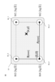
- FIG. 2 is a schematic diagram showing a measurement mechanism of a load measurement device according to an embodiment of the present disclosure.
- 3A and 3B are diagrams illustrating center of gravity swing and weight swing according to an embodiment of the present disclosure.
- FIG. 4 is a block diagram showing a hardware configuration of a measurement data management device according to an embodiment of the present disclosure.
- FIG. 5 is a block diagram showing the functional configuration of a measurement data management device according to an embodiment of the present disclosure.
- FIG. 6 is a diagram illustrating a user's ascending and descending states with respect to the load measuring device according to an embodiment of the present disclosure.
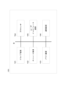
- FIG. 7 is a schematic diagram showing different trajectories of barycentric coordinates depending on the installation location according to an embodiment of the present disclosure.
- 8A and 8B are schematic diagrams showing different trajectories of barycentric coordinates depending on the arrangement of the load measuring device according to an embodiment of the present disclosure.
- 9A to 9D are diagrams showing trajectories of barycentric coordinate time series data according to an embodiment of the present disclosure.
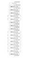
- FIG. 10 is a schematic diagram illustrating the architecture of a machine learning model according to an embodiment of the present disclosure.
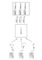
- FIG. 11 is a schematic diagram illustrating a machine learning model that generates feature data from barycenter coordinate time series data according to an embodiment of the present disclosure.
- FIG. 12 is a schematic diagram illustrating a machine learning model that generates feature data from barycenter coordinate time series data rotated by 180 degrees according to an embodiment of the present disclosure.
- FIG. 13 is a flowchart showing measurement data management processing according to an embodiment of the present disclosure.
- a measurement system that can automatically identify a user to be measured and manage measurement results in association with the user's identification information is disclosed.
- a measurement system includes a load measurement device (e.g., scale) that measures the weight of a user, and a measurement data management device (e.g., personal computers (PCs), information processing terminals such as smartphones and tablets).
- the load measuring device continues to measure the user's load on the platform at at least three measurement points from the time the user begins to rest on the platform with one foot until the time when both feet leave the platform.
- the load time series data for the period of time is sent to the measurement data management device.
- the measurement data management device Upon acquiring the load time series data from the load measuring device, the measurement data management device generates barycentric coordinate time series data of the user's load based on the acquired load time series data. It is known that the tendency of variation in the coordinates of a person's center of gravity when ascending or descending from a platform or the like has characteristics unique to each individual and can be used to identify individuals.
- the measurement data management device stores the barycenter coordinate time series data in advance in association with the user's identification information, and thereafter, when receiving the load time series data to be identified from the load measurement device, the measurement data management device stores the barycenter coordinate time series data in association with the user's identification information. Users can be automatically identified based on barycenter coordinate time series data.
- the measurement system 10 includes a load measurement device 50 and a measurement data management device 100 that is communicatively connected to the load measurement device 50.
- the load measuring device 50 is typically realized as a weight scale, measures the user's load while on a platform, and outputs load time series data indicating the measured load as a measurement result to a measurement data management device. Send to 100.
- the load measuring device 50 may include load sensors 52_1, 52_2, 52_3, and 52_4 (hereinafter, may be collectively referred to as load sensors 52) at four corners of a rectangular platform 51. good.
- Each load sensor 52_1, 52_2, 52_3, 52_4 measures the load W1, W2, W3, W4 [kg weight] of the user placed on the platform 51 at a predetermined sampling rate.
- the load measuring device 50 transmits the measured loads W1 ti , W2 ti , W3 ti , W4 ti [kg weight] to the measurement data management device 100 as load time series data.
- the load measurement device 50 may transmit the impedance values and the like measured by each load sensor 52 to the measurement data management device 100 as load time series data.
- the load measuring device 50 determines whether from time t1, when the user starts to rest on the platform 51 with one foot, when both of the user's feet are on the platform 51 and the load fluctuation is stabilized, or when both the user's feet have moved away from the platform 51.
- Time series data of the measurement results of each load sensor 52_1, 52_2, 52_3, 52_4 up to time tn (W1 t1 , W2 t1 , W3 t1 , W4 t1 ), (W1 t2 , W2 t2 , W3 t2 , W4 t2 ), ..., (W1 tn , W2 tn , W3 tn , W4 tn ) may be transmitted to the measurement data management device 100.
- the predetermined sampling rate may be a predetermined unit of time, such as 20 Hz, and the data length may correspond to a predetermined duration, such as 1 byte.
- the measurement data management device 100 can calculate the user's weight value as well as the user's center of gravity position (coordinates (x, y) in FIG. 2, etc.) based on the received load time series data.
- a change in the coordinates of the center of gravity that is, a swing of the center of gravity during a period when the user starts standing on the platform 51 with one foot and then stands still with both feet
- a trajectory as shown in FIG. 3A Further, changes in body weight values during the period, that is, body weight fluctuations, can be expressed as a trajectory as shown in FIG. 3B.
- center of gravity fluctuation and body weight fluctuation can be used to identify individuals, and in the following example, the measurement data management device 100 uses load time series data measured by the load measurement device 50 The user is automatically identified based on the calculated center of gravity fluctuation and/or body weight fluctuation, and the measured weight value of the user is stored in association with the user's identification information.
- the load measuring device 50 includes four load sensors 52_1, 52_2, 52_3, and 52_4, but the present disclosure is not necessarily limited to this.
- the load measuring device 50 may include at least three load sensors 52.
- the mounting table 51 does not necessarily have to be table-shaped, and may have a planar shape such as a mat.
- the measurement data management device 100 is typically realized by an information processing terminal such as a personal computer (PC), smartphone, or tablet, and is capable of wired/wireless communication with the load measurement device 50.
- the measurement data management device 100 acquires the load time series data of the user from the load measurement device 50
- the measurement data management device 100 calculates the center of gravity coordinate time series data of the load during the period when the user is on the stage based on the acquired load time series data.
- the barycentric coordinate time series data is stored in association with the user's identification information.
- the barycentric coordinate time series data #1 and #2 of user #1 and user #2 are transmitted to user #1 and user #2. They are initially registered in the user measurement data in association with each other.
- the measurement data management device 100 After user registration, when load time series data is acquired from the load measuring device 50, the measurement data management device 100 generates barycenter coordinate time series data from the acquired load time series data, and registers user #1 and user #2.
- the user #1 and the user #2 are automatically identified based on the generated barycenter coordinate time series data by referring to the barycenter coordinate time series data #1 and #2 that have been generated. After identifying the user, the measurement data management device 100 stores the measured weight value in the user measurement data in association with the identified user.
- the measurement data management device 100 uses a machine learning model trained to generate feature data from barycenter coordinate time series data to acquire barycenter coordinate time series data of the identification target, and It may be determined whether the barycenter coordinate time series data to be identified and the registered barycenter coordinate time series data belong to the same user, based on the degree of similarity between the barycenter coordinate time series data and the feature data of the barycenter coordinate time series data. .
- the load measuring device 50 transmits the measurement results of each load sensor 52 to the measurement data management device 100, but the present disclosure is not necessarily limited to this.
- the load measuring device 50 calculates the user's center of gravity coordinate time series data and/or weight time series data based on the measurement results of each load sensor 52, and calculates the user's center of gravity coordinate time series data and/or weight time series data.
- the data may be transmitted to the measurement data management device 100 as load time series data.
- the load measuring device 50 and the measurement data management device 100 do not necessarily need to be physically separated, and may be physically integrated as a measuring device.
- the measurement data management device 100 may be realized by a computing device such as a personal computer (PC), a smartphone, or a tablet, and may have a hardware configuration as shown in FIG. 4, for example. That is, the measurement data management device 100 includes a drive device 101, a storage device 102, a memory device 103, a processor 104, a user interface (UI) device 105, and a communication device 106 that are interconnected via a bus B.
- a computing device such as a personal computer (PC), a smartphone, or a tablet
- the measurement data management device 100 includes a drive device 101, a storage device 102, a memory device 103, a processor 104, a user interface (UI) device 105, and a communication device 106 that are interconnected via a bus B.
- UI user interface
- Programs or instructions for realizing various functions and processes to be described later in the measurement data management device 100 may be stored in a removable storage medium such as a CD-ROM (Compact Disk-Read Only Memory) or a flash memory.
- a program or instruction is installed from the storage medium into the storage device 102 or the memory device 103 via the drive device 101.
- the program or instructions do not necessarily need to be installed from a storage medium, and may be downloaded from any external device via a network or the like.
- the storage device 102 is realized by a hard disk drive or the like, and stores installed programs or instructions as well as files, data, etc. used to execute the programs or instructions.
- the memory device 103 is realized by random access memory, static memory, etc., and when a program or instruction is started, reads the program or instruction, data, etc. from the storage device 102 and stores it.
- the storage device 102, the memory device 103, and the removable storage medium may be collectively referred to as a non-transitory storage medium.
- the processor 104 may be realized by one or more CPUs (Central Processing Units), GPUs (Graphics Processing Units), processing circuits, etc. that may be configured from one or more processor cores, and the memory device 1 on 03 Various functions and processes of the measurement data management device 100, which will be described later, are executed according to stored programs, instructions, and data such as parameters necessary to execute the programs or instructions.
- CPUs Central Processing Units
- GPUs Graphics Processing Units
- processing circuits etc.
- the processor 104 may be realized by one or more CPUs (Central Processing Units), GPUs (Graphics Processing Units), processing circuits, etc. that may be configured from one or more processor cores, and the memory device 1 on 03 Various functions and processes of the measurement data management device 100, which will be described later, are executed according to stored programs, instructions, and data such as parameters necessary to execute the programs or instructions.
- the user interface (UI) device 105 may include input devices such as a keyboard, mouse, camera, and microphone, output devices such as a display, speaker, headset, and printer, and input/output devices such as a touch panel. It realizes an interface with the data management device 100. For example, a user operates a GUI (Graphical User Interface) displayed on a display or a touch panel using a keyboard, a mouse, etc., to operate the measurement data management device 100.
- GUI Graphic User Interface
- the communication device 106 is realized by various communication circuits that perform wired and/or wireless communication processing with communication networks such as external devices, the Internet, LAN (Local Area Network), and cellular networks.
- communication networks such as external devices, the Internet, LAN (Local Area Network), and cellular networks.
- the hardware configuration described above is merely an example, and the measurement data management device 100 according to the present disclosure may be realized by any other suitable hardware configuration.
- FIG. 5 is a block diagram showing the functional configuration of the measurement data management device 100 according to an embodiment of the present disclosure.
- the measurement data management device 100 includes a load data acquisition section 110, a center of gravity data generation section 120, and a measurement data management section 130.
- one or more functional units of the load data acquisition unit 110, the center of gravity data generation unit 120, and the measurement data management unit 130 are stored in one or more memory devices 103 by one or more processors 104. This may be realized by executing a program or instructions.
- the load data acquisition unit 110 acquires load data generated by measuring the load on the platform 51 on which the user is placed at at least three measurement locations. Specifically, the load data acquisition unit 110 determines from the load measuring device 50 that from time t1 when the user starts to rest on the platform 51 with one foot, both of the user's feet have left the platform 51 or the user has placed the platform 51 on the platform 51.
- the weight fluctuation caused by the movement may indicate a rapid increase in the load value, as shown in the figure.
- the center of gravity data generation unit 120 generates time series data of the center of gravity coordinates of the load during the period when the user is placed on the stage 51 based on the load data. Specifically, (W1 t1 , W2 t1 , W3 t1 , W4 t1 ), (W1 t2 , W2 t2 , W3 t2 , W4 t2 ), . . .
- y ti [mm] B ⁇ (W1 ti + W3 ti )/(W1 ti +W2 ti W3 ti +W4 ti ).
- the barycenter data generation unit 120 generates barycenter coordinate time series data (x t1 , y t2 ) , (x t2 , y t2 ), ..., ( x tn , y tn ).
- the center of gravity data generation unit 120 may also generate weight time series data z t1 , z t2 , . . . , z tn based on the weight value z ti at each time ti.
- the barycenter data generation unit 120 may generate a two-dimensional image showing the locus of barycenter coordinates as barycenter coordinate time series data. Furthermore, the center of gravity data generation unit 120 may generate an image showing the center of gravity time series data associated with the weight time series data.
- the weight time series data may be normalized to a range of 0 to 1, and the normalized weight value at each point in time may be associated with the centroid coordinates at that point in time.
- the image of the trajectory may be colored or grayscaled depending on the normalized weight value.
- the measurement data management unit 130 stores barycenter coordinate time series data in association with user identification information. Specifically, the measurement data management unit 130 registers the barycenter coordinate time series data of the user as user measurement data in association with the identification information of the user to be registered. For example, when starting to use the measurement system 10, the measurement data management unit 130 may initially associate the user's identification information with the user's barycenter coordinate time series data and register the user measurement data. .
- the measurement data management unit 130 stores the barycenter coordinate time series data generated from the acquired load data as the center of gravity of the registered user. Determine which of the coordinate time series data matches. If the generated barycenter coordinate time series data matches the barycenter coordinate time series data of a registered user, the measurement data management unit 130 stores the weight value calculated from the load data in association with the user's identification information. do.
- the measurement data management unit 130 determines that a new user is on the platform 51, and You may also inquire whether to register as a new user. When instructed to register the user as a new user, the measurement data management unit 130 registers the generated barycenter coordinate time series data in the user measurement data in association with the identification information of the user.
- the measurement data management unit 130 may inquire whether the installation position of the platform 51 has been changed. For example, as shown in FIG. 7, if the platform 51 is placed at the entrance to a bathroom, it is assumed that the user steps on the platform 51 and then goes straight ahead into the bathroom. On the other hand, when the platform 51 is placed below the washstand, it is assumed that the user steps backwards and gets off the platform 51 after standing on the platform 51 . As shown in FIG. 7, due to the difference in the movement of moving up and down to the platform 51, the time-series data of the coordinate position of the center of gravity of the same user regarding each movement of movement may also differ, as shown in FIG.
- the measurement data management unit 130 inquires of the user whether the discrepancy between the generated barycenter coordinate time series data and the registered user's barycenter coordinate time series data is due to a change in the installation position of the mounting table 51. You can. When notified that the installation position of the platform 51 has been changed, the measurement data management unit 130 notifies the user to specify the user of the generated barycenter coordinate time series data, and associates it with the identification information of the specified user. Then, the installation location information indicating the installation location of the platform 51 and the barycentric coordinate time series data may be registered in the user measurement data.
- the measurement data management unit 130 generates barycenter coordinate time series data obtained by rotating the barycenter coordinate time series data by 180 degrees, associates the barycenter coordinate time series data with the user's identification information, and generates barycenter coordinate time series data by rotating the barycenter coordinate time series data by 180 degrees.
- Series data may be stored as user measurement data.
- the platform 51 may have an orientation depending on the placement of the load sensor 52, as described with reference to FIG.
- the barycenter coordinate time series data for the case where the user is placed on the platform 51 in the moving direction as shown in FIG. 8A and the case where the user is placed on the platform 51 in the moving direction as shown in FIG. 8B are as follows.
- the measurement data management unit 130 links the barycenter coordinate time series data of the user with the user's identification information. , barycenter coordinate time series data obtained by rotating the barycenter coordinate time series data by 180 degrees may be stored.
- the measurement data management unit 130 may store the barycentric coordinate time series data in association with the weight time series data.
- the center of gravity data generation unit 120 generates weight time series data indicating fluctuations in the user's weight value during the period when the user is on the platform 51 based on the load data, and uses the generated weight time series data. It is possible to generate barycenter coordinate time series data associated with series data.
- the measurement data management unit 130 may store the barycentric coordinate time series data associated with the weight time series data.
- the association may be performed by superimposing weight time series data on barycenter coordinate time series data.
- the center of gravity data generation unit 120 may normalize the weight time series data of each user within the range of 0 to 1, and associate the normalized value at each time point with the coordinates of the center of gravity at that time point.
- the barycenter data generation unit 120 quantizes the normalized values of 0 to 1 to any quantization level, assigns a color or gray scale to each level, and creates a trajectory of the barycenter coordinate time series data. May be colored.
- the barycenter coordinate time series data associated with the weight time series data can be expressed as an image showing the locus of the barycenter coordinates in color or gray scale, as shown in FIGS. 9A to 9D. can.
- the center of gravity data generation unit 120 generates weight time series data at four weight levels (for example, for weight values w normalized to 0 to 1, 0 ⁇ w ⁇ 0.25, 0.25 ⁇ w ⁇ 0. 5, 0.5 ⁇ w ⁇ 0.75, 0.75 ⁇ w ⁇ 1, etc.), and colors #1 to #4 may be assigned to each quantization level.
- the barycenter data generation unit 120 assigns colors #1 to #4 to the trajectory as shown in FIG. 9B.
- An assigned color image may be generated.
- the barycenter data generation unit 120 assigns colors #1 to #4 to the trajectory, as shown in FIG.
- each quantization level of weight time series data does not necessarily need to be depicted in color or gray scale, and any other superimposition method that can identify each quantization level of normalized weight values may be applied. may be done.
- the measurement data management unit 130 may store an image showing the locus of the center of gravity coordinates that has been colored or grayscaled in this manner as the barycenter coordinate time series data associated with the weight time series data. Furthermore, the measurement data management unit 130 stores an image showing a trajectory obtained by rotating the trajectory of each user's colorized or grayscale center of gravity coordinates by 180 degrees in association with the identification information of the user. You can.
- the measurement data management device 100 may utilize a machine learning model trained to convert barycenter coordinate time series data into feature data.
- the machine learning model may be any known machine learning model that is trained to receive as input an image showing a trajectory of barycenter coordinate time series data and output the feature amount of the image.
- the machine learning model may be any type of machine learning model that outputs similar feature amounts for similar trajectories.
- the machine learning model may be configured by an architecture as shown in FIG. 10 (eg, EfficientNet B0, etc.).
- the machine learning model is a machine learning model that accepts as input an image showing a colored or grayscaled trajectory of barycenter coordinate time series data associated with weight time series data, and outputs the feature amount of the image. There may be.
- the machine learning model may be provided in the measurement data management device 100 or may be provided on the cloud.
- the measurement data management unit 130 when registering users #1, #2, and #3 in user measurement data, stores trajectories of barycenter coordinate time series data of users #1, #2, and #3. , or an image showing a colored or grayscaled trajectory of barycenter coordinate time series data associated with weight time series data, is input to the machine learning model, and each feature data #1, #2, #3 may be acquired, and the acquired feature data #1, #2, #3 may be stored as user measurement data in association with the identification information of users #1, #2, #3.
- the measurement data management unit 130 generates images showing trajectories obtained by rotating the trajectories of the barycenter coordinate time series data of users #1, #2, and #3 by 180 degrees, or weight time series data of users #1, #2, and #3. It is also possible to acquire images showing trajectories obtained by rotating 180 degrees the colorized or grayscaled trajectories of the barycenter coordinate time series data associated with , and input these images to the machine learning model. Then, the measurement data management unit 130 acquires the respective feature amount data #1, #2, #3 from the machine learning model, associates it with the identification information of users #1, #2, and #3, and Data #1, #2, and #3 may be stored as user measurement data.
- the measurement data management unit 130 utilizes a machine learning model to calculate It can be determined to which user registered in the user measurement data the unknown load data to be identified belongs.
- the measurement data management unit 130 inputs the barycentric coordinate time series data generated from the load data of the identification target to the machine learning model, and acquires the feature amount data from the machine learning model.
- the measurement data management unit 130 registers feature data whose similarity with the acquired feature data (for example, cosine distance between two feature vectors, etc.) is greater than a predetermined threshold as user measurement data. If so, the acquired feature data is determined to be that of the user of the registered feature data, and the weight value calculated from the load data of the identification target is linked to the identified user's identification information. It may also be recorded in user measurement data.
- the measurement data management unit 130 determines that the acquired feature data belongs to an unregistered user, and either registers the unregistered user as a new user or You may also inquire. When instructed to register the user as a new user, the measurement data management unit 130 registers the feature data and/or barycenter coordinate time series data in the user measurement data in association with the user's identification information. You can.
- the measurement data management unit 130 determines that the installation location of the platform 51 has been changed, You may also inquire whether the installation location of the platform 51 has been changed. When the installation location is changed and it is notified that the load data belongs to a registered user, the measurement data management unit 130 updates the installation location information with the changed installation location and also updates the identification information of the user.
- the feature amount data and/or the barycenter coordinate time series data may be registered in the user measurement data in association with the above.
- the measurement system 10 it is possible to automatically identify a user who is placed on the load measurement device 50, and to record load data indicating the weight or load of the user in association with the user's identification information.
- measurement data management processing is executed by the measurement data management device 100 described above, and more specifically, one or more processors 104 of the measurement data management device 100 execute one or more processors 104 stored in one or more memory devices 103. This may be realized by executing a program or instructions.
- FIG. 13 is a flowchart showing measurement data management processing according to an embodiment of the present disclosure.
- the measurement data management device 100 acquires user load data. Specifically, the measurement data management device 100 acquires load data indicating the load of the user on the platform 51 from the load measurement device 50.
- the load data is, for example, time series data of load values (W1 t1 , W2 t1 , W3 t1 , W4 t1 ), (W1 t2 , W2 t2 , W3 t2 , W4 t2 ), ..., (W1 tn , W2 tn , W3 tn , W4 tn ).
- the measurement data management device 100 stores the barycentric coordinate time series data (x t1 , y t1 ), (x t2 , y t2 ), . ..., (x tn , y tn ) and weight time series data z t1 , z t2 , . . . , z tn may be generated.
- the measurement data management device 100 generates feature data from the barycenter coordinate time series data using a machine learning model trained to extract feature quantities from the barycenter coordinate time series data. Specifically, the measurement data management device 100 uses a machine learning model trained to output a feature quantity from an image showing a locus of the barycenter coordinates of the barycenter coordinate time series data, An image showing a locus of barycentric coordinates derived from coordinate time series data may be input to a machine learning model, and feature amount data of the image may be acquired from the machine learning model.
- the measurement data management device 100 uses a machine learning model trained to extract feature quantities from the barycenter coordinate time series data and weight time series data to extract features from the barycenter coordinate time series data and weight time series data.
- Feature data may also be generated.
- the measurement data management device 100 generates an image by associating weight time series data with the barycenter coordinate trajectory of the barycenter coordinate time series data, inputs the generated image to a machine learning model, and performs machine learning.
- the feature amount data of the image may be acquired from the model.
- An image generated by associating weight time series data with a locus of barycenter coordinates of barycenter coordinate time series data may be obtained, for example, by synchronizing the barycenter coordinate time series data and a weight time series image with respect to time.
- it may be an image generated by colorizing or gray-scaling the locus of the center of gravity coordinates according to each level of the weight value with respect to time.
- step S104 the measurement data management device 100 determines whether the acquired feature amount data has been registered in the user measurement data. Specifically, the degree of similarity between the feature amount acquired in step S103 and the feature amount of any user registered in the user measurement data (for example, the cosine distance between two feature vectors, etc.) is set to a predetermined threshold value. If it is larger (step S104: YES), the measurement data management device 100 determines that the acquired load data belongs to a registered user, and in step S105, the measurement data management device 100 determines that the acquired load data belongs to a registered user, and in step S105, extracts the load data from the load data in association with the user's identification information. Store the derived weight value.
- the measurement data management device 100 It is determined that the acquired load data belongs to an unregistered user, and the user is inquired to register the user in the user measurement data, or if the installation location of the load measuring device 50 may have been changed. The determination may be made and the user may be asked whether the installation location of the load measuring device 50 has been changed.
- the measurement data management device 100 registers the feature amount data acquired in step S103 in the user measurement data in association with the identification information of the user in step S106. You can.
- the measurement data management device 100 associates the identification information specified by the user with the installation location information indicating the changed installation location, and Weight values derived from the data may be stored.
- a load data acquisition unit that acquires load data generated by measuring the load on the platform on which the user is placed at at least three measurement points; a center-of-gravity data generation unit that generates first time-series data of the center-of-gravity coordinates of the load during a period in which the user is on the loading table, based on the load data; a measurement data management unit that stores the first time series data in association with the user's identification information;
- a measurement data management device having: (Additional note 2) The measurement data management unit generates second time series data by rotating the first time series data by 180 degrees, and stores the second time series data in association with identification information of the user.
- the measurement data management device according to Supplementary Note 1.
- the measurement data management device according to 2.
- the measurement data management device according to any one of Supplementary Notes 1 to 3, wherein the measurement data management unit stores installation location information indicating an installation location of the recording stand.
- the measurement data management unit uses a trained machine learning model to generate first feature data representing the first time series data and second feature data representing the second time series data.
- the measurement data management device according to any one of Supplementary Notes 2 to 4, wherein the measurement data management device acquires and stores the first feature data and the second feature data in association with the user's identification information.
- the measurement data management unit Upon acquiring the time-series data of the centroid coordinates of the user to be identified, the measurement data management unit acquires feature data of the target to be identified that indicates the acquired time-series data, and combines the feature data of the target user with the first and the second feature data, and identifies the user to be identified based on the comparison result. (Appendix 7) If the degree of similarity between the feature amount of the identification target and the first feature data and the second feature data is less than or equal to a predetermined threshold, the measurement data management unit converts the user to be identified into a new user.
- the measurement data management device according to appendix 6 or 7, which registers or inquires as.
- the measurement data management unit changes the installation position of the stand.
- the measurement data management device according to supplementary note 6 or 7, which inquires whether the measurement data has been measured.
- the measurement data management unit generates third time-series data indicating third time-series data generated by associating the first time-series data and the body weight time-series data using a trained machine learning model.
- the measurement data management device according to any one of appendices 3 to 8, which acquires feature data and stores the third feature data in association with identification information of the user.
- a load measuring device A measurement data management device; has The load measurement device measures the load on the platform on which the user is placed at at least three measurement locations, and transmits load data generated based on the measured load to the measurement data management device, The measurement data management device generates, based on the load data, first time-series data of the barycentric coordinates of the load during the period when the user is on the table, and associates the data with the user's identification information. , a measurement system that stores the first time series data.
- the measurement system according to the present disclosure can be utilized in a weight scale shared by multiple users.
- measurement system 50 load measurement device 100 measurement data management device 110 load data acquisition unit 120 center of gravity data generation unit 130 measurement data management unit
Landscapes
- Health & Medical Sciences (AREA)
- Life Sciences & Earth Sciences (AREA)
- Engineering & Computer Science (AREA)
- Physics & Mathematics (AREA)
- Medical Informatics (AREA)
- Pathology (AREA)
- Veterinary Medicine (AREA)
- Heart & Thoracic Surgery (AREA)
- Molecular Biology (AREA)
- Public Health (AREA)
- General Physics & Mathematics (AREA)
- General Health & Medical Sciences (AREA)
- Theoretical Computer Science (AREA)
- Animal Behavior & Ethology (AREA)
- Surgery (AREA)
- Biophysics (AREA)
- Biomedical Technology (AREA)
- Software Systems (AREA)
- Dentistry (AREA)
- Evolutionary Computation (AREA)
- Artificial Intelligence (AREA)
- Computer Vision & Pattern Recognition (AREA)
- Mathematical Physics (AREA)
- General Engineering & Computer Science (AREA)
- Computing Systems (AREA)
- Physiology (AREA)
- Data Mining & Analysis (AREA)
- Oral & Maxillofacial Surgery (AREA)
- Measurement Of The Respiration, Hearing Ability, Form, And Blood Characteristics Of Living Organisms (AREA)
- Management, Administration, Business Operations System, And Electronic Commerce (AREA)
Priority Applications (1)
| Application Number | Priority Date | Filing Date | Title |
|---|---|---|---|
| JP2024536774A JP7780779B2 (ja) | 2022-07-25 | 2023-03-24 | 測定データ管理装置、測定データ管理方法、プログラム及び測定システム |
Applications Claiming Priority (2)
| Application Number | Priority Date | Filing Date | Title |
|---|---|---|---|
| JP2022-118071 | 2022-07-25 | ||
| JP2022118071 | 2022-07-25 |
Publications (1)
| Publication Number | Publication Date |
|---|---|
| WO2024024165A1 true WO2024024165A1 (ja) | 2024-02-01 |
Family
ID=89705878
Family Applications (1)
| Application Number | Title | Priority Date | Filing Date |
|---|---|---|---|
| PCT/JP2023/011804 Ceased WO2024024165A1 (ja) | 2022-07-25 | 2023-03-24 | 測定データ管理装置、測定データ管理方法、プログラム及び測定システム |
Country Status (2)
| Country | Link |
|---|---|
| JP (1) | JP7780779B2 (https=) |
| WO (1) | WO2024024165A1 (https=) |
Citations (6)
| Publication number | Priority date | Publication date | Assignee | Title |
|---|---|---|---|---|
| JP2012057969A (ja) * | 2010-09-06 | 2012-03-22 | Omron Healthcare Co Ltd | 体重計測システム |
| JP2014140640A (ja) * | 2012-12-26 | 2014-08-07 | Tanita Corp | 重心動揺計、重心動揺評価方法、個人認証装置および個人認証方法 |
| WO2018179325A1 (ja) * | 2017-03-31 | 2018-10-04 | 三菱電機株式会社 | 登録装置、認証装置、個人認証システム及び個人認証方法、並びにプログラム及び記録媒体 |
| WO2020240752A1 (ja) * | 2019-05-29 | 2020-12-03 | 日本電気株式会社 | 情報処理装置、体重推定装置、体重推定システム、情報処理方法及び記憶媒体 |
| JP7028500B2 (ja) * | 2019-12-27 | 2022-03-02 | 株式会社Rabo | 動物用重量測定システム及び方法 |
| JP2022148871A (ja) * | 2021-03-24 | 2022-10-06 | 太陽誘電株式会社 | 特定装置 |
-
2023
- 2023-03-24 WO PCT/JP2023/011804 patent/WO2024024165A1/ja not_active Ceased
- 2023-03-24 JP JP2024536774A patent/JP7780779B2/ja active Active
Patent Citations (6)
| Publication number | Priority date | Publication date | Assignee | Title |
|---|---|---|---|---|
| JP2012057969A (ja) * | 2010-09-06 | 2012-03-22 | Omron Healthcare Co Ltd | 体重計測システム |
| JP2014140640A (ja) * | 2012-12-26 | 2014-08-07 | Tanita Corp | 重心動揺計、重心動揺評価方法、個人認証装置および個人認証方法 |
| WO2018179325A1 (ja) * | 2017-03-31 | 2018-10-04 | 三菱電機株式会社 | 登録装置、認証装置、個人認証システム及び個人認証方法、並びにプログラム及び記録媒体 |
| WO2020240752A1 (ja) * | 2019-05-29 | 2020-12-03 | 日本電気株式会社 | 情報処理装置、体重推定装置、体重推定システム、情報処理方法及び記憶媒体 |
| JP7028500B2 (ja) * | 2019-12-27 | 2022-03-02 | 株式会社Rabo | 動物用重量測定システム及び方法 |
| JP2022148871A (ja) * | 2021-03-24 | 2022-10-06 | 太陽誘電株式会社 | 特定装置 |
Also Published As
| Publication number | Publication date |
|---|---|
| JP7780779B2 (ja) | 2025-12-05 |
| JPWO2024024165A1 (https=) | 2024-02-01 |
Similar Documents
| Publication | Publication Date | Title |
|---|---|---|
| Skals et al. | A musculoskeletal model driven by dual Microsoft Kinect Sensor data | |
| US20180121784A1 (en) | Conversation control system | |
| JP6881451B2 (ja) | 歩行状態判定装置、歩行状態判定システム、歩行状態判定方法及びプログラム | |
| US11341423B2 (en) | Information processing apparatus, artificial intelligence selection method, and artificial intelligence selection program | |
| KR20190056116A (ko) | 디지털 재활치료시스템의 훈련비율 추출방법 및 프로그램 | |
| JP2005175806A5 (https=) | ||
| US11925458B2 (en) | Motion state monitoring system, training support system, motion state monitoring method, and program | |
| WO2021233011A1 (zh) | 一种体成分检测方法、设备和计算机可读存储介质 | |
| EP2993554A1 (en) | Method for matching multiple devices, device for enabling matching thereof and server system | |
| JP2022100238A (ja) | 人の姿勢に基づきマルチカメラシステムを較正する方法及び機器 | |
| KR20220063847A (ko) | 대상자의 보행 패턴을 식별하는 방법 및 이를 수행하는 전자 장치 | |
| CN115004265A (zh) | 信息处理装置以及判断结果输出方法 | |
| JP2020501285A (ja) | コンピュータを用いた抽出順序決定方法及びプログラム | |
| JP2007510137A5 (https=) | ||
| WO2024024165A1 (ja) | 測定データ管理装置、測定データ管理方法、プログラム及び測定システム | |
| CN113962766B (zh) | 一种用于简单混合型隐私保护场景的商品推荐方法及系统 | |
| WO2020149044A1 (ja) | パラメータ選定装置、パラメータ選定方法、およびパラメータ選定プログラム | |
| US20240169559A1 (en) | Analysis device, analysis method, analysis program, and generation device | |
| JP4950865B2 (ja) | センサノード制御システム及び方法 | |
| Oji et al. | Weight estimation of lifted object from body motions using neural network | |
| US12277763B2 (en) | Load estimation apparatus and method | |
| CN118170249A (zh) | 眼动跟踪系统及对应的方法 | |
| KR101896510B1 (ko) | 훈련비율 결정방법 및 프로그램 | |
| CN117630784A (zh) | 十参数三轴磁传感器标定方法和装置 | |
| JP7016101B2 (ja) | 情報処理システム、情報処理装置、プログラム、及び情報処理方法 |
Legal Events
| Date | Code | Title | Description |
|---|---|---|---|
| 121 | Ep: the epo has been informed by wipo that ep was designated in this application |
Ref document number: 23845905 Country of ref document: EP Kind code of ref document: A1 |
|
| WWE | Wipo information: entry into national phase |
Ref document number: 2024536774 Country of ref document: JP |
|
| NENP | Non-entry into the national phase |
Ref country code: DE |
|
| 122 | Ep: pct application non-entry in european phase |
Ref document number: 23845905 Country of ref document: EP Kind code of ref document: A1 |