WO2024024109A1 - 積層造形装置および積層造形方法 - Google Patents
積層造形装置および積層造形方法 Download PDFInfo
- Publication number
- WO2024024109A1 WO2024024109A1 PCT/JP2022/029362 JP2022029362W WO2024024109A1 WO 2024024109 A1 WO2024024109 A1 WO 2024024109A1 JP 2022029362 W JP2022029362 W JP 2022029362W WO 2024024109 A1 WO2024024109 A1 WO 2024024109A1
- Authority
- WO
- WIPO (PCT)
- Prior art keywords
- additive manufacturing
- electron beam
- laser beam
- powder material
- irradiation
- Prior art date
- Legal status (The legal status is an assumption and is not a legal conclusion. Google has not performed a legal analysis and makes no representation as to the accuracy of the status listed.)
- Ceased
Links
Images




Classifications
-
- B—PERFORMING OPERATIONS; TRANSPORTING
- B22—CASTING; POWDER METALLURGY
- B22F—WORKING METALLIC POWDER; MANUFACTURE OF ARTICLES FROM METALLIC POWDER; MAKING METALLIC POWDER; APPARATUS OR DEVICES SPECIALLY ADAPTED FOR METALLIC POWDER
- B22F10/00—Additive manufacturing of workpieces or articles from metallic powder
- B22F10/20—Direct sintering or melting
- B22F10/28—Powder bed fusion, e.g. selective laser melting [SLM] or electron beam melting [EBM]
-
- B—PERFORMING OPERATIONS; TRANSPORTING
- B22—CASTING; POWDER METALLURGY
- B22F—WORKING METALLIC POWDER; MANUFACTURE OF ARTICLES FROM METALLIC POWDER; MAKING METALLIC POWDER; APPARATUS OR DEVICES SPECIALLY ADAPTED FOR METALLIC POWDER
- B22F10/00—Additive manufacturing of workpieces or articles from metallic powder
- B22F10/30—Process control
- B22F10/34—Process control of powder characteristics, e.g. density, oxidation or flowability
-
- B—PERFORMING OPERATIONS; TRANSPORTING
- B22—CASTING; POWDER METALLURGY
- B22F—WORKING METALLIC POWDER; MANUFACTURE OF ARTICLES FROM METALLIC POWDER; MAKING METALLIC POWDER; APPARATUS OR DEVICES SPECIALLY ADAPTED FOR METALLIC POWDER
- B22F10/00—Additive manufacturing of workpieces or articles from metallic powder
- B22F10/30—Process control
- B22F10/36—Process control of energy beam parameters
- B22F10/362—Process control of energy beam parameters for preheating
-
- B—PERFORMING OPERATIONS; TRANSPORTING
- B22—CASTING; POWDER METALLURGY
- B22F—WORKING METALLIC POWDER; MANUFACTURE OF ARTICLES FROM METALLIC POWDER; MAKING METALLIC POWDER; APPARATUS OR DEVICES SPECIALLY ADAPTED FOR METALLIC POWDER
- B22F10/00—Additive manufacturing of workpieces or articles from metallic powder
- B22F10/80—Data acquisition or data processing
- B22F10/85—Data acquisition or data processing for controlling or regulating additive manufacturing processes
-
- B—PERFORMING OPERATIONS; TRANSPORTING
- B22—CASTING; POWDER METALLURGY
- B22F—WORKING METALLIC POWDER; MANUFACTURE OF ARTICLES FROM METALLIC POWDER; MAKING METALLIC POWDER; APPARATUS OR DEVICES SPECIALLY ADAPTED FOR METALLIC POWDER
- B22F12/00—Apparatus or devices specially adapted for additive manufacturing; Auxiliary means for additive manufacturing; Combinations of additive manufacturing apparatus or devices with other processing apparatus or devices
- B22F12/40—Radiation means
- B22F12/44—Radiation means characterised by the configuration of the radiation means
- B22F12/45—Two or more
-
- B—PERFORMING OPERATIONS; TRANSPORTING
- B33—ADDITIVE MANUFACTURING TECHNOLOGY
- B33Y—ADDITIVE MANUFACTURING, i.e. MANUFACTURING OF THREE-DIMENSIONAL [3D] OBJECTS BY ADDITIVE DEPOSITION, ADDITIVE AGGLOMERATION OR ADDITIVE LAYERING, e.g. BY 3D PRINTING, STEREOLITHOGRAPHY OR SELECTIVE LASER SINTERING
- B33Y10/00—Processes of additive manufacturing
-
- B—PERFORMING OPERATIONS; TRANSPORTING
- B33—ADDITIVE MANUFACTURING TECHNOLOGY
- B33Y—ADDITIVE MANUFACTURING, i.e. MANUFACTURING OF THREE-DIMENSIONAL [3D] OBJECTS BY ADDITIVE DEPOSITION, ADDITIVE AGGLOMERATION OR ADDITIVE LAYERING, e.g. BY 3D PRINTING, STEREOLITHOGRAPHY OR SELECTIVE LASER SINTERING
- B33Y30/00—Apparatus for additive manufacturing; Details thereof or accessories therefor
-
- B—PERFORMING OPERATIONS; TRANSPORTING
- B33—ADDITIVE MANUFACTURING TECHNOLOGY
- B33Y—ADDITIVE MANUFACTURING, i.e. MANUFACTURING OF THREE-DIMENSIONAL [3D] OBJECTS BY ADDITIVE DEPOSITION, ADDITIVE AGGLOMERATION OR ADDITIVE LAYERING, e.g. BY 3D PRINTING, STEREOLITHOGRAPHY OR SELECTIVE LASER SINTERING
- B33Y40/00—Auxiliary operations or equipment, e.g. for material handling
- B33Y40/10—Pre-treatment
-
- Y—GENERAL TAGGING OF NEW TECHNOLOGICAL DEVELOPMENTS; GENERAL TAGGING OF CROSS-SECTIONAL TECHNOLOGIES SPANNING OVER SEVERAL SECTIONS OF THE IPC; TECHNICAL SUBJECTS COVERED BY FORMER USPC CROSS-REFERENCE ART COLLECTIONS [XRACs] AND DIGESTS
- Y02—TECHNOLOGIES OR APPLICATIONS FOR MITIGATION OR ADAPTATION AGAINST CLIMATE CHANGE
- Y02P—CLIMATE CHANGE MITIGATION TECHNOLOGIES IN THE PRODUCTION OR PROCESSING OF GOODS
- Y02P10/00—Technologies related to metal processing
- Y02P10/25—Process efficiency
Definitions
- the present invention relates to an additive manufacturing apparatus and an additive manufacturing method.
- Patent Document 1 discloses an additive manufacturing apparatus that uses a low-energy electron beam as a heating beam and a high-energy electron beam as a modeling beam. It has also been suggested that one of the heating beam and the shaping beam be an electron beam and the other a laser beam.
- the technology described in the above document does not describe which of the heating beam and the shaping beam should be an electron beam or a laser beam. That is, the description in the above-mentioned document does not even suggest an effective combination of an electron beam and a laser beam.
- An object of the present invention is to provide a technology that solves the above problems.
- the additive manufacturing method includes: An additive manufacturing method using an electron beam and a laser beam, the method comprising: In order to make the additively manufactured powder material into a conductive state by bonding the powders with each other through an oxide film layer on the powder surface while remaining in a solid phase without neck formation or liquid phase, the additively manufactured powder material is placed at a position scanned by the electron beam. a step of pre-irradiating with the laser beam; scanning and melting the additive manufacturing powder material in the electrically conductive state with the electron beam in order to model the additive manufacturing object; including.
- the additive manufacturing apparatus includes: An additive manufacturing device that performs additive manufacturing using an electron beam and a laser beam, In order to make the additively manufactured powder material into a conductive state by bonding the powders with each other through an oxide film layer on the powder surface while remaining in a solid phase without neck formation or liquid phase, the additively manufactured powder material is placed at a position scanned by the electron beam. a laser beam irradiation unit that irradiates the laser beam with the laser beam in advance; an electron beam irradiation unit that scans and melts the layered building powder material in the conductive state with the electron beam in order to form a layered object; Equipped with.
- effective additive manufacturing can be performed by combining a laser beam and an electron beam.
- FIG. 1 is a block diagram showing a configuration of a layered manufacturing apparatus according to a first embodiment and a flowchart showing an operation procedure of the layered manufacturing apparatus. It is a block diagram showing the functional composition of the layered manufacturing device concerning a 2nd embodiment. It is a block diagram showing the hardware configuration of the layered manufacturing device concerning a 2nd embodiment. It is a block diagram showing the functional composition of the control part of the layered manufacturing device concerning a 2nd embodiment.
- FIG. 7 is a diagram showing the configuration of a database and a calibration table according to a second embodiment. It is a flow chart which shows the processing procedure of the control part of the layered manufacturing device concerning a 2nd embodiment.
- FIG. 1 is a block diagram showing a configuration of a layered manufacturing apparatus according to a first embodiment and a flowchart showing an operation procedure of the layered manufacturing apparatus. It is a block diagram showing the functional composition of the layered manufacturing device concerning a 2nd embodiment. It is a block diagram showing the hardware configuration of the layered manufacturing device
- 2 is a diagram showing melt pulls during layered manufacturing using an electron beam and melt pulls during layered manufacturing using a laser beam. It is a block diagram showing the functional composition of the control part of the layered manufacturing device concerning a 3rd embodiment. It is a figure which shows the structure of the target material table based on 3rd Embodiment. It is a flowchart which shows the processing procedure of the control part of the layered manufacturing apparatus concerning 3rd Embodiment.
- a layered manufacturing apparatus 100 as a first embodiment of the present invention will be described using FIG. 1.
- the additive manufacturing apparatus 100 is an apparatus that melts additive manufacturing powder material 103 to create a additive manufacturing body.
- the additive manufacturing apparatus 100 is an additive manufacturing apparatus that performs additive manufacturing using an electron beam 121 and a laser beam 111, and includes a laser beam irradiation section 101 and an electron beam irradiation section 102. .
- the laser beam irradiation unit 101 scans the additively manufactured powder material with the electron beam 121 in order to bond the powders together and make them conductive through the oxide film layer on the powder surface while the powder material remains in a solid phase without neck formation or liquid phase.
- the layered modeling powder material 103 at the position 131 is irradiated with the laser beam 111 in advance.
- the electron beam irradiation unit 102 scans and melts the conductive layered building powder material 132 with the electron beam 121 in order to model a layered object.
- the layered manufacturing method S100 in FIG. 1 is a layered manufacturing method that performs layered manufacturing using an electron beam 121 and a laser beam 111, and includes step S101 and step S102.
- step S101 the layered additive manufacturing powder material is placed in a position 131 scanned by the electron beam 121 in order to bond the powders together using the oxide film layer on the powder surface and make the powder conductive while remaining in a solid phase without neck formation or liquid phase.
- the additive manufacturing powder material 103 is irradiated with a laser beam 111 in advance.
- step S102 in order to model a laminate-molded object, the laminate-molding powder material 132 in a conductive state is scanned with an electron beam 121 and melted.
- the relationship between the scanning positions of the electron beam and the laser beam is not limited to that shown in FIG. Any relationship may be used as long as the additive manufacturing powder material, which has been physically bonded and turned into a conductive state by laser beam irradiation, can be melted by an electron beam.
- effective additive manufacturing can be performed by combining a laser beam and an electron beam.
- the additive manufacturing method and the additive manufacturing apparatus according to the present embodiment irradiate the additive manufacturing powder material at a position scanned by the electron beam with a laser beam in advance to physically bind the additive manufacturing powder material and make it conductive. Then, by scanning and melting the physically bonded and electrically conductive layered building powder material with an electron beam, a layered object is formed. Therefore, additive manufacturing is performed to suppress the generation of smoke and pores in the molten pool. Furthermore, by calibrating the laser beam irradiation beam diameter, the electron beam irradiation beam diameter, the laser beam scanning position, and the electron beam scanning position before additive manufacturing, higher quality additive manufacturing objects can be produced. Manufacture.
- PBF-LB method a method that uses laser beam (LB) irradiation
- EB method electron beam irradiation
- PBF-EB method a method that uses electron beam (EB) irradiation
- the PBF-LB method is said to be more than 10 times more popular than the PBF-EB method.
- the main reason for this is that the device is considered to be cheaper and easier to use than PBF-EB. In other words, in addition to the equipment being cheaper to purchase than PBF-EB, there is no need to preheat the powder bed, there is no need for a vacuum environment, and it can be performed even in the atmosphere.
- FIG. 6 is a diagram showing a melt pool 610 during additive manufacturing using an electron beam and a melt pool 620 during additive manufacturing using a laser beam.
- the present inventor investigated the dynamic behavior of the melt pool in electron beam additive manufacturing by acquiring images from a high-speed camera and thermal images using a radiation thermometer, as well as the melt pool behavior obtained through computational thermofluid dynamics simulations. I have been comparing and considering. A part of the results were published as a paper (see [Non-Patent Document 1]). The results revealed that unlike the additive manufacturing using a laser beam, the melt pool 610 formed by additive manufacturing using an electron beam does not have the scattering of unmelted powder or the generation of spatter from the melt pool 620.
- PBF-LB method additive manufacturing using laser beam: PBF-LB method
- the particle size distribution of the metal powder used is 10 to 50 ⁇ m
- the laminated thickness is as thin as 50 ⁇ m, making it possible to reduce the surface roughness of the side surfaces parallel to the printing direction of the model.
- the powder bed melts and solidifies rapidly, warping, bending, and cracking are likely to occur due to the accumulation of residual stress.
- quench cracking occurs due to volume expansion due to martensitic transformation during the melting and solidification process, so it is essentially impossible to print carbon steel materials using the PBF-LB method.
- the problem with PBF-LB technology is how to remove residual stress in the in-process process.
- the PBF-LB method has issues as a heat source.
- a laser beam is light (electromagnetic waves)
- photon energy is absorbed from the surface of the material, so the temperature of the surface of the material reaches its maximum temperature before melting begins, and from there heat is transferred to the interior of the material by thermal conduction. leading to melting.
- the temperature of the outermost surface of the material exceeds the boiling point of the material, so the vapor generated while the powder melts and forms a melt pool becomes fume and instantly solidifies, forming nano-sized solid particles. It falls on the surface as foreign matter and causes molding defects.
- the generated metal vapor receives recoil pressure (vapor recoil pressure) from the outside pressure (environmental gas of 1 atm, usually air, argon gas, nitrogen gas, etc.).
- vapor recoil pressure environmental gas of 1 atm, usually air, argon gas, nitrogen gas, etc.
- the top surface of the melt pool is depressed in the depth direction (downward), and due to the characteristics of the laser beam, which travels through repeated absorption and reflection, the top surface of the melt pool continues to sink downward, causing the melt pool to collapse.
- the vertical cross-sectional shape is keyhole-shaped.
- melt pool 620 The higher the power of the laser beam, the greater the tendency to generate spatter, and at the same time the bottom of the keyhole of the melt pool becomes deeper, and at the lower part the melt pool loses stability and collapses.
- the collapsed melt pool region becomes a pore filled with metal vapor. These pores become vacuum pore defects during the solidification process of the melt pool (because the metal vapor also solidifies at the same time) (so-called keyhole-derived defects: see melt pool 620 in FIG. 6).
- spatter from the melt pool due to the laser beam heat source in the above PBF-LB policy and the formation of defects from the keyhole-shaped melt pool are essential melting and solidification phenomena caused by the fact that the laser beam is light. Therefore, especially when modeling materials that require increased laser beam power (for example, high melting point metals or metals such as pure copper with low laser absorption), spatter and keyhole-derived defects are likely to occur. Therefore, in order to perform defect-free modeling, it is not possible to increase the power more than necessary. As a result, there is a lack of energy and a lack of fusion defect is formed.
- the optimal process window that enables defect-free modeling is extremely narrow, and Hot Isostatic Pressing (HIP) is used as a post process to remove defects after printing. ) is essential.
- the PBF-LB method which uses a laser beam as a heat source, can be used as a metal additive manufacturing process from a coagulation perspective, not only from a practical perspective but also from the perspective of improving build quality through post-process optimization. has many problems.
- PBF-EB method additive manufacturing using electron beam: PBF-EB method
- the printing process is carried out at 700 to 1100°C, so there is little residual stress, and the printed object is free from warping, bending, and cracking such as high-temperature cracking after printing. It becomes possible.
- electron beams unlike laser beams, electron beams have the properties of particles, so when an accelerated electron beam penetrates a depth of several micrometers or more from the surface of a material, its kinetic energy is converted to thermal energy, and there it is After the maximum temperature is reached, conduction spreads heat throughout the material and the material melts.
- the melt pool created by the laser beam irradiation described above is of a keyhole type, and has a shape that does not expand in the width direction but only in the depth direction (keyhole shape).
- the melt pool formed by electron irradiation is formed by thermal conduction, the melt pool has a shape with substantially equal lengths in the depth direction and width direction.
- the PBF-EB method which forms a highly stable and isotropic melt pool, is convenient for coagulologically predicting and controlling the solidification structure of a model, and is advantageous when controlling the structure. It is a process.
- an electron beam is considered to be an ideal heat source for metal additive manufacturing using the powder bed fusion bonding method.
- the metal powder becomes negatively charged and smoke is generated from the powder bed, making it impossible to build. Therefore, in the case of the PBF-EB policy, we rely on the empirical rule that smoke generation can be avoided by preheating the PB to a high temperature of 700°C to 1000°C before irradiating it with the electron beam. If the preheating temperature is too high, the sintering of the powder bed will proceed, and the unfused powder and the object will be firmly bonded, making it impossible to remove the unfused powder from the object. For this reason, it is required to set the preheating temperature as low as possible to avoid smoke, but there is a problem that the preheating temperature cannot be set arbitrarily because there is a lower limit temperature of smoke avoidance inherent to alloy powder.
- This laser beam irradiation is performed in order to reduce the oxide film on the particle surface of the alloy powder material, thereby physically bonding the alloy powder material and making it conductive, thereby avoiding smoke generation due to electron beam irradiation.
- physical bonding makes it easier for the negative charges of electrons that enter the powder by electron beam irradiation to move between the powders, making it possible to achieve so-called "metalization" of the powder bed. Smoke caused by beam irradiation can be avoided.
- laser beam irradiation heats the powder by heat conduction from the solid phase surface, so it is an ideal heat source for physical bonding. That is, the laser beam is of a wavelength and irradiation energy that reduces the oxide layer of the additively manufactured powder material but does not melt the additively manufactured powder material.
- the temperature of the powder surface increases and the oxide film layer is reduced, exhibiting the effect of transition from semiconductor to metal.
- the powder surface of Ti-6Al-4V alloy powder or TiAl alloy is covered with TiO 2 several nanometers thick.
- the oxide film layer is amorphous, its electrical properties at room temperature exhibit semiconducting properties.
- Physical bonding in this case means that powders in contact are electrically bonded together. In this case, there is no need for interdiffusion of atoms between the powders.
- the laser beam to be irradiated has a wavelength range from infrared to visible light to ultraviolet.
- physical binding is a state in which individual powders are bound to each other to such an extent that the unmelted powder can be regenerated to the state before modeling by blasting after modeling, and it is also possible to regenerate the unfused powder after modeling.
- FIG. 2A is a block diagram showing the functional configuration of the layered manufacturing apparatus 200 according to this embodiment.
- FIG. 2A shows an additive manufacturing apparatus 200 and an information processing apparatus 210 that generates additive manufacturing data and provides it to the additive manufacturing apparatus 200.
- the information processing device 210 creates 2D-slice data for each layer from 3D-CAD data of the layered object that is the object of layered manufacturing, and transmits it to the layered manufacturing device 200.
- the additive manufacturing apparatus 200 includes a laser beam irradiation unit 201, an electron beam irradiation unit 202, a control unit 203, an additive manufacturing mechanism unit 204, and an additive manufacturing measurement unit 205.
- the laser beam irradiation unit 201 includes a laser heat source 212 that emits a laser beam, a laser heat source adjustment unit 213 that includes a lens set that adjusts the beam diameter of the emitted laser beam, and a laser beam irradiation unit 213 that scans the additively manufactured powder material with the laser beam 211. and a laser heat source scanning section 214 that controls the laser heat source using a mirror.
- the electron beam irradiation unit 202 also includes an electron beam heat source 222 that emits an electron beam, an electron beam heat source adjustment unit 223 that adjusts the speed and beam diameter of the emitted electron beam using an electric field, and an electron beam irradiation unit 221 that performs additive manufacturing using the electron beam 221. It has an electron beam heat source scanning section 224 that controls scanning of powder material using an electromagnetic field. Note that the configurations of the laser beam irradiation unit 201 and the electron beam irradiation unit 202 are not limited to the above configurations.
- the control unit 203 controls the laser beam irradiation unit 201, the electron beam irradiation unit 202, the additive manufacturing mechanism unit 204, and the additive manufacturing measurement unit 205 according to the additive manufacturing control parameters 232 to correspond to the additive manufacturing data 231.
- the additive manufacturing mechanism unit 204 is a mechanism unit that performs operations such as generating a powder bed necessary for additive manufacturing and vertically moving a base plate (modeling table) on which a additive manufacturing object is manufactured, according to instructions from the control unit 203.
- the additive manufacturing measurement unit 205 is a measurement device that includes a position sensor, a temperature sensor, and the like for the control unit 203 to detect whether the additive manufacturing mechanism unit 204 is operating normally. Note that a detailed explanation of the additive manufacturing mechanism section 204 and the additive manufacturing measurement section 205 will be omitted.
- FIG. 2B is a block diagram showing the hardware configuration of the additive manufacturing apparatus 200 according to this embodiment.
- the same reference numerals are attached to the same components as in FIG. 2A, and overlapping explanation will be omitted.
- the layered manufacturing mechanism unit 204 is shown to have a powder supplying mechanism using a powder hopper and a powder supplying mechanism using a plate up, but it is shown that either may be used.
- the laser beam irradiation section 201 is installed at a position where there is no powder hopper.
- the arrangement of the laser beam irradiation section 201 is not limited, but it is desirable to install it in the direction in which the stages are lined up in order to downsize the apparatus.
- FIG. 2B shows some of the relationship between the position of the laser beam and the position of the electron beam, and the relationship between the beam diameter of the laser beam and the beam diameter of the electron beam on the additively manufactured powder material in this embodiment.
- a combination 240 is illustrated.
- the left diagram shows a combination 241 in which the beam diameter of the laser beam is larger than the beam diameter of the electron beam, and the electron beam is located approximately at the center of the laser beam.
- the middle diagram shows a combination 242 in which the beam diameter of the laser beam is larger than the beam diameter of the electron beam, and the electron beam is located at the rear end of the laser beam in the scanning direction.
- the right figure shows a combination 243 in which the beam diameter of the laser beam is larger than the beam diameter of the electron beam, and the electron beam is located immediately behind the laser beam in the scanning direction.
- the relationship between the position of the laser beam and the position of the electron beam, and the relationship between the beam diameter of the laser beam and the beam diameter of the electron beam are not limited to the combinations shown in FIG. 2B.
- a plurality of laser beams may be used to perform post-heat treatment during solidification after melting with an electron beam.
- scanning of the laser beam is mirror controlled, which is slower than the electromagnetic field control speed of the electron beam, and the additive manufacturing speed depends on the scanning speed of the laser beam, so multiple laser beams are scanned with a half mirror to perform additive manufacturing. You can also speed it up.
- FIG. 3 is a block diagram showing the functional configuration of the control unit 203 of the layered manufacturing apparatus 200 according to this embodiment.
- the same reference numerals are attached to the same components as in FIG. 2A, and redundant explanation will be omitted.
- the control unit 203 includes a communication control unit 301, an additive manufacturing data reception unit 302, a control parameter reception unit 303, and a database 304. Further, the control unit 203 includes a laser beam scanning control unit 305, an electron beam scanning control unit 306, an additive manufacturing mechanism control unit 307, an additive manufacturing measurement receiving unit 308, and an input/output interface 309. Furthermore, the control unit 203 includes a calibration instruction receiving unit 310 and a calibration unit 311 as options.
- the communication control unit 301 controls communication with the information processing device 210.
- the additive manufacturing data receiving unit 302 receives the additive manufacturing data of the additive manufacturing object from the information processing device 210 and stores it in the database 304 as the additive manufacturing data 231.
- the control parameter receiving unit 303 receives the additive manufacturing control parameter from the information processing device 210 and stores it in the database 304 as the additive manufacturing control parameter 232.
- the database 304 stores additive manufacturing data 231 and additive manufacturing control parameters 232.
- the laser beam scanning control unit 305 controls the laser beam irradiation unit 201 via the input/output interface 309 based on the additive manufacturing data 231 and additive manufacturing control parameters 232 stored in the database 304.
- the electron beam scanning control unit 306 controls the electron beam irradiation unit 202 via the input/output interface 309 based on the additive manufacturing data 231 and the additive manufacturing control parameters 232 stored in the database 304.
- the additive manufacturing mechanism control unit 307 controls the additive manufacturing mechanism unit 204 via the input/output interface 309 based on the additive manufacturing data 231 and the additive manufacturing control parameters 232 stored in the database 304.
- the additive manufacturing measurement receiving unit 308 receives measurement data from the additive manufacturing measurement unit 205 via the input/output interface 309 and sends it to the database 304, and communicates the measurement data with the laser beam scanning control unit 305, electron beam scanning control unit 306, and additive manufacturing. Feedback is provided to control with the mechanism control unit 307.
- the input/output interface 309 interfaces the control unit 203 with the laser beam irradiation unit 201, the electron beam irradiation unit 202, the additive manufacturing mechanism unit 204, and the additive manufacturing measurement unit 205.
- the calibration instruction receiving unit 310 receives a calibration instruction from the information processing device 210 and transmits it to the calibration unit 311.
- the calibration unit 311 has a calibration table 312, and uses the calibration table 312 to control the laser beam irradiation unit 201 so that the additive manufacturing apparatus 200 accurately additively manufactures the additive manufacturing object corresponding to the additive manufacturing data 231.
- the operations of the electron beam irradiation unit 202, the additive manufacturing mechanism unit 204, and the additive manufacturing measuring unit 205 are calibrated before additive manufacturing.
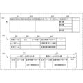
- FIG. 4 is a diagram showing the configuration of the database 304 and calibration table 312 according to this embodiment. Note that in FIG. 4, the same reference numerals are given to the same components as in FIGS. 2A and 3.
- the layered manufacturing data 231 in the database 304 is two-dimensional data obtained by slicing a layered object into layers.
- the additive manufacturing data 231 includes the additive manufacturing powder material 412 to be used, the additive manufacturing object parameters 413 such as the layer thickness for generating the additive manufacturing object, and the irradiation position of each layer sliced into layer units in association with the additive manufacturing object ID 411.
- Each layer irradiation data 414 indicating .
- the additive manufacturing control parameters 232 of the database 304 are parameters for controlling the operations of the laser beam irradiation unit 201, the electron beam irradiation unit 202, the additive manufacturing mechanism unit 204, and the additive manufacturing measurement unit 205. In this embodiment, parameters related to the laser beam irradiation section 201 and the electron beam irradiation section 202 are shown, and the others are omitted.
- the additive manufacturing control parameter 232 stores an output 422 of the irradiation beam, a beam diameter 423 on the additive manufacturing powder material, and a scan control parameter 424 in association with the irradiation beam 421 indicating whether it is a laser beam or an electron beam. .
- the scan control parameter 424 stores a scanning position based on mirror control in the case of a laser beam, and a scanning position based on deflection control in the case of an electron beam.
- the calibration table 312 is used by the calibration unit 311 during calibration before additive manufacturing. Note that in the calibration table 312 as well, similarly to the additive manufacturing control parameters 232, data related to the laser beam irradiation section 201 and the electron beam irradiation section 202 are shown, and the others are omitted.
- the calibration table 312 stores a laser beam test value 431, an electron beam test value 432, and a test result evaluation 433.
- the laser beam test value 431 includes the beam diameter of the laser beam and scan control parameters such as mirror control values.
- the electron beam test value 432 includes the beam diameter of the electron beam and scan control parameters such as a deflection control value.
- the calibration unit 311 refers to the test result evaluation 433 and calculates the additive manufacturing data 231 from the additive manufacturing test, the additive manufacturing control parameters, and the additive manufacturing results based on the laser beam test value 431 and the electron beam test value 432. Evaluate whether they match, and if they do not match, repeat calibration until they match within a predetermined error.
- FIG. 5 is a flowchart showing the processing procedure of the control unit 203 of the layered manufacturing apparatus 200 according to the present embodiment. Note that FIG. 5 also illustrates the process of generating additive manufacturing data in the information processing device 210. The processing of the control unit 203 in this flowchart is executed by the CPU in the control unit 203 using the RAM.
- step S511 the information processing device 210 executes a shape data preparation process for the layered object.
- step S513 the information processing device 210 executes an electron beam route setting process for each layer.
- Steps S511 and S513 correspond to generation of 2D-slice data from 3D-CAD data in the information processing device 210 in FIG. 3.
- step S521 the control unit 203 optionally performs a beam calibration step for motivating the laser beam scanning and the electron beam scanning, if necessary.
- the beam calibration step the irradiation beam diameter of the laser beam, the irradiation beam diameter of the electron beam, the scanning position of the laser beam, and the scanning position of the electron beam are calibrated before additive manufacturing.
- the calibration is repeated until an appropriate irradiation beam diameter and scanning position are obtained.
- the beam calibration step may be omitted if the additive manufacturing apparatus 200 is specialized to manufacture a specific additive manufacturing object using a specific additive manufacturing powder material, but if the additive manufacturing powder material is changed or , a beam calibration step is required when the target layered object is changed.
- the configuration may be such that the history up to now is accumulated and the appropriate irradiation beam diameter and scanning position are estimated from the learning results.
- step S523 the control unit 203 sets a variable n indicating the n-th layer to the first layer.
- step S525 the control unit 203 executes an n-th layer powder bed forming process.
- the powder bed changes depending on the melting point of the metal in order to remove residual stress from the model, but for example, if the melting point is around 1500°C, the base plate is heated to 500°C to 600°C in advance. A powder bed is formed on top of it.
- the control unit 203 synchronizes the laser beam irradiation process for "conductive state (physical bonding)" of the powder bed in step S527 and the modeling electron beam irradiation process in step S529, and executes them for each layer.
- the irradiation beam diameter of the laser beam and the scanning position on the layered manufacturing powder material are controlled.
- the irradiation beam diameter of the electron beam and the scanning position on the layered building powder material are controlled.
- the control unit 203 adds 1 to the variable n in step S531.
- the control unit 203 determines whether the variable n is the last Nth layer of the layered object. If it is the last Nth layer, the layered manufacturing is finished, and if it is not the last Nth layer, the process returns to step S525 and the next layer is repeated.
- effective additive manufacturing can be performed by combining a laser beam and an electron beam. That is, by considering the characteristics of the laser beam and the characteristics of the electron beam, it is possible to perform additive manufacturing that does not generate smoke or pores. Furthermore, by compensating the scanning of the laser beam and electron beam, it is possible to manufacture a high quality layered product.
- additive manufacturing using the existing PBF-EB method generates smoke, which limits the metal powders that can be used.
- the preheating temperature should be set to avoid smoke, and find the lower limit of the preheating temperature that can avoid smoke. It required a lot of effort.
- "physical bonding" in the powder bed is made possible by laser beam irradiation, so there is no need to consider the lower limit temperature setting of the preheating temperature to avoid smoke for each powder in the powder bed.
- the additive manufacturing process can be performed by preheating the base plate to a temperature that can remove the residual stress of the model (e.g., about 600°C for powder with a melting point of about 1500°C), forming a powder bed, and then performing the additive manufacturing process. . Furthermore, if residual stress countermeasures are not required, an additive manufacturing process that does not require preheating, similar to existing laser beam processes, becomes possible.
- the preheating process using electron beam irradiation to avoid smoke currently takes up 60% to 80% of the molding time.
- the preheating process by electron beam irradiation which was previously necessary, becomes unnecessary, making it possible to shorten the molding time.
- scanning with a high-speed electron beam we can expect the possibility of developing a printing technology that can ultra-fasten existing printing speeds (10 to 100 times faster than existing technologies).
- the additive manufacturing method and additive manufacturing apparatus according to the present embodiment are different from the second embodiment in that they are applicable even when using a new additive manufacturing powder material.
- the granulated powder is prepared based on the step of preparing a granulated powder of a metal alloy or a granulated powder of a metal and ceramics, and and selecting an appropriate laser beam wavelength and irradiation energy.
- the granulated powder of metal and ceramics is made by coating metal powder with ceramic powder like a dumpling.
- FIG. 7 is a block diagram showing the functional configuration of the control unit 703 of the layered manufacturing apparatus according to this embodiment.
- the same reference numerals are attached to the same components as in FIG. 3, and redundant explanation will be omitted.
- the control unit 703 further includes an additive manufacturing powder material characteristic receiving unit 710 and a target material adjusting unit 711.
- the additive manufacturing powder material characteristic receiving unit 710 receives the characteristics of the additive manufacturing powder material used in the additive manufacturing apparatus of this embodiment from the information processing device 210.
- the additive manufacturing powder materials used include not only known materials but also new materials.
- the additive manufacturing powder material includes metal-based materials (such as metal alloys) and granulated materials of metal-based materials and ceramic materials.
- the target material adjustment unit 711 has a target material table 712, and finds additive manufacturing control parameters for the laser beam and electron beam suitable for the additive manufacturing apparatus to perform additive manufacturing using the received additive manufacturing powder material. A request is made to the calibration section 311.
- FIG. 8 is a diagram showing the configuration of the target material table 712 according to this embodiment.
- the target material table 712 provides parameters when the target material adjustment unit 711 requests the calibration unit 311 to find appropriate additive manufacturing control parameters for the laser beam and electron beam.
- the target material table 712 stores material composition (weight %) 812 and material properties 813 such as particle size in association with the additive manufacturing powder material ID 811 used in the additive manufacturing apparatus. Further, the target material table 712 stores a laser beam setting value 814 and an electron beam setting value 815, which are calibration targets of the calibration unit 311, and a test result evaluation 816 by the calibration unit 311.
- the material composition 812 includes existing metal-based materials, granulated materials of metal-based and ceramic-based materials, or new metal-based materials or granulated materials of metal-based and ceramic-based materials.
- the laser beam setting value 814 and the electron beam setting value 815 include an adjustment output of the adjustment target, an adjustment beam diameter of the adjustment target, and scan control data of the adjustment target.
- the laser beam setting value 814 and the electron beam setting value 815 are set to the laser beam test value 431 and the electron beam test value 432 of the calibration table 312, and it is checked whether they are appropriate. If not appropriate, the laser beam setting value 814 and the electron beam setting value 815 are changed and repeated until they are appropriate within a predetermined error. In this way, it becomes possible to perform additive manufacturing on new additive manufacturing powder materials using an electron beam that can avoid smoke, and the results of additive manufacturing can be verified.
- FIG. 9 is a flowchart showing the processing procedure of the control unit 703 of the layered manufacturing apparatus according to this embodiment. Note that in FIG. 9, steps similar to those in FIG. 5 are given the same step numbers, and redundant explanations will be omitted. The processing of the control unit 703 in this flowchart is executed by the CPU in the control unit 703 using the RAM.
- step S910 an existing or new material powder manufacturing process is executed by a material powder manufacturing apparatus (not shown). Furthermore, in step S930, the control unit 703 uses the target material table 712 to execute a beam adjustment process according to the target material. In this beam adjustment, as described above in the description of the target material table 712, the beam adjustment is repeated until an appropriate beam diameter and scanning position are obtained.
- the beam adjustment process and the beam calibration process may be omitted if the additive manufacturing apparatus is specialized to manufacture a specific additive manufacturing object using a specific additive manufacturing powder material. If a new material is used or if the target layered object is new, a beam adjustment step and a beam calibration step are required. Alternatively, the configuration may be such that the history up to now is accumulated and the appropriate beam diameter and scanning position are estimated from the learning results.
- effective additive manufacturing can be performed by combining a laser beam and an electron beam. That is, by considering the characteristics of the laser beam and the characteristics of the electron beam, it is possible to perform additive manufacturing that does not generate smoke or pores. Furthermore, as a result of eliminating defects caused by electron beams and laser beams, in addition to manufacturing higher quality additively manufactured objects using existing additive manufacturing powders, we are also able to develop new additive manufacturing powders and additively manufactured objects using them. A ripple effect can be expected. In other words, the physical binding of the powder bed by laser beam irradiation and the avoidance of smoke thereby eliminates the limitations of additive manufacturing using electron beams, making it possible to understand the basic science of metal additive manufacturing, develop new alloys, and improve the metal additive manufacturing process. It becomes possible to establish simulation technology.
- an additive manufacturing apparatus that has a hybrid heat source of laser beam and electron beam, and metal/ceramic granulated powder, which is the basis of material design, is created through an ultra-instantaneous extreme environment.
- the additive manufacturing apparatus of this embodiment it is possible to develop new composite materials such as high-strength metal materials that cannot be realized with existing processes, and it is possible to develop new composite materials using new material science techniques. You can expect it.
- This is a new material development tool that cannot be obtained through the conventional material development process bound by the rules of the natural world (thermodynamics).
- this embodiment avoids the disadvantages of laser additive manufacturing technology (keyhole formation in the melt pool, spatter generation, etc.) and the advantages of electron beam additive manufacturing technology (thermal conductive deep penetration melt pool). It is possible to provide a metal additive manufacturing technology that can make maximum use of metal additive manufacturing, and to dramatically expand and popularize the use of metal additive manufacturing. By realizing the additive manufacturing technology of this embodiment, it is not only possible to manufacture metal parts as desired, but also the degree of freedom when designing metal parts (steel type, structure, shape, composite, etc.) is increased. Therefore, it is expected that more highly functional metal parts will be produced.
- the melting solidification phenomenon (ultra-rapid melting/ultra-rapid solidification phenomenon) that only appears in the powder bed fusion bonding metal additive manufacturing (hereinafter referred to as PBF-EBM) process can be applied to new materials. It can be used to the fullest for development.
- PBF-EBM powder bed fusion bonding metal additive manufacturing
- the present inventor has previously studied the metallurgical phenomena that occur characteristically in the PBF-EBM process - super-heating melting, super-rapid cooling solidification, and super-convection flow when subjected to extremely high energy in an extremely short time.
- MC composite materials such as Al/Al 2 O 3 , Al/AlN, Al/SiC, Cu/Al 2 O 3 , Ti/TiC, Fe/TiB 2 , strength (hardness) and thermal conductivity/thermal It is possible to develop a new alloy whose expansion rate can be controlled arbitrarily. It is possible to form granulated powder of low melting point (or/&) high melting point metal/high strength ceramics. Continuous control of electrical/thermal conductivity, rigidity, and coefficient of thermal expansion between physical properties of Al, Cu, Ti alloy, steel, Al 2 O 3 , AlN, SiC, TiC, and TiB 2 becomes possible.
- the Inconel 713C/SiC MC composite material we have developed a low coefficient of thermal expansion based on a super heat-resistant Ni-based superalloy to increase thermal shock resistance and improve wear resistance. and can improve hardness.
- the present invention may be applied to a system composed of a plurality of devices, or may be applied to a single device. Furthermore, the present invention is also applicable to a case where an information processing program that implements the functions of the embodiments is supplied to a system or device and executed by a built-in processor.
- a program installed on a computer a medium storing the program, a server for downloading the program, and a processor executing the program are also included in the technical scope of the present invention.
- a non-transitory computer readable medium storing at least a program that causes a computer to execute the processing steps included in the embodiments described above is within the technical scope of the present invention.
Landscapes
- Engineering & Computer Science (AREA)
- Chemical & Material Sciences (AREA)
- Materials Engineering (AREA)
- Manufacturing & Machinery (AREA)
- Health & Medical Sciences (AREA)
- General Health & Medical Sciences (AREA)
- Toxicology (AREA)
- Automation & Control Theory (AREA)
- Physics & Mathematics (AREA)
- Plasma & Fusion (AREA)
- Powder Metallurgy (AREA)
Priority Applications (2)
| Application Number | Priority Date | Filing Date | Title |
|---|---|---|---|
| JP2024536749A JPWO2024024109A1 (https=) | 2022-07-29 | 2022-07-29 | |
| PCT/JP2022/029362 WO2024024109A1 (ja) | 2022-07-29 | 2022-07-29 | 積層造形装置および積層造形方法 |
Applications Claiming Priority (1)
| Application Number | Priority Date | Filing Date | Title |
|---|---|---|---|
| PCT/JP2022/029362 WO2024024109A1 (ja) | 2022-07-29 | 2022-07-29 | 積層造形装置および積層造形方法 |
Publications (1)
| Publication Number | Publication Date |
|---|---|
| WO2024024109A1 true WO2024024109A1 (ja) | 2024-02-01 |
Family
ID=89705864
Family Applications (1)
| Application Number | Title | Priority Date | Filing Date |
|---|---|---|---|
| PCT/JP2022/029362 Ceased WO2024024109A1 (ja) | 2022-07-29 | 2022-07-29 | 積層造形装置および積層造形方法 |
Country Status (2)
| Country | Link |
|---|---|
| JP (1) | JPWO2024024109A1 (https=) |
| WO (1) | WO2024024109A1 (https=) |
Citations (6)
| Publication number | Priority date | Publication date | Assignee | Title |
|---|---|---|---|---|
| WO2015194678A1 (ja) * | 2014-06-20 | 2015-12-23 | 株式会社フジミインコーポレーテッド | 粉末積層造形に用いる粉末材料およびそれを用いた粉末積層造形法 |
| US20170334023A1 (en) * | 2014-11-04 | 2017-11-23 | Dresser-Rand Company | System and method for additive manufacturing of turbomachine components |
| US20180079003A1 (en) * | 2015-03-10 | 2018-03-22 | Tsinghua University | Additive manufacturing device utilizing eb-laser composite scan |
| WO2020059183A1 (ja) * | 2018-09-19 | 2020-03-26 | 技術研究組合次世代3D積層造形技術総合開発機構 | 金属積層造形用粉末およびその製造方法と、積層造形装置およびその制御プログラム |
| US20210032165A1 (en) * | 2019-07-30 | 2021-02-04 | Chongqing Institute Of East China Normal University | Method for preparing carbon-reinforced metal-ceramic composite material |
| KR102388622B1 (ko) * | 2021-02-26 | 2022-04-19 | 창원대학교 산학협력단 | 미세조직 개선 및 인장강도 향상을 위한 초내열합금 in718의 3d 프린팅 제조방법 및 그에 의해 제조되는 초내열합금 in718 합금 |
Family Cites Families (2)
| Publication number | Priority date | Publication date | Assignee | Title |
|---|---|---|---|---|
| JP6600278B2 (ja) * | 2016-06-07 | 2019-10-30 | 三菱重工業株式会社 | 選択型ビーム積層造形装置及び選択型ビーム積層造形方法 |
| JP2019090072A (ja) * | 2017-11-13 | 2019-06-13 | 株式会社ジェイテクト | 積層造形物の製造装置及び製造方法 |
-
2022
- 2022-07-29 WO PCT/JP2022/029362 patent/WO2024024109A1/ja not_active Ceased
- 2022-07-29 JP JP2024536749A patent/JPWO2024024109A1/ja active Pending
Patent Citations (6)
| Publication number | Priority date | Publication date | Assignee | Title |
|---|---|---|---|---|
| WO2015194678A1 (ja) * | 2014-06-20 | 2015-12-23 | 株式会社フジミインコーポレーテッド | 粉末積層造形に用いる粉末材料およびそれを用いた粉末積層造形法 |
| US20170334023A1 (en) * | 2014-11-04 | 2017-11-23 | Dresser-Rand Company | System and method for additive manufacturing of turbomachine components |
| US20180079003A1 (en) * | 2015-03-10 | 2018-03-22 | Tsinghua University | Additive manufacturing device utilizing eb-laser composite scan |
| WO2020059183A1 (ja) * | 2018-09-19 | 2020-03-26 | 技術研究組合次世代3D積層造形技術総合開発機構 | 金属積層造形用粉末およびその製造方法と、積層造形装置およびその制御プログラム |
| US20210032165A1 (en) * | 2019-07-30 | 2021-02-04 | Chongqing Institute Of East China Normal University | Method for preparing carbon-reinforced metal-ceramic composite material |
| KR102388622B1 (ko) * | 2021-02-26 | 2022-04-19 | 창원대학교 산학협력단 | 미세조직 개선 및 인장강도 향상을 위한 초내열합금 in718의 3d 프린팅 제조방법 및 그에 의해 제조되는 초내열합금 in718 합금 |
Also Published As
| Publication number | Publication date |
|---|---|
| JPWO2024024109A1 (https=) | 2024-02-01 |
Similar Documents
| Publication | Publication Date | Title |
|---|---|---|
| Mumtaz et al. | High density selective laser melting of Waspaloy® | |
| US11260475B2 (en) | Method and system for powder bed fusion additive manufacturing of crack-free aluminum alloys | |
| JP6728389B2 (ja) | 傾斜中間層を有するスパッタリングターゲットアセンブリ及び作製方法 | |
| US10232602B2 (en) | Method and apparatus for producing three-dimensional objects with improved properties | |
| EP2961549B1 (en) | Apparatus and method for producing work pieces having a tailored microstructure | |
| Li et al. | Effect of substrate temperature on the interface bond between support and substrate during selective laser melting of Al–Ni–Y–Co–La metallic glass | |
| JP6717573B2 (ja) | 繊維強化を用いた付加製造方法 | |
| EP2796229B1 (en) | Methods for forming dispersion-strengthened aluminum alloys | |
| Khmyrov et al. | Synthesis of nanostructured WC-Co hardmetal by selective laser melting | |
| US20140349132A1 (en) | Method for manufacturing a compact component, and component that can be produced by means of the method | |
| US20160368077A1 (en) | Surface processing in additive manufacturing with laser and gas flow | |
| US20190366480A1 (en) | Additive manufacturing with metal wire | |
| CA3042143C (en) | Method, use and apparatus for producing a single-crystalline work piece | |
| WO2017120279A1 (en) | Materials and formulations for three-dimensional printing | |
| CN113631303A (zh) | 增材制造 | |
| Abdulrahman et al. | Laser metal deposition of titanium aluminide composites: A review | |
| CN115570783A (zh) | 脉冲激光选区熔化一体化成型系统及方法 | |
| WO2020245633A1 (en) | Additive manufacturing system with metal wire | |
| WO2024024109A1 (ja) | 積層造形装置および積層造形方法 | |
| Wolff | Directed energy deposition | |
| WO2022078630A1 (en) | Method of manufacturing a build plate for use in an additive manufacturing process | |
| JP2019111684A (ja) | 造形物の製造方法 | |
| CN111687414A (zh) | 多束流电子束成型方法 | |
| Pfleging et al. | Laser additive manufacturing for the realization of new material concepts | |
| US10577684B1 (en) | Method for producing ultrafine-grained crystalline materials via electron beam processing |
Legal Events
| Date | Code | Title | Description |
|---|---|---|---|
| 121 | Ep: the epo has been informed by wipo that ep was designated in this application |
Ref document number: 22953197 Country of ref document: EP Kind code of ref document: A1 |
|
| ENP | Entry into the national phase |
Ref document number: 2024536749 Country of ref document: JP Kind code of ref document: A |
|
| NENP | Non-entry into the national phase |
Ref country code: DE |
|
| 122 | Ep: pct application non-entry in european phase |
Ref document number: 22953197 Country of ref document: EP Kind code of ref document: A1 |