WO2024024019A1 - 仮想空間における情報処理装置の使用のための制御 - Google Patents
仮想空間における情報処理装置の使用のための制御 Download PDFInfo
- Publication number
- WO2024024019A1 WO2024024019A1 PCT/JP2022/029100 JP2022029100W WO2024024019A1 WO 2024024019 A1 WO2024024019 A1 WO 2024024019A1 JP 2022029100 W JP2022029100 W JP 2022029100W WO 2024024019 A1 WO2024024019 A1 WO 2024024019A1
- Authority
- WO
- WIPO (PCT)
- Prior art keywords
- communication device
- virtual
- virtual machine
- virtual space
- user
- Prior art date
- Legal status (The legal status is an assumption and is not a legal conclusion. Google has not performed a legal analysis and makes no representation as to the accuracy of the status listed.)
- Ceased
Links
Images




Classifications
-
- G—PHYSICS
- G06—COMPUTING OR CALCULATING; COUNTING
- G06T—IMAGE DATA PROCESSING OR GENERATION, IN GENERAL
- G06T19/00—Manipulating three-dimensional [3D] models or images for computer graphics
-
- G—PHYSICS
- G06—COMPUTING OR CALCULATING; COUNTING
- G06F—ELECTRIC DIGITAL DATA PROCESSING
- G06F9/00—Arrangements for program control, e.g. control units
- G06F9/06—Arrangements for program control, e.g. control units using stored programs, i.e. using an internal store of processing equipment to receive or retain programs
- G06F9/44—Arrangements for executing specific programs
- G06F9/455—Emulation; Interpretation; Software simulation, e.g. virtualisation or emulation of application or operating system execution engines
- G06F9/45533—Hypervisors; Virtual machine monitors
- G06F9/45558—Hypervisor-specific management and integration aspects
-
- G—PHYSICS
- G06—COMPUTING OR CALCULATING; COUNTING
- G06F—ELECTRIC DIGITAL DATA PROCESSING
- G06F3/00—Input arrangements for transferring data to be processed into a form capable of being handled by the computer; Output arrangements for transferring data from processing unit to output unit, e.g. interface arrangements
- G06F3/01—Input arrangements or combined input and output arrangements for interaction between user and computer
- G06F3/048—Interaction techniques based on graphical user interfaces [GUI]
- G06F3/0481—Interaction techniques based on graphical user interfaces [GUI] based on specific properties of the displayed interaction object or a metaphor-based environment, e.g. interaction with desktop elements like windows or icons, or assisted by a cursor's changing behaviour or appearance
- G06F3/04815—Interaction with a metaphor-based environment or interaction object displayed as three-dimensional [3D], e.g. changing the user viewpoint with respect to the environment or object
-
- G—PHYSICS
- G06—COMPUTING OR CALCULATING; COUNTING
- G06F—ELECTRIC DIGITAL DATA PROCESSING
- G06F3/00—Input arrangements for transferring data to be processed into a form capable of being handled by the computer; Output arrangements for transferring data from processing unit to output unit, e.g. interface arrangements
- G06F3/01—Input arrangements or combined input and output arrangements for interaction between user and computer
- G06F3/048—Interaction techniques based on graphical user interfaces [GUI]
- G06F3/0484—Interaction techniques based on graphical user interfaces [GUI] for the control of specific functions or operations, e.g. selecting or manipulating an object, an image or a displayed text element, setting a parameter value or selecting a range
- G06F3/04842—Selection of displayed objects or displayed text elements
-
- G—PHYSICS
- G06—COMPUTING OR CALCULATING; COUNTING
- G06F—ELECTRIC DIGITAL DATA PROCESSING
- G06F9/00—Arrangements for program control, e.g. control units
- G06F9/06—Arrangements for program control, e.g. control units using stored programs, i.e. using an internal store of processing equipment to receive or retain programs
- G06F9/44—Arrangements for executing specific programs
- G06F9/455—Emulation; Interpretation; Software simulation, e.g. virtualisation or emulation of application or operating system execution engines
- G06F9/45533—Hypervisors; Virtual machine monitors
- G06F9/45558—Hypervisor-specific management and integration aspects
- G06F2009/45579—I/O management, e.g. providing access to device drivers or storage
-
- G—PHYSICS
- G06—COMPUTING OR CALCULATING; COUNTING
- G06F—ELECTRIC DIGITAL DATA PROCESSING
- G06F3/00—Input arrangements for transferring data to be processed into a form capable of being handled by the computer; Output arrangements for transferring data from processing unit to output unit, e.g. interface arrangements
- G06F3/01—Input arrangements or combined input and output arrangements for interaction between user and computer
- G06F3/011—Arrangements for interaction with the human body, e.g. for user immersion in virtual reality
- G06F3/012—Head tracking input arrangements
-
- G—PHYSICS
- G06—COMPUTING OR CALCULATING; COUNTING
- G06T—IMAGE DATA PROCESSING OR GENERATION, IN GENERAL
- G06T2200/00—Indexing scheme for image data processing or generation, in general
- G06T2200/24—Indexing scheme for image data processing or generation, in general involving graphical user interfaces [GUIs]
Definitions
- the present disclosure relates to a technology for using an information processing device provided in a virtual store represented in a virtual space.
- Patent Document 1 in response to a user performing a selection operation of a predetermined product in a virtual store displayed on a first terminal device, details of the predetermined product are displayed on a second terminal device. A technique for displaying is disclosed. Furthermore, Patent Document 2 discloses a technology for changing (customizing) the specifications of a product selected by a user in a virtual store and paying for the product after the specifications have been changed.
- JP2021-131661A Japanese Patent Application Publication No. 2022-36691
- a virtual store like the one described in the above document, it is possible to sell products in real space. This allows the user to purchase products in the real space while being in the virtual space.
- the user may want to check the usability of the product.
- a virtual store that sells communication devices that can be used in real space a user may want to check the usability and operational convenience of the communication devices.
- no mechanism has been provided in virtual space for using communication devices that can be used in real space in virtual space.
- the present disclosure aims to provide a mechanism for using an information processing device that can be used in real space in virtual space.
- a virtual space system includes one or more processors, and at least one of the one or more processors performs a first detection process and a first display process. , a second detection process, an acquisition process, and a second display process are executed.
- the first detection process is a process of detecting a communication device object selected from a plurality of communication device objects in the virtual space.
- the first display process is a process of displaying a display screen of the same communication device as the model represented by the selected communication device object, which is realized by a virtual machine, in a predetermined display area.
- the second detection process is a process of detecting an operation on the display screen in the display area.
- the acquisition process is a process of inputting information indicating the operation into the virtual machine to acquire a display screen of the communication device realized by the virtual machine that is displayed according to the operation.
- the second display process is a process of displaying the display screen displayed according to the operation in the display area.
- a virtual space control method includes a first detection step, a first display step, a second detection step, an acquisition step, and a second display step.
- a communication device object selected from a plurality of communication device objects in the virtual space is detected.
- a display screen of the same communication device as the model represented by the selected communication device object, which is realized by a virtual machine is displayed in a predetermined display area.
- an operation on the display screen in the display area is detected.
- the acquisition step a display screen displayed according to the operation of the communication device realized by the virtual machine is acquired by inputting information indicating the operation into the virtual machine.
- the display screen displayed according to the operation is displayed in the display area.
- a user can use an information processing device that can be used in a real space in a virtual space.
- FIG. 1 shows a configuration example of a virtual space system according to an embodiment of the present disclosure.
- FIG. 2 shows a configuration example of a head mounted display (HMD) according to an embodiment of the present disclosure.
- FIG. 3 shows a configuration example of a VR content distribution device according to an embodiment of the present disclosure.
- FIG. 4 shows a configuration example of a screen generation device according to an embodiment of the present disclosure.
- FIG. 5 shows an example of a communication sequence diagram of the HMD, the VR content distribution device, and the screen generation device.
- FIG. 6 shows another example of a communication sequence diagram of the HMD, the VR content distribution device, and the screen generation device.
- FIG. 7A shows an example of a VR image displayed on the HMD.
- FIG. 7B shows an example of a VR image for selecting a user terminal to be used in the virtual space.
- FIG. 7C shows an example of a VR image for selecting a terminal usage mode.
- FIG. 7D shows an example of a VR image in which an avatar-dedicated user terminal operated by a user is displayed.
- FIG. 7E shows an example of a VR image including a display screen with screen data embedded therein.
- FIG. 7F shows an example of a VR image in which a user terminal dedicated to the user is displayed in a superimposed manner.
- FIG. 7G shows an example of a VR image including a display screen displaying screen data.
- VR virtual reality
- a real user human
- his/her alter ego called an avatar
- metaverse that is a mechanism thereof.
- the term virtual reality space shall mean a virtual space, such as a metaverse, in which a user can act as his/her own alter ego.
- FIG. 1 shows a configuration example of a virtual space system 1 according to this embodiment.
- the virtual space system 1 includes a head mounted display (HMD) 10, a VR content distribution device 20, and a screen data generation device 30.
- the HMD 10 is a device that can be mounted on the head of a user (player) 12.
- the HMD 10 outputs VR content constituting a virtual space distributed by the VR content distribution device 20, and the user 12 can view the VR content.
- the VR content includes at least a VR image (image data that constitutes a virtual space), and may also include metadata and audio indicating information about objects in the virtual space. Note that in this embodiment, the term "image” is understood to include still images and/or moving images.
- the user 12 can enjoy the virtual space by viewing VR content.
- a virtual reality (VR) system is configured by the VR content distribution device 20 and the screen data generation device 30.
- the HMD 10 may be a binocular type or a monocular type. Further, the HMD 10 may be of a transmissive type that completely covers the eyes of the user 12, or may be of a transmissive type. In the case of a transparent type, a more immersive feeling can be provided. Further, the HMD 10 may be a goggle-type, glasses-type, or hat-type device.
- the user 12 can perform various controls and settings such as controlling an avatar corresponding to the user 12. For example, the user 12 can perform a desired input operation by tilting the controller 11 or pressing a button (not shown) provided on the controller 11.
- the controller 11 is composed of one piece of hardware, it may be composed of two controllers, one for the right hand and one for the left hand. Further, the controller 11 is not limited to a form in which it is held by the user 12, but may be in any form as long as it allows input operations by the user 12.
- the VR content distribution device 20 is a device that constitutes a VR system, and specifically provides VR content (that is, virtual space) to the user 12 by distributing the VR content to the HMD 10.
- the VR content distribution device 20 includes a content database.
- the content database includes image data representing a virtual space (VR image), model data of an avatar that is the alter ego of the user 12, audio data, and the like.
- the VR content distribution device 20 uses data stored in the content database to generate a VR image according to the movement of the HMD 10 or the operation on the controller 11, and transmits (distributes) the VR image to the HMD 10.
- audio may be transmitted to the HMD 10 in response to the movement of the HMD 10 or the operation by the controller 11.
- the behavior of the avatar can be controlled by the user 12 operating the controller 11 . Note that the avatar's behavior may be controlled by the movement of the HMD 10.
- the virtual space system 1 allows the user 12 to use communication devices that can be used in the real space in a virtual store that is expressed (deployed) in the virtual space provided by the VR content distribution device 20. It is configured as follows. That is, the virtual space system 1 is configured so that the user 12 can simulate the usability of a communication device that can be used in the real space in the virtual space via the HMD 10.
- an example of the configuration of a virtual space system that implements such processing an example of the configuration of each device (system) that makes up the virtual space system, and an example of a specific processing procedure will be described.
- an object in the shape of a communication device is expressed in a virtual store.
- the object in the virtual space or virtual store will also simply be referred to as a communication device or a user terminal.
- the user 12 selects one communication device from a plurality of communication devices placed in a virtual space and uses the selected communication device virtually (simulated).
- the object that the user 12 uses virtually is a user terminal such as a smartphone, but it may be any other communication device or an information processing device that does not have a communication function. It's okay.
- an information processing device called a communication device that has a communication function may be used virtually, or an information processing device that does not have a communication function may be used virtually.
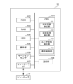
- FIG. 2 shows a configuration example of the HMD 10 (first information processing device) according to this embodiment.
- the HMD 10 includes a CPU 101, a ROM 102, a RAM 103, an HDD 104, a display section 105, a motion sensor 106, a controller I/F (interface) 107, and a communication section 108 as a hardware configuration.
- the HMD 10 may also include an external memory and a line of sight detection sensor (a sensor that detects movement of the user's 12 line of sight).
- the HMD 10 also includes a terminal selection detection section 111, a terminal operation detection section 112, a user state detection section 113, and a display control section 114 as functional configurations executed by the CPU 201.
- a CPU (Central Processing Unit) 101 is composed of one or more processors, and controls operations in the HMD 10 in an integrated manner.
- the CPU 101 includes an ASIC (Application Specific Integrated Circuit), an FPGA (Field Programmable Gate Array), and a DSP (Digital Signal Array). It may be replaced by one or more processors such as a GPU (Graphics Processing Unit) or a Graphics Processing Unit (GPU). The functional configuration of the CPU 101 will be described later.
- a ROM (Read Only Memory) 102 is a nonvolatile memory that stores control programs and the like necessary for the CPU 101 to execute processing. Note that the program may be stored in a nonvolatile memory such as an HDD (Hard Disk Drive) 104 or an SSD (Solid State Drive), or an external memory such as a removable storage medium (not shown).
- a RAM (Random Access Memory) 103 is a volatile memory and functions as the main memory, work area, etc. of the CPU 101. That is, the CPU 101 loads necessary programs and the like from the ROM 102 into the RAM 103 when executing processing, and implements various functional operations by executing the programs and the like.
- the HDD 104 stores, for example, various data and information necessary when the CPU 101 performs processing using a program. Further, the HDD 104 stores various data, various information, etc. obtained by the CPU 101 performing processing using programs and the like. Note that the storage may be performed using an external memory such as a nonvolatile memory such as an SSD or a removable storage medium together with or in place of the HDD 104.
- an external memory such as a nonvolatile memory such as an SSD or a removable storage medium together with or in place of the HDD 104.
- the display unit 105 is realized by a liquid crystal display or the like.
- the display unit 105 is provided with a first display (first display area) set in front of the left eye of the user 12 and a second display (second display area) set in front of the right eye of the user 12.
- first display first display area
- second display second display area
- the display control unit 114 of the CPU 101 generates a left-eye image and a right-eye image with different parallaxes, and displays the left-eye image on the first display.
- the right eye image can be displayed on the second display.
- the display unit 105 may be configured as an integrated display that combines a first display and a second display.
- the motion sensor 106 detects information indicating the posture of the user 12 wearing the HMD 10 (hereinafter referred to as posture information), such as the rotation angle and inclination of the HMD 10.
- posture information information indicating the posture of the user 12 wearing the HMD 10.
- the motion sensor 106 may be configured by combining a gyro sensor, an acceleration sensor, an angular acceleration sensor, or the like.
- the controller I/F 107 detects (receives) information (hereinafter referred to as operation information) indicating an operation performed by the user 12 on the controller 11 from the controller 11 .
- the controller I/F 107 receives operation information via the communication unit 108.
- the user's operations on the controller 11 include, for example, pressing a button provided on the controller 11, changing the position, orientation, and tilt of the controller 11, and/or the level of force with which the controller 11 is gripped.
- the HMD 10 is configured to receive operation information from the controller 11 and transmit it to the VR content distribution device 20.
- the controller 11 may be configured to directly transmit the operation information to the VR content distribution device 20.
- the communication unit 108 is an interface that controls communication between the HMD 10 and external devices.
- the communication unit 108 is configured to communicate with the VR content distribution device 20 and the screen data generation device 30 via a communication network such as the Internet and a wireless LAN.
- the terminal selection detection unit 111 detects information corresponding to terminal selection (terminal selection information) from among the posture information of the user 12 detected by the motion sensor 106 and the operation information of the user 12 detected by the controller I/F 107. do.
- Terminal selection is an operation in which the user 12 selects one user terminal from a plurality of user terminals (communication device objects) placed in a virtual store represented in the VR image (virtual space) displayed on the display unit 105. It is. Terminal selection corresponds to, for example, an operation by the controller 11 of selecting one user terminal from among a plurality of user terminals in the virtual space. Alternatively, predetermined movements and operations on the HMD 10 and controller 11 may be set in advance to correspond to terminal selection.
- the terminal selection information indicates, for example, the position of a selection operation in a VR image or a virtual store. Alternatively, the terminal selection information may be information (identification information) that identifies one user terminal selected from among a plurality of user terminals.
- the terminal selection information includes information on the usage mode (terminal usage mode) of the user terminal selected by the user 12 in the virtual space.
- the terminal usage mode will be described later.
- the terminal selection information is transmitted to the VR content distribution device 20 via the communication unit 108 or from the controller 11.
- the terminal operation detection unit 112 detects information corresponding to the terminal operation (terminal operation information) from the posture information of the user 12 detected by the motion sensor 106 and the operation information of the user 12 detected by the controller I/F 107. do.
- the terminal operation is an operation on the user terminal selected by the user 12.
- the terminal operation corresponds to an operation performed on a predetermined area (also referred to as an operation area) by the controller 11.
- the operation area may be determined in advance, or may be determined by operation via the controller 11 or the like.
- the area where images are displayed and the area where operations are performed may not match, such as on a laptop, or the area where images are displayed and the area where operations are performed, such as on a smartphone's touch panel. Sometimes the areas match. Therefore, the display area described later and the operation area described above may or may not match. Furthermore, even when the display area and the operation area match, at least a portion of them may match.
- predetermined movements and operations on the HMD 10 and controller 11 may be set in advance to correspond to terminal operations.
- the terminal operation information may include position information and three-dimensional angle information at which the terminal operation was performed. Note that, as will be described later, the terminal operation is different depending on whether the user 12 uses the user terminal within the virtual space or when the user 12 uses the user terminal displayed superimposed on the virtual space.
- the user state detection unit 113 detects information that does not correspond to the terminal selection and terminal operation described above from among the posture information of the user 12 detected by the motion sensor 106 and the operation information of the user 12 detected by the controller I/F 107. Generated as user status information.
- the user status detection unit 113 can transmit user status information to the VR content distribution device 20 via the communication unit 108. User status information may also be sent from the controller 11.
- the user state information may include information on the movement of the user's 12 line of sight.
- the user status information also includes information indicating an operation to end use of the user terminal in the virtual store, which was used by the user 12.
- the display control unit 114 performs display control on the display unit 105.
- the display control unit 114 performs control to display a VR image generated by the VR content distribution device 20 on the display unit 105 in response to the user status information generated by the user status detection unit 113.
- the display control unit 114 can perform the control for stereoscopic display as described above.
- the display control unit 114 can superimpose and display an image for viewing the display screen of the user terminal selected by the user 12 on the VR image.
- the image may be an image simulating the user terminal selected by the user 12.
- the image may include a frame of the user terminal and a display screen inside the frame.
- the display control unit 114 can acquire the screen data generated by the screen data generation device 30 via the VR content distribution device 20 and display it on the display screen within the image.
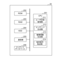
- FIG. 3 shows a configuration example of the VR content distribution device 20 (second information processing device) according to this embodiment.
- the VR content distribution device 20 distributes VR content to the HMD 10. If a predetermined login process (including an authentication process for logging in with a non-general-purpose account) by the user 12 is required in order to use VR content provided by the VR content distribution device 20, the user 12, for example, uses the HMD 10 or By operating the controller 11, a login process is performed using predetermined information (for example, ID and password). The login process may be performed by the VR content distribution device 20.
- a predetermined login process including an authentication process for logging in with a non-general-purpose account
- the VR content distribution device 20 includes a CPU 201, a ROM 202, a RAM 203, an HDD 204, a communication unit 205, and a content database 206 as a hardware configuration. Further, the VR content distribution device 20 includes a user status management section 211, a content generation section 212, a model information generation section 213, and a terminal operation transfer section 214 as functional components executed by the CPU 201.
- the basic configurations of the CPU 201, ROM 202, RAM 203, and HDD 204 are the same as those of the CPU 101, ROM 102, RAM 103, and HDD 104 in FIG. 2, so a description thereof will be omitted.
- the communication unit 205 is an interface that controls communication between the VR content distribution device 20 and external devices.
- the communication unit 205 is configured to communicate with the HMD 10 and the screen data generation device 30 via a communication network such as the Internet and a wireless LAN.
- the communication unit 205 may be configured to communicate with the controller 11.
- the content database 206 is configured to store image data (VR images) constituting the virtual space, model data of an avatar that is the alter ego of the user 12, audio data, etc. Further, in this embodiment, content database 206 is configured to store information regarding multiple user terminals at the virtual store. Specifically, each of the plurality of user terminals in the virtual store corresponds to a user terminal that can be used in real space, and the content database 206 stores information regarding the model (model information) for each user terminal in the virtual store. be done.
- the model information includes a manufacturer name, model number, etc., and can be stored in association with information (identification information) for identifying each user terminal. Alternatively, the model information may be stored in association with the position of each user terminal placed in the virtual store (position in the virtual space or virtual store). Further, the model information is stored in association with the shape data of the user terminal (an image including the frame and display screen of the user terminal) of the model information.
- the content database 206 and the VR content distribution device 20 may be separate devices. In that case, the VR content distribution device 20 can utilize data stored in the content database 206 by communicating with the content database 206.
- the user status management unit 211 detects (receives) the user status information transmitted by the user status detection unit 113 of the HMD 10 via the communication unit 205 and outputs it to the content generation unit 212. Note that when the user status information is information indicating an operation to terminate use of the user terminal in the virtual store, the user status management unit 211 transmits a termination instruction to the screen data generation device 30 via the communication unit 205.
- the content generation unit 212 generates VR content representing a virtual space from the data acquired from the content database 206 based on the user status information detected by the user status management unit 211.
- the VR content includes a VR image to be displayed on the HMD 10, and may also include audio.
- the content generation unit 212 distributes (transmits) the generated VR content to the HMD 20 via the communication unit 205.
- the content generation unit 212 generates VR content representing a virtual store where a plurality of user terminals are placed.
- each of the plurality of user terminals may have identification information.
- the content generation unit 212 can perform control to incorporate the screen data received from the screen data generation device 30 via the communication unit 205 into the VR image.
- the content generation unit 212 is configured to be able to incorporate (insert) the received screen data into a display area such as a display screen of a user terminal in the virtual space. Note that the received screen data may be transferred to the HMD 10 without being incorporated into the display area.
- the model information generation unit 213 detects (receives) the terminal selection information transmitted by the terminal selection detection unit 111 (or controller 11) of the HMD 10 via the communication unit 205, and identifies the user terminal according to the terminal selection information. do. Subsequently, the model information generation unit 213 obtains model information (manufacturer name and model number) of the specified user terminal (that is, selected by the user 12) from the content database 206. For example, if the terminal selection information is the location of the selection operation in the virtual store (or VR image), the model information generation unit 213 acquires the model information stored in the content database 206 in association with the location.
- the model information generation unit 213 obtains model information stored in the content database 206 in association with the model information.
- the model information generation unit 213 transmits the model information to the screen data generation device 30 via the communication unit 205.
- the transmitted model information means a request by the user 12 to use a user terminal having the model information (or to allocate a virtual machine having the model information).
- the model information generation unit 213 can output the model information to the content generation unit 212.
- the model information generation unit 213 can acquire shape data of the user terminal that is stored in the content database 206 in association with the model information.
- the terminal operation transfer unit 214 receives terminal operation information transmitted by the terminal operation detection unit 112 (or controller 11) of the HMD 10 via the communication unit 205, and transfers it to the screen data generation device 30. configured.
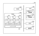
- FIG. 4 shows a configuration example of the screen data generation device 30 (third information processing device) according to this embodiment.
- the screen data generation device 30 includes a CPU 301, a ROM 302, a RAM 303, an HDD 304, and a communication unit 305 as a hardware configuration. Further, the screen data generation device 30 includes a virtual machine (VM) management section 311 and a screen data acquisition section 312 as functional components executed by the CPU 301.
- VM virtual machine
- the basic configurations of the CPU 301, ROM 302, and HDD 304 are the same as those of the CPU 101, ROM 102, and HDD 104 in FIG. 2, so a description thereof will be omitted.
- a hypervisor 321 and virtual machines (VM) 331, 332, and 333 are stored in the RAM 303.
- the virtual machine 331 includes a guest OS 341 and an application 351.
- the virtual machine 332 includes a guest OS 342 and an application 352.
- the virtual machine 333 includes a guest OS 343 and an application 353.
- the hypervisor 321 is a program for constructing a virtual environment, and in the example of FIG. 4 runs a plurality of virtual machines 331, 332, and 333 constructed on the hypervisor 321.
- a guest OS is basic software for running various applications in a virtual machine.
- the guest OS 341 operates an application 351, the guest OS 342 operates an application 352, and the guest OS 343 operates an application 353.
- the application 351 runs on the guest OS 341, the application 352 runs on the guest OS 342, and the application 353 is a program that runs on the guest OS 343.
- FIG. 3 shows an example in which the RAM 303 includes three virtual machines 331, 332, and 333, the number of virtual machines is not limited to a specific number.
- the virtual machine management unit 311 can manage virtual machines, such as creating and deleting virtual machines.
- the application in each virtual machine is a program for virtually realizing a user terminal (specifically, at least some functions of the terminal) that can be used in real space.
- the application is configured to receive terminal operation information as input and output (generate) screen data that is displayed on the display screen of the user terminal (transitions according to the terminal operation) according to the terminal operation corresponding to the information.
- each virtual machine functions as a virtual user terminal that can generate screen data to be displayed according to the user's 12 operations.
- Each virtual machine (virtual user terminal) is managed so that it can be identified using identification information (manufacturer name and model number) of the user terminal in real space.
- Virtual machine 3 are identified by, for example, the following manufacturer name and model number.
- the symbol in parentheses represents the virtual machine identification information of each virtual machine, which is a combination of the manufacturer name and model number.
- Virtual machine 331 Manufacturer name: Manufacturer A, model number: a01 (Aa01)
- Virtual machine 332 ⁇ Manufacturer name: Manufacturer A, model number: a02 (Aa02)
- Virtual machine 333 ⁇ Manufacturer name: Manufacturer B, model number: b01 (Bb01)
- the virtual machines 331, 332, and 333 shown in FIG. 3 may be created in advance, or may be created by the virtual machine management unit 311. As described later, the virtual machine management unit 311 has a function of creating a virtual machine.
- the communication unit 305 is an interface that controls communication between the screen data generation device 30 and external devices.
- the communication unit 305 is configured to communicate with the VR content distribution device 20 via a communication network such as the Internet and a wireless LAN.
- the virtual machine management unit 311 manages virtual machines stored in the RAM 303.
- the virtual machine management unit 311 creates a virtual machine.
- the virtual machine management unit 311 manages the virtual machine of the model information received from the VR content distribution device 20 via the communication unit 305 (that is, at least some functions of the user terminal of the model information in real space). It is possible to create a virtual machine (virtually realized virtual machine). If a virtual machine with the received model information is already stored in the RAM 303, the virtual machine management unit 311 does not create a virtual machine with the received model information and uses the stored virtual machine. It's okay. Further, the virtual machine management unit 311 may be configured to create a virtual machine in response to a predetermined instruction received via the communication unit 305.
- the virtual machine management unit 311 can create multiple virtual machines with the same model information. For example, if multiple users including the user 12 select user terminals with the same model information in the virtual space, the virtual machine management unit 311 can create multiple virtual machines with the same model information. At this time, the virtual machine management unit 311 can create virtual machines in which different (for example, ascending order) identification numbers are associated with the same machine type information. For example, if the above virtual machine 331 is the second virtual machine having the same virtual machine identification information (Aa01), the virtual machine identification information of the virtual machine 331 becomes Aa01-02.
- the virtual machine management unit 311 is configured to be able to create a virtual machine based on the model information received from the VR content distribution device 20, and to be able to create multiple virtual machines with the same model information. Therefore, even if only a limited number of user terminals can be placed in a virtual store due to store design, appearance, etc., the virtual machine management unit 311 can create any number of virtual machines regardless of the number. can do. As a result, for example, multiple users or multiple avatars corresponding to multiple users can select and use the user terminal they want to use, regardless of the number of user terminals placed in the virtual store. .
- the virtual machine management unit 311 manages the status of virtual machines in the RAM 303. For example, a virtual machine that is being used by one or more users including user 12 (that is, being used by the screen data acquisition unit 312) is managed as "in use” and is being used by one or more users including user 12. Manage unused virtual machines as "unused”. Further, the virtual machine management unit 311 may adjust the number of created virtual machines. For example, the virtual machine management unit 311 may create a virtual machine that implements the same type of communication device when the number of virtual machines that have the same model and whose status is "unused" is equal to or less than a predetermined number. Thereby, even if many operation requests are made for a certain popular model, the operation requests can be answered.
- the number of virtual machines that implement communication devices of models for which few operation requests are made may be reduced.
- the virtual machine management unit 311 can create new virtual machines and delete unnecessary (for example, surplus) virtual machines, and can efficiently manage the capacity of the RAM 303. It becomes possible.
- the virtual machine management unit 311 allocates a virtual machine for use by the user 12 based on the model information received from the VR content distribution device 20 (that is, the model information of the user terminal selected by the user 12). Specifically, the virtual machine management unit 311 allocates to the user 12 a virtual machine whose status is “unused” and which has the relevant model information. The virtual machine management unit 311 notifies the screen data acquisition unit 312 of the virtual machine identification information of the assigned virtual machine.
- the virtual machine management unit 311 when the virtual machine management unit 311 receives a usage termination instruction transmitted from the user status management unit 211 of the HMD 10 via the communication unit 305, the virtual machine management unit 311 changes the status of the assigned virtual machine from “in use” to “unused”. ”. For example, when an instruction to end use is received from the HMD 10 through an operation by the user 12, the virtual machine management unit 311 changes the status of the virtual machine assigned to the user 123 from "in use” to "unused”. Next, the virtual machine management unit 311 refers to the RAM 303 and counts the number of virtual machines that implement communication devices of the same type as the virtual machine that has been changed to "unused” and that have an "unused” status. Count.
- the virtual machine management unit 311 can initialize (for example, erase and recreate) the assigned virtual machine. On the other hand, if the number of virtual machines is equal to or greater than the predetermined number, the virtual machine management unit 311 can delete the assigned virtual machine.
- the screen data acquisition unit 312 acquires (receives) terminal operation information from the HMD 10, the controller 11, or the terminal operation transfer unit 214 of the VR content distribution device 20 via the communication unit 305.
- the screen data acquisition unit 312 inputs the terminal operation information to the virtual machine having the virtual machine identification number notified from the virtual machine management unit 311.
- the virtual machine is configured to receive terminal operation information as input and output (generate) screen data that changes according to the terminal operation corresponding to the information.
- the HMD 10, the VR content distribution device 20, and the screen data generation device 30 may be provided with dedicated hardware for executing their respective functions, or may be provided with hardware that executes a part of their respective functions. , other parts may be executed by a computer that runs the program. Alternatively, all functions may be performed by a computer and a program.
- FIG. 5 shows an example of a communication sequence diagram of the HMD 10, the VR content distribution device 20, and the screen data generation device 30.
- the HMD 10 logs into the VR system via the VR content distribution device 20 according to the operation of the user 12.
- the user 12 can set an avatar that is an alter ego of the user 12 to be used in the virtual space.
- the content generation unit 212 of the VR content distribution device 20 generates VR content including a VR image (S502), and provides it to the HMD 10 via the communication unit 205 (S504).
- the display control unit 114 of the HMD 10 displays the VR image received via the communication unit 108 on the display unit 105 (S503).
- a virtual store in which multiple user terminals are placed is represented in the VR image.
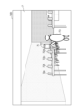
- An example of a VR image is shown in FIG. 7A.
- a plurality of user terminals including user terminals 72a, 72b, 72c, and 72d are placed in the virtual store 71.
- the user terminals 72a, 72b, 72c, and 72d are user terminals that can be selected by the user 12, and each corresponds to a user terminal that can be used in the real space and has unique model information.
- the model information of the user terminals 72a, 72b, 72c, and 72d may be the same or different.
- the user terminals 72a, 72b, 72c, and 72d have shapes (frames and display screens) based on their respective model information.
- Avatar 73 is an avatar corresponding to user 12. That is, the user 12 can freely move the avatar 73 in the virtual space by moving or operating the HMD 10 or controller 11.
- the user state detection unit 113 of the HMD 10 transmits user state information including posture information of the HMD 10 and operation information of the controller 11 to the VR content distribution device 20 via the communication unit 108 (S505).
- the VR content distribution device 20 generates VR content according to the user status information (S502) and distributes (transmits) it to the HMD 10 (S504).
- Such transmission of user status information (posture information and/or operation information) and distribution of VR content continue while the HMD 10 is logged into the system (S51).
- FIG. 7B shows an example of a VR image for selecting a user terminal to be used in the virtual space.
- the user 12 selects the user terminal 72d via the avatar 73.
- the user terminal may be selected.
- a dialog asking whether or not to select the user terminal may be displayed, and the user terminal may be selected if the user answers yes.
- FIG. 7C shows an example of an image for selecting a terminal usage mode.
- a selection area 74 is displayed superimposed on the VR image 70C.
- the selectable terminal usage modes include two types: "in-VR mode” and "superimposed display mode.”
- VR mode is a mode in which a user terminal in a virtual space is used by displaying a display screen of the user terminal by a virtual machine on the user terminal.
- in-VR mode the screen of the user terminal used by the user 12 in the virtual space can be seen (recognized) by other avatars as well.
- the "superimposed display mode” is a mode in which a user terminal is used by displaying the display screen of the user terminal by a virtual machine on an image superimposed on a virtual space (VR image). That is, the display screen of the user terminal by the virtual machine is displayed not within the virtual space but in an area separate from the virtual space.
- the screen of the user terminal used by the user 12 in the virtual space cannot be seen (recognized) by other avatars.
- the user 12 selects "VR mode” as indicated by mark 75 (S507).
- the virtual space is configured such that the user 12 uses the selected user terminal within the virtual space.
- the terminal selection detection unit 111 of the HMD 10 transmits the terminal selection information to the VR content distribution device 20 via the communication unit 108 (S508).
- the model information generation unit 213 of the VR content distribution device 20 identifies the user terminal according to the terminal selection information received from the HMD 20 via the communication unit 205, and acquires the model information of the identified user terminal from the content database 206 ( S509).
- the model information generation unit 213 outputs the model information to the content generation unit 212.
- the model information generation unit 213 transmits the model information to the screen data generation device 30 via the communication unit 205 (S510).
- the model information sent to the screen data generation device 30 corresponds to a request by the user 12 to use a user terminal having the model information (or to allocate a virtual machine having the model information).
- the content generation unit 212 of the VR content distribution device 20 obtains shape data of the user terminal associated with the model information from the content database 206.
- the content generation unit 212 displays the shape of the user terminal indicated by the shape data on the VR image as a user terminal dedicated to the avatar 73 operated by the user 12 (S511).
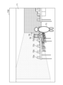
- FIG. 7D shows an example of a VR image in which a user terminal dedicated to avatar 73 operated by user 12 is displayed.
- the user terminal 76 is a user terminal dedicated to the avatar 73.
- the user terminal 76 corresponds to the user terminal 72d in the virtual store 71, and has a shape according to the model information of the user terminal 72d.
- the user terminal 76 has a display screen (display screen 77) like the user terminal 72d.
- the virtual machine management unit 311 of the screen data generation device 30 prepares a virtual machine based on the model information received from the VR content distribution device 20 via the communication unit 305 (status is “unused”). If a virtual machine with the relevant model information is stored in the RAM 303 (status is "unused"), the virtual machine is prepared; otherwise, the virtual machine management unit 311 creates a virtual machine with the relevant model information. Prepare by doing. Then, the virtual machine management unit 311 allocates the prepared virtual machine to a virtual machine for use by the user 12 (that is, the avatar 73) (S512). The virtual machine management unit 311 notifies the screen data acquisition unit 312 of the virtual machine identification information of the assigned virtual machine.
- the terminal operation detection unit 112 of the HMD 10 detects a terminal operation on the display screen 77 of the user terminal 76 displayed in the virtual store 71 (S513)
- the terminal operation detection unit 112 of the HMD 10 transmits information corresponding to the operation (terminal operation information) to the communication unit 108. via the VR content distribution device 20 (S514).
- the terminal operation transfer unit 214 of the VR content distribution device 20 transfers the terminal operation information to the screen data generation device 30 (S515).
- the operation is, for example, at least one of a tap operation (touch operation), a slide operation, and a scroll operation on the display screen 77 by the avatar 73 in the virtual space.
- the position of the tap operation becomes the terminal operation information.
- the operation position may be expressed including a three-dimensional angle.
- the screen data acquisition unit 312 of the screen data generation device 30 When the screen data acquisition unit 312 of the screen data generation device 30 receives the terminal operation information via the communication unit 305, it inputs the terminal operation information to the virtual machine assigned in S512, and from the output of the virtual machine, Screen data is acquired (S516). The acquired screen data is transmitted to the VR content distribution device 20 via the communication unit 305 (S517).
- FIG. 7E shows an example of a VR image including a display screen 77 into which screen data is embedded.
- the display screen 77 displays screen data 78 (hatched portion) that is displayed by the user 12's operation via the avatar 73.
- the HMD 10 detects (receives) information indicating the end-of-use operation by the user 12, the screen data corresponding to the terminal operation by the user 12 continues to be displayed on the display screen 77 in the virtual space (S52).
- the user status management unit 211 of the VR content distribution device 20 detects that the user status information received from the HMD 10 is information indicating an operation to end use of the user terminal in the virtual store (S519), the user status management unit 211 via the communication unit 205, A termination instruction is sent to the screen data generation device 30 (S520). This ends the use of the user terminal 76 in the virtual space by the user 12.
- the use termination operation is, for example, an operation for the avatar 73 to let go of the user terminal 76 or an operation for terminating the "in-VR mode".
- the virtual machine management unit 311 of the screen data generation device 30 When the virtual machine management unit 311 of the screen data generation device 30 receives the termination instruction from the VR content distribution device 20 via the communication unit 305, it releases the virtual machine allocated in S512 (S521). For example, the virtual machine management unit 311 changes the status of the allocated virtual machine from "in use” to "unused.” Then, with reference to the RAM 303, the number of virtual machines that implement the same type of communication device and have a status of "unused" is counted. If the number of virtual machines is less than the predetermined number, the virtual machine management unit 311 can initialize (for example, erase and recreate) the assigned virtual machine. On the other hand, if the number of virtual machines is equal to or greater than the predetermined number, the virtual machine management unit 311 can delete the assigned virtual machine. Thereafter, the HMD 10 logs out of the VR system via the VR content distribution device 20 (S522), whereby the VR content distribution device 20 ends providing the VR content to the HMD 10, and the process of S51 ends. .
- FIG. 5 shows another example of a communication sequence diagram of the HMD 10, the VR content distribution device 20, and the screen data generation device 30. Note that processes similar to those in FIG. 5 are given the same reference numerals and explanations are omitted.
- the terminal selection detection unit 111 of the HMD 10 transmits the terminal selection information to the VR content distribution device 20 via the communication unit 108 (S602).
- the model information generation unit 213 of the VR content distribution device 20 identifies the user terminal according to the terminal selection information received from the HMD 20 via the communication unit 205, and acquires the model information of the user terminal from the content database 206 (S603). .
- the model information generation unit 213 transmits the model information to the screen data generation device 30 via the communication unit 205 (S604). Furthermore, the model information generation unit 213 acquires the shape data of the user terminal associated with the model information, and transmits the shape data to the HMD 10 via the communication unit 205 (S605).
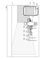
- FIG. 7F shows an example of a VR image in which a user terminal dedicated to the user is displayed in a superimposed manner.
- the user terminal 79 is a user terminal dedicated to the user 12, which is displayed superimposed on the VR image 70F.
- the user terminal 79 corresponds to the user terminal 72d in the virtual store 71, and has a shape according to the model information of the user terminal 72d.
- the user terminal 76 has a display screen (display screen 80) like the user terminal 72d. Note that the size of the user terminal 79 may be arbitrarily adjustable, and may be displayed in a larger size than usual for visibility.
- the virtual machine management unit 311 of the screen data generation device 30 prepares a virtual machine corresponding to the model information received from the VR content distribution device 20 via the communication unit 305 (status is “unused”). If a virtual machine with the relevant model information is stored in the RAM 303 (status is "unused"), the virtual machine is prepared; otherwise, the virtual machine management unit 311 creates a virtual machine with the relevant model information. Prepare by doing. Then, the virtual machine management unit 311 allocates the prepared virtual machine to a virtual machine for use by the user 12 (S607). The virtual machine management unit 311 notifies the screen data acquisition unit 312 of the virtual machine identification information of the assigned virtual machine.
- the terminal operation detection unit 112 of the HMD 10 detects a terminal operation on the display screen 80 of the user terminal 79 superimposed on the virtual store 71 (S608)
- the information corresponding to the operation is transmitted to the communication unit 108.
- the operation is, for example, at least one of a tap operation (touch operation), a slide operation, and a scroll operation on the display screen 80.
- the position of the tap operation becomes terminal operation information.
- the screen data acquisition unit 312 of the screen data generation device 30 When the screen data acquisition unit 312 of the screen data generation device 30 receives the terminal operation information via the communication unit 305, it inputs the terminal operation information to the virtual machine assigned in S512, and from the output of the virtual machine, Screen data is acquired (S516). The acquired screen data is transmitted to the VR content distribution device 20 via the communication unit 305, and transferred by the VR content distribution device 20 to the HMD 10 (S610).
- FIG. 7G shows an example of a VR image including a display screen 80 displaying screen data.
- the display screen 80 displays screen data 81 (hatched portion) that is displayed by the user 12's operation.
- the terminal operation on the display screen 80 may be an operation by the avatar 73 or may be an operation by the cursor 82 set by the display control unit 114.
- Cursor 82 can be controlled by controller 11, for example.
- the user status management unit 211 of the VR content distribution device 20 detects that the user status information received from the HMD 10 is information indicating an operation to terminate use of the user terminal in the virtual store (S519), the user status management unit 211 of the VR content distribution device 20 Then, a termination instruction is sent to the screen data generation device 30 (S520). This ends the user 12's use of the user terminal 79 superimposed on the virtual space.
- the use termination operation is, for example, an operation for terminating the "superimposed display mode.”
- the virtual machine management unit 311 of the screen data generation device 30 When the virtual machine management unit 311 of the screen data generation device 30 receives the termination instruction from the VR content distribution device 20 via the communication unit 305, it releases the virtual machine allocated in S607 (S612). For example, the virtual machine management unit 311 changes the status of the allocated virtual machine from "in use” to "unused.” Then, with reference to the RAM 303, the number of virtual machines that implement the same type of communication device and have a status of "unused" is counted. If the number of virtual machines is less than the predetermined number, the virtual machine management unit 311 can initialize (for example, erase and reconfigure) the assigned virtual machine. On the other hand, if the number of virtual machines is equal to or greater than the predetermined number, the virtual machine management unit 311 can delete the assigned virtual machine. Thereafter, the HMD 10 logs out of the VR system provided by the VR content distribution device 20 (S522), so that the VR content distribution device 20 ends providing the VR content to the HMD 10, and the process of S61
- a user can purchase items that are available in the real space in the virtual store represented in the VR image (i.e., virtual space) displayed on the HMD worn by the user.
- User terminals can be used in a pseudo manner. This allows the user to check the usability of a user terminal that can be used in the real space in the virtual space without going to a physical store in the real space.
- a virtual machine for providing screen data of a user terminal in a virtual space can be created (and deleted) in a timely manner.
- the user can select and use the user terminals he or she wants to use without worrying about the number.
- a first detection process comprising one or more processors, in which at least one of the one or more processors detects a communication device object selected from a plurality of communication device objects in a virtual space, and a virtual machine; a first display process of displaying a display screen of the same communication device as the model represented by the selected communication device object in a predetermined display area; and a first display process of detecting an operation on the display screen in the display area.
- the first display process includes displaying a new communication device object different from the plurality of communication device objects, and displaying the display screen inside the new communication device object.
- the virtual space system according to [1].
- the second detection process includes detecting at least one of a tap operation, a slide operation, and a scroll operation on the display screen of the new communication device object as the operation; [2] Or the virtual space system according to [3].
- the first display process includes displaying an image imitating a frame of a communication device, superimposed on an image representing the virtual space, and displaying the display screen inside the frame.
- the virtual space system according to [1].
- the second detection process includes detecting as the operation at least one of a tap operation, a slide operation, and a scroll operation on the display screen in the image imitating a frame of a communication device. , [5] or [6].
- At least one of the one or more processors further manages a virtual machine assigned to the selected communication device object among the plurality of virtual machines as being in use, and manages other virtual machines as being in use.
- the creation process is performed to create a virtual machine when, among the plurality of virtual machines, the number of virtual machines that implement the same model of communication device and are managed as unused is equal to or less than a predetermined number.
- At least one of the one or more processors further determines, among the plurality of virtual machines, a predetermined number of virtual machines that implement the same model of communication device and are managed as unused.
- the virtual space system according to [10] or "11" in which deletion processing for deleting at least one virtual machine is executed.
- a virtual space control method including:
- HMD Head mounted display
- 12 User
- 20 VR content distribution device
- 30 Screen data generation device
- 101 CPU, 102: ROM, 103: RAM, 104: HDD
- 105 Display unit
- 106 motion sensor
- 107 controller I/F
- 108 communication unit
- 111 terminal selection detection unit
- 112 terminal operation detection unit
- 113 user state detection unit
- 114 display control unit
- 201 CPU, 202: ROM, 203: RAM
- 205 Communication unit
- 206 Content database
- 213 Model information generation unit
- 214 Terminal operation transfer unit
- 301 CPU, 302, ROM, 303: RAM, 304: HDD
- 305 Communication department
- 311 Virtual machine management department
- 312 Image data acquisition section
- 321 Hypervisor, 331; 332; 333: Virtual machine (VM) , 341; 342; 343: Guest OS, 351;
Landscapes
- Engineering & Computer Science (AREA)
- Theoretical Computer Science (AREA)
- Software Systems (AREA)
- General Engineering & Computer Science (AREA)
- Physics & Mathematics (AREA)
- General Physics & Mathematics (AREA)
- Human Computer Interaction (AREA)
- Computer Graphics (AREA)
- Computer Hardware Design (AREA)
- Processing Or Creating Images (AREA)
- User Interface Of Digital Computer (AREA)
Abstract
Description
図1は、本実施形態による仮想空間システム1の構成例を示す。仮想空間システム1は、ヘッドマウントディスプレイ(HMD)10、VRコンテンツ配信装置20、および画面データ生成装置30から構成される。HMD10は、ユーザ(プレーヤ)12の頭部に装着可能な装置である。HMD10は、VRコンテンツ配信装置20により配信された、仮想空間を構成するVRコンテンツを出力し、ユーザ12は、当該VRコンテンツを視聴することができる。VRコンテンツは、少なくともVR画像(仮想空間を構成する画像データ)を含み、仮想空間内のオブジェクトの情報を示すメタデータや音声も含まれうる。なお、本実施形態において、画像という語は、静止画および/または動画を含むものとして理解される。ユーザ12は、VRコンテンツを視聴することで仮想空間を享受できる。VRコンテンツ配信装置20と画面データ生成装置30により、仮想現実(VR)システムが構成される。
ユーザ12は、コントローラ11を把持して入力操作を行うことにより、ユーザ12に対応するアバターの制御といった各種制御や設定を行うことができる。例えば、ユーザ12は、コントローラ11を傾けたり、コントローラ11に備えられるボタン(不図示)を押下したりすることにより、所望の入力操作を行うことができる。なお、図1では、コントローラ11は1つのハードウェアで構成される例が示されているが、右手用と左手用の2つのコントローラで構成されてもよい。また、コントローラ11は、ユーザ12によって把持されるような形態に限定されず、ユーザ12による入力操作が可能であれば、どのような形態であってもよい。
図2に、本実施形態によるHMD10(第1の情報処理装置)の構成例を示す。HMD10は、ハードウェア構成として、CPU101と、ROM102と、RAM103と、HDD104と、表示部105と、モーションセンサ106と、コントローラI/F(インタフェース)107と、通信部108を備える。HMD10はまた、外部メモリや、視線検出センサ(ユーザ12の視線の動きを検出するセンサ)を備えてよい。また、HMD10は、CPU201により実行される機能構成として、端末選択検出部111と、端末操作検出部112と、ユーザ状態検出部113と、表示制御部114を有する。
RAM(Random Access Memory)103は、揮発性メモリであり、CPU101の主メモリ、ワークエリア等として機能する。すなわち、CPU101は、処理の実行に際してROM102から必要なプログラム等をRAM103にロードし、当該プログラム等を実行することで各種の機能動作を実現する。
コントローラI/F107は、コントローラ11から、コントローラ11に対して行われたユーザ12の操作を示す情報(以下、操作情報)を検出(受信)する。例えば、コントローラI/F107は、通信部108を介して、操作情報を受信する。コントローラ11に対するユーザの操作は、例えば、コントローラ11に備えられるボタンの押下、コントローラ11の位置や向きや傾き、および/または、コントローラ11を把持する力のレベルを含む。本実施形態では、HMD10が、コントローラ11から操作情報を受信し、VRコンテンツ配信装置20に送信するように構成される。なお、コントローラ11が、操作情報をVRコンテンツ配信装置20に直接的に送信するように構成されてもよい。
端末選択検出部111は、モーションセンサ106により検出されたユーザ12の姿勢情報と、コントローラI/F107により検出されたユーザ12の操作情報のうち、端末選択に対応する情報(端末選択情報)を検出する。
さらに、端末選択情報は、ユーザ12により選択されたユーザ端末の、仮想空間における使用モード(端末使用モード)の情報を含む。端末使用モードについては後述する。
端末選択情報は、通信部108を介して、または、コントローラ11から、VRコンテンツ配信装置20に送信される。
なお、仮想空間において操作されるユーザ端末が、ラップトップのように画像を表示するエリアと操作を行うエリアが一致しないこともあるし、スマートフォンのタッチパネルのように画像を表示するエリアと操作を行うエリアが一致することもある。ゆえに、後述する表示エリアと前述の操作エリアが一致することもあるし、一致しないこともある。また、当該表示エリアと当該操作エリアが一致する場合も、少なくとも一部が一致するようにしてもよい。
また、HMD10やコントローラ11に対する所定の動きや操作が、端末操作に対応するように、あらかじめ設定されていてもよい。端末操作情報は、端末操作が行われた位置情報や3次元の角度の情報を含みうる。なお、後述するように、端末操作は、ユーザ12が、仮想空間内でユーザ端末を使用する場合と、仮想空間に対して重畳表示されたユーザ端末を使用する場合で、異なる操作となる。
さらに、本実施形態では、ユーザ状態情報は、ユーザ12により利用されていた、仮想店舗におけるユーザ端末の使用終了操作を示す情報も含む。
また、表示制御部114は、VR画像に、ユーザ12により選択されたユーザ端末の表示画面を閲覧するための画像を重畳表示しうる。当該画像は、ユーザ12により選択されたユーザ端末を模した画像としてもよい。例えば、ユーザ端末の枠と当該枠の内側に表示画面を含む画像としてもよい。さらに、表示制御部114は、画面データ生成装置30によって生成された画面データをVRコンテンツ配信装置20を介して取得し、当該画像内の表示画面に表示しうる。
図3に、本実施形態によるVRコンテンツ配信装置20(第2の情報処理装置)の構成例を示す。VRコンテンツ配信装置20は、VRコンテンツをHMD10に配信する。VRコンテンツ配信装置20が提供するVRコンテンツを利用するために、ユーザ12による所定のログイン処理(非汎用アカウントでログインするための認証処理を含む)が必要な場合、ユーザ12は、例えば、HMD10またはコントローラ11の操作により、所定の情報(例えば、IDとパスワード)を用いて、ログイン処理を行う。当該ログイン処理は、VRコンテンツ配信装置20によって行われうる。
ユーザ状態管理部211は、HMD10のユーザ状態検出部113により送信されたユーザ状態情報を、通信部205を介して検出(受信)し、コンテンツ生成部212へ出力する。なお、ユーザ状態情報が、仮想店舗におけるユーザ端末の使用終了操作を示す情報である場合、ユーザ状態管理部211は、終了指示を、通信部205を介して画面データ生成装置30へ送信する。
本実施形態では、コンテンツ生成部212は、複数のユーザ端末が置かれている仮想店舗を表すVRコンテンツを生成する。ここで、当該複数のユーザ端末のそれぞれは、識別情報を有しうる。
また、機種情報生成部213は、当該機種情報を、コンテンツ生成部212へ出力しうる。あるいは、機種情報生成部213は、当該機種情報に関連付けてコンテンツデータベース206に記憶されている、ユーザ端末の形状データを取得しうる。
図4に、本実施形態による画面データ生成装置30(第3の情報処理装置)の構成例を示す。
画面データ生成装置30は、ハードウェア構成として、CPU301と、ROM302と、RAM303と、HDD304と、通信部305を備える。また、画面データ生成装置30は、CPU301により実行される機能構成として、仮想マシン(Virtual Machine(VM))管理部311と、画面データ取得部312を有する。CPU301と、ROM302と、HDD304の基本的な構成は、図2におけるCPU101と、ROM102と、HDD104と同様のため、説明を省略する。
ゲストOSは、仮想マシンにおいて各種アプリケーションを動作させるための基本ソフトウェアである。ゲストOS341は、アプリケーション351を動作させ、ゲストOS342は、アプリケーション352を動作させ、ゲストOS343は、アプリケーション353を動作させる。
アプリケーション351は、ゲストOS341上で動作し、アプリケーション352は、ゲストOS342上で動作し、アプリケーション353は、ゲストOS343上で動作するプログラムである。。
なお、図3では、RAM303が3つの仮想マシン331、332、および333を有する例が示されているが、仮想マシンの数は特定の数に限定されない。後述するように、仮想マシン管理部311が、仮想マシンの生成や削除といった、仮想マシンの管理を行うことができる。
仮想マシン331 → メーカー名:メーカーA、機種番号:a01(Aa01)
仮想マシン332 → メーカー名:メーカーA、機種番号:a02(Aa02)
仮想マシン333 → メーカー名:メーカーB、機種番号:b01(Bb01)
図3に示す仮想マシン331、332、および333は、予め作成されていてもよいし、仮想マシン管理部311により作成されてもよい。後述するように、仮想マシン管理部311は、仮想マシンを作成する機能を有する。
仮想マシン管理部311は、RAM303に格納される仮想マシンの管理を行う。例えば、仮想マシン管理部311は、仮想マシンを作成する。具体的には、仮想マシン管理部311は、VRコンテンツ配信装置20から通信部305を介して受信した機種情報の仮想マシン(すなわち、現実空間における当該機種情報のユーザ端末の少なくとも一部の機能を仮想的に実現する仮想マシン)を作成することができる。すでに、当該受信した機種情報の仮想マシンがRAM303に記憶されている場合は、仮想マシン管理部311は、当該受信した機種情報の仮想マシンを作成せず、当該記憶されている仮想マシンを利用してもよい。また、仮想マシン管理部311は、通信部305を介して受信した所定の指示に応じて、仮想マシンを作成するように構成されてもよい。
図5を参照して、本実施形態による、仮想空間においてユーザ端末を使用する(ユーザ端末を操作する)場合の処理の流れについて説明する。図5は、HMD10と、VRコンテンツ配信装置20と画面データ生成装置30の通信シーケンス図の一例を示す。
「重畳表示モード」は、仮想空間(VR画像)に対して重畳表示された画像に、仮想マシンによるユーザ端末の表示画面を表示することにより、ユーザ端末を使用するモードである。すなわち、仮想マシンによるユーザ端末の表示画面は、仮想空間内ではなく、仮想空間とは別の領域に表示される。「重畳表示モード」では、ユーザ12が仮想空間において使用するユーザ端末の画面は、他のアバターからは見る(認識する)ことができない。
本例では、ユーザ12は、マーク75で示すように「VR内モード」を選択する(S507)。「VR内モード」が選択されることにより、ユーザ12が、選択したユーザ端末を、仮想空間内で使用するように、仮想空間が構成される。
その後、HMD10が、VRコンテンツ配信装置20を介して、VRシステムをログアウトすることにより(S522)、VRコンテンツ配信装置20は、VRコンテンツをHMD10へ提供することを終了し、S51の処理が終了する。
図6を参照して、本実施形態による、仮想空間に対して重畳表示された仮想ユーザ端末を使用する(ユーザ端末を操作する)場合の処理の流れについて説明する。図5は、HMD10と、VRコンテンツ配信装置20と画面データ生成装置30の通信シーケンス図の別の例を示す。なお、図5と同様の処理については、同じ参照符号を付して説明を省略する。
ユーザ12は、コントローラ11(および/またはHMD10)を用いて、ユーザ端末72dの、仮想空間における使用モード(端末使用モード)を選択する。本例では、図7Cに示すVR画像70C選択エリア74において、「重畳表示モード」が選択される(S601)。
なお、表示画面80に対する端末操作は、アバター73による操作であってもよいし、表示制御部114が設定したカーソル82による操作であってもよい。カーソル82は、例えば、コントローラ11によって制御されうる。
その後、HMD10が、VRコンテンツ配信装置20が提供するVRシステムをログアウトすることにより(S522)、VRコンテンツ配信装置20は、VRコンテンツをHMD10へ提供することを終了し、S61の処理が終了する。
本開示は以下の実施形態を含む。
[1]1つ以上のプロセッサを備え、前記1つ以上のプロセッサの少なくとも一つによって、仮想空間内の複数の通信装置オブジェクトから選択された通信装置オブジェクトを検出する第1検出処理と、仮想マシンによって実現された、前記選択された通信装置オブジェクトが表す機種と同じ通信装置の表示画面を、所定の表示エリアに表示する第1表示処理と、前記表示エリアの前記表示画面に対する操作を検出する第2検出処理と、前記操作を示す情報を前記仮想マシンに入力することにより、前記仮想マシンによって実現された前記通信装置の、前記操作に従って表示される表示画面を取得する取得処理と、前記操作に従って表示される前記表示画面を前記表示エリアに表示する第2表示処理と、が実行される、仮想空間システム。
Claims (14)
- 1つ以上のプロセッサ
を備え、
前記1つ以上のプロセッサの少なくとも一つによって、
仮想空間内の複数の通信装置オブジェクトから選択された通信装置オブジェクトを検出する第1検出処理と、
仮想マシンによって実現された、前記選択された通信装置オブジェクトが表す機種と同じ通信装置の表示画面を、所定の表示エリアに表示する第1表示処理と、
前記表示エリアの前記表示画面に対する操作を検出する第2検出処理と、
前記操作を示す情報を前記仮想マシンに入力することにより、前記仮想マシンによって実現された前記通信装置の、前記操作に従って表示される表示画面を取得する取得処理と、
前記操作に従って表示される前記表示画面を前記表示エリアに表示する第2表示処理と、
が実行される、仮想空間システム。 - 前記第1表示処理は、前記複数の通信装置オブジェクトとは別の新たな通信装置オブジェクトを表示することと、前記新たな通信装置オブジェクトの内側に前記表示画面を表示することを含む、
請求項1に記載の仮想空間システム。 - 前記新たな通信装置オブジェクトの形状は、前記選択された通信装置のオブジェクトと同じ形状を有する、
請求項2に記載の仮想空間システム。 - 前記第2検出処理は、前記新たな通信装置オブジェクトの前記表示画面に対するタップ操作、スライド操作、およびスクロール操作のうちの少なくともいずれかを、前記操作として検出することを含む、
請求項2に記載の仮想空間システム。 - 前記第1表示処理は、前記仮想空間を表す画像に重畳して、通信装置の枠を模した画像を表示することと、当該枠の内側に前記表示画面を表示することを含む、
請求項1に記載の仮想空間システム。 - 通信装置の枠を模した前記画像は、前記選択された通信装置オブジェクトの枠を模したものである、
請求項5に記載の仮想空間システム。 - 前記第2検出処理は、通信装置の枠を模した前記画像内の前記表示画面に対するタップ操作、スライド操作、およびスクロール操作のうちの少なくともいずれかを、前記操作として検出することを含む、
請求項5に記載の仮想空間システム。 - 前記第1表示処理は、前記複数の通信装置オブジェクトのいずれかの内側に前記表示画面を表示することを含む、
請求項1に記載の仮想空間システム。 - 前記1つ以上のプロセッサの少なくとも一つによって、さらに、
前記複数の通信装置オブジェクトそれぞれが表す機種と同じの通信装置それぞれを仮想的に実現する複数の仮想マシンを作成する作成処理と、
前記選択された通信装置オブジェクトの機種に基づき、前記複数の仮想マシンのうちのいずれかを、前記選択された通信装置オブジェクトに割り当てる割り当て処理と、
前記選択された通信装置オブジェクトの使用の終了指示に応じて、前記選択された通信装置オブジェクトに割り当てられた仮想マシンとの割り当てを解除する解除処理と、
が実行される、請求項1に記載の仮想空間システム。 - 前記1つ以上のプロセッサの少なくとも一つによって、さらに、
前記複数の仮想マシンのうち、前記選択された通信装置オブジェクトに割り当てている仮想マシンを、使用中として管理し、それ以外の仮想マシンを、未使用として管理する管理処理
が実行される、請求項9に記載の仮想空間システム。 - 前記作成処理は、前記複数の仮想マシンのうち、実現する通信装置の機種が同じであって未使用として管理されている仮想マシンの数が所定数以下の場合に、当該仮想マシンをさらに作成することを含む、
請求項10に記載の仮想空間システム。 - 前記1つ以上のプロセッサの少なくとも一つによって、さらに、
前記複数の仮想マシンのうち、実現する通信装置の機種が同じであって未使用として管理されている仮想マシンの数が所定数以上の場合に、当該仮想マシンを少なくとも一つ削除する削除処理が実行される、
請求項10に記載の仮想空間システム。 - 前記1つ以上のプロセッサの少なくとも一つによって、さらに、
前記複数の仮想マシンのうち、前記解除処理により前記割り当てが解除された仮想マシンを初期化する初期化処理が実行される、
請求項10に記載の仮想空間システム。 - 仮想空間内の複数の通信装置オブジェクトから選択された通信装置オブジェクトを検出する第1検出工程と、
仮想マシンによって実現された、前記選択された通信装置オブジェクトが表す機種と同じ通信装置の表示画面を、所定の表示エリアに表示する第1表示工程と、
前記表示エリアの前記表示画面に対する操作を検出する第2検出工程と、
前記操作を示す情報を前記仮想マシンに入力することにより、前記仮想マシンによって実現された前記通信装置の前記操作に従って表示される表示画面を取得する取得工程と、
前記操作に従って表示される前記表示画面を、前記表示エリアに表示する第2表示工程と、
を含む、仮想空間制御方法。
Priority Applications (3)
| Application Number | Priority Date | Filing Date | Title |
|---|---|---|---|
| JP2024508981A JP7787289B2 (ja) | 2022-07-28 | 2022-07-28 | 仮想空間における情報処理装置の使用のための制御 |
| PCT/JP2022/029100 WO2024024019A1 (ja) | 2022-07-28 | 2022-07-28 | 仮想空間における情報処理装置の使用のための制御 |
| US17/921,434 US12236532B2 (en) | 2022-07-28 | 2022-07-28 | Control for using information processing apparatus in virtual space |
Applications Claiming Priority (1)
| Application Number | Priority Date | Filing Date | Title |
|---|---|---|---|
| PCT/JP2022/029100 WO2024024019A1 (ja) | 2022-07-28 | 2022-07-28 | 仮想空間における情報処理装置の使用のための制御 |
Publications (1)
| Publication Number | Publication Date |
|---|---|
| WO2024024019A1 true WO2024024019A1 (ja) | 2024-02-01 |
Family
ID=89705737
Family Applications (1)
| Application Number | Title | Priority Date | Filing Date |
|---|---|---|---|
| PCT/JP2022/029100 Ceased WO2024024019A1 (ja) | 2022-07-28 | 2022-07-28 | 仮想空間における情報処理装置の使用のための制御 |
Country Status (3)
| Country | Link |
|---|---|
| US (1) | US12236532B2 (ja) |
| JP (1) | JP7787289B2 (ja) |
| WO (1) | WO2024024019A1 (ja) |
Citations (1)
| Publication number | Priority date | Publication date | Assignee | Title |
|---|---|---|---|---|
| US20150309705A1 (en) * | 2014-04-28 | 2015-10-29 | Invodo, Inc. | System and method of three-dimensional virtual commerce environments |
Family Cites Families (4)
| Publication number | Priority date | Publication date | Assignee | Title |
|---|---|---|---|---|
| US20130297281A1 (en) | 2011-10-11 | 2013-11-07 | Invodo, Inc. | Methods and systems of providing items to customers via a network |
| US11775130B2 (en) | 2019-07-03 | 2023-10-03 | Apple Inc. | Guided retail experience |
| JP2021131661A (ja) | 2020-02-19 | 2021-09-09 | グローリー株式会社 | 情報処理装置、および、情報処理方法 |
| JP2022036691A (ja) | 2020-08-24 | 2022-03-08 | 大日本印刷株式会社 | 仮想空間配信装置、コンピュータプログラム及び仮想空間配信方法 |
-
2022
- 2022-07-28 WO PCT/JP2022/029100 patent/WO2024024019A1/ja not_active Ceased
- 2022-07-28 US US17/921,434 patent/US12236532B2/en active Active
- 2022-07-28 JP JP2024508981A patent/JP7787289B2/ja active Active
Patent Citations (1)
| Publication number | Priority date | Publication date | Assignee | Title |
|---|---|---|---|---|
| US20150309705A1 (en) * | 2014-04-28 | 2015-10-29 | Invodo, Inc. | System and method of three-dimensional virtual commerce environments |
Also Published As
| Publication number | Publication date |
|---|---|
| US12236532B2 (en) | 2025-02-25 |
| US20240355056A1 (en) | 2024-10-24 |
| JP7787289B2 (ja) | 2025-12-16 |
| JPWO2024024019A1 (ja) | 2024-02-01 |
Similar Documents
| Publication | Publication Date | Title |
|---|---|---|
| CN104932677B (zh) | 互动式多驾乘者虚拟现实驾乘系统 | |
| KR101777820B1 (ko) | 헤드 마운트 디스플레이를 위한 예측적 트래킹에 기반한 인식 | |
| EP3332565B1 (en) | Mixed reality social interaction | |
| CN121548800A (zh) | 用于管理实时通信会话中的参与者的显示的系统和方法 | |
| CN120469584A (zh) | 用于操纵虚拟对象的方法 | |
| CN103918011B (zh) | 渲染系统、渲染服务器及其控制方法 | |
| CN121957350A (zh) | 用于在三维环境中显示用户界面对象的方法 | |
| US11094107B2 (en) | Information processing device and image generation method | |
| JP7424121B2 (ja) | 情報処理装置及びプログラム | |
| JP2018106499A (ja) | 仮想空間における画像の表示を制御するためにコンピュータによって実行される方法、当該方法をコンピュータに実現させるためのプログラム、および、コンピュータ装置 | |
| Karthika et al. | Hololens | |
| CN106293557B (zh) | 显示控制方法和装置 | |
| CN121195222A (zh) | 用于生物识别特征注册的设备、方法和图形用户界面 | |
| JP6113897B1 (ja) | 仮想空間を提供する方法、仮想体験を提供する方法、プログラム、および記録媒体 | |
| CN121127811A (zh) | 用于显示人的表示的设备、方法和图形用户界面 | |
| JP2004362218A (ja) | 三次元物体操作方法 | |
| JP7787289B2 (ja) | 仮想空間における情報処理装置の使用のための制御 | |
| CN114669046A (zh) | 一种控制方法和控制装置 | |
| JP2018185567A (ja) | 情報処理方法、情報処理プログラム、情報処理システムおよび情報処理装置 | |
| KR102343601B1 (ko) | 6dof 온라인 멀티 플레이어 vr 관광체험 시스템 | |
| WO2023162668A1 (ja) | 情報処理装置および床面高さ調整方法 | |
| JP6442619B2 (ja) | 情報処理装置 | |
| JP6242452B1 (ja) | 仮想空間を提供する方法、仮想体験を提供する方法、プログラム、および記録媒体 | |
| JP7841661B2 (ja) | 情報処理装置、表示システム、表示方法及び表示プログラム | |
| WO2019044688A1 (ja) | キャラクタ動画表示システム |
Legal Events
| Date | Code | Title | Description |
|---|---|---|---|
| WWE | Wipo information: entry into national phase |
Ref document number: 17921434 Country of ref document: US |
|
| WWE | Wipo information: entry into national phase |
Ref document number: 2024508981 Country of ref document: JP |
|
| 121 | Ep: the epo has been informed by wipo that ep was designated in this application |
Ref document number: 22953111 Country of ref document: EP Kind code of ref document: A1 |
|
| WWG | Wipo information: grant in national office |
Ref document number: 17921434 Country of ref document: US |
|
| NENP | Non-entry into the national phase |
Ref country code: DE |
|
| 122 | Ep: pct application non-entry in european phase |
Ref document number: 22953111 Country of ref document: EP Kind code of ref document: A1 |