WO2024023933A1 - アンテナ装置 - Google Patents
アンテナ装置 Download PDFInfo
- Publication number
- WO2024023933A1 WO2024023933A1 PCT/JP2022/028803 JP2022028803W WO2024023933A1 WO 2024023933 A1 WO2024023933 A1 WO 2024023933A1 JP 2022028803 W JP2022028803 W JP 2022028803W WO 2024023933 A1 WO2024023933 A1 WO 2024023933A1
- Authority
- WO
- WIPO (PCT)
- Prior art keywords
- arrangement
- antenna
- waves
- wave
- antenna elements
- Prior art date
- Legal status (The legal status is an assumption and is not a legal conclusion. Google has not performed a legal analysis and makes no representation as to the accuracy of the status listed.)
- Ceased
Links
Images





Classifications
-
- G—PHYSICS
- G10—MUSICAL INSTRUMENTS; ACOUSTICS
- G10L—SPEECH ANALYSIS TECHNIQUES OR SPEECH SYNTHESIS; SPEECH RECOGNITION; SPEECH OR VOICE PROCESSING TECHNIQUES; SPEECH OR AUDIO CODING OR DECODING
- G10L15/00—Speech recognition
- G10L15/28—Constructional details of speech recognition systems
-
- H—ELECTRICITY
- H04—ELECTRIC COMMUNICATION TECHNIQUE
- H04B—TRANSMISSION
- H04B7/00—Radio transmission systems, i.e. using radiation field
- H04B7/02—Diversity systems; Multi-antenna system, i.e. transmission or reception using multiple antennas
- H04B7/04—Diversity systems; Multi-antenna system, i.e. transmission or reception using multiple antennas using two or more spaced independent antennas
- H04B7/08—Diversity systems; Multi-antenna system, i.e. transmission or reception using multiple antennas using two or more spaced independent antennas at the receiving station
Definitions
- the present invention relates to a technology for receiving wireless signals transmitted using radio waves and sound waves (including ultrasonic waves).
- ISI Inter-symbol-interference
- CCI co-channel interference
- the term "antenna” is used to represent a concept that is not limited to a configuration for receiving radio waves, but also includes a configuration for receiving sound waves (including ultrasonic waves). Furthermore, in the following description, waves such as multipath waves and interference waves that may affect the reception of the desired wave (direct wave) to be received are referred to as "unnecessary waves.”
- an array antenna is equipped with an FIR (Finite Impulse Response) filter and an FB (Feed-back) filter for each array antenna, and the filter coefficients are determined using an optimization algorithm such as the LMS (Least Mean Square) method or the RLS (Recursive Least Square) method. There is a method to perform optimization.
- FIR Finite Impulse Response
- FB Breast Biharmonic Switching Function
- LMS Least Mean Square
- RLS Recursive Least Square
- the suppression performance of unnecessary waves in the spatial domain is fundamentally determined by the shape of the array antenna. Since the size of the aperture of the array antenna determines the spatial resolution, generally speaking, the wider the aperture, the better the unnecessary wave suppression performance. In other words, the larger the overall size of the array antenna, the more effectively it is possible to suppress unnecessary waves that have a small angular difference from the desired wave.
- Spatial aliasing means that when the direction of arrival of a signal is expressed as a vector by using the phase difference between antenna elements, a combination of linearly dependent directions of arrival occurs.
- a vector indicating the direction of arrival of a signal will be referred to as a "steering vector.”
- antenna elements may not be arranged at intervals of half a wavelength or less depending on the aperture width of the array depending on the angular resolution.
- spatial aliasing may occur within the transmission frequency band depending on the arrangement pattern. Specifically, there are the following cases.
- the present invention aims to provide a technology that can improve the performance of equalization processing performed when receiving desired waves that are radio waves or sound waves (including ultrasonic waves) to be received.
- One aspect of the present invention includes N antenna elements (N is an integer of 3 or more) that receive sound waves or radio waves, and the antenna elements each have a steering vector corresponding to an incident angle ⁇ of a certain sound wave or radio wave, and a steering vector corresponding to an incident angle ⁇ of a certain sound wave or radio wave.
- This is an antenna device in which the steering vector corresponding to the incident angle ⁇ _d ( ⁇ _d is ⁇ /2 to + ⁇ /2) of the sound wave or radio wave is located at a position that is not linearly dependent.
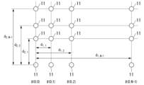
- FIG. 3 is a diagram showing a specific example of the arrangement of antenna elements 11 in the antenna device 10 configured as an array antenna.
- 1 is a diagram showing a configuration example of a receiving system 100.
- FIG. It is a figure showing an outline of computer simulation. It is a figure showing an outline of computer simulation. These are the specifications of the transmission signal in computer simulation. These are the specifications of antenna placement for comparative evaluation using computer simulation.
- FIG. 3 shows a comparison of sequences. These are simulation results.
- FIG. 3 is a diagram showing a first specific example of a two-dimensional arrangement. It is a figure which shows the second specific example of two-dimensional arrangement
- FIG. 1 is a diagram showing a specific example of the arrangement of antenna elements 11 in an antenna device 10 configured as an array antenna.
- the antenna device 10 includes at least three antenna elements 11.
- the antenna element 11 receives waves such as radio waves and sound waves (including ultrasonic waves) and generates electrical signals corresponding to the waves.
- the antenna element 11 is arranged one-dimensionally or two-dimensionally. With this arrangement, the antenna device 10 is configured as an array antenna. In the example of FIG. 1, N antenna elements 11 are arranged on a one-dimensional line. That is, the antenna device 10 in the example of FIG. 1 is configured as a linear array. Each antenna element 11 is given a code from #0 to #N-1.
- the #i antenna element is placed d_i away.
- the description "A_B” indicates a description in which "B” is placed as a subscript at the lower right of "A”. It is assumed that the received waves (including desired waves and unnecessary waves) are incident from any direction at an angle ⁇ ( ⁇ is ⁇ /2 to + ⁇ /2).
- Equation 1 When the steering vector corresponding to the incident angle ⁇ and the steering vector corresponding to another arrival direction ⁇ _d ( ⁇ _d is ⁇ /2 to + ⁇ /2) are linearly dependent, the following conditional expression (Equation 1) is satisfied. It is filled.
- ⁇ is a wavelength corresponding to any frequency within the transmission band.
- the transmission band refers to a band that is assumed to be used in transmitting a desired wave (direct wave) to be received.
- the numerical range of each ⁇ _n is shown by Equation 2 below.
- Equation 3 By rearranging Equation 1, the following Equation 3 can be obtained.
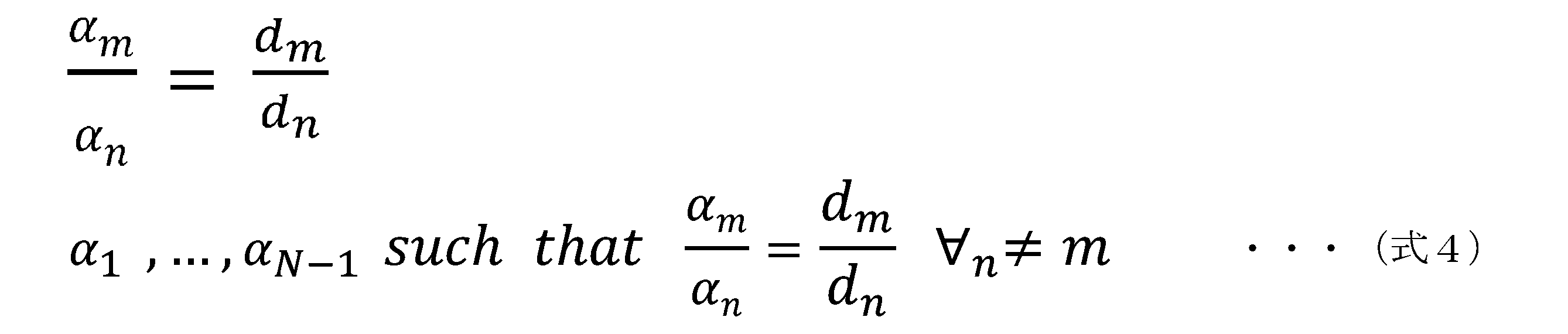
- m and n are each a set of integers from 1 to (N-1). For all pairs of m and n where m and n are different, if there is at least one set of ⁇ _1, ..., ⁇ _(N-1) that satisfies Equation 4 shown below, in a direction different from the incident angle ⁇ . One or more linearly dependent directions of arrival occur. In other words, when ⁇ _1 to ⁇ _(N-1) form a set that satisfies Expression 3, one or more linearly dependent arrival directions occur in a direction different from the incident angle ⁇ .
- the ratio of the element spacing (d_n'/d_m') of at least one of the set of d_n and d_m is an irrational number
- the arrangement of the antenna element 11 under such conditions is called a first arrangement.
- d_1 be a value that is 1/2 or more of the minimum wavelength within the transmission band and less than the minimum wavelength.
- ⁇ _1 can only take +1 or ⁇ 1 for all wavelengths within the transmission band.
- d_2 is arranged so that it is not an integral multiple of d_1, linear dependence of the steering vectors will not occur.
- the arrangement of the antenna element 11 under such conditions is called a second arrangement.
- equation 5 can be obtained from the inequality evaluation of equation 2.
- ⁇ _min is the minimum wavelength within the transmission band.
- FIG. 2 is a diagram showing a configuration example of the receiving system 100.
- the receiving system 100 includes an antenna device 10 and a receiving device 20.
- the antenna device 10 is an array antenna.
- the antenna device 10 includes at least three or more antenna elements 11.
- the number of antenna elements 11 included in the antenna device 10 is expressed as N (N is an integer of 3 or more).
- the N antenna elements 11 are arranged so as not to satisfy the above-mentioned linear dependency generation condition (Equation 4) of the steering vector.
- the antenna elements 11 may be arranged in a one-dimensional array or a two-dimensional array.
- the receiving device 20 includes N converters 201 (201_1 to 201_N), N FF filters 202 (202_1 to 202_N), a combiner 203, an output estimation unit 204, and a filter coefficient acquisition unit 205.
- N is the same value as the number of antenna elements 11 that the antenna device 10 has. In this way, it is desirable that the number of conversion units 201 and FF filters 202 is the same as the number of antenna elements 11. If some functions are not used, they do not necessarily have to be the same number. Note that, in the following description, the configurations common to the N devices with the same name will be described with symbols such as "_1" omitted. For example, regarding the conversion unit, it is written as “conversion unit 201” instead of “conversion unit 201_1”.
- the conversion unit 201 samples the electrical signal converted by the antenna element 11 of the antenna device 10. Specifically, the details are as follows. The conversion unit 201 performs analog-to-digital conversion on the electrical signal converted by the antenna element 11. The conversion unit 201 then performs frequency conversion on the digital signal obtained by analog-to-digital conversion. Note that other configurations (modifications) may be adopted for the conversion unit 201. For example, the conversion unit 201 may be configured to perform only analog-to-digital conversion. For example, the conversion unit 201 may be configured to perform frequency conversion on an analog signal and then perform analog-to-digital conversion.
- the FF filter 202 performs waveform manipulation on the signal sampled by the conversion unit 201.
- the FF filter 202 outputs the waveform-manipulated signal to the synthesizer 203.
- the synthesizer 203 synthesizes the N signals whose waveforms have been manipulated by the FF filter 202.
- the output estimation unit 204 may tentatively determine the output of the combiner 203 based on the signals combined by the combiner 203.
- the output estimation unit 204 may calculate a desired response by using the signal combined by the combiner 203 and the training signal.
- the desired response may be, for example, a symbol included in a desired wave signal received by the antenna device 10.
- the filter coefficient acquisition unit 205 adaptively acquires the filter coefficients of the N FF filters 202.
- the filter coefficient acquisition unit 205 may acquire the filter coefficients by calculation, for example, or may acquire the filter coefficients based on a preset lookup table.
- the filter coefficient acquisition unit 205 may be configured to include, for example, an error calculation unit and an adaptive algorithm unit.
- the error calculation unit calculates the error between the output of the equalizer and the desired response.
- the adaptive algorithm section adaptively updates the filter coefficients based on the error calculated by the error calculation section, and optimizes the filter coefficients based on a criterion such as least square error.
- the adaptive algorithm includes means for recursively calculating filter coefficients, such as the LMS (least mean square) method, the RLS (recursive least square) method, and the APA (Affine projection algorithm) method. It also includes algorithms derived from these.
- the output estimation section 204 and the filter coefficient acquisition section 205 are each configured using a processor such as a CPU and a memory.
- the output estimation unit 204 and the filter coefficient acquisition unit 205 operate when a processor reads and executes a program stored in a storage device.
- the program may be recorded on a computer-readable recording medium.
- the computer-readable recording medium is a non-temporary storage medium such as a flexible disk, a magneto-optical disk, a ROM, a CD-ROM, or other portable medium, or a hard disk or other storage device built into a computer system.
- the program may be transmitted via a telecommunications line.
- a part or all of the operations of the output estimation section 204 and the filter coefficient acquisition section 205 may be realized using hardware including an electronic circuit using an LSI, an ASIC, a PLD, an FPGA, or the like, for example.
- the receiving device 20 may further include an FB filter and a DPLL (digital PLL), as shown in Non-Patent Documents 1 and 2.
- a DPLL digital PLL
- the configuration of the antenna device 10 will be described in detail.
- the arrangement of the antenna elements 11 in the antenna device 10 does not create a set of linearly dependent arrival directions whose steering vectors completely match. Therefore, there are FF filter coefficients whose gains in any two directions do not match. That is, independent control in two directions is possible, such as making the reception gain of unnecessary waves smaller than that of desired waves, regardless of the combination of arrival directions. As a result, the degree of freedom in controlling the adaptive algorithm increases, and it becomes possible to effectively suppress unnecessary waves and extract desired waves.
- the first arrangement is characterized in that there is at least one combination of spacings between antenna elements 11 that are irrational ratios.
- the antenna elements 11 may be arranged so as to satisfy Equation 6 below.
- the installation interval of the antenna elements 11 is an approximate value of an irrational number ratio, so a value that sufficiently approximates an irrational number may be used.
- d_1 is greater than or equal to 1/2 of the minimum wavelength within the transmission band and less than the minimum wavelength. Further, at least one of d_2 to d_(N-1) is not an integral multiple of d_1.
- the antenna element 11 is configured such that any n (n is 2 or more and less than (N-1)) satisfies the following formula 7 and that d_n and kd_1 are different (k is a natural number). is placed.
- both p_n' and p_m' are (2d_(N-1)).
- p_n' and p_m' are (2d_(N-1)).
- 3 and 4 are diagrams showing an overview of computer simulation.
- a linear array is assumed, and a direct wave (desired wave) is incident from a direction perpendicular to the arrangement direction of the linear array.
- a multipath wave delayed by 100 symbols is made incident from the ⁇ direction ( ⁇ is a value between 0 and ⁇ /2).
- the equalizer has the same configuration as shown in FIG. 2, and extracts direct waves and removes multipath waves based on the training sequence.
- Equalization performance is evaluated by evaluating the mean square error (MSE) between the desired signal and the output value of the equalizer.
- MSE mean square error
- the table shown in FIG. 5 is the specifications of the transmission signal in the computer simulation.
- the table shown in FIG. 6 is the specifications of the antenna arrangement for comparative evaluation by computer simulation.
- the aperture diameter of the array antenna is set to 1 m in common to all four patterns of arrangement. Equal spacing is a common array to compare and has a linear dependence on the steering vector.
- Figure 8 shows the simulation results.
- the horizontal axis represents the arrival direction of the delayed wave
- the vertical axis represents the mean square error with respect to the desired signal (the signal indicated by the desired wave). It can be said that the smaller the mean squared error, the more effectively interference caused by unnecessary waves can be removed.
- the results show that in the equally spaced arrangement, the interference wave suppression performance deteriorates after the angle (8.7 degrees) at which spatial aliasing occurs at the highest frequency of the band (30 kHz).
- the first to third arrangements achieve better performance than the equally spaced arrangement at arrival angles of 10 degrees or more, and the equalization performance is improved.
- wavelengths often differ by more than twice the length within a frequency band.
- the above problem becomes more serious in underwater communications because the relationship between directions of arrival that causes spatial aliasing differs for each wavelength within the band, making it difficult to remove unnecessary waves from all directions.
- the accuracy of equalization processing for the received signal can be improved by using the antenna device 10 that adopts one of the first arrangement, second arrangement, and third arrangement as described above. becomes possible.
- the antenna elements 11 in the antenna device 10 are arranged one-dimensionally, but the antenna elements 11 may be arranged two-dimensionally. In this case, the beam is scanned two-dimensionally, and it works effectively against interference waves from two directions: elevation and azimuth.
- FIG. 9 is a diagram showing a first specific example of a two-dimensional arrangement.
- FIG. 10 is a diagram showing a second specific example of two-dimensional arrangement.
- the antenna elements 11 are arranged in one row along the first axis and in one row along the second axis.
- the first axis and the second axis are orthogonal.
- the antenna elements 11 are arranged in an L-shape.
- a cross array or other two-dimensional array may be used.
- each of the first axis and the second axis may not be arranged in one row, but may be arranged in a plurality of rows.
- the antenna elements 11 are arranged in a rectangular shape along the first axis and the second axis.
- the arrangement interval d_(1,1) to d_(1,N-1) does not satisfy the condition of Equation 4, and the arrangement interval d_(2,1) to d_(2 , N-1) does not satisfy the condition of Equation 4.
- any of the first to third arrangements may be used.
- the set of arrangement intervals d_(2,1) to d_(2,N-1) may be any one of the first arrangement to the third arrangement.
- the arrangement pattern from d_(1,1) to d_(1,N-1) and the arrangement pattern from d_(2,1) to d_(2,N-1) are the same.
- the set from d_(1,1) to d_(1,N-1) is the first arrangement, and the set from d_(2,1) to d_(2,N-1) is also the first arrangement. may be configured respectively.
- the set from d_(1,1) to d_(1,N-1) is the first arrangement, and the set from d_(2,1) to d_(2,N-1) is the second arrangement. Each may be configured as an arrangement.
- the set from d_(1,1) to d_(1,N-1) does not satisfy the condition of Equation 4, and the set from d_(2,1) to d_(2,N-1) It may be configured to satisfy the condition of Expression 4. Furthermore, the set of arrangement intervals d_(1,1) to d_(1,N-1) satisfies the condition of formula 4, and the set of arrangement intervals d_(2,1) to d_(2,N-1) satisfies the condition of formula 4. The configuration may be such that condition 4 is not satisfied.
- the set of the above-mentioned arrangement intervals d_(1,1) to d_(1,N-1) does not satisfy the condition of Equation 4, and the set of the arrangement intervals d_(2,1) to d_(2,N-1) -1) may also have lower performance than a configuration that does not satisfy the condition of Equation 4, but it is possible to improve the performance at least more than the conventional configuration.
- FIG. 7 they may be arranged in a two-dimensional mesh grid.
- the arrangement shown in FIGS. 9 and 10 does not have a linearly dependent set of steering vectors in any two-dimensional direction. Therefore, it is possible to improve equalization performance.
- the first axis and the second axis are orthogonal, but they do not necessarily need to be orthogonal.
- the present invention can be applied to techniques for receiving radio waves and sound waves (including ultrasonic waves).
Landscapes
- Engineering & Computer Science (AREA)
- Computational Linguistics (AREA)
- Health & Medical Sciences (AREA)
- Audiology, Speech & Language Pathology (AREA)
- Human Computer Interaction (AREA)
- Physics & Mathematics (AREA)
- Acoustics & Sound (AREA)
- Multimedia (AREA)
- Computer Networks & Wireless Communication (AREA)
- Signal Processing (AREA)
- Variable-Direction Aerials And Aerial Arrays (AREA)
Abstract
本発明の一態様は、音波又は電波を受信するN個(Nは3以上の整数)のアンテナ素子を備え、前記アンテナ素子は、ある音波又は電波の入射角度θに対応するステアリングベクトルと、他の音波又は電波の入射角度θ_d(θ_dは-π/2~+π/2)に対応するステアリングベクトルと、が一次従属にならない位置に配置されている、アンテナ装置である。
Description
本発明は、電波や音波(超音波を含む)を用いて伝送される無線信号を受信する技術に関する。
比帯域が数十%を超える広帯域の水中音響通信システムでは、海面や海底からのマルチパス波によって生じるISI(Inter-symbol-interference)や他システムからの干渉波によって生じるCCI(co-channel interference)によって波形が歪みやすい。そのため、このような水中音響通信システムでは、受信機で等化処理を行う必要がある。このような等化処理は、水中での音響通信特有のものではなく、電波を用いた通信でも行われる。
なお、以下の説明では“アンテナ”という文言を、電波を受信するための構成に限らず、音波(超音波を含む)を受信するための構成も含む概念を表す文言として用いる。また、以下の説明では、マルチパス波及び干渉波のように、受信対象となっている所望波(直接波)の受信に影響を及ぼす可能性のある波を「不要波」という。
アレーアンテナを用いた信号処理では、時空間領域の双方を活用して不要波の除去を行うことができる。そのため、一般的な時間領域の等化器に比べて、アレーアンテナを用いた信号処理では補償効果が高い。したがって、水中通信ではアレーアンテナを用いた信号処理が用いられることがある。例えば、アレーアンテナ個別のFIR(Finite impulse response)フィルターとFB(Feed-back)フィルターとを備え、フィルター係数をLMS(Least mean square)法やRLS(Recursive least square)法等の最適化アルゴリズムを用いて最適化を行う方法がある。(例えば、非特許文献1や非特許文献2を参照)。フィルター係数の制御によって、周波数―空間方向の利得を制御することができる。そして、周波数―空間方向の利得を制御することで所望波を抽出し、不要波を除去することができる。
空間領域における不要波の抑圧性能は、根本的にはアレーアンテナの形状で決まる。アレーアンテナの開口の大きさが空間分解能を決定するため、一般的には開口を広くした方が不要波の抑圧性能が向上する。換言すれば、アレーアンテナ全体の大きさが大きいほど、所望波と角度差が小さい不要波をより有効に抑圧できる。
ただし、伝送周波数帯域において空間エイリアシングが発生しないように、帯域の最も短い波長(最も高い周波数)の半波長以下の間隔でアンテナ素子を配列する必要がある。空間エイリアシングとは、アンテナ素子間の位相差を用いることで信号の到来方向をベクトルで表現したときに、一次従属な到来方向の組み合わせが生じることである。以下の説明では、信号の到来方向を示すベクトルを「ステアリングベクトル」という。
M. Johnson, L. Freitag and M. Stojanovic, "Improved Doppler tracking and correction for underwater acoustic communications," 1997 IEEE International Conference on Acoustics, Speech, and Signal Processing, 1997, pp. 575-578 vol.1, doi: 10.1109/ICASSP.1997.599703.
H. Fukumoto, Y. Fujino, M. Nakano, K. Sakamoto and T. Tsubaki, "Field Experiments Demonstrating Mbps-Class Underwater Acoustic Communication with Spatio-Temporal Equalization," Global Oceans 2020: Singapore - U.S. Gulf Coast, 2020, pp. 1-6, doi: 10.1109/IEEECONF38699.2020.9389018.
しかしながら、装置の制約等が原因となり、角度分解能に応じたアレーの開口幅に応じて、半波長以下の間隔でアンテナ素子を配置できない場合がある。この場合、配列パターンによっては伝送周波数帯域内に空間エイリアシングが生じる可能性がある。具体的には、以下のようなケースがある。
所望波と不要波との到来方向を示すステアリングベクトルが一次従属のとき、等化器が不要波に対して空間的にヌル形成しようとすると、所望波方向にもヌル形成されてしまう。一方で、所望波方向にメインローブを向けると、不要波の到来方向にもメインローブが向けられてしまい、不要波を抑圧できない。そのため、どのような適応アルゴリズムを用いてフィルター係数を最適化したとしても、不要波の抑圧も所望波の抽出も効果的に行うことができず、等化の性能が低下してしまう。
上記事情に鑑み、本発明は、受信対象となる電波や音波(超音波を含む)である所望波を受信する際に行われる等化処理の性能を向上可能な技術の提供を目的としている。
本発明の一態様は、音波又は電波を受信するN個(Nは3以上の整数)のアンテナ素子を備え、前記アンテナ素子は、ある音波又は電波の入射角度θに対応するステアリングベクトルと、他の音波又は電波の入射角度θ_d(θ_dは-π/2~+π/2)に対応するステアリングベクトルと、が一次従属にならない位置に配置されている、アンテナ装置である。
本発明により、受信対象となる電波や音波(超音波を含む)である所望波を受信する際に行われる等化処理の性能を向上させることが可能となる。
[ステアリングベクトルの一次従属性の発生条件]
アレーアンテナとして構成されるアンテナ装置において、空間エイリアシングによってステアリングベクトルの一次従属性が発生する条件について説明する。図1は、アレーアンテナとして構成されるアンテナ装置10におけるアンテナ素子11の配列の具体例を示す図である。アンテナ装置10は、少なくとも3つのアンテナ素子11を備える。アンテナ素子11は、電波や音波(超音波を含む)等の波を受けて、波に応じた電気信号を生成する。
アレーアンテナとして構成されるアンテナ装置において、空間エイリアシングによってステアリングベクトルの一次従属性が発生する条件について説明する。図1は、アレーアンテナとして構成されるアンテナ装置10におけるアンテナ素子11の配列の具体例を示す図である。アンテナ装置10は、少なくとも3つのアンテナ素子11を備える。アンテナ素子11は、電波や音波(超音波を含む)等の波を受けて、波に応じた電気信号を生成する。
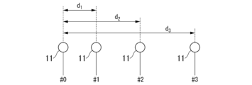
アンテナ素子11は、一次元又は二次元に配置される。このような配置により、アンテナ装置10はアレーアンテナとして構成される。図1の例では、一次元のライン上にN個のアンテナ素子11が配置されている。すなわち、図1の例におけるアンテナ装置10は線形アレーとして構成されている。各アンテナ素子11には、#0~#N-1の符号が与えられている。
#0のアンテナ素子11を基準点として、#iのアンテナ素子はd_i離れた位置に配置される。なお、“A_B”という記載は、“A”の右下に添え字として“B”が配置された記載を示す。受信波(所望波及び不要波を含む)は、角度θ(θは-π/2~+π/2)のいずれかの方向から入射するものと仮定する。
入射角度θに対応するステアリングベクトルと、他の到来方向θ_d(θ_dは-π/2~+π/2)に対応するステアリングベクトルと、が一次従属である場合、以下の条件式(式1)が満たされる。

ここで、λは伝送帯域内のいずれかの周波数に対応する波長である。伝送帯域とは、受信対象となっている所望波(直接波)の伝送において使用されることが想定されている帯域を示す。α_n(n=0,…,N-1)は0を除く整数である。各α_nの数値範囲は以下の式2で示される。

式1を整理することによって、以下の式3を得ることができる。

m及びnは、それぞれ1以上(N-1)以下の整数の集合である。mとnとが異なる全てのm及びnのペアについて、以下に示す式4を満たすα_1,…,α_(N-1)の組が少なくとも一つ存在する場合、入射角度θと別の方向に1つ以上の一次従属な到来方向が生じる。言い換えれば、α_1~α_(N-1)が式3を満たす組となる場合には、入射角度θと別の方向に1つ以上の一次従属な到来方向が生じる。
[ステアリングベクトルの一次従属性が発生しない条件]
次に、ステアリングベクトルの一次従属性が発生しない条件について説明する。伝送帯域内でステアリングベクトルの一次従属性が発生しない条件は、-π/2~+π/2の任意のθについて、上述した式4を満たさないd_n及びd_mの組が少なくとも一つ存在することである。
次に、ステアリングベクトルの一次従属性が発生しない条件について説明する。伝送帯域内でステアリングベクトルの一次従属性が発生しない条件は、-π/2~+π/2の任意のθについて、上述した式4を満たさないd_n及びd_mの組が少なくとも一つ存在することである。
例えば、d_n及びd_mの組の少なくとも一つの素子間隔の比(d_n’/d_m’)が無理数であれば、θの値によらずに式4の条件を満たす整数比が存在しない。そのため、このように素子間隔の比が無理数であれば、ステアリングベクトルの一次従属性は、全ての角度及び全ての波長について発生しない。このような条件におけるアンテナ素子11の配置を、第一配置と呼ぶ。
例えば、d_1を伝送帯域内の最小波長の1/2以上、且つ、最小波長未満の値とする。この場合、伝送帯域内の全ての波長について、α_1は+1か-1しか取りえない。d_2をd_1の整数倍でないように配置すれば、ステアリングベクトルの一次従属性は発生しない。このような条件におけるアンテナ素子11の配置を、第二配置と呼ぶ。
例えば、式2の不等式評価から以下の式5を得ることができる。
例えば、式2の不等式評価から以下の式5を得ることができる。

ここで、λ_minは伝送帯域内における最小の波長である。式5より以下の事象を導きだすことができる。d_nとd_mとの比を、互いに素な数p_n及びp_mを用いて、d_n/d_m=p_n/p_mと表した場合、p_n及びp_mのいずれもが(2d_(N-1))/λ_min よりも大きければ、式4を満たす整数α_n及びα_mの組は存在しない。すなわち、上述した条件を満たすことにより、ステアリングベクトルの一次従属性は発生しない。このような条件におけるアンテナ素子11の配置を、第三配置と呼ぶ。
[受信システムの構成]
次に、アンテナ装置10を含む受信システム100について説明する。図2は、受信システム100の構成例を示す図である。受信システム100は、アンテナ装置10及び受信装置20を備える。
次に、アンテナ装置10を含む受信システム100について説明する。図2は、受信システム100の構成例を示す図である。受信システム100は、アンテナ装置10及び受信装置20を備える。
アンテナ装置10はアレーアンテナである。アンテナ装置10は、少なくとも3以上のアンテナ素子11を備える。以下の説明では、アンテナ装置10が備えるアンテナ素子11の数をN(Nは3以上の整数)として表す。アンテナ装置10において、N個のアンテナ素子11は、上述したステアリングベクトルの一次従属発生条件(式4)を満たさないように配置される。アンテナ素子11の配置は、一次元のアレー配置であってもよいし、二次元のアレー配置であってもよい。
受信装置20は、N台の変換部201(201_1~201_N)、N台のFFフィルター202(202_1~202_N)、合成器203、出力推定部204及びフィルター係数取得部205を備える。Nは、アンテナ装置10が有するアンテナ素子11の数と同じ値である。このように、変換部201及びFFフィルター202は、それぞれアンテナ素子11と同数設けられることが望ましい。一部の機能を使用しないのであれば、必ずしも全てが同数である必要はない。なお、以下の説明では、N台の同名の装置に共通する構成に関しては、“_1”等の符号を省略して記載する。例えば、変換部に関しては、“変換部201_1”ではなく、“変換部201”と記載する。
変換部201は、アンテナ装置10のアンテナ素子11によって変換された電気信号のサンプリングを行う。具体的には以下の通りである。変換部201は、アンテナ素子11によって変換された電気信号に対し、アナログデジタル変換を行う。そして、変換部201は、アナログデジタル変換によって得られたデジタル信号について、周波数変換を行う。なお、変換部201には他の構成(変形例)が採用されてもよい。例えば、変換部201は、アナログデジタル変換のみを行うように構成されてもよい。例えば、変換部201は、アナログ信号に対して周波数変換を行い、その後にアナログデジタル変換を行うように構成されてもよい。
FFフィルター202は、変換部201によってサンプリングされた信号に対して波形操作を行う。FFフィルター202は、波形操作された信号を合成器203に出力する。
合成器203は、FFフィルター202によって波形操作が行われた後のN個の信号を合成する。
出力推定部204は、合成器203によって合成された後の信号に基づいて、合成器203の出力を仮判定してもよい。出力推定部204は、合成器203によって合成された後の信号とトレーニング信号とを用いることで、所望の応答を計算してもよい。所望の応答とは、例えばアンテナ装置10によって受信された所望波の信号に含まれるシンボルであってもよい。
フィルター係数取得部205は、N個のFFフィルター202のフィルター係数を適応的に取得する。フィルター係数取得部205は、例えば計算によってフィルター係数を取得してもよいし、予め設定されたルックアップテーブルに基づいてフィルター係数を取得してもよい。
フィルター係数取得部205は、例えば誤差計算部及び適応アルゴリズム部を含むように構成されてもよい。誤差計算部は、等化装置の出力と所望の応答との誤差を計算する。適応アルゴリズム部は、誤差計算部によって計算された誤差に基づいてフィルター係数を適応的に更新し、最小二乗誤差などの規範に基づき最適化する。適応アルゴリズムとは、LMS(least mean square)法、RLS(recursive least square)法、APA(Affine projection algorithm)法など再帰的にフィルタ係数を算出する手段を含む。また、これらの派生したアルゴリズムも含む。
出力推定部204及びフィルター係数取得部205は、それぞれCPU等のプロセッサーやメモリを用いて構成される。出力推定部204及びフィルター係数取得部205は、記憶装置に記憶されたプログラムをプロセッサーが読み出して実行することによって動作する。プログラムは、コンピューター読み取り可能な記録媒体に記録されてもよい。コンピューター読み取り可能な記録媒体とは、例えばフレキシブルディスク、光磁気ディスク、ROM、CD-ROM等の可搬媒体、コンピューターシステムに内蔵されるハードディスク等の記憶装置などの非一時的な記憶媒体である。プログラムは、電気通信回線を介して送信されてもよい。出力推定部204及びフィルター係数取得部205の動作の一部又は全部は、例えば、LSI、ASIC、PLD又はFPGA等を用いた電子回路を含むハードウェアを用いて実現されてもよい。
なお、受信装置20は、非特許文献1及び2に示されるように、FBフィルターとDPLL(デジタルPLL)をさらに備えてもよい。
[アンテナ装置の詳細]
次に、アンテナ装置10の構成について詳細に説明する。上述したように、アンテナ装置10におけるアンテナ素子11の配置では、ステアリングベクトルが完全に一致する一次従属な到来方向の組が生じない。したがって、任意の2方向の利得が一致しないFFフィルター係数が存在する。すなわち、到来方向の組み合わせによらず、不要波の受信利得を所望波よりも小さくするといった2方向の独立制御が可能である。その結果、適応アルゴリズムにおける制御の自由度が高まり、不要波の抑圧と所望波の抽出とを効果的に行うことが可能となる。
次に、アンテナ装置10の構成について詳細に説明する。上述したように、アンテナ装置10におけるアンテナ素子11の配置では、ステアリングベクトルが完全に一致する一次従属な到来方向の組が生じない。したがって、任意の2方向の利得が一致しないFFフィルター係数が存在する。すなわち、到来方向の組み合わせによらず、不要波の受信利得を所望波よりも小さくするといった2方向の独立制御が可能である。その結果、適応アルゴリズムにおける制御の自由度が高まり、不要波の抑圧と所望波の抽出とを効果的に行うことが可能となる。
上述したように、アンテナ素子11の配列の具体例として、第一配置、第二配置及び第三配置がある。それぞれの具体例について説明する。
[第一配置]
第一配置では、無理数比となるアンテナ素子11の間隔の組み合わせが少なくとも一つ存在することを特徴とする。例えば、以下の式6を満たすようにアンテナ素子11が配列されてもよい。
第一配置では、無理数比となるアンテナ素子11の間隔の組み合わせが少なくとも一つ存在することを特徴とする。例えば、以下の式6を満たすようにアンテナ素子11が配列されてもよい。

式6において、d_n、d_mは、図1に示されるとおりである。M_oは無理数である。n及びmは互いに異なる1以上(N-1)以下の整数である。式6の条件によれば、d_n/d_m=1/M_oである。このように、式6を満たすようにアンテナ素子11が配列されることによって、d_n/d_mが無理数比となる。そのため、式4を満たさない。その結果、常にステアリングベクトルの一次従属が発生しない。
なお、実運用上、アンテナ素子11の設置間隔は無理数比の近似値となることから、無理数を十分に近似した値が用いられてもよい。
[第二配置]
第二配置では、d_1は伝送帯域内の最小波長の1/2以上、且つ、最少波長未満とする。また、d_2からd_(N-1)のうちの少なくとも一つが、d_1の整数倍ではない。つまり、以下の式7を満たし、且つ、d_nとkd_1とが異なる(kは自然数)、という条件を、いずれかのn(nは2以上(N-1)未満)で満たすようにアンテナ素子11が配置される。
第二配置では、d_1は伝送帯域内の最小波長の1/2以上、且つ、最少波長未満とする。また、d_2からd_(N-1)のうちの少なくとも一つが、d_1の整数倍ではない。つまり、以下の式7を満たし、且つ、d_nとkd_1とが異なる(kは自然数)、という条件を、いずれかのn(nは2以上(N-1)未満)で満たすようにアンテナ素子11が配置される。

[第三配置]
第三配置では、d_nとd_mとの組の少なくとも一つのアンテナ素子間隔の比を互いに素な因数p_n’/p_m’で表したときに、p_n’もp_m’も(2d_(N-1))/λ_min よりも大きい値となる配置である。つまり、d_n=γP_n,d_m=γP_m 、γは実数、P_n,P_m は互いに素な整数であり、以下の式8の条件を満たす、という条件を、いずれかのn,m(nとmは1以上(N-1)以下)の組で満たすようにアンテナ素子11が配列される。
第三配置では、d_nとd_mとの組の少なくとも一つのアンテナ素子間隔の比を互いに素な因数p_n’/p_m’で表したときに、p_n’もp_m’も(2d_(N-1))/λ_min よりも大きい値となる配置である。つまり、d_n=γP_n,d_m=γP_m 、γは実数、P_n,P_m は互いに素な整数であり、以下の式8の条件を満たす、という条件を、いずれかのn,m(nとmは1以上(N-1)以下)の組で満たすようにアンテナ素子11が配列される。

[実施例]
次に、上述した第一配置、第二配置及び第三配置の各アンテナ装置10を用いた受信システム100について、一般的な等間隔配置のアンテナ装置を用いた受信システムと効果について計算機シミュレーションした結果を示す。
次に、上述した第一配置、第二配置及び第三配置の各アンテナ装置10を用いた受信システム100について、一般的な等間隔配置のアンテナ装置を用いた受信システムと効果について計算機シミュレーションした結果を示す。
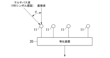
図3及び図4は、計算機シミュレーションの概要を示す図である。本シミュレーションでは、線形アレーを仮定し、線形アレーの配列方向と直交した方向から直接波(所望波)を入射させる。さらに、100シンボル遅延したマルチパス波をθ(θは0からπ/2の間の値)方向から入射させる。等化装置は図2に示される構成と同一であり、トレーニング系列を基に直接波を抽出し、マルチパス波を除去する。所望信号と等化装置の出力値との平均二乗誤差(MSE;mean square error)を評価することで等化性能を評価する。
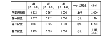
図5に示される表は、計算機シミュレーションにおける伝送信号の諸元である。図6に示される表は、計算機シミュレーションで比較評価を行うアンテナ配置の諸元である。アレーアンテナの開口径は角度分解能をそろえるため、4パターンの配置すべてに共通して1mとする。等間隔配置は、比較対象となる一般的な配列であり、ステアリングベクトルの一次従属を持つ。第一配置から第三配置は、上述した配列構成である。第一配置では、d_2/d_1がルート2(2の1/2乗)になる。第二配置では、d_1が1波長(0.05m)であり、d_2/d_1=10.5である。第三配列では、本シミュレーションでは

に対して、d_2/d_1=43/41となる比で配列している。配列の比較を図7に示す。
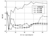
図8はシミュレーション結果である。横軸は遅延波の到来方向、縦軸は所望信号(所望波が示す信号)との平均二乗誤差である。平均二乗誤差が小さいほど不要波による干渉を効果的に除去できていると言える。結果より、等間隔配置では、帯域の最高周波数(30 kHz)において空間エイリアシングが生じる角度(8.7度)以降は干渉波の抑圧性能が低下している。他方で、第一配置~第三配置では、10度以上の到来角で等間隔配置よりも良い性能が達成できており、等化性能が向上していることがわかる。
以上の評価結果より、第一配置~第三配置によって等化性能の向上効果が得られることを示した。
このように、第一配置、第二配置及び第三配置のいずれかが採用されたアンテナ装置10を用いることによって、受信された信号に対する等化処理の精度を向上させることが可能となる。
このように、第一配置、第二配置及び第三配置のいずれかが採用されたアンテナ装置10を用いることによって、受信された信号に対する等化処理の精度を向上させることが可能となる。
特に、広帯域の水中通信では、周波数帯域内で波長の長さが2倍以上異なることがしばしばある。帯域内の波長ごとに空間エイリアシングが生じる到来方向の関係性が異なることから、水中通信では上記の問題がより深刻化し、あらゆる方向からの不要波の除去が難しくなる。このような状況においても、上述したように第一配置、第二配置及び第三配置のいずれかが採用されたアンテナ装置10を用いることによって、受信された信号に対する等化処理の精度を向上させることが可能となる。
以下、アンテナ装置10の変形例について説明する。上述した説明では、いずれもアンテナ装置10におけるアンテナ素子11の配置は一次元的な配置であったが、二次元的にアンテナ素子11が配置されてもよい。この場合、二次元的にビームを走査し、仰角・方位角方向の2つからの干渉波に対して有効に働く。
図9は二次元的な配置の第一具体例を示す図である。図10は二次元的な配置の第二具体例を示す図である。図9では、アンテナ素子11が、第一軸に沿って1列、第二軸に沿って1列、それぞれ配置されている。第一軸と第二軸とは直交している。具体的には、図9ではアンテナ素子11がL字型に配置されている。L字以外にも十字配列や他の二次元配列でもよい。また、第一軸と第二軸とはそれぞれ1列ではなく、複数の列が配置されてもよい。図10では、アンテナ素子11が第一軸及び第二軸に沿って矩形状に配置されている。
図9及び図10の配置例では、配置間隔d_(1,1)からd_(1,N-1)の組が式4の条件を満たさず、且つ、d_(2,1)からd_(2,N-1)の組が式4の条件を満たさない。配置間隔d_(1,1)からd_(1,N-1)の組に関しては、第一配置~第三配置のいずれであってもよい。また、配置間隔d_(2,1)~d_(2,N-1)の組に関しても、第一配置~第三配置のいずれであってもよい。このとき、配置間隔d_(1,1)からd_(1,N-1)の配置パターンと、d_(2,1)からd_(2,N-1)の配置パターンとは、同じであってもよいし、異なっていてもよい。例えば、配置間隔d_(1,1)からd_(1,N-1)の組が第一配置であり、d_(2,1)からd_(2,N-1)の組も第一配置としてそれぞれ構成されてもよい。また、例えば、配置間隔d_(1,1)からd_(1,N-1)の組が第一配置であり、d_(2,1)からd_(2,N-1)の組が第二配置としてそれぞれ構成されてもよい。
また、配置間隔d_(1,1)からd_(1,N-1)の組が式4の条件を満たさず、且つ、d_(2,1)からd_(2,N-1)の組が式4の条件を満たすように構成されてもよい。また、配置間隔d_(1,1)からd_(1,N-1)の組が式4の条件を満たし、且つ、d_(2,1)からd_(2,N-1)の組が式4の条件を満たさないように構成されてもよい。このような構成では、上述した配置間隔d_(1,1)からd_(1,N-1)の組が式4の条件を満たさず、且つ、d_(2,1)からd_(2,N-1)の組も式4の条件を満たさないように構成されたものに比べて性能は低い可能性があるが、少なくとも従来の構成よりは性能を向上させることが可能である。
また、図7のように、二次元上にメッシュグリッドに配列されてもよい。図9や図10に示された配置であれば、二次元方向のいずれの方向にも一次従属な組のステアリングベクトルを持たない。そのため、等化性能を向上させることが可能となる。
図9及び図10の例では、第一軸と第二軸とは直交していたが、必ずしも直交していなくてもよい。
図9及び図10の例では、第一軸と第二軸とは直交していたが、必ずしも直交していなくてもよい。
以上、この発明の実施形態について図面を参照して詳述してきたが、具体的な構成はこの実施形態に限られるものではなく、この発明の要旨を逸脱しない範囲の設計等も含まれる。
本発明は、電波や音波(超音波を含む)を受信する技術に適用することができる。
10…アンテナ装置、11…アンテナ素子,20…受信装置(等化装置)、201…変換部、202…FFフィルター、203…合成器、204…出力推定部、205…フィルター係数取得部
Claims (1)
- 音波又は電波を受信するN個(Nは3以上の整数)のアンテナ素子を備え、
前記アンテナ素子は、ある音波又は電波の入射角度θに対応するステアリングベクトルと、他の音波又は電波の入射角度θ_d(θ_dは-π/2~+π/2)に対応するステアリングベクトルと、が一次従属にならない位置に配置されている、アンテナ装置。
Priority Applications (2)
| Application Number | Priority Date | Filing Date | Title |
|---|---|---|---|
| PCT/JP2022/028803 WO2024023933A1 (ja) | 2022-07-26 | 2022-07-26 | アンテナ装置 |
| JP2024536599A JP7751242B2 (ja) | 2022-07-26 | 2022-07-26 | アンテナ装置および受信システム |
Applications Claiming Priority (1)
| Application Number | Priority Date | Filing Date | Title |
|---|---|---|---|
| PCT/JP2022/028803 WO2024023933A1 (ja) | 2022-07-26 | 2022-07-26 | アンテナ装置 |
Publications (1)
| Publication Number | Publication Date |
|---|---|
| WO2024023933A1 true WO2024023933A1 (ja) | 2024-02-01 |
Family
ID=89705647
Family Applications (1)
| Application Number | Title | Priority Date | Filing Date |
|---|---|---|---|
| PCT/JP2022/028803 Ceased WO2024023933A1 (ja) | 2022-07-26 | 2022-07-26 | アンテナ装置 |
Country Status (2)
| Country | Link |
|---|---|
| JP (1) | JP7751242B2 (ja) |
| WO (1) | WO2024023933A1 (ja) |
Citations (4)
| Publication number | Priority date | Publication date | Assignee | Title |
|---|---|---|---|---|
| WO1999065160A1 (en) * | 1998-06-05 | 1999-12-16 | Siemens Information And Communication Networks Spa | Spatio-temporal equalisation using cholesky factorisation and systolic arrays |
| US6697633B1 (en) * | 1995-06-02 | 2004-02-24 | Northrop Grummar Corporation | Method permitting increased frequency re-use in a communication network, by recovery of transmitted information from multiple cochannel signals |
| JP2007178372A (ja) * | 2005-12-28 | 2007-07-12 | Denso It Laboratory Inc | 到来方位推定装置 |
| JP2017104476A (ja) * | 2015-03-09 | 2017-06-15 | 炭 親良 | ビームフォーミング方法、計測イメージング装置、及び、通信装置 |
-
2022
- 2022-07-26 WO PCT/JP2022/028803 patent/WO2024023933A1/ja not_active Ceased
- 2022-07-26 JP JP2024536599A patent/JP7751242B2/ja active Active
Patent Citations (4)
| Publication number | Priority date | Publication date | Assignee | Title |
|---|---|---|---|---|
| US6697633B1 (en) * | 1995-06-02 | 2004-02-24 | Northrop Grummar Corporation | Method permitting increased frequency re-use in a communication network, by recovery of transmitted information from multiple cochannel signals |
| WO1999065160A1 (en) * | 1998-06-05 | 1999-12-16 | Siemens Information And Communication Networks Spa | Spatio-temporal equalisation using cholesky factorisation and systolic arrays |
| JP2007178372A (ja) * | 2005-12-28 | 2007-07-12 | Denso It Laboratory Inc | 到来方位推定装置 |
| JP2017104476A (ja) * | 2015-03-09 | 2017-06-15 | 炭 親良 | ビームフォーミング方法、計測イメージング装置、及び、通信装置 |
Non-Patent Citations (2)
| Title |
|---|
| BACKES THOMAS D.: "Parameter identifiability in a phased-subarray MIMO radar", 2014 IEEE AEROSPACE CONFERENCE, IEEE, 1 March 2014 (2014-03-01), pages 1 - 6, XP032607306, DOI: 10.1109/AERO.2014.6836507 * |
| KAH-CHYE TAN, KWOK-CHIANG HO, ARYE NEHORAI: "Linear Independence of Steering Vectors of an Electromagnetic Vector Sensor", IEEE TRANSACTIONS ON SIGNAL PROCESSING, IEEE, USA, vol. 44, no. 12, 1 December 1996 (1996-12-01), USA, XP011057648, ISSN: 1053-587X * |
Also Published As
| Publication number | Publication date |
|---|---|
| JPWO2024023933A1 (ja) | 2024-02-01 |
| JP7751242B2 (ja) | 2025-10-08 |
Similar Documents
| Publication | Publication Date | Title |
|---|---|---|
| Sekiguchi et al. | Wideband beamspace adaptive array utilizing FIR fan filters for multibeam forming | |
| US5581495A (en) | Adaptive signal processing array with unconstrained pole-zero rejection of coherent and non-coherent interfering signals | |
| US10243593B2 (en) | Method of combatting interference by spatial filtering or spatio-temporal filtering in a multi-channel receiver | |
| JP2014027653A (ja) | 通信装置、および指向性制御方法 | |
| Pelekanakis et al. | Comparison of sparse adaptive filters for underwater acoustic channel equalization/estimation | |
| Zou et al. | A robust algorithm for linearly constrained adaptive beamforming | |
| CN111537958A (zh) | 一种宽线性降秩最小熵无失真响应的波束形成方法 | |
| JP7751242B2 (ja) | アンテナ装置および受信システム | |
| Liu et al. | Design and analysis of broadband beamspace adaptive arrays | |
| CN116400386A (zh) | 一种基于lcmv准则的零相位偏差stap抗干扰方法及系统 | |
| CN111817765B (zh) | 一种基于频率约束的广义旁瓣对消宽带波束形成方法 | |
| JP5867968B2 (ja) | 無線受信装置及び無線受信方法並びに無線システム | |
| JPH0786972A (ja) | 適応等化器 | |
| KR102795630B1 (ko) | 수신 장치 | |
| El-Keyi et al. | Wideband robust beamforming based on worst-case performance optimization | |
| JP5325624B2 (ja) | マルチアンテナ受信機及びマルチアンテナ受信機を用いた受信方法 | |
| Huang et al. | An efficient subband method for wideband adaptive beamforming | |
| WO2023170968A1 (ja) | 等化方法、等化装置及び受信システム | |
| Hossain et al. | Convolution constrained robust beamforming techniques for broadband microphone array | |
| Zhang et al. | Broadband Beamforming Aided Symbol Detection for Single-Carrier Underwater Acoustic Communications | |
| Yang et al. | Adaptive design of FIR filter with applications in broadband beamforming | |
| Hung et al. | Real time implementation of frost beamformer for underwater communications | |
| JP5337746B2 (ja) | Ofdm信号合成用受信装置及び中継装置 | |
| Fukumoto et al. | Efficient Delay Wave Suppression Using Spatio-Temporal Equalization with Unequally Spaced Array for Underwater Acoustic Communications | |
| Ghavami | An adaptive wideband array using a single real multiplier for each antenna element |
Legal Events
| Date | Code | Title | Description |
|---|---|---|---|
| 121 | Ep: the epo has been informed by wipo that ep was designated in this application |
Ref document number: 22953030 Country of ref document: EP Kind code of ref document: A1 |
|
| DPE1 | Request for preliminary examination filed after expiration of 19th month from priority date (pct application filed from 20040101) | ||
| WWE | Wipo information: entry into national phase |
Ref document number: 2024536599 Country of ref document: JP |
|
| NENP | Non-entry into the national phase |
Ref country code: DE |
|
| 122 | Ep: pct application non-entry in european phase |
Ref document number: 22953030 Country of ref document: EP Kind code of ref document: A1 |