WO2024023868A1 - 体調異常検出装置及び体調異常検出方法 - Google Patents
体調異常検出装置及び体調異常検出方法 Download PDFInfo
- Publication number
- WO2024023868A1 WO2024023868A1 PCT/JP2022/028555 JP2022028555W WO2024023868A1 WO 2024023868 A1 WO2024023868 A1 WO 2024023868A1 JP 2022028555 W JP2022028555 W JP 2022028555W WO 2024023868 A1 WO2024023868 A1 WO 2024023868A1
- Authority
- WO
- WIPO (PCT)
- Prior art keywords
- heart rate
- physical condition
- occupant
- detection device
- abnormality detection
- Prior art date
Links
- 238000001514 detection method Methods 0.000 title claims abstract description 124
- 230000005856 abnormality Effects 0.000 title claims abstract description 92
- 238000004364 calculation method Methods 0.000 claims abstract description 35
- 230000002159 abnormal effect Effects 0.000 claims description 26
- 238000000034 method Methods 0.000 claims description 13
- 206010015037 epilepsy Diseases 0.000 claims description 3
- 238000003384 imaging method Methods 0.000 abstract description 15
- 230000006870 function Effects 0.000 description 15
- 238000010586 diagram Methods 0.000 description 8
- 230000000694 effects Effects 0.000 description 4
- 201000010099 disease Diseases 0.000 description 3
- 208000037265 diseases, disorders, signs and symptoms Diseases 0.000 description 3
- 101000911772 Homo sapiens Hsc70-interacting protein Proteins 0.000 description 2
- 108090000237 interleukin-24 Proteins 0.000 description 2
- 101001139126 Homo sapiens Krueppel-like factor 6 Proteins 0.000 description 1
- 101000710013 Homo sapiens Reversion-inducing cysteine-rich protein with Kazal motifs Proteins 0.000 description 1
- 101000661807 Homo sapiens Suppressor of tumorigenicity 14 protein Proteins 0.000 description 1
- 239000006185 dispersion Substances 0.000 description 1
- 230000003287 optical effect Effects 0.000 description 1
- 239000007787 solid Substances 0.000 description 1
- 230000003068 static effect Effects 0.000 description 1
Images


Classifications
-
- A—HUMAN NECESSITIES
- A61—MEDICAL OR VETERINARY SCIENCE; HYGIENE
- A61B—DIAGNOSIS; SURGERY; IDENTIFICATION
- A61B5/00—Measuring for diagnostic purposes; Identification of persons
- A61B5/02—Detecting, measuring or recording pulse, heart rate, blood pressure or blood flow; Combined pulse/heart-rate/blood pressure determination; Evaluating a cardiovascular condition not otherwise provided for, e.g. using combinations of techniques provided for in this group with electrocardiography or electroauscultation; Heart catheters for measuring blood pressure
- A61B5/024—Detecting, measuring or recording pulse rate or heart rate
- A61B5/0245—Detecting, measuring or recording pulse rate or heart rate by using sensing means generating electric signals, i.e. ECG signals
Definitions
- the present disclosure relates to a physical condition abnormality detection device and a physical condition abnormality detection method.
- the driver physical condition monitor described in Patent Document 1 which is common in terms of vehicle driving safety with the physical condition abnormality detection device according to the present disclosure, detects whether the physical condition of the driver who is driving the vehicle is good or not.
- the driver's physical condition e.g., heart rate, pulse waveform
- a warning is issued to the driver.
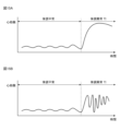
- the heart rate when the physical condition is abnormal is different from that when the physical condition is normal, as shown in Figure 15A.
- the former heart rate may not necessarily be clearly higher than the latter heart rate.
- the above-mentioned driver physical condition monitor detects that the driver driving the above-mentioned vehicle has the latter disease, and that the driver has an abnormal physical condition, that is, a sudden change in physical condition that cannot be predicted in advance. There have been cases where it has not been possible to detect the fact that the driver has experienced an abnormal physical condition, even though it has already occurred.
- An object of the present disclosure is to provide a physical condition abnormality detection device and a physical condition abnormality detection method that can suppress a situation in which it is not possible to detect the fact that a physical condition abnormality has occurred in a passenger on board a vehicle. .
- a physical condition abnormality detection device includes: a photographing section that photographs an image of an occupant riding in a vehicle; a calculating section that calculates the heart rate of the occupant based on the image; a determination unit that determines whether the heart rate is stable; and a correction unit that corrects a heart rate threshold for detecting whether or not the occupant is in an abnormal physical condition based on the heart rate of the occupant based on the determination result. , a detection unit that detects that the occupant is in an abnormal physical condition when the heart rate exceeds the corrected heart rate threshold.
- the physical condition abnormality detection device it is possible to suppress a situation in which it is impossible to detect the fact that a physical condition abnormality has occurred in an occupant riding in a vehicle.
- FIG. 2 is a functional block diagram of the physical condition abnormality detection device TK of the first embodiment.
- the hardware configuration of the physical condition abnormality detection device TK of the first embodiment is shown.
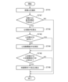
- 3 is a flowchart showing the operation of the physical condition abnormality detection device TK of the first embodiment.
- FIG. 2 is a functional block diagram of a physical condition abnormality detection device TK according to a second embodiment.
- the relationship between occupant JI and normal heart rate SP(T) in Embodiment 2 is shown.
- the relationship between the normal heart rate SP(T) and the weighting coefficient W of the passenger JI in the second embodiment is shown.
- 7 is a flowchart showing the operation of the physical condition abnormality detection device TK according to the second embodiment.
- FIG. 3 is a functional block diagram of a physical condition abnormality detection device TK according to a third embodiment.
- 12 shows the relationship between occupant JI and stable heart rate SP(T) in normal conditions in Embodiment 3.
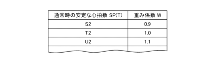
- the relationship between the normal stable heart rate SP(T) and the weighting coefficient W of the occupant JI in Embodiment 3 is shown.
- 12 is a flowchart showing the operation of the physical condition abnormality detection device TK of Embodiment 3.
- FIG. 4 is a functional block diagram of a physical condition abnormality detection device TK according to a fourth embodiment. The relationship between the heart rate SP of the occupant JI and the body movement TD of the occupant JI in Embodiment 4 is shown.
- FIG. 15A shows the relationship (Part 1) between the heart rate when the physical condition is normal and the heart rate when the physical condition is abnormal.
- FIG. 15B shows the relationship (Part 2) between the heart rate when the physical condition is normal and the heart rate when the physical condition is abnormal.
- Embodiment 1 The physical condition abnormality detection device TK of Embodiment 1 will be explained.
- FIG. 1 is a functional block diagram of the physical condition abnormality detection device TK of the first embodiment.
- the functions of the physical condition abnormality detection device TK of the first embodiment will be explained with reference to FIG.
- the physical condition abnormality detection device TK of Embodiment 1 detects whether a physical condition abnormality TI has occurred in the passenger JI (in particular, the passenger JI driving the vehicle SR) boarding the vehicle SR (not shown). As shown in FIG. 1, it includes an imaging section SE, a calculation section SS, a determination section HT, a correction section HS, and a detection section KS.
- the abnormal physical condition TI refers to, for example, a state in which the passenger JI develops epilepsy or the like.
- the imaging unit SE corresponds to the “imaging unit”
- the calculation unit SS corresponds to the “calculation unit”
- the determination unit HT corresponds to the “judgment unit”
- the correction unit HS corresponds to the “correction unit”.
- the detection unit KS corresponds to a “detection unit”.
- the photographing unit SE photographs an image GZ of the passenger JI.
- the imaging unit SE includes an optical camera that captures the image GZ under light, for example, one or more visible light cameras, or one or more cameras using an N-IR light source and a filter that passes only the infrared region. It consists of an infrared camera.
- the calculation unit SS calculates the heart rate SP (here, more precisely, the pulse rate MH (not shown)) of the passenger JI based on the image GZ photographed by the photographing unit SE.
- the calculation unit SS performs the calculation using a conventionally known method, for example, using changes in brightness on the surface of different people's faces depending on differences in the pulse rate MH of the people. Therefore, more specifically, the calculation unit SS detects the face of the passenger JI from the image GZ, and calculates the pulse wave number MH of the passenger JI based on the detected change in brightness on the surface of the face of the passenger JI.
- the calculation unit SS performs the above-described detection using, for example, a classifier based on a general algorithm that combines a Haar-Like detector with Adaboost or Casecade.
- the calculation unit SS may obtain and calculate the pulse wave number MH using, for example, a biological sensor.
- the biosensor is installed, for example, inside the vehicle SR (for example, in the front of the vehicle interior, inside the seat belt, inside the seat), or is worn in the form of a wearable by the occupant JI himself.
- the determination unit HT determines whether the heart rate SP of the occupant JI calculated by the calculation unit SS is stable.
- the determination unit HT performs the above-mentioned determination by, for example, comparing the standard deviation value, variance value, etc. of the heart rate SP in the most recent certain period with a predetermined reference standard deviation value, reference variance value, etc. conduct.
- the correction unit HS corrects the heart rate threshold SPS used by the detection unit KS to detect physical condition abnormality TI. More specifically, the correction unit HS changes the heart rate threshold SPS to the value A by subtracting the initially set correction value (for example, the value B) from the initially set heart rate threshold SPS (for example, the value A). to the value (AB).
- the detection unit KS detects whether or not the passenger JI has an abnormal physical condition TI based on whether or not the heart rate SP of the passenger JI calculated by the calculation unit SS exceeds the heart rate threshold SPS.
- the detection unit KS uses the initially set heart rate threshold SPS (for example, the value A described above) as the heart rate threshold SPS when (1) the heart rate SP of the passenger JI becomes stable; ) When the heart rate SP of the passenger JI is not stable, the heart rate threshold SPS (for example, the value (AB) described above) after being corrected by the correction unit HS is used.
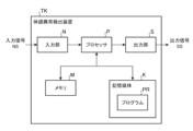
- FIG. 2 shows the hardware configuration of the physical condition abnormality detection device TK of the first embodiment.
- the physical condition abnormality detection device TK of Embodiment 1 includes a processor P, a memory M, and a storage medium K, as shown in FIG. 2, in order to perform the above-mentioned functions. and an output section S.
- the processor P is the core of a well-known computer that operates the hardware according to the software.
- the memory M includes, for example, DRAM (Dynamic Random Access Memory) and SRAM (Static Random Access Memory).
- the storage medium K includes, for example, a hard disk drive (HDD), a solid state drive (SSD), and a ROM (Read Only Memory).
- the storage medium K stores the program PR.
- the program PR is a group of instructions that defines the content of processing that the processor P should execute.
- the input section N and the output section S include, for example, an input interface and an output interface for exchanging input signals NS and output signals SS related to the operation of the processor P with the outside of the physical condition detection device TK. be done.
- the processor P executes the program PR stored in the storage medium K on the hardware. , by using the memory M and controlling the operations of the input section N and output section S as necessary to realize the functions of each section from the imaging section SE to the detection section KS (shown in FIG. 1). do.
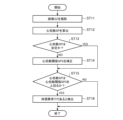
- FIG. 3 is a flowchart showing the operation of the physical condition abnormality detection device TK of the first embodiment.
- the operation of the physical condition abnormality detection device TK of the first embodiment will be explained with reference to the flowchart of FIG. 3.
- Step ST11 Photographing unit SE (illustrated in FIG. 1) photographs an image GZ (illustrated in FIG. 1) of occupant JI (illustrated in FIG. 1) riding in vehicle SR.
- Step ST12 The calculation unit SS (shown in FIG. 1) calculates the heart rate SP of the occupant JI based on the image GZ captured by the imaging unit SE.
- Step ST13 The determination unit HT (shown in FIG. 1) determines whether or not the heart rate SP of the occupant JI is stable, using the heart rate SP of the occupant JI calculated by the calculation unit SS. When it is determined that the heart rate SP of the occupant JI is stable, the process proceeds to step ST15; on the other hand, when it is determined that the heart rate SP of the occupant JI is not stable, the process proceeds to step ST14. Proceed to. Here, since it is determined that the heart rate SP of the passenger JI is not stable under the above assumption, the process proceeds to step ST14.
- Step ST14 The correction unit HS (shown in FIG. 1), for example, corrects the heart rate threshold SPS (shown in FIG. 1), which was initially the value A described above, to ).
- Step ST15 The detection unit KS (shown in FIG. 1) determines that the heart rate SP of the occupant JI calculated by the calculation unit SS is a heart rate threshold SPS, for example, a heart rate threshold SPS after being corrected by the correction unit HS. (For example, the above value (AB)) is determined.
- a heart rate threshold SPS for example, a heart rate threshold SPS after being corrected by the correction unit HS.
- AB the above value
- Step ST16 When the heart rate SP of the occupant JI exceeds the heart rate threshold SPS, the detection unit KS determines that the occupant JI has an abnormal physical condition TI, that is, detects that the occupant JI has an abnormal physical condition TI. do.
- the detection unit KS detects the condition after the heart rate SP of the occupant JI is corrected by the correction unit HS. Based on whether or not the heart rate exceeds the heart rate threshold SPS, it is detected whether or not the passenger JI is experiencing physical condition abnormality TI. As a result, even if the occupant JI is sick and the heart rate SP of the occupant JI is not the heart rate SP illustrated in FIG. 15A but the heart rate SP illustrated in FIG. 15B, the abnormal physical condition TI of the occupant JI ( It is possible to detect whether an abnormal physical condition (as shown in FIG. 15B) is occurring.
- Embodiment 2 The physical condition abnormality detection device TK of Embodiment 2 will be explained.
- the physical condition abnormality detection device TK of Embodiment 2 is different from the physical condition abnormality detection device TK of Embodiment 1 (shown in FIG. ) is used. More specifically, the physical condition abnormality detection device TK of the second embodiment inherently detects, for example, the heart rates SPa, SPb, and SPc (not shown) of the plurality of occupants JIa, JIb, and JIc (not shown). focuses on the differences between each other, and more specifically, for example, there are people whose heart rate SP is relatively high during normal times, and in contrast, there are people whose heart rate SP is relatively low during normal times.
- the physical condition abnormality detection device TK of Embodiment 2 is based on the individual heart rate threshold SPS(K), which is the heart rate threshold SPS for each of the plurality of occupants JIa, JIb, and JIc, that is, the individual heart rate.
- SPS(K) is the heart rate threshold SPS for each of the plurality of occupants JIa, JIb, and JIc, that is, the individual heart rate.
- Number threshold values SPS (Ka), SPS (Kb), and SPS (Kc) are used.
- normal times means, for example, (1) when the occupant JI is not on board the vehicle SR, (2) when the occupant JI is not driving the vehicle SR, (3) when the occupant JI is not driving the vehicle SR. (4) When crew member JI is driving the vehicle SR and crew member JI has no physical condition abnormality. say.
- the individual heart rate threshold SPS (Ka) is used as a standard for detecting whether or not the passenger JIa has an abnormal physical condition TI
- the individual heart rate threshold SPS (Kb) is used as a standard for detecting whether or not the passenger JIa has an abnormal physical condition TI
- the individual heart rate threshold SPS (Kc) is used as a standard for detecting whether abnormal physical condition TI has occurred in the passenger JIc.
- FIG. 4 is a functional block diagram of the physical condition abnormality detection device TK of the second embodiment.
- the functions of the physical condition abnormality detection device TK of the second embodiment will be explained with reference to FIG. 4.
- the physical condition abnormality detection device TK of the second embodiment like the physical condition abnormality detection device TK of the first embodiment (shown in FIG. 1), includes an imaging unit SE, a calculation unit SS, and a determination unit. HT, a correction section HS, and a detection section KS.
- the functions of the imaging unit SE, calculation unit SS, determination unit HT, and detection unit KS in the second embodiment are basically the functions of the imaging unit SE, calculation unit SS, determination unit HT, and detection unit KS in the first embodiment. It is similar to
- the correction unit HS of the second embodiment calculates the value (AB*W) instead of the calculation performed by the correction unit HS of the first embodiment, for example, the calculation of the value (AB).
- FIG. 5 shows the relationship between the occupant JI and the normal heart rate SP(T) in the second embodiment.
- FIG. 6 shows the relationship between the normal heart rate SP(T) and the weighting coefficient W of the passenger JI in the second embodiment.
- the correction unit HS corrects the individual heart rate thresholds SPS(K) of the occupants JIa, JIb, and JIc in accordance with the normal heart rate SP(T) of each of the occupants JIa, JIb, and JIc. do. More specifically, the correction unit HS adjusts the personal heart rate threshold SPS so that the larger the normal heart rate SP(T) of the occupants JIa, JIb, and JIc is, the larger the personal heart rate threshold SPS(K) becomes. (K) is set.
- the normal heart rate SP(T) of the passenger JIc is the value T1 (T1 ⁇ S1 and T1>U1), and as shown in FIG.
- the normal SP(T) of the occupants JIa, JIb, and JIC is, for example, the average value or median value of the heart rate SP of the occupants JIa, JIb, and JIc.
- the correction unit HS determines whether the occupant JI aboard the vehicle SR is an occupant JIa, an occupant JIb, or an occupant JIc by, for example, analyzing an image of the face of the occupant JI captured in the image GZ. To do this.
- the physical condition abnormality detection device TK of the second embodiment has the same hardware configuration as the physical condition abnormality detection device TK of the first embodiment (shown in FIG. 2).
- FIG. 7 is a flowchart showing the operation of the physical condition abnormality detection device TK of the second embodiment.
- the operation of the physical condition abnormality detection device TK of the second embodiment will be explained with reference to the flowchart of FIG. 7.
- Steps ST21 to ST23 Similar to steps ST11 to ST13 of the first embodiment, the photographing unit SE (shown in FIG. 4) photographs the image GZ, and the calculation unit SS (shown in FIG. 4) calculates the heart rate of the passenger JI.
- the determination unit HT (shown in FIG. 4) determines the stability of the heart rate SP of the passenger JI.
- Step ST24 The correction unit HS of the second embodiment (shown in FIG. 4) is different from the correction unit HS of the first embodiment (shown in FIG. 1), and instead of the heart rate threshold SPS of the first embodiment, By analyzing the image GZ of JI, it is recognized that the passenger JI is the passenger JIa. Based on the above recognition, the correction unit HS calculates the personal heart rate threshold SPS (Ka) of the occupant JIa by the correction described above with reference to FIGS. 5 and 6.
- Step ST25 The detection unit KS (shown in FIG. 4) detects the heart rate SP of the occupant JI calculated by the calculation unit SS, that is, the heart rate SP of the occupant JIa after being corrected by the correction unit HS. It is determined whether or not the personal heart rate threshold SPS (Ka) is exceeded. When it is determined that the heart rate SP of the occupant JIa exceeds the individual heart rate threshold SPS (Ka) of the occupant JIa, the process proceeds to step ST26, and on the other hand, the heart rate SP of the occupant JIa exceeds the heart rate threshold of the occupant JIa. When it is determined that the value is lower than SPS(Ka), the process ends.
- SPS personal heart rate threshold
- Step ST26 When the heart rate SP of the occupant JIa exceeds the heart rate threshold SPS (Ka) of the occupant JIa, the detection unit KS determines that an abnormal physical condition TI has occurred in the occupant JIa. Detects abnormal TI.
- the correction unit HS adjusts the normal heart rate SP(T) of the occupants JIa, JIb, and JIc to correspond to the normal heart rate SP(T) of the occupants JIa, JIb, and JIc.
- JIc that is, the individual heart rate thresholds SPS(Ka), SPS(Kb), and SPS(Kc).
- Embodiment 3 The physical condition abnormality detection device TK of Embodiment 3 will be explained.
- the physical condition abnormality detection device TK of the third embodiment is different from the physical condition abnormality detection device TK of the second embodiment (shown in FIG. 4), and instead of using the normal heart rate SP(T), the physical condition abnormality detection device TK of the third embodiment uses the normal physical condition detection device TK.
- the physical condition abnormality detection device TK of the third embodiment uses the normal physical condition detection device TK.
- stable heart rate SP(T) personal heart rate thresholds SPS(Ka), SPS(Kb), and SPS(Kc) of occupants JIa, JIb, and JIc are calculated.
- stable means that the heart rate SP changes relatively little over time, for example.
- FIG. 8 is a functional block diagram of the physical condition abnormality detection device TK according to the third embodiment.
- the functions of the physical condition abnormality detection device TK of Embodiment 3 will be explained with reference to FIG. 8.
- the physical condition abnormality detection device TK of the third embodiment like the physical condition abnormality detection device TK of the second embodiment (shown in FIG. 4), includes an imaging unit SE, a calculation unit SS, and a determination unit. HT, a correction section HS, and a detection section KS.
- the functions of the imaging unit SE, calculation unit SS, determination unit HT, and detection unit KS in the third embodiment are basically the functions of the imaging unit SE, calculation unit SS, determination unit HT, and detection unit KS in the second embodiment. It is similar to
- the correction unit HS of the third embodiment performs the calculation and value (A-B*W) performed by the correction unit HS of the second embodiment
- the correction unit HS of the third embodiment performs the calculation based on the stable heart rate SP (T) at normal times. Based on the following.
- FIG. 9 shows the relationship between the occupant JI and the normal stable heart rate SP(T) in the third embodiment.
- FIG. 10 shows the relationship between the normal stable heart rate SP(T) and the weighting coefficient W of the passenger JI in the third embodiment.
- the correction unit HS of the third embodiment differs from the correction unit HS of the second embodiment in that the correction unit HS of the third embodiment sets the personal heart rate threshold based on the stable heart rate SP(T) in normal times. Calculate SPS(K).
- the normal stable heart rate SP(T) of occupant JIa is the value S2
- the weighting coefficient corresponding to the value S2 is 0.9.
- the correction unit HS corrects the individual heart rate threshold SPS(Ka) of the occupant JIa to be equal to AB*0.9.
- the stable heart rate SP(T) of passenger JIc during normal times is the value T2 (T2 ⁇ S2 and T2>U2), and as shown in FIG.
- the correction unit HS determines whether or not the normal heart rate SP(T) is stable, for example, based on the standard deviation value of the normal heart rate SP(T) of the passenger JI riding in the vehicle SR. , variance, etc., are compared with predetermined reference standard deviation values, reference dispersion values, etc., respectively.
- the physical condition abnormality detection device TK of the third embodiment has the same hardware configuration as the physical condition abnormality detection device TK of the first embodiment (shown in FIG. 2).
- FIG. 11 is a flowchart showing the operation of the physical condition abnormality detection device TK of the third embodiment.
- the operation of the physical condition abnormality detection device TK of Embodiment 3 will be explained with reference to the flowchart of FIG. 11.
- Steps ST31 to ST33 Similar to steps ST21 to ST23 of the second embodiment, the photographing unit SE (shown in FIG. 8) photographs the image GZ, and the calculation unit SS (shown in FIG. 8) calculates the heartbeat of the passenger JI.
- the determination unit HT (shown in FIG. 8) determines the stability of the heart rate SP of the passenger JI.
- Step ST34 Similar to the correction unit HS (shown in FIG. 4) of the second embodiment, the correction unit HS of the third embodiment (shown in FIG. 8) analyzes the image GZ of the passenger JI, thereby determining the image GZ of the passenger JI. recognizes that the person is passenger JIa. Based on the above recognition, the correction unit HS performs the correction described above with reference to FIGS. 9 and 10 in place of the correction described in the second embodiment with reference to FIGS. Calculate heart rate threshold SPS (Ka).
- Step ST35 Similar to the detection unit KS of the second embodiment, the detection unit KS (shown in FIG. 8) determines that the heart rate SP of the occupant JIa calculated by the calculation unit SS, that is, the heart rate SP of the occupant JIa is It is determined whether or not the individual heart rate threshold SPS (Ka) of the occupant JIa after being corrected by the correction unit HS is exceeded. When it is determined that the heart rate SP of the occupant JIa exceeds the personal heart rate threshold SPS (Ka) of the occupant JIa, the process proceeds to step ST36, and on the other hand, the heart rate SP of the occupant JIa exceeds the heart rate threshold of the occupant JIa. When it is determined that the value is lower than SPS(Ka), the process ends.
- Step ST36 Similar to the detection unit KS of the second embodiment, when the heart rate SP of the occupant JIa exceeds the personal heart rate threshold SPS (Ka) of the occupant JIa, the detection unit KS detects that abnormal physical condition TI occurs in the occupant JIa. In other words, it is determined that the passenger JIa is in an abnormal physical condition TI.
- SPS personal heart rate threshold
- the correction unit HS calculates the personal heart rate threshold SPS (K) of the occupants JIa, JIb, and JIc, that is, the personal heart rate threshold SPS (Ka) , SPS(Kb), and SPS(Kc) are calculated based on the stable heart rate SP(T) during normal times instead of calculating based on the normal heart rate SP(T) in the second embodiment.
- This makes it possible to set individual heart rate thresholds SPS (Ka), SPS (Kb), and SPS (Kc) for occupants JIa, JIb, and JIc with higher precision.
- Embodiment 4 The physical condition abnormality detection device TK of Embodiment 4 will be explained.
- the physical condition abnormality detection device TK of Embodiment 4 differs from the physical condition abnormality detection device TK of Embodiments 1 to 3 (shown in FIGS. 1, 4, and 8) in that the heart rate threshold SPS is adjusted by the correction unit HS.
- the correction (step ST14 of the first embodiment, step ST24 of the second embodiment, and step ST34 of the third embodiment) is applied to the body movement of the occupant JI riding the vehicle SR (in particular, the occupant JI driving the vehicle SR). This is done taking into consideration whether TD has occurred or not.
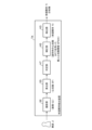
- FIG. 12 is a functional block diagram of the physical condition abnormality detection device TK according to the fourth embodiment.
- the functions of the physical condition abnormality detection device TK of Embodiment 4 will be explained with reference to FIG. 12.
- the physical condition abnormality detection device TK of the fourth embodiment like the physical condition abnormality detection device TK of the first embodiment (shown in FIG. 1), includes an imaging unit SE, a calculation unit SS, and a determination unit. HT, a correction section HS, and a detection section KS.
- the physical condition abnormality detection device TK of Embodiment 4 is different from the physical condition abnormality detection device TK of Embodiment 1, and further includes a detection section KC.
- the detection unit KC corresponds to a “detection unit”.
- the detection unit KC determines whether a body movement TD occurs in an occupant JI riding in the vehicle SR or driving the vehicle SR, and detects whether the body movement TD of the occupant JI corresponds to a predetermined reference body movement. Detects whether or not it is below.
- the detection unit KC performs the detection by calculating the amount of movement of the occupant JI based on the skeleton of the occupant JI using, for example, a conventionally known general algorithm (for example, OpenPose).
- FIG. 13 shows the relationship between the heart rate SP of the occupant JI and the body movement TD of the occupant JI in the fourth embodiment.
- the heart rate SP of the occupant JI is determined by the body movement TD occurring in the occupant JI riding in the vehicle SR, for example, due to the vehicle SR traveling on a rough road.
- the occupant JI is shaking, that is, when the occupant JI is shaking, it is disturbed, unlike when the occupant JI is not shaking.
- the physical condition abnormality detection device TK of the fourth embodiment has the same hardware configuration as the physical condition abnormality detection device TK of the first embodiment (shown in FIG. 2).
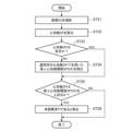
- FIG. 14 is a flowchart showing the operation of the physical condition abnormality detection device TK of the fourth embodiment. The operation of the physical condition abnormality detection device TK of the fourth embodiment will be described below with reference to the flowchart of FIG. 14.
- Steps ST41 to S46 Similar to steps ST11 to ST16 of the first embodiment, steps ST21 to ST26 of the second embodiment, and steps ST31 to ST36 of the third embodiment, images of the occupant JI are taken by the photographing section SE (shown in FIG. 12).
- GZ imaging-detection unit KS (shown in FIG. 12) detects physical condition abnormality TI.
- Step ST47 The detection unit KC (shown in FIG. 12) determines whether body movement TD is occurring in the passenger JI who is riding in the vehicle SR or driving the vehicle SR. It is detected whether TD is lower than the above reference body movement.
- the process proceeds to end.
- the process proceeds to step ST42, and the operations of steps ST42 to ST46 are subsequently performed in the same manner as in the first to third embodiments.
- the detection unit KC determines whether or not body movement TD is occurring in the occupant JI riding in the vehicle SR, and whether or not the body movement TD of the occupant JI is occurring. It is detected whether the body movement is below the standard body movement. Only when it is detected that the body movement TD of the occupant JI is less than the reference body movement, the subsequent processing (processing of steps ST42 to ST46) is performed. As a result, unlike the heart rate SP of Embodiments 1 to 3, the detection unit KS detects whether or not the occupant JI is in abnormal physical condition TI without being influenced by the body movement TD of the occupant JI. This can be done based on the heart rate SP of the passenger JI.
- the physical condition abnormality detection device can be used to suppress a situation in which it is impossible to detect the fact that an occupant riding in a vehicle has a physical condition abnormality.
- GZ image GZ image, HS correction unit, HT judgment unit, JI passenger, K storage medium, KC detection unit, KS detection unit, SE imaging unit, SP heart rate, SPS heart rate threshold, SS calculation unit, TD body movement, TI physical condition abnormality , TK Physical condition abnormality detection device.
Abstract
体調異常検出装置(TK)は、車両に搭乗している乗員(JI)の画像(GZ)を撮影する撮影部(SE)と、前記画像(GZ)に基づき、前記乗員(JI)の心拍数(SP)を算出する算出部(SS)と、前記心拍数(SP)が安定しているか否かを判定する判定部(HT)と、前記判定の結果に基づき、前記乗員(JI)が体調異常(TI)であるか否かを前記乗員(JI)の心拍数(SP)に基づき検出するための心拍数閾値(SPS)を補正する補正部(HS)と、前記心拍数(SP)が前記補正された心拍数閾値(SPS)を上回るとき、前記乗員(JI)が体調異常(TI)であると検出する検出部(KS)と、を含む。
Description
本開示は、体調異常検出装置及び体調異常検出方法に関する。
本開示に係る体調異常検出装置と車両運転の安全性の点で共通する、特許文献1に記載のドライバ体調モニタは、車両を運転中のドライバの体調の良否を検出すべく、車両を運転しているときのドライバの身体状態(例えば、心拍数、脈波形)が、停車しているときのドライバの身体状態から一定範囲内にないとき、ドライバに警報を出す。
しかしながら、例えば、疾患の種類の如何(例えば、てんかん)によっては、図15Aに示されるように、殆どの疾患者の場合、体調が異常であるときの心拍数が、体調が平常であるときの心拍数よりも、明らかに高くなるものの、図15Bに示されるように、一部の疾患者の場合、前者の心拍数が、後者の心拍数よりも、明らかに高くなるとは限らないことがある。これにより、上記したドライバ体調モニタは、上記した車両を運転しているドライバが後者の疾患者であり、かつ、前記ドライバに体調異常、即ち、事前に予測することができない体調の急激な変化が発生しているに拘わらず、前記ドライバに前記体調異常が発生した事実を検出することができないことがあった。
本開示の目的は、車両に搭乗している乗員に体調異常が発生している事実を検出することができない事態を抑制することができる体調異常検出装置及び体調異常検出方法を提供することにある。
上記した課題を解決すべく、本開示に係る体調異常検出装置は、車両に搭乗している乗員の画像を撮影する撮影部と、画像に基づき、乗員の心拍数を算出する算出部と、心拍数が安定しているか否かを判定する判定部と、判定の結果に基づき、乗員が体調異常であるか否かを乗員の心拍数に基づき検出するための心拍数閾値を補正する補正部と、心拍数が補正された心拍数閾値を上回るとき、乗員が体調異常であると検出する検出部と、を含む。
本開示に係る体調異常検出装置によれば、車両に搭乗している乗員に体調異常が発生している事実を検出することができない事態を抑制することができる。
本開示に係る体調異常検出装置の実施形態について説明する。
実施形態1.
〈実施形態1〉
実施形態1の体調異常検出装置TKについて説明する。
〈実施形態1〉
実施形態1の体調異常検出装置TKについて説明する。
〈実施形態1の機能〉
図1は、実施形態1の体調異常検出装置TKの機能ブロック図である。以下、実施形態1の体調異常検出装置TKの機能について、図1を参照して説明する。
図1は、実施形態1の体調異常検出装置TKの機能ブロック図である。以下、実施形態1の体調異常検出装置TKの機能について、図1を参照して説明する。
以下では、「心拍数」は、「脈拍数」を含むことを想定する。
実施形態1の体調異常検出装置TKは、車両SR(図示せず。)に搭乗している乗員JI(特に、車両SRを運転している乗員JI)に、体調異常TIが発生しているか否かを検出すべく、図1に示されるように、撮影部SEと、算出部SSと、判定部HTと、補正部HSと、検出部KSと、を含む。
体調異常TIとは、例えば、乗員JIがてんかん等を発症している状態をいう。
撮影部SEは、「撮影部」に対応し、算出部SSは、「算出部」に対応し、判定部HTは、「判定部」に対応し、補正部HSは、「補正部」に対応し、検出部KSは、「検出部」に対応する。
撮影部SEは、乗員JIの画像GZを撮影する。撮影部SEは、光の下で画像GZを取得する光学カメラ、例えば、1台又は複数台の可視光カメラ、又はN-IR光源及び赤外領域のみを通すフィルタを用いた1台又は複数台の赤外線カメラにより構成される。
算出部SSは、撮影部SEにより撮影された画像GZに基づき、乗員JIの心拍数SP(ここでは、より正確には、脈拍数MH(図示せず。))を算出する。算出部SSは、前記算出を、従来知られた方法により、例えば、人の脈拍数MHの違いに応じて異なる人の顔の表面における輝度の変化を用いる。従って、算出部SSは、より具体的には、画像GZから乗員JIの顔を検出し、検出された乗員JIの顔の表面における輝度の変化に基づき、乗員JIの脈波数MHを算出する。
算出部SSは、上記した検出を、例えば、Haar-Like検出器にAdaboost又はCasecadeを組み合わせた一般的なアルゴリズムによる識別器を用いて行う。
算出部SSは、上記した脈波数MHを、画像GZに基づき算出することに代えて、例えば、生体センサを用いて取得し、算出してもよい。生体センサは、例えば、車両SRの内部(例えば、車室内の前方、シートベルトの内部、座席シートの内部)に設置され、又は、乗員JI自身によりウエアラブルの形態で装着される。
判定部HTは、算出部SSにより算出された乗員JIの心拍数SPが安定しているか否かを判定する。判定部HTは、上記した判定を、例えば、直近の一定期間における心拍数SPの標準偏差値、分散値等を、それぞれ、予め定められた基準標準偏差値、基準分散値等と比較することにより行う。
補正部HSは、判定部HTにより、乗員JIの心拍数SPが不安定であると判定されたとき、検出部KSによる体調異常TIの検出のために用いられる心拍数閾値SPSを補正する。補正部HSは、より詳しくは、初期設定された心拍数閾値SPS(例えば、値A)から初期設定された補正用値(例えば、値B)を減算することにより、心拍数閾値SPSを値Aから値(A-B)へ減少させる。
検出部KSは、算出部SSにより算出された乗員JIの心拍数SPが、心拍数閾値SPSを上回るか否かに基づき、乗員JIに体調異常TIが生じているか否かを検出する。検出部KSは、心拍数閾値SPSとして、(1)乗員JIの心拍数SPが安定するとき、初期設定されている心拍数閾値SPS(例えば、上記した値A)を用い、他方で、(2)乗員JIの心拍数SPが安定してないとき、補正部HSにより補正された後の心拍数閾値SPS(例えば、上記した値(A-B))を用いる。
〈実施形態1のハードウェア構成〉
図2は、実施形態1の体調異常検出装置TKのハードウェア構成を示す。
図2は、実施形態1の体調異常検出装置TKのハードウェア構成を示す。
実施形態1の体調異常検出装置TKは、上述した機能を果たすべく、図2に示されるように、プロセッサPと、メモリMと、記憶媒体Kと、を含み、必要に応じて、入力部Nと、出力部Sと、更に含む。
プロセッサPは、ソフトウェアに従ってハードウェアを動作させる、よく知られたコンピュータの中核である。メモリMは、例えば、DRAM(Dynamic Random Access Memory)、SRAM(Static Random Access Memory)から構成される。記憶媒体Kは、例えば、ハードディスクドライブ(HDD:Hard Disk Drive)、ソリッドステートドライブ(SSD:Solid State Drive)、ROM(Read Only Memory)から構成される。記憶媒体Kは、プログラムPRを記憶する。プログラムPRは、プロセッサPが実行すべき処理の内容を規定する命令群である。
入力部N及び出力部Sは、例えば、体調異常検出装置TKの外部との間でプロセッサPの動作に関連する入力信号NS及び出力信号SSをやりとりするための入力用インターフェイス及び出力用インターフェイスから構成される。
体調異常検出装置TKにおける機能(図1に図示。)とハードウェア構成(図2に図示。)との関係については、ハードウェア上で、プロセッサPが、記憶媒体Kに記憶されたプログラムPRを、メモリMを用いて実行すると共に、必要に応じて、入力部N及び出力部Sの動作を制御することにより、撮影部SE~検出部KS(図1に図示。)の各部の機能を実現する。
〈実施形態1の動作〉
図3は、実施形態1の体調異常検出装置TKの動作を示すフローチャートである。以下、実施形態1の体調異常検出装置TKの動作について、図3のフローチャートを参照して説明する。
図3は、実施形態1の体調異常検出装置TKの動作を示すフローチャートである。以下、実施形態1の体調異常検出装置TKの動作について、図3のフローチャートを参照して説明する。
以下では、説明及び理解を容易にすべく、車両SRの乗員JIの心拍数SPが安定していないことを想定する。
ステップST11:撮影部SE(図1に図示。)は、車両SRに搭乗している乗員JI(図1に図示。)の画像GZ(図1に図示。)を撮影する。
ステップST12:算出部SS(図1に図示。)は、撮影部SEにより撮影された画像GZに基づき、乗員JIの心拍数SPを算出する。
ステップST13:判定部HT(図1に図示。)は、算出部SSにより算出された乗員JIの心拍数SPを用いて、乗員JIの心拍数SPが安定しているか否かを判定する。乗員JIの心拍数SPが安定していると判定されるとき、処理は、ステップST15へ進み、他方で、乗員JIの心拍数SPが安定していないと判定されるとき、処理は、ステップST14へ進む。ここでは、上記した想定の下で、乗員JIの心拍数SPが安定していないと判定されることから、処理はステップST14へ進む。
ステップST14:補正部HS(図1に図示。)は、例えば、当初、上記した値Aであった心拍数閾値SPS(図1に図示。)を補正することにより、上記した値(A-B)へ減少させる。
ステップST15:検出部KS(図1に図示。)は、算出部SSにより算出された乗員JIの心拍数SPが、心拍数閾値SPS、例えば、補正部HSにより補正された後の心拍数閾値SPS(例えば、上記した値(A-B))を上回るか否かを判断する。乗員JIの心拍数SPが心拍数閾値SPSを上回ると判断されるとき、処理は、ステップST16へ進み、他方で、乗員JIの心拍数SPが心拍数閾値SPSを下回ると判断されるとき、処理は、終了する。
ステップST16:検出部KSは、乗員JIの心拍数SPが心拍数閾値SPSを上回るとき、乗員JIに体調異常TIが発生していると判断し、即ち、乗員JIが体調異常TIであると検出する。
〈実施形態1の効果〉
上述したように、実施形態1の体調異常検出装置TKでは、検出部KSは、乗員JIの心拍数SPが安定していない場合、乗員JIの心拍数SPが、補正部HSにより補正された後の心拍数閾値SPSを上回るか否かに基づき、乗員JIに体調異常TIが発生しているか否かを検出する。これにより、乗員JIが疾患者であり、乗員JIの心拍数SPが、図15Aに図示の心拍数SPでなく、図15Bに図示の心拍数SPであっても、乗員JIの体調異常TI(図15Bに図示の体調異常)が発生しているか否かを検出することができる。
上述したように、実施形態1の体調異常検出装置TKでは、検出部KSは、乗員JIの心拍数SPが安定していない場合、乗員JIの心拍数SPが、補正部HSにより補正された後の心拍数閾値SPSを上回るか否かに基づき、乗員JIに体調異常TIが発生しているか否かを検出する。これにより、乗員JIが疾患者であり、乗員JIの心拍数SPが、図15Aに図示の心拍数SPでなく、図15Bに図示の心拍数SPであっても、乗員JIの体調異常TI(図15Bに図示の体調異常)が発生しているか否かを検出することができる。
実施形態2.
〈実施形態2〉
実施形態2の体調異常検出装置TKについて説明する。
〈実施形態2〉
実施形態2の体調異常検出装置TKについて説明する。
実施形態2の体調異常検出装置TKは、実施形態1の体調異常検出装置TK(図1に図示。)と相違し、1つの心拍数閾値SPSに代えて、複数の個人心拍数閾値SPS(K)を用いる。実施形態2の体調異常検出装置TKは、より詳しくは、例えば、複数の乗員JIa、JIb、JIc(図示せず。)の心拍数SPa、SPb、SPc(図示せず。)が、本来的には、相互間で相違することに着目し、より具体的には、例えば、通常時における心拍数SPが比較的高い人が存在し、対照的に、通常時における心拍数SPが比較的低い人が存在することに着目する。実施形態2の体調異常検出装置TKは、前記した着目の上で、複数の乗員JIa、JIb、JIcの各人毎の心拍数閾値SPSである個人心拍数閾値SPS(K)、即ち、個人心拍数閾値SPS(Ka)、SPS(Kb)、SPS(Kc)を用いる。
ここで、「通常時」とは、例えば、(1)乗員JIが車両SRに搭乗していないとき、(2)乗員JIが車両SRを運転していないとき、(3)乗員JIが車両SRに搭乗している場合であって乗員JIに体調異常が発生していないとき、(4)乗員JIが車両SRを運転している場合であって乗員JIに体調異常が発生していないときをいう。
個人心拍数閾値SPS(Ka)は、乗員JIaに体調異常TIが発生しているか否かを検出するための基準に用いられ、個人心拍数閾値SPS(Kb)は、乗員JIbに体調異常TIが発生しているか否かを検出するための基準に用いられ、個人心拍数閾値SPS(Kc)は、乗員JIcに体調異常TIが発生しているか否かを検出するための基準に用いられる。
〈実施形態2の機能〉
図4は、実施形態2の体調異常検出装置TKの機能ブロック図である。以下、実施形態2の体調異常検出装置TKの機能について、図4を参照して説明する。
図4は、実施形態2の体調異常検出装置TKの機能ブロック図である。以下、実施形態2の体調異常検出装置TKの機能について、図4を参照して説明する。
実施形態2の体調異常検出装置TKは、図4に示されるように、実施形態1の体調異常検出装置TK(図1に図示。)と同様に、撮影部SEと、算出部SSと、判定部HTと、補正部HSと、検出部KSと、を含む。
実施形態2の撮影部SE、算出部SS、判定部HT、及び検出部KSの機能は、基本的に、実施形態1の撮影部SE、算出部SS、判定部HT、及び検出部KSの機能と同様である。
実施形態2の補正部HSは、実施形態1の補正部HSによる計算、例えば、値(A-B)の算出に代えて、値(A-B*W)の算出を行う。
図5は、実施形態2の乗員JIと通常時の心拍数SP(T)との関係を示す。
図6は、実施形態2の乗員JIの通常時の心拍数SP(T)と重み係数Wとの関係を示す。
補正部HSは、乗員JIa、JIb、JIcのそれぞれの通常時の心拍数SP(T)の大きさに対応させて、乗員JIa、JIb、JIcのそれぞれの個人心拍数閾値SPS(K)を補正する。補正部HSは、より詳しくは、乗員JIa、JIb、JIcの通常時の心拍数SP(T)がより大きいほど、個人心拍数閾値SPS(K)がより大きくなるように、個人心拍数閾値SPS(K)を設定する。
例えば、図5に示されるように、乗員JIaの通常時の心拍数SP(T)が値S1であり、図6に示されるように、値S1に対応する重み係数が0.9であるとき、補正部HSは、乗員JIaの個人心拍数閾値SPS(Ka)=A-B*0.9であると補正する。
例えば、図5に示されるように、乗員JIbの通常時の心拍数SP(T)が値U1(U1<S1)であり、図6に示されるように、値U1に対応する重み係数が1.1であるとき、補正部HSは、乗員JIbの個人心拍数閾値SPS(Kb)=A-B*1.1であると補正する。
例えば、図5に示されるように、乗員JIcの通常時の心拍数SP(T)が値T1(T1<S1かつT1>U1)であり、図6に示されるように、値T1に対応する重み係数が1.0であるとき、補正部HSは、個人心拍数閾値SPS(Kc)=A-B*1.0であると補正する。
乗員JIa、JIb、JICの通常時のSP(T)は、乗員JIa、JIb、JIcの心拍数SPの、例えば、平均値、中央値である。
補正部HSは、車両SRに搭乗している乗員JIが、乗員JIa、乗員JIb、乗員JIcのいずれであるかの判断を、例えば、画像GZに撮影された乗員JIの顔の画像を分析することにより行う。
〈実施形態2のハードウェア構成〉
実施形態2の体調異常検出装置TKは、実施形態1の体調異常検出装置TKと同様なハードウェア構成(図2に図示。)を有する。
実施形態2の体調異常検出装置TKは、実施形態1の体調異常検出装置TKと同様なハードウェア構成(図2に図示。)を有する。
〈実施形態2の動作〉
図7は、実施形態2の体調異常検出装置TKの動作を示すフローチャートである。以下、実施形態2の体調異常検出装置TKの動作について、図7のフローチャートを参照して説明する。
図7は、実施形態2の体調異常検出装置TKの動作を示すフローチャートである。以下、実施形態2の体調異常検出装置TKの動作について、図7のフローチャートを参照して説明する。
以下では、説明及び理解を容易にすべく、車両SRに搭乗している乗員JIが乗員JIaであることを想定する。
ステップST21~ST23:実施形態1のステップST11~ST13と同様に、撮影部SE(図4に図示。)が画像GZを撮影し、算出部SS(図4に図示。)が乗員JIの心拍数SPを算出し、判定部HT(図4に図示。)が乗員JIの心拍数SPの安定性を判定する。
ステップST24:実施形態2の補正部HS(図4に図示。)は、実施形態1の補正部HS(図1に図示。)と相違し、実施形態1の心拍数閾値SPSに代えて、乗員JIの画像GZを分析することにより、乗員JIが乗員JIaであることを認識する。補正部HSは、前記した認識の下で、図5、図6を参照して上述した補正により、乗員JIaの個人心拍数閾値SPS(Ka)を算出する。
ステップST25:検出部KS(図4に図示。)は、算出部SSにより算出された乗員JIの心拍数SP、即ち、乗員JIaの心拍数SPが、補正部HSにより補正された後の乗員JIaの個人心拍数閾値SPS(Ka)を上回るか否かを判断する。乗員JIaの心拍数SPが乗員JIaの個人心拍数閾値SPS(Ka)を上回ると判断されるとき、処理は、ステップST26へ進み、他方で、乗員JIaの心拍数SPが乗員JIaの心拍数閾値SPS(Ka)を下回ると判断されるとき、処理は、終了する。
ステップST26:検出部KSは、乗員JIaの心拍数SPが乗員JIaの心拍数閾値SPS(Ka)を上回るとき、乗員JIaに体調異常TIが発生していると判断し、即ち、乗員JIaが体調異常TIであると検出する。
〈実施形態2の効果〉
上述したように、実施形態2の体調異常検出装置TKでは、補正部HSが、乗員JIa、JIb、JIcのそれぞれの通常の心拍数SP(T)の大きさに対応させて、乗員JIa、JIb、JIcのそれぞれの個人心拍数閾値SPS(K)、即ち、個人心拍数閾値SPS(Ka)、SPS(Kb)、SPS(Kc)を補正する。これにより、乗員JIに体調異常TIが発生しているか否かを検出することを、乗員JIa、JIb、JIcのそれぞれの通常時の心拍数SP(T)が高いか低いかという個人差を考慮した上で行うことができる。
上述したように、実施形態2の体調異常検出装置TKでは、補正部HSが、乗員JIa、JIb、JIcのそれぞれの通常の心拍数SP(T)の大きさに対応させて、乗員JIa、JIb、JIcのそれぞれの個人心拍数閾値SPS(K)、即ち、個人心拍数閾値SPS(Ka)、SPS(Kb)、SPS(Kc)を補正する。これにより、乗員JIに体調異常TIが発生しているか否かを検出することを、乗員JIa、JIb、JIcのそれぞれの通常時の心拍数SP(T)が高いか低いかという個人差を考慮した上で行うことができる。
実施形態3.
〈実施形態3〉
実施形態3の体調異常検出装置TKについて説明する。
〈実施形態3〉
実施形態3の体調異常検出装置TKについて説明する。
実施形態3の体調異常検出装置TKは、実施形態2の体調異常検出装置TK(図4に図示。)と相違し、通常時の心拍数SP(T)を用いることに代えて、通常時の安定な心拍数SP(T)を用いて、乗員JIa、JIb、JIcの個人心拍数閾値SPS(Ka)、SPS(Kb)、SPS(Kc)を算出する。
ここで、「安定」とは、心拍数SPが、例えば、時系列上での変化が相対的に乏しいことをいう。
〈実施形態3の機能〉
図8は、実施形態3の体調異常検出装置TKの機能ブロック図である。以下、実施形態3の体調異常検出装置TKの機能について、図8を参照して説明する。
図8は、実施形態3の体調異常検出装置TKの機能ブロック図である。以下、実施形態3の体調異常検出装置TKの機能について、図8を参照して説明する。
実施形態3の体調異常検出装置TKは、図8に示されるように、実施形態2の体調異常検出装置TK(図4に図示。)と同様に、撮影部SEと、算出部SSと、判定部HTと、補正部HSと、検出部KSと、を含む。
実施形態3の撮影部SE、算出部SS、判定部HT、及び検出部KSの機能は、基本的に、実施形態2の撮影部SE、算出部SS、判定部HT、及び検出部KSの機能と同様である。
実施形態3の補正部HSは、実施形態2の補正部HSによる計算、値(A-B*W)の算出を行うものの、当該算出を、上記した通常時の安定な心拍数SP(T)に基づき行う。
図9は、実施形態3の乗員JIと通常時の安定な心拍数SP(T)との関係を示す。
図10は、実施形態3の乗員JIの通常時の安定な心拍数SP(T)と重み係数Wとの関係を示す。
実施形態3の補正部HSは、図9、図10に示されるように、実施形態2の補正部HSと相違し、通常時の安定な心拍数SP(T)を基準に、個人心拍数閾値SPS(K)を算出する。
例えば、図9に示されるように、乗員JIaの通常時の安定な心拍数SP(T)が値S2であり、図10に示されるように、値S2に対応する重み係数が0.9であるとき、補正部HSは、乗員JIaの個人心拍数閾値SPS(Ka)=A-B*0.9であると補正する。
例えば、図9に示されるように、乗員JIbの通常時の安定な心拍数SP(T)が値U2(U2<S2)であり、図10に示されるように、値U2に対応する重み係数が1.1であるとき、補正部HSは、乗員JIbの個人心拍数閾値SPS(Kb)=A-B*1.1であると補正する。
例えば、図9に示されるように、乗員JIcの通常時の安定な心拍数SP(T)が値T2(T2<S2かつT2>U2)であり、図10に示されるように、値T2に対応する重み係数が1.0であるとき、補正部HSは、乗員JIcの個人心拍数閾値SPS(Kc)=A-B*1.0であると補正する。
補正部HSは、通常時の心拍数SP(T)が安定であるか否かの判断を、例えば、車両SRに搭乗している乗員JIの通常時の心拍数SP(T)の標準偏差値、分散等を、それぞれ、予め定められた基準標準偏差値、基準分散値等と比較することにより行う。
〈実施形態3のハードウェア構成〉
実施形態3の体調異常検出装置TKは、実施形態1の体調異常検出装置TKと同様なハードウェア構成(図2に図示。)を有する。
実施形態3の体調異常検出装置TKは、実施形態1の体調異常検出装置TKと同様なハードウェア構成(図2に図示。)を有する。
〈実施形態3の動作〉
図11は、実施形態3の体調異常検出装置TKの動作を示すフローチャートである。以下、実施形態3の体調異常検出装置TKの動作について、図11のフローチャートを参照して説明する。
図11は、実施形態3の体調異常検出装置TKの動作を示すフローチャートである。以下、実施形態3の体調異常検出装置TKの動作について、図11のフローチャートを参照して説明する。
以下では、説明及び理解を容易にすべく、車両SRに搭乗している乗員JIが乗員JIaであることを想定する。
ステップST31~ステップST33:実施形態2のステップST21~ST23と同様に、撮影部SE(図8に図示。)が画像GZを撮影し、算出部SS(図8に図示。)が乗員JIの心拍数SPを算出し、判定部HT(図8に図示。)が乗員JIの心拍数SPの安定性を判定する。
ステップST34:実施形態3の補正部HS(図8に図示。)は、実施形態2の補正部HS(図4に図示。)と同様に、乗員JIの画像GZを分析することにより、乗員JIが乗員JIaであることを認識する。補正部HSは、前記した認識の下で、実施形態2で図5、図6を参照して説明した補正に代えて、図9、図10を参照して上述した補正により、乗員JIaの個人心拍数閾値SPS(Ka)を算出する。
ステップST35:検出部KS(図8に図示。)は、実施形態2の検出部KSと同様に、算出部SSにより算出された乗員JIaの心拍数SP、即ち、乗員JIaの心拍数SPが、補正部HSにより補正された後の乗員JIaの個人心拍数閾値SPS(Ka)を上回るか否かを判断する。乗員JIaの心拍数SPが乗員JIaの個人心拍数閾値SPS(Ka)を上回ると判断されるとき、処理は、ステップST36へ進み、他方で、乗員JIaの心拍数SPが乗員JIaの心拍数閾値SPS(Ka)を下回ると判断されるとき、処理は、終了する。
ステップST36:検出部KSは、実施形態2の検出部KSと同様に、乗員JIaの心拍数SPが乗員JIaの個人心拍数閾値SPS(Ka)を上回るとき、乗員JIaに体調異常TIが発生していると判断し、即ち、乗員JIaが体調異常TIであると検出する。
〈実施形態3の効果〉
上述したように、実施形態3の体調異常検出装置TKでは、補正部HSが、乗員JIa、JIb、JIcの個人心拍数閾値SPS(K)の算出を、即ち、個人心拍数閾値SPS(Ka)、SPS(Kb)、SPS(Kc)の算出を、実施形態2における通常時の心拍数SP(T)に基づき行うことに代えて、通常時の安定な心拍数SP(T)に基づき行う。これにより、乗員JIa、JIb、JIcの個人心拍数閾値SPS(Ka)、SPS(Kb)、SPS(Kc)をより高精度に設定することが可能となる。
上述したように、実施形態3の体調異常検出装置TKでは、補正部HSが、乗員JIa、JIb、JIcの個人心拍数閾値SPS(K)の算出を、即ち、個人心拍数閾値SPS(Ka)、SPS(Kb)、SPS(Kc)の算出を、実施形態2における通常時の心拍数SP(T)に基づき行うことに代えて、通常時の安定な心拍数SP(T)に基づき行う。これにより、乗員JIa、JIb、JIcの個人心拍数閾値SPS(Ka)、SPS(Kb)、SPS(Kc)をより高精度に設定することが可能となる。
実施形態4.
〈実施形態4〉
実施形態4の体調異常検出装置TKについて説明する。
〈実施形態4〉
実施形態4の体調異常検出装置TKについて説明する。
実施形態4の体調異常検出装置TKは、実施形態1~実施形態3の体調異常検出装置TK(図1、図4、図8に図示。)と相違し、補正部HSによる心拍数閾値SPSの補正(実施形態1のステップST14、実施形態2のステップST24、実施形態3のステップST34)を、車両SRに搭乗している乗員JI(特に、車両SRを運転している乗員JI)に体動TDが生じているか否かを考慮して行う。
〈実施形態4の機能とハードウェア構成〉
図12は、実施形態4の体調異常検出装置TKの機能ブロック図である。以下、実施形態4の体調異常検出装置TKの機能について、図12を参照して説明する。
図12は、実施形態4の体調異常検出装置TKの機能ブロック図である。以下、実施形態4の体調異常検出装置TKの機能について、図12を参照して説明する。
実施形態4の体調異常検出装置TKは、図12に示されるように、実施形態1の体調異常検出装置TK(図1に図示。)と同様に、撮影部SEと、算出部SSと、判定部HTと、補正部HSと、検出部KSと、を含む。
実施形態4の体調異常検出装置TKは、図12に示されるように、実施形態1の体調異常検出装置TKと相違し、検知部KCを更に含む。
検知部KCは、「検知部」に対応する。
検知部KCは、車両SRに搭乗している、または、車両SRを運転している乗員JIに体動TDが生じているか否か、乗員JIの体動TDが予め定められた基準体動を下回るか否かを検知する。検知部KCは、前記検知を、例えば、従来知られた一般的なアルゴリズム(例えば、OpenPose)を用い、乗員JIの骨格に基づき、乗員JIの動きの量を算出することにより行う。
図13は、実施形態4の乗員JIの心拍数SPと乗員JIの体動TDとの関係を示す。
乗員JIの心拍数SPは、図13に示されるように、例えば、車両SRが悪路を走行していることに起因して、車両SRに搭乗している乗員JIに体動TDが生じているとき、即ち、乗員JIが揺れているときには、乗員JIが揺れていないときと相違し、乱れる。
実施形態4の体調異常検出装置TKは、実施形態1の体調異常検出装置TKと同様なハードウェア構成(図2に図示。)を有する。
〈実施形態4の動作〉
図14は、実施形態4の体調異常検出装置TKの動作を示すフローチャートである。以下、実施形態4の体調異常検出装置TKの動作について、図14のフローチャートを参照して説明する。
図14は、実施形態4の体調異常検出装置TKの動作を示すフローチャートである。以下、実施形態4の体調異常検出装置TKの動作について、図14のフローチャートを参照して説明する。
ステップST41~S46:実施形態1のステップST11~ST16、実施形態2のステップST21~ST26、実施形態3のステップST31~ST36と同様に、撮影部SE(図12に図示。)による乗員JIの画像GZの撮影~検出部KS(図12に図示。)による体調異常TIの検出を行う。
ステップST47:検知部KC(図12に図示。)は、車両SRに搭乗している、または、車両SRを運転している乗員JIに体動TDが生じているか否か、乗員JIの体動TDが上記の基準体動を下回るか否かを検知する。
乗員JIに体動TDが生じていること及び前記検知された乗員JIの体動TDが基準体動を下回っていないことが検知されたとき、処理は、終了へ進む。他方で、乗員JIに体動TDが生じていないことが検知されたとき、並びに、乗員JIに体動TDが生じていること及び前記検知された乗員JIの体動TDが基準体動を下回っていることが検知されたとき、処理は、ステップST42へ進み、引き続き、実施形態1~実施形態3と同様に、ステップST42~ST46の動作が行われる。
〈実施形態4の効果〉
上述したように、実施形態4の体調異常検出装置TKでは、検知部KCが、車両SRに搭乗している乗員JIに体動TDが生じているか否か、及び、乗員JIの体動TDが基準体動を下回っているか否かを検知する。乗員JIの体動TDが基準体動を下回っていることが検知されたときに限り、後続の処理(ステップST42~ST46の処理)が行われる。これにより、実施形態1~実施形態3の心拍数SPと相違し、検出部KSによる乗員JIが体調異常TIであるか否かの検出を、乗員JIの体動TDの影響を受けていない、乗員JIの心拍数SPに基づき行うことが可能となる。
上述したように、実施形態4の体調異常検出装置TKでは、検知部KCが、車両SRに搭乗している乗員JIに体動TDが生じているか否か、及び、乗員JIの体動TDが基準体動を下回っているか否かを検知する。乗員JIの体動TDが基準体動を下回っていることが検知されたときに限り、後続の処理(ステップST42~ST46の処理)が行われる。これにより、実施形態1~実施形態3の心拍数SPと相違し、検出部KSによる乗員JIが体調異常TIであるか否かの検出を、乗員JIの体動TDの影響を受けていない、乗員JIの心拍数SPに基づき行うことが可能となる。
本開示の要旨を逸脱しない範囲で、上述した実施形態同士を組み合わせてもよく、また、各実施形態中の構成要素を適宜、削除し、変更し、または、他の構成要素を追加してもよい。
本開示に係る体調異常検出装置は、車両に搭乗している乗員に体調異常が発生している事実を検出することができない事態を抑制することに利用可能である。
GZ 画像、HS 補正部、HT 判定部、JI 乗員、K 記憶媒体、KC 検知部、KS 検出部、SE 撮影部、SP 心拍数、SPS 心拍数閾値、SS 算出部、TD 体動、TI 体調異常、TK 体調異常検出装置。
Claims (8)
- 車両に搭乗している乗員の画像を撮影する撮影部と、
前記画像に基づき、前記乗員の心拍数を算出する算出部と、
前記心拍数が安定しているか否かを判定する判定部と、
前記判定の結果に基づき、前記乗員が体調異常であるか否かを前記乗員の心拍数に基づき検出するための心拍数閾値を補正する補正部と、
前記心拍数が前記補正された心拍数閾値を上回るとき、前記乗員が体調異常であると検出する検出部と、
を含む体調異常検出装置。 - 前記体調異常は、てんかんを発症している状態である、
請求項1に記載の体調異常検出装置。 - 前記画像は、光により取得される、
請求項1に記載の体調異常検出装置。 - 前記判定部は、前記乗員の心拍数が安定しているか否かの判定を、前記算出部により算出された心拍数の分散値を予め定められた基準分散値と比較することにより行う、
請求項1に記載の体調異常検出装置。 - 前記補正部は、前記心拍数閾値の補正を、前記乗員毎の通常時の心拍数に対応させて行う、
請求項1に記載の体調異常検出装置。 - 前記補正部は、前記心拍数閾値の補正を、前記乗員毎の通常時の安定な心拍数に対応させて行う、
請求項1に記載の体調異常検出装置。 - 前記乗員の体動の有無を検知する検知部を更に含み、
前記算出部は、前記乗員の心拍数の算出を、前記検知部により、前記体動が予め定められた基準体動を下回ることが検知されたときに行う、
請求項1に記載の体調異常検出装置。 - 撮影部が、車両に搭乗している乗員の画像を撮影し、
算出部が、前記画像に基づき、前記乗員の心拍数を算出し、
判定部が、前記心拍数が安定しているか否かを判定し、
補正部が、前記判定の結果に基づき、前記乗員が体調異常であるか否かを前記乗員の心拍数に基づき検出するための心拍数閾値を補正し、
検出部が、前記心拍数が前記補正された心拍数閾値を上回るとき、前記乗員が体調異常であると検出する、
体調異常検出方法。
Priority Applications (1)
| Application Number | Priority Date | Filing Date | Title |
|---|---|---|---|
| PCT/JP2022/028555 WO2024023868A1 (ja) | 2022-07-25 | 2022-07-25 | 体調異常検出装置及び体調異常検出方法 |
Applications Claiming Priority (1)
| Application Number | Priority Date | Filing Date | Title |
|---|---|---|---|
| PCT/JP2022/028555 WO2024023868A1 (ja) | 2022-07-25 | 2022-07-25 | 体調異常検出装置及び体調異常検出方法 |
Publications (1)
| Publication Number | Publication Date |
|---|---|
| WO2024023868A1 true WO2024023868A1 (ja) | 2024-02-01 |
Family
ID=89705777
Family Applications (1)
| Application Number | Title | Priority Date | Filing Date |
|---|---|---|---|
| PCT/JP2022/028555 WO2024023868A1 (ja) | 2022-07-25 | 2022-07-25 | 体調異常検出装置及び体調異常検出方法 |
Country Status (1)
| Country | Link |
|---|---|
| WO (1) | WO2024023868A1 (ja) |
Citations (7)
| Publication number | Priority date | Publication date | Assignee | Title |
|---|---|---|---|---|
| JPH026231A (ja) * | 1988-06-23 | 1990-01-10 | Nissan Motor Co Ltd | 運転者異常状態検出装置 |
| JP2005211229A (ja) * | 2004-01-28 | 2005-08-11 | Toyota Motor Corp | 車両用体調監視装置 |
| US20140276154A1 (en) * | 2013-03-14 | 2014-09-18 | Greatbatch Ltd. | Cardiac signal recording using dynamically generated detection thresholds |
| JP2017104491A (ja) * | 2015-12-07 | 2017-06-15 | パナソニック株式会社 | 生体情報測定装置、生体情報測定方法及びプログラム |
| JP2017131445A (ja) * | 2016-01-28 | 2017-08-03 | 株式会社デンソー | 生体情報計測装置、車載器、及び生体情報計測システム |
| JP2021003381A (ja) * | 2019-06-26 | 2021-01-14 | パラマウントベッド株式会社 | 睡眠評価装置及び判定装置 |
| JP2021022083A (ja) * | 2019-07-26 | 2021-02-18 | いすゞ自動車株式会社 | 運転支援装置 |
-
2022
- 2022-07-25 WO PCT/JP2022/028555 patent/WO2024023868A1/ja unknown
Patent Citations (7)
| Publication number | Priority date | Publication date | Assignee | Title |
|---|---|---|---|---|
| JPH026231A (ja) * | 1988-06-23 | 1990-01-10 | Nissan Motor Co Ltd | 運転者異常状態検出装置 |
| JP2005211229A (ja) * | 2004-01-28 | 2005-08-11 | Toyota Motor Corp | 車両用体調監視装置 |
| US20140276154A1 (en) * | 2013-03-14 | 2014-09-18 | Greatbatch Ltd. | Cardiac signal recording using dynamically generated detection thresholds |
| JP2017104491A (ja) * | 2015-12-07 | 2017-06-15 | パナソニック株式会社 | 生体情報測定装置、生体情報測定方法及びプログラム |
| JP2017131445A (ja) * | 2016-01-28 | 2017-08-03 | 株式会社デンソー | 生体情報計測装置、車載器、及び生体情報計測システム |
| JP2021003381A (ja) * | 2019-06-26 | 2021-01-14 | パラマウントベッド株式会社 | 睡眠評価装置及び判定装置 |
| JP2021022083A (ja) * | 2019-07-26 | 2021-02-18 | いすゞ自動車株式会社 | 運転支援装置 |
Similar Documents
| Publication | Publication Date | Title |
|---|---|---|
| WO2017208529A1 (ja) | 運転者状態推定装置、運転者状態推定システム、運転者状態推定方法、運転者状態推定プログラム、対象者状態推定装置、対象者状態推定方法、対象者状態推定プログラム、および記録媒体 | |
| US7821409B2 (en) | Drowsiness alarm apparatus and program | |
| JP5127583B2 (ja) | 対象物判定装置及びプログラム | |
| JP5078815B2 (ja) | 開眼度推定装置 | |
| US10655978B2 (en) | Controlling an autonomous vehicle based on passenger behavior | |
| US20190147268A1 (en) | Eyelid opening/closing determination apparatus and drowsiness detection apparatus | |
| US11453401B2 (en) | Closed eye determination device | |
| JP2024505633A (ja) | 画像処理システム | |
| JP2008171108A (ja) | 顔状況判定処理装置および撮像装置 | |
| WO2024023868A1 (ja) | 体調異常検出装置及び体調異常検出方法 | |
| JP4075722B2 (ja) | 車両用表示制御装置 | |
| WO2017209225A1 (ja) | 状態推定装置、状態推定方法、及び状態推定プログラム | |
| JP2009166783A (ja) | 症状推定装置 | |
| WO2018168038A1 (ja) | 運転者の着座判定装置 | |
| JP2010003116A (ja) | 対象物判定装置及びプログラム | |
| Podder et al. | Driver’s drowsiness detection using eye status to improve the road safety | |
| EP3000395B1 (en) | System and method for monitoring a subject's eye | |
| JP7046748B2 (ja) | 運転者状態判定装置および運転者状態判定方法 | |
| JP2020194227A (ja) | 顔遮蔽判定装置、顔遮蔽判定方法、顔遮蔽判定プログラム及び乗員監視システム | |
| US20210357619A1 (en) | Video processing device, video processing method, and recording medium for video processing | |
| WO2020255238A1 (ja) | 情報処理装置、プログラム及び情報処理方法 | |
| JPH11161798A (ja) | 車両運転者監視装置 | |
| JP7346969B2 (ja) | 運転支援装置 | |
| WO2023242886A1 (ja) | 顔向き推定装置、脇見判断システム、及び顔向き推定方法 | |
| JP2022120346A (ja) | ドライバ状態推定装置 |
Legal Events
| Date | Code | Title | Description |
|---|---|---|---|
| 121 | Ep: the epo has been informed by wipo that ep was designated in this application |
Ref document number: 22952967 Country of ref document: EP Kind code of ref document: A1 |