WO2024018666A1 - 生体情報測定装置 - Google Patents
生体情報測定装置 Download PDFInfo
- Publication number
- WO2024018666A1 WO2024018666A1 PCT/JP2023/004820 JP2023004820W WO2024018666A1 WO 2024018666 A1 WO2024018666 A1 WO 2024018666A1 JP 2023004820 W JP2023004820 W JP 2023004820W WO 2024018666 A1 WO2024018666 A1 WO 2024018666A1
- Authority
- WO
- WIPO (PCT)
- Prior art keywords
- electrode
- biological information
- measuring device
- information measuring
- fluid bag
- Prior art date
- Legal status (The legal status is an assumption and is not a legal conclusion. Google has not performed a legal analysis and makes no representation as to the accuracy of the status listed.)
- Ceased
Links
Images




Classifications
-
- A—HUMAN NECESSITIES
- A61—MEDICAL OR VETERINARY SCIENCE; HYGIENE
- A61B—DIAGNOSIS; SURGERY; IDENTIFICATION
- A61B5/00—Measuring for diagnostic purposes; Identification of persons
- A61B5/68—Arrangements of detecting, measuring or recording means, e.g. sensors, in relation to patient
- A61B5/6801—Arrangements of detecting, measuring or recording means, e.g. sensors, in relation to patient specially adapted to be attached to or worn on the body surface
- A61B5/6844—Monitoring or controlling distance between sensor and tissue
-
- A—HUMAN NECESSITIES
- A61—MEDICAL OR VETERINARY SCIENCE; HYGIENE
- A61B—DIAGNOSIS; SURGERY; IDENTIFICATION
- A61B5/00—Measuring for diagnostic purposes; Identification of persons
- A61B5/68—Arrangements of detecting, measuring or recording means, e.g. sensors, in relation to patient
- A61B5/6801—Arrangements of detecting, measuring or recording means, e.g. sensors, in relation to patient specially adapted to be attached to or worn on the body surface
- A61B5/6802—Sensor mounted on worn items
- A61B5/681—Wristwatch-type devices
-
- A—HUMAN NECESSITIES
- A61—MEDICAL OR VETERINARY SCIENCE; HYGIENE
- A61B—DIAGNOSIS; SURGERY; IDENTIFICATION
- A61B5/00—Measuring for diagnostic purposes; Identification of persons
- A61B5/02—Detecting, measuring or recording for evaluating the cardiovascular system, e.g. pulse, heart rate, blood pressure or blood flow
- A61B5/021—Measuring pressure in heart or blood vessels
- A61B5/02141—Details of apparatus construction, e.g. pump units or housings therefor, cuff pressurising systems, arrangements of fluid conduits or circuits
-
- A—HUMAN NECESSITIES
- A61—MEDICAL OR VETERINARY SCIENCE; HYGIENE
- A61B—DIAGNOSIS; SURGERY; IDENTIFICATION
- A61B5/00—Measuring for diagnostic purposes; Identification of persons
- A61B5/02—Detecting, measuring or recording for evaluating the cardiovascular system, e.g. pulse, heart rate, blood pressure or blood flow
- A61B5/021—Measuring pressure in heart or blood vessels
- A61B5/022—Measuring pressure in heart or blood vessels by applying pressure to close blood vessels, e.g. against the skin; Ophthalmodynamometers
- A61B5/0235—Valves specially adapted therefor
-
- A—HUMAN NECESSITIES
- A61—MEDICAL OR VETERINARY SCIENCE; HYGIENE
- A61B—DIAGNOSIS; SURGERY; IDENTIFICATION
- A61B5/00—Measuring for diagnostic purposes; Identification of persons
- A61B5/24—Detecting, measuring or recording bioelectric or biomagnetic signals of the body or parts thereof
- A61B5/316—Modalities, i.e. specific diagnostic methods
- A61B5/318—Heart-related electrical modalities, e.g. electrocardiography [ECG]
- A61B5/33—Heart-related electrical modalities, e.g. electrocardiography [ECG] specially adapted for cooperation with other devices
-
- A—HUMAN NECESSITIES
- A61—MEDICAL OR VETERINARY SCIENCE; HYGIENE
- A61B—DIAGNOSIS; SURGERY; IDENTIFICATION
- A61B5/00—Measuring for diagnostic purposes; Identification of persons
- A61B5/24—Detecting, measuring or recording bioelectric or biomagnetic signals of the body or parts thereof
- A61B5/316—Modalities, i.e. specific diagnostic methods
- A61B5/318—Heart-related electrical modalities, e.g. electrocardiography [ECG]
- A61B5/332—Portable devices specially adapted therefor
-
- A—HUMAN NECESSITIES
- A61—MEDICAL OR VETERINARY SCIENCE; HYGIENE
- A61B—DIAGNOSIS; SURGERY; IDENTIFICATION
- A61B5/00—Measuring for diagnostic purposes; Identification of persons
- A61B5/68—Arrangements of detecting, measuring or recording means, e.g. sensors, in relation to patient
- A61B5/6801—Arrangements of detecting, measuring or recording means, e.g. sensors, in relation to patient specially adapted to be attached to or worn on the body surface
- A61B5/6843—Monitoring or controlling sensor contact pressure
-
- A—HUMAN NECESSITIES
- A61—MEDICAL OR VETERINARY SCIENCE; HYGIENE
- A61B—DIAGNOSIS; SURGERY; IDENTIFICATION
- A61B5/00—Measuring for diagnostic purposes; Identification of persons
- A61B5/02—Detecting, measuring or recording for evaluating the cardiovascular system, e.g. pulse, heart rate, blood pressure or blood flow
- A61B5/021—Measuring pressure in heart or blood vessels
- A61B5/022—Measuring pressure in heart or blood vessels by applying pressure to close blood vessels, e.g. against the skin; Ophthalmodynamometers
- A61B5/02233—Occluders specially adapted therefor
- A61B5/02241—Occluders specially adapted therefor of small dimensions, e.g. adapted to fingers
Definitions
- the present invention relates to a biological information measuring device.
- Electrodes are arranged on the back surface (the surface in contact with the user's body) of the main body of a wristwatch-type electrocardiograph.
- electrodes are arranged on the surface of a belt-shaped cuff (the surface in contact with the user's body) that is wrapped around the user's arm.
- an object of the present invention is to provide a biological information measuring device that has a simple configuration and can stably measure biological information.
- the present invention provides a biological information measuring device that measures the blood pressure and electrocardiogram waveform of a subject, a fluid bag wrapped around the measured part of the subject in a circumferential direction; a pump that supplies fluid into the fluid bag; a valve provided in the fluid flow path communicating with the fluid bag; Supplying the fluid from the pump to inflate the fluid bag to compress the region to be measured, or control the valve to discharge the fluid in the fluid bag to deflate the fluid bag.
- a blood pressure measurement unit that releases pressure on the measurement site and measures the blood pressure of the measurement site; a first electrode that contacts a first part of the subject; a second electrode that contacts a second region of the subject different from the first region, the second electrode is connected to the fluid bag extending in the circumferential direction, and further extends from the end of the fluid bag in the circumferential direction; a second electrode supported by a support member extending in the circumferential direction and disposed at a predetermined distance from the end in the circumferential direction; an electrocardiogram measurement unit that measures an electrocardiogram waveform of the subject through the first electrode and the second electrode; a belt portion that is wrapped around the outer circumferential side of the fluid bag and fixes the biological information measuring device to the measurement target site; a contact state stabilizing means for suppressing a change in the contact state of the second electrode with the second portion due to a change in the volume of the fluid bag; It is characterized by having the following.
- a first electrode used to measure an electrocardiographic waveform of a subject and a second electrode that contacts a second part of the subject different from the first part of the subject that the first electrode contacts.
- a fluid bag wrapped around the circumferential direction of the part to be measured of the subject inflates, it is connected to a fluid bag extending in the circumferential direction, and the circumferential direction of the fluid bag is expanded.
- the support member When supported by a support member extending further in the circumferential direction from the end and disposed at a position separated from the end by a predetermined distance in the circumferential direction, the support member moves toward the outer diameter side as the fluid bag expands.
- the contact state stabilizing means is an insulating covering part that covers the second electrode and has an opening through which a part of the second electrode is exposed, A portion of the second electrode exposed from the opening may be in contact with the second portion before and after the volume change of the fluid bag.
- the contact state stabilizing means limits a change in the contact state between the second electrode and the second portion to a predetermined range due to movement of the support member accompanying the volume change of the fluid bag.
- the supporting member may support the second electrode at the position where the second electrode can be held.
- the support member connecting the second electrode to the fluid bag limits changes in the contact state between the second electrode and the second portion due to movement of the support member due to changes in volume of the fluid bag to a predetermined range.
- Stable measurement of electrocardiographic waveforms can be achieved with a simple configuration in which the fluid bag is placed at a predetermined distance from the circumferential end of the fluid bag.
- the support member includes a second electrode support part that supports the second electrode, and a hinge part that rotatably supports the second electrode support part in a direction orthogonal to the circumferential direction.
- the support member may include the following.
- the hinge section provides a degree of freedom in the direction perpendicular to the circumferential direction of the second electrode support section with respect to the movement of the support member due to the expansion of the fluid bag, so that the hinge section and the second electrode With the simple structure of the support part, changes in the contact state of the second electrode with the second portion can be suppressed.
- the support member may constitute a part of the belt portion.
- the support member that supports the second electrode is formed by a part of the belt portion, there is no need to provide a special member to support the second electrode, and the number of parts can be reduced.
- the cross-sectional shape of the second electrode in the direction orthogonal to the circumferential direction may be a semicircle, an ellipse, an ellipse, or a curved line that is convex toward the second portion.
- the second electrode is A sudden change in the contact state between the electrode and the second portion can be suppressed.
- the fluid bag and the belt portion may be provided integrally.
- a curler including the support member and curving along the circumferential direction of the measured site, The curler and the belt portion may be provided integrally.
- the belt part integrally with the curler, the belt part can be held in a curved shape that follows the circumferential direction of the part to be measured, and the configuration of the biological information measuring device can be simplified, and handling can be simplified. It also becomes easier.
- a third electrode that contacts a third part of the subject and sets a reference potential;
- the third electrode is supported by the support member together with the second electrode via an insulating member,
- the contact state stabilizing means may suppress a change in the contact state between the third electrode and the third portion.
- contact resistance with the body of the person to be measured is reduced by the second electrode and a third electrode that contacts the first electrode or the third part of the person to be measured and sets a reference potential.
- a wrapping method determination unit that determines whether or not the method of wrapping the belt portion by the person to be measured is appropriate based on the contact resistance; may be provided.
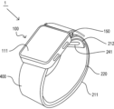
- FIG. 1 is a diagram showing the appearance of a biological information measuring device according to a first embodiment.
- FIG. 2 is a diagram showing the appearance of the biological information measuring device according to the first embodiment when it is worn.
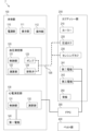
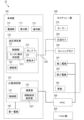
- FIG. 3 is a functional block diagram of the biological information measuring device according to the first embodiment.
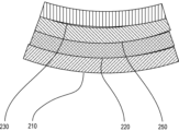
- FIG. 4 is a cross-sectional view of the cuff assembly portion of the biological information measuring device according to the first embodiment.
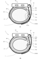
- FIGS. 5A and 5B are diagrams showing how the biological information measuring device according to the first embodiment is used.
- FIGS. 6A and 6B are diagrams showing an electrode connection structure according to Example 1.
- FIGS. 7A and 7B are diagrams showing an electrode connection structure according to Example 1.
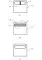
- FIGS. 8A to 8C are diagrams showing the structure of an electrode according to Modification 1 of Example 1.
- FIG. 9 is a diagram showing how the biological information measuring device according to the second modification of the first embodiment is used.
- FIG. 10 is a diagram showing how the biological information measuring device according to the second embodiment is used.
- FIG. 11(A) is a diagram showing the configuration of the electrodes of the biological information measuring device according to Example 3, and FIGS. 11(B) and (C) are diagrams showing the usage state of the biological information measuring device according to Example 3. It is a diagram.
- FIG. 12 is a diagram showing the configuration of a biological information measuring device according to the fourth embodiment.
- FIG. 13 is a functional block diagram of the biological information measuring device according to the fifth embodiment.
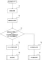
- FIG. 14 is a flowchart of the wrapping method determination process of the biological information measuring device according to the fifth embodiment.
- Example 1 An example of an embodiment of the present invention will be described below. However, unless otherwise specified, the dimensions, materials, shapes, relative positions, etc. of the components described in this embodiment are not intended to limit the scope of the present invention.
- FIG. 1 and 2 are schematic diagrams showing the external configuration of a biological information measuring device 1 according to this embodiment.
- FIG. 3 is a functional block diagram showing the functional configuration of the biological information measuring device 1 according to this embodiment.
- the biological information measuring device 1 generally has a main body portion 100, a cuff assembly portion 200, and a belt portion 400. Electrocardiographic waveforms can be measured.
- the belt portion 400 includes a hook-and-loop fastener 411 having a hook.
- the main body portion 100 is provided with a belt loop portion 150 having an annular belt loop for inserting the belt portion 400 therethrough.
- the belt portion 400 is wrapped around the wrist T and inserted through the belt loop portion 150, and the hook-and-loop fastener 411 is attached to the belt portion 400 (a loop is formed in which the hook engages). ) to fix it at any position.
- the biological information measuring device 1 also uses an FPC (Flexible 300 (not shown in FIGS. 1 and 2).
- the wrist corresponds to the part to be measured according to the present invention.
- the main body section 100 includes a housing 101, a power supply section 110, a display section 111, an operation section 112, a blood pressure measurement section 120, an electrocardiogram measurement section 130, and a first electrode 140.
- the first electrode 140 includes the entire housing 101 of the main body 100 and the operation buttons 1121 and 1122.
- the configuration of the first electrode 140 is not limited to this, and may be a part of the housing 101 or a structure independent from the housing 101.
- the power supply unit 110 is configured to include a battery that supplies power necessary for operating the device.
- the battery may be a secondary battery such as a lithium ion battery, or a primary battery.
- the display unit 111 is configured to include a display device such as a liquid crystal display, and may include an LED indicator or the like.
- the operation section 112 specifically includes operation buttons 1121 and 1122 arranged on the side surface of the housing 101 of the main body section 100. A configuration in which the display unit 111 such as a touch panel display and the operation unit 112 are integrated may be used.
- the blood pressure measurement unit 120 is a functional unit that controls a cuff assembly unit 200 (described later) and measures the user's blood pressure based on information obtained thereby, and controls a control unit 121, a calculation unit 122, a pump 123, and an exhaust valve 124.
- the control unit 121 and the calculation unit 122 are configured by, for example, a CPU (Central Processing Unit), and may have a storage unit configured by a RAM (Random Access Memory) or the like, although not shown.
- the pump 123 and the exhaust valve 124 correspond to the pump and valve of the present invention, respectively.
- the control unit 121 is a functional unit that controls the blood pressure measurement unit 120, and controls the cuff pressure of the cuff assembly unit 200 via the calculation unit 122, the pump 123, etc., and controls the wrist T on which the biological information measurement device 1 is attached. Obtain information to measure the user's blood pressure from the arteries located in the. The calculation unit 122 measures the blood pressure value based on the information acquired in this way.
- the pump 123 and the exhaust valve 124 are mechanisms that communicate with a compression cuff 220 and a sensing cuff 230 (described later) via a flow path 125 through which air flows, and are responsible for supplying and discharging air to the compression cuff 220 and sensing cuff 230. .
- the electrocardiogram measurement unit 130 is a functional unit that measures the electrocardiogram waveform of the user based on the potential difference between the first electrode 140 and the second electrode 241 that are in contact with the human body surface, and includes a control unit 131 and a calculation unit 132. There is.
- the control unit 131 and the calculation unit 132 are configured by the above-mentioned CPU and the like. From the viewpoint of hardware, the control section 131 and the calculation section 132 may have a common configuration with the control section 121 and the calculation section 122 of the blood pressure measurement section 120.
- both the blood pressure measurement section 120 and the electrocardiogram measurement section 130 include an AD conversion circuit, an amplifier, a filter, etc. (not shown) in addition to the above-mentioned CPU and RAM, but these are constructed using known techniques. Therefore, the explanation will be omitted.
- the cuff assembly section 200 includes a curler 210, a compression cuff 220, a sensing cuff 230, a second electrode 241, a third electrode 242, and a back plate 250.
- the curler 210 is a base member for holding the compression cuff 220.
- FIG. 4 is a cross-sectional view schematically showing the internal structure of the area surrounded by the dotted line in FIG. 1 in the cuff assembly section 200.
- the cuff assembly part 200 has a structure in which a compression cuff 220, a back plate 250, and a sensing cuff 230 are stacked in this order, with the curler 210 being the outermost part.
- compression cuff 220 (and sensing cuff 230) corresponds to the fluid bag of the present invention.
- the compression cuff 220 has the role of tightening the wrist T on which it is attached by being inflated by air sent from the pump 123 and applying external pressure to an artery (not shown) existing in the wrist T.
- the sensing cuff 230 (not shown) is a fluid bag for detecting the pressure applied to the area compressed by the compression cuff 220, and when a small amount of air is contained inside the sensing cuff 230, the internal pressure is The pressure applied to the compression site is measured by detection by a meter (not shown).
- the back plate 250 (not shown) is a flexible flat member disposed between the compression cuff 220 and the sensing cuff 230, and prevents excessive bending of the sensing cuff 230 during compression by the compression cuff 220. This suppresses the pressure distribution within the sensing cuff 230.
- air corresponds to the fluid of the present invention.
- the second electrode 241 and the third electrode 242 are both electrodes placed at a position where they can come into contact with the surface of the human body, the second electrode 241 is an electrode for measuring an electrocardiogram waveform, and the third electrode 242 is used to set a reference potential. Functions as a GND (ground) electrode.
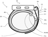
- FIG. 5 shows a state in which the biological information measuring device 1 is attached to the user's wrist T.
- a compression cuff 220 is provided along the extension direction (direction around the wrist T) of a curler 210 formed in a C-shape that curves along the circumferential direction of the wrist T.
- the curler 210 has a first curler part 211 that is longer in the extension direction and a second curler part 212 that is shorter in the extension direction with respect to the position where the main body part 100 is provided.
- the first curler portion 211 extends from the main body portion 100 located on the back side of the wrist T so as to cover the artery side of the wrist T.
- the second curler part 212 extends in the circumferential direction of the wrist T on the opposite side to the first curler part 211.
- the compression cuff 220 is provided along the first curler section 211 of the curler 210, and the distal end 220a of the compression cuff 220 in the circumferential direction (the direction of extension of the first curler section 211) is located along the direction of extension of the first curler section 211. It is located near the tip 211a.
- the compression cuff 220 is provided continuously from the first curler part 211 side and also along the second curler part 212, but the tip of the compression cuff 220 in the circumferential direction (extension direction of the second curler part 212)
- the portion 220b is located apart from the distal end portion 212a of the second curler portion 212 of the curler 210 in the extending direction.
- Curler 210 corresponds to the curler of the present invention.
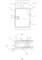
- FIG. 6(A) is a perspective view of the biological information measuring device 1 seen from the outside of the electrode support part 2121
- FIG. 6(B) is a perspective view of the part surrounded by the broken line in FIG. 6(A) perpendicular to the circumferential direction. It is a sectional view seen from the direction.
- a second electrode 241 and a third electrode 242 are arranged inside this electrode support portion 2121.
- the second electrode 241 and the third electrode 242 are made of a conductive member such as stainless steel, and each has a substantially semicircular cross section perpendicular to the circumferential direction and an oval shape divided into two in the circumferential direction. They are arranged at predetermined intervals in orthogonal directions.
- the FPC 300 is arranged along the second curler part 212 of the curler 210 from the main body part 100 toward the second electrode 241 and the third electrode 242.
- the ends of the FPC 300 in the circumferential direction (extending direction of the second curler section 212) and the second electrode 241 and the third electrode 242 are connected by contact pins 310 and 320 on leaf springs, respectively.
- FIG. 7(A) is a diagram showing a part of the internal structure of the main body section 100 when viewed from the front of the display section 111 of the biological information measuring device 1
- FIG. 7(B) is a diagram showing the center of the pogo pins 161 and 162.
- FIG. 3 is a diagram showing a connection structure between a substrate 160 and an FPC 300 in a cross section taken through the FIG. As shown in FIGS. 7A and 7B, the substrate 160 housed inside the main body 100 and the FPC 300 are electrically connected by pogo pins 161 and 162.
- 6(A), FIG. 6(B), FIG. 7(A), and FIG. 7(B) structures unnecessary for explanation are omitted as appropriate.
- the second electrode 241 and the third electrode 242 are connected to the distal end portion 220b of the compression cuff 220 in the circumferential direction (extending direction of the second curler portion 212).
- the distal end portion 220b is located at a predetermined distance apart from the distal end portion 220b.
- the belt portion 400 is wrapped around the wrist T on the outer peripheral side of the curler 210, the belt loop portion 150 is inserted through the belt portion 400, and the belt portion 400 is fixed with the hook-and-loop fastener 411, and the state before the compression cuff 220 is inflated is shown in FIG. 5A.
- the state after being expanded is shown in FIG. 5(B).
- the second electrode 241 and the third electrode 242 extend beyond the distal end portion 220b in the circumferential direction (extending direction of the second curler portion 212) of the inflating compression cuff 220. It is provided on the extending electrode support section 2121.
- the change in the contact state is a change in the contact state, such as the contact position, contact angle, and contact area between the second electrode 241 and the third electrode 242 and the wrist T.
- the compression cuff 220 which is disposed inside the tip 211a of the first curler part 211 of the curler 210, is located outside the electrode support part 2121 of the curler 210.
- the expansion of the cuff 220 presses the electrode support portion 2121 inward. This pressing of the compression cuff 220 toward the inner diameter side also increases the contact pressure between the second electrode 241 and the third electrode 242 and the wrist T, so the state of contact between the second electrode 241 and the third electrode 242 and the wrist T changes. is more suppressed.
- the tip 220a of the compression cuff 220 in the circumferential direction may not reach the outer diameter side of the electrode support part 2121. Even in cases where the belt portion 400 is wrapped around the wrist T, the movement of the electrode support portion 2121 toward the outer diameter side is suppressed, so that the movement and posture of the second electrode 241 and the third electrode 242 due to the expansion of the compression cuff 220 is prevented. Changes in the contact state between the second electrode 241 and the third electrode 242 and the wrist T are suppressed.
- the electrode support portion 2121 corresponds to the support member and contact state stabilizing means of the present invention. Inflation of the compression cuff 220 corresponds to a change in volume of the fluid bladder of the present invention.
- the shape of the second electrode 241 and the third electrode 242 is not limited to a semicircular shape in the direction orthogonal to the circumferential direction as shown in FIG.
- Other curved shapes such as a curved line that is convex toward the surface, may also be used.
- the cuff assembly portion 200 and the belt portion 400 are wrapped around the wrist T with the main body portion 100 facing toward the back of the hand. Then, the belt section 400 is passed through the belt loop section 150 and then folded back, the hook-and-loop fastener 411 of the belt section 400 is attached to an arbitrary position on the belt section 400, and the biological information measuring device 1 is attached to the wrist T. At this time, the sensor is worn so that the sensing cuff 230 is positioned on the palm side of the wrist T.
- measurement is started by operating the operation button 1121 (or 1122). Specifically, by injecting air into the compression cuff 220 and inflating it, the wrist T (artery) is compressed, the artery is occluded and blood flow is temporarily stopped, and then the air is gradually expelled from the compression cuff 220.
- the cuff 230 contracts to release the pressure and return blood flow to the artery, and the sensing cuff 230 measures the pressure at this time. That is, blood pressure measurement is performed using a so-called oscillometric method.
- the second electrode 241 and the third electrode 242 are in contact with the surfaces T1 and T2 of the wrist T (see FIG. 5(A)). It is in a state of being forced (pressed). Therefore, by touching the first electrode 140 provided in the housing 101 of the main body 100 with the finger that is not wearing the biological information measuring device 1, the potential difference between the first electrode 140 and the second electrode 241 can be increased. Based on this, electrocardiographic waveforms can be measured using the so-called I-lead method.
- the finger on which the biological information measuring device 1 is not attached corresponds to the first part of the present invention
- the surfaces T1 and T2 of the wrist T correspond to the second and third parts of the present invention, respectively.
- the biological information measuring device 1 it is possible to measure blood pressure values and electrocardiographic waveforms simultaneously and accurately with a portable device that is worn on the wrist T.
- FIGS. 8(A) and 8(B) are views of the electrode support portion 2121 of the curler 210 provided with the second electrode 241 and the third electrode 242, viewed from inside.
- the second electrode 241 and the third electrode 242 are arranged apart from each other, but as shown in FIG. A separator 260 made of the following members may be arranged. In this way, by arranging the second electrode 241 and the third electrode 242 with the separator 260 in between, the second electrode 241 and the third electrode 242 are insulated, and the second electrode 241 and the third electrode 242 are separated. The interval can be made smaller. At this time, in FIG.
- the second electrode 241 is placed on the left side and the third electrode 242 is placed on the right side, but the positions of the second electrode 241 and third electrode 242 are swapped.
- the second electrode 241 may be placed on the right side, and the third electrode 242 may be placed on the left side.
- the separator 260 corresponds to the insulating member of the present invention.
- the arrangement direction of the second electrode 241 and the third electrode 242 is not limited to the direction perpendicular to the circumferential direction. As shown in FIG. 8(B), the second electrode 241 may be arranged along the circumferential direction on the proximal end side (lower side in FIG. 8(B)) and the third electrode 242 may be arranged on the distal end side. Often, a separator made of an insulating material may be placed between the second electrode 241 and the third electrode 242.
- FIG. 8C shows a modification in which the third electrode 242 is omitted and only the second electrode 241 is provided on the electrode support portion 2121. In this way, by omitting the third electrode 242 that functions as a GND electrode, the number of members can be reduced and the structure can be simplified.
- FIG. 9 is a side view showing the configuration of a biological information measuring device 11 according to a second modification of the first embodiment.
- the same components as the biological information measuring device 1 according to the first embodiment are designated by the same reference numerals, and detailed description thereof will be omitted.
- the biological information measuring device 11 has the same configuration as the biological information measuring device 1 except for the arrangement of the second electrode 241 and the third electrode 242.
- the second electrode 241 and the third electrode 242 are arranged on the electrode support part 2121 provided on the tip side of the second curler part 212 of the curler 210, but the biological information measuring device according to the second modification example In the device 11, the second electrode 241 and the third electrode 242 are arranged on an electrode support part 2111 provided on the tip side of the first curler part 211 of the curler 210.
- the distal end 220a of the compression cuff 220 in the circumferential direction (the extending direction of the first curler section 211) is located at a predetermined distance from the distal end 211a of the curler 210 in the extending direction.
- the first curler part 211 of the curler 210 extends beyond the tip part 220a in the circumferential direction (extension direction of the first curler part 211) of the compression cuff 220 arranged inside the curler 210 along the first curler part 211.
- An electrode support portion 2111 is provided at a position of the curler 210 beyond the tip 220a of the compression cuff 220.
- a second electrode 241 and a third electrode 242 are arranged inside this electrode support portion 2111.
- the second electrode 241 and the third electrode 242 are made of a conductive member such as stainless steel, which has a substantially semicircular cross section in the circumferential direction and an oval shape in a direction perpendicular to the circumferential direction. They are arranged in a line in a direction perpendicular to the circumferential direction.
- the second electrode 241 and the third electrode 242 and the substrate 160 housed inside the main body 100 are electrically connected via the FPC 300.
- the second electrode 241 and the third electrode 242 are placed beyond the tip 220a of the compression cuff 220 in the circumferential direction (extending direction of the first curler part 211) and spaced apart from the tip 220a by a predetermined distance. It is placed in the correct position.
- FIG. 9 shows a state in which the belt part 400 is wrapped around the wrist T on the outer circumferential side of the curler 210, the belt loop part 150 is inserted, and the belt part 400 is fixed with a hook and loop fastener 411, and the compression cuff 220 is not inflated.
- the compression cuff 220 disposed on the inside When the compression cuff 220 disposed on the inside is inflated, the C-shaped curler 210 is pushed out and moved toward the outer diameter side, as described with reference to FIGS. 5(A) and 5(B). .
- the second electrode 241 and the third electrode 242 extend beyond the distal end portion 220a in the circumferential direction (extending direction of the first curler portion 211) of the inflating compression cuff 220.
- the electrode support portion 2111 extends from the electrode support portion 2111 to the electrode support portion 2111.
- the compression cuff 220 disposed at the tip 212a of the second curler part 212 of the curler 210 is located on the outer diameter side of the electrode support part 2111 of the curler 210, so that the electrode is supported by the expansion of the compression cuff 220.
- the portion 2111 is pressed inward.
- This pressing of the compression cuff 220 toward the inner diameter side also increases the contact pressure between the second electrode 241 and the third electrode 242 and the wrist T, so that the state of contact between the second electrode 241 and the third electrode 242 and the wrist T is further improved. suppressed.
- the tip portion 220b of the compression cuff 220 in the circumferential direction may not reach the outer diameter side of the electrode support portion 2111; Even in this case, the movement of the electrode support part 2111 toward the outer diameter side is suppressed by the belt part 400 wrapped around the wrist T, so that the movement of the second electrode 241 and the third electrode 242 due to the expansion of the compression cuff 220 and Posture changes are limited to a predetermined range, and changes in the state of contact between the second electrode 241 and the third electrode 242 and the wrist T are suppressed.
- the electrode support portion 2111 corresponds to the support member and contact state stabilizing means of the present invention.
- Modification 2 as well, the configuration of Modification 1 shown in FIGS. 5(A) to 5(C) may be applied to the configurations of the second electrode 241 and third electrode 242.
- Example 2 A biological information measuring device 12 according to a second embodiment of the present invention will be described below with reference to the drawings.
- the same components as the biological information measuring device 1 according to the first embodiment are designated by the same reference numerals, and detailed description thereof will be omitted.
- FIG. 10 is a side view showing the configuration of the biological information measuring device 12 according to the second embodiment.
- the biological information measuring device 12 in the biological information measuring device 12, only the first curler part 211 of the curler 210 that extends from the main body part 100 to cover the artery side of the wrist T is shown, but with respect to the circumferential direction of the wrist T.
- a second curler section 212 may be provided that extends on the opposite side of the first curler section 211 and has an appropriate extension.
- the compression cuff 220 is provided only on the inner peripheral side of the first curler part 211 with respect to the main body part 100, but depending on the configuration of the curler 210, the compression cuff 220 is provided in the circumferential direction of the wrist T as appropriate. It may be provided up to the position.
- the second electrode 241 and the third electrode 242 are arranged on the inner circumferential surface 412 of the electrode support section 410 on the opposite side from the end section 401 of the belt section 400 on the main body section 100 side.
- the electrode support portion 410 of the belt portion 400 is provided at a position separated from the distal end portion 220a of the compression cuff 220 in the circumferential direction (extending direction of the first curler portion 211) by a predetermined distance.
- the second electrode 241 and the third electrode 242 are electrically connected to the substrate 160 housed inside the main body section 100 by an FPC provided on the belt section 400.
- FIG. 10 shows the state before the compression cuff 220 is inflated.
- the compression cuff 220 is inflated, the C-shaped curler 210 is pushed out and moved toward the outer periphery of the curler 210, as described with reference to FIGS. 5(A) and 5(B).
- the belt portion 400 and the electrode support portion 410 that are wrapped around each other also move toward the outer diameter side.
- the second electrode 241 and the third electrode 242 are connected to the electrode support portion 410 that extends beyond the distal end portion 220a in the circumferential direction (extending direction of the first curler portion 211) of the inflating compression cuff 220. It is set in.
- the electrode support section 410 that constitutes a part of the belt section 400 corresponds to the support member and contact state stabilizing means of the present invention. This embodiment can also be combined with each embodiment described later. Further, although the biological information measuring device 12 shown in FIG. 10 is provided with a curler 210, the structure may be such that the curler 210 is omitted.
- a biological information measuring device 13 according to a third embodiment of the present invention will be described below with reference to the drawings.
- the same components as the biological information measuring device 1 according to the first embodiment are designated by the same reference numerals, and detailed description thereof will be omitted.
- the biological information measuring device 13 differs from the biological information measuring device 1 in the structure of the electrode support portion 2112 provided on the circumferential tip side of the second curler portion 212 of the curler 210, the second electrode 241, and the third electrode 242.
- the configuration of is common.
- the electrode support section 2122 is provided on the distal end side of the second curler section 212 of the curler 210 in the extending direction. Further, the electrode support portion 2122 extends beyond the circumferential tip portion 220b of the compression cuff 220 provided inside the curler 210.
- the second electrode 241 and the third electrode 242 are arranged inside the distal end 2122a of the electrode support section 2122, but can be arranged at appropriate positions from the distal end 220a of the compression cuff 220 in the circumferential direction.
- FIG. 11(A) is a diagram schematically showing the relationship between the second electrode 241 and the third electrode 242 and the insulating coating 270 according to Example 3 in a cross section in a direction perpendicular to the circumferential direction.
- the second electrode 241 and the third electrode 242 have their proximal ends (electrode support 2112 side or outside) covered with an insulating coating 270. Therefore, of the second electrode 241 and the third electrode 242, only the portion exposed through the opening 271 (indicated by a dotted line in FIG. 11(A)) formed by the insulating coating 270 is electrically connected to the wrist T. will come into contact with.
- the insulating coating 270 has a function of limiting the contact portions of the second electrode 241 and the third electrode 242 with the wrist T.
- the area covered by the insulating coating 270 and the range of the opening 271 depend on the shapes of the second electrode 241 and the third electrode 242, the circumferential length of the electrode support 2122, the thickness of the compression cuff 220 before and after inflation, etc. Although it may vary depending on the situation, when the biological information measuring device 13 is attached to the wrist T, the portions of the second electrode 241 and the third electrode 242 exposed from the opening 271 are common before and after the compression cuff 220 is inflated. Set it so that it touches the wrist T.
- the height from the base end side of the insulating coating 270 is defined as The height may be different between the distal end side in the circumferential direction and the proximal end side in the circumferential direction (main body part 100 side), for example, the height may be lower at the distal end side in the circumferential direction and higher at the proximal end side in the circumferential direction. Can be set to .
- FIG. 11(B) shows a state in which the compression cuff 220 is inflated from the state in FIG. 11(B). Compared to the state shown in FIG. 7B before the compression cuff 220 is inflated, in the state shown in FIG. This causes the second electrode 241 and the third electrode 242 to rotate clockwise in the figure.
- the contact range between the second electrode 241 and the third electrode 242 and the wrist T may change.
- the portions of the second electrode 241 and the third electrode 242 exposed from the opening 271 are in electrical contact with the wrist T both before and after the compression cuff 220 is inflated.
- the contact portion between the second electrode 241 and the third electrode 242 and the wrist T does not change due to the expansion of the compression cuff 220.
- the parts of the second electrode 241 and the third electrode 242 that come into contact with the wrist T only at any stage of inflation of the compression cuff 220 are covered with the insulating coating 270, so that the parts of the second electrode 241 and the third electrode 242 are electrically isolated from the wrist T. It can be kept in an insulated state so that it does not come into contact with the
- the insulating coating 270 and the opening 271 correspond to the covering portion and the opening of the present invention, respectively. Further, the insulating coating 270 and the opening 271 correspond to the contact state stabilizing means of the present invention.
- the state of contact between the second electrode 241 and the third electrode 242 and the wrist T can be stabilized regardless of the expansion of the compression cuff 220. Further, by providing such an insulating coating 270, the second electrode 241 and the third electrode 242 can be extended beyond the tip 220a of the compression cuff 220 in the circumferential direction (extending direction of the second curler part 212), and 220a, the contact state between the second electrode 241 and the third electrode 242 and the wrist T can be stabilized.
- the insulating coating 270 in the third embodiment can also be applied to the second electrode 241 and the third electrode 242 in the biological information measuring device 1 according to the first modification of the first embodiment.
- the insulating coating 270 in the third embodiment is arranged such that the second electrode 241 is attached to the electrode support portion 2112 extending to the tip of the first curler portion 211 of the curler 210, as in the biological information measuring device 13 according to the second modification of the first embodiment.
- the present invention can also be applied when the third electrode 242 is provided.
- a biological information measuring device 14 according to a fourth embodiment of the present invention will be described below with reference to the drawings.
- the same components as the biological information measuring device 1 according to the first embodiment are designated by the same reference numerals, and detailed description thereof will be omitted.
- the structure of the electrode support part 2123 of the curler 210 on which the second electrode 241 and the third electrode 242 are arranged is different from that in the biological information measuring device 1 according to the first example.
- the configuration of is common.
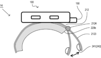
- an electrode support section 2123 is connected to the tip of the second curler section 212 of the curler 210 by a hinge section 2124 that is rotatable about an axis perpendicular to the circumferential direction.
- the electrode support portion 2121 of the curler 210 may be deformed by the expansion of the compression cuff 220.
- the electrode support part 2123 corresponds to the support member and the second electrode support part of the present invention
- the electrode support part 2123 and the hinge part 2124 correspond to the contact state detection means of the present invention.
- the hinge portion 2324 is provided only at one location between the tip of the second curler portion 212 of the curler 210 and the electrode support portion 2123, Similarly, hinge parts that can rotate in a direction perpendicular to the circumferential direction may be provided at a plurality of locations, or the hinge parts may be arranged over the entire circumferential direction of the curler 210 like a wrist watch band.
- a biological information measuring device 15 according to a fifth embodiment of the present invention will be described below with reference to the drawings.
- the same components as the biological information measuring device 1 according to the first embodiment are designated by the same reference numerals, and detailed description thereof will be omitted.
- the biological information measuring device 15 according to the fifth embodiment has the same hardware configuration as the first to fourth embodiments.
- FIG. 13 shows a functional block diagram of the biological information measuring device 15 according to this embodiment.
- the biological information measuring device 15 differs from the biological information measuring device 1 according to the first embodiment shown in FIG. 3 in the block configuration of the calculation section 132 of the electrocardiogram measuring section 130 and the control section 121 of the blood pressure measuring section 120.
- the calculation section 132 includes a contact resistance measurement section 1321
- the control section 121 includes a belt snugness determination section 1221.
- the functions of the contact resistance measuring section 1321 and the belt snugness determining section 1221 will be described later.
- the contact resistance measuring section 1321 and the belt snug winding determining section 1221 correspond to the contact resistance measuring and winding method determining section of the present invention, respectively.
- FIG. 14 shows a flowchart illustrating the procedure of belt tightness determination processing in the biological information measuring device 15.
- a user wears the biological information measuring device 15 and starts blood pressure measurement (step S1). Specifically, the compression cuff 220, the curler 210, and the belt part 400 are wrapped around the wrist T, the belt part 400 is inserted into the belt loop part 150, the belt part 400 is fixed with a hook-and-loop fastener 411, and a predetermined measurement posture is taken. , while pressing down the measurement switch, touch the first electrode 140 with the finger of the hand on the opposite side to the hand on which the biological information measuring device 15 is attached.
- the contact resistance measuring unit 1321 measures the contact resistance between the second electrode 241 and the third electrode 242 and the wrist T by conducting the second electrode 241 and the third electrode 242 (step S2). At this time, the contact resistance may be measured by electrical continuity between the first electrode 140 and the second electrode 141. Furthermore, the body part of the person whose contact resistance is measured is not limited to the wrist T.
- the belt snugness determining unit 1221 determines whether the contact resistance is less than or equal to a threshold value and the variation in contact resistance over a predetermined time is less than or equal to a threshold value (step S3). At this time, if the contact resistance is less than the threshold value and the variation in contact resistance for a predetermined time is less than the threshold value, the belt snugness determination unit 1221 determines that the belt portion 400 is snugly wrapped around the wrist T. , it is determined that the biological information measuring device 15 is properly attached (step S4), and the control unit 121 closes the exhaust valve 124, drives the pump 123, and pressurizes the compression cuff 220 and the sensing cuff 230. Start (step S5).
- the belt snug winding determination unit 1221 determines that the belt portion 400 is loosely wound around the wrist T. It is determined that the biological information measuring device 14 is not properly attached (step S6), and the control unit 121 performs a loose winding process (step S7).
- the display unit 111 may display that the belt part 400 is not wrapped tightly around the wrist T and the contact state of the electrodes is not appropriate. After performing such a display, pressurization by the compression cuff 220 or the like may be started, or the user may be prompted to rewind the belt portion 400 without starting pressurization.
- the display on the display unit 111 may be a message or mark to that effect, a blinking lamp or the like, lighting in a predetermined color, or an audio output.
- a section may be provided to output a voice message to that effect.
- the configuration of the second electrode 241, third electrode 242, etc. for electrocardiographic waveform measurement can be used to determine whether or not the winding of the belt portion 400 is appropriate when measuring blood pressure. This is highly convenient because it is possible to determine whether or not the way the belt portion 400 is wound is appropriate even before the blood pressure measurement starts.
- the belt part 400, the compression cuff 220, and the curler 210 are configured separately, but the belt part 400 and the compression cuff 220 are integrated.
- the belt portion 400 and the curler 210 may be integrated. In this way, the device configuration is simplified and handling becomes easier.
Landscapes
- Health & Medical Sciences (AREA)
- Life Sciences & Earth Sciences (AREA)
- Molecular Biology (AREA)
- Surgery (AREA)
- Biophysics (AREA)
- Pathology (AREA)
- Engineering & Computer Science (AREA)
- Biomedical Technology (AREA)
- Heart & Thoracic Surgery (AREA)
- Medical Informatics (AREA)
- Veterinary Medicine (AREA)
- Physics & Mathematics (AREA)
- Animal Behavior & Ethology (AREA)
- General Health & Medical Sciences (AREA)
- Public Health (AREA)
- Cardiology (AREA)
- Vascular Medicine (AREA)
- Physiology (AREA)
- Ophthalmology & Optometry (AREA)
- Measuring Pulse, Heart Rate, Blood Pressure Or Blood Flow (AREA)
- Measurement And Recording Of Electrical Phenomena And Electrical Characteristics Of The Living Body (AREA)
Abstract
Description
前記被測定者の被測定部位の周方向に巻き付けられる流体袋と、
前記流体袋内に流体を供給するポンプと、
前記流体袋に連通する前記流体の流路に設けられた弁と、
前記ポンプから前記流体を供給して前記流体袋を膨張させることにより前記被測定部位を圧迫し、又は、前記弁を制御して前記流体袋内の前記流体を排出して前記流体袋を収縮させることにより前記被測定部位に対する圧迫を解除し、前記被測定部位の血圧を測定する血圧測定部と、
前記被測定者の第一部位に接触する第一電極と、
前記第一部位とは異なる前記被測定者の第二部位に接触する第二電極であって、前記周方向に延びる前記流体袋に接続され、該流体袋の該周方向の端部からさらに該周方向に延びる支持部材に支持され、該端部から該周方向に所定距離を隔てた位置に配置された第二電極と、
前記第一電極及び前記第二電極を通じて前記被測定者の心電波形を測定する心電測定部と、
前記流体袋の外周側に巻かれて、前記生体情報測定装置を前記被測定部位に固定するベルト部と、
前記流体袋の体積変化に伴う、前記第二電極の前記第二部位との接触状態の変化を抑制する接触状態安定化手段と、
を備えたことを特徴とする。
前記開口部から露出する前記第二電極の一部は、前記流体袋の前記体積変化の前後を通じて前記第二部位に接触するようにしてもよい。
該カーラーと前記ベルト部とを一体に設けてもよい。
前記第三電極は、絶縁性部材を介して前記第二電極とともに、前記支持部材に支持され、
前記接触状態安定化手段は、前記第三電極と前記第三部位との前記接触状態の変化を抑制するようにしてもよい。
前記接触抵抗に基づいて、前記被測定者による前記ベルト部の巻き方の適否を判定する巻き方判定部と、
を備えるようにしてもよい。
以下に、本発明の実施形態の一例について説明する。但し、この実施例に記載されている構成部品の寸法、材質、形状、その相対配置などは、特に記載がない限りは、この発明の範囲をそれらのみに限定する趣旨のものではない。
図1及び図2は、本実施例に係る生体情報測定装置1の外観構成を示す概略図である。図3は、本実施例に係る生体情報測定装置1の機能構成を示す機能ブロック図である。
生体情報測定装置1をユーザーの手首Tに装着した状態を示す図5に基づいてカフアッシー部200の構造について説明する。本実施例では、手首Tの周方向に倣って湾曲するC字状に形成されたカーラー210の延長方向(手首Tの周囲を回る方向)に沿って圧迫カフ220が設けられている。カーラー210は、本体部100が設けられた位置を基準として、延長方向により長い第一カーラー部211と、延長方向により短い第二カーラー部212を有する。第一カーラー部211は、手首Tの甲側に位置する本体部100から手首Tの動脈側を覆うように延びている。一方、第二カーラー部212は、手首Tの周方向に対して第一カーラー部211とは反対側に延びている。圧迫カフ220はカーラー210の第一カーラー部211に沿って設けられ、圧迫カフ220の、周方向(第一カーラー部211の延長方向)の先端部220aは、第一カーラー部211の延長方向の先端部211a近傍に位置する。また、圧迫カフ220は、第一カーラー部211側から連続して、第二カーラー部212に沿っても設けられるが、圧迫カフ220の、周方向(第二カーラー部212の延長方向)の先端部220bは、カーラー210の第二カーラー部212の延長方向の先端部212aとは離間して位置する。カーラー210は本発明のカーラーに相当する。
以上のような構成を有する生体情報測定装置1により生体情報の測定を行うには、まず、本体部100が手の甲側を向くようにして、カフアッシー部200とベルト部400を手首Tに巻き付ける。そして、ベルト部400をベルト通し部150に通したうえで折り返し、ベルト部400の面ファスナー411をベルト部400の任意の位置に貼り付けて、手首Tに生体情報測定装置1を装着する。この際、センシングカフ230が手首Tの手の平側に位置するように装着を行う。
図8(A)及び図8(B)は、第二電極241及び第三電極242が設けられたカーラー210の電極支持部2121を内側から見た図である。
実施例1では、第二電極241と第三電極242とを離間させて配置しているが、図8(A)に示すように、第二電極241と第三電極242との間に絶縁性の部材からなるセパレータ260を配置してもよい。このように、セパレータ260を隔てて第二電極241と第三電極242を配置することにより、第二電極241と第三電極242の間を絶縁するとともに、第二電極241及び第三電極242の間隔を小さくすることができる。このとき、図5(A)では、第二電極241が向かって左側に配置され、第三電極242が向かって右側に配置されているが、第二電極241及び第三電極242の位置を入れ替え、第二電極241を向かって右側、第三電極242を向かって左側に配置してもよい。ここでは、セパレータ260が本発明の絶縁性部材に相当する。
図9は、実施例1の変形例2に係る生体情報測定装置11の構成を示す側面図である。実施例1に係る生体情報測定装置1と同様の構成については同様の符号を用いて詳細な説明を省略する。
生体情報測定装置11は、第二電極241及び第三電極242の配置を除いて、生体情報測定装置1と同様の構成を有する。
以下に、図面を参照して本発明の実施例2に係る生体情報測定装置12について説明する。実施例1に係る生体情報測定装置1と同様の構成については同様の符号を用いて詳細な説明は省略する。
図10では、生体情報測定装置12では、カーラー210のうち、本体部100から手首Tの動脈側を覆うように延びる第一カーラー部211のみを示しているが、手首Tの周方向に対して第一カーラー部211とは反対側に延び、適宜の延長を有する第二カーラー部212を設けてもよい。また、図10では、圧迫カフ220は、本体部100に対して第一カーラー部211の内周側にのみ設けられているが、カーラー210の構成に応じて、手首Tの周方向に適宜の位置まで設けてもよい。
本実施例は、後述する各実施例と組み合わせることも可能である。また、図10に示す生体情報測定装置12では、カーラー210を設けているが、カーラー210を省略した構成としてもよい。
以下に、図面を参照して本発明の実施例3に係る生体情報測定装置13について説明する。実施例1に係る生体情報測定装置1と同様の構成については同様の符号を用いて詳細な説明は省略する。
以下に、図面を参照して本発明の実施例4に係る生体情報測定装置14について説明する。実施例1に係る生体情報測定装置1と同様の構成については同様の符号を用いて詳細な説明は省略する。
以下に、図面を参照して本発明の実施例5に係る生体情報測定装置15について説明する。実施例1に係る生体情報測定装置1と同様の構成については同様の符号を用いて詳細な説明は省略する。
まず、ユーザーが、生体情報測定装置15を装着して血圧測定を開始する(ステップS1)。具体的には、手首Tに圧迫カフ220、カーラー210及びベルト部400を巻き付け、ベルト部400をベルト通し部150に挿通し、面ファスナー411によってベルト部400を固定し、所定の測定姿勢をとり、測定スイッチを押下するとともに、生体情報測定装置15が装着された手と反対側の手の指で第一電極140に触れる。
このとき、接触抵抗が閾値以下であり、かつ、所定時間の接触抵抗のばらつきが閾値以下であれば、ベルトぴったり巻き判定部1221は、ぴったり巻き、すなわち、ベルト部400が手首Tにぴったり巻き付けられ、生体情報測定装置15が適切に装着されていると判定され(ステップS4)、制御部121は、排気弁124を閉じ、ポンプ123を駆動して、圧迫カフ220及びセンシングカフ230による加圧を開始する(ステップS5)。
一方、接触抵抗が閾値を超え、又は、所定時間の接触抵抗のばらつきが閾値を超える場合には、ベルトぴったり巻き判定部1221は、ゆる巻き、すなわち、ベルト部400が手首Tにゆるく巻き付けられ、生体情報測定装置14が適切に装着されていないと判定し(ステップS6)、制御部121はゆる巻き処理を行う(ステップS7)。ゆる巻き処理としては、ベルト部400が手首Tにぴったり巻かれておらず、電極の接触状態が適切でない旨を表示部111に表示するようにしてもよい。このような表示を行った上で、圧迫カフ220等による加圧を開始してもよいし、加圧を開始せずにユーザーにベルト部400の巻き直しを促してもよい。ゆる巻き処理としては、ベルト部400がぴったり巻かれていない旨の表示は行わず、圧迫カフ220等の加圧を開始するようにしてもよい。
なお、ゆる巻き処理においては、表示部111の表示は、その旨のメッセージやマークの表示であってもよいし、ランプ等の点滅や、所定色での点灯であってもよいし、音声出力部を設け、その旨の音声メッセージを出力するようにしてもよい。
241・・第二電極
242・・第三電極
2111、2121・・電極支持部
Claims (10)
- 被測定者の血圧及び心電波形を測定する生体情報測定装置であって、
前記被測定者の被測定部位の周方向に巻き付けられる流体袋と、
前記流体袋内に流体を供給するポンプと、
前記流体袋に連通する前記流体の流路に設けられた弁と、
前記ポンプから前記流体を供給して前記流体袋を膨張させることにより前記被測定部位を圧迫し、又は、前記弁を制御して前記流体袋内の前記流体を排出して前記流体袋を収縮させることにより前記被測定部位に対する圧迫を解除し、前記被測定部位の血圧を測定する血圧測定部と、
前記被測定者の第一部位に接触する第一電極と、
前記第一部位とは異なる前記被測定者の第二部位に接触する第二電極であって、前記周方向に延びる前記流体袋に接続され、該流体袋の該周方向の端部からさらに該周方向に延びる支持部材に支持され、該端部から該周方向に所定距離を隔てた位置に配置された第二電極と、
前記第一電極及び前記第二電極を通じて前記被測定者の心電波形を測定する心電測定部と、
前記流体袋の外周側に巻かれて、前記生体情報測定装置を前記被測定部位に固定するベルト部と、
前記流体袋の体積変化に伴う、前記第二電極の前記第二部位との接触状態の変化を抑制する接触状態安定化手段と、
を備えたことを特徴とする生体情報測定装置。 - 前記接触状態安定化手段は、前記第二電極を覆うとともに、前記第二電極の一部が露出する開口部を有する絶縁性の被覆部であって、
前記開口部から露出する前記第二電極の一部は、前記流体袋の前記体積変化の前後を通じて前記第二部位に接触することを特徴とする請求項1に記載の生体情報測定装置。 - 前記接触状態安定化手段は、前記流体袋の前記体積変化に伴う前記支持部材の移動による前記第二電極と前記第二部位との前記接触状態の変化を所定範囲に制限しうる前記位置に該第二電極を支持する前記支持部材であることを特徴とする請求項1に記載の生体情報測定装置。
- 前記支持部材は、前記第二電極を支持する第二電極支持部と、該第二電極支持部を、前記周方向に直交する方向に回転可能に支持するヒンジ部と、を含む前記支持部材であることを特徴とする請求項1に記載の生体情報測定装置。
- 前記支持部材は、前記ベルト部の一部を構成することを特徴とする請求項1に記載の生体情報測定装置。
- 前記第二電極の前記周方向に直交する方向の断面形状が、半円、楕円、長円又は前記第二部位に向けて凸となる曲線であることを特徴とする請求項1に記載の生体情報測定装置。
- 前記流体袋と前記ベルト部とを一体に設けたことを特徴とする請求項1に記載の生体情報測定装置。
- 前記支持部材を含み、前記被測定部位の前記周方向に倣って湾曲するカーラーを備え、
該カーラーと前記ベルト部とを一体に設けたことを特徴とする請求項1に記載の生体情報測定装置。 - 前記被測定者の第三部位に接触し、基準電位を設定する第三電極を有し、
前記第三電極は、絶縁性部材を介して前記第二電極とともに、前記支持部材に支持され、
前記接触状態安定化手段は、前記第三電極と前記第三部位との前記接触状態の変化を抑制することを特徴とする請求項1乃至8のいずれか1項に記載の生体情報測定装置。 - 前記第二電極と、前記第一電極又は前記被測定者の第三部位に接触し、基準電位を設定する第三電極とにより前記被測定者の身体との接触抵抗を測定する接触抵抗測定部と、
前記接触抵抗に基づいて、前記被測定者による前記ベルト部の巻き方の適否を判定する巻き方判定部と、
を備えたことを特徴とする請求項1乃至8のいずれか1項に記載の生体情報測定装置。
Priority Applications (3)
| Application Number | Priority Date | Filing Date | Title |
|---|---|---|---|
| CN202380013482.1A CN117979892A (zh) | 2022-07-22 | 2023-02-13 | 生物信息测量装置 |
| DE112023003183.5T DE112023003183T5 (de) | 2022-07-22 | 2023-02-13 | Vorrichtung zum messen biologischer informationen |
| US18/592,580 US20240197252A1 (en) | 2022-07-22 | 2024-03-01 | Biological information measurement device |
Applications Claiming Priority (2)
| Application Number | Priority Date | Filing Date | Title |
|---|---|---|---|
| JP2022-117328 | 2022-07-22 | ||
| JP2022117328A JP7907248B2 (ja) | 2022-07-22 | 生体情報測定装置 |
Related Child Applications (1)
| Application Number | Title | Priority Date | Filing Date |
|---|---|---|---|
| US18/592,580 Continuation US20240197252A1 (en) | 2022-07-22 | 2024-03-01 | Biological information measurement device |
Publications (1)
| Publication Number | Publication Date |
|---|---|
| WO2024018666A1 true WO2024018666A1 (ja) | 2024-01-25 |
Family
ID=89617526
Family Applications (1)
| Application Number | Title | Priority Date | Filing Date |
|---|---|---|---|
| PCT/JP2023/004820 Ceased WO2024018666A1 (ja) | 2022-07-22 | 2023-02-13 | 生体情報測定装置 |
Country Status (4)
| Country | Link |
|---|---|
| US (1) | US20240197252A1 (ja) |
| CN (1) | CN117979892A (ja) |
| DE (1) | DE112023003183T5 (ja) |
| WO (1) | WO2024018666A1 (ja) |
Citations (5)
| Publication number | Priority date | Publication date | Assignee | Title |
|---|---|---|---|---|
| JP2013150691A (ja) * | 2012-01-25 | 2013-08-08 | Omron Healthcare Co Ltd | 測定装置および測定方法 |
| JP2019048009A (ja) * | 2017-09-12 | 2019-03-28 | オムロンヘルスケア株式会社 | 血圧推定装置 |
| JP2019050853A (ja) * | 2017-09-12 | 2019-04-04 | オムロンヘルスケア株式会社 | 表示制御装置およびプログラム |
| JP2020028421A (ja) * | 2018-08-22 | 2020-02-27 | オムロンヘルスケア株式会社 | 測定装置、測定方法及び測定プログラム |
| JP2021514742A (ja) * | 2018-03-01 | 2021-06-17 | アドベンタス ベンチャーズ, エルエルシーAdventus Ventures, Llc | 血圧を制御するためのシステム及び方法 |
-
2023
- 2023-02-13 DE DE112023003183.5T patent/DE112023003183T5/de active Pending
- 2023-02-13 WO PCT/JP2023/004820 patent/WO2024018666A1/ja not_active Ceased
- 2023-02-13 CN CN202380013482.1A patent/CN117979892A/zh active Pending
-
2024
- 2024-03-01 US US18/592,580 patent/US20240197252A1/en active Pending
Patent Citations (5)
| Publication number | Priority date | Publication date | Assignee | Title |
|---|---|---|---|---|
| JP2013150691A (ja) * | 2012-01-25 | 2013-08-08 | Omron Healthcare Co Ltd | 測定装置および測定方法 |
| JP2019048009A (ja) * | 2017-09-12 | 2019-03-28 | オムロンヘルスケア株式会社 | 血圧推定装置 |
| JP2019050853A (ja) * | 2017-09-12 | 2019-04-04 | オムロンヘルスケア株式会社 | 表示制御装置およびプログラム |
| JP2021514742A (ja) * | 2018-03-01 | 2021-06-17 | アドベンタス ベンチャーズ, エルエルシーAdventus Ventures, Llc | 血圧を制御するためのシステム及び方法 |
| JP2020028421A (ja) * | 2018-08-22 | 2020-02-27 | オムロンヘルスケア株式会社 | 測定装置、測定方法及び測定プログラム |
Also Published As
| Publication number | Publication date |
|---|---|
| US20240197252A1 (en) | 2024-06-20 |
| JP2024014477A (ja) | 2024-02-01 |
| DE112023003183T5 (de) | 2025-04-30 |
| CN117979892A (zh) | 2024-05-03 |
Similar Documents
| Publication | Publication Date | Title |
|---|---|---|
| CN113520357A (zh) | 一种血压测量装置及方法 | |
| CN112137605B (zh) | 一种穿戴式血压测量装置及其松紧度判断方法 | |
| US20200178812A1 (en) | Pulse pressure conducting structure, portable blood pressure detection module, and smart wearable device | |
| JP7118784B2 (ja) | 脈波伝播時間測定装置及び血圧測定装置 | |
| JP7124552B2 (ja) | 測定装置 | |
| US20120316449A1 (en) | Blood pressure information measurement device cuff and blood pressure information measurement device provided therewith | |
| JP3174783U (ja) | 手首式血圧計 | |
| KR101990383B1 (ko) | 심전도가 측정가능한 혈압 측정 장치 | |
| US20110282222A1 (en) | Coiling blood pressure cuff | |
| KR101680197B1 (ko) | 손목 혈압계 | |
| US20240197189A1 (en) | Biological information measurement device | |
| US20250120593A1 (en) | Biometric information measurement device | |
| JP2013162887A (ja) | 血圧計及び血圧測定方法 | |
| JP2024014477A (ja) | 生体情報測定装置 | |
| JP7525064B2 (ja) | 生体情報測定装置 | |
| JPH11299748A (ja) | 手首用血圧計 | |
| JPWO2010067449A1 (ja) | 自動血圧計 | |
| JP5335498B2 (ja) | 血圧計 | |
| CN219000281U (zh) | 指套式血压检测组件及血压计 | |
| JP7673498B2 (ja) | カフカバー | |
| JP2024175553A (ja) | 生体情報測定装置 | |
| CN113729664A (zh) | 血压心电测量组件及自动血压计 | |
| JP5658919B2 (ja) | 血圧計 | |
| JP2025118443A (ja) | 生体情報測定装置 | |
| JP2018153256A (ja) | 生体情報測定装置、方法及びプログラム |
Legal Events
| Date | Code | Title | Description |
|---|---|---|---|
| WWE | Wipo information: entry into national phase |
Ref document number: 202417015402 Country of ref document: IN |
|
| 121 | Ep: the epo has been informed by wipo that ep was designated in this application |
Ref document number: 23842604 Country of ref document: EP Kind code of ref document: A1 |
|
| WWE | Wipo information: entry into national phase |
Ref document number: 202380013482.1 Country of ref document: CN |
|
| WWE | Wipo information: entry into national phase |
Ref document number: 112023003183 Country of ref document: DE |
|
| WWP | Wipo information: published in national office |
Ref document number: 112023003183 Country of ref document: DE |
|
| 122 | Ep: pct application non-entry in european phase |
Ref document number: 23842604 Country of ref document: EP Kind code of ref document: A1 |