WO2024018573A1 - 温湿度制御装置、及び、温湿度制御装置と調湿ガス発生装置との組合せ - Google Patents
温湿度制御装置、及び、温湿度制御装置と調湿ガス発生装置との組合せ Download PDFInfo
- Publication number
- WO2024018573A1 WO2024018573A1 PCT/JP2022/028266 JP2022028266W WO2024018573A1 WO 2024018573 A1 WO2024018573 A1 WO 2024018573A1 JP 2022028266 W JP2022028266 W JP 2022028266W WO 2024018573 A1 WO2024018573 A1 WO 2024018573A1
- Authority
- WO
- WIPO (PCT)
- Prior art keywords
- gas
- water tank
- temperature
- humidity control
- container
- Prior art date
Links
- XLYOFNOQVPJJNP-UHFFFAOYSA-N water Substances O XLYOFNOQVPJJNP-UHFFFAOYSA-N 0.000 claims abstract description 150
- 239000007788 liquid Substances 0.000 claims abstract description 75
- 238000012546 transfer Methods 0.000 claims abstract description 18
- 238000003860 storage Methods 0.000 claims description 24
- 238000010438 heat treatment Methods 0.000 claims description 6
- 238000010992 reflux Methods 0.000 claims description 4
- 230000003750 conditioning effect Effects 0.000 abstract 1
- 239000000463 material Substances 0.000 description 11
- 238000003756 stirring Methods 0.000 description 8
- 230000002093 peripheral effect Effects 0.000 description 7
- 229910001220 stainless steel Inorganic materials 0.000 description 6
- 239000010935 stainless steel Substances 0.000 description 6
- 238000005260 corrosion Methods 0.000 description 5
- 230000007797 corrosion Effects 0.000 description 5
- 239000002184 metal Substances 0.000 description 5
- 238000012986 modification Methods 0.000 description 4
- 230000004048 modification Effects 0.000 description 4
- 238000001514 detection method Methods 0.000 description 3
- 238000006073 displacement reaction Methods 0.000 description 3
- 238000004891 communication Methods 0.000 description 2
- 238000010586 diagram Methods 0.000 description 2
- 238000005108 dry cleaning Methods 0.000 description 2
- 230000007613 environmental effect Effects 0.000 description 2
- 238000004519 manufacturing process Methods 0.000 description 2
- 238000000034 method Methods 0.000 description 2
- 239000004065 semiconductor Substances 0.000 description 2
- 230000005679 Peltier effect Effects 0.000 description 1
- XUIMIQQOPSSXEZ-UHFFFAOYSA-N Silicon Chemical compound [Si] XUIMIQQOPSSXEZ-UHFFFAOYSA-N 0.000 description 1
- 239000004809 Teflon Substances 0.000 description 1
- 229920006362 Teflon® Polymers 0.000 description 1
- 238000013459 approach Methods 0.000 description 1
- 239000007864 aqueous solution Substances 0.000 description 1
- 238000007664 blowing Methods 0.000 description 1
- 230000003749 cleanliness Effects 0.000 description 1
- 239000002826 coolant Substances 0.000 description 1
- 238000001816 cooling Methods 0.000 description 1
- 239000000498 cooling water Substances 0.000 description 1
- 230000000694 effects Effects 0.000 description 1
- 239000013529 heat transfer fluid Substances 0.000 description 1
- 239000008236 heating water Substances 0.000 description 1
- 239000011810 insulating material Substances 0.000 description 1
- 238000005259 measurement Methods 0.000 description 1
- 238000007591 painting process Methods 0.000 description 1
- 239000003507 refrigerant Substances 0.000 description 1
- 229910052710 silicon Inorganic materials 0.000 description 1
- 239000010703 silicon Substances 0.000 description 1
- 239000000243 solution Substances 0.000 description 1
- 238000012360 testing method Methods 0.000 description 1
- 230000000930 thermomechanical effect Effects 0.000 description 1
- 229910021642 ultra pure water Inorganic materials 0.000 description 1
- 239000012498 ultrapure water Substances 0.000 description 1
- 235000012431 wafers Nutrition 0.000 description 1
Images


Classifications
-
- G—PHYSICS
- G01—MEASURING; TESTING
- G01N—INVESTIGATING OR ANALYSING MATERIALS BY DETERMINING THEIR CHEMICAL OR PHYSICAL PROPERTIES
- G01N35/00—Automatic analysis not limited to methods or materials provided for in any single one of groups G01N1/00 - G01N33/00; Handling materials therefor
-
- H—ELECTRICITY
- H01—ELECTRIC ELEMENTS
- H01L—SEMICONDUCTOR DEVICES NOT COVERED BY CLASS H10
- H01L21/00—Processes or apparatus adapted for the manufacture or treatment of semiconductor or solid state devices or of parts thereof
- H01L21/02—Manufacture or treatment of semiconductor devices or of parts thereof
Definitions
- the present invention relates to a temperature/humidity control device and a combination of the temperature/humidity control device and a humidity control gas generating device.
- Patent Document 1 discloses a thermomechanical analysis device for a humid atmosphere. According to that disclosure, a heat retention chamber is formed inside a thermostatic jacket in which a heat medium at a predetermined temperature circulates. The air supply pipe and the exhaust pipe leading to the air supply port and the exhaust port of the heat retention chamber each pass through the constant temperature jacket.
- An object of the present invention is to provide a temperature and humidity control device that can control the temperature and humidity within a chamber with high precision, and a combination of the temperature and humidity control device and a humidity control gas generator.
- a temperature and humidity control device has a container defining a chamber, a bottom wall, a top wall, and a side wall surrounding the container, and the container is spaced apart from the bottom wall, the top wall, and the side wall.
- a water tank configured to accommodate a heat medium liquid in the space between the container and the bottom wall, top wall, and side wall so that the entire outer surface of the container can be submerged, and to control the temperature of the heat medium liquid in the water tank.
- a temperature control device for supplying a heat medium liquid whose temperature is controlled by the temperature control device into a water tank, and a circulation device for circulating the heat medium liquid so as to return the heat medium liquid in the water tank to the temperature control device; , a gas introduction pipe having a gas outlet open into the chamber and introducing a humidity control gas whose humidity has been adjusted to a predetermined value into the chamber of the container.
- the inner tank further includes an inner tank disposed within the tank and accommodating the container, the inner tank having a bottom plate, a side plate, and an upper opening, the container being spaced apart from the bottom plate and the side plate, and the inner tank having a space inside the inner tank. It is divided into an inner space inside the inner water tank and an outer space outside the inner water tank, and the heat transfer liquid supplied in the water tank is configured to flow from the inner space to the outer space through the upper opening of the inner water tank.
- the supply port for the heat transfer liquid from the circulation device may be arranged at the bottom of the inner space within the inner water tank, and the outlet for the heat transfer liquid from the water tank may be arranged at the bottom of the outer space within the water tank.
- the gas introduction pipe extends from the container through the space to the outside of the water tank, and the part of the gas introduction pipe that exists in the space is used for heat exchange between the humidity control gas flowing inside the part and the heat transfer liquid in the space.
- a heat exchanger may be formed for this purpose.
- the inner water tank has a circular, rectangular, or elliptical shape in plan view, and a plurality of supply ports for the heat medium liquid from the circulation device are arranged at the bottom of the inner space in the inner water tank, and the plurality of supply ports have a shape in plan view. It may be arranged at a position symmetrical to the center of the inner aquarium.
- the capacity of the container may be 500 mL or more, preferably 1.0 L, and more preferably 5.0 L or more.
- a combination of a temperature and humidity control device and a humidity control gas generation device includes the above temperature and humidity control device and a humidity control gas generation device that supplies humidity control gas to the above temperature and humidity control device.
- the humidity control gas generator includes a saturation tank main body that includes a gas region and a storage area below the gas region, and a gas recirculation device disposed inside the saturation tank main body.
- the gas reflux device includes a gas return pipe, a gas delivery pipe, a drain pipe, and a trap box.
- a gas return pipe passes from a gas inlet located within the gas field through the reservoir area to a gas outlet located within the trap box.
- the gas delivery pipe extends from a gas delivery port located inside the trap box to a gas delivery port located outside the saturation tank body.
- a drain pipe runs from a water inlet located within the trap box to a water outlet located outside the saturation tank body.
- the present invention can provide a temperature and humidity control device that can control the temperature and humidity within a chamber with high precision, and a combination of the temperature and humidity control device and a humidity control gas generation device.
- FIG. 1 is a diagram of a combination of a temperature and humidity control device and a humidity control gas generation device according to an embodiment, mainly showing a longitudinal cross-sectional view of the temperature and humidity control device.
- FIG. 1 is a longitudinal cross-sectional view of a humidity control gas generator according to an embodiment.
- FIG. 2 is an enlarged vertical cross-sectional view of a flange portion of a humidity control gas generator according to an embodiment. It is a cross-sectional view of a gas recirculation device of a humidity control gas generator concerning one embodiment. It is a figure which shows the modification of the humidity control gas generator of FIG.
- FIG. 1 is a diagram of a combination of a temperature/humidity control device 1 and a humidity control gas generating device 101 according to an embodiment, and mainly shows a longitudinal cross-sectional view of the temperature/humidity control device 1.
- the humidity control gas generator 101 is a device that generates gas whose humidity is adjusted to a predetermined value, and supplies the gas to the temperature and humidity control device 1 .
- the temperature and humidity control device 1 includes a device main body 10 and a temperature control/circulation device 5.
- the device main body 10 includes a container 2, a water tank 3, an inner water tank 4, and a gas introduction pipe 6.
- the container 2 has an approximately cylindrical or polygonal cylinder (eg, square cylinder) shape as a whole.
- the container 2 has a container body 21 and a lid part 22.
- a chamber C is defined inside the container 2 by covering the upper opening of the container body 21 with the lid portion 22 .
- the lid part 22 is tightly fixed to the container body 21, liquid is prevented from entering the chamber C.
- a plurality of samples 23 are installed inside the chamber C.
- the capacity of the container 2 is, for example, 500 mL or more, preferably 1.0 L, and more preferably 5.0 L or more.
- the main material of the parts constituting the container 2 is a highly durable metal such as stainless steel. Note that the capacity of the container 2 is not limited to the above-mentioned capacity, and may be less than 500 mL.
- the water tank 3 has an approximately cylindrical or polygonal cylinder (eg, square cylinder) shape as a whole.
- the water tank 3 has a bottom wall 31, a top wall 32, and a side wall 33.
- a bottom wall 31, a top wall 32, and a side wall 33 surround the container 2.
- the container 2 is spaced apart from the bottom wall 31, the top wall 32, and the side walls 33.
- a heat medium liquid such as water or a coolant aqueous solution is poured into the space S between the container 2, the bottom wall 31, the top wall 32, and the side wall 33, leaving an atmospheric space above. is filled.
- the entire outer surface of the container 2 is submerged by the heat transfer liquid. Therefore, the temperature and humidity of the gas in the chamber C can be controlled with high precision.
- the main material of the parts constituting the water tank 3 is a highly durable metal such as stainless steel.
- the inner water tank 4 has an approximately cylindrical or polygonal cylinder (for example, square cylinder) shape as a whole.
- the inner water tank 4 is arranged within the water tank 3 and accommodates the container 2.
- the inner water tank 4 has a bottom plate 41, side plates 42, and an upper opening 43.
- the bottom plate 41 and the side plates 42 are arranged at intervals from the bottom wall 31 and the side walls 33, respectively.
- the container 2 is arranged at a distance from the bottom plate 41 and the side plates 42.
- the inner water tank 4 divides the space S into an inner space S1 located inside the inner water tank 4 and an outer space S2 located outside the inner water tank 4.
- the heat medium liquid supplied into the water tank 3 flows from the inner space S1 to the outer space S2 through the upper opening 43 of the inner water tank 4.
- the entire outer surface of the container 2 is submerged in the heat transfer liquid. Therefore, when the temperature and humidity control device 1 is in operation, the container 2 is covered by the inner jacket of the heat transfer liquid and the outer jacket of the heat transfer liquid. Therefore, heat exchange between the container 2 and the heat medium liquid is promoted, and the temperature and humidity of the gas in the chamber C can be controlled with higher precision.
- the temperature control/circulation device 5 is provided outside the device main body 10.
- the temperature control/circulation device 5 has a temperature control device and a circulation device.
- the temperature control device has a heating means and a cooling means, and can control the thermal refrigerant within a range of, for example, 5 to 55°C.
- the circulation device has a pump, and is configured to supply the heat medium liquid at a desired temperature controlled by the temperature control section into the water tank 3, and return the heat medium liquid in the water tank 3 to the temperature control/circulation device 5. to circulate the heat transfer fluid.
- the temperature control/circulation device 5, the water tank 3, and the inner water tank 4 are connected by a liquid supply pipe 51 and a liquid return pipe 52.
- the liquid supply pipe 51 and the liquid return pipe 52 are provided within the apparatus main body 10.
- the liquid supply pipe 51 branches into a plurality of parts in the middle, and each branch pipe 53 is provided with a flow meter 54.
- the amount of heat medium liquid flowing through each branch pipe 53 is controlled to be equal based on the measurement results of each flow meter 54.
- the inner water tank 4 has a circular, rectangular, or elliptical shape in plan view.
- the plurality of supply ports 55 are arranged at symmetrical positions with respect to the center of the inner water tank 4 in plan view. Thereby, the heat medium liquid can be uniformly flowed around the outer periphery of the container 2, and the accuracy of temperature control can be improved.
- there are two supply ports 55 but there may be three or more supply ports 55, and the number of branch pipes 53 increases as the number of supply ports 55 increases.
- the gas introduction pipe 6 extends from the container 2 to the outside of the water tank 3 through the space S (inner space S1 and outer space S2).
- An intermediate portion 61 of the gas introduction pipe 6 existing in the outer space S2 is not linear but has a spiral shape.
- the intermediate portion 61 functions as a heat exchanger. Therefore, the temperature of the gas passing through the intermediate portion 61 approaches the desired temperature, which further improves the accuracy of temperature control.
- a flexible hose 62 is connected to the end of the gas introduction pipe 6 outside the water tank 3.
- a heater (not shown) is provided around the flexible hose 62. The heater is provided to prevent the humidity control gas flowing through the flexible hose 62 from condensing.
- the end of the flexible hose 62 opposite to the gas introduction pipe 6 is connected to the humidity control gas generator 101 .
- the flexible hose 62 is connected to a gas delivery pipe 141 of a gas recirculation device 104, which will be described later (see FIG. 2).
- the humidity control gas from the humidity control gas generator 101 whose humidity has been adjusted to a predetermined value enters the chamber C through the gas outlet 63 that opens the gas introduction pipe 6 into the chamber C. be introduced.
- a plurality of ducts 7 are provided in the lid portion 22 of the container 2.
- the plurality of ducts 7 extend upward from the lid 22, penetrate the water tank 3, and extend to the outside of the water tank 3.
- the plurality of ducts 7 are ducts for inserting a sensor into the chamber C and for exhausting gas from the chamber C.
- a temperature sensor 71, a humidity sensor 72, and a displacement meter/load cell 73 are inserted into the chamber C via the plurality of ducts 7.
- Temperature sensor 71 measures the temperature inside chamber C.
- Humidity sensor 72 measures the humidity within chamber C. Detection signals from the temperature sensor 71 and the humidity sensor 72 are input to a control device (not shown) and are used for temperature control of the heat medium liquid by the temperature control/circulation device 5.
- the displacement meter/load cell 73 measures the load applied to the sample 23 placed in the chamber C and the displacement of the sample 23.
- An environmental temperature sensor 74 is provided outside the water tank 3 to monitor the environmental temperature within the
- the temperature and humidity control device 1 further includes a liquid level adjustment device 8.
- the liquid level adjustment device 8 includes a liquid storage container 81 , a supply pipe 82 , a discharge pipe 83 , two pumps 84 and 85 , a check valve 86 , and a valve 87 .
- the capacity of the liquid storage container 81 is, for example, 20L.
- the supply pipe 82 extends from the inner water tank 4 through the outer space S2 to the outside of the water tank 3, and extends to the lower part of the liquid storage container 81.
- the discharge pipe 83 extends from the inner water tank 4 through the outer space S2 to the outside of the water tank 3, and extends to the upper part of the liquid storage container 81.
- the supply pipe 82 is provided with a pump 84 and a check valve 86.
- the discharge pipe 83 is provided with a pump 85 and a valve 87.
- the liquid storage container 81 is provided with an air supply/exhaust pipe 88 and a filter 89 .
- the heat transfer liquid is discharged from the inner water tank 4 to the liquid storage container 81 by the pump 85 of the liquid level adjustment device 8.
- the heat medium liquid is discharged by the liquid level adjusting device 8 until the liquid level in the inner water tank 4 becomes lower than the lid part 22.
- the lid 22 is opened, the sample 23 is taken out from the container 2, and the next sample 23 to be tested is placed in the container 2.
- the lid 22 is closed, and the pump 84 of the liquid level adjustment device 8 supplies the heat medium liquid in the liquid storage container 81 to the inner water tank 4. In this way, the liquid level adjustment device 8 adjusts the liquid level of the heat medium liquid in the inner water tank 4.
- the temperature and humidity control device 1 further includes two drain pipes 9. Each drain pipe 9 is provided with a valve 9A. By opening each valve 9A, the heat transfer liquid is discharged from the water tank 3 and the inner water tank 4 to the outside via each drain pipe 9.
- thermo and humidity control device 1 of this embodiment it is possible to control the temperature and humidity inside the chamber C with high precision.
- FIG. 2 is a longitudinal cross-sectional view of the humidity control gas generator 101 according to one embodiment.
- the humidity control gas generator 101 includes a saturation tank main body 102, a reserve water tank 103, and a gas recirculation device 104.
- the saturation tank main body 102 has an overall shape of a vertically elongated substantially cylindrical or polygonal cylinder (for example, a square cylinder).
- the saturation tank main body 102 is composed of three parts: an upper cap part 120, a central body part 121, and a bottom base part 122.
- the main material of these parts of the saturation tank body 102 is a highly durable metal such as stainless steel.
- the two parts are sequentially joined to form the saturation tank body 102.
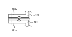
- These three parts are connected by bolt fastening between a flange 120a at the lower end of the peripheral wall of the upper cap part 120 and a flange 121a at the upper end of the peripheral wall of the central body part 121, and a lower end of the peripheral wall of the central body part 121.
- This is done by bolt connection between the flange 121b of the bottom base part 122 and the flange 122a of the outer edge side of the bottom base part 122. Therefore, when those bolts are released, the saturation tank main body 102 is disassembled into three parts.
- the humidity control gas generator 101 When the humidity control gas generator 101 is in operation, water is filled inside the saturation tank main body 102, leaving an area above where the gas should exist.
- the water filled in the saturation tank body 102 is ultrapure water.
- the area filled with water in the saturation tank main body 102 will be referred to as a storage area W, and the upper gas area will be referred to as a gas area G hereinafter.
- the height dimensions of the upper cap part 120 and the central body part 21 of the saturation tank main body 102 are selected so as to satisfy the following conditions. That is, the water surface is located at a height of approximately the upper half of the central body portion 121 and never reaches the upper cap portion 120, so that the inside of the upper cap portion 120 always corresponds to the gas region G.
- a gas heater (heating section) 105 for heating the gas in the gas region G is provided on the outer surface of the peripheral wall of the upper cap section 120 of the saturation tank main body 102. Most of the outer surface of the upper cap part 120 may be covered with the gas heater 105.
- a water heater 106 for heating the water in the storage area W is disposed at a lower portion inside the saturation tank main body 102, for example, at a height position close to the bottom base portion 122.
- the heater may be arranged on the wall of the saturation tank main body 102, for example, on the outer surface of the peripheral wall of the central body portion 121.
- a water heater/cooler capable of heating and cooling water such as a heat pump utilizing the Peltier effect, may be in close contact with the outer surface of the wall of the saturation tank body 102.
- a gas introduction path 122b is formed within the wall of the bottom base portion 122 of the saturation tank main body 102.
- a gas inlet 122c of the gas introduction path 122b opens to the outer surface of the wall of the bottom base portion 122, and a gas outlet 122d thereof opens toward the storage area W of the wall of the bottom base portion 122.
- a porous body 107 is provided at the gas outlet 122d to form fine bubbles B of the gas released from there into the storage area W.
- a reserve water tank 103 is arranged outside the saturation tank main body 102.
- Reserve water tank 103 has an upper part 130 and a lower part 131. These two parts are joined together to form the reserve water tank 103 in such a manner that the upper surface of the wall of the lower part 131 is in close contact with the lower end surface of the peripheral wall of the upper part 130.
- the connection between these two parts is made by a bolt connection between a flange 130a at the lower end of the peripheral wall of the upper part 130 and a flange 131a on the outer edge side of the lower part 131. Therefore, by releasing those bolts, the reserve water tank 103 can be disassembled into two parts.
- the main material of the reserve water tank 103 is a highly durable metal, such as stainless steel.
- An opening 130b is provided in the wall of the upper part 130 of the reserve water tank 103, for example, the ceiling wall, and an opening 120b is provided in the upper wall of the upper cap part 120 of the saturation tank main body 102. They are connected through a communication pipe 108. Further, an opening 131b is provided in the wall of the lower part 31 of the reserve water tank 103, for example, the bottom wall, and an opening 121c is provided in the lower wall of the saturation tank main body 102, for example, the lower circumferential wall of the central body 121. , both openings 131b and 121c are connected by a water communication pipe 109.
- the height dimension of the reserve water tank 103 and the height of its arrangement relative to the saturation tank main body 102 are selected so as to satisfy the following conditions. That is, the height of the water surface falls within the internal height dimension of the reserve water tank 103. Therefore, the water surface height inside the reserve water tank 103 and the water surface height inside the saturation tank main body 102 are equal, and the gas area G and the storage area W also exist inside the reserve water tank 103.
- the inside of the reserve water tank 103 and the inside of the saturation tank main body 102 communicate with each other through both the gas area G and the storage area W. Therefore, when water is consumed and reduced inside the saturation tank main body 102, water is replenished from the reserve water tank 103 into the saturation tank main body 102.
- Another opening 130c is provided in the wall of the reserve water tank 103, and the water supply pipe 110 is connected to the opening 130c. If the water level in the saturation tank falls too low, water can be manually or automatically replenished into the reserve water tank 103 from the water supply pipe 110.
- a gas reflux device 104 is arranged inside the saturation tank main body 102.
- the gas recirculation device 104 includes a gas return pipe 140, a gas delivery pipe 141, a drain pipe 142, and a trap box 143.
- the main material of the gas reflux device 104 is a highly durable metal, such as stainless steel.
- the gas return pipe 140 has a substantially linear shape and is arranged vertically, for example, substantially vertically, and has a gas inlet 140a at its upper end and a gas outlet 140b at its lower end.
- the gas inlet 140a of the gas return pipe 140 is arranged at the upper part of the gas region G in the saturation tank main body 102, for example, at a position close to the ceiling wall of the upper cap part 120.
- the gas return pipe 140 passes from the gas inlet 140a in the gas area G, passes through the storage area W, and reaches the gas outlet 140b inside the trap box 143.
- the gas outlet 140b of the gas return pipe 140 is arranged at a position lower than the uppermost position inside the trap box 143, for example, at a position lowered by a predetermined distance from the top wall of the trap box 143.
- a portion of the gas return pipe 140 near the gas outlet 140b is bent obliquely with respect to the vertical direction and reaches the gas outlet 140b (see FIG. 4).
- the direction of the gas outlet 140b in the horizontal plane is different from the direction in which the gas inlet 141a of the gas delivery pipe 141 exists in the horizontal plane as seen from the gas outlet 140b. Therefore, the gas flow blown out from the gas outlet 140b heads in a different direction from the gas inlet 141a of the gas delivery pipe 41.
- the front end surface 140c of the gas outlet 140b of the gas return pipe 140 is approximately circular, but the front end surface 140c is tilted diagonally so that at least a portion of the circular end surface contacts the inner surface of the trap box 143. It has been cut. More specifically, the gas outlet 140b is disposed near the inner surface of the inner wall of the trap box 143, faces toward the inner surface of the wall, and is located at a portion of the gas outlet 140b (for example, the most distal portion of the gas outlet 140b). (extended tip) is in contact with the inner surface of the trap box 143.
- the central axis of the gas return pipe 140 at the gas outlet 140b of the gas return pipe 140 is inclined in the circumferential direction with respect to the inner surface of the inner wall of the trap box 143.
- a gas temperature sensor 111 that detects the temperature of the gas is arranged in the gas region G at approximately the same height as the gas inlet 140a of the gas return pipe 140.
- a detection signal from the gas temperature sensor 111 is input to a control device (not shown) disposed outside the saturation tank main body 102, and is used for gas temperature control by the gas heater.
- the gas delivery pipe 141 has a curved shape, for example, an inverted L shape, is arranged vertically, has a gas inlet 141a at the lower end of the almost vertical part, and has a gas inlet 141a at the lower end of the almost horizontal part. It has a gas outlet 141b at the upper end.
- the gas inlet 141a of the gas delivery pipe 141 is arranged at a higher position than the gas outlet 140b of the gas return pipe 40 inside the trap box 143.
- the gas delivery pipe 141 extends upward from the gas inlet 141a, exits the trap box 143, enters the storage area W, changes direction almost horizontally, and then extends below the water level on the wall of the central body 121. It penetrates through this point and reaches the gas delivery port 141b arranged outside the saturation tank main body 102.
- a water temperature sensor 112 that detects the temperature of water is arranged at approximately the same height as the gas delivery pipe 141 in the storage area W.
- a detection signal from the water temperature sensor 112 is input to a control device (not shown) disposed outside the saturation tank main body 102 and is used to control the water temperature by the water heater 106.
- the drain pipe 142 has a water inlet 142a located almost at the bottom inside the trap box 143, and a water outlet 142b located outside the saturation tank body 102.
- the drain pipe 142 extends from the water inlet 142a, exits the trap box 143, penetrates the wall of the central body 121, and exits the saturation tank body 102.
- the trap box 143 is arranged within the storage area W in the central body 121 of the saturation tank main body 102 at a higher height than the water heater 106 described above.
- the horizontal cross-sectional area of the trap box 143 is larger than the horizontal cross-sectional area of the gas return pipe 140, and within the trap box 143, the gas outlet 140b of the gas return pipe 140 and the gas inlet 140a of the gas delivery pipe 141 are They are arranged a predetermined distance apart in the horizontal direction. As described above, within the trap box 143, the gas outlet 140b of the gas return pipe 140 faces in a direction different from the direction in which the gas inlet 140a of the gas delivery pipe 141 is viewed from the gas outlet 140b.
- the trap box 143 has a height greater than a predetermined value, and the gas outlet 140b of the gas return pipe 140 is disposed at a lower position than the gas inlet 140a of the gas delivery pipe 141 within the trap box 143. Furthermore, inside the trap box 143, the gas inlet 141a of the gas delivery pipe 141 is arranged at a high position that is a predetermined height away from the bottom surface of the trap box 143 where water collects.
- the entire inner surface of the saturation tank main body 102 in contact with the gas region G and storage region W is made of a corrosion-resistant material that has higher durability against pure water than the main material of the saturation tank main body 102, such as stainless steel, such as a fluororesin (such as Teflon (registered)). Trademark)), coated with a layer of.
- a corrosion-resistant material that has higher durability against pure water than the main material of the saturation tank main body 102, such as stainless steel, such as a fluororesin (such as Teflon (registered)). Trademark)
- the mutual contact surfaces between the upper cap portion 120 and the center body portion 121 of the saturation tank body 102 (the contact surfaces facing each other between the flanges 120a and 121a), and the contact surfaces between the center body portion 121 and the bottom
- the mutual contact surfaces of the base portion 122 are also coated with a layer of the same corrosion-resistant material.
- the inner surface of the reserve water tank 103 in contact with the gas region G and storage region W is also coated with a layer of the same corrosion-resistant material.
- the mutual contact surfaces of the upper part 130 and lower part 131 of the reserve water tank 103 are also coated with the same layer of corrosion-resistant material.
- the outer surface of the gas recirculation device 104 in contact with the gas region G and storage region W (for example, the outer surface of the trap box 43) is also coated with a layer of the same corrosion-resistant material.
- the humidity-controlled gas generator 101 of the present embodiment described above has better water resistance, maintainability, cleanliness of the output gas, or controllability of the humidity of the output gas than conventional humidity-controlled gas generators. It can be expected to be superior to conventional humidity control gas generators.
- the humidity control gas generator 101 of this embodiment can be suitably used in a dry cleaning process in a semiconductor manufacturing process, and can also be used in other semiconductor manufacturing processes, such as humidity control in a stepper in an exposure process, a spin coater, etc. It can also be suitably used for controlling the humidity of the atmosphere during the painting process.
- FIG. 5 shows a modification of the humidity control gas generator 101.
- a water stirring device 150 is added to the saturation tank main body 102 having the same configuration as shown in FIG.
- the water stirring device 150 stirs the water in the saturation tank main body 102 by sucking water from the upper part of the saturation tank main body 102 and returning it to the lower part of the saturation tank main body 102 using a pump. This makes the temperature of the water in the saturation tank body 102 more uniform throughout.
- the flow rate of gas supplied into the saturation tank main body 102 from the gas introduction path 122b is large to a certain extent, the bubbles B stir the water in the saturation tank main body 102 to some extent, so the water stirring device is not necessarily driven. You don't have to.
- the water stirring effect by the bubbles B becomes slight, and stirring the water in the saturation tank main body 102 with the water stirring device will reduce the temperature of the water and the output gas. is preferable for controlling the temperature to a target value.
- the present invention is not limited to the above-described embodiments, and includes various modifications.
- the embodiments described above are described in detail to explain the present invention in an easy-to-understand manner, and the present invention is not necessarily limited to having all the configurations described.
- it is possible to replace a part of the configuration of one embodiment with the configuration of another embodiment and it is also possible to add the configuration of another embodiment to the configuration of one embodiment.
Landscapes
- General Physics & Mathematics (AREA)
- Engineering & Computer Science (AREA)
- Physics & Mathematics (AREA)
- Immunology (AREA)
- Health & Medical Sciences (AREA)
- Biochemistry (AREA)
- General Health & Medical Sciences (AREA)
- Chemical & Material Sciences (AREA)
- Life Sciences & Earth Sciences (AREA)
- Pathology (AREA)
- Analytical Chemistry (AREA)
- Condensed Matter Physics & Semiconductors (AREA)
- Manufacturing & Machinery (AREA)
- Computer Hardware Design (AREA)
- Microelectronics & Electronic Packaging (AREA)
- Power Engineering (AREA)
- Control Of Non-Electrical Variables (AREA)
Abstract
チャンバ内の温度及び湿度を高精度に制御することが可能な温湿度制御装置、及び、温湿度制御装置と調湿ガス発生装置との組合せを提供する。 温湿度制御装置1は、チャンバCを画成する容器2と、容器2を包囲する底壁31と天壁32と側壁33とを有し、容器2が底壁31、天壁32及び側壁33から間隔を置いた位置に配置され、容器2と底壁31、天壁32及び側壁33との間の空間に熱媒液を収容して容器2の外面全域を液没可能に構成された水槽3と、水槽3内の熱媒液の温度を制御する温度制御装置5と、温度制御装置5により温度制御された熱媒液を水槽3内に供給し、且つ、水槽3内の熱媒液を温度制御装置5に戻すようにして熱媒液を循環させる循環装置5と、チャンバC内に開いたガス出口を有し、湿度が所定値に調整された調湿ガスを容器2のチャンバC内に導入するガス導入管6とを備える。
Description
本発明は、温湿度制御装置、及び、温湿度制御装置と調湿ガス発生装置との組合せに関する。
特許文献1は、湿度雰囲気用熱機械分析装置を開示する。その開示によると、保温チャンバが、所定温度の熱媒体が循環する恒温ジャケットの内側に形成されている。保温チャンバの給気ポートおよび排気ポートに通じる給気管および排気管は、それぞれ恒温ジャケット内を通過している。
このような構成により、保温チャンバ内に導入された雰囲気ガスの温度及び湿度の安定化を図っている。
しかし、特許文献1に開示された装置では、保温チャンバの全周囲が恒温ジャケットに覆われていない。このため、保温チャンバ内に導入された雰囲気ガスの温度及び湿度を高精度に制御することができない。
本発明の目的は、チャンバ内の温度及び湿度を高精度に制御することが可能な温湿度制御装置、及び、温湿度制御装置と調湿ガス発生装置との組合せを提供することにある。
一実施形態に従う温湿度制御装置は、チャンバを画成する容器と、容器を包囲する底壁と天壁と側壁とを有し、容器が底壁、天壁及び側壁から間隔を置いた位置に配置され、容器と底壁、天壁及び側壁との間の空間に熱媒液を収容して容器の外面全域を液没可能に構成された水槽と、水槽内の熱媒液の温度を制御する温度制御装置と、温度制御装置により温度制御された熱媒液を水槽内に供給し、且つ、水槽内の熱媒液を温度制御装置に戻すようにして熱媒液を循環させる循環装置と、チャンバ内に開いたガス出口を有し、湿度が所定値に調整された調湿ガスを容器のチャンバに導入するガス導入管と、を備える。
水槽内に配置され且つ容器を収容する内水槽をさらに備え、内水槽は、底板と側板と上部開口とを有し、容器が底板及び側板から間隔を置いた位置に配置され、空間を内水槽の内側にある内空間と内水槽の外側にある外空間とに分け、水槽内に供給された熱媒液は、内空間から外空間へと、内水槽の上部開口を通って流れるように構成され、循環装置からの熱媒液の供給口が内水槽内の内空間の底部に配置され、水槽からの熱媒液の出口が水槽内の外空間の底部に配置されていてもよい。
ガス導入管は、容器から空間を通って水槽外へ延出し、ガス導入管の空間内に存在する部分は、部分内を流れる調湿ガスと空間内の熱媒液との間の熱交換のための熱交換器を形成してもよい。
内水槽は、平面視で円形、矩形、又は楕円形であり、循環装置からの熱媒液の供給口は、内水槽内の内空間の底部に複数配置され、複数の供給口は、平面視で内水槽の中心に対し対象な位置に配置されていてもよい。
容器の容量は、500mL以上であり、好ましくは1.0Lであり、より好ましくは5.0L以上であってもよい。
一実施形態に従う温湿度制御装置と調湿ガス発生装置との組合せは、上記の温湿度制御装置と上記の温湿度制御装置に調湿ガスを供給する調湿ガス発生装置とを備える。調湿ガス発生装置は、ガス域と前記ガス域の下方にある貯水域とを内部に有する飽和槽本体と、前記飽和槽本体の内部に配置されたガス還流装置とを有する。ガス還流装置は、ガス戻り管と、ガス送出管と、排水管と、トラップ箱を有する。ガス戻り管は、ガス域内に配置されたガス入口から貯水域内を通過してトラップ箱内に配置されたガス出口に至る。ガス送出管は、トラップ箱内に配置されたガス送入口から飽和槽本体の外部に配置されたガス送出口に至る。排水管は、トラップ箱内に配置された水入口から飽和槽本体の外部に配置された水出口に至る。
本発明は、チャンバ内の温度及び湿度を高精度に制御することが可能な温湿度制御装置、及び、温湿度制御装置と調湿ガス発生装置との組合せを提供することができる。
以下、本発明の実施形態について、図面を参照して説明する。なお、以下に説明する実施形態は請求の範囲に係る発明を限定するものではなく、また実施形態の中で説明されている諸要素及びその組み合わせの全てが発明の解決手段に必須であるとは限らない。
図1は、一実施形態に係る温湿度制御装置1と調湿ガス発生装置101との組合せの図であり、主に温湿度制御装置1の縦断面図を示している。調湿ガス発生装置101は、湿度が所定値に調整されたガスを発生する装置であり、当該ガスを温湿度制御装置1へ供給する。
図1に示されるように、一実施形態にかかる温湿度制御装置1は、装置本体10と、温度制御・循環装置5とを備える。装置本体10は、容器2と、水槽3と、内水槽4と、ガス導入管6とを備える。
容器2は、全体としてほぼ円筒又は多角筒(例えば正方筒)の形状を有する。容器2は、容器本体21と、蓋部22とを有する。蓋部22が容器本体21の上部開口を覆うことにより、容器2の内部にチャンバCが画成される。蓋部22を容器本体21に密着させて固定した状態では、チャンバCへの液体の浸入が阻止されるように構成されている。チャンバC内には、複数の試料23が設置される。容器2の容量は、例えば、500mL以上であり、好ましくは1.0Lであり、より好ましくは5.0L以上である。容器2を構成する部品の主材料は、耐久性の高い金属、例えばステンレススティールである。なお、容器2の容量は、上記の容量に限らず500mL未満でもあってもよい。
水槽3は、全体としてほぼ円筒又は多角筒(例えば正方筒)の形状を有する。水槽3は、底壁31と、天壁32と、側壁33とを有する。底壁31、天壁32、及び側壁33は、容器2を包囲している。容器2は、底壁31、天壁32、及び側壁33から間隔を置いた位置に配置されている。温湿度制御装置1の作動時には、容器2と、底壁31、天壁32、及び側壁33との間の空間Sに、上部に大気空間を残して、水、冷却剤水溶液等の熱媒液が充填される。熱媒液により、容器2の外面全域は液没する。このため、チャンバC内のガスの温度及び湿度を高精度に制御することができる。水槽3を構成する部品の主材料は、耐久性の高い金属、例えばステンレススティールである。
内水槽4は、全体としてほぼ円筒又は多角筒(例えば正方筒)の形状を有する。内水槽4は、水槽3内に配置され、容器2を収容する。内水槽4は、底板41と側板42と上部開口43とを有する。底板41及び側板42は、それぞれ底壁31及び側壁33から間隔を置いた位置に配置されている。容器2は、底板41及び側板42から間隔を置いた位置に配置されている。内水槽4は、空間Sを、内水槽4の内側にある内空間S1と内水槽4の外側にある外空間S2とに分割する。温湿度制御装置1の作動時には、水槽3内に供給される熱媒液は、内空間S1から外空間S2へと、内水槽4の上部開口43を通って流れる。内水槽4の内において、容器2の外面全域は熱媒液により液没する。よって、温湿度制御装置1の作動時に、容器2は、熱媒液の内側ジャケット及び熱媒液の外側ジャケットにより覆われる。このため、容器2と熱媒液の熱交換が促進され、チャンバC内のガスの温度及び湿度をより高精度に制御することができる。
温度制御・循環装置5は、装置本体10の外部に設けられている。温度制御・循環装置5は、温度制御装置及び循環装置を有する。温度制御装置は、加熱手段及び冷却手段を有し、熱冷媒を例えば5~55℃の範囲で制御可能である。循環装置は、ポンプを有し、温度制御部で制御された所望の温度の熱媒液を水槽3内に供給し、且つ、水槽3内の熱媒液を温度制御・循環装置5に戻すようにして熱媒液を循環させる。
温度制御・循環装置5と、水槽3及び内水槽4とは、液供給管51及び液戻り管52により接続されている。液供給管51及び液戻り管52は、装置本体10内に設けられている。液供給管51は途中で複数に分岐しており、分岐管53にはそれぞれ流量計54が設けられている。温湿度制御装置1の作動時には、各流量計54の測定結果に基づき、各分岐管53を流れる熱媒液の量が等しくなるように制御される。
液供給管51(分岐管53)の出口である内水槽4への熱媒液の複数の供給口55は、内水槽4内の内空間S1の底部に配置されている。液戻り管52の入口である水槽3からの熱媒液の出口56が水槽3内の外空間S2の底部に配置されている。内水槽4は、平面視で円形、矩形、又は楕円形である。複数の供給口55は、平面視で内水槽4の中心に対し対象な位置に配置されている。これにより、容器2の外周に対し均等に熱媒液を流すことができ、温度制御の精度を上げることができる。なお、複数の供給口55は、本実施形態では2つであるが、3つ以上であってもよく、供給口55の数に合わせて分岐管53の数も増加する。
ガス導入管6は、容器2から空間S(内空間S1及び外空間S2)を通って水槽3外へ延出している。ガス導入管6の外空間S2内に存在する途中部分61は、直線状ではなく、螺旋形状をなしている。温湿度制御装置1の作動時には、当該途中部分61内を流れる調湿ガスと外空間S2内の熱媒液との間で熱交換が行われる。よって、途中部分61は熱交換器として機能する。このため、途中部分61を通過するガスの温度が所望温度に近づくので、いっそう温度制御の精度が上がる。
ガス導入管6の水槽3外の端部には、フレキシブルホース62が接続されている。フレキシブルホース62の周囲には図示せぬヒータが設けられている。当該ヒータは、フレキシブルホース62内を流れる調湿ガスが結露するのを防止するために設けられている。フレキシブルホース62のガス導入管6とは反対側の端部は、調湿ガス発生装置101に接続される。具体的には、フレキシブルホース62は、後述のガス還流装置104のガス送出管141に接続される(図2参照)。温湿度制御装置1の作動時には、調湿ガス発生装置101からの湿度が所定値に調整された調湿ガスが、ガス導入管6をチャンバC内に開いたガス出口63を介してチャンバCに導入される。
容器2の蓋部22には、複数のダクト7が設けられている。複数のダクト7は、蓋部22から上方へ延び、水槽3を貫通し、水槽3の外部まで延びている。複数のダクト7は、チャンバC内へセンサを挿入するため及びチャンバCのガスを排気するためのダクトである。複数のダクト7を介して、温度センサ71、湿度センサ72、及び変位計・ロードセル73がチャンバC内へ挿入される。温度センサ71は、チャンバC内の温度を測定する。湿度センサ72は、チャンバC内の湿度を測定する。温度センサ71及び湿度センサ72の検出信号は図示しない制御装置に入力されて、温度制御・循環装置5による熱媒液の温度制御に利用される。変位計・ロードセル73は、チャンバC内に配置された試料23に掛る荷重及び試料23の変位を測定する。水槽3の外部には、装置本体10内の環境温度をモニターするための環境温度センサ74が設けられている。
温湿度制御装置1は、液位調節装置8をさらに備える。液位調節装置8は、液収容容器81と、供給管82と、排出管83と、2つのポンプ84、85と、チェックバルブ86と、バルブ87とを有する。液収容容器81の容量は、例えば20Lである。供給管82は、内水槽4から外空間S2を通って水槽3外へ延出し、液収容容器81の下部まで延びている。排出管83は、内水槽4から外空間S2を通って水槽3外へ延出し、液収容容器81の上部まで延びている。供給管82には、ポンプ84及びチェックバルブ86が設けられている。排出管83には、ポンプ85及びバルブ87が設けられている。液収容容器81には、給排気管88及びフィルタ89が設けられている。
試験終了後に液位調節装置8のポンプ85により、内水槽4から熱媒液が液収容容器81へ排出される。内水槽4内の液位が蓋部22よりも下側になるまで、液位調節装置8により熱媒液が排出される。その後、蓋部22が開けられ、容器2から試料23が取り出され、次に試験を行う試料23が容器2内に配置される。試料23を配置した後、蓋部22が閉じられ、液位調節装置8のポンプ84により、液収容容器81内の熱媒液が内水槽4へ供給される。このように、液位調節装置8により、内水槽4の熱媒液の液位の高さが調節される。
温湿度制御装置1は、2つの排水管9をさらに備える。各排水管9にはバルブ9Aが設けられている。各バルブ9Aを開放することにより、水槽3及び内水槽4から熱媒液が各排水管9を介して外部に排出される。
水槽3、液供給管51、液戻り管52、ガス導入管6、フレキシブルホース62、供給管82、及び排出管83の周囲は全て断熱材により覆われている。
以上説明した本実施形態の温湿度制御装置1によれば、チャンバC内の温度及び湿度を高精度に制御すること可能である。
次に、調湿ガス発生装置101について説明する。
図2は、一実施形態に係る調湿ガス発生装置101の縦断面図である。
一実施形態にかかる調湿ガス発生装置101は、飽和槽本体102と、予備水タンク103と、ガス還流装置104とを備える。
飽和槽本体102は、全体として上下に細長いほぼ円筒又は多角筒(例えば正方筒)の形状を有する。飽和槽本体102は、上側キャップ部120と、中央胴部121と、底ベース部122との3つの部品から構成される。飽和槽本体102のこれら部品の主材料は、耐久性の高い金属、例えばステンレススティールである。
上側キャップ部120の周壁の下端面に中央胴部121の周壁の上端面が密着し、中央胴部121の周壁の下端面に底ベース部122の中央部の上面が密着する態様で、これら3つの部品が順次に結合されて、飽和槽本体102が形成される。これら3つの部品間の結合は、上側キャップ部120の周壁の下端部のフランジ120aと中央胴部121の周壁の上端部のフランジ121aとの間のボルト締結と、中央胴部121の周壁の下端部のフランジ121bと底ベース部122の外縁側のフランジ122aとの間のボルト結合によりなされる。従って、それらのボルト締結を解除すれば、飽和槽本体102は3つの部品に分解される。
調湿ガス発生装置101の作動時には、飽和槽本体102の内部に、その上部のガスが存在すべき領域を残して、水が充填される。調湿ガス発生装置101がシリコンウェハのドライ洗浄に利用される場合、飽和槽本体102に充填される水は超純水である。飽和槽本体102内の水が充填された領域を以下、貯水域Wといい、上部のガスの領域を以下、ガス域Gという。
飽和槽本体102の上側キャップ部120と中央胴部21との高さ寸法は、次の条件を満たすように選ばれる。すなわち、水面は中央胴部121のほぼ上側半分の高さ領域にあって、上側キャップ部120に到達することはなく、よって、常に上側キャップ部120の内部はガス域Gに該当する。
飽和槽本体102の上側キャップ部120の周壁の外表面にガス域G内のガスを加熱するためのガスヒータ(加温部)105が設けられる。上側キャップ部120は、その外表面の大部分がガスヒータ105でおおわれていてよい。
飽和槽本体102の内部の下部、例えば、底ベース部122に近い高さ位置に、貯水域Wの水を加熱するための水ヒータ106が配置される。なお、ヒータは、飽和槽本体102の壁、例えば中央胴部121の周壁の外面に配置されてもよい。水ヒータ106に代えて、水の過熱と冷却を行える水ヒータ・クーラ、例えばペルチェ効果を利用したヒートポンプが、飽和槽本体102の壁の外表面に密着していてもよい。
飽和槽本体102の底ベース部122の壁内には、ガス導入路122bが形成される。ガス導入路122bのガス入口122cは底ベース部122の壁の外表面に開口し、そのガス出口122dは底ベース部122の壁の貯水域Wに向けて開口する。そのガス出口122dには、そこから貯水域Wに放出されるガスを微細な気泡Bにするための多孔体107が設けられる。
飽和槽本体102の外部に、予備水タンク103が配置される。予備水タンク103は、上側部130と下側部131とを有する。上側部130の周壁の下端面に下側部131の壁の上面が密着する態様で、これら2つの部品が結合されて、予備水タンク103が形成される。これら2つの部品間の結合は、上側部130の周壁の下端部のフランジ130aと下側部131の外縁側のフランジ131aとの間のボルト結合によりなされる。従って、それらのボルト締結を解除すれば予備水タンク103は2つの部品に分解され得る。
予備水タンク103の主材料は、耐久性の高い金属、例えばステンレススティールである。
予備水タンク103の上側部130の壁、例えば天壁、に開口130bが設けられ、飽和槽本体102の上側キャップ部120の上部の壁にも開口120bが設けられ、両開口130b、120bがガス連通管108で接続される。また、予備水タンク103の下側部31の壁、例えば底壁に開口131bが設けられ、飽和槽本体102の下部の壁、例えば中央胴部121の下部の周壁、にも開口121cが設けられ、両開口131b、121cが水連通管109で接続される。
予備水タンク103の高さ寸法と飽和槽本体102に対する配置の高さは、次の条件を満たすように選ばれる。すなわち、その水面の高さは予備水タンク103の内部の高さ寸法内に収まる。したがって、予備水タンク103の内部の水面高さと飽和槽本体102内の水面高さは等しく、予備水タンク103の内部にも同様に、ガス域Gと貯水域Wとが存在する。
このように、予備水タンク103の内部と飽和槽本体102の内部はガス域Gと貯水域Wの両方で連通している。したがって、飽和槽本体102内部で水が消費されて減ったならば、予備水タンク103から飽和槽本体102内部へ水が補充される。
予備水タンク103の壁には、別の開口130cが設けられており、その開口130cには給水管110が接続される。飽和槽内の水位が下がりすぎた場合、給水管110から予備水タンク103内に、手動または自動で水を補給することができる。
飽和槽本体102の内部に、ガス還流装置104が配置される。ガス還流装置104は、ガス戻り管140と、ガス送出管141と、排水管142と、トラップ箱143とを備える。ガス還流装置装置104の主材料は、耐久性の高い金属、例えばステンレススティールである。
ガス戻り管140は、ほぼ直線的な形状で上下方向、例えばほぼ垂直、に配置され、その上端にガス入口140a、下端にガス出口140bをもつ。ガス戻り管140のガス入口140aは、飽和槽本体102内のガス域Gの上部、例えば、上側キャップ部120の天壁に近い位置に配置される。ガス戻り管140はガス域G内のガス入口140aから貯水域W内を通過してトラップ箱143の内部のガス出口140bに至る。
ガス戻り管140のガス出口140bは、トラップ箱143の内部の最上位置より低い位置、例えば、トラップ箱143の天壁から所定距離だけ下がった位置、に配置される。ガス戻り管140のガス出口140bの近傍部分は、垂直に対して斜めに傾斜するように曲がってガス出口140bに至る(図4参照)。そして、ガス出口140bの水平面での向きは、そのガス出口140bから見た水平面でのガス送出管141のガス送入口141aの存在する方向とは異なる方向である。よって、ガス出口140bから吹き出るガス流は、ガス送出管41のガス送入口141aとは異なる方向に向かう。
また、図4に示すように、ガス戻り管140のガス出口140bの前端面140cはほぼ円形であるが、その円形の端面の少なくとも一部がトラップ箱143の内面に接するように、斜め方向にカットされている。より詳細には、ガス出口140bはトラップ箱143の内壁の内面の近傍に配置され、その壁の内面に向いており、かつ、ガス出口140bの一部分(例えば、ガス出口140bの中で最も先方に延びた先端部)がトラップ箱143の内面に接触している。
以上の構成により、ガスがガス戻り管140内を通る間に凝縮した水がガス出口140bから出てトラップ箱143内に落下するとき、それがガス出口140bから吹き出るガス流に運ばれてガス送出管141のガス入口140aに入り込んでしまう問題が低減される。
また、図4に示すように、ガス戻り管140のガス出口140bにおけるガス戻り管140の中心軸は、トラップ箱143の内壁の内面に対して周方向へ傾斜した向きになっている。
ガス域G内のガス戻り管140のガス入口140aとほぼ同じ高さに、ガスの温度を検出するガス温度センサ111が配置される。このガス温度センサ111の検出信号は、飽和槽本体102の外部に配置された図示しない制御装置に入力されて、ガスヒータによるガス温度制御に利用される。
ガス送出管141は、例えば逆L字型に曲がった形状もち、上下方向に配置されて、そのほぼ垂直に立った部分の下端にガス送入口141aをもち、そのほぼ水平に配された部分の上端にガス送出口141bをもつ。
ガス送出管141のガス送入口141aは、トラップ箱143の内部のガス戻り管40のガス出口140bより高い位置に配置される。ガス送出管141は、ガス送入口141aから上に伸びてトラップ箱143の外へ出て貯水域W内に入り、そこでほぼ水平に向きを変えてから、中央胴部121の壁の水面より下方の個所を貫通して、飽和槽本体102の外部に配置されたガス送出口141bに至る。
貯水域W内のガス送出管141とほぼ同じ高さに、水の温度を検出する水温センサ112が配置される。この水温センサ112の検出信号は、飽和槽本体102の外部に配置された図示しない制御装置に入力されて、水ヒータ106による水の温度制御に利用される。
排水管142は、トラップ箱143の内部のほぼ最下部に配置された水入口142aと、飽和槽本体102の外部に配置された水出口142bとをもつ。排水管142は、水入口142aから伸びてトラップ箱143の外へ出て、中央胴部121の壁を貫通して飽和槽本体102の外部へ出る。
トラップ箱143は、飽和槽本体102の中央胴部121内の貯水域W内であって、前述した水ヒータ106より高い高さの位置に、配置される。
図4に示すように、トラップ箱143の水平断面積は、ガス戻り管140の水平断面積より大きく、トラップ箱143内でガス戻り管140のガス出口140bとガス送出管141のガス入口140aは水平方向において所定距離だけ離れて配置される。そして、前述したようにトラップ箱143内では、ガス戻り管140のガス出口140bが、そのガス出口140bからガス送出管141のガス入口140aを見た方向とは異なる方向を向く。さらに、トラップ箱143は所定値以上の高さ寸法を有し、トラップ箱143内でガス戻り管140のガス出口140bは、ガス送出管141のガス入口140aより低い位置に配置される。またさらに、トラップ箱143の内部で、水が溜まることになるトラップ箱143の底面から所定高さだけ離れた高い位置に、ガス送出管141のガス送入口141aが配置される。
飽和槽本体102のガス域Gと貯水域Wに接する内表面の全面は、純水に対する耐久が飽和槽本体102の主材料、例えばステンレススティールよりより高い耐食性材料、例えばフッ素樹脂(例えばテフロン(登録商標))、の層でコートされる。図3に示すように、飽和槽本体102の上側キャップ部120と中央胴部121との相互の密着面(双方のフランジ120a、121aの相対向する密着面)、及び、中央胴部121と底ベース部122の相互の密着面(双方のフランジの密着面)も、同じ耐食性材料の層でコートされる。
予備水タンク103のガス域Gと貯水域Wに接する内表面も、同じ耐食性材料の層でコートされる。予備水タンク103の上側部130と下側部131の相互の密着面(双方のフランジ130a、131aの相対向する密着面)も、同じ耐食性材料の層でコートされる。
ガス還流装置104のガス域Gと貯水域Wに接する外表面(例えばトラップ箱43の外表面)も、同じ耐食性材料の層でコートされる。
以上説明した本実施形態の調湿ガス発生装置101は、従来の調湿ガス発生装置に比較して、耐水性、保守管理性、出力ガスのクリーンさ、または出力ガスの湿度の制御性において、従来の調湿ガス発生装置より優れることが期待され得る。
本実施形態の調湿ガス発生装置101は、半導体製造工程のドライ洗浄工程に好適に用いることができ、また、他の半導体製造工程、例えば露光工程におけるステッパ内の雰囲気の調湿、スピンコータなどによる塗装工程における雰囲気の調湿などにも好適に用いることができる。
図5は、調湿ガス発生装置101の変形例を示す。
この変形例では、図2に示したのと同じ構成の飽和槽本体102に、水撹拌装置150が付加される。
水撹拌装置150は、ポンプにより飽和槽本体102内の上部の水を吸入してこれを飽和槽本体102内の下部へ戻すことで、飽和槽本体102内の水を撹拌する。これにより、飽和槽本体102内の水の温度が全体的により均一になる。
因みに、ガス導入路122bから飽和槽本体102内へ供給されるガスの流量が或る程度の多い時は、気泡Bが飽和槽本体102内の水をある程度撹拌するので、必ずしも水撹拌装置を駆動しなくてもよい。しかし、上記供給ガス流量が或る程度より少ない時には、気泡Bによる水の撹拌作用はわずかになるで、水撹拌装置で飽和槽本体102内の水を撹拌することが、水の温度ひいては出力ガスの温度を目標値に制御するのに好ましい。
なお、本発明は上記した実施例に限定されるものではなく、様々な変形例が含まれる。例えば、上記した実施例は本発明を分かりやすく説明するために詳細に説明したものであり、必ずしも説明した全ての構成を備えるものに限定されるものではない。また、ある実施例の構成の一部を他の実施例の構成に置き換えることが可能であり、また、ある実施例の構成に他の実施例の構成を加えることも可能である。また、各実施例の構成の一部について、他の構成の追加・削除・置換をすることが可能である。
また、図示した各構成要素の寸法、形状等は必ずしも正確に図示されているとは限らず、本実施形態の特徴を強調するために適宜修正されていることもありうる。
1…温湿度制御装置 2…容器 3…水槽底壁 31…底壁 32…天壁 33…側壁 4…内水槽 41…底板 42…側板 43…上部開口 5…温度制御・循環装置 55…供給口 56…出口 6…ガス導入管 61…途中部分 63…ガス出口 8…液位調節装置 C…チャンバ S…空間 S1…内空間 S2…外空間
101…調湿ガス発生装置 102…飽和槽本体 103…予備水タンク 104…ガス還流装置 140…ガス戻り管 140a…ガス入口 140b…ガス出口 141…ガス送出管 141a…ガス送入口 141b…ガス送出口 142…排水管 142a…水入口 142b…水出口 143…トラップ箱 G…ガス域 W…貯水域
101…調湿ガス発生装置 102…飽和槽本体 103…予備水タンク 104…ガス還流装置 140…ガス戻り管 140a…ガス入口 140b…ガス出口 141…ガス送出管 141a…ガス送入口 141b…ガス送出口 142…排水管 142a…水入口 142b…水出口 143…トラップ箱 G…ガス域 W…貯水域
Claims (7)
- 前記チャンバを画成する容器と、
前記容器を包囲する底壁と天壁と側壁とを有し、前記容器が前記底壁、前記天壁及び前記側壁から間隔を置いた位置に配置され、前記容器と前記底壁、前記天壁及び前記側壁との間の空間に熱媒液を収容して前記容器の外面全域を液没可能に構成された水槽と、
前記水槽内の熱媒液の温度を制御する温度制御装置と、
前記温度制御装置により温度制御された熱媒液を前記水槽内に供給し、且つ、前記水槽内の熱媒液を前記温度制御装置に戻すようにして熱媒液を循環させる循環装置と、
前記チャンバ内に開いたガス出口を有し、湿度が所定値に調整された調湿ガスを前記容器の前記チャンバに導入するガス導入管と、を備える
温湿度制御装置。 - 前記水槽内に配置され且つ前記容器を収容する内水槽をさらに備え、
前記内水槽は、底板と側板と上部開口とを有し、前記容器が前記底板及び前記側板から間隔を置いた位置に配置され、前記空間を前記内水槽の内側にある内空間と前記内水槽の外側にある外空間とに分け、
前記水槽内に供給された熱媒液は、前記内空間から前記外空間へと、前記内水槽の前記上部開口を通って流れるように構成され、前記循環装置からの熱媒液の供給口が前記内水槽内の前記内空間の底部に配置され、前記水槽からの熱媒液の出口が前記水槽内の前記外空間の底部に配置されている
ことを特徴とする請求項1に記載の温湿度制御装置。 - 前記ガス導入管は、前記容器から前記空間を通って前記水槽外へ延出し、
前記ガス導入管の前記空間内に存在する部分は、前記部分内を流れる調湿ガスと前記空間内の熱媒液との間の熱交換のための熱交換器を形成する
ことを特徴とする請求項1または請求項2に記載の温湿度制御装置。 - 前記内水槽の熱媒液の液位の高さを調節可能な液位調節装置をさらに備える
ことを特徴とする請求項1から請求項3のいずれか一項に記載の温湿度制御装置。 - 前記内水槽は、平面視で円形、矩形、又は楕円形であり、
前記循環装置からの前記熱媒液の供給口は、前記内水槽内の前記内空間の底部に複数配置され、複数の前記供給口は、平面視で前記内水槽の中心に対し対象な位置に配置されている
ことを特徴とする請求項2に記載の温湿度制御装置。 - 前記容器の容量は、500mL以上であり、好ましくは1.0Lであり、より好ましくは5.0L以上である
ことを特徴とする請求項1から請求項5のいずれか一項に記載の温湿度制御装置。 - 請求項1から請求項6のいずれか一項に記載の温湿度制御装置と、前記温湿度制御装置に調湿ガスを供給する調湿ガス発生装置との組合せであって、
前記調湿ガス発生装置は、
ガス域と前記ガス域の下方にある貯水域とを内部に有する飽和槽本体と、
前記飽和槽本体の内部に配置されたガス還流装置と
を有し、
前記ガス還流装置は、ガス戻り管と、ガス送出管と、排水管と、トラップ箱とを有し、
前記ガス戻り管は、前記ガス域内に配置されたガス入口から前記貯水域内を通過して前記トラップ箱内に配置されたガス出口に至り、
前記ガス送出管は、前記トラップ箱内に配置されたガス送入口から前記飽和槽本体の外部に配置されたガス送出口に至り、
前記排水管は、前記トラップ箱内に配置された水入口から前記飽和槽本体の外部に配置された水出口に至る
ことを特徴とする温湿度制御装置と調湿ガス発生装置との組合せ。
Priority Applications (1)
| Application Number | Priority Date | Filing Date | Title |
|---|---|---|---|
| PCT/JP2022/028266 WO2024018573A1 (ja) | 2022-07-20 | 2022-07-20 | 温湿度制御装置、及び、温湿度制御装置と調湿ガス発生装置との組合せ |
Applications Claiming Priority (1)
| Application Number | Priority Date | Filing Date | Title |
|---|---|---|---|
| PCT/JP2022/028266 WO2024018573A1 (ja) | 2022-07-20 | 2022-07-20 | 温湿度制御装置、及び、温湿度制御装置と調湿ガス発生装置との組合せ |
Publications (1)
| Publication Number | Publication Date |
|---|---|
| WO2024018573A1 true WO2024018573A1 (ja) | 2024-01-25 |
Family
ID=89617509
Family Applications (1)
| Application Number | Title | Priority Date | Filing Date |
|---|---|---|---|
| PCT/JP2022/028266 WO2024018573A1 (ja) | 2022-07-20 | 2022-07-20 | 温湿度制御装置、及び、温湿度制御装置と調湿ガス発生装置との組合せ |
Country Status (1)
| Country | Link |
|---|---|
| WO (1) | WO2024018573A1 (ja) |
Citations (3)
| Publication number | Priority date | Publication date | Assignee | Title |
|---|---|---|---|---|
| JP2010159987A (ja) * | 2009-01-06 | 2010-07-22 | Hitachi High-Technologies Corp | 自動分析装置 |
| JP2011163585A (ja) * | 2010-02-05 | 2011-08-25 | Espec Corp | 恒温恒湿装置 |
| WO2021033260A1 (ja) * | 2019-08-20 | 2021-02-25 | マイクロ・イクイップメント株式会社 | 調湿ガス発生装置 |
-
2022
- 2022-07-20 WO PCT/JP2022/028266 patent/WO2024018573A1/ja unknown
Patent Citations (3)
| Publication number | Priority date | Publication date | Assignee | Title |
|---|---|---|---|---|
| JP2010159987A (ja) * | 2009-01-06 | 2010-07-22 | Hitachi High-Technologies Corp | 自動分析装置 |
| JP2011163585A (ja) * | 2010-02-05 | 2011-08-25 | Espec Corp | 恒温恒湿装置 |
| WO2021033260A1 (ja) * | 2019-08-20 | 2021-02-25 | マイクロ・イクイップメント株式会社 | 調湿ガス発生装置 |
Similar Documents
| Publication | Publication Date | Title |
|---|---|---|
| US7765868B2 (en) | Climate chamber for microscopes | |
| US20130133703A1 (en) | Vaporized material supply apparatus, substrate processing apparatus having same and vaporized material supply method | |
| WO2024018573A1 (ja) | 温湿度制御装置、及び、温湿度制御装置と調湿ガス発生装置との組合せ | |
| US20230132065A1 (en) | Incubator | |
| US10876750B2 (en) | Humidifier and method for conditioning air | |
| JP2001340800A (ja) | 塗布装置 | |
| KR102224227B1 (ko) | 반도체 제조설비용 진공칠러탱크 | |
| JPS59145484A (ja) | 復水器 | |
| CN218847792U (zh) | 一种载玻片放置加热装置 | |
| WO2021033260A1 (ja) | 調湿ガス発生装置 | |
| JPH0428350B2 (ja) | ||
| CN112448003A (zh) | 加湿装置及测试系统 | |
| US20110120214A1 (en) | Transdermal diffusion cell testing vessel and methods using same | |
| JP2975601B1 (ja) | ガスを中心とした環境試験槽 | |
| CN213936273U (zh) | 加湿装置及测试系统 | |
| JP6858536B2 (ja) | 加湿器 | |
| JPH11243780A (ja) | 切り花保存装置 | |
| JP7081851B1 (ja) | 環境試験機および環境試験機の試験槽の加熱方法 | |
| KR100812075B1 (ko) | 응축수 부식 시험장치 | |
| JP4813944B2 (ja) | 飽和ガス供給装置 | |
| JPH0249457B2 (ja) | ||
| JP2010075870A (ja) | 理化学試験用恒温装置 | |
| RU2730945C1 (ru) | Система распределения хладагента для устройства косвенно-испарительного охлаждения | |
| JPH0143631Y2 (ja) | ||
| CN118369162A (zh) | 涂覆装置和用于向漆混合物供应漆和溶剂的方法 |
Legal Events
| Date | Code | Title | Description |
|---|---|---|---|
| 121 | Ep: the epo has been informed by wipo that ep was designated in this application |
Ref document number: 22951960 Country of ref document: EP Kind code of ref document: A1 |