WO2024014352A1 - 2次電池の熱暴走予兆検知装置、及び2次電池の熱暴走予兆検知方法 - Google Patents
2次電池の熱暴走予兆検知装置、及び2次電池の熱暴走予兆検知方法 Download PDFInfo
- Publication number
- WO2024014352A1 WO2024014352A1 PCT/JP2023/024741 JP2023024741W WO2024014352A1 WO 2024014352 A1 WO2024014352 A1 WO 2024014352A1 JP 2023024741 W JP2023024741 W JP 2023024741W WO 2024014352 A1 WO2024014352 A1 WO 2024014352A1
- Authority
- WO
- WIPO (PCT)
- Prior art keywords
- secondary battery
- battery
- thermal runaway
- mode
- impedance
- Prior art date
- Legal status (The legal status is an assumption and is not a legal conclusion. Google has not performed a legal analysis and makes no representation as to the accuracy of the status listed.)
- Ceased
Links
Images








Classifications
-
- G—PHYSICS
- G01—MEASURING; TESTING
- G01R—MEASURING ELECTRIC VARIABLES; MEASURING MAGNETIC VARIABLES
- G01R31/00—Arrangements for testing electric properties; Arrangements for locating electric faults; Arrangements for electrical testing characterised by what is being tested not provided for elsewhere
- G01R31/36—Arrangements for testing, measuring or monitoring the electrical condition of accumulators or electric batteries, e.g. capacity or state of charge [SoC]
- G01R31/389—Measuring internal impedance, internal conductance or related variables
-
- G—PHYSICS
- G01—MEASURING; TESTING
- G01R—MEASURING ELECTRIC VARIABLES; MEASURING MAGNETIC VARIABLES
- G01R31/00—Arrangements for testing electric properties; Arrangements for locating electric faults; Arrangements for electrical testing characterised by what is being tested not provided for elsewhere
- G01R31/36—Arrangements for testing, measuring or monitoring the electrical condition of accumulators or electric batteries, e.g. capacity or state of charge [SoC]
- G01R31/392—Determining battery ageing or deterioration, e.g. state of health
-
- G—PHYSICS
- G01—MEASURING; TESTING
- G01R—MEASURING ELECTRIC VARIABLES; MEASURING MAGNETIC VARIABLES
- G01R31/00—Arrangements for testing electric properties; Arrangements for locating electric faults; Arrangements for electrical testing characterised by what is being tested not provided for elsewhere
- G01R31/36—Arrangements for testing, measuring or monitoring the electrical condition of accumulators or electric batteries, e.g. capacity or state of charge [SoC]
- G01R31/3644—Constructional arrangements
- G01R31/3648—Constructional arrangements comprising digital calculation means, e.g. for performing an algorithm
-
- G—PHYSICS
- G01—MEASURING; TESTING
- G01R—MEASURING ELECTRIC VARIABLES; MEASURING MAGNETIC VARIABLES
- G01R31/00—Arrangements for testing electric properties; Arrangements for locating electric faults; Arrangements for electrical testing characterised by what is being tested not provided for elsewhere
- G01R31/36—Arrangements for testing, measuring or monitoring the electrical condition of accumulators or electric batteries, e.g. capacity or state of charge [SoC]
- G01R31/367—Software therefor, e.g. for battery testing using modelling or look-up tables
-
- G—PHYSICS
- G01—MEASURING; TESTING
- G01R—MEASURING ELECTRIC VARIABLES; MEASURING MAGNETIC VARIABLES
- G01R31/00—Arrangements for testing electric properties; Arrangements for locating electric faults; Arrangements for electrical testing characterised by what is being tested not provided for elsewhere
- G01R31/36—Arrangements for testing, measuring or monitoring the electrical condition of accumulators or electric batteries, e.g. capacity or state of charge [SoC]
- G01R31/374—Arrangements for testing, measuring or monitoring the electrical condition of accumulators or electric batteries, e.g. capacity or state of charge [SoC] with means for correcting the measurement for temperature or ageing
-
- G—PHYSICS
- G01—MEASURING; TESTING
- G01R—MEASURING ELECTRIC VARIABLES; MEASURING MAGNETIC VARIABLES
- G01R31/00—Arrangements for testing electric properties; Arrangements for locating electric faults; Arrangements for electrical testing characterised by what is being tested not provided for elsewhere
- G01R31/36—Arrangements for testing, measuring or monitoring the electrical condition of accumulators or electric batteries, e.g. capacity or state of charge [SoC]
- G01R31/382—Arrangements for monitoring battery or accumulator variables, e.g. SoC
-
- G—PHYSICS
- G01—MEASURING; TESTING
- G01R—MEASURING ELECTRIC VARIABLES; MEASURING MAGNETIC VARIABLES
- G01R31/00—Arrangements for testing electric properties; Arrangements for locating electric faults; Arrangements for electrical testing characterised by what is being tested not provided for elsewhere
- G01R31/36—Arrangements for testing, measuring or monitoring the electrical condition of accumulators or electric batteries, e.g. capacity or state of charge [SoC]
- G01R31/382—Arrangements for monitoring battery or accumulator variables, e.g. SoC
- G01R31/3842—Arrangements for monitoring battery or accumulator variables, e.g. SoC combining voltage and current measurements
-
- G—PHYSICS
- G01—MEASURING; TESTING
- G01R—MEASURING ELECTRIC VARIABLES; MEASURING MAGNETIC VARIABLES
- G01R31/00—Arrangements for testing electric properties; Arrangements for locating electric faults; Arrangements for electrical testing characterised by what is being tested not provided for elsewhere
- G01R31/36—Arrangements for testing, measuring or monitoring the electrical condition of accumulators or electric batteries, e.g. capacity or state of charge [SoC]
- G01R31/385—Arrangements for measuring battery or accumulator variables
-
- G—PHYSICS
- G01—MEASURING; TESTING
- G01R—MEASURING ELECTRIC VARIABLES; MEASURING MAGNETIC VARIABLES
- G01R31/00—Arrangements for testing electric properties; Arrangements for locating electric faults; Arrangements for electrical testing characterised by what is being tested not provided for elsewhere
- G01R31/36—Arrangements for testing, measuring or monitoring the electrical condition of accumulators or electric batteries, e.g. capacity or state of charge [SoC]
- G01R31/396—Acquisition or processing of data for testing or for monitoring individual cells or groups of cells within a battery
-
- H—ELECTRICITY
- H01—ELECTRIC ELEMENTS
- H01M—PROCESSES OR MEANS, e.g. BATTERIES, FOR THE DIRECT CONVERSION OF CHEMICAL ENERGY INTO ELECTRICAL ENERGY
- H01M10/00—Secondary cells; Manufacture thereof
- H01M10/42—Methods or arrangements for servicing or maintenance of secondary cells or secondary half-cells
- H01M10/48—Accumulators combined with arrangements for measuring, testing or indicating the condition of cells, e.g. the level or density of the electrolyte
-
- Y—GENERAL TAGGING OF NEW TECHNOLOGICAL DEVELOPMENTS; GENERAL TAGGING OF CROSS-SECTIONAL TECHNOLOGIES SPANNING OVER SEVERAL SECTIONS OF THE IPC; TECHNICAL SUBJECTS COVERED BY FORMER USPC CROSS-REFERENCE ART COLLECTIONS [XRACs] AND DIGESTS
- Y02—TECHNOLOGIES OR APPLICATIONS FOR MITIGATION OR ADAPTATION AGAINST CLIMATE CHANGE
- Y02E—REDUCTION OF GREENHOUSE GAS [GHG] EMISSIONS, RELATED TO ENERGY GENERATION, TRANSMISSION OR DISTRIBUTION
- Y02E60/00—Enabling technologies; Technologies with a potential or indirect contribution to GHG emissions mitigation
- Y02E60/10—Energy storage using batteries
Definitions
- the present disclosure relates to a device that detects signs of thermal runaway in a secondary battery.
- the complex impedance of a secondary battery is measured for multiple frequencies within the measurement range, and a complex impedance plane plot (Cole-Cole plot, Bode plot, etc.) is created based on the measurement results, and the complex impedance of the secondary battery is measured, such as the electrodes and electrolyte of the secondary battery.
- a device that grasps the characteristics of see Patent Document 1.
- the present disclosure has been made to solve the above problems, and its main purpose is to detect signs of thermal runaway while suppressing power consumption of a secondary battery.
- the first means to solve the above problem is A secondary battery thermal runaway sign detection device that detects a sign of thermal runaway in a secondary battery, A first mode in which the number of times the secondary battery outputs a fluctuating current and measures the voltage fluctuation of the secondary battery in response to the fluctuating current is a first number of times; and a first mode in which the number of times is less than the first number of times.
- a thermal runaway sign detection device for a secondary battery comprising:
- the measuring unit operates in a first mode in which the number of times the secondary battery outputs a fluctuating current and measures the voltage fluctuation of the secondary battery in response to the fluctuating current is a first number of times;
- the voltage fluctuation can be measured in a second mode in which the number of times is a second number smaller than the first number of times.
- the real part of the AC impedance (hereinafter referred to as the "real part of the zero cross point") calculated using the fluctuating current at a predetermined frequency where the imaginary part of the AC impedance becomes 0 is the It mainly represents solution resistance, which is the resistance when charges move.
- the present disclosure has focused on the fact that when a secondary battery undergoes thermal runaway, gasification of the solution occurs and the real part of the zero-crossing point rapidly increases.
- the detection unit detects a predetermined frequency at which the imaginary part of the AC impedance of the secondary battery calculated based on the voltage fluctuation is 0 while the measurement unit is switched to the second mode by the switching unit. It is detected that there is a sign of thermal runaway in the secondary battery when the rate of change of the real part of the AC impedance obtained based on the voltage fluctuation measured by the measuring unit with the fluctuating current is larger than a threshold value. Therefore, the fact that the real part of the zero-crossing point begins to rapidly increase due to gasification of the solution can be detected as a sign of thermal runaway in the secondary battery.
- the AC impedance of the secondary battery is affected by the temperature and state of charge (SOC) of the secondary battery. Therefore, the real part of the zero-crossing point is also affected by the temperature and power storage state of the secondary battery.
- SOC state of charge
- the detection unit calculates the real part of the AC impedance when the temperature of the secondary battery is a predetermined temperature and the storage state of the secondary battery is a predetermined storage state.
- a rate of change of the real part of the AC impedance is calculated based on a conversion value converted into the real part of the AC impedance.
- the magnitude of the fluctuating current output from the secondary battery in the second mode is smaller than the magnitude of the fluctuating current output from the secondary battery in the first mode. According to such a configuration, when outputting a fluctuating current from the secondary battery and measuring a voltage fluctuation of the secondary battery in response to the fluctuating current, the power of the secondary battery is lower in the second mode than in the first mode. Consumption can be further reduced.
- the fourth means while the measuring section is switched to the second mode by the switching section, the voltage fluctuation is measured by the measuring section at predetermined time intervals with the fluctuating current of the predetermined frequency, a calculation unit that calculates the real part of the AC impedance based on the voltage fluctuation calculated by the calculation unit, and the detection unit calculates the AC impedance based on the predetermined time and the real part of the AC impedance calculated by the calculation unit.
- the rate of change of the real part of is calculated, and the calculation unit shortens the predetermined time as the temperature of the secondary battery increases. According to this configuration, the higher the temperature of the secondary battery is, the shorter the time interval is when the measurement unit measures the AC impedance. Therefore, when there is a high possibility that the secondary battery will undergo thermal runaway, a sign of thermal runaway can be detected earlier.
- the fifth means is A method for detecting signs of thermal runaway in a secondary battery, which detects signs of thermal runaway in a secondary battery, the method comprising: A first mode in which the number of times the secondary battery outputs a fluctuating current and measures the voltage fluctuation of the secondary battery in response to the fluctuating current is a first number of times; and a first mode in which the number of times is less than the first number of times.
- the measuring step includes a first mode in which the number of times the secondary battery outputs a fluctuating current and measures the voltage fluctuation of the secondary battery in response to the fluctuating current is a first number; Of the second mode in which the number of times is a second number of times smaller than the first number of times, when the secondary battery is stopped, the second mode is switched to and the voltage fluctuation is measured.
- the mode is switched to the second mode when the secondary battery is stopped. Therefore, even if voltage fluctuations of the secondary battery are measured while the secondary battery is stopped, power consumption of the secondary battery can be suppressed.
- the real part of the AC impedance (real part at the zero crossing point) calculated with the fluctuating current at a predetermined frequency where the imaginary part of the AC impedance is 0 is the resistance when the charge moves in the solution in the secondary battery.
- Mainly represents solution resistance.
- the present disclosure has focused on the fact that when a secondary battery undergoes thermal runaway, gasification of the solution occurs and the real part of the zero-crossing point rapidly increases.
- the detection step in the state of switching to the second mode, the voltage measured with the fluctuating current at a predetermined frequency such that the imaginary part of the AC impedance of the secondary battery calculated based on the voltage fluctuation is 0. If the rate of change of the real part of the AC impedance obtained based on the fluctuation is greater than a threshold value, it is detected that there is a sign of thermal runaway in the secondary battery. Therefore, the fact that the real part of the zero-crossing point begins to rapidly increase due to gasification of the solution can be detected as a sign of thermal runaway in the secondary battery.
- FIG. 1 is an electrical circuit diagram of a power supply system
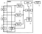
- FIG. 2 is a block diagram of the battery measurement unit and battery control ECU
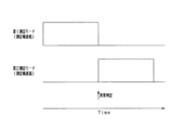
- FIG. 3 is a time chart showing an example of measurement mode switching
- FIG. 4 is a diagram showing each measurement mode
- FIG. 5 is a graph showing a complex impedance plane plot and zero crossing points
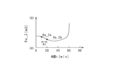
- FIG. 6 is a graph showing the relationship between time and the real part of the zero crossing point during thermal runaway
- FIG. 7 is a graph showing the relationship between time and the rate of change of the real part of the zero crossing point during thermal runaway.
- FIG. 1 is an electrical circuit diagram of a power supply system
- FIG. 2 is a block diagram of the battery measurement unit and battery control ECU
- FIG. 3 is a time chart showing an example of measurement mode switching
- FIG. 4 is a diagram showing each measurement mode
- FIG. 5 is a graph showing a complex impedance plane plot and zero crossing points
- FIG. 6 is a graph showing the relationship between time and the real part of the
- FIG. 8 is a flowchart showing a control procedure for notifying a sign of thermal runaway in a battery cell
- FIG. 9 is a graph showing the relationship between the time during thermal runaway of a battery cell with a capacity of 25 [Ah], the rate of change of the real part of the zero cross point, and the temperature.
- FIG. 10 is a graph showing the relationship between time during thermal runaway of a battery cell with a capacity of 50 [Ah], the rate of change of the real part of the zero cross point, and temperature
- FIG. 11 is a graph showing the relationship between time during thermal runaway of a battery cell with a capacity of 150 [Ah], the rate of change of the real part of the zero cross point, and temperature
- FIG. 12 is a block diagram of a modified example of the battery measuring section
- FIG. 13 is a block diagram of another modification example of the battery measuring section
- FIG. 14 is a block diagram of another modification of the battery measuring section.
- the power supply system 10 includes a motor 20 as a rotating electric machine, an inverter 30 as a power converter that flows three-phase current to the motor 20, a chargeable and dischargeable assembled battery 40, and an assembled battery. 40, a battery control ECU 70 that controls the assembled battery 40, and an upper ECU 60 that controls the motor 20 and the like.
- the motor 20 (motor generator) is a main engine mounted on the vehicle, and is capable of transmitting power to drive wheels (not shown).
- a three-phase permanent magnet synchronous motor is used as the motor 20.
- the inverter 30 is composed of a full bridge circuit having upper and lower arms of the same number as the number of phases of the phase windings, and the current flowing through each phase winding is controlled by turning on/off a switch (semiconductor switching element) provided in each arm. be adjusted.
- a switch semiconductor switching element
- the switch for example, an IGBT (Insulated Gate Bipolar Transistor) can be used.
- the inverter 30 is provided with an inverter control device (not shown), and the inverter control device controls energization by turning on and off each switch in the inverter 30 based on various detection information in the motor 20 and requests for power running drive and power generation. Implement. Thereby, the inverter control device supplies electric power to the motor 20 from the assembled battery 40 via the inverter 30, and drives the motor 20 for power running. Further, the inverter control device causes the motor 20 to generate electricity based on the power from the drive wheels, converts the generated power and supplies it to the assembled battery 40 via the inverter 30, and charges the assembled battery 40.
- the assembled battery 40 is electrically connected to the motor 20 via the inverter 30.
- the assembled battery 40 has an inter-terminal voltage of, for example, 100 [V] or more, and is configured by a plurality of battery modules 41 connected in series.
- the battery module 41 includes a plurality of battery cells 42 connected in series.
- As the battery cell 42 (secondary battery), for example, a lithium iron phosphate battery (LFP battery), a lithium ion storage battery, or a nickel metal hydride storage battery can be used.
- Each battery cell 42 is a storage battery having an electrolytic solution (a solution consisting of an electrolyte and a solvent) and a plurality of electrodes.
- the positive terminal of an electrical load such as the inverter 30 is connected to the positive power path L1 connected to the positive power terminal of the assembled battery 40.
- the negative terminal of an electric load such as the inverter 30 is connected to the negative power path L2 connected to the negative power terminal of the assembled battery 40.
- the positive side power supply path L1 and the negative side power supply path L2 are each provided with a relay switch SMR (system main relay switch), and the relay switch SMR is configured to be able to switch between energization and energization cutoff.
- the battery measuring unit 50 (measuring unit) is a device that measures the state of charge (SOC: State Of Charge), deterioration state (SOH: State Of Health), etc. of each battery cell 42.
- the battery measuring section 50 is connected to the battery control ECU 70, and measures and outputs the complex impedance (impedance) of each battery cell 42 and the like.
- the battery measurement unit 50 can measure the complex impedance (AC impedance) of each battery cell 42 using a plurality of measurement modes with different measurement conditions. The configuration of the battery measuring section 50 will be described later.
- the battery control ECU 70 controls the battery measuring unit 50 to measure the complex impedance of each battery cell 42 in the selected (switched) measurement mode.
- the battery control ECU 70 includes a mode switching section 71 and a TR (thermal runaway) detection section 72.
- the mode switching unit 71 and the TR detection unit 72 will be described later. Note that the battery measurement unit 50 and the battery control ECU 70 constitute a secondary battery thermal runaway sign detection device.
- the host ECU 60 requests the inverter control device to perform power running and power generation based on various information.
- the various information includes, for example, accelerator and brake operation information, vehicle speed, and the state of the assembled battery 40. Further, the host ECU 60 receives input of the results of measuring the state of each battery cell 42 from the battery control ECU 70 .
- the battery measuring section 50 is provided to be able to measure the battery condition of each battery cell 42.
- the battery measuring section 50 includes an alternating current generating section 51 connected to each battery cell 42 via a first electrical path 81 and a voltage response measuring section 52 connected to each battery cell 42 via a second electrical path 82. , a modulation signal generator 53 connected to the alternating current generation section 51, an arithmetic processing section 54 connected to the voltage response measurement section 52 and the modulation signal generator 53, and a communication section 55 connected to the arithmetic processing section 54. It is equipped with.
- the alternating current generating section 51 (current generating section) outputs an alternating current (variable current) using the battery cell 42 as a measurement target as a power source. Specifically, the alternating current generating section 51 causes the battery cell 42 to output an alternating current based on the instruction signal input from the modulation signal generator 53. When the alternating current flows from the battery cell 42, a response signal (voltage fluctuation) reflecting complex impedance information is generated in the voltage between the terminals of the battery cell 42.
- the voltage response measurement unit 52 (voltage measurement unit) measures a response signal (voltage fluctuation) that reflects information on the complex impedance of the battery cell 42 between the terminals of the battery cell 42 .
- the modulation signal generator 53 includes an oscillator that generates an arbitrary waveform AC signal. Then, the modulation signal generator 53 causes the oscillator to generate an AC signal according to a command from the arithmetic processing section 54.
- the AC signal in this embodiment is a sine wave signal, it may be arbitrarily changed as long as it is an AC signal, and may be a rectangular wave, a triangular wave, or the like. Further, a DC bias is applied to the AC signal, so that the AC current (fluctuation current) flowing from the battery cell 42 does not become a negative current (reverse current with respect to the battery cell 42).
- the modulation signal generator 53 converts the AC signal into a digital signal to generate an instruction signal, and instructs (outputs) the AC current generation section 51 to generate an AC current based on the instruction signal.
- the arithmetic processing unit 54 includes a microcomputer consisting of a CPU (arithmetic unit) and a storage device (various types of memory), and realizes various functions by executing programs stored in the storage device.
- Various functions may be realized by electronic circuits that are hardware, or may be realized by both hardware and software.
- the calculation processing unit 54 (calculation unit) has a function of calculating the complex impedance of the battery cell 42.
- the arithmetic processing unit 54 instructs the modulation signal generator 53 to measure the complex impedance measurement frequency.
- the modulation signal generator 53 generates an alternating current (fluctuating current) from the battery cell 42 via the alternating current generating section 51 based on instructions from the arithmetic processing section 54 .
- the voltage response measurement unit 52 measures the voltage between the terminals of the battery cell 42, measures a response signal (voltage fluctuation) in response to an input signal (alternating current), and outputs the measured response signal to the arithmetic processing unit 54. .
- the arithmetic processing unit 54 calculates information regarding the complex impedance of the battery cell 42 based on the response signal. The arithmetic processing unit 54 repeats these series of processes until complex impedances for a plurality of predetermined measurement frequencies within the measurement range are calculated. Further, the calculation processing unit 54 notifies the battery control ECU 70 of the calculation result. Based on the calculation results, the battery control ECU 70 creates, for example, a complex impedance plane plot (Cole-Cole plot) and grasps the characteristics of the electrodes, electrolyte, and the like. Also, the state of charge (SOC) and state of deterioration (SOH) are ascertained.
- SOC state of charge
- SOH state of deterioration
- the complex impedance at a specific frequency may be measured at regular time intervals, and changes in the SOC, SOH, battery temperature, etc. during the drive may be determined based on the time changes in the complex impedance at the specific frequency.
- the complex impedance at a specific frequency may be measured at time intervals such as every day, every week, or every year, and changes in SOH etc. may be grasped based on the time change in the complex impedance at the specific frequency.
- the complex impedance plane plot is not limited to the Cole-Cole plot, and a Bode plot or the like may also be employed.
- each AC signal has a certain wave number. It is necessary to output the voltage and measure the voltage fluctuation during that period. In other words, if the required accuracy is determined in advance, it is necessary to output an AC signal with a wave number corresponding to the accuracy.
- the measurement frequency is different, the number of waves per unit time is also different. Therefore, if the measurement frequency is a low frequency, it is necessary to output an alternating current for a long time compared to a case where the measurement frequency is a high frequency. In other words, the required output period differs depending on the measurement frequency.
- the battery control ECU 70 measures the complex impedance in the first measurement mode, which normally has low measurement accuracy, and determines that the battery cell 42 is abnormal based on the measurement result
- the complex impedance is measured by switching to the second measurement mode, which has higher measurement accuracy than the first measurement mode. That is, normally, the complex impedance (correlation parameter) is measured in the first measurement mode (second mode) with low measurement accuracy, and when it is determined that the battery cell 42 is abnormal, the second measurement mode (second mode) with high measurement accuracy is measured.
- the complex impedance is measured in detail in the first mode). Note that the timing of measuring the complex impedance in the first measurement mode is arbitrary; for example, the complex impedance is measured in the first measurement mode periodically.
- the complex impedance may be measured in the second measurement mode immediately after determining that the battery cell 42 is abnormal in the first measurement mode, or the complex impedance may be measured in the second measurement mode after a predetermined time after determining that the battery cell 42 is abnormal. may be measured.
- the arithmetic processing unit 54 determines the output period of the AC signal based on the set measurement frequency.
- the output period is a period until the wave number of the AC signal is output a predetermined number of times, and is calculated based on the measured frequency.
- the predetermined number of times indicating the number of wave numbers is determined in advance according to the required measurement accuracy. For example, as shown in FIG. 4, the predetermined number of times is 3 (second number) in the first measurement mode, and 9 (first number of times) in the second measurement mode.
- the predetermined number of times in the second measurement mode is greater than the predetermined number of times in the first measurement mode.
- the first measurement mode and the second measurement mode differ in the number of times the alternating current generation section 51 outputs an alternating current and the voltage response measurement section 52 measures the voltage fluctuation of the battery cell 42. That is, the methods of measuring complex impedance are different between the first measurement mode and the second measurement mode. Therefore, the measurement time in the second measurement mode is longer than the measurement time in the first measurement mode. The measurement accuracy in the second measurement mode is higher than the measurement accuracy in the first measurement mode. The power consumption of the battery cell 42 in the first measurement mode is lower than the power consumption of the battery cell 42 in the second measurement mode.
- the arithmetic processing unit 54 instructs the modulation signal generator 53 of the set measurement frequency.
- the modulation signal generator 53 the frequency of the alternating current signal to be outputted from the oscillator is set according to the specified measurement frequency.
- the oscillator of the modulation signal generator 53 generates an alternating current signal according to the set measurement frequency.
- the modulation signal generator 53 converts the generated analog signal of the AC signal into a digital signal, and outputs an instruction signal for outputting the AC signal to the AC current generation unit 51.
- the alternating current generation unit 51 inputs an alternating current (input signal) to the battery cell 42 based on the instruction signal, and causes the battery cell 42 to output an alternating current (variable current).
- the voltage response measurement unit 52 measures the voltage between the terminals of the battery cell 42, measures a response signal (voltage fluctuation) in response to an input signal (alternating current), and converts the analog value of the measured response signal into a digital value. and outputs it to the arithmetic processing section 54.
- the alternating current generation unit 51 may input an alternating current (variable current) to the battery cell 42, or may vary the load on the battery cell 42.
- the arithmetic processing unit 54 calculates information regarding the complex impedance of the battery cell 42 based on the alternating current and voltage fluctuations. Specifically, the arithmetic processing unit 54 acquires a measured value of alternating current. That is, the AC current flowing through the first electrical path 81 is measured, the measured AC current is analyzed based on the frequency of each AC signal (measurement frequency), and each AC signal (measurement signal) that actually flows is extracted. get.
- the arithmetic processing unit 54 analyzes the response signal based on the acquired AC signal, and calculates a value proportional to the real part and a value proportional to the imaginary part (information regarding complex impedance) of the response signal.
- the value proportional to the real part and the value proportional to the imaginary part of the response signal are average values (integral values) from the start of output of each AC signal.
- the arithmetic processing unit 54 determines whether the output period of the AC signal according to each measurement mode has ended. In the first measurement mode, the output period is a period until three AC signals are output, and in the second measurement mode, the output period is a period until nine AC signals are output. If this determination result is negative, the arithmetic processing unit 54 continues measurement and calculation. On the other hand, if the determination result is affirmative, the arithmetic processing unit 54 stops generating the AC signal.
- the arithmetic processing unit 54 acquires values proportional to the real part and imaginary part of the response signal corresponding to the AC signal, and based on them, calculates all or any of the absolute value and phase of the complex impedance at the measurement frequency of the AC signal. Calculate. Then, the arithmetic processing unit 54 notifies the battery control ECU 70 of the calculated complex impedance.
- FIG. 5 is a graph showing a complex impedance plane plot and zero crossing points.
- the battery measuring unit 50 periodically measures the complex impedance of the battery cell 42 while changing the measurement frequency while driving the vehicle equipped with the power supply system 10 (while the assembled battery 40 is in operation), and plots the complex impedance on a plane. Create.
- the horizontal axis is the real part of the complex impedance
- the vertical axis is the imaginary part of the complex impedance.
- the zero crossing point is the point where the graph of complex impedance intersects the horizontal axis, that is, the point where the imaginary part of the complex impedance becomes zero.
- the diameter of the real part of the arc portion mainly represents the reaction resistance, which is the resistance when molecules exit from the electrode into the solution (electrolyte) in the battery cell 42.
- the real part at the zero cross point A indicated by a white circle mainly represents the solution resistance, which is the resistance when the charge moves in the solution in the battery cell 42.
- the present disclosure has focused on the fact that when the battery cell 42 (battery module 41, assembled battery 40) undergoes thermal runaway, gasification of the solution occurs and the real part of the zero cross point A rapidly increases.
- FIG. 6 is a graph showing the relationship between the time t and the real part Re_Z of the zero crossing point during thermal runaway of the battery cell 42.
- the real part Re_Z [m ⁇ ] of the zero-crossing point becomes, for example, Re_Za [m ⁇ ] or Re_Zb [m ⁇ ], and hardly changes.
- the real number part Re_Z of the zero crossing point rapidly increases.
- the real parts Re_Za and Re_Zb of the zero-crossing points are the real parts Re_Z of the zero-crossing points calculated from the current temperature of the battery cell 42 and the current SOC when the temperature T of the battery cell 42 is a predetermined temperature and the temperature of the battery cell 42 is This is a conversion value converted into the real part of the zero cross point when the SOC is a predetermined SOC (predetermined power storage state).
- the reason why the real part Re_Z of the zero-crossing point is converted into a converted value is that the complex impedance of the battery cell 42 is affected by the temperature T and SOC (storage state) of the battery cell 42, and the real part Re_Z of the zero-crossing point also depends on the battery cell 42. This is because it is affected by the temperature T and SOC of .
- FIG. 7 is a graph showing the relationship between the time t and the rate of change ⁇ VRe_Z of the real part Re_Z of the zero-crossing point during thermal runaway of the battery cell 42.
- the rate of change of the real part Re_Z of the zero-crossing point ⁇ VRe_Z [m ⁇ /min] (Re_Zb -Re_Za)/ ⁇ t.
- the rate of change ⁇ VRe_Z of the real part Re_Z of the zero-crossing point rapidly increases. That is, as a sign of thermal runaway in the battery cells 42 (battery module 41, assembled battery 40), the rate of change ⁇ VRe_Z of the real part Re_Z of the zero-crossing point rapidly increases.
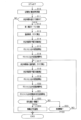
- FIG. 8 is a flowchart showing a control procedure for notifying a sign of thermal runaway of the battery cell 42. This series of processing is executed by the battery measuring section 50 and the battery control ECU 70.
- the battery control ECU 70 periodically grasps the characteristics of the battery cell 42 based on the information regarding the complex impedance of the battery cell 42 measured by the battery measurement unit 50 (S10). For example, the battery control ECU 70 periodically causes the battery measurement unit 50 to measure the complex impedance in the first measurement mode, and when it is determined that the battery cell 42 is abnormal based on the measurement result, the battery control ECU 70 changes the complex impedance to the second measurement mode. Then, the battery measuring section 50 measures the complex impedance.
- the battery control ECU 70 creates a complex impedance plane plot based on the measured complex impedance, and grasps the characteristics of the electrodes, electrolyte, etc., as well as the state of charge (SOC) and state of deterioration (SOH).
- SOC state of charge
- SOH state of deterioration
- the battery control ECU 70 determines whether the vehicle equipped with the power supply system 10 has been stopped for more than the determination time ts (S11). Specifically, it is determined whether the vehicle equipped with the power supply system 10 has been stopped for more than 3 [hours] (judgment time), that is, the assembled battery 40 is stopped (not started, disconnected from the electrical load). ). That the assembled battery 40 is stopped can be determined by, for example, that the power supply system 10 (vehicle) is in sleep mode, that the relay switch SMR is turned off (cut off), or the like. Note that even if the power supply system 10 is in the sleep mode, the battery control ECU 70 can perform the determination (minimum process) of whether the vehicle has been stopped for more than the determination time ts. In this determination, if it is determined that the vehicle equipped with the power supply system 10 has not stopped for more than the determination time ts (S11: NO), this series of processing is ended (END).
- the battery control ECU 70 sets the measurement mode of the battery measurement unit 50 to the first Switch to measurement mode (second mode) (S12).
- the battery measurement unit 50 acquires the temperature T of the battery cell 42 and calculates the SOC of the battery cell 42 (S13).
- the temperature T of the battery cell 42 can be obtained, for example, based on the output of a thermistor or the like attached to the battery cell 42 (battery module 41, assembled battery 40).
- the SOC of the battery cell 42 can be calculated, for example, based on the SOC at a predetermined time and the integrated value of the current flowing through the battery cell 42 thereafter.
- the battery measurement unit 50 outputs an alternating current (fluctuation current) of a predetermined frequency from the battery cell 42, and measures the voltage fluctuation of the battery cell 42 in response to the alternating current (S14).
- the predetermined frequency is a measurement frequency at which the imaginary part of the complex impedance of the battery cell 42 calculated based on the voltage fluctuation of the battery cell 42 is 0, that is, a measurement frequency at which the graph of the complex impedance intersects the horizontal axis.
- the predetermined frequency is the measurement frequency at the zero crossing point A in the Cole-Cole plot of FIG. 5, and can be calculated in advance based on a test using the battery cell 42 or the like. Note that this voltage fluctuation measurement is performed with the battery measurement unit 50 switched to the first measurement mode in the process of S12.
- the battery measurement unit 50 calculates the real part of the zero-crossing point based on the alternating current and voltage fluctuations (S15).
- the method for calculating the real part of the zero-crossing point is the same as the method for calculating the information regarding the complex impedance of the battery cell 42 based on alternating current and voltage fluctuations, as described above.
- the battery control ECU 70 standardizes the real part of the calculated zero-crossing point (S16). Specifically, the battery control ECU 70 calculates the real part of the zero cross point calculated by the battery measurement unit 50 when the temperature T of the battery cell 42 is a predetermined temperature and the SOC of the battery cell 42 is a predetermined SOC (predetermined power storage state). Calculate the conversion value converted into the real part of the zero crossing point when . This conversion value is, for example, added to a map or formula that defines the relationship between the temperature T of the battery cell 42, the SOC of the battery cell 42, and the real part of the zero cross point, and the temperature T of the battery cell 42 and the battery cell obtained in the process of S13.
- It can be calculated by applying the SOC of 42.
- 25 [° C.] can be used as the predetermined temperature
- 90 [%] can be used as the predetermined SOC. Note that this map and formula can be calculated in advance based on a test using the battery cell 42 or the like.
- the battery measurement unit 50 acquires the temperature T of the battery cell 42, The SOC of the battery cell 42 is calculated (S17). This process is executed after waiting until a predetermined time ⁇ t has elapsed since the previous time when an alternating current of a predetermined frequency was output from the battery cell 42 and the voltage fluctuation of the battery cell 42 was measured.
- the battery measurement unit 50 measures the temperature of the battery cell 42. T is acquired, the SOC of the battery cell 42 is calculated, and the processing from S18 onwards is executed.
- the predetermined time ⁇ t is, for example, 1 to 5 [min].
- the process of acquiring the temperature T of the battery cell 42 and the process of calculating the SOC of the battery cell 42 are the same as the process of S13. Note that the predetermined time ⁇ t may be the time since the temperature T of the battery cell 42 was acquired last time and the SOC of the battery cell 42 was calculated.
- the processing from S18 to S20 is the same as the processing from S14 to S16.
- the battery control ECU 70 determines whether the rate of change ⁇ VRe_Z of the real part of the zero-crossing point is larger than the threshold C (S22). In this determination, if it is determined that the rate of change ⁇ VRe_Z of the real part of the zero-crossing point is not greater than the threshold C (S22: NO), the battery control ECU 70 determines whether the vehicle equipped with the power supply system 10 has been stopped. A determination is made (S23). The fact that the vehicle equipped with the power supply system 10 has been stopped can be determined by, for example, that the sleep mode of the power supply system 10 (vehicle) has been canceled or that the relay switch SMR has been turned on (communicated). can.
- the battery control ECU 70 determines that there is a sign of thermal runaway in the battery cell 42, and the host ECU 60 (S24). That is, the battery control ECU 70 detects that there is a sign of thermal runaway in the battery cell 42, and notifies the host ECU 60 through communication that there is a sign of thermal runaway (abnormality) in the battery cell 42.
- the host ECU 60 Upon receiving the notification, the host ECU 60 notifies the driver of the vehicle of the abnormality by, for example, an alarm.
- the host ECU 60 may notify a monitoring center or the like that can communicate with the vehicle of the abnormality. Thereafter, this series of processing ends (END).
- processing in S11 and S12 corresponds to the processing by the mode switching unit 71 (switching unit)
- processing in S14 and S18 corresponds to the processing in the measuring unit
- processing in S13 to S20 corresponds to the processing by the calculation processing unit 54 (calculation unit).
- the processing in S21, S22, and S24 corresponds to the processing (detection step) as the TR detection unit 72 (detection unit).
- the processes of S11, S12, S14, and S18 correspond to the measurement step.
- FIG. 9 to 11 are graphs showing the relationship between the time t, the rate of change of the real part of the zero-crossing point ⁇ VRe_Z (left axis), and the temperature T (right axis) during thermal runaway of battery cells with different capacities.
- the SOC of each battery cell is adjusted to 90%, and the temperature of each battery cell is simulatively increased at a constant rate.
- FIG. 9 shows a battery cell having a capacity of 25 [Ah], a positive electrode made of a nickel-based material NCM (Ni, Co, Al, Mn), and a negative electrode made of Gr (graphite).
- FIG. 9 shows a battery cell having a capacity of 25 [Ah], a positive electrode made of a nickel-based material NCM (Ni, Co, Al, Mn), and a negative electrode made of Gr (graphite).
- FIG. 10 shows a battery cell having a capacity of 50 [Ah], a positive electrode made of a nickel-based material NCM, and a negative electrode made of Gr.
- FIG. 11 shows a battery cell having a capacity of 150 [Ah], a positive electrode of LFP (Li, Fe, P), and a negative electrode of Gr.
- the predetermined frequency at which the imaginary part of the complex impedance of the battery cell 42 becomes 0, that is, the measurement frequency at which the complex impedance graph intersects the horizontal axis differs.
- the predetermined frequency is 400 [Hz]
- the predetermined frequency is 250 [Hz]
- the predetermined frequency is 120 [Hz].
- the rate of change ⁇ VRe_Z of the real part of the zero-crossing point sharply increases earlier than the time when the temperature T rapidly increases due to thermal runaway of the battery cell.
- the battery cell shown in Figure 9 is equipped with a vent valve that discharges internal gas when the internal pressure becomes abnormally high, and when gas is discharged from the vent valve, the real part of the zero cross point changes. Although the speed ⁇ VRe_Z has decreased once, the rate of change ⁇ VRe_Z rapidly increases before the battery cell goes into thermal runaway.
- the modulation signal generator 53, the alternating current generating section 51, and the voltage response measuring section 52 (battery measuring section 50) output an alternating current (fluctuation current) from the battery cell 42 to measure the response of the battery cell 42 to the alternating current.
- a second measurement mode (first mode) in which the number of times the voltage fluctuation is measured is 9 (first number)
- the mode switching unit 71 controls the modulation signal generator 53, the alternating current generation unit 51, and the voltage response measurement unit 52 for the first measurement when the battery cell 42 is stopped (not activated, disconnected from the electrical load). Switch to mode. Therefore, even if the voltage of the battery cell 42 is measured while the battery cell 42 is stopped, the power consumption of the battery cell 42 can be suppressed.
- the TR detection unit 72 calculates the rate of change ⁇ VRe_Z of the real part Re_Z of the complex impedance based on the real part Re_Z of the complex impedance calculated by the arithmetic processing unit 54 and the predetermined time ⁇ t, and the calculated rate of change ⁇ VRe_Z is the threshold value C If it is larger than , it is detected that there is a sign of thermal runaway in the battery cell 42. Therefore, the fact that the real part Re_Z of the zero-crossing point begins to rapidly increase due to gasification of the solution can be detected as a sign of thermal runaway in the battery cell 42.
- the TR detection unit 72 calculates the real part Re_Z of the complex impedance calculated by the arithmetic processing unit 54 when the temperature T of the battery cell 42 is a predetermined temperature and the SOC (storage state) of the battery cell 42 is a predetermined SOC (predetermined storage state).
- the rate of change ⁇ VRe_Z of the real part Re_Z of the complex impedance is calculated based on the conversion values Re_Za, Re_Zb converted into the real part of the complex impedance in the case of the state) and the predetermined time ⁇ t. According to such a configuration, it is possible to accurately detect a sign of thermal runaway of the battery cell 42 in consideration of the influence that the real part Re_Z of the zero-crossing point receives from the temperature T and SOC of the battery cell 42.
- the host ECU 60 may cause the vehicle to perform an evacuation drive. Further, the host ECU 60 may unlock the doors of the vehicle when receiving a notification that there is a sign of thermal runaway in the battery cell 42. This can prevent a situation in which the driver is unable to open the vehicle door in a hurry. Further, the battery control ECU 70 may shut down the assembled battery 40 (power supply system 10) when detecting that there is a sign of thermal runaway in the battery cell 42.
- the power supply system 10 can also be mounted on an electric aircraft or an electric ship, and in that case, it is important to shut down the assembled battery 40 because it is difficult for the driver to escape from the electric aircraft or ship in the event of an abnormality.
- the temperature T of the battery cell 42 is set to a determination temperature (for example, 60[ °C])
- the battery control ECU 70 may notify the host ECU 60 that there is a sign of thermal runaway in the battery cell 42 (S24). According to such a configuration, when there is a low possibility that the battery cell 42 will undergo thermal runaway, it is possible to suppress false detection that there is a sign of thermal runaway in the battery cell 42.
- the TR detection unit 72 does not convert the real part Re_Z of the complex impedance calculated by the arithmetic processing unit 54 into the real part of the complex impedance at the predetermined temperature and the predetermined SOC, but converts it into the real part Re_Z of the complex impedance and the predetermined time ⁇ t. Based on this, the rate of change ⁇ VRe_Z of the real part Re_Z of the complex impedance may be calculated. Then, the TR detection unit 72 may detect that there is a sign of thermal runaway in the battery cell 42 when the calculated rate of change ⁇ VRe_Z is larger than the threshold value C.
- the arithmetic processing unit 54 operates the modulation signal generator so that the alternating current output from the battery cell 42 in the first measurement mode is smaller than the alternating current output from the battery cell 42 in the second measurement mode.
- the oscillator 53 generates an alternating current signal.
- the modulation signal generator 53 converts the alternating current signal into a digital signal to generate an instruction signal, and instructs (outputs) the alternating current generating section 51 to generate an alternating current based on the instruction signal. According to such a configuration, when outputting an alternating current from the battery cell 42 and measuring the voltage fluctuation of the battery cell 42 in response to the alternating current, the power consumption of the battery cell 42 is lower in the first measurement mode than in the second measurement mode. can be further suppressed.
- the calculation processing unit 54 can also shorten the predetermined time ⁇ t as the temperature T of the battery cell 42 is higher. That is, after outputting an alternating current of a predetermined frequency from the battery cell 42 last time and measuring the voltage fluctuation of the battery cell 42, the temperature T of the battery cell 42 is obtained, the SOC of the battery cell 42 is calculated, and the process from S18 onwards
- the waiting time (predetermined time ⁇ t) until the process is executed can be made shorter as the temperature T of the battery cell 42 is higher. According to this configuration, the higher the temperature T of the battery cell 42 is, the more the complex impedance is measured by the battery measurement unit 50 at shorter time intervals. Therefore, when there is a high possibility that the battery cell 42 will undergo thermal runaway, a sign of thermal runaway can be detected earlier.
- the battery measurement unit 50 determines the number of times the AC current generation unit 51 outputs an AC current and the voltage response measurement unit 52 measures the voltage fluctuation of the battery cell 42 in a first measurement mode (second mode). and a third measurement mode (third mode) that is different from the number of times in the second measurement mode (first mode).
- the battery measuring section 50 may include an alternating current generating section 51 and a voltage response measuring section 52 for each battery cell 42. Then, with the plurality of battery cells 42 as measurement targets (targets for detecting signs of thermal runaway), alternating current is applied to each of the battery cells 42 individually or simultaneously to the plurality of battery cells 42, and each voltage response measurement unit 52 You may measure the voltage fluctuation of each battery cell 42 by.
- the battery measuring section 50 may include one alternating current generating section 51 for a plurality of battery cells 42, and may include a voltage response measuring section 52 for each battery cell 42. Then, with the plurality of battery cells 42 as measurement targets (targets for detecting signs of thermal runaway), an alternating current is applied to the plurality of battery cells 42 at once, and voltage fluctuations in each battery cell 42 are measured by each voltage response measuring section 52. You can.
- the battery measuring section 50 may include one alternating current generating section 51 and one voltage response measuring section 52 for a plurality of battery cells 42. Then, with the plurality of battery cells 42 as measurement targets (targets for detecting signs of thermal runaway), alternating current is applied to the plurality of battery cells 42 at once, and voltage fluctuations of the plurality of battery cells 42 are collectively measured by the voltage response measurement unit 52. May be measured.
- alternating current may be passed through the entire battery module 41 and the voltage fluctuation of each battery cell 42 may be measured (detecting signs of thermal runaway), or voltage fluctuations of the entire battery module 41 may be measured (detecting signs of thermal runaway). You can. Alternatively, alternating current may be applied to the entire assembled battery 40 and the voltage fluctuations of each battery cell 42 may be measured (detecting signs of thermal runaway), or voltage fluctuations of the entire assembled battery 40 may be measured (detecting signs of thermal runaway). You may.
- the battery measurement unit 50 may activate the battery control ECU 70.
- the mode switching section 71 and the TR detection section 72 can also be provided inside the battery measuring section 50 (for example, in the arithmetic processing section 54). In that case, the battery measurement unit 50 constitutes a secondary battery thermal runaway sign detection device.
- the power source for the battery control ECU 70 and the battery measuring section 50 may be the high voltage assembled battery 40 (battery module 41), or a low voltage lead acid battery or the like.
- the alternating current generating section 51 can be provided in a charger or the like outside the vehicle.
- the function of detecting signs of thermal runaway in the battery measurement unit 50 and the battery control ECU 70 has been added to the batteries of in-vehicle chargers (AC chargers, DC chargers, V2H (Vehicle To Home) chargers) and replaceable battery packs. It can also be installed in the measurement unit, battery control ECU, charging EMS (Energy Management System) of the charging station, etc.
- the host ECU 60 is in sleep mode when the vehicle is stopped for longer than the judgment time ts (such as when the ignition is turned off), an abnormality sign is finally detected in conjunction with a diagnosis result other than the thermal runaway sign.
- the host ECU 60 or the like may be activated to issue an alarm or the like.
- the power supply of the device to which the signal notifying the abnormality sign is sent may be secured. Note that when an abnormality sign is detected, the process of detecting a thermal runaway sign may be performed a plurality of times, and it may be determined that an abnormality sign has been detected on the condition that the thermal runaway sign is detected a plurality of times. This makes it possible to suppress erroneous detection of abnormal signs and erroneous activation of alarms.
- a secondary battery thermal runaway sign detection device that detects a sign of thermal runaway in a secondary battery (40, 41, 42), A first mode in which the number of times the secondary battery outputs a fluctuating current and measures the voltage fluctuation of the secondary battery in response to the fluctuating current is a first number of times; and a first mode in which the number of times is less than the first number of times.
- a measuring unit (51, 52, 53) capable of measuring the voltage fluctuation in a second mode twice; a switching unit (71) that switches the measuring unit to the second mode when the secondary battery is stopped; With the measurement unit switched to the second mode by the switching unit, the measurement is performed using the fluctuating current at a predetermined frequency such that the imaginary part of the AC impedance of the secondary battery calculated based on the voltage fluctuation is 0.
- a thermal runaway sign detection device for a secondary battery comprising: [Configuration 2] The detection unit converts the real part of the AC impedance into the real part of the AC impedance when the temperature of the secondary battery is a predetermined temperature and the storage state of the secondary battery is a predetermined storage state.
- the thermal runaway sign detection device for a secondary battery according to Configuration 1, which calculates the rate of change of the real part of the AC impedance based on the value.
Landscapes
- Physics & Mathematics (AREA)
- General Physics & Mathematics (AREA)
- Engineering & Computer Science (AREA)
- Manufacturing & Machinery (AREA)
- Chemical & Material Sciences (AREA)
- Chemical Kinetics & Catalysis (AREA)
- Electrochemistry (AREA)
- General Chemical & Material Sciences (AREA)
- Secondary Cells (AREA)
- Tests Of Electric Status Of Batteries (AREA)
Abstract
2次電池(42)の熱暴走予兆検知装置は、2次電池から変動電流を出力させて応答した電圧変動を測定する回数が第1回数である第1モードと、回数が第1回数よりも少ない第2回数である第2モードとにより測定可能である測定部(51、52、53)と、2次電池が停止中である場合に第2モードに切り替える切替部(71)と、を備える。熱暴走予兆検知装置は、電圧変動に基づき算出される2次電池の交流インピーダンスの虚数部が0となる所定周波数の変動電流で測定部により測定された電圧変動に基づき得られる交流インピーダンスの実数部の変化速度が、閾値よりも大きい場合に、2次電池に熱暴走の予兆があると検知する検知部(72)と、を備える。
Description
本出願は、2022年7月12日に出願された日本出願番号2022-111981号に基づくもので、ここにその記載内容を援用する。
本開示は、2次電池が熱暴走する予兆を検知する装置に関する。
従来、測定範囲内の複数の周波数について2次電池の複素インピーダンスを測定し、測定結果に基づいて複素インピーダンス平面プロット(コールコールプロット、Bode plot等)を作成し、2次電池の電極及び電解質などの特性を把握する装置がある(特許文献1参照)。
ところで、ごく希に2次電池が熱暴走して、火災が発生することがある。その対策として、把握した2次電池の電極及び電解質などの特性から、2次電池が熱暴走する予兆を検知することが考えられる。2次電池の熱暴走は、2次電池の動作中(充放電中)に限らず、停止中(非起動中、電気負荷と遮断中)も発生することが知られている。このため、2次電池の停止中も継続して熱暴走の予兆を検知する必要がある。その場合、特許文献1に記載された方法により2次電池の特性を把握して熱暴走の予兆を検知しようとすると、2次電池の電力が多く消費されるおそれがある。
本開示は、上記課題を解決するためになされたものであり、その主たる目的は、2次電池の電力消費を抑制しつつ熱暴走の予兆を検知することにある。
上記課題を解決するための第1の手段は、
2次電池が熱暴走する予兆を検知する、2次電池の熱暴走予兆検知装置であって、
前記2次電池から変動電流を出力させて前記変動電流に応答した前記2次電池の電圧変動を測定する回数が第1回数である第1モードと、前記回数が前記第1回数よりも少ない第2回数である第2モードとにより前記電圧変動を測定可能である測定部と、
前記2次電池が停止中である場合に前記測定部を前記第2モードに切り替える切替部と、
前記切替部により前記測定部が前記第2モードに切り替えられた状態で、前記電圧変動に基づき算出される前記2次電池の交流インピーダンスの虚数部が0となる所定周波数の前記変動電流で前記測定部により測定された前記電圧変動に基づき得られる前記交流インピーダンスの実数部の変化速度が、閾値よりも大きい場合に前記2次電池に熱暴走の予兆があると検知する検知部と、
を備える2次電池の熱暴走予兆検知装置。
2次電池が熱暴走する予兆を検知する、2次電池の熱暴走予兆検知装置であって、
前記2次電池から変動電流を出力させて前記変動電流に応答した前記2次電池の電圧変動を測定する回数が第1回数である第1モードと、前記回数が前記第1回数よりも少ない第2回数である第2モードとにより前記電圧変動を測定可能である測定部と、
前記2次電池が停止中である場合に前記測定部を前記第2モードに切り替える切替部と、
前記切替部により前記測定部が前記第2モードに切り替えられた状態で、前記電圧変動に基づき算出される前記2次電池の交流インピーダンスの虚数部が0となる所定周波数の前記変動電流で前記測定部により測定された前記電圧変動に基づき得られる前記交流インピーダンスの実数部の変化速度が、閾値よりも大きい場合に前記2次電池に熱暴走の予兆があると検知する検知部と、
を備える2次電池の熱暴走予兆検知装置。
上記構成によれば、測定部は、前記2次電池から変動電流を出力させて前記変動電流に応答した前記2次電池の電圧変動を測定する回数が第1回数である第1モードと、前記回数が前記第1回数よりも少ない第2回数である第2モードとにより前記電圧変動を測定可能である。前記2次電池から変動電流を出力させて前記変動電流に応答した前記2次電池の電圧変動を測定する際に、第2モードでは第1モードよりも2次電池の電力消費を抑制することができる。切替部は、前記2次電池が停止中(非起動中、電気負荷と遮断中)である場合に、前記測定部を前記第2モードに切り替える。このため、2次電池の停止中に2次電池の電圧変動を測定したとしても、2次電池の電力消費を抑制することができる。
前記交流インピーダンスの虚数部が0となる所定周波数の前記変動電流で算出した前記交流インピーダンスの実数部(以下、「ゼロクロス点の実数部」という)は、2次電池において溶液(電解液)中を電荷が移動する際の抵抗である溶液抵抗を主に表している。2次電池が熱暴走する際には溶液のガス化が起きてゼロクロス点の実数部が急増することに、本願開示者は着目した。
そこで、検知部は、前記切替部により前記測定部が前記第2モードに切り替えられた状態で、前記電圧変動に基づき算出される前記2次電池の交流インピーダンスの虚数部が0となる所定周波数の前記変動電流で前記測定部により測定された前記電圧変動に基づき得られる前記交流インピーダンスの実数部の変化速度が、閾値よりも大きい場合に前記2次電池に熱暴走の予兆があると検知する。このため、溶液のガス化が起きてゼロクロス点の実数部が急増し始めたことを、2次電池が熱暴走する予兆として検知することができる。しかも、測定範囲内の複数の周波数について2次電池の交流インピーダンスを測定する必要がなく、交流インピーダンスの虚数部が0となる所定周波数について2次電池の交流インピーダンスを測定すればよいため、2次電池の電力消費をさらに抑制することができる。
2次電池の交流インピーダンスは、2次電池の温度及び蓄電状態(SOC:State Of Charge)により影響を受ける。このため、ゼロクロス点の実数部も、2次電池の温度及び蓄電状態により影響を受ける。
この点、第2の手段では、前記検知部は、前記交流インピーダンスの実数部を、前記2次電池の温度が所定温度であり且つ前記2次電池の蓄電状態が所定蓄電状態である場合の前記交流インピーダンスの実数部に換算した換算値に基づいて前記交流インピーダンスの実数部の変化速度を算出する。こうした構成によれば、ゼロクロス点の実数部が2次電池の温度及び蓄電状態から受ける影響を考慮して、2次電池の熱暴走の予兆を正確に検知することができる。
第3の手段では、前記第2モードにおいて前記2次電池から出力させる前記変動電流の大きさは、前記第1モードにおいて前記2次電池から出力させる前記変動電流の大きさよりも小さい。こうした構成によれば、前記2次電池から変動電流を出力させて前記変動電流に応答した前記2次電池の電圧変動を測定する際に、第2モードでは第1モードよりも2次電池の電力消費をさらに抑制することができる。
第4の手段では、前記切替部により前記測定部が前記第2モードに切り替えられた状態で、前記所定周波数の前記変動電流で前記電圧変動を前記測定部により所定時間の間隔で測定させ、測定された前記電圧変動に基づいて前記交流インピーダンスの実数部を算出する算出部を備え、前記検知部は、前記算出部により算出された前記交流インピーダンスの実数部及び前記所定時間に基づいて前記交流インピーダンスの実数部の変化速度を算出し、前記算出部は、前記2次電池の温度が高いほど、前記所定時間を短くする。こうした構成によれば、前記2次電池の温度が高いほど、短い時間間隔で前記交流インピーダンスが前記測定部により測定される。このため、2次電池が熱暴走する可能性が高い場合に、熱暴走の予兆をより早期に検知することができる。
第5の手段は、
2次電池が熱暴走する予兆を検知する、2次電池の熱暴走予兆検知方法であって、
前記2次電池から変動電流を出力させて前記変動電流に応答した前記2次電池の電圧変動を測定する回数が第1回数である第1モードと、前記回数が前記第1回数よりも少ない第2回数である第2モードとのうち、前記2次電池が停止中である場合に前記第2モードに切り替えて、前記電圧変動を測定する測定ステップと、
前記第2モードに切り替えた状態で、前記電圧変動に基づき算出される前記2次電池の交流インピーダンスの虚数部が0となる所定周波数の前記変動電流で測定された前記電圧変動に基づき得られる前記交流インピーダンスの実数部の変化速度が、閾値よりも大きい場合に前記2次電池に熱暴走の予兆があると検知する検知ステップと、
を備える。
2次電池が熱暴走する予兆を検知する、2次電池の熱暴走予兆検知方法であって、
前記2次電池から変動電流を出力させて前記変動電流に応答した前記2次電池の電圧変動を測定する回数が第1回数である第1モードと、前記回数が前記第1回数よりも少ない第2回数である第2モードとのうち、前記2次電池が停止中である場合に前記第2モードに切り替えて、前記電圧変動を測定する測定ステップと、
前記第2モードに切り替えた状態で、前記電圧変動に基づき算出される前記2次電池の交流インピーダンスの虚数部が0となる所定周波数の前記変動電流で測定された前記電圧変動に基づき得られる前記交流インピーダンスの実数部の変化速度が、閾値よりも大きい場合に前記2次電池に熱暴走の予兆があると検知する検知ステップと、
を備える。
上記工程によれば、測定ステップでは、前記2次電池から変動電流を出力させて前記変動電流に応答した前記2次電池の電圧変動を測定する回数が第1回数である第1モードと、前記回数が前記第1回数よりも少ない第2回数である第2モードとのうち、前記2次電池が停止中である場合に前記第2モードに切り替えて、前記電圧変動を測定する。前記2次電池から変動電流を出力させて前記変動電流に応答した前記2次電池の電圧変動を測定する際に、第2モードでは第1モードよりも2次電池の電力消費を抑制することができる。測定ステップでは、前記2次電池が停止中である場合に前記第2モードに切り替える。このため、2次電池の停止中に2次電池の電圧変動を測定したとしても、2次電池の電力消費を抑制することができる。
前記交流インピーダンスの虚数部が0となる所定周波数の前記変動電流で算出した前記交流インピーダンスの実数部(ゼロクロス点の実数部)は、2次電池において溶液中を電荷が移動する際の抵抗である溶液抵抗を主に表している。2次電池が熱暴走する際には溶液のガス化が起きてゼロクロス点の実数部が急増することに、本願開示者は着目した。
そこで、検知ステップでは、前記第2モードに切り替えた状態で、前記電圧変動に基づき算出される前記2次電池の交流インピーダンスの虚数部が0となる所定周波数の前記変動電流で測定された前記電圧変動に基づき得られる前記交流インピーダンスの実数部の変化速度が、閾値よりも大きい場合に前記2次電池に熱暴走の予兆があると検知する。このため、溶液のガス化が起きてゼロクロス点の実数部が急増し始めたことを、2次電池が熱暴走する予兆として検知することができる。しかも、測定範囲内の複数の周波数について2次電池の交流インピーダンスを測定する必要がなく、交流インピーダンスの虚数部が0となる所定周波数について2次電池の交流インピーダンスを測定すればよいため、2次電池の電力消費をさらに抑制することができる。
本開示についての上記目的およびその他の目的、特徴や利点は、添付の図面を参照しながら下記の詳細な記述により、より明確になる。その図面は、
図1は、電源システムの電気回路図であり、
図2は、電池測定部及び電池制御ECUのブロック図であり、
図3は、測定モード切替の一例を示すタイムチャートであり、
図4は、各測定モードを示す図であり、
図5は、複素インピーダンス平面プロットとゼロクロス点を示すグラフであり、
図6は、熱暴走時における時間とゼロクロス点の実数部との関係を示すグラフであり、
図7は、熱暴走時における時間とゼロクロス点の実数部の変化速度との関係を示すグラフであり、
図8は、電池セルの熱暴走予兆を通知する制御の手順を示すフローチャートであり、
図9は、容量25[Ah]の電池セルの熱暴走時における時間と、ゼロクロス点の実数部の変化速度と、温度との関係を示すグラフであり、
図10は、容量50[Ah]の電池セルの熱暴走時における時間と、ゼロクロス点の実数部の変化速度と、温度との関係を示すグラフであり、
図11は、容量150[Ah]の電池セルの熱暴走時における時間と、ゼロクロス点の実数部の変化速度と、温度との関係を示すグラフであり、
図12は、電池測定部の変更例のブロック図であり、
図13は、電池測定部の他の変更例のブロック図であり、
図14は、電池測定部の他の変更例のブロック図である。
以下、「2次電池の熱暴走予兆検知装置」を車両(例えば、ハイブリッド車や電気自動車)の電源システムに適用した一実施形態について、図面を参照しつつ説明する。
図1に示すように、電源システム10は、回転電機としてのモータ20と、モータ20に対して3相電流を流す電力変換器としてのインバータ30と、充放電可能な組電池40と、組電池40の状態を測定する電池測定部50と、組電池40を制御する電池制御ECU70と、モータ20などを制御する上位ECU60と、を備えている。
モータ20(モータジェネレータ)は、車載主機であり、図示しない駆動輪と動力伝達可能とされている。本実施形態では、モータ20として、3相の永久磁石同期モータを用いている。インバータ30は、相巻線の相数と同数の上下アームを有するフルブリッジ回路により構成されており、各アームに設けられたスイッチ(半導体スイッチング素子)のオンオフにより、各相巻線において通電電流が調整される。スイッチとしては、例えばIGBT(Insulated Gate Bipolar Transistor)を採用することができる。
インバータ30には、図示しないインバータ制御装置が設けられており、インバータ制御装置は、モータ20における各種の検出情報や、力行駆動及び発電の要求に基づいて、インバータ30における各スイッチのオンオフにより通電制御を実施する。これにより、インバータ制御装置は、組電池40からインバータ30を介してモータ20に電力を供給し、モータ20を力行駆動させる。また、インバータ制御装置は、駆動輪からの動力に基づいてモータ20を発電させ、インバータ30を介して、発電電力を変換して組電池40に供給し、組電池40を充電させる。
組電池40は、インバータ30を介して、モータ20に電気的に接続されている。組電池40は、例えば百[V]以上となる端子間電圧を有し、複数の電池モジュール41が直列接続されて構成されている。電池モジュール41は、複数の電池セル42が直列接続されて構成されている。電池セル42(2次電池)として、例えば、リン酸鉄リチウムイオン電池(LFP電池)や、リチウムイオン蓄電池、ニッケル水素蓄電池を用いることができる。各電池セル42は、電解液(電解質及び溶媒からなる溶液)と複数の電極とを有する蓄電池である。
図1に示すように、組電池40の正極側電源端子に接続される正極側電源経路L1には、インバータ30等の電気負荷の正極側端子が接続されている。同様に、組電池40の負極側電源端子に接続される負極側電源経路L2には、インバータ30等の電気負荷の負極側端子が接続されている。なお、正極側電源経路L1及び負極側電源経路L2には、それぞれリレースイッチSMR(システムメインリレースイッチ)が設けられており、リレースイッチSMRにより、通電及び通電遮断が切り替え可能に構成されている。
電池測定部50(測定部)は、各電池セル42の蓄電状態(SOC:State Of Charge)及び劣化状態(SOH:State Of Health)などを測定する装置である。電池測定部50は、電池制御ECU70に接続されており、各電池セル42の複素インピーダンス(インピーダンス)などを測定して出力する。電池測定部50は、測定条件が異なる複数の測定モードにより各電池セル42の複素インピーダンス(交流インピーダンス)を測定可能である。電池測定部50の構成については、後述する。
電池制御ECU70(切替部、検知部)は、電池測定部50を制御して、選択した(切り替えた)測定モードにより各電池セル42の複素インピーダンスを測定させる。電池制御ECU70は、モード切替部71及びTR(Thermal Runaway)検知部72を備えている。モード切替部71及びTR検知部72については後述する。なお、電池測定部50及び電池制御ECU70により、2次電池の熱暴走予兆検知装置が構成されている。
上位ECU60は、各種情報に基づいて、インバータ制御装置に対して力行駆動及び発電の要求を行う。各種情報には、例えば、アクセル及びブレーキの操作情報、車速、組電池40の状態などが含まれる。また、上位ECU60は、電池制御ECU70から各電池セル42の状態を測定した結果等を入力する。
次に、電池測定部50及び電池制御ECU70について詳しく説明する。図2に示すように、電池測定部50は、電池セル42毎の電池状態を測定可能に設けられている。電池測定部50は、第1電気経路81を介して各電池セル42に接続された交流電流生成部51と、第2電気経路82を介して各電池セル42に接続された電圧応答測定部52と、交流電流生成部51に接続された変調信号発生器53と、電圧応答測定部52及び変調信号発生器53に接続された演算処理部54と、演算処理部54に接続された通信部55と、を備えている。
交流電流生成部51(電流生成部)は、測定対象である電池セル42を電源として、交流電流(変動電流)を出力させる。具体的に説明すると、交流電流生成部51は、変調信号発生器53から入力される指示信号に基づいて、交流電流を電池セル42から出力させる。交流電流が電池セル42から流れることにより、電池セル42の端子間電圧には、複素インピーダンスの情報を反映した応答信号(電圧変動)が生じる。電圧応答測定部52(電圧測定部)は、電池セル42の端子間において、電池セル42の複素インピーダンスの情報を反映した応答信号(電圧変動)を測定する。
変調信号発生器53は、任意波形の交流信号を発生する発振器を備えている。そして、変調信号発生器53は、演算処理部54からの命令に従って、発振器に交流信号を発生させる。
本実施形態における交流信号は、正弦波信号とされているが、交流信号であれば、任意に変更してよく、矩形波や三角波などであってもよい。また、交流信号には、直流バイアスがかけられており、電池セル42から流れる交流電流(変動電流)が負の電流(電池セル42に対して逆流)とならないようになっている。
そして、変調信号発生器53は、交流信号をデジタル信号に変換して指示信号を生成し、指示信号に基づいて交流電流生成部51に交流電流を発生させるように指示(出力)する。
演算処理部54は、CPU(演算装置)や記憶装置(各種メモリ)からなるマイコンを備えており、記憶装置に記憶されたプログラムを実行することにより、各種機能を実現する。各種機能は、ハードウェアである電子回路によって実現されてもよいし、ハードウェア及びソフトウェアの双方によって実現されてもよい。
演算処理部54(算出部)は、電池セル42の複素インピーダンスを算出する機能を備えている。ここで、複素インピーダンスの算出方法の概要について説明する。演算処理部54は、複素インピーダンスの測定周波数を変調信号発生器53に指示する。変調信号発生器53は、交流電流生成部51を介して、演算処理部54の指示に基づいて、電池セル42から交流電流(変動電流)を発生させる。電圧応答測定部52は、電池セル42の端子間電圧を測定して、入力信号(交流電流)に応答する応答信号(電圧変動)を測定し、測定した応答信号を演算処理部54に出力する。
演算処理部54は、応答信号に基づいて、電池セル42の複素インピーダンスに関する情報を算出する。演算処理部54は、これら一連の処理を、測定範囲内において予め決められた複数の測定周波数についての複素インピーダンスが算出されるまで繰り返す。また、演算処理部54は、算出結果を電池制御ECU70に通知する。電池制御ECU70は、算出結果に基づいて、例えば、複素インピーダンス平面プロット(コールコールプロット)を作成し、電極及び電解質などの特性を把握する。また、蓄電状態(SOC)や劣化状態(SOH)を把握する。
なお、コールコールプロット全体を必ずしも作成する必要はなく、その一部に着目してもよい。例えば、走行時、一定の時間間隔で特定周波数の複素インピーダンスを測定し、特定周波数の複素インピーダンスの時間変化に基づいて、SOC、SOH及び電池温度等の走行時における変化を把握してもよい。または、1日毎、1週ごと、若しくは1年ごとといった時間間隔で特定周波数の複素インピーダンスを測定し、特定周波数の複素インピーダンスの時間変化に基づいて、SOH等の変化を把握してもよい。また、複素インピーダンス平面プロットは、コールコールプロットに限らず、Bode plot等を採用することもできる。
ところで、複素インピーダンスの測定精度を確保するためには、電圧変動の測定値を平均化して(積分値にして)誤差を抑制する必要があり、測定周波数ごとに各交流信号について、それぞれある程度の波数を出力させ、その期間中、電圧変動を測定する必要がある。つまり、要求される精度があらかじめ決まっている場合、精度に応じた波数の交流信号を出力させる必要がある。ここで、測定周波数が異なれば、単位時間あたりの波数も異なる。したがって、測定周波数が、低周波数であれば、高周波数である場合に比較して、長時間の交流電流を出力させる必要があることとなる。つまり、測定周波数ごとに、必要となる出力期間が異なる。
例えば、図3に示すように、電池制御ECU70は、通常時に測定精度が低い第1測定モードで複素インピーダンスを測定させ、その測定結果に基づいて電池セル42が異常であると判定した場合に、第1測定モードよりも測定精度が高い第2測定モードに切り替えて複素インピーダンスを測定させる。すなわち、通常時は測定精度が低い第1測定モード(第2モード)で複素インピーダンス(相関パラメータ)を測定し、電池セル42が異常であると判定した場合は測定精度が高い第2測定モード(第1モード)で詳細に複素インピーダンスを測定する。なお、第1測定モードで複素インピーダンスを測定する時期は任意であり、例えば定期的に第1測定モードで複素インピーダンスを測定する。また、第1測定モードにおいて電池セル42が異常であると判定した直後に第2測定モードで複素インピーダンスを測定させてもよいし、異常であると判定した所定時間後に第2測定モードで複素インピーダンスを測定させてもよい。
具体的には、演算処理部54は、設定した測定周波数に基づいて、交流信号の出力期間を決定する。出力期間は、交流信号の波数を所定回数出力させるまでの期間であり、測定周波数に基づいて算出される。波数の回数を示す所定回数は、要求される測定精度に応じて予め決定されている。例えば、図4に示すように、第1測定モードでは所定回数は3(第2回数)であり、第2測定モードでは所定回数は9(第1回数)である。第2測定モードの所定回数は、第1測定モードの所定回数よりも多い。このように、第1測定モードと第2測定モードとでは、交流電流生成部51により交流電流を出力させて電圧応答測定部52により電池セル42の電圧変動を測定する回数が異なっている。すなわち、第1測定モードと第2測定モードとでは、複素インピーダンスを測定する方法が異なっている。このため、第2測定モードの測定時間は、第1測定モードの測定時間よりも長い。第2測定モードの測定精度は、第1測定モードの測定精度よりも高い。第1測定モードでの電池セル42の電力消費は、第2測定モードでの電池セル42の電力消費よりも少ない。
次に演算処理部54は、設定された測定周波数を変調信号発生器53に指示する。変調信号発生器53では、指示された測定周波数に従って、発振器に出力させる交流信号の周波数が設定される。そして、変調信号発生器53の発振器は、設定された測定周波数に従って、交流信号を生成する。変調信号発生器53は、生成した交流信号のアナログ信号をデジタル信号に変換して、交流信号を出力させる指示信号を交流電流生成部51に出力する。
交流電流生成部51は、指示信号に基づいて電池セル42に交流電流(入力信号)を入力し、電池セル42から交流電流(変動電流)を出力させる。電圧応答測定部52は、電池セル42の端子間電圧を測定して、入力信号(交流電流)に応答する応答信号(電圧変動)を測定し、測定した応答信号のアナログ値をデジタル値に変換して演算処理部54に出力する。なお、交流電流生成部51は、交流電流(変動電流)を電池セル42に入力してもよいし、電池セル42に対する負荷を変動させてもよい。
演算処理部54は、交流電流及び電圧変動に基づいて、電池セル42の複素インピーダンスに関する情報を算出する。具体的に説明すると、演算処理部54は、交流電流の測定値を取得する。つまり、第1電気経路81に流れる交流電流を測定し、測定された交流電流を各交流信号の周波数(測定周波数)によって解析し、実際に流れた各交流信号(測定信号)を抽出して、取得する。
そして、演算処理部54は、取得した交流信号に基づいて応答信号を解析し、応答信号の実数部に比例した値と虚数部に比例した値(複素インピーダンスに関する情報)を算出する。なお、応答信号の実数部に比例した値と虚数部に比例した値は、それぞれ各交流信号の出力開始時からの平均値(積分値)である。
次に、演算処理部54は、各測定モードに応じた交流信号の出力期間が終了したか否かを判定する。第1測定モードでは出力期間は3つの交流信号を出力させるまでの期間であり、第2測定モードでは出力期間は9つの交流信号を出力させるまでの期間である。この判定結果が否定の場合、演算処理部54は、演算処理部54は、測定及び算出を継続する。一方、判定結果が肯定の場合、演算処理部54は交流信号の発生を停止させる。
演算処理部54は、交流信号に対応する応答信号の実数部及び虚数部に比例した値を取得し、それらに基づいて、交流信号の測定周波数における複素インピーダンスの絶対値、位相のすべて若しくはいずれかを算出する。そして、演算処理部54は、算出した複素インピーダンスを電池制御ECU70に通知する。
図5は、複素インピーダンス平面プロットとゼロクロス点を示すグラフである。電池測定部50は、電源システム10を搭載した車両の運転時(組電池40の動作中)に定期的に、測定周波数を変更しつつ電池セル42の複素インピーダンスを測定して、複素インピーダンス平面プロットを作成する。横軸は、複素インピーダンスの実数部であり、縦軸は複素インピーダンスの虚数部である。ゼロクロス点は、複素インピーダンスのグラフが横軸と交差する点、すなわち複素インピーダンスの虚数部が0となる点である。
同図の黒点では、低周波数から高周波数まで広範囲の周波数について複素インピーダンスを測定している。円弧部の実数部における直径は、電池セル42において電極から分子が溶液(電解液)中に出る際の抵抗である反応抵抗を主に表している。白丸で示すゼロクロス点Aにおける実数部は、電池セル42において溶液中を電荷が移動する際の抵抗である溶液抵抗を主に表している。ここで、電池セル42(電池モジュール41、組電池40)が熱暴走する際には溶液のガス化が起きてゼロクロス点Aの実数部が急増することに、本願開示者は着目した。
図6は、電池セル42の熱暴走時における時間tとゼロクロス点の実数部Re_Zとの関係を示すグラフである。電池セル42が熱暴走する前では、ゼロクロス点の実数部Re_Z[mΩ]は、例えばRe_Za[mΩ]や、Re_Zb[mΩ]となり、ほとんど変化しない。そして、電池セル42が熱暴走すると、ゼロクロス点の実数部Re_Zは急増している。なお、ゼロクロス点の実数部Re_Za,Re_Zbは、電池セル42の現在の温度及び現在のSOCで算出したゼロクロス点の実数部Re_Zを、電池セル42の温度Tが所定温度であり且つ電池セル42のSOCが所定SOC(所定蓄電状態)である場合のゼロクロス点の実数部に換算した換算値である。ゼロクロス点の実数部Re_Zを換算値に換算する理由は、電池セル42の複素インピーダンスは、電池セル42の温度T及びSOC(蓄電状態)により影響を受け、ゼロクロス点の実数部Re_Zも電池セル42の温度T及びSOCにより影響を受けるためである。
図7は、電池セル42の熱暴走時における時間tとゼロクロス点の実数部Re_Zの変化速度ΔVRe_Zとの関係を示すグラフである。ゼロクロス点の実数部Re_Zの変化速度ΔVRe_Zは、ゼロクロス点の実数部Re_Zの変化量ΔRe_Zを、その変化に要した時間Δtで割ることにより算出することができる(ΔVRe_Z=ΔRe_Z/Δt)。例えば、ゼロクロス点の実数部Re_Z[mΩ]が時間Δt[min]においてRe_Za[mΩ]からRe_Zb[mΩ]へ変化した場合、ゼロクロス点の実数部Re_Zの変化速度ΔVRe_Z[mΩ/min]=(Re_Zb-Re_Za)/Δtとなる。電池セル42が熱暴走する際に、その前段階においてゼロクロス点の実数部Re_Zの変化速度ΔVRe_Zは急増している。すなわち、電池セル42(電池モジュール41、組電池40)が熱暴走する予兆として、ゼロクロス点の実数部Re_Zの変化速度ΔVRe_Zが急増している。そこで、本実施形態では、ゼロクロス点の実数部Re_Zの変化速度ΔVRe_Zが閾値Cを超えた(閾値Cよりも大きい)場合に、電池セル42に熱暴走の予兆があると検知する。
図8は、電池セル42の熱暴走予兆を通知する制御の手順を示すフローチャートである。この一連の処理は、電池測定部50及び電池制御ECU70により実行される。
電池制御ECU70は、電池測定部50が測定した電池セル42の複素インピーダンスに関する情報に基づいて、定期的に電池セル42の特性を把握する(S10)。例えば、電池制御ECU70は、定期的に電池測定部50により第1測定モードで複素インピーダンスを測定させ、その測定結果に基づいて電池セル42が異常であると判定した場合に、第2測定モードに切り替えて電池測定部50により複素インピーダンスを測定させる。そして、電池制御ECU70は、測定された複素インピーダンスに基づいて複素インピーダンス平面プロットを作成し、電極及び電解質などの特性、並びに蓄電状態(SOC)や劣化状態(SOH)を把握する。
続いて、電池制御ECU70は、電源システム10を搭載した車両が判定時間tsを超えて停車中であるか否か判定する(S11)。具体的には、電源システム10を搭載した車両が例えば3[hour](判定時間)を超えて停車中であるか否か、すなわち組電池40が停止中(非起動中、電気負荷と遮断中)であるか否か判定する。組電池40が停止中であることは、例えば、電源システム10(車両)がスリープモードになっている、リレースイッチSMRがオフ(遮断)になっている等により判定することができる。なお、電池制御ECU70は、電源システム10がスリープモードであっても、車両が判定時間tsを超えて停車中であるか否かの判定(最低限の処理)を実行可能である。この判定において、電源システム10を搭載した車両が判定時間tsを超えて停車中でないと判定した場合(S11:NO)、この一連の処理を終了する(END)。
一方、S11の判定において、電源システム10を搭載した車両が判定時間tsを超えて停車中であると判定した場合(S11:YES)、電池制御ECU70は、電池測定部50の測定モードを第1測定モード(第2モード)に切り替える(S12)。電池測定部50は、電池セル42の温度Tを取得し、電池セル42のSOCを算出する(S13)。電池セル42の温度Tは、例えば電池セル42(電池モジュール41、組電池40)に取り付けられたサーミスタ等の出力に基づいて取得することができる。電池セル42のSOCは、例えば所定時点におけるSOCとその後に電池セル42を流れた電流の積算値とに基づいて算出することができる。
続いて、電池測定部50は、所定周波数の交流電流(変動電流)を電池セル42から出力させて、交流電流に応答した電池セル42の電圧変動を測定する(S14)。所定周波数は、電池セル42の電圧変動に基づき算出される電池セル42の複素インピーダンスの虚数部が0となる測定周波数、すなわち複素インピーダンスのグラフが横軸と交差する測定周波数である。例えば、所定周波数は、図5のコールコールプロットにおいてゼロクロス点Aとなる測定周波数であり、電池セル42を用いた試験等に基づいて予め算出しておくことができる。なお、この電圧変動の測定は、S12の処理で電池測定部50が第1測定モードに切り替えられた状態で実行される。
続いて、電池測定部50は、交流電流及び電圧変動に基づいてゼロクロス点の実数部を算出する(S15)。ゼロクロス点の実数部を算出する方法は、上述したように、交流電流及び電圧変動に基づいて電池セル42の複素インピーダンスに関する情報を算出する方法と同様である。
続いて、電池制御ECU70は、算出されたゼロクロス点の実数部を標準化する(S16)。具体的には、電池制御ECU70は、電池測定部50により算出されたゼロクロス点の実数部を、電池セル42の温度Tが所定温度であり且つ電池セル42のSOCが所定SOC(所定蓄電状態)である場合のゼロクロス点の実数部に換算した換算値を算出する。この換算値は、例えば電池セル42の温度T、電池セル42のSOC、及びゼロクロス点の実数部の関係を規定したマップ又は数式に、S13の処理で取得した電池セル42の温度T及び電池セル42のSOCを適用することにより算出することができる。例えば、所定温度として25[℃]、所定SOCとして90[%]を採用することができる。なお、このマップ及び数式は、電池セル42を用いた試験等に基づいて予め算出しておくことができる。
続いて、前回に所定周波数の交流電流を電池セル42から出力させて電池セル42の電圧変動を測定してから所定時間Δt後に、電池測定部50は、電池セル42の温度Tを取得し、電池セル42のSOCを算出する(S17)。この処理は、前回に所定周波数の交流電流を電池セル42から出力させて電池セル42の電圧変動を測定してから所定時間Δtが経過するまで待機してから実行される。すなわち、前回に所定周波数の交流電流を電池セル42から出力させて電池セル42の電圧変動を測定してから所定時間Δtが経過したことを条件として、電池測定部50は、電池セル42の温度Tを取得し、電池セル42のSOCを算出し、S18以降の処理を実行する。所定時間Δtは、例えば1~5[min]である。電池セル42の温度Tを取得する処理と、電池セル42のSOCを算出する処理は、S13の処理と同一である。なお、所定時間Δtは、前回に電池セル42の温度Tを取得し、電池セル42のSOCを算出してからの時間であってもよい。
S18~S20の処理は、S14~S16の処理と同一である。
続いて、電池制御ECU70は、ゼロクロス点の実数部の変化速度を算出する(S21)。例えば、前回に算出したゼロクロス点の実数部の換算値Re_Zaから、その所定時間Δt後に算出したゼロクロス点の実数部の換算値Re_Zbへの変化量ΔRe_Z(換算値の差)を所定時間Δtで割って、ゼロクロス点の実数部の変化速度ΔVRe_Zを算出する(ΔVRe_Z=ΔRe_Z/Δt)。
続いて、電池制御ECU70は、ゼロクロス点の実数部の変化速度ΔVRe_Zが閾値Cよりも大きいか否か判定する(S22)。この判定において、ゼロクロス点の実数部の変化速度ΔVRe_Zが閾値Cよりも大きくないと判定した場合(S22:NO)、電池制御ECU70は、電源システム10を搭載した車両の停車が解除されたか否か判定する(S23)。電源システム10を搭載した車両の停車が解除されたことは、例えば電源システム10(車両)のスリープモードが解除されている、リレースイッチSMRがオン(連通)になっている等により判定することができる。この判定において、電源システム10を搭載した車両の停車が解除されていないと判定した場合(S23:NO)、S17の処理から再度実行する。一方、S23の判定において、電源システム10を搭載した車両の停車が解除されていると判定した場合(S23:YES)、この一連の処理を終了する(END)。
また、S22の判定において、ゼロクロス点の実数部の変化速度ΔVRe_Zが閾値Cよりも大きいと判定した場合(S22:YES)、電池制御ECU70は、電池セル42に熱暴走の予兆があると上位ECU60へ通知する(S24)。すなわち、電池制御ECU70は、電池セル42に熱暴走の予兆があると検知して、通信により上位ECU60へ電池セル42に熱暴走の予兆あり(異常あり)と通知する。上位ECU60は、通知を受けて、例えばアラーム(警報)等により、車両の運転者に異常を報知する。なお、上位ECU60は、通知を受けて、車両と通信可能な監視センター等へ異常を通知してもよい。その後、この一連の処理を終了する(END)。
なお、S11,S12の処理がモード切替部71(切替部)としての処理に相当し、S14,S18の処理が測定部としての処理に相当し、S13~S20の処理が演算処理部54(算出部)としての処理(算出ステップ)に相当し、S21,S22,S24の処理がTR検知部72(検知部)としての処理(検知ステップ)に相当する。S11,S12,S14,S18の処理が測定ステップに相当する。
図9~11は、容量の異なる電池セルの熱暴走時における時間tと、ゼロクロス点の実数部の変化速度ΔVRe_Z(左軸)と、温度T(右軸)の関係を示すグラフである。ここでは、各電池セルのSOCを90[%]に調整し、各電池セルの温度を模擬的に一定速度で上昇させている。図9は、容量25[Ah]、ニッケル系材料NCM(Ni、Co、Al、Mn)の正極、Gr(グラファイト)の負極を有する電池セルである。図10は、容量50[Ah]、ニッケル系材料NCMの正極、Grの負極を有する電池セルである。図11は、容量150[Ah]、LFP(Li、Fe、P)の正極、Grの負極を有する電池セルである。
各電池セルの容量に応じて、電池セル42の複素インピーダンスの虚数部が0となる所定周波数、すなわち複素インピーダンスのグラフが横軸と交差する測定周波数は異なっている。例えば、図9の電池セルでは所定周波数は400[Hz]であり、図10の電池セルでは所定周波数は250[Hz]であり、図11の電池セルでは所定周波数は120[Hz]である。このように、電池セルの容量が大きくなるほど、所定周波数は低くなる傾向がある。そのような相違はあるものの、図9~11のいずれにおいても、ゼロクロス点の実数部の変化速度ΔVRe_Zは、電池セルが熱暴走して温度Tが急上昇する時期よりも早い時期に急上昇している。このため、ゼロクロス点の実数部の変化速度ΔVRe_Zを監視することにより、電池セル42が熱暴走するよりも前にその予兆を検知することができる。なお、図9の電池セルは、内部の圧力が異常に高くなった場合に内部の気体を排出するベント弁を備えており、ベント弁から気体が排出された際にゼロクロス点の実数部の変化速度ΔVRe_Zが一旦低下しているが、変化速度ΔVRe_Zは電池セルが熱暴走するよりも前に急上昇している。
以上詳述した本実施形態は、以下の利点を有する。
・変調信号発生器53、交流電流生成部51、及び電圧応答測定部52(電池測定部50)は、電池セル42から交流電流(変動電流)を出力させて交流電流に応答した電池セル42の電圧変動を測定する回数が9(第1回数)である第2測定モード(第1モード)と、回数が9よりも少ない3(第2回数)である第1測定モード(第2モード)とにより電圧変動を測定可能である。電池セル42から交流電流を出力させて交流電流に応答した電池セル42の電圧変動を測定する際に、第1測定モードでは第2測定モードよりも電池セル42の電力消費を抑制することができる。モード切替部71は、電池セル42が停止中(非起動中、電気負荷と遮断中)である場合に、変調信号発生器53、交流電流生成部51、及び電圧応答測定部52を第1測定モードに切り替える。このため、電池セル42の停止中に電池セル42の電圧を測定したとしても、電池セル42の電力消費を抑制することができる。
・TR検知部72は、演算処理部54により算出された複素インピーダンスの実数部Re_Z及び所定時間Δtに基づいて複素インピーダンスの実数部Re_Zの変化速度ΔVRe_Zを算出し、算出した変化速度ΔVRe_Zが閾値Cよりも大きい場合に電池セル42に熱暴走の予兆があると検知する。このため、溶液のガス化が起きてゼロクロス点の実数部Re_Zが急増し始めたことを、電池セル42が熱暴走する予兆として検知することができる。しかも、測定範囲内の複数の周波数について電池セル42の複素インピーダンスを測定する必要がなく、複素インピーダンスの虚数部が0となる所定周波数について電池セル42の複素インピーダンスを測定すればよいため、電池セル42の電力消費をさらに抑制することができる。電池セル42の電圧変動の測定も、数~数十[ms]×波数(回数)の短時間で実行することができる。
・TR検知部72は、演算処理部54により算出された複素インピーダンスの実数部Re_Zを、電池セル42の温度Tが所定温度であり且つ電池セル42のSOC(蓄電状態)が所定SOC(所定蓄電状態)である場合の複素インピーダンスの実数部に換算した換算値Re_Za,Re_Zb及び所定時間Δtに基づいて複素インピーダンスの実数部Re_Zの変化速度ΔVRe_Zを算出する。こうした構成によれば、ゼロクロス点の実数部Re_Zが電池セル42の温度T及びSOCから受ける影響を考慮して、電池セル42の熱暴走の予兆を正確に検知することができる。
なお、上記実施形態を、以下のように変更して実施することもできる。上記実施形態と同一の部分については、同一の符号を付すことにより説明を省略する。
・上位ECU60は、電池セル42に熱暴走の予兆あり(異常あり)との通知を受けた場合に、車両に退避走行を実行させてもよい。また、上位ECU60は、電池セル42に熱暴走の予兆ありとの通知を受けた場合に、車両のドアのロック(施錠)を解除してもよい。これにより、運転者が慌てて車両のドアを開けられない事態を抑制することができる。また、電池制御ECU70は、電池セル42に熱暴走の予兆があると検知した場合に、組電池40(電源システム10)をシャットダウンさせてもよい。電源システム10を電動航空機や電動船舶に搭載することもでき、その場合は異常時に運転者は電動航空機や電動船舶から脱出しにくいため、組電池40をシャットダウンすることは重要である。
・図8のS22の処理において、ゼロクロス点の実数部の変化速度ΔVRe_Zが閾値Cよりも大きいと判定した(S22:YES)ことに加えて、電池セル42の温度Tが判定温度(例えば60[℃])よりも高いことを条件として、電池制御ECU70は、電池セル42に熱暴走の予兆があると上位ECU60へ通知してもよい(S24)。こうした構成によれば、電池セル42が熱暴走する可能性が低い場合に、電池セル42に熱暴走の予兆があると誤検知することを抑制することができる。
・TR検知部72は、演算処理部54により算出された複素インピーダンスの実数部Re_Zを所定温度且つ所定SOCでの複素インピーダンスの実数部に換算せず、複素インピーダンスの実数部Re_Z及び所定時間Δtに基づいて複素インピーダンスの実数部Re_Zの変化速度ΔVRe_Zを算出してもよい。そして、TR検知部72は、算出した変化速度ΔVRe_Zが閾値Cよりも大きい場合に電池セル42に熱暴走の予兆があると検知してもよい。
・第1測定モード(第2モード)において電池セル42から出力させる交流電流(変動電流)の大きさ(振幅)を、第2測定モード(第1モード)において電池セル42から出力させる交流電流の大きさよりも小さくしてもよい。具体的には、演算処理部54は、第1測定モードにおいて電池セル42から出力させる交流電流が、第2測定モードにおいて電池セル42から出力させる交流電流よりも小さくなるように、変調信号発生器53の発振器に交流信号を発生させる。そして、変調信号発生器53は、交流信号をデジタル信号に変換して指示信号を生成し、指示信号に基づいて交流電流生成部51に交流電流を発生させるように指示(出力)する。こうした構成によれば、電池セル42から交流電流を出力させて交流電流に応答した電池セル42の電圧変動を測定する際に、第1測定モードでは第2測定モードよりも電池セル42の電力消費をさらに抑制することができる。
・演算処理部54は、図8のS17の処理において、電池セル42の温度Tが高いほど、所定時間Δtを短くすることもできる。すなわち、前回に所定周波数の交流電流を電池セル42から出力させて電池セル42の電圧変動を測定してから、電池セル42の温度Tを取得し、電池セル42のSOCを算出し、S18以降の処理を実行するまでの待機時間(所定時間Δt)を、電池セル42の温度Tが高いほど短くすることもできる。こうした構成によれば、電池セル42の温度Tが高いほど、短い時間間隔で複素インピーダンスが電池測定部50により測定される。このため、電池セル42が熱暴走する可能性が高い場合に、熱暴走の予兆をより早期に検知することができる。
・電池測定部50(測定部)は、交流電流生成部51により交流電流を出力させて電圧応答測定部52により電池セル42の電圧変動を測定する回数が、第1測定モード(第2モード)及び第2測定モード(第1モード)における回数と異なる第3測定モード(第3モード)を有していてもよい。
・図12に示すように、電池測定部50は、電池セル42毎に交流電流生成部51及び電圧応答測定部52を備えていてもよい。そして、複数の電池セル42を測定対象(熱暴走予兆の検知対象)として、電池セル42に個別に交流電流を流し、又は複数の電池セル42に同時に交流電流を流し、各電圧応答測定部52により各電池セル42の電圧変動を測定してもよい。
・図13に示すように、電池測定部50は、複数の電池セル42に対して1つの交流電流生成部51を備え、電池セル42毎に電圧応答測定部52を備えていてもよい。そして、複数の電池セル42を測定対象(熱暴走予兆の検知対象)として、複数の電池セル42にまとめて交流電流を流し、各電圧応答測定部52により各電池セル42の電圧変動を測定してもよい。
・図14に示すように、電池測定部50は、複数の電池セル42に対して1つの交流電流生成部51と1つの電圧応答測定部52とを備えていてもよい。そして、複数の電池セル42を測定対象(熱暴走予兆の検知対象)として、複数の電池セル42にまとめて交流電流を流し、電圧応答測定部52により複数の電池セル42の電圧変動をまとめて測定してもよい。
・電池モジュール41全体に交流電流を流し、各電池セル42の電圧変動を測定(熱暴走予兆を検知)してもよいし、電池モジュール41全体の電圧変動を測定(熱暴走予兆を検知)してもよい。また、組電池40全体に交流電流を流し、各電池セル42の電圧変動を測定(熱暴走予兆を検知)してもよいし、組電池40全体の電圧変動を測定(熱暴走予兆を検知)してもよい。
・車両が判定時間tsを超えて停車中である時(イグニッションオフ時等)に、電池制御ECU70がスリープ中であれば、電池測定部50が電池制御ECU70を起動させてよい。また、モード切替部71及びTR検知部72を、電池測定部50の内部(例えば演算処理部54)に設けることもできる。その場合、電池測定部50により、2次電池の熱暴走予兆検知装置が構成される。なお、電池制御ECU70及び電池測定部50の電源は、高圧の組電池40(電池モジュール41)でもよいし、低圧の鉛蓄電池等でもよい。また、交流電流生成部51を車外の充電器等に設けることもできる。また、電池測定部50及び電池制御ECU70における熱暴走予兆を検知する機能を、車載用の充電器(AC充電器、DC充電器、V2H(Vehicle To Home)充電器)、交換式バッテリパックの電池測定部及び電池制御ECU、充電ステーションの充電EMS(Energy Management System)等に搭載することもできる。
・車両が判定時間tsを超えて停車中である時(イグニッションオフ時等)に、上位ECU60がスリープ中であれば、熱暴走予兆とは別の診断結果と併せて最終的に異常予兆を検知した場合に、警報等を行う上位ECU60等を起動してもよい。また、熱暴走予兆とは別の診断結果と併せて最終的に異常予兆を検知した場合に、異常予兆を通知する信号の送信先の機器の電源を確保してもよい。なお、異常予兆を検知した場合に、熱暴走予兆を検知する処理を複数回実施して、熱暴走予兆を複数回検知したことを条件として、異常予兆を検知したと確定してもよい。これにより、異常予兆の誤検知や、警報等の誤作動を抑制することができる。
なお、上記の各変更例を組み合わせて実施することもできる。
以下、上述した実施形態及び変更例から抽出される特徴的な構成を記載する。
[構成1]
2次電池(40、41、42)が熱暴走する予兆を検知する、2次電池の熱暴走予兆検知装置であって、
前記2次電池から変動電流を出力させて前記変動電流に応答した前記2次電池の電圧変動を測定する回数が第1回数である第1モードと、前記回数が前記第1回数よりも少ない第2回数である第2モードとにより前記電圧変動を測定可能である測定部(51、52、53)と、
前記2次電池が停止中である場合に前記測定部を前記第2モードに切り替える切替部(71)と、
前記切替部により前記測定部が前記第2モードに切り替えられた状態で、前記電圧変動に基づき算出される前記2次電池の交流インピーダンスの虚数部が0となる所定周波数の前記変動電流で前記測定部により測定された前記電圧変動に基づき得られる前記交流インピーダンスの実数部の変化速度が、閾値よりも大きい場合に前記2次電池に熱暴走の予兆があると検知する検知部(72)と、
を備える2次電池の熱暴走予兆検知装置。
[構成2]
前記検知部は、前記交流インピーダンスの実数部を、前記2次電池の温度が所定温度であり且つ前記2次電池の蓄電状態が所定蓄電状態である場合の前記交流インピーダンスの実数部に換算した換算値に基づいて前記交流インピーダンスの実数部の変化速度を算出する、構成1に記載の2次電池の熱暴走予兆検知装置。
[構成3]
前記第2モードにおいて前記2次電池から出力させる前記変動電流の大きさは、前記第1モードにおいて前記2次電池から出力させる前記変動電流の大きさよりも小さい、構成1又は2に記載の2次電池の熱暴走予兆検知装置。
[構成4]
前記切替部により前記測定部が前記第2モードに切り替えられた状態で、前記所定周波数の前記変動電流で前記電圧変動を前記測定部により所定時間の間隔で測定させ、測定された前記電圧変動に基づいて前記交流インピーダンスの実数部を算出する算出部(54)を備え、
前記検知部は、前記算出部により算出された前記交流インピーダンスの実数部及び前記所定時間に基づいて前記交流インピーダンスの実数部の変化速度を算出し、
前記算出部は、前記2次電池の温度が高いほど、前記所定時間を短くする、構成1~3のいずれか1つに記載の2次電池の熱暴走予兆検知装置。
[構成1]
2次電池(40、41、42)が熱暴走する予兆を検知する、2次電池の熱暴走予兆検知装置であって、
前記2次電池から変動電流を出力させて前記変動電流に応答した前記2次電池の電圧変動を測定する回数が第1回数である第1モードと、前記回数が前記第1回数よりも少ない第2回数である第2モードとにより前記電圧変動を測定可能である測定部(51、52、53)と、
前記2次電池が停止中である場合に前記測定部を前記第2モードに切り替える切替部(71)と、
前記切替部により前記測定部が前記第2モードに切り替えられた状態で、前記電圧変動に基づき算出される前記2次電池の交流インピーダンスの虚数部が0となる所定周波数の前記変動電流で前記測定部により測定された前記電圧変動に基づき得られる前記交流インピーダンスの実数部の変化速度が、閾値よりも大きい場合に前記2次電池に熱暴走の予兆があると検知する検知部(72)と、
を備える2次電池の熱暴走予兆検知装置。
[構成2]
前記検知部は、前記交流インピーダンスの実数部を、前記2次電池の温度が所定温度であり且つ前記2次電池の蓄電状態が所定蓄電状態である場合の前記交流インピーダンスの実数部に換算した換算値に基づいて前記交流インピーダンスの実数部の変化速度を算出する、構成1に記載の2次電池の熱暴走予兆検知装置。
[構成3]
前記第2モードにおいて前記2次電池から出力させる前記変動電流の大きさは、前記第1モードにおいて前記2次電池から出力させる前記変動電流の大きさよりも小さい、構成1又は2に記載の2次電池の熱暴走予兆検知装置。
[構成4]
前記切替部により前記測定部が前記第2モードに切り替えられた状態で、前記所定周波数の前記変動電流で前記電圧変動を前記測定部により所定時間の間隔で測定させ、測定された前記電圧変動に基づいて前記交流インピーダンスの実数部を算出する算出部(54)を備え、
前記検知部は、前記算出部により算出された前記交流インピーダンスの実数部及び前記所定時間に基づいて前記交流インピーダンスの実数部の変化速度を算出し、
前記算出部は、前記2次電池の温度が高いほど、前記所定時間を短くする、構成1~3のいずれか1つに記載の2次電池の熱暴走予兆検知装置。
本開示は、実施例に準拠して記述されたが、本開示は当該実施例や構造に限定されるものではないと理解される。本開示は、様々な変形例や均等範囲内の変形をも包含する。加えて、様々な組み合わせや形態、さらには、それらに一要素のみ、それ以上、あるいはそれ以下、を含む他の組み合わせや形態をも、本開示の範疇や思想範囲に入るものである。
Claims (5)
- 2次電池(40、41、42)が熱暴走する予兆を検知する、2次電池の熱暴走予兆検知装置であって、
前記2次電池から変動電流を出力させて前記変動電流に応答した前記2次電池の電圧変動を測定する回数が第1回数である第1モードと、前記回数が前記第1回数よりも少ない第2回数である第2モードとにより前記電圧変動を測定可能である測定部(51、52、53)と、
前記2次電池が停止中である場合に前記測定部を前記第2モードに切り替える切替部(71)と、
前記切替部により前記測定部が前記第2モードに切り替えられた状態で、前記電圧変動に基づき算出される前記2次電池の交流インピーダンスの虚数部が0となる所定周波数の前記変動電流で前記測定部により測定された前記電圧変動に基づき得られる前記交流インピーダンスの実数部の変化速度が、閾値よりも大きい場合に前記2次電池に熱暴走の予兆があると検知する検知部(72)と、
を備える2次電池の熱暴走予兆検知装置。 - 前記検知部は、前記交流インピーダンスの実数部を、前記2次電池の温度が所定温度であり且つ前記2次電池の蓄電状態が所定蓄電状態である場合の前記交流インピーダンスの実数部に換算した換算値に基づいて前記交流インピーダンスの実数部の変化速度を算出する、請求項1に記載の2次電池の熱暴走予兆検知装置。
- 前記第2モードにおいて前記2次電池から出力させる前記変動電流の大きさは、前記第1モードにおいて前記2次電池から出力させる前記変動電流の大きさよりも小さい、請求項1又は2に記載の2次電池の熱暴走予兆検知装置。
- 前記切替部により前記測定部が前記第2モードに切り替えられた状態で、前記所定周波数の前記変動電流で前記電圧変動を前記測定部により所定時間の間隔で測定させ、測定された前記電圧変動に基づいて前記交流インピーダンスの実数部を算出する算出部(54)を備え、
前記検知部は、前記算出部により算出された前記交流インピーダンスの実数部及び前記所定時間に基づいて前記交流インピーダンスの実数部の変化速度を算出し、
前記算出部は、前記2次電池の温度が高いほど、前記所定時間を短くする、請求項1又は2に記載の2次電池の熱暴走予兆検知装置。 - 2次電池(40、41、42)が熱暴走する予兆を検知する、2次電池の熱暴走予兆検知方法であって、
前記2次電池から変動電流を出力させて前記変動電流に応答した前記2次電池の電圧変動を測定する回数が第1回数である第1モードと、前記回数が前記第1回数よりも少ない第2回数である第2モードとのうち、前記2次電池が停止中である場合に前記第2モードに切り替えて、前記電圧変動を測定する測定ステップと、
前記第2モードに切り替えた状態で、前記電圧変動に基づき算出される前記2次電池の交流インピーダンスの虚数部が0となる所定周波数の前記変動電流で測定された前記電圧変動に基づき得られる前記交流インピーダンスの実数部の変化速度が、閾値よりも大きい場合に前記2次電池に熱暴走の予兆があると検知する検知ステップと、
を備える2次電池の熱暴走予兆検知方法。
Priority Applications (2)
| Application Number | Priority Date | Filing Date | Title |
|---|---|---|---|
| DE112023003039.1T DE112023003039T5 (de) | 2022-07-12 | 2023-07-04 | Erfassungsvorrichtung zur erfassung eines anzeichens eines thermischen durchgehens einer sekundärbatterie und verfahren zum erfassen eines anzeichens eines thermischen durchgehens einer sekundärbatterie |
| US19/007,467 US20250130285A1 (en) | 2022-07-12 | 2024-12-31 | Detection device for detecting sign of thermal runaway for secondary battery and method for detecting sign of thermal runaway for secondary battery |
Applications Claiming Priority (2)
| Application Number | Priority Date | Filing Date | Title |
|---|---|---|---|
| JP2022-111981 | 2022-07-12 | ||
| JP2022111981A JP2024010570A (ja) | 2022-07-12 | 2022-07-12 | 2次電池の熱暴走予兆検知装置、及び2次電池の熱暴走予兆検知方法 |
Related Child Applications (1)
| Application Number | Title | Priority Date | Filing Date |
|---|---|---|---|
| US19/007,467 Continuation US20250130285A1 (en) | 2022-07-12 | 2024-12-31 | Detection device for detecting sign of thermal runaway for secondary battery and method for detecting sign of thermal runaway for secondary battery |
Publications (1)
| Publication Number | Publication Date |
|---|---|
| WO2024014352A1 true WO2024014352A1 (ja) | 2024-01-18 |
Family
ID=89536587
Family Applications (1)
| Application Number | Title | Priority Date | Filing Date |
|---|---|---|---|
| PCT/JP2023/024741 Ceased WO2024014352A1 (ja) | 2022-07-12 | 2023-07-04 | 2次電池の熱暴走予兆検知装置、及び2次電池の熱暴走予兆検知方法 |
Country Status (4)
| Country | Link |
|---|---|
| US (1) | US20250130285A1 (ja) |
| JP (1) | JP2024010570A (ja) |
| DE (1) | DE112023003039T5 (ja) |
| WO (1) | WO2024014352A1 (ja) |
Cited By (1)
| Publication number | Priority date | Publication date | Assignee | Title |
|---|---|---|---|---|
| CN120233264A (zh) * | 2025-04-02 | 2025-07-01 | 中国石油大学(华东) | 一种电池热失控喷射引发电弧的安全边界确定方法 |
Families Citing this family (3)
| Publication number | Priority date | Publication date | Assignee | Title |
|---|---|---|---|---|
| JP7540403B2 (ja) | 2021-06-29 | 2024-08-27 | 株式会社デンソー | 電池測定装置及び電池測定方法 |
| JP7775720B2 (ja) * | 2022-01-20 | 2025-11-26 | 株式会社デンソー | 二次電池システム |
| CN120490824B (zh) * | 2025-05-29 | 2026-03-10 | 江西天奇金泰阁钴业有限公司 | 一种时序预测的三元锂电池热失控预警方法及系统 |
Citations (4)
| Publication number | Priority date | Publication date | Assignee | Title |
|---|---|---|---|---|
| JP2008308122A (ja) * | 2007-06-18 | 2008-12-25 | Mazda Motor Corp | 車両用バッテリの制御装置 |
| JP2010243481A (ja) * | 2009-03-18 | 2010-10-28 | National Institute Of Advanced Industrial Science & Technology | 二次電池の温度に関する状態を判定する方法、判定装置および判定プログラム |
| WO2014162645A1 (ja) * | 2013-04-01 | 2014-10-09 | ソニー株式会社 | 蓄電装置、蓄電システムおよび電動車両 |
| JP2017135865A (ja) * | 2016-01-28 | 2017-08-03 | 東京電力ホールディングス株式会社 | 電力貯蔵システム |
Family Cites Families (4)
| Publication number | Priority date | Publication date | Assignee | Title |
|---|---|---|---|---|
| US9673657B2 (en) * | 2014-04-03 | 2017-06-06 | Nxp B.V. | Battery charging apparatus and approach |
| JP2018206524A (ja) * | 2017-05-31 | 2018-12-27 | 日立化成株式会社 | 蓄電システム及びその制御方法 |
| JP7172838B2 (ja) * | 2019-04-26 | 2022-11-16 | 株式会社デンソー | 電池監視装置 |
| JP7593089B2 (ja) * | 2020-12-17 | 2024-12-03 | 株式会社デンソー | 電池監視装置及びプログラム |
-
2022
- 2022-07-12 JP JP2022111981A patent/JP2024010570A/ja active Pending
-
2023
- 2023-07-04 WO PCT/JP2023/024741 patent/WO2024014352A1/ja not_active Ceased
- 2023-07-04 DE DE112023003039.1T patent/DE112023003039T5/de active Pending
-
2024
- 2024-12-31 US US19/007,467 patent/US20250130285A1/en active Pending
Patent Citations (4)
| Publication number | Priority date | Publication date | Assignee | Title |
|---|---|---|---|---|
| JP2008308122A (ja) * | 2007-06-18 | 2008-12-25 | Mazda Motor Corp | 車両用バッテリの制御装置 |
| JP2010243481A (ja) * | 2009-03-18 | 2010-10-28 | National Institute Of Advanced Industrial Science & Technology | 二次電池の温度に関する状態を判定する方法、判定装置および判定プログラム |
| WO2014162645A1 (ja) * | 2013-04-01 | 2014-10-09 | ソニー株式会社 | 蓄電装置、蓄電システムおよび電動車両 |
| JP2017135865A (ja) * | 2016-01-28 | 2017-08-03 | 東京電力ホールディングス株式会社 | 電力貯蔵システム |
Cited By (1)
| Publication number | Priority date | Publication date | Assignee | Title |
|---|---|---|---|---|
| CN120233264A (zh) * | 2025-04-02 | 2025-07-01 | 中国石油大学(华东) | 一种电池热失控喷射引发电弧的安全边界确定方法 |
Also Published As
| Publication number | Publication date |
|---|---|
| DE112023003039T5 (de) | 2025-10-02 |
| US20250130285A1 (en) | 2025-04-24 |
| JP2024010570A (ja) | 2024-01-24 |
Similar Documents
| Publication | Publication Date | Title |
|---|---|---|
| WO2024014352A1 (ja) | 2次電池の熱暴走予兆検知装置、及び2次電池の熱暴走予兆検知方法 | |
| KR102882556B1 (ko) | 급속 충전 방법 | |
| US12540985B2 (en) | Detector and non-transitory computer readable medium for detecting sign of thermal runaway of secondary battery | |
| US20250020728A1 (en) | Impedance measurement apparatus for secondary battery | |
| JP6084225B2 (ja) | 電池制御装置、二次電池システム | |
| EP2940827B1 (en) | Electric power supply device using electric vehicle | |
| EP3260871B1 (en) | Battery system monitoring apparatus | |
| JPWO2014132403A1 (ja) | 二次電池劣化度判定装置 | |
| JP2019056626A (ja) | 地絡検出装置 | |
| CN108711893A (zh) | 一种动力电池热失控预警系统和方法 | |
| JP7552776B2 (ja) | 電池監視装置 | |
| WO2012169063A1 (ja) | 電池制御装置、電池システム | |
| CN116848420A (zh) | 二次电池的控制装置 | |
| CN116466251A (zh) | 二次电池系统 | |
| JP2014147138A (ja) | 蓄電池システム | |
| EP4503255A1 (en) | Battery control device and battery control method | |
| KR100256732B1 (ko) | 전기자동차의 배터리 진단방법 | |
| JP7848707B2 (ja) | 熱暴走予兆検知装置、及び熱暴走予兆検知プログラム | |
| US20250233440A1 (en) | Battery control device and battery system | |
| CN112319225B (zh) | 电子控制装置 | |
| JP2011223671A (ja) | ハイブリッド車両回路システム | |
| JP2001346339A (ja) | 蓄電池を用いた電源装置 | |
| JP2012130155A (ja) | 充電装置およびそれを備える電動車両 | |
| JP2004006190A (ja) | 組電池システムおよび組電池システムの漏洩電流計測方法 | |
| US12306258B2 (en) | Calculation device |
Legal Events
| Date | Code | Title | Description |
|---|---|---|---|
| 121 | Ep: the epo has been informed by wipo that ep was designated in this application |
Ref document number: 23839524 Country of ref document: EP Kind code of ref document: A1 |
|
| WWE | Wipo information: entry into national phase |
Ref document number: 112023003039 Country of ref document: DE |
|
| 122 | Ep: pct application non-entry in european phase |
Ref document number: 23839524 Country of ref document: EP Kind code of ref document: A1 |
|
| WWP | Wipo information: published in national office |
Ref document number: 112023003039 Country of ref document: DE |