WO2024014276A1 - 通信装置、情報処理方法、及びプログラム - Google Patents
通信装置、情報処理方法、及びプログラム Download PDFInfo
- Publication number
- WO2024014276A1 WO2024014276A1 PCT/JP2023/023661 JP2023023661W WO2024014276A1 WO 2024014276 A1 WO2024014276 A1 WO 2024014276A1 JP 2023023661 W JP2023023661 W JP 2023023661W WO 2024014276 A1 WO2024014276 A1 WO 2024014276A1
- Authority
- WO
- WIPO (PCT)
- Prior art keywords
- signal
- control unit
- communication device
- time
- vector
- Prior art date
- Legal status (The legal status is an assumption and is not a legal conclusion. Google has not performed a legal analysis and makes no representation as to the accuracy of the status listed.)
- Ceased
Links
Images










Classifications
-
- G—PHYSICS
- G01—MEASURING; TESTING
- G01S—RADIO DIRECTION-FINDING; RADIO NAVIGATION; DETERMINING DISTANCE OR VELOCITY BY USE OF RADIO WAVES; LOCATING OR PRESENCE-DETECTING BY USE OF THE REFLECTION OR RERADIATION OF RADIO WAVES; ANALOGOUS ARRANGEMENTS USING OTHER WAVES
- G01S7/00—Details of systems according to groups G01S13/00, G01S15/00, G01S17/00
- G01S7/003—Transmission of data between radar, sonar or lidar systems and remote stations
- G01S7/006—Transmission of data between radar, sonar or lidar systems and remote stations using shared front-end circuitry, e.g. antennas
-
- G—PHYSICS
- G01—MEASURING; TESTING
- G01S—RADIO DIRECTION-FINDING; RADIO NAVIGATION; DETERMINING DISTANCE OR VELOCITY BY USE OF RADIO WAVES; LOCATING OR PRESENCE-DETECTING BY USE OF THE REFLECTION OR RERADIATION OF RADIO WAVES; ANALOGOUS ARRANGEMENTS USING OTHER WAVES
- G01S5/00—Position-fixing by co-ordinating two or more direction or position line determinations; Position-fixing by co-ordinating two or more distance determinations
- G01S5/02—Position-fixing by co-ordinating two or more direction or position line determinations; Position-fixing by co-ordinating two or more distance determinations using radio waves
- G01S5/04—Position of source determined by a plurality of spaced direction-finders
-
- G—PHYSICS
- G01—MEASURING; TESTING
- G01S—RADIO DIRECTION-FINDING; RADIO NAVIGATION; DETERMINING DISTANCE OR VELOCITY BY USE OF RADIO WAVES; LOCATING OR PRESENCE-DETECTING BY USE OF THE REFLECTION OR RERADIATION OF RADIO WAVES; ANALOGOUS ARRANGEMENTS USING OTHER WAVES
- G01S13/00—Systems using the reflection or reradiation of radio waves, e.g. radar systems; Analogous systems using reflection or reradiation of waves whose nature or wavelength is irrelevant or unspecified
- G01S13/74—Systems using reradiation of radio waves, e.g. secondary radar systems; Analogous systems
- G01S13/76—Systems using reradiation of radio waves, e.g. secondary radar systems; Analogous systems wherein pulse-type signals are transmitted
- G01S13/762—Systems using reradiation of radio waves, e.g. secondary radar systems; Analogous systems wherein pulse-type signals are transmitted with special measures concerning the radiation pattern, e.g. S.L.S.
-
- G—PHYSICS
- G01—MEASURING; TESTING
- G01S—RADIO DIRECTION-FINDING; RADIO NAVIGATION; DETERMINING DISTANCE OR VELOCITY BY USE OF RADIO WAVES; LOCATING OR PRESENCE-DETECTING BY USE OF THE REFLECTION OR RERADIATION OF RADIO WAVES; ANALOGOUS ARRANGEMENTS USING OTHER WAVES
- G01S13/00—Systems using the reflection or reradiation of radio waves, e.g. radar systems; Analogous systems using reflection or reradiation of waves whose nature or wavelength is irrelevant or unspecified
- G01S13/74—Systems using reradiation of radio waves, e.g. secondary radar systems; Analogous systems
- G01S13/76—Systems using reradiation of radio waves, e.g. secondary radar systems; Analogous systems wherein pulse-type signals are transmitted
- G01S13/765—Systems using reradiation of radio waves, e.g. secondary radar systems; Analogous systems wherein pulse-type signals are transmitted with exchange of information between interrogator and responder
-
- G—PHYSICS
- G01—MEASURING; TESTING
- G01S—RADIO DIRECTION-FINDING; RADIO NAVIGATION; DETERMINING DISTANCE OR VELOCITY BY USE OF RADIO WAVES; LOCATING OR PRESENCE-DETECTING BY USE OF THE REFLECTION OR RERADIATION OF RADIO WAVES; ANALOGOUS ARRANGEMENTS USING OTHER WAVES
- G01S3/00—Direction-finders for determining the direction from which infrasonic, sonic, ultrasonic or electromagnetic waves, or particle emission, not having a directional significance, are being received
- G01S3/02—Direction-finders for determining the direction from which infrasonic, sonic, ultrasonic or electromagnetic waves, or particle emission, not having a directional significance, are being received using radio waves
- G01S3/14—Systems for determining direction or deviation from predetermined direction
- G01S3/46—Systems for determining direction or deviation from predetermined direction using antennas spaced apart and measuring phase or time difference between signals therefrom, i.e. path-difference systems
- G01S3/50—Systems for determining direction or deviation from predetermined direction using antennas spaced apart and measuring phase or time difference between signals therefrom, i.e. path-difference systems the waves arriving at the antennas being pulse modulated and the time difference of their arrival being measured
Definitions
- the present invention relates to a communication device, an information processing method, and a program.
- Patent Document 1 discloses a technique in which a UWB receiver specifies the incident angle of a wireless signal from a UWB transmitter by performing wireless communication using UWB (Ultra-Wide Band). ing.
- an object of the present invention is to provide a mechanism that can improve the accuracy of estimating distances and angles between a plurality of devices. be.
- a wireless communication unit that wirelessly receives a signal from another communication device, and the other communication device transmits a signal including a pulse as a first signal.
- a plurality of correlation calculation results which are the results of correlating the first signal with the first signal at each of the specified times, represent the correlation calculation results when it is assumed that the signal is received at each of a plurality of set times and set angles.
- the matrix product of the bin mode matrix which is a matrix consisting of elements
- the extended signal vector which is a vector consisting of a plurality of elements representing the presence or absence of a signal for each of the set time and set angle, and the amplitude and phase of the signal.
- a control unit that estimates the reception time and arrival angle of the second signal based on the set time and the set angle corresponding to each of the plurality of elements in the extended signal vector.
- a communication device is provided in which the set time interval is shorter than the prescribed time.
- a signal is wirelessly received from another communication device, and the other communication device receives a signal including a pulse as a first signal.
- the correlation between the second signal, which is a signal corresponding to the first signal received when the signal is transmitted, and the first signal is determined at specified time intervals, and the correlation between the second signal and the first signal is calculated.
- the correlation calculation result which is the result of taking the correlation with the signal at each of the specified times, is composed of a plurality of elements representing the correlation calculation result when it is assumed that the signal is received at each of a plurality of set times and set angles.
- the computer when another communication device transmits a signal including a pulse as a first signal, the computer receives a signal from the other communication device. Correlation is established between the first signal and a second signal corresponding to the first signal received by a wireless communication unit that wirelessly receives the second signal. and the first signal at each of the predetermined times, representing the correlation calculation result when it is assumed that the signal is received at each of a plurality of set times and set angles.
- Matrix product of a bin mode matrix which is a matrix made up of multiple elements
- an extended signal vector which is a vector made up of multiple elements, representing the presence or absence of a signal for each set time and set angle, as well as the amplitude and phase of the signal. and estimates the reception time and arrival angle of the second signal based on the set time and set angle corresponding to each of the plurality of elements in the extended signal vector.
- a program is provided in which the set time interval is shorter than the specified time.
- a mechanism is provided that can improve the accuracy of estimating distances and angles between multiple devices.
- FIG. 1 is a diagram showing an example of the configuration of a system according to an embodiment of the present invention.
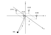
- FIG. 3 is a diagram showing an example of the arrangement of a plurality of antennas provided in the vehicle according to the present embodiment. It is a figure showing an example of the position parameter of the portable device concerning this embodiment. It is a figure showing an example of the position parameter of the portable device concerning this embodiment.
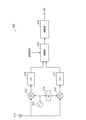
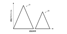
- FIG. 2 is a diagram illustrating an example of processing blocks for signal processing in the communication unit according to the present embodiment. It is a graph which shows an example of CIR based on this embodiment.
- FIG. 2 is a sequence diagram illustrating an example of the flow of ranging processing executed in the system according to the present embodiment.
- FIG. 2 is a sequence diagram illustrating an example of the flow of angle estimation processing executed in the system according to the present embodiment. It is a graph for explaining the technical problem of this embodiment. It is a graph for explaining the technical problem of this embodiment. It is a graph for explaining the technical problem of this embodiment. It is a graph for explaining the technical problem of this embodiment. It is a graph for explaining the technical problem of this embodiment. It is a graph for explaining the technical problem of this embodiment. It is a graph for explaining the technical problem of this embodiment.
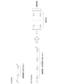
- FIG. 3 is a diagram for explaining a case where it is difficult to separate multipaths based on time information.
- FIG. 3 is a diagram for explaining multipath separation based on time information and angle information.
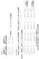
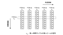
- FIG. 2 is a diagram schematically illustrating differences in delay profiles, bin mode matrices, and estimated extended signal vectors in 2D-FOCUSS and FOCUSS according to an embodiment of the present invention.
- FIG. 3 is a diagram for explaining in detail the difference in delay profiles between 2D-FOCUSS and FOCUSS according to the present embodiment.
- FIG. 3 is a diagram for explaining in detail the difference in bin mode matrices between 2D-FOCUSS and FOCUSS according to the present embodiment.
- FIG. 3 is a diagram for explaining in detail the difference between extended signal vectors in 2D-FOCUSS and FOCUSS according to the present embodiment.
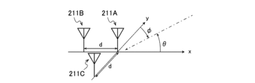
- FIG. 3 is a diagram for explaining an example of a mode vector in a direction according to the present embodiment.
- FIG. 3 is a diagram for explaining an example of a mode vector in a direction according to the present embodiment.
- FIG. 3 is a diagram for explaining an example of a mode vector in a direction according to the present embodiment.
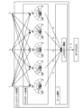
- FIG. 2 is a diagram for explaining an overview of beam space processing according to the present embodiment.
- FIG. 3 is a diagram for explaining multi-beam formation according to the present embodiment.
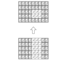
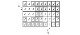
- FIG. 3 is a diagram for explaining a matrix of signals after multi-beam formation according to the present embodiment.
- FIG. 6 is a diagram for explaining a method of performing selection based on the angle domain after selection based on the time domain according to the present embodiment.
- FIG. 6 is a diagram for explaining a method of performing selection based on the time domain after selection based on the angle domain according to the present embodiment.
- FIG. 3 is a diagram for explaining a method of simultaneously performing selection based on the time domain and selection based on the angle domain according to the present embodiment.
- FIG. 3 is a diagram for explaining a method of simultaneously performing selection based on the time domain and selection based on the angle domain according to the present embodiment.
- elements having substantially the same functional configuration may be distinguished by using different alphabets after the same reference numerals.
- a plurality of elements having substantially the same functional configuration may be distinguished as wireless communication units 210A, 210B, and 210C as necessary.
- only the same reference numerals are given.
- the wireless communication units 210A, 210B, and 210C they will simply be referred to as the wireless communication unit 210.
- FIG. 1 is a diagram showing an example of the configuration of a system 1 according to an embodiment of the present invention.
- a system 1 according to the present embodiment includes a portable device 100 and a communication unit 200.
- the communication unit 200 in this embodiment is mounted on a vehicle 202.
- Vehicle 202 is an example of an object to be used by a user.
- the present invention involves a communication device on the side of the person to be authenticated and a communication device on the side of the certifier.
- the portable device 100 is an example of a communication device on the side of the person to be authenticated
- the communication unit 200 is an example of the communication device on the side of the authenticator.
- System 1 when a user (for example, a driver of a vehicle 202) carries a portable device 100 and approaches a vehicle 202, a wireless connection is established between the portable device 100 and a communication unit 200 mounted on the vehicle 202 for authentication. Communication takes place. If the authentication is successful, the doors of the vehicle 202 are unlocked, the engine is started, and the vehicle 202 becomes usable by the user.
- System 1 is also referred to as a smart entry system. Each component will be explained in order below.
- Portable device 100 is configured as any device carried by a user. Arbitrary devices include electronic keys, smartphones, wearable terminals, and the like. As shown in FIG. 1, the portable device 100 includes a wireless communication section 110, a storage section 120, and a control section 130.
- the wireless communication unit 110 has a function of performing wireless communication with the communication unit 200 mounted on the vehicle 202.
- Wireless communication section 110 receives a wireless signal from communication unit 200 mounted on vehicle 202, and transmits the wireless signal.
- Wireless communication between the wireless communication section 110 and the communication unit 200 is realized by, for example, a signal using UWB (Ultra-Wide Band).
- UWB Ultra-Wide Band
- the propagation delay time of radio waves can be measured with high precision by using radio waves with a very short pulse width of nanoseconds or less, and the propagation delay can be measured with high precision. Distance measurement based on time can be performed with high accuracy. Note that the propagation delay time is the time it takes from transmitting radio waves to receiving them.
- the wireless communication unit 110 is configured, for example, as a communication interface capable of UWB communication.
- signals using UWB can be transmitted and received as, for example, distance measurement signals, angle estimation signals, and data signals.
- the distance measurement signal is a signal that is transmitted and received in distance measurement processing, which will be described later.
- the ranging signal may be configured in a frame format that does not have a payload portion for storing data, or may be configured in a frame format that has a payload portion.
- the angle estimation signal is a signal that is transmitted and received in angle estimation processing, which will be described later.
- the angle estimation signal may have the same configuration as the ranging signal.
- the data signal is configured in a frame format with a payload portion storing data.
- the wireless communication unit 110 has at least one antenna 111.
- the wireless communication unit 110 transmits and receives wireless signals via at least one antenna 111.
- the storage unit 120 has a function of storing various information for the operation of the portable device 100.
- the storage unit 120 stores a program for operating the portable device 100, an ID (identifier) for authentication, a password, an authentication algorithm, and the like.
- the storage unit 120 includes, for example, a storage medium such as a flash memory, and a processing device that performs recording and reproduction on the storage medium.
- the control unit 130 has a function of executing processing in the portable device 100.
- the control unit 130 controls the wireless communication unit 110 to communicate with the communication unit 200 of the vehicle 202.
- the control unit 130 reads information from the storage unit 120 and writes information to the storage unit 120.
- the control unit 130 also functions as an authentication control unit that controls authentication processing performed with the communication unit 200 of the vehicle 202.
- the control unit 130 is configured by, for example, an electronic circuit such as a CPU (Central Processing Unit) and a microprocessor.
- Communication unit 200 is provided in association with vehicle 202.
- the communication unit 200 is installed in the vehicle 202, such as installed in the cabin of the vehicle 202 or built into the vehicle 202 as a communication module.
- the vehicle 202 and the communication unit 200 may be configured separately, such as by providing the communication unit 200 in a parking lot for the vehicle 202.
- the communication unit 200 can wirelessly transmit a control signal to the vehicle 202 based on the result of communication with the portable device 100 to remotely control the vehicle 202.
- the communication unit 200 includes a plurality of wireless communication sections 210 (210A to 210D), a storage section 220, and a control section 230.
- the wireless communication unit 210 has a function of performing wireless communication with the wireless communication unit 110 of the portable device 100.
- the wireless communication unit 210 receives a wireless signal from the portable device 100 and transmits the wireless signal to the portable device 100.
- the wireless communication unit 210 is configured, for example, as a communication interface capable of UWB communication.
- each wireless communication unit 210 has an antenna 211.
- Each wireless communication unit 210 transmits and receives wireless signals via the antenna 211.
- the storage unit 220 has a function of storing various information for the operation of the communication unit 200.
- the storage unit 220 stores programs for operating the communication unit 200, authentication algorithms, and the like.
- the storage unit 220 includes, for example, a storage medium such as a flash memory, and a processing device that performs recording and reproduction on the storage medium.
- the control unit 230 has a function of controlling the overall operation of the communication unit 200 and the on-vehicle equipment mounted on the vehicle 202.
- the control unit 230 controls the wireless communication unit 210 to communicate with the portable device 100.
- the control unit 230 reads information from the storage unit 220 and writes information to the storage unit 220.
- the control unit 230 also functions as an authentication control unit that controls authentication processing performed with the portable device 100.
- the control unit 230 also functions as a door lock control unit that controls the door locks of the vehicle 202, and locks and unlocks the door locks.
- the control unit 230 also functions as an engine control unit that controls the engine of the vehicle 202, and starts/stops the engine.
- the power source provided in the vehicle 202 may be a motor or the like in addition to the engine.
- the control unit 230 is configured as an electronic circuit such as an ECU (Electronic Control Unit), for example.
- position parameter estimation process to estimate a position parameter indicating the position where the portable device 100 is present.
- FIG. 2 is a diagram showing an example of the arrangement of the plurality of antennas 211 (wireless communication unit 210) provided in the vehicle 202 according to the present embodiment.
- four antennas 211 (211A-211D) are provided on the ceiling of the vehicle 202.
- Antenna 211A is provided on the front right side of vehicle 202.
- Antenna 211B is provided on the front left side of vehicle 202.
- Antenna 211C is provided on the rear right side of vehicle 202.
- Antenna 211D is provided on the rear left side of vehicle 202.
- the distance between adjacent antennas 211 is set to be one-half or less of the wavelength ⁇ of an angle estimation signal, which will be described later.
- a local coordinate system of the communication unit 200 is set as a coordinate system based on the communication unit 200.
- An example of the local coordinate system of the communication unit 200 is such that the center of the four antennas 211 is the origin, the longitudinal direction of the vehicle 202 is the X axis, the left and right direction of the vehicle 202 is the Y axis, and the vertical direction of the vehicle 202 is the Z axis.
- the coordinate system is Note that the X-axis is parallel to an axis that connects antenna pairs in the front-rear direction (for example, antenna 211A and antenna 211C, and antenna 211B and antenna 211D). Further, the Y-axis is parallel to an axis that connects antenna pairs in the left and right direction (for example, antenna 211A and antenna 211B, and antenna 211C and antenna 211D).
- the arrangement shape of the four antennas 211 is not limited to a square, but may be a parallelogram, trapezoid, rectangle, or any other arbitrary shape.
- the number of antennas 211 is not limited to four.
- FIG. 3 is a diagram showing an example of position parameters of the portable device 100 according to the present embodiment.
- the location parameter may include the distance R between the portable device 100 and the communication unit 200.
- the distance R shown in FIG. 3 is the distance from the origin of the local coordinate system of the communication unit 200 to the portable device 100.
- the distance R is estimated based on the results of transmission and reception of a ranging signal, which will be described later, between one of the plurality of wireless communication units 210 and the portable device 100.
- the distance R may be the distance from one wireless communication unit 210 that transmits and receives a ranging signal, which will be described later, to the portable device 100.
- the position parameters include the angle of the portable device 100 with respect to the communication unit 200, which is an angle ⁇ from the X axis to the portable device 100 and an angle ⁇ from the Y axis to the portable device 100, as shown in FIG. obtain.
- the angles ⁇ and ⁇ are angles formed between the coordinate axis and a straight line connecting the origin and the portable device 100 in the first predetermined coordinate system.
- the first predetermined coordinate system is the local coordinate system of the communication unit 200.
- the angle ⁇ is the angle between the straight line connecting the origin and the portable device 100 and the X-axis.
- the angle ⁇ is the angle between the straight line connecting the origin and the portable device 100 and the Y axis.
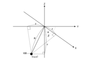
- FIG. 4 is a diagram showing an example of position parameters of the portable device 100 according to the present embodiment.
- the position parameters may include coordinates of the portable device 100 in a second predetermined coordinate system.
- the coordinate x on the X axis, the coordinate y on the Y axis, and the coordinate z on the Z axis of the portable device 100 shown in FIG. 4 are examples of such coordinates.
- the second predetermined coordinate system may be a local coordinate system of the communication unit 200.
- the second predetermined coordinate system may be a global coordinate system.
- CIR Channel Impulse Response
- the CIR is the response when an impulse is input into the system.
- the CIR is defined as the CIR when the wireless communication section of one of the portable device 100 and the communication unit 200 (hereinafter also referred to as the transmitting side) transmits a signal including a pulse as a first signal, and the other side (hereinafter also referred to as the receiving side) It is calculated based on the second signal, which is a signal corresponding to the first signal, received by the wireless communication unit of It can also be said that the CIR indicates the characteristics of the wireless communication path between the portable device 100 and the communication unit 200.
- the first signal will also be referred to as a transmitted signal
- the second signal will also be referred to as a received signal.
- the CIR may be a correlation calculation result that is a result of correlating the transmitted signal and the received signal at each specified time.
- the correlation here may be sliding correlation, which is a process of taking the correlation between the transmitted signal and the received signal while shifting their respective relative positions in the time direction.
- the CIR includes a correlation value indicating the height of the correlation between the transmitted signal and the received signal as an element for each time interval with a specified time interval.
- the prescribed time is, for example, an interval at which the receiving side samples the received signal. Therefore, the elements that make up the CIR are also called sampling points.
- the correlation value may be a complex number with IQ components. Further, the correlation value may be a complex amplitude or phase. Further, the correlation value may be power, which is the sum of squares (or square of amplitude) of complex I and Q components.
- CIR can also be understood as a set whose elements are values at each time (hereinafter also referred to as CIR values).
- CIR is a time-series change in CIR value.
- CIR is a correlation value.
- the CIR may be the received signal itself (a complex number having an IQ component) at each specified time. Further, the CIR may be the amplitude or phase of the received signal at each specified time. Further, the CIR may be a power value that is the sum of squares of the I component and Q component of the received signal for each specified time.
- a time counter is a counter that counts (typically increments) a value (hereinafter also referred to as a count value) indicating elapsed time at a predetermined time interval (hereinafter also referred to as a count period).
- the current time is calculated based on the count value counted by the time counter, the count period, and the count start time.
- synchronization When different devices have the same counting period and counting start time, it is also referred to as synchronization.
- Portable device 100 and communication unit 200 may be synchronized or asynchronous.
- each of the plurality of wireless communication units 210 may be synchronized with each other or may be asynchronous with each other.
- the specified time when calculating the CIR may be an integral multiple of the count period of the time counter. In the following description, unless otherwise specified, it will be assumed that the portable device 100 and each of the plurality of wireless communication units 210 are synchronized with each other.
- FIG. 5 is a diagram illustrating an example of processing blocks for signal processing in the communication unit 200 according to the present embodiment.
- the communication unit 200 includes an oscillator 212, a multiplier 213, a 90-degree phase shifter 214, a multiplier 215, an LPF (Low Pass Filter) 216, an LPF 217, a correlator 218, and an integrator 219. .
- LPF Low Pass Filter
- the oscillator 212 generates a signal with the same frequency as the frequency of the carrier wave that carries the transmission signal, and outputs the generated signal to the multiplier 213 and the 90-degree phase shifter 214.
- the multiplier 213 multiplies the reception signal received by the antenna 211 and the signal output from the oscillator 212, and outputs the multiplication result to the LPF 216.
- the LPF 216 outputs to the correlator 218 a signal having a frequency lower than the frequency of the carrier wave carrying the transmission signal.
- the signal input from the LPF 216 to the correlator 218 is the I component (ie, real part) of the components corresponding to the envelope of the received signal.
- the 90 degree phase shifter 214 delays the phase of the input signal by 90 degrees and outputs the delayed signal to the multiplier 215.
- Multiplier 215 multiplies the reception signal received by antenna 211 and the signal output from 90-degree phase shifter 214, and outputs the multiplication result to LPF 217.
- the LPF 217 outputs to the correlator 218 a signal having a frequency lower than the frequency of the carrier wave carrying the transmission signal.
- the signal input from the LPF 216 to the correlator 218 is the Q component (ie, the imaginary part) of the components corresponding to the envelope of the received signal.
- the correlator 218 calculates the CIR by performing a sliding correlation between the received signal, which is output from the LPF 216 and the LPF 217 and is composed of an I component and a Q component, and the reference signal.
- the reference signal here is the same signal as the transmission signal before being multiplied by the carrier wave.
- the integrator 219 integrates the CIR output from the correlator 218 and outputs the result.
- the transmitting side may transmit a signal including a preamble including a plurality of one or more preamble symbols as a transmission signal.
- a preamble is a sequence known between transmitters and receivers.
- a preamble is typically placed at the beginning of a transmitted signal.
- a preamble symbol is a pulse array that includes one or more pulses.
- a pulse array is a set of multiple pulses separated in the time direction.
- the preamble symbols are subject to integration by the integrator 219.
- the correlator 218 performs a sliding correlation between each of the parts corresponding to a plurality of preamble symbols included in the received signal and the preamble symbols included in the transmitted signal (i.e., the reference signal), so that each preamble symbol is Calculate the CIR of Then, the integrator 219 integrates the CIR for each preamble symbol with respect to one or more preambles included in the preamble, and outputs the integrated CIR.
- FIG. 6 is a graph showing an example of CIR according to this embodiment.
- the CIR shown in FIG. 6 is the CIR when it is assumed that the time when the transmitting side transmits the transmission signal is the time when the time counter starts counting.
- Such a CIR is also referred to as a delay profile.
- the horizontal axis of this graph is the delay time.
- the delay time is the elapsed time from the time when the transmitting side transmitted the transmission signal.
- the vertical axis of this graph is the absolute value of the CIR value (for example, the power value). Note that in the following explanation, CIR refers to a delay profile.
- a piece of information that constitutes information that changes over time is also referred to as a sampling point.
- a set of sampling points between zero crossing points corresponds to one pulse.
- the CIR shown in FIG. 6 includes a set 21 of sampling points corresponding to a certain pulse and a set 22 of sampling points corresponding to another pulse.
- the set 21 corresponds to, for example, signals (for example, pulses) that have arrived at the receiving side via the fast path.
- Fastpath refers to the shortest route between sending and receiving.
- Fastpath refers to a straight path between transmitting and receiving in an unobstructed environment.
- the set 22 corresponds, for example, to signals (eg, pulses) that arrive at the receiving side via a path other than the fast path. Signals that arrive via multiple paths in this way are also referred to as multipath waves.
- the receiving side detects a signal that satisfies a predetermined detection criterion among the radio signals received from the transmitting side as a signal that has reached the receiving side via the fast path.
- the receiving side estimates the position parameters based on the detected signals.
- the signal detected as the signal reaching the receiving side via the fast path is also referred to as the first arriving wave below.
- the first arriving wave can be either a direct wave, a delayed wave, or a composite wave.
- a direct wave is a signal that is directly received by the receiving side (that is, without being reflected) via the shortest path between transmitting and receiving. That is, a direct wave is a signal that reaches the receiving side via a fast path.
- a delayed wave is a signal that is indirectly received by the receiving side via a path that is not the shortest between transmitting and receiving, that is, by being reflected or the like. The delayed wave is received by the receiving side with a delay compared to the direct wave.
- a composite wave is a signal that is received by the receiving side in a state in which a plurality of signals that have passed through a plurality of different paths are combined.
- the receiving side detects a signal that satisfies a predetermined detection criterion among the radio signals received from the transmitting side as a first arriving wave.
- a predetermined detection criterion is that the power value of the CIR first exceeds a predetermined threshold. That is, the receiving side may detect a pulse corresponding to a portion of the CIR where the power value first exceeds a predetermined threshold value as the first arriving wave.
- a predetermined detection criterion is that the received power value of a received wireless signal (ie, the sum of the squares of the I and Q components of the received signal) exceeds a predetermined threshold for the first time. That is, the receiving side may detect the signal whose received power value first exceeds a predetermined threshold among the received signals as the first arriving wave.
- the signal detected as the first arriving wave is not necessarily a direct wave.
- the direct wave when a direct wave is received in a state where the delayed wave cancels out, the power value of the CIR becomes less than a predetermined threshold value, and the direct wave may not be detected as the first arriving wave. In that case, a delayed wave or a composite wave that arrives later than the direct wave will be detected as the first arriving wave.
- the communication unit 200 performs distance measurement processing.
- the distance measurement process is a process of estimating the distance between the communication unit 200 and the portable device 100.
- the distance between the communication unit 200 and the portable device 100 is, for example, the distance R shown in FIG. 3.
- the distance measurement process includes transmitting and receiving a distance measurement signal, and calculating the distance R based on the propagation delay time of the distance measurement signal.
- Propagation delay time is the time it takes from when a signal is transmitted until it is received.
- any one of the plurality of wireless communication units 210 included in the communication unit 200 transmits and receives the ranging signal.
- the wireless communication unit 210 that transmits and receives ranging signals is also referred to as a master below.
- the distance R is the distance between the wireless communication unit 210 (more precisely, the antenna 211) functioning as a master and the portable device 100.
- a plurality of ranging signals may be transmitted and received between the communication unit 200 and the portable device 100.
- the ranging signal transmitted from one device to the other device is also referred to as a first ranging signal.
- a second ranging signal is transmitted as a response to the first ranging signal. It is also called the ranging signal.
- the distance measurement signal transmitted as a response to the second distance measurement signal is transmitted as a third distance measurement signal. Also called a ranging signal.
- FIG. 7 is a sequence diagram showing an example of the flow of distance measurement processing executed in the system 1 according to the present embodiment. This sequence involves the portable device 100 and the communication unit 200. In this sequence, it is assumed that the wireless communication unit 210A functions as a master.
- the portable device 100 transmits a first ranging signal (step S102).
- the control unit 230 calculates the CIR of the first ranging signal.
- the control unit 230 detects the first arriving wave of the first ranging signal in the wireless communication unit 210A based on the calculated CIR (step S104).
- the wireless communication unit 210A transmits a second ranging signal as a response to the first ranging signal (step S106).
- the portable device 100 Upon receiving the second ranging signal, the portable device 100 calculates the CIR of the second ranging signal. Thereafter, the portable device 100 detects the first arriving wave of the second ranging signal based on the calculated CIR (step S108).
- the portable device 100 transmits a third ranging signal as a response to the second ranging signal (step S110).
- the control unit 230 calculates the CIR of the third ranging signal. Thereafter, the control unit 230 detects the first arriving wave of the third ranging signal in the wireless communication unit 210A based on the calculated CIR (step S112).
- the portable device 100 has a time INT 1 from the transmission time of the first ranging signal to the receiving time of the second ranging signal, and the time INT 1 from the receiving time of the second ranging signal to the third ranging signal. Measure the time INT 2 until the signal transmission time.
- the reception time of the second distance measurement signal is the reception time of the first arriving wave of the second distance measurement signal detected in step S108.
- the portable device 100 transmits a signal including information indicating times INT 1 and INT 2 (step S114). Such a signal is received by, for example, the wireless communication unit 210A.
- the control unit 230 controls the time INT 3 from the reception time of the first distance measurement signal to the transmission time of the second distance measurement signal, and the time INT 3 from the transmission time of the second distance measurement signal to the third distance measurement signal. Measure the time INT 4 until the signal reception time.
- the reception time of the first distance measurement signal is the reception time of the first arriving wave of the first distance measurement signal detected in step S104.
- the reception time of the third distance measurement signal is the reception time of the first arriving wave of the third distance measurement signal detected in step S112.
- control unit 230 estimates the distance R based on the times INT 1 , INT 2 , INT 3 , and INT 4 (step S116). For example, the control unit 230 estimates the propagation delay time ⁇ m using the following equation.
- control unit 230 estimates the distance R by multiplying the estimated propagation delay time ⁇ m by the speed of the signal.
- the reception time of the distance measurement signal at the beginning or end of times INT 1 , INT 2 , INT 3 , and INT 4 is the reception time of the first arriving wave of the distance measurement signal.
- the signal detected as the first arriving wave is not necessarily a direct wave.
- the reception time of the first arriving wave is longer than when the direct wave is detected as the first arriving wave. delay.
- the estimation result of the propagation delay time ⁇ m varies from the true value (the estimation result when the direct wave is detected as the first arriving wave). Then, the distance measurement accuracy decreases by the amount of variation.
- the receiving side may set the time when a predetermined detection criterion is met as the reception time of the first arriving wave. That is, the receiving side sets the time when the power value of the CIR first exceeds a predetermined threshold, or the time when the received power value of the received radio signal first exceeds a predetermined threshold, as the reception time of the first arriving wave. Good too.
- the receiving side determines the peak time of the detected first arriving wave (that is, the time when the power value is highest in the portion corresponding to the first arriving wave in the CIR, or the received power value of the first arriving wave). may be set as the reception time of the first arriving wave.
- the communication unit 200 performs angle estimation processing.
- the angle estimation process is a process for estimating the angles ⁇ and ⁇ shown in FIG.
- the angle acquisition process includes receiving an angle estimation signal and calculating angles ⁇ and ⁇ based on the reception result of the angle estimation signal.
- the angle estimation signal is a signal transmitted and received in angle estimation processing. An example of the flow of the angle estimation process will be described below with reference to FIG.
- FIG. 8 is a sequence diagram showing an example of the flow of the angle estimation process executed in the system 1 according to the present embodiment. This sequence involves the portable device 100 and the communication unit 200.
- the portable device 100 transmits an angle estimation signal (step S202).
- the control unit 230 calculates the CIR of the angle estimation signal received by each of the wireless communication units 210A to 210D.
- the control unit 230 detects the first arriving wave of the angle estimation signal for each of the wireless communication units 210A to 210D based on the calculated CIR (steps S204A to S204D).
- the control unit 230 detects the phase of the detected first arriving wave for each of the wireless communication units 210A to 210D (steps S206A to S206D).
- the control unit 230 estimates the angles ⁇ and ⁇ based on the phase of the first arriving wave detected for each of the wireless communication units 210A to 210D (step S208).
- the phase of the first arriving wave is the phase of the CIR at the reception time of the first arriving wave.
- the phase of the first arriving wave may be the phase at the reception time of the first arriving wave among the received radio signals.
- step S208 Let PA be the phase of the first arriving wave detected by the wireless communication unit 210A.
- P B be the phase of the first arriving wave detected by the wireless communication unit 210B.
- P C be the phase of the first arriving wave detected by the wireless communication unit 210C.
- PD be the phase of the first arriving wave detected by the wireless communication unit 210D.
- the antenna array phase differences Pd AC and Pd BD in the X-axis direction and the antenna array phase differences Pd BA and Pd DC in the Y-axis direction are respectively expressed by the following equations.
- angles ⁇ and ⁇ are calculated by the following equations.
- ⁇ is the wavelength of the radio wave
- d is the distance between the antennas 211.
- angles calculated based on the respective antenna array phase differences are expressed by the following equations.
- the control unit 230 calculates the angles ⁇ and ⁇ based on the calculated angles ⁇ AC , ⁇ BD , ⁇ DC , and ⁇ BA . For example, the control unit 230 calculates the angles ⁇ and ⁇ by averaging the angles calculated for each of the two arrays in the X-axis and Y-axis directions, as shown in the following equations.
- angles ⁇ and ⁇ are calculated based on the phase of the first arriving wave.
- the signal detected as the first arriving wave is not necessarily a direct wave.
- a delayed wave or a composite wave may be detected as the first arriving wave.
- the phases of the delayed wave and the composite wave are different from the phase of the direct wave, so the accuracy of angle estimation decreases by the difference.
- the angle estimation signal and the ranging signal may be the same.
- the third ranging signal shown in FIG. 7 and the angle estimation signal shown in FIG. 8 may be the same.
- the communication unit 200 can calculate the distance R and the angles ⁇ and ⁇ by receiving one wireless signal that serves as both the angle estimation signal and the second ranging signal.
- the control unit 230 performs coordinate estimation processing.
- the coordinate estimation process is a process of estimating the three-dimensional coordinates (x, y, z) of the portable device 100 shown in FIG. 4.
- the coordinate estimation process includes the following first calculation method and second calculation method. A method may be employed.
- the first calculation method is a method of calculating coordinates x, y, and z based on the results of distance measurement processing and angle estimation processing. In that case, the control unit 230 first calculates the coordinates x and y using the following equations.
- the control unit 230 uses the above relationship to calculate the coordinate z according to the following equation.
- the second calculation method is a method of calculating the coordinates x, y, and z without estimating the angles ⁇ and ⁇ .
- the position parameter may include the area where the portable device 100 exists among a plurality of predefined areas.
- the control unit 230 estimates the area where the portable device 100 exists based on the distance R estimated by the distance measurement process.
- the control unit 230 estimates the area where the portable device 100 exists based on the angles ⁇ and ⁇ estimated by the angle estimation process.
- the control unit 230 estimates the area where the portable device 100 exists based on the coordinates (x, y, z) estimated by the coordinate estimation process. .
- the control unit 230 may estimate the area where the portable device 100 is present from among a plurality of areas including the inside and outside of the vehicle 202. This makes it possible to provide detailed services, such as providing different services depending on whether the user is inside the vehicle or outside the vehicle.
- the control unit 230 specifies the area where the portable device 100 is present from among a peripheral area that is an area within a predetermined distance from the vehicle 202 and a far area that is an area that is a predetermined distance or more from the vehicle 202. Good too.
- the location parameter estimation results can be used, for example, for authentication of the portable device 100. For example, if the portable device 100 is present in an area near the driver's seat and close to the communication unit 200, the control unit 230 determines that the authentication is successful and unlocks the door.
- the technical problems of this embodiment will be explained with reference to FIGS. 9 to 12.
- 9 to 12 are graphs for explaining the technical problems of this embodiment.
- the horizontal axis is the chip length indicating the delay time
- the vertical axis is the absolute value of the CIR value (for example, the power value).
- the chip length is the time width per pulse. For example, when creating a pulse with a bandwidth of 500 MHz, the chip length is approximately 2 ns pulse width.
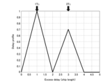
- FIG. 9 shows the CIR when a signal via the fast path arrives at a delay time of 1TC , and a signal via a route other than the fastpath arrives at a delay time of 3TC .
- the CIR waveform has a peak at each of delay times 1TC and 3TC . Therefore, it can be seen that separation of two multipath waves having a delay time of 2TC is sufficiently achieved by the CIR waveform.
- FIG. 10 shows the CIR when a signal via a fast path arrives at a delay time of 1TC , and a signal via a route other than the fastpath arrives at a delay time of 2TC .
- the first wave signal that arrives with a delay time of 1TC and the second wave signal that arrives with a delay time of 2TC are in phase.
- the CIR waveform has a peak at delay time 1TC
- the signal that arrived at delay time 1T C and the signal that arrived at delay time 2T C are combined in phase and appear as one waveform. Therefore, it can be seen that it is difficult to separate two multipath waves with a delay time of 1TC apart from each other using a CIR waveform.
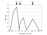
- FIG. 11 shows the CIR when a signal via the fast path arrives at a delay time of 1.2TC , and a signal via a route other than the fastpath arrives at delay times of 1.7TC and 3.6TC. has been done.
- the first wave signal that arrives with a delay time of 1.2T C and the second wave signal that arrives with a delay time of 1.7T C have opposite phases.
- the CIR waveform peaks at delay times of 1.2TC and 3.6TC .
- a second peak appears near the delay time of 2.2TC . This deviates significantly from the true delay time of 1.7TC . Therefore, it can be seen that it is difficult to separate two multipath waves with a delay time of 0.5 T C apart from each other using a CIR waveform.
- the delay time at which the peak occurs in the CIR waveform may vary from the original delay time. Therefore, the delay time detected as the reception time of the first arriving wave may vary from the original delay time. In that case, the distance measurement accuracy will decrease by the amount of variation.
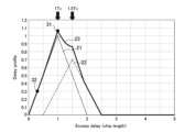
- FIG. 12 shows a CIR waveform 23 when a signal via a fast path arrives at a delay time of 1TC , and a signal via a route other than the fastpath arrives at a delay time of 1.5TC .
- the CIR waveform 21 is a CIR waveform when a signal via the fast path is received alone with a delay time of 1TC .
- the CIR waveform 22 is a CIR waveform when a signal via a route other than the fast path is received alone at a delay time of 1.5TC . Note that the first wave signal that arrives with a delay time of 1TC and the second wave signal that arrives with a delay time of 2TC are out of phase by 90 degrees.
- a delayed wave or a composite wave may be detected as the first arriving wave.
- a composite wave is detected as the first arriving wave.
- the phase of the delayed wave and the composite wave is different from the phase of the direct wave, so the angle estimation accuracy is reduced by the difference.
- the portable device 100 and the communication unit 200 detect the first arriving wave through a process described in detail below. As an example, a case will be described below in which the main body that detects the first arriving wave is the communication unit 200. The processing described below may be executed by the portable device 100.
- the PN correlation method is a method of calculating CIR by transmitting a signal consisting of a random sequence such as a PN sequence signal shared between the transmitting side and the receiving side, and calculating the sliding correlation between the transmitted signal and the received signal.
- the PN sequence signal is a signal in which 1's and 0's are arranged almost randomly.
- a PN sequence signal u(t) of unit amplitude is transmitted as a transmission signal (for example, a preamble symbol of a ranging signal and an angle estimation signal).
- the unit amplitude is a specified amplitude known between transmitting and receiving.
- the antenna on the receiving side receives an L-wave multipath wave as a signal corresponding to the transmission signal transmitted from the transmitting side.
- a multipath wave is a signal that is received by the receiving side via multiple paths. That is, when the transmitter transmits one signal, the receiver receives L signals via a plurality of routes.
- the received signal x(t) is expressed by the following equation.
- t is time.
- h i is the complex response value of the i-th multipath wave.
- T 0i is the propagation delay time of the i-th multipath wave.
- f is the frequency of the carrier wave of the transmission signal.
- v(t) is internal noise. Internal noise is noise generated inside the circuit on the receiver side.
- the correlation with the received signal x(t) is calculated while shifting the time of the known transmitted signal u(t) on the receiver side, as shown in the following equation.
- u * () is the complex conjugate of u().
- z( ⁇ ) is also referred to as a delay profile.
- 2 is also referred to as a power delay profile.
- ⁇ is the delay time.
- the delay profile of the multipath wave of the L wave is expressed by the following equation.
- r( ⁇ ) is the autocorrelation function of the PN sequence signal.
- An autocorrelation function is a function that correlates a signal with the signal itself. r( ⁇ ) is given by the following equation.
- n( ⁇ ) is an internal noise component.
- n( ⁇ ) is given by the following equation.
- the data vector z is expressed as in the following equation.
- r( ⁇ ) is called a distance mode vector.
- a 0 is also called a mode matrix.
- S0 is also called a signal vector.
- the data vector z is transformed into a format that includes the matrix product of A and s.
- T 1 , T 2 , . . . , T N represent N delay times to be searched.
- T 1 , T 2 , . . . , T N are also referred to as delay time bins.
- the delay time bin is an example of a set time. Note that N>>L.
- A is also referred to as a delay time bin mode matrix.
- the delay time bin mode matrix is a matrix composed of a plurality of elements representing a delay profile when it is assumed that a signal is received in each of a plurality of delay time bins.
- r(T 1 ) which is an element of the delay time bin mode matrix A, is the delay profile of the signal when it is assumed that the signal is received at time T 1 .
- the extended signal vector is a vector consisting of a plurality of elements representing the presence or absence of a signal for each delay time bin, as well as the amplitude and phase of the signal.
- the delay profile z is modeled in the form of As+n. Therefore, by solving an underdetermined problem in which the unknown number is N and the condition number is M (M ⁇ N), it is possible to obtain the extended signal vector s.
- the control unit 230 estimates the reception time of the first arriving wave based on delay time bins corresponding to multiple elements in the extended signal vector s.
- a non-zero element of the extended signal vector indicates that a signal exists in the delay time bin corresponding to the non-zero element.
- a zero element in the extended signal vector indicates that no signal exists in the delay time bin corresponding to the zero element. Therefore, the control unit 230 estimates the delay time bin corresponding to a non-zero element among the delay time bins corresponding to a plurality of elements in the extended signal vector s as the reception time of the first arriving wave.
- the control unit 230 estimates a sparse solution of the extended signal vector s, and estimates a delay time bin corresponding to a non-zero element of the estimated sparse solution as the reception time of the first arriving wave.
- a sparse solution is a vector in which only a predetermined number of elements are non-zero.
- the control unit 230 determines that a pulse corresponding to the element exists. Estimation may be performed as follows. Even in this case, according to the estimation method described later, it is possible to eliminate the influence of noise and realize highly accurate estimation. On the other hand, the control unit 230 may determine whether non-zero elements are noise or not, and may perform estimation by regarding elements determined to be noise as zero.
- the resolution of the signal determined by the sparsely reconstructed model is determined by the size of N (ie, the number of elements of the expanded signal vector s) when modeling in the sparsely reconstructed model. Therefore, by increasing the number N during sparse reconstruction, it becomes possible to separate multipath waves with a finer resolution than CIR. Therefore, in this embodiment, the number N of delay time bins is made larger than the number M of sampling of the received signal. In other words, in this embodiment, the time interval of N delay time bins T 1 , T 2 , ..., TN is smaller than the time interval of M discrete delay times ⁇ 1 , ⁇ 2 , ..., ⁇ M. short. With this configuration, it is possible to separate multipath waves with a resolution finer than the sampling interval of the received signal. As a result, it becomes possible to obtain the reception time of the first arriving wave with a finer resolution than CIR.
- the control unit 230 uses a compressed sensing algorithm to estimate an expanded signal vector s that is a sparse solution.
- the compressed sensing algorithm is an algorithm that assumes that the unknown vector is a sparse vector and estimates the unknown vector based on linear observation of the unknown vector.
- the extended signal vector s is an example of an unknown vector.
- Linear observation means multiplying an unknown vector by a coefficient to obtain the result.
- the bin mode matrix A is an example of a coefficient.
- the delay profile z is an example of linear observation.
- Control unit 230 may employ any of these compressed sensing algorithms.
- FOCUSS Fluorescence Underdetermined System Solver
- ISTA Iterative Shrinkage Thresholding Algorithm
- FISTA Fast ISTA
- Control unit 230 may employ any of these compressed sensing algorithms.
- FOCUSS is an algorithm that assumes an initial value for an unknown vector and iteratively estimates the unknown vector using a general inverse matrix and a weight matrix.
- FOCUSS can accurately estimate unknown vectors with a small number of iterations by using a general inverse matrix and a weight matrix.
- FOCUSS can accurately estimate unknown vectors with a small number of iterations by using a general inverse matrix and a weight matrix.
- the problem of estimating the extended signal vector s that is a sparse solution from the delay profile z is an underdetermined problem with N unknowns and M conditions (M ⁇ N). Therefore, a solution must be found by adding another condition.
- a minimum norm solution is obtained by adding a condition that the norm of the extended signal vector s is minimum. Note that the norm is the length of a vector.
- the minimum norm solution s mn is obtained by multiplying the delay profile z by the general inverse matrix of the delay time bin mode matrix A, as shown in the following equation.
- the general inverse matrix may be a Moore-Penrose general inverse matrix.
- a ⁇ is the general inverse matrix of the delay time bin mode matrix A.
- the general inverse matrix A - of the delay time bin mode matrix A is expressed by the following equation.
- the delay time bin mode matrix A is multiplied by the general inverse matrix A - of the delay time bin mode matrix A, so the delay time bin mode matrix A does not disappear completely, so the extended signal vector which is a sparse solution is used as the minimum norm solution s mn .
- a vector similar to s is calculated. Note that the minimum norm solution s mn becomes the initial value s 0 of FOUCSS.
- the minimum norm solution s mn is not a sparse solution. Therefore, as estimating the sparse solution of the extended signal vector s, the control unit 230 estimates a weighted minimum norm solution, which is a vector that minimizes the norm of a weighted vector of the extended signal vector s. By estimating a weighted minimum norm solution, it is possible to estimate a sparse solution.
- the weighted minimum norm solution is expressed by the following equation.
- W is a weight matrix.
- the weight matrix W is typically a diagonal matrix. That is, the problem of finding the weighted minimum norm solution of the extended signal vector s is described as the following equation.
- control unit 230 calculates the weighted minimum norm solution of the extended signal vector s by repeatedly calculating equations (36), (37), and (38) shown in STEP 1 to STEP 3 below. presume.
- k is the number of iterations.
- s k is a candidate for the weighted minimum norm solution.
- (AW K ) - is the general inverse matrix of AW k .
- the initial value of s k is given by the following equation as the minimum norm solution s mn .
- the control unit 230 repeatedly executes STEP 1 to STEP 3 above.
- STEP1 to STEP3 may be repeatedly executed until s k converges.
- STEP1 to STEP3 may be repeatedly executed a predetermined number of times. This makes it possible to estimate the extended signal vector s as a weighted minimum norm solution that is closer to the true value. This point will be explained below.
- equation (40) is converted to the following equation.
- W k (AW k ) - A is a matrix that does not change s, such as a unit matrix
- s k and s will be equal.
- W k (AW k ) - A is a matrix that does not change s, such as a unit matrix
- s k and s will be equal.
- the control unit 230 may obtain the general inverse matrix (AW k ) ⁇ of AW k by performing singular value decomposition. At this time, the control unit 230 may obtain (AW k ) ⁇ using, for example, TSVD (Truncated singular value decomposition).
- control unit 230 performs singular value decomposition of AW k into a format including a diagonal matrix consisting of singular values having values larger than a predetermined threshold value in equation (37) of STEP 2 above, and then calculates (AW k ) - is calculated.
- AW k is subjected to singular value decomposition as shown in the following equation.
- S t is a diagonal matrix consisting of t non-zero singular values.
- U t is a matrix consisting of t-column left singular vectors corresponding to S t .
- V t is a matrix consisting of t-column right singular vectors corresponding to S t .
- t is the number of dimensions of the signal subspace.
- a signal subspace is a space consisting of signals whose power is higher than a threshold.
- V t H is obtained by taking the complex conjugate transpose of the matrix V t , and is also called the adjoint matrix of V t .
- (AW k ) - is determined by the following equation.
- S t includes t non-zero singular values, the number of dimensions of the signal subspace. That is, S t is a diagonal matrix consisting of t singular values larger than a predetermined threshold. And t is equal to the number L of multipath waves. Therefore, by finding the general inverse matrix using only the singular values belonging to the signal subspace (that is, taking large values) as described above, it is possible to reduce the influence of noise. This is because singular values that do not belong to the signal subspace (that is, take small values) correspond to noise. By reducing the influence of noise, it becomes possible to stably and accurately obtain a general inverse matrix even under the influence of noise.
- control unit 230 may use the following equation (45) instead of equation (44) in STEP 2 above.
- ⁇ in Equation (45) is a positive minute amount.
- I is an identity matrix.
- ⁇ is also referred to as a regularization parameter.
- the regularization parameter even if A k A k H is not regular, by making A k A k H + ⁇ I regular, A k A k H can be It becomes possible to obtain the inverse matrix (A k A k H ) -1 . Furthermore, by using the regularization parameter, convergence of S k can be more easily realized. Note that the regularization parameter in FOCUSS is mentioned in the above-mentioned non-patent document.
- control unit 230 may use TSVD to obtain the inverse matrix (A k A k H ) ⁇ 1 of A k A k H. At that time, the control unit 230 decomposes A k A k H into a format including a diagonal matrix consisting of singular values having values larger than the first threshold value in the above formula (44), and then (A k A k H ) ⁇ 1 is calculated. A k A k H is subjected to singular value decomposition as shown in the following equation.
- TSVD Truncated Eigen Value Decomposition
- threshold processing may be performed.
- the threshold value processing is a process in which elements below a predetermined threshold value are set to 0.
- the control unit 230 may set to zero the elements included in the weight matrix Wk that are equal to or less than a predetermined threshold in Equation (36) of STEP 1 above.
- threshold processing shown in the following equation may be performed.
- w k (i) is the i-th diagonal component of the weight matrix W k .
- s k-1 (i) is the i-th component of the extended signal vector s k-1 .
- max is the maximum size among the elements included in s k-1 (i). 10 ⁇ 5
- max is an example of a threshold value.
- control unit 230 uses FOCUSS as the compressed sensing algorithm to estimate the extended signal vector s that is a sparse solution.
- the extended signal vector s can be estimated with high accuracy, and in turn, it is possible to improve the accuracy of estimating the distance between devices.
- FOCUSS is a process that separates multipaths based on time information (distance information), when the difference in propagation delay time (sometimes simply referred to as delay time) of multipath waves is extremely small, It may be difficult to separate multipaths.
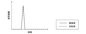
- FIG. 13 shows a graph representing the signal strength of the received signal along the time axis.
- the propagation delay time difference between the direct wave and the reflected wave is extremely small, the signal strengths of the two overlap as shown in FIG. 13, making it difficult to separate the two based on time information.
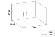
- FIG. 14 shows a graph expressing the signal strength of the received signal using the time axis and the arrival angle axis. As shown in FIG. 14, even if the propagation delay time difference between the direct wave and the reflected wave is extremely small, if the angles of arrival of the two are different, it is possible to easily separate the two.
- the technical idea according to the present embodiment was conceived with attention to the above points, and is intended to improve the accuracy of estimating distances and angles between devices.
- control unit 230 may estimate the extended signal vector s using 2D-FOCUSS instead of the FOCUSS described above.
- the communication unit 200 is basically required to include a plurality of antennas 211.
- the antenna 211 is provided movably, by receiving signals while moving the single antenna 211, signal processing as described later is performed as if the signals were virtually received by multiple antennas 211. It is also possible to do so.
- FOCUSS is a type of compressed sensing algorithm that estimates the extended signal vector s using a delay time bin mode matrix including time information information.
- the delay time bin mode matrix A in FOCUSS is expressed, for example, by the following equation (49).
- 2D-FOCUSS is a type of compressed sensing algorithm that estimates an extended signal vector s using a bin mode matrix that includes time information and angle information.
- the bin mode matrix A in 2D-FOCUSS is expressed, for example, by the following equation (50).
- N in the above equations (49) and (50) represents the number of propagation delay time bins.
- P in the above formula (50) represents the number of arrival angle bins.
- a(T n , ⁇ p ) in the above formula (50) represents a mode vector.
- a( ⁇ p ) is a vector (also referred to as a direction mode vector) representing the phase relationship of the received signals between the antennas 211 when signals from the arrival direction ⁇ p are received by the plurality of antennas 211.
- r(T n ) is a vector (also referred to as a time mode vector) consisting of an autocorrelation function of the transmitted signal having a peak at time T n .
- processing such as iterative calculations in 2D-FOCUSS is basically the same as in FOCUSS.
- the above-mentioned equations (36) to (38) are repeatedly calculated to estimate the weighted minimum norm solution of the extended signal vector s.
- 2D-FOCUSS and FOCUSS have different input delay profiles and bin mode matrices, and output (estimated) extended signal vectors.
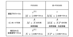
- FIG. 15 is a diagram schematically showing the differences in delay profiles, bin mode matrices, and estimated extended signal vectors in 2D-FOCUSS and FOCUSS.
- the delay profile z (k) in FOCUSS is an M ⁇ 1 column vector
- the delay profile z in 2D-FOCUSS is an MK ⁇ 1 column vector
- M represents the number of delay time samples
- K represents the number of antennas 211 (hereinafter also referred to as elements) provided in the communication unit 200.
- k represents an arbitrary numbered element (k-th element) among the plurality of elements.
- the delay time bin mode matrix A in FOCUSS is an M ⁇ N matrix that includes time information
- the bin mode matrix A in 2D-FOCUSS is an MK ⁇ N matrix that includes time information and angle information. It is a matrix of NP.
- N the number of propagation delay time bins
- P the number of arrival angle bins
- the enhanced signal vector s (k) estimated in FOCUSS is an N ⁇ 1 column vector
- the enhanced signal vector s estimated in 2D-FOCUSS is an NP ⁇ 1 column vector. It is a column vector.
- the delay profile z (k) in FOCUSS includes M delay profiles sampled at delay times ⁇ 1 to ⁇ M as elements.
- the delay profile z in 2D-FOCUSS includes M ⁇ K delay profiles sampled at delay times ⁇ 1 to ⁇ M for the first to kth elements, respectively, as shown in the lower part of FIG.
- the delay profile z in 2D-FOCUSS may be the result of calculating the correlation between the second signal and the first signal for each specified time and antenna 211.
- the delay time bin mode matrix A in FOCUSS is, as shown in the upper part of FIG . It includes M ⁇ N elements in which an autocorrelation function is defined that simulates the delay profile when Note that instead of the autocorrelation function that simulates the delay profile described above, a delay profile measured in advance may be used.
- the bin mode matrix A in 2D-FOCUSS is a matrix composed of a plurality of elements representing the correlation calculation results when it is assumed that each of the plurality of antennas 211 receives a signal at each of a plurality of set times and set angles. It may be.
- the extended signal vector s (k) estimated in FOCUSS includes N bins corresponding to delay times T 1 to T N , as shown in the upper part of FIG.
- the extended signal vector s (k) estimated in FOCUSS is zero except for the bin where the signal exists.
- the extended signal vector s estimated in 2D-FOCUSS has N ⁇ P bins corresponding to delay times T 1 to T N and angles of arrival ⁇ 1 to ⁇ P , as shown in the lower left side of FIG. include.
- s np represents a complex amplitude signal with delay time T n and arrival angle ⁇ p .
- the extended signal vector s estimated in 2D-FOCUSS is also zero in bins other than those in which the signal exists.
- control unit 230 calculates the time and angle corresponding to the element with the earliest delay time among the non-zero elements (non-zero bins) in the extended signal vector s estimated using 2D-FOCUSS. It may also be regarded as the reception time and arrival angle.
- control unit 230 estimates the earliest setting time as the reception time of the second signal among the setting times corresponding to non-zero elements among the sparse solutions of the estimated extended signal vector s, and uses the earliest setting time as the reception time of the second signal.
- the set angle corresponding to the non-zero element corresponding to may be estimated as the arrival angle of the second signal.
- control unit 230 estimates the reception time and arrival angle of the second signal by making the estimated extended signal vector s into a matrix based on the set time and set angle, and performs an amplitude peak search on the matrix. You may.
- the lower right side of FIG. 18 shows an N ⁇ P matrix obtained by converting the estimated extended signal matrix s based on the delay time and the angle of arrival by the control unit 230.
- the control unit 230 may perform an amplitude peak search on the matrix, and estimate the delay time and arrival angle corresponding to the element in which the peak is detected as the reception time and arrival angle of the signal, respectively.
- control unit 230 may estimate the delay time and arrival angle corresponding to the element that detected the peak with the largest amplitude as the reception time and arrival angle of the signal, respectively. good.
- Equation (51) the mode vector in the direction of the signal represented by the dashed line is expressed as shown in Equation (51) below. be done.
- each element of the mode vector in the direction shown by the above equation (51) represents a phase difference with the reference element (for example, the antenna 211A (first element)).
- the arrival angle of the signal estimated using 2D-FOCUSS is not limited to the one-dimensional angle ( ⁇ ).
- the bin mode matrix A in 2D-FOCUSS is as follows. It may be changed as shown in formula (52). In this case, each office mode matrix A becomes a matrix of ML ⁇ NPU.
- the mode vector in the direction is expressed as in the following equation (53).
- the directional mode vector and bin mode matrix according to this embodiment can be flexibly modified according to the arrangement of elements.
- the arrival angle of the signal estimated using 2D-FOCUSS may be a three-dimensional angle.
- the control unit 230 estimates the position parameter based on the first arriving wave detected by the process described above.
- the control unit 230 estimates the distance R between the portable device 100 and the communication unit 200 based on the reception time of the first arriving wave estimated by the process described above.
- the method for estimating the distance R is as described above with reference to FIG.
- the portable device 100 calculates the CIR regarding the second ranging signal and performs sparse reconstruction and FOCUSS. Then, the portable device 100 measures the time INT 1 based on the estimated reception time of the first arriving wave of the second ranging signal.
- the communication unit 200 calculates the CIR regarding the first ranging signal, and performs sparse reconstruction and 2D-FOCUSS. Then, the communication unit 200 measures the time INT 3 based on the estimated reception time of the first arriving wave of the first ranging signal. Similarly, the communication unit 200 calculates the CIR regarding the third ranging signal, and performs sparse reconstruction and 2D-FOCUSS. Then, the communication unit 200 measures the time INT 4 based on the estimated reception time of the first arriving wave of the third ranging signal.
- control unit 230 estimates the propagation delay time based on the times T 1 to T 4 and estimates the distance R. As explained above, since the reception time of the first arriving wave can be searched with a finer resolution than CIR, it is possible to improve the ranging accuracy accordingly.
- the communication unit 200 can estimate the arrival angle of the first arriving wave by implementing 2D-FOCUSS.
- FIG. 22 is a flowchart illustrating an example of the flow of position parameter estimation processing executed by the communication unit 200 according to the present embodiment.
- the control unit 230 first calculates a delay profile using the PN correlation method (step S302). Next, the control unit 230 converts the delay profile into a format including a matrix product of the bin mode matrix and the extended signal vector by sparse reconstruction (step S304). Next, the control unit 230 estimates an extended signal vector that is a weighted minimum norm solution using 2D-FOCUSS (step S306). Then, the control unit 230 estimates the position parameter based on the estimated extended signal vector (step S308).
- the transmitting side can transmit a signal including a plurality of preambles including one or more preamble symbols as a transmission signal.
- the receiving side can calculate the CIR for each preamble symbol by correlating each portion of the received signal corresponding to a plurality of preamble symbols with the preamble symbol at regular intervals.
- 2D-FOCUSS may be applied to the CIR after integrating the CIR for each preamble symbol. That is, the control unit 230 converts the CIR into a format that includes the matrix product of the bin mode matrix and the extended signal vector, and converts the CIR after the integration by multiplying the CIR of each preamble symbol into the bin mode matrix and the extended signal vector. It may be converted to a format that includes the matrix product of . Then, a sparse solution of the extended signal vector s is estimated by 2D-FOCUSS, and the reception time of the first arriving wave is estimated.
- 2D-FOCUSS may be applied to the CIR for each preamble symbol.
- the final extended signal vector s may be estimated by integrating the extended signal vectors s estimated for each preamble symbol. That is, the control unit 230 estimates the reception time and arrival angle of the first arriving wave based on the extended signal vector s, which is the result of integrating the extended signal vector s for each of the CIRs for each of the plurality of preambles. , the reception time and arrival angle of the first arriving wave may be estimated based on the integrated extended signal vector s.
- the CIR may be calculated for each pulse.
- 2D-FOCUSS may be applied to the CIR after integrating the CIR for each pulse, or may be applied to the CIR for each pulse.
- the CIR may be calculated for the entire preamble.
- 2D-FOCUSS may be applied to the CIR calculated for the entire preamble.
- FOCUSS may be applied to part of the CIR.
- 2D is applied to a vector (hereinafter also referred to as a partial vector) consisting of elements corresponding to some setting times and setting angles among the elements for each setting time and setting angle included in the extended signal vector s.
- - FOCUSS may be applied.
- the control unit 230 estimates a sparse solution of the partial vector by estimating a sparse solution of the extended signal vector s. That is, the control unit 230 estimates a weighted minimum norm solution, which is a vector that minimizes the norm of a vector obtained by weighting the partial vectors.
- the calculation load can be reduced compared to the case where 2D-FOCUSS is applied to the entire CIR.
- the purpose is to detect the first arriving wave
- a partial vector consisting of elements corresponding to the set time near the reception time of the first arriving wave and the set angle near the arrival angle is selected.
- 2D-FOCUSS is applied to the target.
- a strong correlation is obtained only at the delay time and angle of arrival where the pulse array of the transmitted signal and the pulse array of the received signal completely match, and the correlation is low in other parts. Therefore, even if 2D-FOCUSS is applied only to a portion of the CIR near the reception time and angle of arrival of the first arriving wave, the detection accuracy of the first arriving wave can be maintained.
- 2D-FOCUSS two-dimensional estimation of distance and angle is performed. Estimation of two or more dimensions, such as 2D-FOCUSS, requires more calculation time than one-dimensional estimation.
- control unit 230 can reduce calculation time by performing beam space (also called subspace) processing as preprocessing for an estimation algorithm such as 2D-FOCUSS. .
- the beam space processing mentioned above is a process of forming a beam in the direction of arrival of the signal, and can be said to be a process of obtaining a signal with the main beam direction emphasized by applying spatial filters with different strengths and weaknesses depending on the direction of arrival of the signal. .
- FIG. 23 is a diagram for explaining an overview of beam space processing according to this embodiment.
- the control unit 230 may perform beam space processing on the delay profiles z 1 to z K obtained from the K elements and input the selected signals y 1 to y B to the 2D-FOCUSS. .
- control unit 230 performs multi-beam forming on the delay profiles z 1 to z 3 and selects the signals y 2 and y 5 whose magnitude exceeds the threshold value among the obtained signals y 1 to y 5.
- 3 is the input of 2D-FOCUSS.
- the number of inputs to the estimation algorithm can be reduced compared to the case where beam space processing is not performed, and the calculation time of the estimation algorithm can be significantly reduced.
- FIG. 24 is a diagram for explaining multi-beam formation according to this embodiment.
- the control unit 230 may perform multi-beam forming by using arbitrary weights w 1 to w 3 for delay profiles z 1 to z 3 , for example, as shown in FIG. 24.
- the control unit 230 can flexibly set the direction of the beam by adjusting the phase of the weights w 1 to w 3 and the shape of the beam (beam pattern) by adjusting the amplitude of the weights w 1 to w 3 . .
- Multi-beam forming methods are broadly classified into fixed pattern type and adaptive type.
- the fixed pattern type is a method of forming a plurality of beams oriented in arbitrary directions, as shown in FIG. 23, by giving the amplitude and phase of the weight w in advance.
- control unit 230 may apply any one of a uniform distribution, a binomial distribution, a Chebyshev distribution, or a Taylor distribution to the amplitude of the weight w.
- the adaptive type is a method of determining the phase and amplitude of the weight w based on the delay profiles z 1 to z K.
- the adaptive type When using the adaptive type, it is theoretically possible to form an appropriate beam pattern in an appropriate direction depending on the radio wave environment. Therefore, the adaptive type has the advantage that it can direct the beam in the direction of arrival of the signal while removing noise and interference waves, and if it can form the beam accurately, it can direct the beam in the direction of arrival of the true signal.
- Examples of the adaptive type include an eigenvector beam space method in which the weight w is an eigenvector obtained by eigenvalue decomposition of the delay profiles z 1 to z K , and a method using a DCMP (Directionally Constrained Minimization of Power) adaptive array.
- DCMP Directionally Constrained Minimization of Power
- control unit 230 can also perform dynamic multi-beam formation, such as by selectively using a fixed pattern type or an adaptive type depending on the radio wave environment.
- control unit 230 selects a signal whose magnitude (for example, norm if y b is a vector) exceeds a threshold value from among the signals y b that have passed through the formed beam. Good too.
- control unit 230 may select N signals y b in order from the one with the largest magnitude.
- control unit 230 may replace the magnitude of the signal y b with an eigenvalue obtained by eigenvalue decomposition.
- control unit 230 can further reduce calculation time by selecting the signal yb based not only on the angular domain but also on the time domain.
- FIG. 25 is a diagram for explaining the signal matrix after multi-beam formation according to this embodiment.
- the column vector is the signal vector of the b-th beam
- the row vector is the signal vector of the m-th time sample.
- Beam selection includes time-domain selection followed by angular-domain selection, angular-domain selection followed by time-domain selection, and time-domain selection followed by angular-domain selection.
- One method is to do it simultaneously.
- a configuration in which angular domain selection is performed after time domain selection is more suitable for systems with high time domain resolution. Specifically, when the time domain resolution is high, there is a high possibility that the noise in the time domain and the true signal can be separated, so it is possible to remove noise accurately by selecting the time domain first. can. In other words, in the later selection of the angular region, data from which noise has already been removed will be processed, so the angular region can be selected with higher precision.
- FIG. 26 is a diagram for explaining a method of performing selection based on the angle domain after selection based on the time domain according to the present embodiment.
- control unit 230 first selects a row vector whose norm in the time domain exceeds the threshold.
- FIGS. 26 to 28 selected objects are shown in solid color, and non-selected objects are shown in dots.
- control unit 230 may determine each corresponding cluster as a separate arriving wave. In this way, when two or more waves exist, the control unit 230 does not need to select the time-delayed signal. This can eliminate unnecessary calculations.
- control unit 230 selects a column vector whose norm of the column vector in the angular domain exceeds the threshold value in the matrix composed of only the selected row vectors.
- control unit 230 may perform selection using different threshold values in the time domain and the angle domain.
- a configuration in which time domain selection is performed after angular domain selection is more suitable in a system with high resolution in the angular domain. Specifically, when the resolution of the angular domain is high, there is a high possibility that the noise in the angular domain and the true signal can be separated, so it is possible to remove noise accurately by selecting the angular domain first. can. In other words, in the later time domain selection, data from which noise has already been removed will be processed, so the time domain selection can be performed with higher precision.
- FIG. 27 is a diagram for explaining a method of performing selection based on the time domain after selection based on the angle domain according to the present embodiment.
- control unit 230 first selects a column vector in the angular domain whose norm exceeds the threshold value.
- control unit 230 does not need to select a column vector in the predefined angle region. This can eliminate unnecessary calculations. Such control is particularly useful when the positional information of shielding objects around the communication unit is known.
- control unit 230 selects a row vector whose norm of the time-domain row vector in the matrix composed of only the selected column vectors exceeds the threshold value.
- control unit 230 may perform selection using different threshold values in the time domain and the angle domain.
- control unit 230 When adopting this method, the control unit 230 only needs to select elements in which the size of each element of the signal matrix exceeds a threshold value.
- control unit 230 may select N elements in descending order of size.
- control unit 230 can also select a non-rectangular range in the time-spatial domain, as shown in FIG. 28, unlike the two methods described above. This makes it possible to select elements with a higher degree of freedom than when selecting time or angle sequentially.
- the control unit 230 may determine cluster C1 and cluster C2 as separate arriving waves. Moreover, when two or more waves exist, the control unit 230 may not select the time-delayed signal. This can eliminate unnecessary calculations.
- the beam space processing according to this embodiment has been described above. According to the beam space processing according to this embodiment, by limiting the information input to the estimation algorithm, it is possible to significantly reduce calculation time.
- the inputs to 2D-FOCUSS are the delay profile z and the bin mode matrix A, as described above.
- the inputs to 2D-FOCUSS are the delay profile z b and the bin mode matrix B.
- control unit 230 performs multi-beam formation by signal conversion as shown in the following equation (55) using weights (matrix) defined in the following equation (54), and then performs multi-beam formation using the following equation (56). ), a delay profile zb and a bin mode matrix B are obtained by performing signal selection as shown in FIG. Note that F in the following equations (54) to (56) is the number of beams generated in multi-beam formation.
- the control unit 230 inputs the delay profile z b and the bin mode matrix B obtained as described above to the 2D-FOCUSS and estimates the extended signal vector s.
- the bin mode matrix B and the extended signal vector s correspond to elements N corresponding to delay times T 1 to T N and angles of arrival ⁇ 1 to ⁇ P , as described with reference to FIGS. 17 and 18. It has a bin containing element P.
- the control unit 230 may determine the setting range of bins in the bin mode matrix B and the extended signal vector s based on the results of the beam space processing.
- control unit 230 may determine the bin setting range based on the time and angle range selected in the beam space processing. According to this, it is possible to further reduce the number of bins (N and P) and further reduce the amount of calculation.
- the beam space processing according to this embodiment is applicable not only to 2D-FOCUSS but also to various N-dimensional estimation algorithms (N ⁇ 2) that estimate two or more parameters simultaneously.
- Examples of the above parameters include distance, speed, acceleration, dielectric constant, etc.
- the input to the N-dimensional estimation algorithm is not limited to UWB signals, but may be any wave such as radio waves, ultrasonic waves, light, etc.
- the input to the N-dimensional estimation algorithm may be a reflected wave from a radar or the like.
- the l0 norm refers to the case where the multiplier p in the lp norm is 0.
- the lp norm is defined by the following equation.
- the l0 norm is the number of non-zero components of a vector.
- the method of repeatedly executing Equations (36) to (38) mentioned in the above embodiment is a method of minimizing the l0 norm as a weighted minimum norm solution of the expansion vector s.
- the control unit 230 may minimize the lp norm as a weighted minimum norm solution of the expansion vector s.
- the control unit 230 may use the following equation instead of STEP 1 above.
- p here is a constant of 0 or more and 1 or less.
- the above formula (59) is the same as formula (36). That is, the control unit 230 may estimate the weighted minimum norm solution by setting p to 0 in the above equation (59).
- the control unit 230 calculates the CIR, detects the first arriving wave, and estimates the position parameter, but the present invention is not limited to such an example. At least one of these processes may be executed by the wireless communication unit 210. For example, each of the plurality of wireless communication units 210 may calculate the CIR and detect the first arriving wave based on the received signal received by each of the wireless communication units 210. Furthermore, the estimation of the positional parameters may be performed by, for example, the wireless communication unit 210 functioning as a master.
- the communication unit 200 may calculate the angles ⁇ and ⁇ by performing beamforming using the plurality of antennas 211. In that case, the communication unit 200 scans the main lobes of the plurality of antennas 211 in all directions, determines that the portable device 100 is present in the direction where the received power is greatest, and calculates the angles ⁇ and ⁇ based on this direction. .
- the local coordinate system is a coordinate system having a coordinate axis parallel to the axis connecting the antenna pair, but the present invention does not apply to such an example.
- the local coordinate system may be a coordinate system having coordinate axes that are not parallel to the axis connecting the antenna pair.
- the origin is not limited to the center of the plurality of antennas 211.
- the local coordinate system according to this embodiment may be arbitrarily set based on the arrangement of the plurality of antennas 211 included in the communication unit 200.
- the person to be authenticated is the portable device 100 and the authenticator is the communication unit 200, but the present invention is not limited to such an example.
- the roles of portable device 100 and communication unit 200 may be reversed.
- the portable device 100 may specify the location parameter.
- the roles of the portable device 100 and the communication unit 200 may be dynamically exchanged.
- location parameters may be specified and authentication may be performed between the communication units 200.
- the present invention is applicable to any system that performs authentication by estimating location parameters by transmitting and receiving signals.
- the present invention is applicable to a pair including any two devices among a portable device, a vehicle, a smartphone, a drone, a house, and a home appliance. In that case, one of the pair acts as the authenticator and the other acts as the authenticated person.
- a pair may include two devices of the same type, or may include two devices of different types.
- the present invention is also applicable to a wireless LAN (Local Area Network) router identifying the location of a smartphone.
- LAN Local Area Network
- UWB is used as the wireless communication standard, but the present invention is not limited to such an example.
- a wireless communication standard that uses infrared rays may be used.
- each device described in this specification may be realized using software, hardware, or a combination of software and hardware.
- the programs constituting the software are stored in advance in, for example, a recording medium (non-transitory media) provided inside or outside each device.
- a recording medium non-transitory media
- each program is read into a RAM when executed by a computer, and executed by a processor such as a CPU.
- the recording medium is, for example, a magnetic disk, an optical disk, a magneto-optical disk, a flash memory, or the like.
- the above computer program may be distributed, for example, via a network, without using a recording medium.
Landscapes
- Engineering & Computer Science (AREA)
- Radar, Positioning & Navigation (AREA)
- Remote Sensing (AREA)
- Physics & Mathematics (AREA)
- General Physics & Mathematics (AREA)
- Computer Networks & Wireless Communication (AREA)
- Mobile Radio Communication Systems (AREA)
Abstract
Description
図1は、本発明の一実施形態に係るシステム1の構成の一例を示す図である。図1に示すように、本実施形態に係るシステム1は、携帯機100、及び通信ユニット200を含む。本実施形態における通信ユニット200は、車両202に搭載される。車両202は、ユーザの利用対象の一例である。
携帯機100は、ユーザにより携帯される任意の装置として構成される。任意の装置には、電子キー、スマートフォン、及びウェアラブル端末等が含まれる。図1に示すように、携帯機100は、無線通信部110、記憶部120、及び制御部130を備える。
通信ユニット200は、車両202に対応付けて設けられる。ここでは、車両202の車室内に設置される、又は通信モジュールとして車両202に内蔵される等、通信ユニット200は車両202に搭載されるものとする。他にも、車両202の駐車場に通信ユニット200が設けられる等、車両202と通信ユニット200とが別体として構成されてもよい。その場合、通信ユニット200は、携帯機100との通信結果に基づいて、車両202に制御信号を無線送信し、車両202を遠隔で制御し得る。図1に示すように、通信ユニット200は、複数の無線通信部210(210A~210D)、記憶部220、及び制御部230を備える。
<2.1.位置パラメータ>
本実施形態に係る通信ユニット200(詳しくは、制御部230)は、携帯機100が存在する位置を示す位置パラメータを推定する、位置パラメータ推定処理を行う。以下、図2~図4を参照しながら、位置パラメータに関する各種定義について説明する。
(1)CIR算出処理
携帯機100及び通信ユニット200は、位置パラメータ推定処理において、位置パラメータを推定するための通信を行う。その際、携帯機100及び通信ユニット200は、CIR(Channel Impulse Response)を算出する。
積算器219から出力されるCIRの一例を、図6に示す。図6は、本実施形態に係るCIRの一例を示すグラフである。図6に示したCIRは、送信側が送信信号を送信した時刻を時間カウンタによるカウント開始時刻と仮定したときのCIRである。このようなCIRは、遅延プロファイルとも称される。本グラフの横軸は遅延時間である。遅延時間とは、送信側が送信信号を送信した時刻からの経過時間である。本グラフの縦軸はCIR値の絶対値(例えば、電力値)である。なお、以下では、CIRとは遅延プロファイルを指すものとして説明する。
受信側は、送信側から受信した無線信号のうち所定の検出基準を満たす信号を、ファストパスを経由して受信側に到達した信号として検出する。そして、受信側は、検出した信号に基づいて、位置パラメータを推定する。
(1)距離推定
通信ユニット200は、測距処理を行う。測距処理とは、通信ユニット200と携帯機100との間の距離を推定する処理である。通信ユニット200と携帯機100との間の距離は、例えば図3に示した距離Rである。測距処理は、測距用信号を送受信すること、及び測距用信号の伝搬遅延時間に基づいて距離Rを計算することを含む。伝搬遅延時間とは、信号が送信されてから受信されるまでにかかる時間である。

時間INT1、INT2、INT3、及びINT4の始期又は終期となる測距用信号の受信時刻は、測距用信号の第1到来波の受信時刻である。上述したように、第1到来波として検出された信号は、必ずしも直接波であるとは限らない。
なお、受信側は、所定の検出基準が満たされた時刻を、第1到来波の受信時刻としてもよい。即ち、受信側は、CIRの電力値が最初に所定の閾値を超えた時刻、又は受信した無線信号の受信電力値が最初に所定の閾値を超えた時刻を、第1到来波の受信時刻としてもよい。他にも、受信側は、検出した第1到来波のピークの時刻(即ち、CIRのうち第1到来波に対応する部分において電力値が最も高い時刻、又は第1到来波のうち受信電力値が最も高い時刻)を、第1到来波の受信時刻としてもよい。
通信ユニット200は、角度推定処理を行う。角度推定処理とは、図3に示した角度α及びβを推定する処理である。角度取得処理は、角度推定用信号を受信すること、及び角度推定用信号の受信結果に基づいて角度α及びβを計算することを含む。角度推定用信号とは、角度推定処理において送受信される信号である。以下、図8を参照しながら、角度推定処理の流れの一例を説明する。




以上説明したように、角度α及びβは、第1到来波の位相に基づいて計算される。上述したように、第1到来波として検出された信号は、必ずしも直接波であるとは限らない。
なお、角度推定用信号と、測距用信号とは、同一であってもよい。例えば、図7に示した第3の測距用信号と、図8に示した角度推定用信号とは、同一であってもよい。この場合、通信ユニット200は、角度推定用信号及び第2の測距用信号を兼ねるひとつの無線信号を受信することで、距離R並びに角度α及びβを計算することができる。
制御部230は、座標推定処理を行う。座標推定処理とは、図4に示した携帯機100の三次元座標(x,y,z)を推定する処理である、座標推定処理としては、以下の第1の計算方法及び第2の計算方法が採用され得る。
第1の計算方法は、測距処理及び角度推定処理の結果に基づいて、座標x、y、及びzを計算する方法である。その場合、まず、制御部230は、次式により座標x及びyを計算する。



第2の計算方法は、角度α及びβの推定を省略して、座標x、y、及びzを計算する方法である。まず、上記数式(4)(5)(6)(7)により、次式の関係が成り立つ。








以上説明したように、座標は、伝搬遅延時間及び位相に基づいて計算される。そして、これらは、いずれも第1到来波に基づいて推定される。従って、測距処理、及び角度推定処理と同様の理由で、座標推定精度は低下し得る。
位置パラメータは、予め定義された複数の領域のうち、携帯機100が存在する領域を含んでいてもよい。一例として、領域が通信ユニット200からの距離により定義される場合、制御部230は、測距処理により推定された距離Rに基づいて、携帯機100が存在する領域を推定する。他の一例として、領域が通信ユニット200からの角度により定義される場合、制御部230、角度推定処理により推定された角度α及びβに基づいて、携帯機100が存在する領域を推定する。他の一例として、領域が三次元座標により定義される場合、制御部230は、座標推定処理により推定された座標(x,y,z)に基づいて、携帯機100が存在する領域を推定する。
位置パラメータの推定結果は、例えば携帯機100の認証のために使用され得る。例えば、制御部230は、運転席側であって通信ユニット200からの距離が近い領域に携帯機100が存在する場合に、認証成功を判定し、ドアを解錠する。
図9~図12を参照しながら、本実施形態の技術的課題を説明する。図9~図12は、本実施形態の技術的課題を説明するためのグラフである。横軸は遅延時間を示すチップ長であり、縦軸はCIR値の絶対値(例えば、電力値)である。チップ長とは、1パルス当たりの時間幅である。例えば、500MHzの帯域幅でパルスを作成する場合、パルス幅約2nsがチップ長となる。
<4.1.第1到来波の検出>
携帯機100及び通信ユニット200は、以下に詳しく説明する処理により、第1到来波を検出する。以下では一例として、第1到来波を検出する主体が通信ユニット200である場合について説明する。以下に説明する処理は、携帯機100により実行されてもよい。
まず、PN(Pseudo-Noise)相関法における遅延プロファイル(即ち、CIR)の定式化を行う。PN相関法とは、送信側、受信側で共有したPN系列信号のようなランダム系列から成る信号を送信し、送信信号と受信信号とのスライディング相関をとることで、CIRを算出する手法である。なお、PN系列信号とは、1と0とがほぼランダムに並んだ信号である。





受信信号のサンプリング数をM(ただし、M>L)とする。そして、受信信号は、M個の離散遅延時間τ1、τ2、…、τMにおいてサンプリングされるものとする。なお、遅延離散時間とは、遅延時間を離散値として表現したものである。z(τ)は、離散遅延時間τにおいてサンプリングされた受信信号に基づいて算出された遅延プロファイルである。M個の遅延プロファイルから成るデータベクトルzは、次式で表される。ただし、次式は、受信側がプリアンブルシンボルをひとつだけ受信した場合の式である。










スパース再構成によれば、遅延プロファイルzが、As+nの形でモデル化される。よって、未知数がNであり、条件数がM(M<N)である劣決定問題を解くことにより、拡張信号ベクトルsを求めることが可能となる。制御部230は、拡張信号ベクトルsにおける複数の要素に対応する遅延時間ビンに基づいて、第1到来波の受信時刻を推定する。
制御部230は、圧縮センシングアルゴリズムを用いて、スパース解となる拡張信号ベクトルsを推定する。圧縮センシングアルゴリズムとは、未知なベクトルがスパースなベクトルであると仮定し、未知なベクトルに対する線形観測に基づいて、未知なベクトルを推定するアルゴリズムである。本実施形態において、拡張信号ベクトルsは未知なベクトルの一例である。線形観測とは、未知なベクトルに係数を乗算した結果を得ることである。本実施形態において、ビンモード行列Aは係数の一例である。遅延プロファイルzは、線形観測の一例である。
上記数式(29)において、内部雑音nを無視すると、遅延プロファイルzに遅延時間ビンモード行列Aの逆行列を乗算すれば、行列Aが無くなる(即ち、単位行列となる)ので、拡張信号ベクトルsを抽出可能である。しかし、遅延時間ビンモード行列Aの逆行列は存在しない。そこで、最小ノルム解smnは、次式のように、遅延プロファイルzに遅延時間ビンモード行列Aの一般逆行列を乗算することで、求められる。一般逆行列は、ムーア・ペンローズ一般逆行列であってもよい。


最小ノルム解smnはスパース解とはならない。そこで、制御部230は、拡張信号ベクトルsのスパース解を推定することとして、拡張信号ベクトルsに重みを付したベクトルのノルムを最小化するベクトルである、重み付き最小ノルム解を推定する。重み付き最小ノルム解を推定することにより、スパース解を推定することが可能となる。重み付き最小ノルム解は、次式で表される。






制御部230は、拡張信号ベクトルsを推定するにあたって、特異値分解を行うことによりAWkの一般逆行列(AWk)-を求めてもよい。この際、制御部230は、例えば、TSVD(Truncated singular value decomposition)を用いて(AWk)-を求めてもよい。


上記では、制御部230が特異値分解を行うことで、(AWk)-を求める場合について述べた。一方、制御部230は、(AWk)-を求めるために、R-FOCUSS(Regularized-FOCUSS)等を用いた正則化を行ってもよい。その際、制御部230は、上記STEP2の数式(37)に代えて、下記の数式(44)を用いてもよい。なお、Ak Hは、行列Akの複素共役転置をとったものであり、Akの随伴行列とも呼ばれる。




FOCUSSにおいて、閾値処理が行われてもよい。ここでの閾値処理とは、所定の閾値以下の要素を0にする処理である。例えば、制御部230は、上記STEP1の数式(36)において、重み行列Wkに含まれる要素のうち所定の閾値以下の要素をゼロとしてもよい。一例として、上記STEP1において、次式に示す閾値処理が行われてもよい。

上記では、スパース解となる拡張信号ベクトルsの推定に制御部230が圧縮センシングアルゴリズムとしてFOCUSSを用いる場合を例示した。





制御部230は、上記説明した処理により検出した第1到来波に基づいて、位置パラメータを推定する。
制御部230は、上記説明した処理により推定した第1到来波の受信時刻に基づいて、携帯機100と通信ユニット200との間の距離Rを推定する。距離Rの推定方法については、図7を参照しながら上記説明した通りである。
通信ユニット200は、上述したように、2D-FOCUSSを実施することにより第1到来波の到来角度を推定することが可能である。
図22は、本実施形態に係る通信ユニット200により実行される位置パラメータ推定処理の流れの一例を示すフローチャートである。
上記説明したように、送信側は、ひとつ以上のプリアンブルシンボルを含むプリアンブルを複数含む信号を、送信信号として送信し得る。その場合、受信側は、受信信号における複数のプリアンブルシンボルに対応する部分の各々と、プリアンブルシンボルと、の相関を、規定時間ごとにとることで、プリアンブルシンボルごとのCIRを算出し得る。
2D-FOCUSSは、CIR全体に対して適用されてもよい。
次に、本実施形態に係るビームスペース処理について説明する。



上記実施形態では、ノルムがいわゆるl0ノルムである場合の例を説明した。l0ノルムとは、lpノルムにおける乗数pが0である場合を指す。lpノルムは、次式で定義される。



以上、添付図面を参照しながら本発明の好適な実施形態について詳細に説明したが、本発明はかかる例に限定されない。本発明の属する技術の分野における通常の知識を有する者であれば、請求の範囲に記載された技術的思想の範疇内において、各種の変更例または修正例に想到し得ることは明らかであり、これらについても、当然に本発明の技術的範囲に属するものと了解される。
Claims (34)
- 他の通信装置から信号を無線で受信する無線通信部と、
前記他の通信装置がパルスを含む信号を第1の信号として送信した場合に前記無線通信部により受信された、前記第1の信号に対応する信号である第2の信号と、前記第1の信号と、の相関を規定時間ごとにとり、
前記第2の信号と前記第1の信号との相関を前記規定時間ごとにとった結果である相関演算結果を、複数の設定時間および設定角度の各々において信号を受信したと仮定したときの前記相関演算結果を表す複数の要素からなる行列であるビンモード行列と、前記設定時間および前記設定角度ごとの信号の有無、並びに当該信号の振幅及び位相を表す複数の要素からなるベクトルである拡張信号ベクトルと、の行列積を含む形式に変換し、
前記拡張信号ベクトルにおける前記複数の要素の各々に対応する前記設定時間および前記設定角度に基づいて前記第2の信号の受信時刻および到来角度を推定する制御部と、
を備え、
前記設定時間の間隔は、前記規定時間よりも短い、
通信装置。 - 前記相関演算結果は、前記第2の信号と前記第1の信号との相関を前記規定時間および前記無線通信部が備えるアンテナごとにとった結果である、
請求項1に記載の通信装置。 - 前記ビンモード行列は、複数の前記アンテナの各々が複数の前記設定時間および前記設定角度の各々において信号を受信したと仮定したときの前記相関演算結果を表す複数の要素からなる行列である、
請求項2に記載の通信装置。 - 前記制御部は、前記拡張信号ベクトルにおける前記複数の要素のうち非ゼロの要素に対応する前記設定時間および前記設定角度を、それぞれ前記第2の信号の受信時刻および到来角度として推定する、請求項3に記載の通信装置。
- 前記制御部は、前記拡張信号ベクトルのスパース解を推定し、推定した前記拡張信号ベクトルの前記スパース解のうち非ゼロの要素に対応する前記設定時間および前記設定角度を、それぞれ前記第2の信号の受信時刻および到来角度として推定し、
前記スパース解は、所定数の要素のみが非ゼロであるベクトルであり、
前記所定数は、前記第1の信号に含まれるパルスに対応するパルスとして、前記第2の信号に含まれるパルスの数である、請求項4に記載の通信装置。 - 前記制御部は、推定した前記拡張信号ベクトルを前記設定時間および前記設定角度に基づく行列とし、当該行列に対して振幅のピークサーチを行うことで、前記第2の信号の受信時刻および到来角度を推定する、請求項5に記載の通信装置。
- 前記制御部は、推定した前記拡張信号ベクトルの前記スパース解のうち非ゼロの要素に対応する前記設定時間のうち最も早い前記設定時間を前記第2の信号の受信時刻として推定し、前記最も早い前記設定時間に対応する非ゼロの要素に対応する前記設定角度を前記第2の信号の到来角度として推定する、請求項5に記載の通信装置。
- 前記制御部は、前記拡張信号ベクトルの前記スパース解を推定することとして、前記拡張信号ベクトルに重みを付したベクトルのノルムを最小化するベクトルである、重み付き最小ノルム解を推定する、請求項5に記載の通信装置。
- 前記制御部は、数式(1)、数式(2)、及び数式(3)を反復して演算することで前記重み付き最小ノルム解を推定する、請求項8に記載の通信装置。




- 前記制御部は、前記数式(1)において、pを0として、前記重み付き最小ノルム解を推定する、請求項9に記載の通信装置。
- 前記制御部は、前記数式(2)において、AWkを、所定の閾値よりも大きな値の特異値から成る対角行列を含む形式に特異値分解した上で、(AWk)-を算出する、請求項9に記載の通信装置。
- 前記制御部は、前記数式(2)に代えて数式(5)を用いる、請求項9に記載の通信装置。

- 前記制御部は、前記数式(5)に代えて数式(6)を用いる、
請求項10に記載の通信装置。

- 前記制御部は、前記数式(1)において、Wkに含まれる要素のうち所定の閾値以下の要素をゼロとする、請求項9に記載の通信装置。
- 前記制御部は、前記拡張信号ベクトルの前記スパース解を推定することとして、前記拡張信号ベクトルに含まれる複数の前記設定時間および前記設定角度ごとの要素のうち一部の前記設定時間または前記設定角度に対応する要素から成るベクトルに重みを付したベクトルのノルムを最小化するベクトルである、重み付き最小ノルム解を推定する、請求項8に記載の通信装置。
- 前記制御部は、推定した前記第2の信号の受信時刻に基づいて、前記通信装置と前記他の通信装置との間の距離を推定する、請求項1に記載の通信装置。
- 前記他の通信装置は、1つ以上のパルスを含むパルス配列であるプリアンブルシンボルを複数含む信号を、前記第1の信号として送信し、
前記制御部は、前記相関演算結果を前記ビンモード行列と前記拡張信号ベクトルとの行列積を含む形式に変換することとして、前記第2の信号における複数の前記プリアンブルシンボルに対応する部分の各々と、前記プリアンブルシンボルと、の相関を、前記規定時間ごとにとった結果である複数の前記相関演算結果を積算した結果を、前記ビンモード行列と前記拡張信号ベクトルとの行列積を含む形式に変換する、請求項1に記載の通信装置。 - 前記他の通信装置は、1つ以上のパルスを含むパルス配列であるプリアンブルシンボルを複数含む信号を、前記第1の信号として送信し、
前記制御部は、前記第2の信号の受信時刻および到来角度を推定することとして、前記第2の信号における複数の前記プリアンブルシンボルに対応する部分の各々と、前記プリアンブルシンボルと、の相関を、前記規定時間ごとにとった結果である複数の前記相関演算結果の各々についての前記拡張信号ベクトルを積算した結果に基づいて前記第2の信号の受信時刻および到来角度を推定する、請求項1に記載の通信装置。 - 前記制御部は、前記相関演算結果に対しビームスペース処理を施し選択した信号を前記行列積を含む形式に変換する、
請求項1に記載の通信装置。 - 前記制御部は、前記ビームスペース処理においてウェイトの位相および振幅を調整することでマルチビーム形成を行う、
請求項19に記載の通信装置。 - 前記制御部は、前記ウェイトの振幅に対し、一様分布、二項分布、チェビシェフ分布、またはテイラー分布のうちいずれかを適用する、
請求項20に記載の通信装置。 - 前記制御部は、前記相関演算結果に基づき前記ウェイトの位相および振幅を調整する、
請求項20に記載の通信装置。 - 前記制御部は、前記相関演算結果の固有値分解により得られる固有ベクトルに基づき前記ウェイトの位相および振幅を調整する、
請求項22に記載の通信装置。 - 前記制御部は、DCMPアダプティブアレーを用いて前記ウェイトの位相および振幅を調整する、
請求項22に記載の通信装置。 - 前記制御部は、前記ビームスペース処理において、形成されたビームを経た信号のうち大きさが閾値を超える信号を選択する、
請求項19に記載の通信装置。 - 前記制御部は、時間領域における大きさが閾値を超える信号を選択した後、角度領域における大きさが閾値を超える信号をさらに選択する、
請求項25に記載の通信装置。 - 前記制御部は、角度領域における大きさが閾値を超える信号を選択した後、時間領域における大きさが閾値を超える信号をさらに選択する、
請求項25に記載の通信装置。 - 前記制御部は、予め規定された角度領域における信号を選択しない、
請求項27に記載の通信装置。 - 前記制御部は、時間領域および角度領域における大きさが閾値を超える信号を選択する、
請求項25に記載の通信装置。 - 前記制御部は、2波目以降に係る信号を選択しない、
請求項26または請求項29のいずれか一項に記載の通信装置。 - 前記制御部は、時間領域と角度領域とで異なる閾値を用いて信号を選択する、
請求項25に記載の通信装置。 - 前記制御部は、前記ビームスペース処理の結果に基づいて、前記ビンモード行列および前記拡張信号ベクトルにおけるビンの設定範囲を定める、
請求項19に記載の通信装置。 - 他の通信装置から信号を無線で受信することと、
前記他の通信装置がパルスを含む信号を第1の信号として送信した場合に受信された、前記第1の信号に対応する信号である第2の信号と、前記第1の信号と、の相関を規定時間ごとにとり、
前記第2の信号と前記第1の信号との相関を前記規定時間ごとにとった結果である相関演算結果を、複数の設定時間および設定角度の各々において信号を受信したと仮定したときの前記相関演算結果を表す複数の要素からなる行列であるビンモード行列と、前記設定時間および前記設定角度ごとの信号の有無、並びに当該信号の振幅及び位相を表す複数の要素からなるベクトルである拡張信号ベクトルと、の行列積を含む形式に変換し、
前記拡張信号ベクトルにおける前記複数の要素の各々に対応する前記設定時間および前記設定角度に基づいて前記第2の信号の受信時刻および到来角度を推定すること、
を含み、
前記設定時間の間隔は、前記規定時間よりも短い、
情報処理方法。 - コンピュータを、
他の通信装置がパルスを含む信号を第1の信号として送信した場合に、前記他の通信装置から信号を無線で受信する無線通信部により受信された、前記第1の信号に対応する信号である第2の信号と、前記第1の信号と、の相関を規定時間ごとにとり、
前記第2の信号と前記第1の信号との相関を前記規定時間ごとにとった結果である相関演算結果を、複数の設定時間および設定角度の各々において信号を受信したと仮定したときの前記相関演算結果を表す複数の要素からなる行列であるビンモード行列と、前記設定時間および前記設定角度ごとの信号の有無、並びに当該信号の振幅及び位相を表す複数の要素からなるベクトルである拡張信号ベクトルと、の行列積を含む形式に変換し、
前記拡張信号ベクトルにおける前記複数の要素の各々に対応する前記設定時間および前記設定角度に基づいて前記第2の信号の受信時刻および到来角度を推定する制御部、
として機能させ、
前記設定時間の間隔は、前記規定時間よりも短い、
プログラム。
Priority Applications (4)
| Application Number | Priority Date | Filing Date | Title |
|---|---|---|---|
| JP2024533620A JPWO2024014276A1 (ja) | 2022-07-13 | 2023-06-26 | |
| CN202380049780.6A CN119452266A (zh) | 2022-07-13 | 2023-06-26 | 通信装置、信息处理方法和程序 |
| DE112023003052.9T DE112023003052T5 (de) | 2022-07-13 | 2023-06-26 | Kommunikationseinrichtung, informationsverarbeitungsverfahren und programm |
| US18/992,388 US20250347766A1 (en) | 2022-07-13 | 2023-06-26 | Communication device, information processing method, and program |
Applications Claiming Priority (2)
| Application Number | Priority Date | Filing Date | Title |
|---|---|---|---|
| JP2022112337 | 2022-07-13 | ||
| JP2022-112337 | 2022-07-13 |
Publications (1)
| Publication Number | Publication Date |
|---|---|
| WO2024014276A1 true WO2024014276A1 (ja) | 2024-01-18 |
Family
ID=89536674
Family Applications (1)
| Application Number | Title | Priority Date | Filing Date |
|---|---|---|---|
| PCT/JP2023/023661 Ceased WO2024014276A1 (ja) | 2022-07-13 | 2023-06-26 | 通信装置、情報処理方法、及びプログラム |
Country Status (5)
| Country | Link |
|---|---|
| US (1) | US20250347766A1 (ja) |
| JP (1) | JPWO2024014276A1 (ja) |
| CN (1) | CN119452266A (ja) |
| DE (1) | DE112023003052T5 (ja) |
| WO (1) | WO2024014276A1 (ja) |
Cited By (1)
| Publication number | Priority date | Publication date | Assignee | Title |
|---|---|---|---|---|
| WO2026042546A1 (ja) * | 2024-08-23 | 2026-02-26 | 株式会社東海理化電機製作所 | 通信装置、情報処理方法、及びプログラム |
Citations (5)
| Publication number | Priority date | Publication date | Assignee | Title |
|---|---|---|---|---|
| US20100265799A1 (en) * | 2007-11-01 | 2010-10-21 | Volkan Cevher | Compressive sensing system and method for bearing estimation of sparse sources in the angle domain |
| JP2017531811A (ja) * | 2014-07-17 | 2017-10-26 | オリジン ワイヤレス, インコーポレイテッドOrigin Wireless, Inc. | 無線測位システム |
| CN108983168A (zh) * | 2018-04-27 | 2018-12-11 | 常熟理工学院 | 基于孔径补全的压缩感知mimo雷达目标探测方法 |
| JP2020109387A (ja) * | 2018-12-28 | 2020-07-16 | パナソニックIpマネジメント株式会社 | 推定方法および推定装置 |
| JP2022007911A (ja) * | 2020-01-31 | 2022-01-13 | 株式会社東海理化電機製作所 | 通信装置、情報処理方法、及びプログラム |
-
2023
- 2023-06-26 JP JP2024533620A patent/JPWO2024014276A1/ja active Pending
- 2023-06-26 US US18/992,388 patent/US20250347766A1/en active Pending
- 2023-06-26 CN CN202380049780.6A patent/CN119452266A/zh active Pending
- 2023-06-26 WO PCT/JP2023/023661 patent/WO2024014276A1/ja not_active Ceased
- 2023-06-26 DE DE112023003052.9T patent/DE112023003052T5/de active Pending
Patent Citations (5)
| Publication number | Priority date | Publication date | Assignee | Title |
|---|---|---|---|---|
| US20100265799A1 (en) * | 2007-11-01 | 2010-10-21 | Volkan Cevher | Compressive sensing system and method for bearing estimation of sparse sources in the angle domain |
| JP2017531811A (ja) * | 2014-07-17 | 2017-10-26 | オリジン ワイヤレス, インコーポレイテッドOrigin Wireless, Inc. | 無線測位システム |
| CN108983168A (zh) * | 2018-04-27 | 2018-12-11 | 常熟理工学院 | 基于孔径补全的压缩感知mimo雷达目标探测方法 |
| JP2020109387A (ja) * | 2018-12-28 | 2020-07-16 | パナソニックIpマネジメント株式会社 | 推定方法および推定装置 |
| JP2022007911A (ja) * | 2020-01-31 | 2022-01-13 | 株式会社東海理化電機製作所 | 通信装置、情報処理方法、及びプログラム |
Non-Patent Citations (2)
| Title |
|---|
| KAZUNORI HAYASHI, RYO HAYAKAWA, AYANO NAKAI-KASAI: "Discreteness-aware overloaded signal processing", IEICE TECHNICAL REPORT, IEICE, JP, vol. 118, no. 474 (RCS2018-320), 27 February 2019 (2019-02-27), JP , pages 197 - 202, XP009552161, ISSN: 2432-6380 * |
| TAKITO HIROTO; KIKUMA NOBUYOSHI; SAKAKIBARA KUNIO; SUGIMOTO YOSHIKI: "TOF Estimation of Multipath Waves Using PN Correlation Method with M-FOCUSS", 2020 INTERNATIONAL SYMPOSIUM ON ANTENNAS AND PROPAGATION (ISAP), IEICE, 25 January 2021 (2021-01-25), pages 381 - 382, XP033894437, DOI: 10.23919/ISAP47053.2021.9391171 * |
Cited By (1)
| Publication number | Priority date | Publication date | Assignee | Title |
|---|---|---|---|---|
| WO2026042546A1 (ja) * | 2024-08-23 | 2026-02-26 | 株式会社東海理化電機製作所 | 通信装置、情報処理方法、及びプログラム |
Also Published As
| Publication number | Publication date |
|---|---|
| JPWO2024014276A1 (ja) | 2024-01-18 |
| US20250347766A1 (en) | 2025-11-13 |
| DE112023003052T5 (de) | 2025-04-30 |
| CN119452266A (zh) | 2025-02-14 |
Similar Documents
| Publication | Publication Date | Title |
|---|---|---|
| US11585915B2 (en) | Communication device, information processing method, and non-transitory computer readable storage medium | |
| JP6406601B2 (ja) | レーダ装置および物体検知方法 | |
| CN113286253B (zh) | 通信装置、信息处理方法、以及计算机可读介质 | |
| Xie et al. | xD-track: Leveraging multi-dimensional information for passive wi-fi tracking | |
| JP7366792B2 (ja) | 通信装置、情報処理方法、及びプログラム | |
| JP7402709B2 (ja) | 通信装置、情報処理方法、及びプログラム | |
| JPH10505990A (ja) | マルチパス伝搬によって妨害される信号の再構成のための方法及び受信装置 | |
| JP7531182B2 (ja) | 通信装置、情報処理方法、及びプログラム | |
| CN113271621A (zh) | 通信装置、信息处理方法、以及计算机可读存储介质 | |
| JP7366791B2 (ja) | 通信装置、情報処理方法、及びプログラム | |
| JP2022035114A (ja) | 通信装置、及びプログラム | |
| US20250347766A1 (en) | Communication device, information processing method, and program | |
| US12474458B2 (en) | Communication device, information processing method, and non-transitory computer-readable storage medium | |
| JP7518511B2 (ja) | 通信装置、情報処理方法、及びプログラム | |
| JP2023113550A (ja) | 通信装置、情報処理方法、及びプログラム | |
| JP7366794B2 (ja) | 通信装置、制御方法、及びプログラム | |
| KR20190140362A (ko) | 레이더 시스템의 신호 개수 추정 방법 및 장치 | |
| Cui et al. | Research on Direction Finding Technology Combining Interferometer and Spectral Estimation | |
| WO2026042546A1 (ja) | 通信装置、情報処理方法、及びプログラム | |
| KR102471995B1 (ko) | Sml 비용함수 및 가설검증을 고려한 신호개수 추정 방법 및 장치 | |
| Kim et al. | Super-resolution-based DOA estimation with wide array distance and extrapolation for vital FMCW radar | |
| CN116545474A (zh) | 通信装置、信息处理方法以及计算机可读存储介质 | |
| Prasad et al. | Performance analysis of direction of arrival estimation algorithms in smart antennas | |
| CN121441360B (zh) | 一种ris辅助通信系统中的多径角度估计方法及ris辅助通信系统 | |
| KR20190136894A (ko) | 간섭 신호원의 위치를 추정하는 위치 추정 방법 및 그 방법을 수행하는 위치 추정 시스템 |
Legal Events
| Date | Code | Title | Description |
|---|---|---|---|
| 121 | Ep: the epo has been informed by wipo that ep was designated in this application |
Ref document number: 23839450 Country of ref document: EP Kind code of ref document: A1 |
|
| WWE | Wipo information: entry into national phase |
Ref document number: 2024533620 Country of ref document: JP |
|
| WWE | Wipo information: entry into national phase |
Ref document number: 202380049780.6 Country of ref document: CN |
|
| WWE | Wipo information: entry into national phase |
Ref document number: 18992388 Country of ref document: US |
|
| WWE | Wipo information: entry into national phase |
Ref document number: 112023003052 Country of ref document: DE |
|
| WWP | Wipo information: published in national office |
Ref document number: 202380049780.6 Country of ref document: CN |
|
| WWP | Wipo information: published in national office |
Ref document number: 112023003052 Country of ref document: DE |
|
| 122 | Ep: pct application non-entry in european phase |
Ref document number: 23839450 Country of ref document: EP Kind code of ref document: A1 |
|
| WWP | Wipo information: published in national office |
Ref document number: 18992388 Country of ref document: US |