WO2024014241A1 - 繊維束含有製品の製造方法、及びフィラメントワインディング装置 - Google Patents
繊維束含有製品の製造方法、及びフィラメントワインディング装置 Download PDFInfo
- Publication number
- WO2024014241A1 WO2024014241A1 PCT/JP2023/022905 JP2023022905W WO2024014241A1 WO 2024014241 A1 WO2024014241 A1 WO 2024014241A1 JP 2023022905 W JP2023022905 W JP 2023022905W WO 2024014241 A1 WO2024014241 A1 WO 2024014241A1
- Authority
- WO
- WIPO (PCT)
- Prior art keywords
- mandrel
- jig
- feeding
- mandrels
- winding
- Prior art date
- Legal status (The legal status is an assumption and is not a legal conclusion. Google has not performed a legal analysis and makes no representation as to the accuracy of the status listed.)
- Ceased
Links
Images




Classifications
-
- B—PERFORMING OPERATIONS; TRANSPORTING
- B29—WORKING OF PLASTICS; WORKING OF SUBSTANCES IN A PLASTIC STATE IN GENERAL
- B29C—SHAPING OR JOINING OF PLASTICS; SHAPING OF MATERIAL IN A PLASTIC STATE, NOT OTHERWISE PROVIDED FOR; AFTER-TREATMENT OF THE SHAPED PRODUCTS, e.g. REPAIRING
- B29C53/00—Shaping by bending, folding, twisting, straightening or flattening; Apparatus therefor
- B29C53/56—Winding and joining, e.g. winding spirally
- B29C53/58—Winding and joining, e.g. winding spirally helically
- B29C53/60—Winding and joining, e.g. winding spirally helically using internal forming surfaces, e.g. mandrels
- B29C53/62—Winding and joining, e.g. winding spirally helically using internal forming surfaces, e.g. mandrels rotatable about the winding axis
-
- B—PERFORMING OPERATIONS; TRANSPORTING
- B29—WORKING OF PLASTICS; WORKING OF SUBSTANCES IN A PLASTIC STATE IN GENERAL
- B29C—SHAPING OR JOINING OF PLASTICS; SHAPING OF MATERIAL IN A PLASTIC STATE, NOT OTHERWISE PROVIDED FOR; AFTER-TREATMENT OF THE SHAPED PRODUCTS, e.g. REPAIRING
- B29C70/00—Shaping composites, i.e. plastics material comprising reinforcements, fillers or preformed parts, e.g. inserts
- B29C70/04—Shaping composites, i.e. plastics material comprising reinforcements, fillers or preformed parts, e.g. inserts comprising reinforcements only, e.g. self-reinforcing plastics
- B29C70/28—Shaping operations therefor
- B29C70/30—Shaping by lay-up, i.e. applying fibres, tape or broadsheet on a mould, former or core; Shaping by spray-up, i.e. spraying of fibres on a mould, former or core
- B29C70/32—Shaping by lay-up, i.e. applying fibres, tape or broadsheet on a mould, former or core; Shaping by spray-up, i.e. spraying of fibres on a mould, former or core on a rotating mould, former or core
-
- B—PERFORMING OPERATIONS; TRANSPORTING
- B29—WORKING OF PLASTICS; WORKING OF SUBSTANCES IN A PLASTIC STATE IN GENERAL
- B29C—SHAPING OR JOINING OF PLASTICS; SHAPING OF MATERIAL IN A PLASTIC STATE, NOT OTHERWISE PROVIDED FOR; AFTER-TREATMENT OF THE SHAPED PRODUCTS, e.g. REPAIRING
- B29C53/00—Shaping by bending, folding, twisting, straightening or flattening; Apparatus therefor
- B29C53/56—Winding and joining, e.g. winding spirally
- B29C53/58—Winding and joining, e.g. winding spirally helically
- B29C53/60—Winding and joining, e.g. winding spirally helically using internal forming surfaces, e.g. mandrels
-
- B—PERFORMING OPERATIONS; TRANSPORTING
- B29—WORKING OF PLASTICS; WORKING OF SUBSTANCES IN A PLASTIC STATE IN GENERAL
- B29C—SHAPING OR JOINING OF PLASTICS; SHAPING OF MATERIAL IN A PLASTIC STATE, NOT OTHERWISE PROVIDED FOR; AFTER-TREATMENT OF THE SHAPED PRODUCTS, e.g. REPAIRING
- B29C53/00—Shaping by bending, folding, twisting, straightening or flattening; Apparatus therefor
- B29C53/80—Component parts, details or accessories; Auxiliary operations
- B29C53/8008—Component parts, details or accessories; Auxiliary operations specially adapted for winding and joining
- B29C53/8016—Storing, feeding or applying winding materials, e.g. reels, thread guides, tensioners
-
- B—PERFORMING OPERATIONS; TRANSPORTING
- B29—WORKING OF PLASTICS; WORKING OF SUBSTANCES IN A PLASTIC STATE IN GENERAL
- B29C—SHAPING OR JOINING OF PLASTICS; SHAPING OF MATERIAL IN A PLASTIC STATE, NOT OTHERWISE PROVIDED FOR; AFTER-TREATMENT OF THE SHAPED PRODUCTS, e.g. REPAIRING
- B29C53/00—Shaping by bending, folding, twisting, straightening or flattening; Apparatus therefor
- B29C53/80—Component parts, details or accessories; Auxiliary operations
- B29C53/82—Cores or mandrels
- B29C53/821—Mandrels especially adapted for winding and joining
- B29C53/825—Mandrels especially adapted for winding and joining for continuous winding
-
- B—PERFORMING OPERATIONS; TRANSPORTING
- B29—WORKING OF PLASTICS; WORKING OF SUBSTANCES IN A PLASTIC STATE IN GENERAL
- B29C—SHAPING OR JOINING OF PLASTICS; SHAPING OF MATERIAL IN A PLASTIC STATE, NOT OTHERWISE PROVIDED FOR; AFTER-TREATMENT OF THE SHAPED PRODUCTS, e.g. REPAIRING
- B29C53/00—Shaping by bending, folding, twisting, straightening or flattening; Apparatus therefor
- B29C53/80—Component parts, details or accessories; Auxiliary operations
- B29C53/82—Cores or mandrels
- B29C53/821—Mandrels especially adapted for winding and joining
- B29C53/828—Arrangements comprising a plurality of cores or mandrels, e.g. to increase production speed
-
- B—PERFORMING OPERATIONS; TRANSPORTING
- B29—WORKING OF PLASTICS; WORKING OF SUBSTANCES IN A PLASTIC STATE IN GENERAL
- B29C—SHAPING OR JOINING OF PLASTICS; SHAPING OF MATERIAL IN A PLASTIC STATE, NOT OTHERWISE PROVIDED FOR; AFTER-TREATMENT OF THE SHAPED PRODUCTS, e.g. REPAIRING
- B29C70/00—Shaping composites, i.e. plastics material comprising reinforcements, fillers or preformed parts, e.g. inserts
- B29C70/04—Shaping composites, i.e. plastics material comprising reinforcements, fillers or preformed parts, e.g. inserts comprising reinforcements only, e.g. self-reinforcing plastics
- B29C70/06—Fibrous reinforcements only
- B29C70/10—Fibrous reinforcements only characterised by the structure of fibrous reinforcements, e.g. hollow fibres
- B29C70/16—Fibrous reinforcements only characterised by the structure of fibrous reinforcements, e.g. hollow fibres using fibres of substantial or continuous length
-
- B—PERFORMING OPERATIONS; TRANSPORTING
- B29—WORKING OF PLASTICS; WORKING OF SUBSTANCES IN A PLASTIC STATE IN GENERAL
- B29C—SHAPING OR JOINING OF PLASTICS; SHAPING OF MATERIAL IN A PLASTIC STATE, NOT OTHERWISE PROVIDED FOR; AFTER-TREATMENT OF THE SHAPED PRODUCTS, e.g. REPAIRING
- B29C70/00—Shaping composites, i.e. plastics material comprising reinforcements, fillers or preformed parts, e.g. inserts
- B29C70/04—Shaping composites, i.e. plastics material comprising reinforcements, fillers or preformed parts, e.g. inserts comprising reinforcements only, e.g. self-reinforcing plastics
- B29C70/28—Shaping operations therefor
- B29C70/30—Shaping by lay-up, i.e. applying fibres, tape or broadsheet on a mould, former or core; Shaping by spray-up, i.e. spraying of fibres on a mould, former or core
-
- B—PERFORMING OPERATIONS; TRANSPORTING
- B29—WORKING OF PLASTICS; WORKING OF SUBSTANCES IN A PLASTIC STATE IN GENERAL
- B29C—SHAPING OR JOINING OF PLASTICS; SHAPING OF MATERIAL IN A PLASTIC STATE, NOT OTHERWISE PROVIDED FOR; AFTER-TREATMENT OF THE SHAPED PRODUCTS, e.g. REPAIRING
- B29C70/00—Shaping composites, i.e. plastics material comprising reinforcements, fillers or preformed parts, e.g. inserts
- B29C70/04—Shaping composites, i.e. plastics material comprising reinforcements, fillers or preformed parts, e.g. inserts comprising reinforcements only, e.g. self-reinforcing plastics
- B29C70/28—Shaping operations therefor
- B29C70/54—Component parts, details or accessories; Auxiliary operations, e.g. feeding or storage of prepregs or SMC after impregnation or during ageing
Definitions
- the present invention relates to a method for manufacturing a fiber bundle-containing product formed by winding a plurality of fiber bundles around a mandrel, and a filament winding device for winding a plurality of fiber bundles around a mandrel.
- the filament winding device described in Patent Document 1 includes a helical winding unit that helically winds a fiber bundle around a core material (mandrel).
- the helical winding unit supplies the fiber bundle to the mandrel while rotating itself. As a result, a helical winding is performed on the mandrel, which is moving without rotating.
- Patent Document 2 discloses that while a plurality of mandrels connected in the axial direction of the mandrels are continuously fed out in the forward direction (that is, downstream in a predetermined feeding direction), a plurality of fibers are fed to each of the plurality of mandrels. Techniques for wrapping bundles are disclosed.
- An object of the present invention is to avoid contamination of foreign matter into a product in a filament winding device that performs helical winding on a product mandrel while continuously feeding the product mandrel.
- a method for manufacturing a fiber bundle-containing product according to a first aspect of the invention includes a filament winding device that winds a plurality of fiber bundles around each of a plurality of mandrels to produce a plurality of fiber bundle-containing products including the plurality of fiber bundles.
- the filament winding device includes a jig mandrel that is shorter than the plurality of product mandrels in a predetermined mandrel axial direction, the jig mandrels that are connected in parallel in the mandrel axial direction, and a feeding unit configured to be able to sequentially feed a plurality of product mandrels from upstream to downstream in a predetermined feeding direction along the mandrel axial direction; A jig mandrel and a plurality of helical winding units configured to be able to helically wind the plurality of fiber bundles on the plurality of product mandrels, the jig mandrel is mounted on the feeding unit, and the A jig feeding step for sending the fiber bundles to a predetermined helical winding unit among the plurality of helical winding units, and after the jig feeding step, the tip end portion of each of the plurality of fiber bundles supplied from the predetermined helical winding
- the plurality of product mandrels connected in the connection step are sequentially fed to the downstream side in the feeding direction, and the plurality of products are wound by the plurality of helical winding units.
- a plurality of product mandrels are sequentially connected in a relatively non-rotatable manner on the upstream side of the jig mandrel in the feed direction. are sequentially sent to the downstream side.
- Helical winding is sequentially performed on the product mandrels that are sequentially fed in this way. This allows multiple fiber bundles to be wound around each mandrel for multiple products while avoiding the tips of the fiber bundles from getting mixed into the product formed by winding multiple fiber bundles around multiple product mandrels. It can be wound sequentially. Therefore, in a filament winding device that performs helical winding on a product mandrel while continuously feeding the product mandrel, it is possible to avoid contamination of the product with foreign matter.
- the helical winding step includes winding the plurality of fiber bundles around the plurality of product mandrels at a predetermined first winding angle. 1 helical winding step, and a second helical winding step of winding the plurality of fiber bundles around the mandrel for the plurality of products at a second winding angle different from the first winding angle,
- the jig mandrel is connected to the upstream side in the feeding direction of a first mandrel on which the plurality of fiber bundles are wound at the end of the first helical winding step, and the jig mandrel is connected in a relatively non-rotatable manner.
- the intermediate portions of the plurality of fiber bundles are fixed to the jig mandrel. Therefore, it is possible to prevent the intermediate portion of the fiber bundle bent due to the change in the winding angle from being mixed into the product.
- the feeding direction has a horizontal component
- the filament winding device is configured to move the filament winding device in the axial direction of the mandrel. It has a mandrel support part that supports a midway part of the plurality of connected product mandrels in the mandrel axial direction, and the mandrel group including the plurality of product mandrels is moved from the upstream end to the downstream end in the feeding direction.
- the angle around the axis of the plurality of product mandrels in the next unit feeding process is changed by a predetermined angle other than a multiple of 360 degrees. It is characterized by causing
- the plurality of product mandrels connected in the mandrel axial direction may bend downward due to gravity.
- such deflection can be suppressed by supporting the intermediate portions of the connected product mandrels by the mandrel support section.
- the fiber bundle which is generally softer than the product mandrel, is pushed from below by the mandrel support, the fiber bundle wound around the product mandrel is likely to be distorted. Therefore, the shape of the product may be distorted.
- the angle around the axis of the product mandrel is changed each time the unit feeding process is executed a predetermined first number of times.
- the position of the fiber bundle-containing product pushed from below by the mandrel support part can be changed in the circumferential direction of the product mandrel. That is, it is possible to suppress the fiber bundles stacked at the same position in the circumferential direction of the product mandrel from being repeatedly pressed from below by the mandrel support. Therefore, it is possible to suppress variations in the degree of distortion of the fiber bundle in the circumferential direction of the product mandrel. Therefore, deformation of the product can be suppressed.
- a method for manufacturing a fiber bundle-containing product according to a fourth aspect of the invention is, in any one of the first to third aspects, using a predetermined first jig mandrel as the jig mandrel in the jig feeding step; After the jig feeding step, a unit feeding step of sending the mandrel group including the plurality of product mandrels once from the upstream end to the downstream end in the feeding direction is performed a predetermined second or more times, and then the first jig is A second jig mandrel that is thicker than the tool mandrel is attached to the feeding unit.
- the fiber bundle-containing product thickens as the fiber bundle is wound around the product mandrel.
- a fiber bundle is further wound around a product containing a thick fiber bundle
- the following problems may occur.
- the diameter of the first jig mandrel and the diameter of the fiber bundle-containing product are significantly different, even if the angle at which the fiber bundle is wrapped around the first jig mandrel is at the target angle, the fiber bundle-containing product may The winding angle of the fiber bundle may deviate from the target angle.
- the winding angle of the fiber bundle around the first jig mandrel will not be properly reflected on the winding angle of the fiber bundle around the fiber bundle-containing product.
- the winding angle of the fiber bundle on the second jig mandrel and the thicker fiber bundle can be adjusted.
- the winding angle of the fiber bundle around the containing product can be easily made substantially the same as the winding angle of the fiber bundle around the containing product. Therefore, the angle at which the fiber bundle is wrapped around the fiber bundle-containing product can be made as close to the target angle as possible.
- a filament winding device is a filament winding device for winding a plurality of fiber bundles around each of a plurality of mandrels, the jig mandrel being shorter than the plurality of product mandrels in a predetermined mandrel axial direction; a feeding unit configured to be able to sequentially feed the jig mandrel and the plurality of product mandrels connected in the axial direction of the mandrel from an upstream side to a downstream side in a predetermined feeding direction along the axial direction of the mandrel; , a plurality of helical winding units arranged side by side in the axial direction of the mandrel, each of which is configured to helically wind the plurality of fiber bundles around the jig mandrel and the plurality of product mandrels. shall be.
- FIG. 2 is a block diagram showing the electrical configuration of a filament winding device.
- (a) is a front view of a helical winding unit, and (b) is an enlarged view of one supply bobbin and its peripheral configuration.
- (a) is a rear view of the helical winding unit, and (b) is a side view of the helical winding unit.
- (a) and (b) are side views of the jig mandrel.
- (a) and (b) are views of the connecting portion viewed from the mandrel axis direction.
- (a) to (c) are explanatory diagrams showing attachment/detachment or movement of a jig mandrel and the like.
- (a) to (c) are explanatory diagrams showing attachment/detachment or movement of a jig mandrel and the like.
- (a) to (c) are explanatory diagrams showing attachment/detachment or movement of a jig mandrel and the like.
- (a) to (c) are explanatory diagrams showing attachment/detachment or movement of a jig mandrel and the like.
- (a) to (c) are explanatory diagrams showing threading on a jig mandrel.
- (a) and (b) are explanatory views showing changes in the winding angle of the fiber bundle.
- (a) is an explanatory diagram showing a change in the angle of the mandrel around the center of the mandrel axis, and
- (b) is a graph for explaining the change in the angle.
- the directions shown in FIG. 1 are defined as the front-back direction, the left-right direction, and the up-down direction.
- the front-back direction and the left-right direction are parallel to the horizontal direction.
- the front-rear direction and the left-right direction are orthogonal to each other.
- the vertical direction is a direction perpendicular to the horizontal direction, and is a direction in which gravity acts (vertical direction).
- the front-rear direction is also called the feeding direction (described later).
- the front side is also called the upstream side in the feeding direction.
- the rear side is also called the downstream side in the feeding direction.
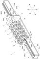
- FIG. 1 is a perspective view of a filament winding device 1.
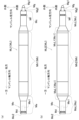
- FIG. FIG. 2(a) is a side view of the filament winding device 1.
- FIG. 2(b) is a side view of a core material (mandrel M) around which a plurality of fiber bundles are wound.
- FIG. 3 is a block diagram showing the electrical configuration of the filament winding device 1. As shown in FIG.
- the filament winding device 1 is configured to wind a plurality of fiber bundles around each of a plurality of mandrels M (mandrels for products of the present invention, see FIGS. 2(a) and 2(b)).
- the plurality of fiber bundles are not shown in FIGS. 1 to 3.
- "Wrapping the fiber bundle around the mandrel M” includes both winding the fiber bundle around the outer peripheral surface of the mandrel M and further winding the fiber bundle on top of the fiber bundle wound around the outer peripheral surface of the mandrel M.
- Each of the plurality of fiber bundles is made of, for example, a fiber material such as carbon fiber impregnated with a thermosetting or thermoplastic synthetic resin material.
- the mandrel M is, for example, a cylindrical or rod-shaped core material that extends in a predetermined mandrel axial direction.
- the mandrel M is made of a high-strength material such as metal.
- the resin impregnated into the plurality of fiber bundles is cured by going through a heat curing process such as firing or a cooling process.
- a fiber bundle-containing product is completed by pulling out the mandrel M from the fiber bundle-containing body containing a plurality of fiber bundles and a hardened resin.
- an integrated fiber bundle-containing body and mandrel M may be handled as a completed fiber bundle-containing product.
- the filament winding device 1 includes a pair of feeding units 2 (feeding units of the present invention), a hoop winding unit 3, and a plurality of (five in this embodiment) helical winding units. It includes a unit 4 and a control device 5. As will be described later, the filament winding device 1 uses a pair of feeding units 2 to move a plurality of mandrels M connected in the front-back direction from the front side to the rear side (from the upstream side to the downstream side in the feeding direction). It is configured. The filament winding device 1 also winds the plurality of fiber bundles supplied from the hoop winding unit 3 and the plurality of helical winding units 4 around each of the plurality of mandrels M being moved by the pair of feeding units 2. It is composed of
- the mandrel M extends long in a predetermined mandrel axial direction (left-right direction in the paper of FIG. 2(b)).
- the following description will proceed assuming that the mandrel M has a generally cylindrical or cylindrical shape. That is, it is assumed that the cross section of the mandrel M perpendicular to the mandrel axial direction is approximately circular. The center of the cross section is called the mandrel axis center.
- the radial direction of the mandrel M is called the mandrel radial direction.
- the mandrel M has, for example, a small diameter part Ma, a large diameter part Mb, and a small diameter part Mc. In the mandrel axial direction, the small diameter portion Ma, the large diameter portion Mb, and the small diameter portion Mc are arranged in this order.
- the shape of the mandrel M is not limited to a cylindrical shape or a cylindrical shape.
- the cross section of the mandrel M perpendicular to the mandrel axial direction may be polygonal. In this case, the center of gravity of the cross section may be referred to as the mandrel axis center. Alternatively, any other point on the cross section may be called the mandrel axis center.
- the small diameter portion Ma is a portion formed at one end of the mandrel M in the mandrel axial direction.
- the small diameter portion Ma has, for example, a generally cylindrical shape or a generally cylindrical shape.
- the small diameter portion Ma includes, for example, an inclined portion Ma1 having a substantially truncated conical shape and a columnar portion Ma2 having a substantially cylindrical shape.
- the inclined portion Ma1 is a portion adjacent to the large diameter portion Mb in the mandrel axial direction.
- the diameter of the inclined portion Ma1 becomes smaller as it is farther from the large diameter portion Mb in the mandrel axial direction.
- the cylindrical portion Ma2 is arranged on the opposite side of the large diameter portion Mb across the inclined portion Ma1 in the mandrel axial direction.
- the cylindrical portion Ma2 includes, for example, a chuck portion Md and a connecting portion Me.
- the chuck portion Md is a portion of the cylindrical portion Ma2 that is recessed inward in the radial direction of the mandrel.
- the chuck portion Md is configured to be held by a chuck mechanism 25A, which will be described later.
- the connecting portion Me is configured to be able to be connected to the small diameter portion Mc of another mandrel M.
- the connecting portion Me includes, for example, a recess Me1 into which a convex portion Mg1 described later can be inserted, and a plurality of positioning holes into which a plurality of positioning pins Mg2, which will be described later, can be inserted. Me2.
- the large diameter portion Mb is arranged on the other side of the small diameter portion Ma and on one side of the small diameter portion Mc in the mandrel axial direction. In other words, the large diameter portion Mb is arranged between the small diameter portion Ma and the small diameter portion Mc in the mandrel axial direction.
- the large diameter portion Mb has, for example, a substantially cylindrical shape or a substantially cylindrical shape. The shape of the large diameter portion Mb is not limited to this.
- the outer diameter of the large diameter portion Mb is larger than the outer diameter of the cylindrical portion Ma2 and the outer diameter of the cylindrical portion Mc2. The large diameter portion Mb extends over most of the mandrel M in the mandrel axial direction.
- the large diameter portion Mb has, for example, a pair of end portions Mb1 and a center portion Mb2.
- the pair of end portions Mb1 are arranged at both ends of the large diameter portion Mb in the mandrel axial direction.
- the center portion Mb2 is arranged between the pair of end portions Mb1 in the mandrel axial direction.
- the central portion Mb2 occupies most of the large diameter portion Mb in the mandrel axial direction.
- a fiber bundle-containing body including the fiber bundle wound around the central portion Mb2 is handled as a product (fiber bundle-containing product).
- the small diameter portion Mc is a portion formed at the other end of the mandrel M in the mandrel axial direction.
- the small diameter portion Mc has, for example, a generally cylindrical shape or a generally cylindrical shape.
- the small diameter portion Mc includes, for example, an inclined portion Mc1 having a substantially truncated cone shape and a cylindrical portion Mc2 having a substantially cylindrical shape.
- the inclined portion Mc1 is a portion adjacent to the large diameter portion Mb in the mandrel axial direction.
- the diameter of the inclined portion Mc1 becomes smaller as it is farther from the large diameter portion Mb in the mandrel axial direction.
- the cylindrical portion Mc2 is disposed on the opposite side of the large diameter portion Mb across the inclined portion Mc1 in the mandrel axial direction.
- the outer diameter of the cylindrical portion Mc2 is approximately equal to the outer diameter of the cylindrical portion Ma2.
- the cylindrical portion Mc2 includes a chuck portion Mf and a connecting portion Mg.
- the connecting portion Mg is configured to be connectable to the small diameter portion Ma of another mandrel M.
- the connecting portion Mg includes, for example, a convex portion Mg1 that protrudes to one side in the mandrel axial direction (the opposite side to the large diameter portion Mb), and a plurality of positioning pins Mg2 that similarly protrudes to one side in the mandrel axial direction.
- the protrusion Mg1 can be inserted into the recess Me1 of another mandrel M.
- Each of the plurality of positioning pins Mg2 can be inserted into any one of the plurality of positioning holes Me2.
- a plurality of mandrels M having the above structure can be arranged in the mandrel axial direction and connected to each other non-rotatably (that is, relatively non-rotatably). That is, the two mandrels M are connected through the connecting portion Me of one mandrel M and the connecting portion Mg of another mandrel M such that they cannot rotate relative to each other. In this way, two or more mandrels M can be connected in the mandrel axial direction and arranged so as to extend long along the mandrel axial direction.
- the pair of feeding units 2 are configured such that one or more mandrels M are non-rotatably mounted thereon.
- the pair of feeding units 2 are configured to be able to move one or more mandrels M from the front side (upstream side in the feeding direction) to the rear side (downstream side in the feeding direction).
- the feeding direction is approximately parallel to the mandrel axis direction of one or more mandrels M being moved by the pair of feeding units 2.
- the pair of feeding units 2 includes an upstream feeding unit 2A and a downstream feeding unit 2B.
- the upstream feeding unit 2A is arranged at the frontmost side of the filament winding device 1.
- the downstream feeding unit 2B is arranged at the rearmost side of the filament winding device 1.
- the pair of feeding units 2 are arranged so as to sandwich the hoop winding unit 3 and the helical winding unit 4 in the front-rear direction (that is, the feeding direction).
- the upstream feeding unit 2A includes a base portion 21A and a moving portion 22A.
- the base portion 21A is immovably installed on a floor surface 20 of a building (not shown).
- the base portion 21A includes a frame 23A, a rail 24A, and a chuck mechanism 25A.
- the frame 23A extends long in the front-rear direction.
- the rail 24A is configured to guide the moving section 22A in the front-back direction.
- the rail 24A is arranged on the upper surface of the frame 23A and extends long in the front-rear direction.
- the chuck mechanism 25A is arranged at the rear end of the frame 23A.
- the chuck mechanism 25A is configured to, for example, grip one chuck portion Md of a plurality of mandrels M, thereby holding the mandrel M so as to be immovable and unrotatable in the mandrel axial direction.
- the chuck mechanism 25A includes, for example, an air cylinder 26A (see FIG. 3) that is driven by supplying and discharging compressed air, and an upstream gripping member (not shown) that is driven by the air cylinder 26A.
- the supply and discharge of compressed air to and from the air cylinder 26A are controlled, for example, by the control device 5 opening and closing a solenoid valve (not shown) disposed in a compressed air flow path.
- the upstream gripping member is configured to be movable by the air cylinder 26A between a gripping position where it grips the chuck part Md and a release position where it releases gripping of the chuck part Md.
- the upstream gripping member may be driven by a motor (not shown) or the like instead of the air cylinder 26A.
- the moving part 22A is configured to be movable in the front and back direction with respect to the base part 21A.
- the moving section 22A includes a main body 27A and a traverse motor 28A.
- the main body 27A is connected to the mandrel M through one connecting portion Me of the plurality of mandrels M, and is configured to support the mandrel M in a non-rotatable manner.
- the main body 27A is configured to be guided in the front-back direction by the rails 24A.
- the main body 27A is driven to move back and forth by a traverse motor 28A.
- the traverse motor 28A is electrically connected to and controlled by the control device 5.
- the traverse motor 28A is configured to be able to move the main body 27A both forward and backward.
- the downstream feeding unit 2B includes a base portion 21B and a moving portion 22B.
- the downstream feeding unit 2B is configured to be approximately plane symmetrical to the upstream feeding unit 2A, with a predetermined virtual plane (not shown) orthogonal to the front-rear direction serving as a plane of symmetry. That is, the base portion 21B includes a frame 23B, a rail 24B, and a chuck mechanism 25B.
- the rail 24B extends long in the front-rear direction.
- the chuck mechanism 25B is arranged at the front end of the frame 23B.
- the chuck mechanism 25B is configured to, for example, grip one chuck portion Mf of a plurality of mandrels M, thereby holding the mandrel M so as to be immovable and unrotatable in the mandrel axial direction.
- the chuck mechanism 25B includes, for example, an air cylinder 26B (see FIG. 3) and a downstream gripping member (not shown) driven by the air cylinder 26B.
- the supply and discharge of compressed air to the air cylinder 26B are controlled by the control device 5 in the same way as the supply and discharge of compressed air to the air cylinder 26A.
- the downstream gripping member is configured to be movable by the air cylinder 26B between a gripping position where it grips the chuck part Mf and a release position where it releases gripping of the chuck part Mf.
- the downstream gripping member may be driven by a motor (not shown) or the like instead of the air cylinder 26B.
- the moving section 22B includes a main body 27B and a traverse motor 28B.
- the main body 27B is connected to the mandrel M through one connecting portion Mg of the plurality of mandrels M, and is configured to support the mandrel M in a non-rotatable manner.
- the main body 27B is configured to be guided in the front-back direction by the rails 24B.
- the main body 27B is driven to move in the front-back direction by a traverse motor 28B.
- the traverse motor 28B is electrically connected to and controlled by the control device 5.
- the traverse motor 28B is configured to be able to move the main body 27B both forward and backward.
- the hoop winding unit 3 is configured to perform hoop winding on the mandrel M.
- Hoop winding is a winding method in which the fiber bundle is wound in a direction generally perpendicular to the axial direction of the mandrel. As shown in FIG. 1, the hoop winding unit 3 is arranged, for example, immediately upstream of the downstream feeding unit 2B in the mandrel axial direction.
- the hoop winding unit 3 includes a main body 31 , a rotating member 32 , and a plurality of supply bobbins 33 .
- the main body portion 31 is fixed in position with respect to the floor surface 20.
- the main body portion 31 is configured to support the rotating member 32 rotatably around the axial center of the mandrel M.
- the rotating member 32 is, for example, a substantially disk-shaped member.
- a substantially circular passage hole 34 through which the mandrel M can pass is formed in the center of the rotating member 32.
- the rotating member 32 rotatably supports a plurality of supply bobbins 33 arranged outside the passage hole in the radial direction of the mandrel.
- a fiber bundle (not shown) is wound around each supply bobbin 33.
- the hoop winding unit 3 includes a rotary motor 35 (see FIG. 3) that is configured to rotate the rotary member 32.
- the rotary motor 35 is electrically connected to the control device 5 and is controlled by the control device 5.
- the control device 5 controls the feed unit 2 to move the mandrel M downstream in the feed direction, and controls the rotary motor 35 to rotate the rotating member 32.
- fiber bundles are pulled out from each supply bobbin 33 rotating around the mandrel M, and the plurality of fiber bundles are hoop-wound around the mandrel M.
- Each of the plurality of helical winding units 4 is configured to helically wind the mandrel M.
- Helical winding is a winding method in which the fiber bundle is wound in a direction that has a component in the mandrel axis direction, as compared to hoop winding.
- a winding method in which the fiber bundle is inclined at 45 degrees or less with respect to the mandrel axis direction is referred to as helical winding.
- the plurality of helical winding units 4 are arranged, for example, between the upstream feeding unit 2A and the hoop winding unit 3 in the feeding direction.
- the plurality of helical winding units 4 are arranged side by side in the front-back direction.
- FIG. 4(a) is a front view of the helical winding unit 4.
- FIG. 4(b) is an enlarged view of one supply bobbin and its peripheral configuration.
- FIG. 5(a) is a rear view of the helical winding unit 4.
- FIG. 5(b) is a side view of the helical winding unit 4.
- each helical winding unit 4 includes a base portion 41, a disk member 42, a plurality of supply bobbins 43, and a plurality of fiber bundles. It has a guide 44 and a mandrel support part 45.
- the position of the base portion 41 is fixed with respect to the floor surface 20 (see FIG. 2(a)).
- the base portion 41 is configured to support the disk member 42 rotatably around the axial center of the mandrel M.
- the disk member 42 is a substantially disk-shaped member configured to be rotatable with respect to the base portion 41 .
- the rotation axis direction of the disc member 42 is approximately parallel to the front-rear direction (that is, approximately parallel to the mandrel axial direction).
- a substantially circular passage hole 46 (see FIGS. 1 and 4(a)) through which the mandrel M can pass is formed in the center of the disk member 42.
- the disk member 42 is configured to support a plurality of supply bobbins 43 and a plurality of fiber bundle guides 44 that are arranged outside the passage hole 46 in the radial direction of the mandrel.
- the disk member 42 is rotationally driven around the axial center of the mandrel M by a disk rotating motor 47 (see FIGS. 3 and 5(b)) and a power transmission mechanism (not shown).
- a disc rotation motor 47 is provided in each helical winding unit 4.
- the disc rotation motor 47 is electrically connected to the control device 5 (see FIG. 3) and is controlled by the control device 5.
- the plurality of supply bobbins 43 are arranged side by side in the circumferential direction of the mandrel M (hereinafter referred to as the mandrel circumferential direction).
- a fiber bundle F (see FIGS. 4(a) and 4(b)) is wound around each supply bobbin 43.
- Each of the plurality of supply bobbins 43 is rotatably (rotatably) supported by, for example, a plate-shaped support member 48 (see FIGS. 4(b) and 5(b)).
- the support member 48 is fixed to the disk member 42. That is, the plurality of supply bobbins 43 are supported by the disk member 42 via the plurality of support members 48. Note that instead of the disk member 42 and the plurality of support members 48, one support member (not shown) that supports the plurality of supply bobbins 43 so as to be rotatable may be provided.
- the plurality of fiber bundle guides 44 are provided corresponding to the plurality of supply bobbins 43, respectively. Each of the plurality of fiber bundle guides 44 is attached to the disk member 42. The plurality of fiber bundle guides 44 are arranged inside the plurality of supply bobbins 43 in the mandrel radial direction. The plurality of fiber bundle guides 44 are arranged side by side in the circumferential direction of the mandrel. Each of the plurality of fiber bundle guides 44 is arranged so as to extend in a predetermined direction parallel to the radial direction of the mandrel. Each of the plurality of fiber bundle guides 44 is configured to guide the fiber bundle F unwound from the supply bobbin 43 inward in the radial direction of the mandrel.
- Each of the plurality of fiber bundle guides 44 is controlled, for example, by a guide turning motor 49 (see FIGS. 3 and 5(b)), which is a common driving source for the plurality of fiber bundle guides 44. It is configured to be driven to rotate with the direction of the rotation axis being the direction of the rotation axis.
- a guide rotation motor 49 is provided in each helical winding unit 4. The guide turning motor 49 is electrically connected to the control device 5 (see FIG. 3) and is controlled by the control device 5.
- a plurality of tension applying sections 50 are provided between the plurality of supply bobbins 43 and the plurality of fiber bundle guides 44 in the radial direction of the mandrel.
- the plurality of tension applying units 50 are configured to apply tension to each of the plurality of fiber bundles F (see FIGS. 4(a) and 4(b)).
- the plurality of tension applying sections 50 are provided corresponding to the plurality of supply bobbins 43 and the plurality of fiber bundle guides 44, respectively.
- Each of the plurality of tension applying sections 50 includes, for example, a first guide roller 51, a slack removing roller 52, and a second guide roller 53 (see FIG. 4(b)).
- the fiber bundle F pulled out from each supply bobbin 43 is wound around a first guide roller 51, a slack removing roller 52, and a second guide roller 53 provided in the corresponding tension applying section 50 in this order. Further, the fiber bundle F is guided inward in the mandrel radial direction by a corresponding fiber bundle guide 44.
- the mandrel support section 45 is configured to support the mandrel M being moved by the pair of feeding units 2.
- the mandrel support part 45 is arranged, for example, on the rear side of the disk member 42 (see FIGS. 2(a) and 5(b)).
- the mandrel support section 45 includes, for example, a support member 54 and a plurality of support rollers 55 to 58.
- the support member 54 is attached to, for example, the base portion 41 so as to be movable up and down.
- the support member 54 is driven to move in the vertical direction by a support vertical motor 54M (see FIGS. 3 and 6(a)) and a power transmission mechanism (not shown).
- the plurality of support rollers 55 to 58 are supported by the support member 54 so as to be rotatable and movable in the radial direction of the mandrel.
- Support rollers 55 and 56 are arranged below the path of mandrel M.
- Support rollers 55 and 56 are arranged adjacent to each other in the left-right direction.
- the support roller 57 is arranged, for example, on the diagonally upper left side of the passage of the mandrel M.
- the support roller 58 is arranged, for example, on the diagonally upper right side of the path of the mandrel M.
- the support rollers 55 to 58 are driven to move simultaneously in the mandrel radial direction by a support part opening/closing motor 59 (see FIGS.
- the support rollers 55 to 58 can be arranged at appropriate positions in the radial direction of the mandrel M in response to the increase in winding of the mandrel M due to the stacking of a plurality of fiber bundles F on the mandrel M.
- the support part opening/closing motor 59 is provided in each helical winding unit 4. The support part opening/closing motor 59 is electrically connected to the control device 5 (see FIG. 3) and is controlled by the control device 5.
- the support rollers 55 to 58 can be moved up and down all at once. This can prevent the following problems from occurring. That is, since the fiber bundle F wound around the mandrel M is soft, the fiber bundle F sandwiched between the mandrel M and the support rollers 55 and 56 is affected by the gravity acting on the mandrel M and the support rollers 55 and 56. There is a risk that it will be deformed (crushed) due to the reaction it receives. This may cause the mandrel M to bend under its own weight.
- the support rollers 55 to 58 can be moved slightly upward by the support vertical motor 54M, so that the fiber bundle F and the mandrel M can be kept at an appropriate height by the support rollers 55 and 56. I can support you. Therefore, deflection of the mandrel M can be suppressed.
- the control device 5 controls the pair of feeding units 2 to move the mandrel M downstream in the feeding direction, and controls the disk rotation motor 47 to rotate the disk member 42.
- the fiber bundles F are pulled out from each supply bobbin 43 rotating around the mandrel M, and the plurality of fiber bundles F are helically wound around the mandrel M.
- the control device 5 controls the guide turning motor 49 as necessary (according to the winding angle of the plurality of fiber bundles F around the mandrel M) to turn the plurality of fiber bundle guides 44.
- the control device 5 is, for example, a general computer device.
- the control device 5 includes an input section (not shown) that receives a predetermined input, an output section (not shown) that performs a predetermined output, and a storage section (not shown) that stores various information.
- the control device 5 is electrically connected to each component of the filament winding device 1.
- the control device 5 is configured to control each component of the filament winding device 1 according to a predetermined program.
- the filament winding device 1 is configured as follows. Further, in the filament winding device 1, a fiber bundle-containing product including a plurality of fiber bundles F is manufactured by a method described below.
- the filament winding device 1 has a plurality of jig mandrels MJ shown in FIGS. 6(a) and 6(b).
- FIG. 6A is a side view of the first jig mandrel MJ1, which is one of the plurality of jig mandrels MJ.
- FIG. 6(b) is a side view of a second jig mandrel MJ2 that is different from the first jig mandrel MJ1.
- the axial direction of the jig mandrel MJ will also be referred to as the mandrel axial direction, similar to the axial direction of the mandrel M.
- the plurality of jig mandrels MJ are jigs for fixing the tip of the fiber bundle F, etc. (details will be described later).
- Each of the plurality of jig mandrels MJ is a core material shorter than the mandrel M in the mandrel axial direction.
- the jig mandrel MJ has, for example, the above-mentioned small diameter portions Ma and Mc, and a large diameter portion Mh that is shorter in the mandrel axial direction than the large diameter portion Mb.
- the large diameter portion Mh is a portion to which the tip of the fiber bundle F and the like are fixed.
- the large diameter portion Mh has, for example, a substantially cylindrical shape or a substantially cylindrical shape.
- the shape of the large diameter portion Mh is not limited to this.
- the outer diameter of the large diameter portion Mh (large diameter portion Mh1) of the first jig mandrel MJ1 is approximately equal to the outer diameter of the mandrel M, for example.
- the outer diameter of the large diameter portion Mh (large diameter portion Mh2) of the second jig mandrel MJ2 is larger than the outer diameter of the first jig mandrel MJ1.
- the second jig mandrel MJ2 is thicker than the first jig mandrel MJ1.
- the outer diameter of the end of the inclined portion MaL1 on the large diameter portion Mh2 side in the mandrel axial direction is, for example, approximately equal to the outer diameter of the large diameter portion Mh2.
- the outer diameter of the end of the inclined portion McL1 on the large diameter portion Mh2 side in the mandrel axial direction is, for example, approximately equal to the outer diameter of the large diameter portion Mh2.
- FIG. 7(a) is a view of the connecting portion Me formed in the small diameter portion Ma viewed from one side of the small diameter portion Ma in the mandrel axial direction.
- FIG. 7(b) is a diagram of the connecting portion Mg formed in the small diameter portion Mc seen from the other side of the small diameter portion Mc in the mandrel axial direction.
- the connecting portion Me has, for example, eight positioning holes Me2.
- the eight positioning holes Me2 are arranged, for example, at approximately constant angular intervals in the circumferential direction of the mandrel. In other words, the eight positioning holes Me2 are arranged with the angular positions shifted by 45 degrees with the center of the mandrel axis mentioned above as the center point.
- the number and angular interval of the positioning holes Me2 described above are for convenience of explanation only. That is, the number and angular intervals of the positioning holes Me2 are not limited to those described above. Moreover, the angular interval between two positioning holes Me2 adjacent to each other does not necessarily have to be constant.
- the connecting portion Mg has, for example, two positioning pins Mg2.
- one of the two positioning pins Mg2 is called a positioning pin Mg2a, and the other is called a positioning pin Mg2b.
- the positioning pin Mg2a and the positioning pin Mg2b are arranged on opposite sides of the convex portion Mg1 when viewed from the mandrel axial direction.
- the positioning pin Mg2b is arranged at a position rotated 180 degrees from the positioning pin Mg2a, with the center of the mandrel shaft mentioned above as the center point.
- the moving section 22B of the downstream feeding unit 2B has a plurality of positioning holes into which two positioning pins Mg2 can be inserted. These positioning holes may be arranged with their angular positions shifted by 45 degrees, similarly to the eight positioning holes Me2. Furthermore, the moving section 22A of the upstream feeding unit 2A has a plurality of positioning pins that can be inserted into the eight positioning holes Me2. The number of these positioning pins may be two, for example, similar to the positioning pin Mg2 of each connecting portion Mg.
- the plurality of mandrels M and jig mandrels MJ can change the angle around the center of the mandrel axis in units of 45 degrees with respect to the pair of feed units 2 when viewed from the front and rear directions. .
- the plurality of fiber bundles supplied from the hoop winding unit 3 or the helical winding unit 4 are fixed (threaded) to the outer peripheral surface of the jig mandrel MJ as necessary. More details of threading will be described later.
- the jig mandrel MJ and the mandrel M are not attached to the pair of feeding units 2. Furthermore, the moving section 22A of the upstream feeding unit 2A and the moving section 22B of the downstream feeding unit 2B are arranged at appropriate positions in the front-rear direction.
- an operator grips the rear end of the first jig mandrel MJ1, which is the thinnest among the plurality of jig mandrels MJ, with the chuck mechanism 25A, and attaches the front end of the first jig mandrel MJ1 to the moving part 22A. (See FIG. 8(a)).
- the rear end of the first jig mandrel MJ1 is held unrotatably by the chuck mechanism 25A, and the front end is unrotatably supported by the moving part 22A.
- the first jig mandrel MJ1 is located at the upstream end in the feeding direction.
- the mandrel axial direction of the first jig mandrel MJ1 mounted on the moving part 22A is substantially parallel to the front-rear direction.
- the control device 5 controls the air cylinder 26A to release the grip of the first jig mandrel MJ1 by the chuck mechanism 25A.
- the control device 5 controls the traverse motor 28A to move the moving section 22A backward.
- the first jig mandrel MJ1 moves rearward (that is, downstream in the feeding direction).
- the moving distance of the moving part 22A and the mandrel M1 at this time in the front-rear direction is, for example, approximately the same distance as the length of the first jig mandrel MJ1 in the mandrel axial direction (see FIG. 8(b)).
- the control device 5 may temporarily stop the operation of the pair of feeding units 2 while the first jig mandrel MJ1 is being fed backward.
- the operator can perform work such as threading the first jig mandrel MJ1 (described later), for example.
- the control device 5 restarts the operation of the pair of feed units 2.
- control device 5 controls the air cylinder 26A to cause the chuck mechanism 25A to grip the first jig mandrel MJ1. Thereby, the first jig mandrel MJ1 is held unrotatably by the chuck mechanism 25A.
- control device 5 controls the traverse motor 28A to move the moving section 22A forward (see FIG. 8(c)). As a result, the moving section 22A is separated from the first jig mandrel MJ1.
- the operator connects the rear end of the mandrel M1, which is the mandrel M for the first product, to the first jig mandrel MJ1 in a relatively unrotatable manner, and rotates the front end of the mandrel M1 to the moving part 22A.
- the mandrel axial direction of the mandrel M1 is substantially parallel to the front-rear direction.
- the control device 5 controls the air cylinder 26A to release the grip of the first jig mandrel MJ1 by the chuck mechanism 25A.
- the control device 5 controls the traverse motor 28A to move the moving section 22A backward (see FIG. 9(b)).
- the control device 5 causes the chuck mechanism 25A to grip the mandrel M1, and moves the moving section 22A forward (see FIG. 9(c)). Thereby, the moving section 22A is separated from the mandrel M1.
- the operator connects the rear end of the mandrel M2, which is the mandrel M for the second product, to the mandrel M1 in a relatively unrotatable manner, and attaches the front end of the mandrel M2 to the moving part 22A in a non-rotatable manner.
- the control device 5 controls the air cylinder 26A to release the grip of the mandrel M1 by the chuck mechanism 25A.
- the control device 5 controls the traverse motor 28A to move the moving section 22A backward (see FIG. 10(b)).
- the first jig mandrel MJ1, mandrels M1 and M2 are sent downstream in the feeding direction.
- the rear end portion of the first jig mandrel MJ1 is non-rotatably attached to the moving portion 22B which is disposed at an appropriate position in the front-rear direction.
- the control device 5 may move the moving section 22B to the appropriate position after the rearward movement of the first jig mandrel MJ1 is completed.
- control device 5 controls the air cylinder 26B to cause the chuck mechanism 25B to grip the mandrel M1.
- the mandrel M1 is held unrotatably by the chuck mechanism 25B.
- the operator separates the first jig mandrel MJ1 from the moving part 22B and the mandrel M1 (see FIG. 10(c)).
- the control device 5 causes the chuck mechanism 25A to grip the mandrel M2, and moves the moving parts 22A and 22B forward (see FIG. 11(a)).
- the moving section 22A is separated from the mandrel M2.
- the mandrel M1 is non-rotatably attached to the moving part 22B.
- the operator connects the rear end of the mandrel M3, which is the mandrel M for the third product, to the mandrel M2 in a relatively unrotatable manner, and attaches the front end of the mandrel M3 to the moving part 22A in a non-rotatable manner. (See FIG. 11(b)).
- control device 5 releases the grip of the mandrel M1 by the chuck mechanism 25A, and moves the moving section 22A backward (see FIG. 11(c)).
- the mandrels M1 to M3 are sent downstream in the feeding direction.
- Mandrel M1 reaches the downstream end in the feeding direction.
- the step of arranging the mandrels M1 to M3 in the mandrel axial direction and sequentially connecting them so that they cannot rotate relative to each other on the upstream side of the jig mandrel MJ in the feeding direction corresponds to the connecting step of the present invention.
- the process of feeding all of the mandrels M1 to M3 (that is, one mandrel group) once from the upstream end to the downstream end in the feeding direction is hereinafter referred to as a unit feeding process.
- the control device 5 causes the chuck mechanism 25B to grip the mandrel M2, thereby making it possible to separate the mandrel M1 from the moving portion 22B and the mandrel M2 (not shown).
- the operator can carry the mandrel M1 and return it to the front.
- the operator can place the mandrel M1 again at the upstream end of the feeding process, if necessary.
- the operator may place the mandrel M1 immediately upstream in the feeding process of the mandrel M3.
- the operator may place the jig mandrel MJ between the mandrel M1 and the mandrel M3 as necessary. In this way, the unit feeding process described above can be repeated many times.
- the mandrels M1 to M3 can be carried toward the hoop winding unit 3 and the plurality of helical winding units 4 many times. Thereby, multiple layers of fiber bundles can be wound around the mandrels M1, M2, and M3. By adjusting the moving speed of the moving parts 22A and 22B, the loading speed can be adjusted. Although the procedure for moving the mandrels M1 to M3 has been described here, it is also possible to sequentially move four or more mandrels M in the feeding direction using the same procedure.
- the operator grips the rear end of the first jig mandrel MJ1 with the chuck mechanism 25A, and attaches the front end of the first jig mandrel MJ1 to the moving part 22A (FIG. 8(a)). reference). Thereafter, the operator operates the control device 5 to release the grip of the first jig mandrel MJ1 by the chuck mechanism 25A, and moves the first jig mandrel MJ1 backward.
- the control device 5 controls the control device 5 so that, in the front-rear direction, the rear end of the large diameter portion Mh1 of the first jig mandrel MJ1 is located at approximately the same position as the plurality of fiber bundle guides 44 of the helical winding unit 4a disposed at the frontmost side.
- the moving unit 22A is moved until the target is reached.
- the control device 5 stops the moving section 22A.
- the first jig mandrel MJ1 moves and stops at a position where the thread can be threaded (see FIG. 12(a)). Note that the position where the first jig mandrel MJ1 stops moving is not limited to this.
- the operator pulls out the fiber bundle F from each of the plurality of supply bobbins 43 of the helical winding unit 4a. Further, the operator passes each fiber bundle F through the corresponding tension applying section 50 and fiber bundle guide 44, and guides the tip end of each fiber bundle F inward in the radial direction of the mandrel. That is, the operator positions the tip end of each of the plurality of fiber bundles F near the first jig mandrel MJ1. Next, the operator uses a fixing device such as a tape T (preferably a curing tape) to attach the tip of each of the plurality of fiber bundles F to the outer peripheral surface of the large diameter portion Mh1 of the first jig mandrel MJ1. (See Figure 12(a)).
- a fixing device such as a tape T (preferably a curing tape)
- the plurality of tip portions are fixed to the first jig mandrel MJ1.
- threading on the first jig mandrel MJ1 in the helical winding unit 4a is completed.
- the operator attaches the tip end portions of each of the plurality of fiber bundles F to the outer peripheral surface of the large diameter portion Mh1 at approximately equal angular intervals (angular intervals around the center of the mandrel axis).
- the operator operates the control device 5 to move the first jig mandrel MJ1 backward.
- the control device 5 moves the moving part 22A backward at an appropriate speed, and controls the disk rotation motor 47 of the helical winding unit 4a to rotate the disk member 42 in a predetermined direction at a predetermined rotation speed.
- the tip end of each of the plurality of fiber bundles is pulled by the first jig mandrel MJ1, and the fiber bundle F is pulled out from each of the plurality of supply bobbins 43 of the helical winding unit 4a.
- the plurality of fiber bundles F are wound around the outer peripheral surface of the first jig mandrel MJ1 at a predetermined winding angle (see FIG.
- the control device 5 moves the moving section 22A until the rear end of the large diameter section Mh1 reaches approximately the same position as the plurality of fiber bundle guides 44 of the helical winding unit 4a.
- the operator threads the first jig mandrel MJ1 in the helical winding unit 4b using the same method as described above (see FIG. 12(b)).
- the operator operates the control device 5 to move the first jig mandrel MJ1 backward, for example, after mounting the mandrel M1 on the first jig mandrel MJ1 and the moving section 22A.
- the control device 5 moves the moving part 22A backward at an appropriate speed, and also controls the disk rotation motors 47 of each of the helical winding units 4a and 4b to rotate each disk member 42 in a predetermined direction at a predetermined rotation speed. Rotate with .
- the plurality of fiber bundles F supplied from the helical winding unit 4b are wound around the first jig mandrel MJ1 at a predetermined winding angle (see FIG. 12(c)).
- the plurality of fiber bundles F supplied from the helical winding unit 4a After being wound around the first jig mandrel MJ1, the plurality of fiber bundles F supplied from the helical winding unit 4a begin to be wound around the mandrel M1 (see FIG. 12(c)). Therefore, there is no need to thread the mandrel M1. This prevents the tip of the fiber bundle F from getting mixed into the mandrel M1. Note that the winding angle of the fiber bundle F around the mandrel M1 before being thickened is approximately equal to the winding angle of the fiber bundle F around the first jig mandrel MJ1.
- the control device 5 moves the moving section 22A until the rear end of the large diameter section Mh1 reaches approximately the same position as the plurality of fiber bundle guides 44 of the helical winding unit 4c. Further, the operator threads the first jig mandrel MJ1 in the helical winding unit 4c using the same method as described above (see FIG. 12(c)). As described above, as an example, threading is performed on the first jig mandrel MJ1.
- FIG. 13 is a flowchart showing a procedure for winding a plurality of fiber bundles around a plurality of mandrels M.
- FIGS. 14(a) and 14(b) are explanatory diagrams showing changes in the winding angle of the fiber bundle F.
- the hoop winding step is performed, for example, by sequentially hoop winding the plurality of mandrels M while sequentially feeding the plurality of mandrels M to the downstream side in the feeding direction when the plurality of helical winding units 4 are not used. Ru.
- the operator may perform threading on the jig mandrel MJ similar to the threading described above.
- the process of sequentially performing helical winding on a plurality of mandrels M by a plurality of helical winding units 4 is hereinafter referred to as a helical winding process.
- the number of helical winding units 4 used in the helical winding process is appropriately adjusted according to changes in the winding angle and/or increase in the diameter of the fiber bundle-containing product (rolling thickness).
- the number of helical winding units 4 used is adjusted in order to make the coverage of the fiber bundle F on the mandrel M approximately equal (for example, about 100 percent) per unit feeding process.
- the number of helical winding units 4 used is constant (not changed).
- a plurality of fiber bundles F are supplied by three helical winding units 4 among the five helical winding units 4.
- the depletion of the fiber bundle F included in the supply bobbin 43 and the associated replacement of the supply bobbin 43 are not considered.
- the operator attaches the first jig mandrel MJ1 to the upstream feeding unit 2A as described above, and then performs a predetermined operation on the control device 5.
- the control device 5 controls the pair of feeding units 2 to feed the first jig mandrel MJ1 downstream in the feeding direction (jig feeding process).
- the control device 5 stops the movement of the first jig mandrel MJ1 at the timing when the first jig mandrel MJ1 reaches the vicinity of the helical winding unit 4 that requires threading.
- the operator pulls out a plurality of fiber bundles F from each of the plurality of helical winding units 4 to be used at an appropriate timing, and sequentially threads them onto the first jig mandrel MJ1 (threading process. S101. Fig. 12(a) ) to (c)).
- the operator attaches and detaches the mandrel M (or jig mandrel MJ) to and from the pair of feeding units 2 and operates the control device 5 as necessary.
- the control device 5 controls the pair of feeding units 2 and the helical winding unit 4 according to the operation of the control device 5 by the operator, and winds the fiber bundle F around a plurality of mandrels M belonging to a predetermined mandrel group.
- the operator lines up the plurality of mandrels M in the mandrel axial direction and sequentially connects them so that they cannot rotate relative to each other (connection process).
- the operator sequentially removes the jig mandrel MJ or mandrel M sent to the downstream end in the feeding direction from the downstream feeding unit 2B.
- the operator cuts each fiber bundle F wound around the jig mandrel MJ using a cutter (not shown).
- the operator connects the end of each fiber bundle F extending downstream from the rear end of the mandrel M disposed immediately upstream of the jig mandrel MJ in the feeding direction to the small diameter portion Ma of the mandrel M. and the small diameter portion Mc with a tape T.
- the one small diameter portion is a portion of the mandrel M that is disposed on the downstream side in the feeding direction. Furthermore, before removing the mandrel M from the downstream feeding unit 2B, the operator cuts each fiber bundle F wound around the other of the small diameter portions Ma and Mc of the mandrel M using a cutter not shown. The other small diameter portion is a portion of the mandrel M that is disposed on the upstream side in the feeding direction. Also, at this time, the operator fixes the end of each fiber bundle F extending upstream from the front end of the mandrel M to the other small diameter part with tape T.
- the operator judges whether or not to continue winding the fiber bundle F around the mandrel M, for example, based on a process chart (not shown) that describes the manufacturing procedure for a product containing fiber bundles. (S103).
- the timing of the determination is, for example, when the mandrel M around which the fiber bundle F is wound at the end of each unit feeding process is attached to the upstream feeding unit 2A. If it is determined that the winding of the fiber bundle F around the mandrel M is not to be continued (S103: No), for example, after the winding of the fiber bundle F around the last mandrel M is completed in the last unit feeding process, the fiber bundle containing Manufacturing of the product ends.
- the operator determines to continue winding the fiber bundle around the mandrel M (S103: Yes)
- the operator further makes a determination as described below.
- the operator determines whether or not to change the wrapping angle in the next unit feeding process (S104). If the winding angle is not to be changed (S104: No), the operator returns to S102 and starts the next unit feeding process. At this time, it is not necessary to thread the mandrels M sequentially mounted on the upstream feeding unit 2A.
- the helical winding process before changing the winding angle corresponds to the first helical winding process of the present invention.
- the winding angle in the first helical winding step corresponds to the first winding angle of the present invention.
- the helical winding step after changing the winding angle corresponds to the second helical winding step of the present invention.
- the winding angle in the second helical winding step corresponds to the second winding angle of the present invention.
- the helical winding process includes a first helical winding process and a second helical winding process.
- the winding angle takes into consideration not only the magnitude of the inclination angle of the fiber bundle F with respect to the mandrel M, etc., but also whether the fiber bundle F is wound clockwise or counterclockwise when viewed from the front and back directions. .
- the winding angle is one of ⁇ 45 degrees (for example, +45 degrees).
- the winding angle is defined as the other of ⁇ 45 degrees (for example, ⁇ 45 degrees). Changes in the magnitude of the wrapping angle (for example, from 45 degrees to 5 degrees) and changes in the sign of the wrapping angle (for example, from +45 degrees to -45 degrees) are included in changes in the wrapping angle. .
- the operator attaches an appropriate jig mandrel MJ (details will be described later) to the upstream feeding unit 2A, and then attaches the jig mandrel MJ to the most upstream position in the feeding direction. It is connected to the mandrel M in a relatively non-rotatable manner.
- the most upstream mandrel M is the mandrel M on which the plurality of fiber bundles F are wound at the end of the first helical winding step.
- the mandrel M corresponds to the first mandrel of the present invention.
- the operator sends the jig mandrel MJ to the helical winding unit 4 (helical winding unit 4a in FIG. 14(a)) that is supplying the fiber bundle F whose winding angle needs to be changed. Operate the control device 5.
- the process of feeding the jig mandrel MJ in this manner corresponds to the winding angle changing jig feeding process of the present invention.
- the operator wraps the intermediate portion of each of the plurality of fiber bundles supplied from the helical winding unit 4a onto the large diameter portion Mh of the jig mandrel MJ using tape T (see tape Tc in FIG. 14(a)). Fix it (winding angle change fixing process).
- the control device 5 controls the pair of feeding units 2 while rotating the disk member 42 of the helical winding unit 4a at a rotation speed different from that of the disk member 42 of the other helical winding units 4.
- the rotation speed here is a concept that includes not only the speed of rotation but also the direction of rotation.
- the winding angle on the upstream side of the tape Tc in the feeding direction is different from the winding angle on the downstream side of the tape Tc in the feeding direction (see FIG. 14(b)).
- the winding angles of all the fiber bundles F on the jig mandrel MJ are changed.
- the operator connects one of the plurality of mandrels M to the jig mandrel MJ in a relatively non-rotatable manner at an appropriate timing (winding angle changing connection step).
- the one mandrel M is the mandrel M on which the plurality of fiber bundles F are wound at the beginning of the second helical winding step.
- the one mandrel M corresponds to the second mandrel of the present invention. Thereafter, the operator causes the filament winding device 1 to perform the next unit feeding process. In this way, the unit feeding process is repeated while the winding angle of the fiber bundle F is changed.
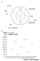
- FIG. 15(a) is an explanatory diagram showing a change in the angle of the mandrel M around the center of the mandrel axis.
- FIG. 15(b) is a graph for explaining the change in angle.
- the horizontal axis of the graph indicates the total number of unit feeding steps.
- the vertical axis of the graph indicates the angle of the mandrel M around the center of the mandrel axis.
- a plurality of mandrels M are held side by side in a substantially horizontal direction, and are supported from below by the mandrel support portion 45.
- the fiber bundle F which is generally softer than the mandrel M, is pushed from below by the mandrel support portion 45, the fiber bundle F wound around the mandrel M is likely to be distorted. Therefore, the shape of the product may be distorted. Therefore, in order to suppress the collapse of the shape of the product, the following method is preferably implemented.
- the plurality of mandrels M can change the angle around the mandrel axis center in 45 degree increments with respect to the pair of feeding units 2 when viewed from the front and rear directions (see FIG. 15(a)). . Therefore, the operator changes the angles of the plurality of mandrels M around the center of the mandrel axis each time the unit feeding process is executed a predetermined first number of times.
- the first number of times is a predetermined number of times of 1 or more.
- the angle around the center of the mandrel axis will be defined as follows. As shown by the solid line in FIG.
- the angle around the center of the mandrel axis is 0. It is defined as degree. Further, for example, when the positioning pin Mg2a is tilted 45 degrees clockwise from directly above the convex portion Mg1 when viewed from the front side, the angle around the center of the mandrel axis is defined as 45 degrees. For example, as shown by the broken line in FIG. 15(a), the angular position of the positioning pin Mg2 around the center of the mandrel axis can be changed in units of 45 degrees.
- the range of angles around the center of the mandrel axis is defined as, for example, 0 degrees or more and less than 360 degrees. In this way, the angle of the mandrel M around the center of the mandrel axis can be changed in 45 degree increments from 0 degrees to 360 degrees (in this embodiment, strictly speaking, up to 315 degrees).
- the predetermined angle When the first number of times is, for example, two times, as shown in the graph of FIG. is changed by a predetermined angle other than a multiple of 360 degrees.
- the predetermined angle will also be referred to as a "change angle.”
- the changing angle it is preferable that the changing angle be unified among the plurality of mandrels M in one unit feeding process.
- the predetermined angle (change angle) is 135 degrees.
- the angle of the plurality of mandrels M around the mandrel axis center is changed from 270 degrees to 45 degrees. This 45 degrees is an angle calculated by subtracting 360 degrees from 405 degrees obtained by adding 135 degrees to 270 degrees.
- the position where the fiber bundle-containing product is pushed from below by the mandrel support part 45 can be changed in the mandrel circumferential direction. That is, the fiber bundles F stacked at the same position in the mandrel circumferential direction of each mandrel M can be prevented from being repeatedly pushed from below by the mandrel support portion 45.
- the fiber bundle-containing product There is a possibility that the winding angle of the fiber bundle F around the product deviates from the target angle.
- the reason for this is as follows. If the diameter of the jig mandrel MJ and the diameter of the fiber bundle-containing product are different, the relative peripheral speed of the plurality of fiber bundle guides 44 of the helical winding unit 4 to the jig mandrel MJ and the relative relative to the fiber bundle-containing product The circumferential speeds are different from each other. Due to this, there is a possibility that the winding angle of the fiber bundle F around the fiber bundle-containing product is significantly different from the winding angle of the fiber bundle F around the first jig mandrel MJ1.
- the operator preferably attaches the second jig mandrel MJ2 to the upstream feeding unit 2A. do.
- the difference between the diameter of the second jig mandrel MJ2 and the diameter of the fiber bundle-containing product is smaller than the difference between the diameter of the first jig mandrel MJ1 and the diameter of the fiber bundle-containing product.
- the plurality of mandrels M are sequentially connected in a relatively non-rotatable manner on the upstream side of the jig mandrel MJ in the feeding direction. and are sequentially sent to the downstream side in the feeding direction.
- Helical winding is performed on the plurality of mandrels M that are sequentially fed in this manner.
- a plurality of fiber bundles F are wound around a plurality of mandrels M to avoid the tips of the fiber bundles F from getting mixed into the product formed by winding the plurality of fiber bundles F around a plurality of mandrels M. Can be wrapped. Therefore, in the filament winding device 1 that helically winds the mandrel M while continuously feeding the mandrel M, it is possible to avoid contamination of the product with foreign matter.
- the method for manufacturing a fiber bundle-containing product includes a winding angle changing jig feeding step, a winding angle changing fixing step, and a winding angle changing connecting step.
- the angle around the axis of the plurality of mandrels M in the next unit feeding process is a multiple of 360 degrees.
- a predetermined angle other than that is changed.
- the second jig mandrel MJ2 which is thicker than the first jig mandrel MJ1
- the winding angle of the fiber bundle F around the second jig mandrel MJ2 and the winding angle of the fiber bundle F around the thickly wound fiber bundle-containing product can be easily made to substantially match. Therefore, the wrapping angle of the fiber bundle F around the fiber bundle-containing product can be made as close to the target angle as possible.
- the angle of the plurality of mandrels M around the mandrel axis center is changed by 135 degrees.
- the above-mentioned change angle may be other than 135 degrees (for example, 45 degrees, 90 degrees, 180 degrees, etc.).
- the angular interval of the plurality of positioning holes Me2 around the center of the mandrel axis may be other than 45 degrees.
- such work of changing the angle around the center of the mandrel axis may not be performed.
- the jig mandrel MJ has the small diameter portions Ma and Mc like the mandrel M. However, it is not limited to this.
- the jig mandrel MJ may have a small diameter portion (not shown) that is different in shape from the small diameter portions Ma and Mc of the mandrel M. Furthermore, the shapes of the small diameter portions Ma and Mc of the mandrel M are not limited to those described above.
- the filament winding device 1 is provided with the first jig mandrel MJ1 and the second jig mandrel MJ2 as the jig mandrel MJ.
- the number of jig mandrels MJ is not limited to this.
- one or more jig mandrels that are thicker than the second jig mandrel MJ2 may be provided.
- the filament winding device 1 may include only the first jig mandrel MJ1 as the jig mandrel MJ.
- the middle portion of each of the plurality of fiber bundles F is fixed to the jig mandrel MJ. did.
- the plurality of fiber bundles F supplied from the helical winding unit 4 may be cut every time the unit feeding process is completed once.
- the tips of each of the plurality of fiber bundles F are fixed to the jig mandrel MJ, even if the winding angle is changed. good.
- production efficiency decreases.
- the mandrel M and the jig mandrel MJ have small diameter portions Ma and Mc.
- the mandrel M may have both end portions (not shown) having substantially the same diameter as the large diameter portion Mb instead of the small diameter portions Ma and Mc.
- the jig mandrel MJ may have both end portions (not shown) having substantially the same diameter as the large diameter portion Mh instead of the small diameter portions Ma and Mc.
- the disk member 42 and the fiber bundle guide 44 are configured to be integrally rotatable around the mandrel axis. However, it is not limited to this. The disk member 42 and the fiber bundle guide 44 do not need to be configured to be rotatable around the mandrel axis.
- the pair of feeding units 2 may be configured to move the plurality of mandrels M in the feeding direction while rotating them around the center of the mandrel axis.
- the winding angles of the fiber bundles F around the plurality of mandrels M cannot be made different between the plurality of helical winding units 4 that simultaneously supply the plurality of fiber bundles F.
- the filament winding device 1 was provided with five helical winding units 4.
- the number of helical winding units 4 is not limited to this.
- the filament winding device 1 may include a plurality of helical winding units 4, less than five or more than five. Further, the filament winding device 1 may include a plurality of hoop winding units 3.
- the positional relationship between the hoop winding unit 3 and the plurality of helical winding units 4 in the mandrel axial direction is not limited to that described above.
- the hoop winding unit 3 may be arranged in front of the plurality of helical winding units 4.
- the fiber bundle before being wound around the mandrel M is impregnated with resin.
- the fiber bundle wound around the mandrel M may be impregnated with a resin.
- Mandrel support section F Fiber bundle M Mandrel (product mandrel) MJ Jig mandrel MJ1 1st jig mandrel MJ2 2nd jig mandrel
Landscapes
- Engineering & Computer Science (AREA)
- Mechanical Engineering (AREA)
- Chemical & Material Sciences (AREA)
- Composite Materials (AREA)
- Textile Engineering (AREA)
- Moulding By Coating Moulds (AREA)
Priority Applications (5)
| Application Number | Priority Date | Filing Date | Title |
|---|---|---|---|
| EP23839416.7A EP4556206A1 (en) | 2022-07-14 | 2023-06-21 | Method for producing fiber-bundle-containing product, and filament winding apparatus |
| JP2024533603A JPWO2024014241A1 (https=) | 2022-07-14 | 2023-06-21 | |
| US18/992,698 US20260021628A1 (en) | 2022-07-14 | 2023-06-21 | Method for manufacturing fiber bundle-containing product, and filament winding apparatus |
| KR1020257001330A KR20250023543A (ko) | 2022-07-14 | 2023-06-21 | 섬유속 함유 제품의 제조 방법, 및 필라멘트 와인딩 장치 |
| CN202380047576.0A CN119365325A (zh) | 2022-07-14 | 2023-06-21 | 含纤维束产品的制造方法以及长纤维卷绕装置 |
Applications Claiming Priority (2)
| Application Number | Priority Date | Filing Date | Title |
|---|---|---|---|
| JP2022-113038 | 2022-07-14 | ||
| JP2022113038 | 2022-07-14 |
Publications (1)
| Publication Number | Publication Date |
|---|---|
| WO2024014241A1 true WO2024014241A1 (ja) | 2024-01-18 |
Family
ID=89536653
Family Applications (1)
| Application Number | Title | Priority Date | Filing Date |
|---|---|---|---|
| PCT/JP2023/022905 Ceased WO2024014241A1 (ja) | 2022-07-14 | 2023-06-21 | 繊維束含有製品の製造方法、及びフィラメントワインディング装置 |
Country Status (6)
| Country | Link |
|---|---|
| US (1) | US20260021628A1 (https=) |
| EP (1) | EP4556206A1 (https=) |
| JP (1) | JPWO2024014241A1 (https=) |
| KR (1) | KR20250023543A (https=) |
| CN (1) | CN119365325A (https=) |
| WO (1) | WO2024014241A1 (https=) |
Citations (13)
| Publication number | Priority date | Publication date | Assignee | Title |
|---|---|---|---|---|
| DE3344989A1 (de) * | 1983-12-13 | 1985-06-20 | Messerschmitt-Bölkow-Blohm GmbH, 8012 Ottobrunn | Vorrichtung zur fixierung des faserstrangendes bei wickelmaschinen |
| DE3735778A1 (de) * | 1987-10-22 | 1989-05-03 | Baer Maschf Josef | Faserwickelmaschine zur herstellung von verbundstoffkoerpern aus kunststoff und fasern |
| JPH0696268B2 (ja) * | 1989-01-24 | 1994-11-30 | 積水化学工業株式会社 | 樹脂複合管の製造方法及びそれに用いられる連結部材 |
| JPH1158540A (ja) * | 1997-08-20 | 1999-03-02 | Murata Mach Ltd | ブレイダーによる中空容器作成システム及び耐圧容器 |
| JP2004148777A (ja) * | 2002-11-01 | 2004-05-27 | Toyota Industries Corp | 圧力容器の製造方法及び繊維束配列装置 |
| JP2009039951A (ja) * | 2007-08-09 | 2009-02-26 | Murata Mach Ltd | フィラメントワインディング自動化システム |
| JP2009051014A (ja) * | 2007-08-23 | 2009-03-12 | Murata Mach Ltd | フィラメントワインディング自動化システム |
| JP2009066818A (ja) * | 2007-09-11 | 2009-04-02 | Murata Mach Ltd | マンドレルの搬送装置 |
| JP2009066883A (ja) * | 2007-09-12 | 2009-04-02 | Murata Mach Ltd | フィラメントワインディング装置 |
| JP2014117913A (ja) | 2012-12-18 | 2014-06-30 | Murata Mach Ltd | パイプ製造装置 |
| JP2015085641A (ja) * | 2013-10-31 | 2015-05-07 | 村田機械株式会社 | フィラメントワインディング装置 |
| JP2016172402A (ja) * | 2015-03-17 | 2016-09-29 | 村田機械株式会社 | フィラメントワインディング装置 |
| JP2020082375A (ja) | 2018-11-15 | 2020-06-04 | 村田機械株式会社 | フィラメントワインディング装置 |
Family Cites Families (1)
| Publication number | Priority date | Publication date | Assignee | Title |
|---|---|---|---|---|
| CA1212529A (en) * | 1982-07-08 | 1986-10-14 | Dee R. Gill | Manufacture of filamentary composites |
-
2023
- 2023-06-21 CN CN202380047576.0A patent/CN119365325A/zh active Pending
- 2023-06-21 WO PCT/JP2023/022905 patent/WO2024014241A1/ja not_active Ceased
- 2023-06-21 US US18/992,698 patent/US20260021628A1/en active Pending
- 2023-06-21 JP JP2024533603A patent/JPWO2024014241A1/ja active Pending
- 2023-06-21 EP EP23839416.7A patent/EP4556206A1/en active Pending
- 2023-06-21 KR KR1020257001330A patent/KR20250023543A/ko active Pending
Patent Citations (13)
| Publication number | Priority date | Publication date | Assignee | Title |
|---|---|---|---|---|
| DE3344989A1 (de) * | 1983-12-13 | 1985-06-20 | Messerschmitt-Bölkow-Blohm GmbH, 8012 Ottobrunn | Vorrichtung zur fixierung des faserstrangendes bei wickelmaschinen |
| DE3735778A1 (de) * | 1987-10-22 | 1989-05-03 | Baer Maschf Josef | Faserwickelmaschine zur herstellung von verbundstoffkoerpern aus kunststoff und fasern |
| JPH0696268B2 (ja) * | 1989-01-24 | 1994-11-30 | 積水化学工業株式会社 | 樹脂複合管の製造方法及びそれに用いられる連結部材 |
| JPH1158540A (ja) * | 1997-08-20 | 1999-03-02 | Murata Mach Ltd | ブレイダーによる中空容器作成システム及び耐圧容器 |
| JP2004148777A (ja) * | 2002-11-01 | 2004-05-27 | Toyota Industries Corp | 圧力容器の製造方法及び繊維束配列装置 |
| JP2009039951A (ja) * | 2007-08-09 | 2009-02-26 | Murata Mach Ltd | フィラメントワインディング自動化システム |
| JP2009051014A (ja) * | 2007-08-23 | 2009-03-12 | Murata Mach Ltd | フィラメントワインディング自動化システム |
| JP2009066818A (ja) * | 2007-09-11 | 2009-04-02 | Murata Mach Ltd | マンドレルの搬送装置 |
| JP2009066883A (ja) * | 2007-09-12 | 2009-04-02 | Murata Mach Ltd | フィラメントワインディング装置 |
| JP2014117913A (ja) | 2012-12-18 | 2014-06-30 | Murata Mach Ltd | パイプ製造装置 |
| JP2015085641A (ja) * | 2013-10-31 | 2015-05-07 | 村田機械株式会社 | フィラメントワインディング装置 |
| JP2016172402A (ja) * | 2015-03-17 | 2016-09-29 | 村田機械株式会社 | フィラメントワインディング装置 |
| JP2020082375A (ja) | 2018-11-15 | 2020-06-04 | 村田機械株式会社 | フィラメントワインディング装置 |
Also Published As
| Publication number | Publication date |
|---|---|
| KR20250023543A (ko) | 2025-02-18 |
| JPWO2024014241A1 (https=) | 2024-01-18 |
| CN119365325A (zh) | 2025-01-24 |
| EP4556206A1 (en) | 2025-05-21 |
| US20260021628A1 (en) | 2026-01-22 |
Similar Documents
| Publication | Publication Date | Title |
|---|---|---|
| US7905442B2 (en) | Filament winding apparatus | |
| US8105454B2 (en) | Filament winding apparatus and method thereof | |
| EP2255950B1 (en) | Method for operating a filament winding apparatus | |
| US7282107B2 (en) | Multiple head automated composite laminating machine for the fabrication of large barrel section components | |
| JP5278662B2 (ja) | フィラメントワインディング装置 | |
| US10926315B2 (en) | Systems and processes for feeding longitudinal wires or rods to mesh producing machines | |
| JP6460865B2 (ja) | コイル巻線装置及びコイル製造方法 | |
| US7665290B2 (en) | Twister, method for producing twisted wire, ply, and pneumatic tire | |
| JP6825428B2 (ja) | フィラメントワインディング装置 | |
| WO2010026753A1 (ja) | ストリップ材のスパイラル巻回装置 | |
| JP5796724B2 (ja) | フィラメントワインディング装置 | |
| WO2024014241A1 (ja) | 繊維束含有製品の製造方法、及びフィラメントワインディング装置 | |
| CN113785371B (zh) | 绕线机和绕线方法 | |
| JP5029134B2 (ja) | 繊維束配列装置 | |
| JP2006218777A (ja) | 2重円筒によるコードで補強されたゴムシートの製造装置及び製造方法 | |
| JP2017164873A (ja) | ワイヤ加工システム及びワイヤ加工方法 | |
| JP2024003434A (ja) | フィラメントワインディング装置 | |
| JP4492464B2 (ja) | 繊維束配列装置 | |
| JPWO2024014241A5 (https=) | ||
| WO2019171926A1 (ja) | 巻線装置及びこれを用いた製造設備並びに巻線方法及び完成品の製造方法 | |
| JP7732966B2 (ja) | フィラメントワインディング装置及びフィラメントワインディング方法 | |
| JP2024037297A (ja) | 線材繰出し装置及びそれを備えた巻線装置 | |
| JPH08246304A (ja) | ブレイダー及び組成体 | |
| KR20200025460A (ko) | 와이어 핸들러 | |
| US20240092039A1 (en) | Winding Apparatus for Producing Fiber-Reinforced Components |
Legal Events
| Date | Code | Title | Description |
|---|---|---|---|
| 121 | Ep: the epo has been informed by wipo that ep was designated in this application |
Ref document number: 23839416 Country of ref document: EP Kind code of ref document: A1 |
|
| WWE | Wipo information: entry into national phase |
Ref document number: 2024533603 Country of ref document: JP |
|
| WWE | Wipo information: entry into national phase |
Ref document number: 202380047576.0 Country of ref document: CN |
|
| WWE | Wipo information: entry into national phase |
Ref document number: 18992698 Country of ref document: US |
|
| ENP | Entry into the national phase |
Ref document number: 20257001330 Country of ref document: KR Kind code of ref document: A |
|
| WWE | Wipo information: entry into national phase |
Ref document number: 1020257001330 Country of ref document: KR |
|
| WWP | Wipo information: published in national office |
Ref document number: 202380047576.0 Country of ref document: CN |
|
| WWE | Wipo information: entry into national phase |
Ref document number: 2023839416 Country of ref document: EP |
|
| NENP | Non-entry into the national phase |
Ref country code: DE |
|
| ENP | Entry into the national phase |
Ref document number: 2023839416 Country of ref document: EP Effective date: 20250214 |
|
| WWP | Wipo information: published in national office |
Ref document number: 1020257001330 Country of ref document: KR |
|
| WWP | Wipo information: published in national office |
Ref document number: 2023839416 Country of ref document: EP |
|
| WWP | Wipo information: published in national office |
Ref document number: 18992698 Country of ref document: US |