WO2024014083A1 - 液圧システム - Google Patents
液圧システム Download PDFInfo
- Publication number
- WO2024014083A1 WO2024014083A1 PCT/JP2023/015570 JP2023015570W WO2024014083A1 WO 2024014083 A1 WO2024014083 A1 WO 2024014083A1 JP 2023015570 W JP2023015570 W JP 2023015570W WO 2024014083 A1 WO2024014083 A1 WO 2024014083A1
- Authority
- WO
- WIPO (PCT)
- Prior art keywords
- line
- capacity
- bidirectional pump
- head side
- rod
- Prior art date
- Legal status (The legal status is an assumption and is not a legal conclusion. Google has not performed a legal analysis and makes no representation as to the accuracy of the status listed.)
- Ceased
Links
Images


Classifications
-
- F—MECHANICAL ENGINEERING; LIGHTING; HEATING; WEAPONS; BLASTING
- F15—FLUID-PRESSURE ACTUATORS; HYDRAULICS OR PNEUMATICS IN GENERAL
- F15B—SYSTEMS ACTING BY MEANS OF FLUIDS IN GENERAL; FLUID-PRESSURE ACTUATORS, e.g. SERVOMOTORS; DETAILS OF FLUID-PRESSURE SYSTEMS, NOT OTHERWISE PROVIDED FOR
- F15B7/00—Systems in which the movement produced is definitely related to the output of a volumetric pump; Telemotors
- F15B7/005—With rotary or crank input
- F15B7/006—Rotary pump input
-
- E—FIXED CONSTRUCTIONS
- E02—HYDRAULIC ENGINEERING; FOUNDATIONS; SOIL SHIFTING
- E02F—DREDGING; SOIL-SHIFTING
- E02F9/00—Component parts of dredgers or soil-shifting machines, not restricted to one of the kinds covered by groups E02F3/00 - E02F7/00
- E02F9/20—Drives; Control devices
- E02F9/22—Hydraulic or pneumatic drives
- E02F9/2278—Hydraulic circuits
- E02F9/2292—Systems with two or more pumps
-
- E—FIXED CONSTRUCTIONS
- E02—HYDRAULIC ENGINEERING; FOUNDATIONS; SOIL SHIFTING
- E02F—DREDGING; SOIL-SHIFTING
- E02F9/00—Component parts of dredgers or soil-shifting machines, not restricted to one of the kinds covered by groups E02F3/00 - E02F7/00
- E02F9/20—Drives; Control devices
- E02F9/22—Hydraulic or pneumatic drives
- E02F9/2221—Control of flow rate; Load sensing arrangements
- E02F9/2232—Control of flow rate; Load sensing arrangements using one or more variable displacement pumps
-
- E—FIXED CONSTRUCTIONS
- E02—HYDRAULIC ENGINEERING; FOUNDATIONS; SOIL SHIFTING
- E02F—DREDGING; SOIL-SHIFTING
- E02F9/00—Component parts of dredgers or soil-shifting machines, not restricted to one of the kinds covered by groups E02F3/00 - E02F7/00
- E02F9/20—Drives; Control devices
- E02F9/22—Hydraulic or pneumatic drives
- E02F9/2278—Hydraulic circuits
- E02F9/2289—Closed circuit
-
- E—FIXED CONSTRUCTIONS
- E02—HYDRAULIC ENGINEERING; FOUNDATIONS; SOIL SHIFTING
- E02F—DREDGING; SOIL-SHIFTING
- E02F9/00—Component parts of dredgers or soil-shifting machines, not restricted to one of the kinds covered by groups E02F3/00 - E02F7/00
- E02F9/20—Drives; Control devices
- E02F9/22—Hydraulic or pneumatic drives
- E02F9/2278—Hydraulic circuits
- E02F9/2296—Systems with a variable displacement pump
-
- F—MECHANICAL ENGINEERING; LIGHTING; HEATING; WEAPONS; BLASTING
- F15—FLUID-PRESSURE ACTUATORS; HYDRAULICS OR PNEUMATICS IN GENERAL
- F15B—SYSTEMS ACTING BY MEANS OF FLUIDS IN GENERAL; FLUID-PRESSURE ACTUATORS, e.g. SERVOMOTORS; DETAILS OF FLUID-PRESSURE SYSTEMS, NOT OTHERWISE PROVIDED FOR
- F15B21/00—Common features of fluid actuator systems; Fluid-pressure actuator systems or details thereof, not covered by any other group of this subclass
- F15B21/04—Special measures taken in connection with the properties of the fluid
- F15B21/047—Preventing foaming, churning or cavitation
-
- F—MECHANICAL ENGINEERING; LIGHTING; HEATING; WEAPONS; BLASTING
- F15—FLUID-PRESSURE ACTUATORS; HYDRAULICS OR PNEUMATICS IN GENERAL
- F15B—SYSTEMS ACTING BY MEANS OF FLUIDS IN GENERAL; FLUID-PRESSURE ACTUATORS, e.g. SERVOMOTORS; DETAILS OF FLUID-PRESSURE SYSTEMS, NOT OTHERWISE PROVIDED FOR
- F15B7/00—Systems in which the movement produced is definitely related to the output of a volumetric pump; Telemotors
- F15B7/06—Details
- F15B7/10—Compensation of the liquid content in a system
-
- F—MECHANICAL ENGINEERING; LIGHTING; HEATING; WEAPONS; BLASTING
- F15—FLUID-PRESSURE ACTUATORS; HYDRAULICS OR PNEUMATICS IN GENERAL
- F15B—SYSTEMS ACTING BY MEANS OF FLUIDS IN GENERAL; FLUID-PRESSURE ACTUATORS, e.g. SERVOMOTORS; DETAILS OF FLUID-PRESSURE SYSTEMS, NOT OTHERWISE PROVIDED FOR
- F15B2211/00—Circuits for servomotor systems
- F15B2211/20—Fluid pressure source, e.g. accumulator or variable axial piston pump
- F15B2211/205—Systems with pumps
- F15B2211/20507—Type of prime mover
- F15B2211/20515—Electric motor
-
- F—MECHANICAL ENGINEERING; LIGHTING; HEATING; WEAPONS; BLASTING
- F15—FLUID-PRESSURE ACTUATORS; HYDRAULICS OR PNEUMATICS IN GENERAL
- F15B—SYSTEMS ACTING BY MEANS OF FLUIDS IN GENERAL; FLUID-PRESSURE ACTUATORS, e.g. SERVOMOTORS; DETAILS OF FLUID-PRESSURE SYSTEMS, NOT OTHERWISE PROVIDED FOR
- F15B2211/00—Circuits for servomotor systems
- F15B2211/20—Fluid pressure source, e.g. accumulator or variable axial piston pump
- F15B2211/205—Systems with pumps
- F15B2211/2053—Type of pump
- F15B2211/20546—Type of pump variable capacity
-
- F—MECHANICAL ENGINEERING; LIGHTING; HEATING; WEAPONS; BLASTING
- F15—FLUID-PRESSURE ACTUATORS; HYDRAULICS OR PNEUMATICS IN GENERAL
- F15B—SYSTEMS ACTING BY MEANS OF FLUIDS IN GENERAL; FLUID-PRESSURE ACTUATORS, e.g. SERVOMOTORS; DETAILS OF FLUID-PRESSURE SYSTEMS, NOT OTHERWISE PROVIDED FOR
- F15B2211/00—Circuits for servomotor systems
- F15B2211/20—Fluid pressure source, e.g. accumulator or variable axial piston pump
- F15B2211/205—Systems with pumps
- F15B2211/2053—Type of pump
- F15B2211/20561—Type of pump reversible
-
- F—MECHANICAL ENGINEERING; LIGHTING; HEATING; WEAPONS; BLASTING
- F15—FLUID-PRESSURE ACTUATORS; HYDRAULICS OR PNEUMATICS IN GENERAL
- F15B—SYSTEMS ACTING BY MEANS OF FLUIDS IN GENERAL; FLUID-PRESSURE ACTUATORS, e.g. SERVOMOTORS; DETAILS OF FLUID-PRESSURE SYSTEMS, NOT OTHERWISE PROVIDED FOR
- F15B2211/00—Circuits for servomotor systems
- F15B2211/20—Fluid pressure source, e.g. accumulator or variable axial piston pump
- F15B2211/205—Systems with pumps
- F15B2211/2053—Type of pump
- F15B2211/20569—Type of pump capable of working as pump and motor
-
- F—MECHANICAL ENGINEERING; LIGHTING; HEATING; WEAPONS; BLASTING
- F15—FLUID-PRESSURE ACTUATORS; HYDRAULICS OR PNEUMATICS IN GENERAL
- F15B—SYSTEMS ACTING BY MEANS OF FLUIDS IN GENERAL; FLUID-PRESSURE ACTUATORS, e.g. SERVOMOTORS; DETAILS OF FLUID-PRESSURE SYSTEMS, NOT OTHERWISE PROVIDED FOR
- F15B2211/00—Circuits for servomotor systems
- F15B2211/20—Fluid pressure source, e.g. accumulator or variable axial piston pump
- F15B2211/205—Systems with pumps
- F15B2211/20576—Systems with pumps with multiple pumps
-
- F—MECHANICAL ENGINEERING; LIGHTING; HEATING; WEAPONS; BLASTING
- F15—FLUID-PRESSURE ACTUATORS; HYDRAULICS OR PNEUMATICS IN GENERAL
- F15B—SYSTEMS ACTING BY MEANS OF FLUIDS IN GENERAL; FLUID-PRESSURE ACTUATORS, e.g. SERVOMOTORS; DETAILS OF FLUID-PRESSURE SYSTEMS, NOT OTHERWISE PROVIDED FOR
- F15B2211/00—Circuits for servomotor systems
- F15B2211/20—Fluid pressure source, e.g. accumulator or variable axial piston pump
- F15B2211/27—Directional control by means of the pressure source
-
- F—MECHANICAL ENGINEERING; LIGHTING; HEATING; WEAPONS; BLASTING
- F15—FLUID-PRESSURE ACTUATORS; HYDRAULICS OR PNEUMATICS IN GENERAL
- F15B—SYSTEMS ACTING BY MEANS OF FLUIDS IN GENERAL; FLUID-PRESSURE ACTUATORS, e.g. SERVOMOTORS; DETAILS OF FLUID-PRESSURE SYSTEMS, NOT OTHERWISE PROVIDED FOR
- F15B2211/00—Circuits for servomotor systems
- F15B2211/30—Directional control
- F15B2211/305—Directional control characterised by the type of valves
- F15B2211/30505—Non-return valves, i.e. check valves
- F15B2211/30515—Load holding valves
-
- F—MECHANICAL ENGINEERING; LIGHTING; HEATING; WEAPONS; BLASTING
- F15—FLUID-PRESSURE ACTUATORS; HYDRAULICS OR PNEUMATICS IN GENERAL
- F15B—SYSTEMS ACTING BY MEANS OF FLUIDS IN GENERAL; FLUID-PRESSURE ACTUATORS, e.g. SERVOMOTORS; DETAILS OF FLUID-PRESSURE SYSTEMS, NOT OTHERWISE PROVIDED FOR
- F15B2211/00—Circuits for servomotor systems
- F15B2211/30—Directional control
- F15B2211/32—Directional control characterised by the type of actuation
- F15B2211/327—Directional control characterised by the type of actuation electrically or electronically
-
- F—MECHANICAL ENGINEERING; LIGHTING; HEATING; WEAPONS; BLASTING
- F15—FLUID-PRESSURE ACTUATORS; HYDRAULICS OR PNEUMATICS IN GENERAL
- F15B—SYSTEMS ACTING BY MEANS OF FLUIDS IN GENERAL; FLUID-PRESSURE ACTUATORS, e.g. SERVOMOTORS; DETAILS OF FLUID-PRESSURE SYSTEMS, NOT OTHERWISE PROVIDED FOR
- F15B2211/00—Circuits for servomotor systems
- F15B2211/40—Flow control
- F15B2211/415—Flow control characterised by the connections of the flow control means in the circuit
- F15B2211/4159—Flow control characterised by the connections of the flow control means in the circuit being connected to a pressure source, an output member and a return line
-
- F—MECHANICAL ENGINEERING; LIGHTING; HEATING; WEAPONS; BLASTING
- F15—FLUID-PRESSURE ACTUATORS; HYDRAULICS OR PNEUMATICS IN GENERAL
- F15B—SYSTEMS ACTING BY MEANS OF FLUIDS IN GENERAL; FLUID-PRESSURE ACTUATORS, e.g. SERVOMOTORS; DETAILS OF FLUID-PRESSURE SYSTEMS, NOT OTHERWISE PROVIDED FOR
- F15B2211/00—Circuits for servomotor systems
- F15B2211/40—Flow control
- F15B2211/42—Flow control characterised by the type of actuation
- F15B2211/426—Flow control characterised by the type of actuation electrically or electronically
-
- F—MECHANICAL ENGINEERING; LIGHTING; HEATING; WEAPONS; BLASTING
- F15—FLUID-PRESSURE ACTUATORS; HYDRAULICS OR PNEUMATICS IN GENERAL
- F15B—SYSTEMS ACTING BY MEANS OF FLUIDS IN GENERAL; FLUID-PRESSURE ACTUATORS, e.g. SERVOMOTORS; DETAILS OF FLUID-PRESSURE SYSTEMS, NOT OTHERWISE PROVIDED FOR
- F15B2211/00—Circuits for servomotor systems
- F15B2211/40—Flow control
- F15B2211/42—Flow control characterised by the type of actuation
- F15B2211/428—Flow control characterised by the type of actuation actuated by fluid pressure
-
- F—MECHANICAL ENGINEERING; LIGHTING; HEATING; WEAPONS; BLASTING
- F15—FLUID-PRESSURE ACTUATORS; HYDRAULICS OR PNEUMATICS IN GENERAL
- F15B—SYSTEMS ACTING BY MEANS OF FLUIDS IN GENERAL; FLUID-PRESSURE ACTUATORS, e.g. SERVOMOTORS; DETAILS OF FLUID-PRESSURE SYSTEMS, NOT OTHERWISE PROVIDED FOR
- F15B2211/00—Circuits for servomotor systems
- F15B2211/50—Pressure control
- F15B2211/505—Pressure control characterised by the type of pressure control means
- F15B2211/50509—Pressure control characterised by the type of pressure control means the pressure control means controlling a pressure upstream of the pressure control means
- F15B2211/50518—Pressure control characterised by the type of pressure control means the pressure control means controlling a pressure upstream of the pressure control means using pressure relief valves
-
- F—MECHANICAL ENGINEERING; LIGHTING; HEATING; WEAPONS; BLASTING
- F15—FLUID-PRESSURE ACTUATORS; HYDRAULICS OR PNEUMATICS IN GENERAL
- F15B—SYSTEMS ACTING BY MEANS OF FLUIDS IN GENERAL; FLUID-PRESSURE ACTUATORS, e.g. SERVOMOTORS; DETAILS OF FLUID-PRESSURE SYSTEMS, NOT OTHERWISE PROVIDED FOR
- F15B2211/00—Circuits for servomotor systems
- F15B2211/50—Pressure control
- F15B2211/515—Pressure control characterised by the connections of the pressure control means in the circuit
- F15B2211/5157—Pressure control characterised by the connections of the pressure control means in the circuit being connected to a pressure source and a return line
-
- F—MECHANICAL ENGINEERING; LIGHTING; HEATING; WEAPONS; BLASTING
- F15—FLUID-PRESSURE ACTUATORS; HYDRAULICS OR PNEUMATICS IN GENERAL
- F15B—SYSTEMS ACTING BY MEANS OF FLUIDS IN GENERAL; FLUID-PRESSURE ACTUATORS, e.g. SERVOMOTORS; DETAILS OF FLUID-PRESSURE SYSTEMS, NOT OTHERWISE PROVIDED FOR
- F15B2211/00—Circuits for servomotor systems
- F15B2211/50—Pressure control
- F15B2211/515—Pressure control characterised by the connections of the pressure control means in the circuit
- F15B2211/5159—Pressure control characterised by the connections of the pressure control means in the circuit being connected to an output member and a return line
-
- F—MECHANICAL ENGINEERING; LIGHTING; HEATING; WEAPONS; BLASTING
- F15—FLUID-PRESSURE ACTUATORS; HYDRAULICS OR PNEUMATICS IN GENERAL
- F15B—SYSTEMS ACTING BY MEANS OF FLUIDS IN GENERAL; FLUID-PRESSURE ACTUATORS, e.g. SERVOMOTORS; DETAILS OF FLUID-PRESSURE SYSTEMS, NOT OTHERWISE PROVIDED FOR
- F15B2211/00—Circuits for servomotor systems
- F15B2211/60—Circuit components or control therefor
- F15B2211/63—Electronic controllers
- F15B2211/6303—Electronic controllers using input signals
- F15B2211/6306—Electronic controllers using input signals representing a pressure
- F15B2211/6309—Electronic controllers using input signals representing a pressure the pressure being a pressure source supply pressure
-
- F—MECHANICAL ENGINEERING; LIGHTING; HEATING; WEAPONS; BLASTING
- F15—FLUID-PRESSURE ACTUATORS; HYDRAULICS OR PNEUMATICS IN GENERAL
- F15B—SYSTEMS ACTING BY MEANS OF FLUIDS IN GENERAL; FLUID-PRESSURE ACTUATORS, e.g. SERVOMOTORS; DETAILS OF FLUID-PRESSURE SYSTEMS, NOT OTHERWISE PROVIDED FOR
- F15B2211/00—Circuits for servomotor systems
- F15B2211/60—Circuit components or control therefor
- F15B2211/63—Electronic controllers
- F15B2211/6303—Electronic controllers using input signals
- F15B2211/6306—Electronic controllers using input signals representing a pressure
- F15B2211/6313—Electronic controllers using input signals representing a pressure the pressure being a load pressure
-
- F—MECHANICAL ENGINEERING; LIGHTING; HEATING; WEAPONS; BLASTING
- F15—FLUID-PRESSURE ACTUATORS; HYDRAULICS OR PNEUMATICS IN GENERAL
- F15B—SYSTEMS ACTING BY MEANS OF FLUIDS IN GENERAL; FLUID-PRESSURE ACTUATORS, e.g. SERVOMOTORS; DETAILS OF FLUID-PRESSURE SYSTEMS, NOT OTHERWISE PROVIDED FOR
- F15B2211/00—Circuits for servomotor systems
- F15B2211/60—Circuit components or control therefor
- F15B2211/63—Electronic controllers
- F15B2211/6303—Electronic controllers using input signals
- F15B2211/634—Electronic controllers using input signals representing a state of a valve
-
- F—MECHANICAL ENGINEERING; LIGHTING; HEATING; WEAPONS; BLASTING
- F15—FLUID-PRESSURE ACTUATORS; HYDRAULICS OR PNEUMATICS IN GENERAL
- F15B—SYSTEMS ACTING BY MEANS OF FLUIDS IN GENERAL; FLUID-PRESSURE ACTUATORS, e.g. SERVOMOTORS; DETAILS OF FLUID-PRESSURE SYSTEMS, NOT OTHERWISE PROVIDED FOR
- F15B2211/00—Circuits for servomotor systems
- F15B2211/60—Circuit components or control therefor
- F15B2211/63—Electronic controllers
- F15B2211/6303—Electronic controllers using input signals
- F15B2211/6346—Electronic controllers using input signals representing a state of input means, e.g. joystick position
-
- F—MECHANICAL ENGINEERING; LIGHTING; HEATING; WEAPONS; BLASTING
- F15—FLUID-PRESSURE ACTUATORS; HYDRAULICS OR PNEUMATICS IN GENERAL
- F15B—SYSTEMS ACTING BY MEANS OF FLUIDS IN GENERAL; FLUID-PRESSURE ACTUATORS, e.g. SERVOMOTORS; DETAILS OF FLUID-PRESSURE SYSTEMS, NOT OTHERWISE PROVIDED FOR
- F15B2211/00—Circuits for servomotor systems
- F15B2211/60—Circuit components or control therefor
- F15B2211/665—Methods of control using electronic components
- F15B2211/6651—Control of the prime mover, e.g. control of the output torque or rotational speed
-
- F—MECHANICAL ENGINEERING; LIGHTING; HEATING; WEAPONS; BLASTING
- F15—FLUID-PRESSURE ACTUATORS; HYDRAULICS OR PNEUMATICS IN GENERAL
- F15B—SYSTEMS ACTING BY MEANS OF FLUIDS IN GENERAL; FLUID-PRESSURE ACTUATORS, e.g. SERVOMOTORS; DETAILS OF FLUID-PRESSURE SYSTEMS, NOT OTHERWISE PROVIDED FOR
- F15B2211/00—Circuits for servomotor systems
- F15B2211/60—Circuit components or control therefor
- F15B2211/665—Methods of control using electronic components
- F15B2211/6652—Control of the pressure source, e.g. control of the swash plate angle
-
- F—MECHANICAL ENGINEERING; LIGHTING; HEATING; WEAPONS; BLASTING
- F15—FLUID-PRESSURE ACTUATORS; HYDRAULICS OR PNEUMATICS IN GENERAL
- F15B—SYSTEMS ACTING BY MEANS OF FLUIDS IN GENERAL; FLUID-PRESSURE ACTUATORS, e.g. SERVOMOTORS; DETAILS OF FLUID-PRESSURE SYSTEMS, NOT OTHERWISE PROVIDED FOR
- F15B2211/00—Circuits for servomotor systems
- F15B2211/70—Output members, e.g. hydraulic motors or cylinders or control therefor
- F15B2211/705—Output members, e.g. hydraulic motors or cylinders or control therefor characterised by the type of output members or actuators
- F15B2211/7051—Linear output members
- F15B2211/7053—Double-acting output members
-
- F—MECHANICAL ENGINEERING; LIGHTING; HEATING; WEAPONS; BLASTING
- F15—FLUID-PRESSURE ACTUATORS; HYDRAULICS OR PNEUMATICS IN GENERAL
- F15B—SYSTEMS ACTING BY MEANS OF FLUIDS IN GENERAL; FLUID-PRESSURE ACTUATORS, e.g. SERVOMOTORS; DETAILS OF FLUID-PRESSURE SYSTEMS, NOT OTHERWISE PROVIDED FOR
- F15B2211/00—Circuits for servomotor systems
- F15B2211/70—Output members, e.g. hydraulic motors or cylinders or control therefor
- F15B2211/785—Compensation of the difference in flow rate in closed fluid circuits using differential actuators
-
- F—MECHANICAL ENGINEERING; LIGHTING; HEATING; WEAPONS; BLASTING
- F15—FLUID-PRESSURE ACTUATORS; HYDRAULICS OR PNEUMATICS IN GENERAL
- F15B—SYSTEMS ACTING BY MEANS OF FLUIDS IN GENERAL; FLUID-PRESSURE ACTUATORS, e.g. SERVOMOTORS; DETAILS OF FLUID-PRESSURE SYSTEMS, NOT OTHERWISE PROVIDED FOR
- F15B2211/00—Circuits for servomotor systems
- F15B2211/80—Other types of control related to particular problems or conditions
- F15B2211/86—Control during or prevention of abnormal conditions
- F15B2211/8609—Control during or prevention of abnormal conditions the abnormal condition being cavitation
Definitions
- the present disclosure relates to a hydraulic system for a single rod cylinder.
- Patent Document 1 discloses a hydraulic system 100 as shown in FIG.
- This hydraulic system 100 includes a first bidirectional pump 110 and a second bidirectional pump 120.
- the first bidirectional pump 110 is connected to a head side chamber 210 of the single rod cylinder 200 by a head side line 111 and to a rod side chamber 220 of the single rod cylinder 200 by a rod side line 112 .
- the second bidirectional pump 120 is for eliminating the flow rate difference (difference between the inflow flow rate and the outflow flow rate) between the head side chamber 210 and the rod side chamber 220 of the single rod cylinder 200. Connected to line 111.
- the first bidirectional pump 110 and the second bidirectional pump 120 are driven in the same direction by an electric motor 130. More specifically, the electric motor 130 drives the first bidirectional pump 110 and the second bidirectional pump 120 in the first direction when extending the single rod cylinder 200 (that is, when advancing the rod), and drives the single rod cylinder 200 in the first direction. When shortening the rod (that is, when retracting the rod), the first bidirectional pump 110 and the second bidirectional pump 120 are driven in a second direction opposite to the first direction. When the first bidirectional pump 110 and the second bidirectional pump 120 are driven in the first direction, they discharge the working fluid into the head side chamber 210, and the first bidirectional pump 110 and the second bidirectional pump 120 are driven in the second direction. Then, they suck in the hydraulic fluid from the head side chamber 210. Further, in the hydraulic system 100, the second bidirectional pump 120 is a variable displacement pump, and the capacity of the second bidirectional pump 120 is changed by the regulator 140.
- the capacity of the second bidirectional pump 120 when there is no excess or deficiency in the inflow flow rate to the single rod cylinder 200 or the outflow flow rate from the single rod cylinder 200 is taken as the reference capacity, then when the single rod cylinder 200 is extended, When the capacity of the second bidirectional pump 120 is larger than the reference capacity, the pressure is applied to the lower pressure side of the rod side (rod side chamber 220 and rod side line 112) and the head side (head side chamber 210 and head side line 111). Confinement occurs. Conversely, if the capacity of the second bidirectional pump 120 is smaller than the reference capacity when the single rod cylinder 200 is extended, cavitation occurs on the lower pressure side of the rod side and the head side.
- the capacity of the second bidirectional pump 120 is greater than the reference capacity, cavitation occurs on the rod side or the head side, whichever has the lower pressure, and the capacity of the second bidirectional pump 120 increases. If the capacity is less than the standard capacity, pressure will be trapped on the lower pressure side of the rod side or the head side.
- the regulator 140 is controlled based on the pressure in the head side chamber 210 or the rod side chamber 220 of the single rod cylinder 200 so that confinement or cavitation of these pressures is suppressed.
- FIG. 2 of Patent Document 2 as a conventional technique, only one bidirectional pump is used for a single rod cylinder, and the operation is performed from the head side line or the rod side line, whichever has the lower pressure, to the tank.
- a hydraulic circuit is disclosed that employs a low pressure selection valve (referred to as a "flushing valve” in Patent Document 2) that allows liquid to be discharged.
- this hydraulic circuit does not have a second bidirectional pump added to the first bidirectional pump like the hydraulic system 100 of Patent Document 1.
- the present disclosure provides a method to physically prevent pressure confinement from occurring on the lower pressure side of the rod side and the head side in a configuration in which a second bidirectional pump is added to the first bidirectional pump.
- the purpose is to provide a hydraulic system that can.
- the present disclosure is a variable capacity hydraulic system for a single rod cylinder including a head side chamber and a rod side chamber, which is connected to the head side chamber by a head side line and connected to the rod side chamber by a rod side line.
- a first bidirectional pump, a second variable displacement bidirectional pump connected to the head side line by a supply/discharge line, and an electric motor that drives the first bidirectional pump and the second bidirectional pump in the same direction;
- a first discharge line is connected to the head side line, and a second discharge line is connected to the rod side line, and when the pressure difference between the pressure in the head side chamber and the pressure in the rod side chamber is less than a threshold value,
- a relief valve is provided at a neutral position to block the first discharge line and the second discharge line, and when the pressure in the head side chamber is higher than the pressure in the rod side chamber by the threshold value or more, the relief valve closes the second discharge line.
- a hydraulic system comprising: a low pressure selection valve that can be switched; and a position detector that detects whether the low pressure selection valve is in the neutral position, the rod side discharge position, or the head side discharge position. do.
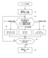
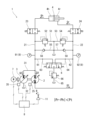
- FIG. 1 is a schematic configuration diagram of a hydraulic system according to an embodiment. It is a flowchart at the time of cylinder extension.
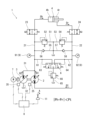
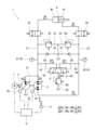
- FIG. 6 is a diagram showing the flow of hydraulic fluid when the differential pressure between the pressure in the head side chamber and the pressure in the rod side chamber is less than a threshold value when the cylinder is extended.
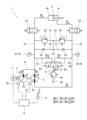
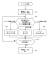
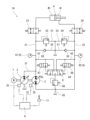
- FIG. 6 is a diagram showing the flow of hydraulic fluid when the differential pressure between the pressure in the head-side chamber and the pressure in the rod-side chamber is equal to or higher than a threshold value when the cylinder is extended. It is a flowchart when a cylinder is shortened.
- FIG. 6 is a diagram showing the flow of hydraulic fluid when the differential pressure between the pressure in the head side chamber and the pressure in the rod side chamber is less than a threshold value when the cylinder is extended.
- FIG. 6 is a diagram showing the flow of hydraulic fluid when the differential pressure between the pressure in the head-side chamber and the pressure in the rod-side chamber is equal to or higher than a threshold value when the cylinder is
- FIG. 6 is a diagram showing the flow of hydraulic fluid when the cylinder is shortened and the pressure difference between the pressure in the head side chamber and the pressure in the rod side chamber is less than a threshold value.
- FIG. 6 is a diagram showing the flow of hydraulic fluid when the cylinder is shortened and the pressure difference between the pressure in the head side chamber and the pressure in the rod side chamber is equal to or higher than a threshold value.
- It is a schematic block diagram of the hydraulic system of a modification.
- FIG. 1 is a schematic configuration diagram of a conventional hydraulic system.
- FIG. 1 shows a hydraulic system 1 according to an embodiment.
- This hydraulic system 1 is a hydraulic system for a single rod cylinder 4 including a head side chamber 4h and a rod side chamber 4r.
- the hydraulic fluid used in the hydraulic system 1 is typically oil.
- the hydraulic system 1 includes a first bidirectional pump 2 connected to the single rod cylinder 4 to form a closed circuit, and a flow rate difference ( It includes a second bidirectional pump 3 for eliminating the difference between the inflow flow rate and the outflow flow rate.
- the first bidirectional pump 2 is connected to the head side chamber 4h of the single rod cylinder 4 through a head side line 21, and is connected to the rod side chamber 4r of the single rod cylinder 4 through a rod side line 22.
- the second bidirectional pump 3 is connected to the head side line 21 through a first supply/discharge line 31 and to the tank through a second supply/discharge line 32 .
- the head side line 21 is provided with a first lock valve 23 that is an on-off valve
- the rod side line 22 is provided with a second lock valve 24 that is an on-off valve.
- the first lock valve 23 and the second lock valve 24 are controlled by the control device 8. Note that in FIG. 1, drawings of some signal lines are omitted to simplify the drawing.
- the control device 8 opens the first lock valve 23 and the second lock valve 24 when operating (extending or shortening) the single rod cylinder 4, and opens the first lock valve 23 and the second lock valve 24 at other times. close. By closing the first lock valve 23 and the second lock valve 24 in this manner, the operation of the single rod cylinder 4 can be locked.
- a head side relief line 51 branches from the head side line 21, and this head side relief line 51 is connected to the tank.
- the head side relief line 51 is provided with a head side relief valve 52 having a relatively high relief pressure (for example, 25 to 35 MPa).
- a first bypass line 55 that bypasses the head side relief valve 52 is branched from the head side line 21, and this first bypass line 55 is connected to the tank.
- the first bypass line 55 is provided with a first check valve 56 that allows flow from the tank toward the head side line 21 but prohibits flow in the opposite direction.
- the head side relief line 51 and the first bypass line 55 are branched from the head side line 21 between the first lock valve 23 and the first bidirectional pump 2, but the head side relief line 51 and the first bypass line 55 may branch from the head side line 21 between the first lock valve 23 and the single rod cylinder 4. Further, the first bypass line 55 does not necessarily need to branch from the head side line 21, and may branch from the head side relief line 51 on the upstream side of the head side relief valve 52.
- a rod-side relief line 53 branches off from the rod-side line 22, and this rod-side relief line 53 is connected to the tank.
- the rod-side relief line 53 is provided with a rod-side relief valve 54 having a relatively high relief pressure (for example, 25 to 35 MPa).
- a second bypass line 57 that bypasses the rod-side relief valve 54 is branched from the rod-side line 22, and this second bypass line 57 is connected to the tank.
- the second bypass line 57 is provided with a second check valve 58 that allows flow from the tank toward the rod side line 22 but prohibits flow in the opposite direction.
- the rod side relief line 53 and the second bypass line 57 are branched from the rod side line 22 between the second lock valve 24 and the first bidirectional pump 2, but the rod side relief line 53 and the second bypass line 57 may branch from the rod side line 22 between the second lock valve 24 and the single rod cylinder 4. Further, the second bypass line 57 does not necessarily need to branch from the rod side line 22, and may branch from the rod side relief line 53 on the upstream side of the rod side relief valve 54.
- the pressure Ph of the head side chamber 4h and the pressure Pr of the rod side chamber 4r can be kept below the set pressure of the head side relief valve 52 and the rod side relief valve 54. can be kept.
- the hydraulic fluid can be replenished to the head side line 21 or the rod side line 22 via the first check valve 56 or the second check valve 58. Cavitation can be suppressed on the lower pressure side of the head side (head side chamber 4h and head side line 21) and the rod side (rod side chamber 4r and rod side line 22).
- the first bidirectional pump 2 and the second bidirectional pump 3 are, for example, axial piston pumps (swash plate pumps or oblique shaft pumps). Further, the first bidirectional pump 2 and the second bidirectional pump 3 are variable displacement pumps.
- the capacity of the first bidirectional pump 2 is changed by the first regulator 25, and the capacity of the second bidirectional pump 3 is changed by the second regulator 35.
- the first regulator 25 and the second regulator 35 are controlled by the control device 8.
- the first regulator 25 electrically changes the hydraulic pressure acting on the servo piston connected to the swash plate of the first bidirectional pump 2.
- it may be an electric actuator connected to the swash plate of the first bidirectional pump 2.
- the second bidirectional pump 3 is a swash plate pump
- the second regulator 35 electrically changes the hydraulic pressure acting on the servo piston connected to the swash plate of the second bidirectional pump 3.
- it may be an electric actuator connected to the swash plate of the second bidirectional pump 3.
- the first bidirectional pump 2 and the second bidirectional pump 3 are driven in the same direction by an electric motor 7.
- the first bidirectional pump 2 and the second bidirectional pump 3 may be arranged so that their central axes are coaxial (tandem type), or may be arranged so that their central axes are parallel ( parallel type).
- the electric motor 7 is controlled by a control device 8.
- the electric motor 7 drives the first bidirectional pump 2 and the second bidirectional pump 3 in the first direction when extending the single rod cylinder 4, and drives the first bidirectional pump 2 and the second bidirectional pump 3 when shortening the single rod cylinder 4.
- the bidirectional pump 3 is driven in a second direction opposite to the first direction. When the first bidirectional pump 2 and the second bidirectional pump 3 are driven in the first direction, they discharge the working fluid into the head side chamber 4h, and the first bidirectional pump 2 and the second bidirectional pump 3 are driven in the second direction. Then, they suck in the working fluid from the head side chamber 4h.
- this embodiment employs a low pressure selection valve 6 that is connected to the head side line 21 through a first exhaust line 61 and connected to the rod side line 22 through a second exhaust line 62.
- the low pressure selection valve 6 is connected to the tank by a low pressure relief line 65.
- the low pressure relief line 65 is provided with a low pressure relief valve 66 whose relief pressure is set to be relatively low (for example, 0.1 to 2 MPa).
- the low pressure selection valve 6 is switched between a neutral position (center position in FIG. 1), a head-side discharge position (right-hand position in FIG. 1), and a rod-side discharge position (left-hand position in FIG. 1).
- the neutral position the low pressure selection valve 6 blocks the first discharge line 61 and the second discharge line 62.
- the low pressure selection valve 6 blocks the second discharge line 62 and connects the first discharge line 61 with the low pressure relief line 65.
- the low pressure selection valve 6 blocks the first discharge line 61 and connects the second discharge line 62 with the low pressure relief line 65.
- the pressure Ph in the head side chamber 4h is guided to the low pressure selection valve 6 through the first pilot line 63, and the pressure Pr in the rod side chamber 4r is guided through the second pilot line 64.
- the first pilot line 63 is for switching the low pressure selection valve 6 from the neutral position to the rod side discharge position
- the second pilot line 64 is for switching the low pressure selection valve 6 from the neutral position to the head side discharge position.
- the first pilot line 63 and the second pilot line 64 branch from the first discharge line 61 and the second discharge line 62, respectively, but the first pilot line 63 may branch from the head side line 21.
- the second pilot line 64 may branch from the rod side line 22.
- the low pressure selection valve 6 is switched from the neutral position to the rod side discharge position when the pressure Ph in the head side chamber 4h is higher than the pressure Pr in the rod side chamber 4r by a threshold value Pt or more, and the pressure Pr in the rod side chamber 4r is changed to the rod side discharge position.
- the threshold value Pt is within the range of 0.5 to 3 MPa. Note that the threshold value Pt may be different between when the cylinder is extended and when the cylinder is shortened.
- the hydraulic system 1 includes a position detector 9 that detects whether the low pressure selection valve 6 is in a neutral position, a rod side discharge position, or a head side discharge position. Position detector 9 is electrically connected to control device 8 .
- the position detector 9 includes a pressure sensor 91 that measures the pressure Ph in the head side chamber 4h, a pressure sensor 92 that measures the pressure Pr in the rod side chamber 4r, and a calculation section.
- the calculation unit determines that the position of the low pressure selection valve 6 is the neutral position when
- the pressure sensors 91 and 92 are provided in the head side line 21 and the rod side line 22, but the pressure sensors 91 and 92 may be provided in the head side chamber 4h and the rod side chamber 4r. Further, the position detector 9 may include a stroke sensor provided in the low pressure selection valve 6 instead of the two pressure sensors.
- controller 8 the functionality of the elements disclosed herein may include general purpose processors, special purpose processors, integrated circuits, ASICs (Application Specific Integrated Circuits), conventional circuits configured or programmed to perform the disclosed functions, and/or a combination thereof.
- Processors are considered processing circuits or circuits because they include transistors and other circuits.
- a circuit, unit, or means is hardware that performs the recited functions or is hardware that is programmed to perform the recited functions.
- the hardware may be the hardware disclosed herein or other known hardware that is programmed or configured to perform the recited functions. If the hardware is a processor, which is considered a type of circuit, the circuit, means or unit is a combination of hardware and software, the software being used in the configuration of the hardware and/or the processor.
- a first operation signal that is an extension command for the single rod cylinder 4 and a second operation signal that is a shortening command for the single rod cylinder 4 are input to the control device 8 .
- an operating device 11 including an operating lever operated by a user is employed, and a first operating signal and a second operating signal are input from this operating device 11 to the control device 8.
- the operating device 11 may be omitted and the first operating signal and the second operating signal may be input from the unmanned system to the control device 8.
- the operating speed of the single rod cylinder 4 is determined by the angle of the operating lever of the operating device 11. Therefore, the first operation signal and the second operation signal include a speed command for the single rod cylinder 4. However, the first operation signal and the second operation signal may not include a speed command, and the single rod cylinder 4 may operate at a constant speed during extension and contraction.
- FIG. 2 is a flowchart when the single rod cylinder 4 is extended. As shown in FIG. 3, when the operating lever of the operating device 11 is tilted in the A direction, a first operating signal, which is an extension command for the single rod cylinder 4, is input from the operating device 11 to the control device 8.
- a first operating signal which is an extension command for the single rod cylinder 4
- the control device 8 rotates the electric motor 7 in the first direction (step S1).
- the first bidirectional pump 2 and the second bidirectional pump 3 are driven in the first direction, and the first bidirectional pump 2 sucks the working fluid through the rod side line 22, and the second bidirectional pump 3 is driven into the second supply/exhaust line. Hydraulic fluid is drawn in through line 32.
- the first bidirectional pump 2 discharges hydraulic fluid through the head side line 21, and the second bidirectional pump 3 discharges hydraulic fluid through the first supply/discharge line 31. That is, the working fluids discharged from the first bidirectional pump 2 and the second bidirectional pump 3 join together and are supplied to the head side chamber 4h.
- the control device 8 rotates the electric motor 7 at the rotation speed N according to the speed command.
- the control device 8 acquires the position of the low pressure selection valve 6 detected by the position detector 9 (step S2).
- the low pressure selection valve 6 is in the neutral position.
- the discharge flow rate Q1 of the first bidirectional pump the discharge flow rate Q2 of the second bidirectional pump 3, the inflow flow rate Qh and the outflow flow rate Qr of the single rod cylinder 4
- the first bypass line 55 or the Replenishment of hydraulic fluid from the tank through the two bypass line 57 and discharge of hydraulic fluid into the tank through the first discharge line 61 or the second discharge line 62 are not performed.
- the factors that cause the discharge flow rate Q1, Q2, inflow flow rate Qh, and outflow flow rate Qr to become unbalanced include the performance of the first regulator 25 and the second regulator 35, the efficiency and operation of the first bidirectional pump 2 and the second bidirectional pump 3. External leakage of liquid, aging, etc.
- the flow rate Qh flowing into the head side chamber 4h is the sum of the discharge flow rate Q1 of the first bidirectional pump 2 and the discharge flow rate Q2 of the second bidirectional pump 3.
- the discharge flow rate Q1 [L/min] of the first bidirectional pump 2 is the product of the capacity q1 [L/r] of the first bidirectional pump 2 and the rotation speed N [rpm]
- the discharge flow rate Q1 [L/min] of the second bidirectional pump 3 is The discharge flow rate Q2 [L/min] is obtained by multiplying the capacity q2 [L/r] of the second bidirectional pump 3 by the rotation speed N [rpm].
- the outflow flow rate Qr from the rod side chamber 4r is equal to the suction flow rate Q1 of the first bidirectional pump 2.
- step S6 the control device 8 stops the electric motor 7 (step S7).
- the stroke of the single rod cylinder 4 reaches a predetermined amount, there are two times: when the input of the first operation signal from the operating device 11 to the control device 8 is stopped, and when the single rod cylinder 4 has moved to the stroke end. included.
- the regulator 35 is controlled (step S4).
- the first predetermined amount ⁇ q1 is determined in consideration of the factors that cause the above-mentioned discharge flow rates Q1, Q2, inflow flow rate Qh, and outflow flow rate Qr to become unbalanced. For example, ⁇ q1 is within the range of 1 to 10% of qr2.
- the pressure Ph in the head side chamber 4h becomes higher than the pressure Pr in the rod side chamber 4r by a threshold value Pt or more, and the low pressure selection valve 6 moves to the rod side discharge position. Can be switched.
- the capacity q1 of the first bidirectional pump 2 is smaller than the first reference capacity qr1 by the first predetermined amount ⁇ q1, as shown in FIG. from there through the second discharge line 62, the low pressure selection valve 6 and the low pressure relief line 65.
- the second predetermined amount ⁇ q2 is determined in consideration of the factors that cause the above-mentioned discharge flow rates Q1, Q2, inflow flow rate Qh, and outflow flow rate Qr to become unbalanced.
- the second predetermined amount ⁇ q2 may be the same as or different from the first predetermined amount ⁇ q1 described above. For example, ⁇ q2 is within the range of 1 to 10% of qr2.
- the pressure Pr in the rod side chamber 4r becomes higher than the pressure Ph in the head side chamber 4h by a threshold value Pt or more, and the low pressure selection valve 6 moves to the head side discharge position. Can be switched.
- the capacity q2 of the second bidirectional pump 3 is larger than the second reference capacity qr2 by the second predetermined amount ⁇ q2, as shown in FIG. is discharged through the first discharge line 61, the low pressure selection valve 6 and the low pressure relief line 65.
- step S6 when the stroke of the single rod cylinder 4 reaches a predetermined amount (YES in step S6), the control device 8 The electric motor 7 is stopped (step S7).
- FIG. 5 is a flowchart when the single rod cylinder 4 is shortened.
- a second operating signal which is a shortening command for the single rod cylinder 4 is input from the operating device 11 to the control device 8.
- the control device 8 rotates the electric motor 7 in the second direction (step S11).
- the first bidirectional pump 2 and the second bidirectional pump 3 are driven in the second direction, and the first bidirectional pump 2 sucks the working fluid through the head side line 21, and the second bidirectional pump 3 is driven in the first supply/discharge direction. Hydraulic fluid is sucked in through line 31.
- the working fluid flowing out from the head side chamber 4h is divided into an amount directed toward the first bidirectional pump 2 and an amount directed toward the second bidirectional pump 3.
- the first bidirectional pump 2 discharges the working fluid through the rod side line 22, and the second bidirectional pump 3 discharges the working fluid through the second supply/discharge line 32.
- the control device 8 rotates the electric motor 7 at the rotation speed N according to the speed command.
- the control device 8 acquires the position of the low pressure selection valve 6 detected by the position detector 9 (step S12).
- the low pressure selection valve 6 is in the neutral position.
- the first bypass line 55 or the Replenishment of hydraulic fluid from the tank through the two bypass line 57 and discharge of hydraulic fluid into the tank through the first discharge line 61 or the second discharge line 62 are not performed.
- the factors that cause the discharge flow rate Q1, Q2, inflow flow rate Qr, and outflow flow rate Qh to become unbalanced include the performance of the first regulator 25 and the second regulator 35, the efficiency and operation of the first bidirectional pump 2 and the second bidirectional pump 3. External leakage of liquid, aging, etc.
- the inflow flow rate Qr into the rod side chamber 4r is equal to the discharge flow rate Q1 of the first bidirectional pump 2.
- the outflow flow rate Qh from the head side chamber 4h is the sum of the suction flow rate Q1 of the first bidirectional pump 2 and the suction flow rate Q2 of the second bidirectional pump 3.
- step S16 the control device 8 stops the electric motor 7 (step S17).
- the stroke of the single rod cylinder 4 reaches a predetermined amount
- the input of the second operation signal from the operating device 11 to the control device 8 is stopped, and the single rod cylinder 4 operates to the stroke end. included.
- the third predetermined amount ⁇ q3 is determined in consideration of factors that cause the above-mentioned discharge flow rates Q1, Q2, inflow flow rate Qh, and outflow flow rate Qr to become unbalanced.
- the third predetermined amount ⁇ q3 may be the same as one of the first predetermined amount ⁇ q1 and the second predetermined amount ⁇ q2 described above, or may be different from either the first predetermined amount ⁇ q1 or the second predetermined amount ⁇ q2.
- ⁇ q3 is within the range of 1 to 10% of qr2.
- the pressure Pr in the rod side chamber 4r becomes higher than the pressure Ph in the head side chamber 4h by more than a threshold value Pt, and the low pressure selection valve 6 moves to the head side discharge position. Can be switched.
- the capacity q2 of the second bidirectional pump 3 is smaller than the second reference capacity qr2 by the third predetermined amount ⁇ q3, as shown in FIG. is discharged through the first discharge line 61, the low pressure selection valve 6 and the low pressure relief line 65.
- the regulator 35 is controlled (step S14).
- the fourth predetermined amount ⁇ q4 is determined in consideration of factors that cause the above-mentioned discharge flow rates Q1, Q2, inflow flow rate Qh, and outflow flow rate Qr to become unbalanced.
- the fourth predetermined amount ⁇ q4 may be the same as any of the above-described first predetermined amount ⁇ q1, second predetermined amount ⁇ q2, and third predetermined amount ⁇ q3, or may be the same as the first predetermined amount ⁇ q1, the second predetermined amount ⁇ q2, and the third predetermined amount ⁇ q3. It may be different from any of the three predetermined amounts ⁇ q3. For example, ⁇ q4 is within the range of 1 to 10% of qr2.
- the pressure Ph in the head side chamber 4h becomes higher than the pressure Pr in the rod side chamber 4r by a threshold value Pt or more, and the low pressure selection valve 6 moves to the rod side discharge position. Can be switched.
- the capacity q1 of the first bidirectional pump 2 is larger than the first reference capacity qr1 by the fourth predetermined amount ⁇ q4, as shown in FIG. from there through the second discharge line 62, the low pressure selection valve 6 and the low pressure relief line 65.
- step S16 when the stroke of the single rod cylinder 4 reaches a predetermined amount (YES in step S16), the control device 8 The electric motor 7 is stopped (step S17).
- the low pressure selection valve 6 is provided, so in a configuration in which the second bidirectional pump 3 is added to the first bidirectional pump 2, the rod side and head Pressure entrapment can be physically prevented from occurring on the lower pressure side. Furthermore, since the position of the low pressure selection valve 6 is detected by the position detector 9, various controls can be performed based on the position of the low pressure selection valve.
- the direction of the load is reversed when the single rod cylinder 4 is extended, and the low pressure selection valve 6 is moved from the rod side discharge position to the head side discharge position. , or even when switching from the head side discharge position to the rod side discharge position, the operating speed of the single rod cylinder 4 can be kept constant.
- control as shown in the flowchart shown in FIG. 5 is performed, so when the single rod cylinder 4 is shortened, the direction of the load is reversed and the low pressure selection valve 6 is moved from the rod side discharge position to the head side discharge position. , or even when switching from the head side discharge position to the rod side discharge position, the operating speed of the single rod cylinder 4 can be kept constant.
- the first pilot line 63 may be provided with a first on-off valve 67
- the second pilot line 64 may be provided with a second on-off valve 68.
- the present disclosure is a hydraulic system for a single rod cylinder including a head side chamber and a rod side chamber, the system being connected to the head side chamber by a head side line, and connected to the rod side chamber by a rod side line.
- a variable displacement first bidirectional pump connected to the head side line
- a variable displacement second bidirectional pump connected to the head side line by a supply/discharge line
- the first bidirectional pump and the second bidirectional pump connected in the same direction.
- a driving electric motor is connected to the head side line by a first discharge line and connected to the rod side line by a second discharge line, and the pressure difference between the pressure in the head side chamber and the pressure in the rod side chamber is a threshold value.
- the second discharge line When the pressure in the head side chamber is higher than the pressure in the rod side chamber by the threshold value or more, the second discharge line is located at a neutral position blocking the first discharge line and the second discharge line. is switched to a rod side discharge position in which the first discharge line is communicated with a relief line provided with a relief valve, and when the pressure in the rod side chamber is higher than the pressure in the head side chamber by the threshold value or more, the first discharge line is communicated with the relief line.
- a low-pressure selection valve that is switched to a head-side discharge position, and a position detector that detects whether the low-pressure selection valve is in the neutral position, the rod-side discharge position, or the head-side discharge position. , providing hydraulic systems.
- the low pressure selection valve since the low pressure selection valve is provided, in a configuration in which the second bidirectional pump is added to the first bidirectional pump, the pressure is closed on the rod side or the head side, whichever has the lower pressure. It is possible to physically prevent crowding from occurring. Moreover, since the position of the low pressure selection valve is detected by the position detector, various controls can be performed based on the position of the low pressure selection valve.
- the above hydraulic system includes: a first regulator that changes the capacity of the first bidirectional pump; a second regulator that changes the capacity of the second bidirectional pump; an electric motor, a control device that controls the first regulator and the second regulator, and the control device controls the position of the low pressure selection valve detected by the position detector when extending the single rod cylinder. is the neutral position, the capacity of the first bidirectional pump becomes the first reference capacity, the capacity of the second bidirectional pump becomes the second reference capacity, and the low pressure selection detected by the position detector When the valve position is at the rod side discharge position, the capacity of the first bidirectional pump is smaller than the first reference capacity by a first predetermined amount, and the capacity of the second bidirectional pump is smaller than the second reference capacity.
- the capacity of the first bidirectional pump becomes the first reference capacity.
- the first regulator and the second regulator may be controlled such that the capacity of the second bidirectional pump is greater than the second reference capacity by a second predetermined amount. According to this configuration, even if the direction of the load is reversed when the single rod cylinder is extended and the low pressure selection valve is switched from the rod side discharge position to the head side discharge position or from the head side discharge position to the rod side discharge position. , the operating speed of the single rod cylinder can be kept constant.
- the above hydraulic system includes a first regulator that changes the capacity of the first bidirectional pump, and a second regulator that changes the capacity of the second bidirectional pump. and a control device that controls the electric motor, the first regulator, and the second regulator, the control device controlling the low pressure selection detected by the position detector when shortening the single rod cylinder.
- the valve position is at the neutral position
- the capacity of the first bidirectional pump becomes a first reference capacity
- the capacity of the second bidirectional pump becomes a second reference capacity, which are detected by the position detector.
- the position of the low pressure selection valve is the head side discharge position
- the capacity of the first bidirectional pump becomes the first reference capacity
- the capacity of the second bidirectional pump becomes the second reference capacity.
- the capacity of the first bidirectional pump decreases by a third predetermined amount and the position of the low pressure selection valve detected by the position detector is the rod side discharge position
- the capacity of the first bidirectional pump is less than the first reference capacity by a fourth predetermined amount.
- the first regulator and the second regulator may be controlled such that the capacity of the second bidirectional pump increases by a predetermined amount and becomes smaller than the second reference capacity by a fourth predetermined amount.
- the second reference capacity is obtained by multiplying the first reference capacity by the ratio of the pressure receiving area of the rod side chamber to the cross-sectional area of the rod of the single rod cylinder. It may be something that has been done.
- the above hydraulic system includes a first lock valve that is an on-off valve provided in the head side line and a first lock valve provided in the rod side line.
- the device may further include a second lock valve that is an on-off valve. According to this configuration, the operation of the single rod cylinder can be locked by closing the first lock valve and the second lock valve.
- the pressure in the head side chamber is introduced to the low pressure selection valve through a first pilot line, and the pressure in the rod side chamber is introduced through a second pilot line.
- the hydraulic system may further include a first on-off valve provided on the first pilot line and a second on-off valve provided on the second pilot line. According to this configuration, hunting of the low pressure selection valve can be prevented by closing the first on-off valve and the second on-off valve in a situation where the magnitude relationship between the pressure in the head side chamber and the pressure in the rod side chamber is reversed. .
- the above hydraulic system includes a head side relief valve provided in a head side relief line branching from the head side line, and a head side relief valve provided in a head side relief line branching from the head side line.
- a first check valve provided in a first bypass line that bypasses the valve, a rod side relief valve provided in a rod side relief line branching from the rod side line, and a second bypass that bypasses the rod side relief valve.
- the apparatus may further include a second check valve provided in the line.
- the pressure in the head side chamber and the pressure in the rod side chamber can be maintained below the set pressure of the relief valve, and the hydraulic fluid is supplied to the head side line or the rod side line via the check valve, so that the pressure in the head side chamber and the pressure in the rod side chamber can be kept below the set pressure of the relief valve. Cavitation can be suppressed on the lower pressure side of the rod.
Landscapes
- Engineering & Computer Science (AREA)
- General Engineering & Computer Science (AREA)
- Physics & Mathematics (AREA)
- Fluid Mechanics (AREA)
- Mining & Mineral Resources (AREA)
- Civil Engineering (AREA)
- Structural Engineering (AREA)
- Mechanical Engineering (AREA)
- Chemical & Material Sciences (AREA)
- Analytical Chemistry (AREA)
- Fluid-Pressure Circuits (AREA)
Abstract
Description
図2は、片ロッドシリンダ4を伸長させるときのフローチャートである。図3に示すように、操作装置11の操作レバーがA方向に傾倒されると、操作装置11から制御装置8へ片ロッドシリンダ4に対する伸長指令である第1操作信号が入力される。
図5は、片ロッドシリンダ4を短縮させるときのフローチャートである。図6に示すように、操作装置11の操作レバーがB方向に傾倒されると、操作装置11から制御装置8へ片ロッドシリンダ4に対する短縮指令である第2操作信号が入力される。
本開示は上述した実施形態に限定されるものではなく、本開示の要旨を逸脱しない範囲で種々の変形が可能である。
第1の態様として、本開示は、ヘッド側室およびロッド側室を含む片ロッドシリンダ用の液圧システムであって、ヘッド側ラインにより前記ヘッド側室と接続されるとともに、ロッド側ラインにより前記ロッド側室と接続される可変容量型の第1両方向ポンプと、給排ラインにより前記ヘッド側ラインと接続される可変容量型の第2両方向ポンプと、前記第1両方向ポンプおよび前記第2両方向ポンプを同方向に駆動する電動モータと、第1排出ラインにより前記ヘッド側ラインと接続されるとともに第2排出ラインにより前記ロッド側ラインと接続され、前記ヘッド側室の圧力と前記ロッド側室の圧力との差圧が閾値未満のときは前記第1排出ラインおよび前記第2排出ラインをブロックする中立位置に位置し、前記へッド側室の圧力が前記ロッド側室の圧力よりも前記閾値以上高いときは前記第2排出ラインをリリーフ弁が設けられたリリーフラインと連通させるロッド側排出位置に切り換えられ、前記ロッド側室の圧力が前記ヘッド側室の圧力よりも前記閾値以上高いときは前記第1排出ラインを前記リリーフラインと連通させるヘッド側排出位置に切り換えられる低圧選択弁と、前記低圧選択弁の位置が前記中立位置、前記ロッド側排出位置および前記ヘッド側排出位置のいずれであるかを検出する位置検出器と、を備える、液圧システムを提供する。
Claims (7)
- ヘッド側室およびロッド側室を含む片ロッドシリンダ用の液圧システムであって、
ヘッド側ラインにより前記ヘッド側室と接続されるとともに、ロッド側ラインにより前記ロッド側室と接続される可変容量型の第1両方向ポンプと、
給排ラインにより前記ヘッド側ラインと接続される可変容量型の第2両方向ポンプと、
前記第1両方向ポンプおよび前記第2両方向ポンプを同方向に駆動する電動モータと、
第1排出ラインにより前記ヘッド側ラインと接続されるとともに第2排出ラインにより前記ロッド側ラインと接続され、前記ヘッド側室の圧力と前記ロッド側室の圧力との差圧が閾値未満のときは前記第1排出ラインおよび前記第2排出ラインをブロックする中立位置に位置し、前記へッド側室の圧力が前記ロッド側室の圧力よりも前記閾値以上高いときは前記第2排出ラインをリリーフ弁が設けられたリリーフラインと連通させるロッド側排出位置に切り換えられ、前記ロッド側室の圧力が前記ヘッド側室の圧力よりも前記閾値以上高いときは前記第1排出ラインを前記リリーフラインと連通させるヘッド側排出位置に切り換えられる低圧選択弁と、
前記低圧選択弁の位置が前記中立位置、前記ロッド側排出位置および前記ヘッド側排出位置のいずれであるかを検出する位置検出器と、
を備える、液圧システム。 - 前記第1両方向ポンプの容量を変更する第1レギュレータと、
前記第2両方向ポンプの容量を変更する第2レギュレータと、
前記電動モータ、前記第1レギュレータおよび前記第2レギュレータを制御する制御装置と、を備え、
前記制御装置は、前記片ロッドシリンダを伸長させる際、
前記位置検出器で検出される前記低圧選択弁の位置が前記中立位置であるときは、前記第1両方向ポンプの容量が第1基準容量となるとともに、前記第2両方向ポンプの容量が第2基準容量となり、
前記位置検出器で検出される前記低圧選択弁の位置が前記ロッド側排出位置であるときは、前記第1両方向ポンプの容量が前記第1基準容量よりも第1所定量だけ少なくなるとともに、前記第2両方向ポンプの容量が前記第2基準容量よりも前記第1所定量だけ多くなり、
前記位置検出器で検出される前記低圧選択弁の位置が前記ヘッド側排出位置であるときは、前記第1両方向ポンプの容量が前記第1基準容量となるとともに、前記第2両方向ポンプの容量が前記第2基準容量よりも第2所定量だけ多くなるように、
前記第1レギュレータおよび前記第2レギュレータを制御する、請求項1に記載の液圧システム。 - 前記第1両方向ポンプの容量を変更する第1レギュレータと、
前記第2両方向ポンプの容量を変更する第2レギュレータと、
前記電動モータ、前記第1レギュレータおよび前記第2レギュレータを制御する制御装置と、を備え、
前記制御装置は、前記片ロッドシリンダを短縮させる際、
前記位置検出器で検出される前記低圧選択弁の位置が前記中立位置であるときは、前記第1両方向ポンプの容量が第1基準容量となるとともに、前記第2両方向ポンプの容量が第2基準容量となり、
前記位置検出器で検出される前記低圧選択弁の位置が前記ヘッド側排出位置であるときは、前記第1両方向ポンプの容量が前記第1基準容量となるとともに、前記第2両方向ポンプの容量が前記第2基準容量よりも前記第3所定量だけ少なくなり、
前記位置検出器で検出される前記低圧選択弁の位置が前記ロッド側排出位置であるときは、前記第1両方向ポンプの容量が前記第1基準容量よりも第4所定量だけ多くなるとともに、前記第2両方向ポンプの容量が前記第2基準容量よりも第4所定量だけ少なくなるように、
前記第1レギュレータおよび前記第2レギュレータを制御する、請求項1または2に記載の液圧システム。 - 前記第2基準容量は、前記第1基準容量に前記片ロッドシリンダのロッドの断面積に対する前記ロッド側室の受圧面積の比を乗算したものである、請求項2に記載の液圧システム。
- 前記ヘッド側ラインに設けられた、開閉弁である第1ロック弁と、
前記ロッド側ラインに設けられた、開閉弁である第2ロック弁と、をさらに備える、請求項1に記載の液圧システム。 - 前記低圧選択弁には、第1パイロットラインを通じて前記ヘッド側室の圧力が導かれるとともに、第2パイロットラインを通じて前記ロッド側室の圧力が導かれ、
前記第1パイロットラインに設けられた第1開閉弁と、
前記第2パイロットラインに設けられた第2開閉弁と、をさらに備える、請求項1に記載の液圧システム。 - 前記ヘッド側ラインから分岐するヘッド側リリーフラインに設けられたヘッド側リリーフ弁と、
前記ヘッド側リリーフ弁をバイパスする第1バイパスラインに設けられた第1チェック弁と、
前記ロッド側ラインから分岐するロッド側リリーフラインに設けられたロッド側リリーフ弁と、
前記ロッド側リリーフ弁をバイパスする第2バイパスラインに設けられた第2チェック弁と、をさらに備える、請求項1に記載の液圧システム。
Priority Applications (3)
| Application Number | Priority Date | Filing Date | Title |
|---|---|---|---|
| DE112023003036.7T DE112023003036T5 (de) | 2022-07-11 | 2023-04-19 | Hydrauliksystem |
| CN202380053023.6A CN119546860A (zh) | 2022-07-11 | 2023-04-19 | 液压系统 |
| US18/993,470 US20260022717A1 (en) | 2022-07-11 | 2023-04-19 | Hydraulic system |
Applications Claiming Priority (2)
| Application Number | Priority Date | Filing Date | Title |
|---|---|---|---|
| JP2022111246A JP2024009598A (ja) | 2022-07-11 | 2022-07-11 | 液圧システム |
| JP2022-111246 | 2022-07-11 |
Publications (1)
| Publication Number | Publication Date |
|---|---|
| WO2024014083A1 true WO2024014083A1 (ja) | 2024-01-18 |
Family
ID=89536414
Family Applications (1)
| Application Number | Title | Priority Date | Filing Date |
|---|---|---|---|
| PCT/JP2023/015570 Ceased WO2024014083A1 (ja) | 2022-07-11 | 2023-04-19 | 液圧システム |
Country Status (5)
| Country | Link |
|---|---|
| US (1) | US20260022717A1 (ja) |
| JP (1) | JP2024009598A (ja) |
| CN (1) | CN119546860A (ja) |
| DE (1) | DE112023003036T5 (ja) |
| WO (1) | WO2024014083A1 (ja) |
Cited By (1)
| Publication number | Priority date | Publication date | Assignee | Title |
|---|---|---|---|---|
| US12618467B2 (en) * | 2022-07-11 | 2026-05-05 | Kawasaki Jukogyo Kabushiki Kaisha | Hydraulic system |
Citations (1)
| Publication number | Priority date | Publication date | Assignee | Title |
|---|---|---|---|---|
| JP2002021807A (ja) * | 2000-07-10 | 2002-01-23 | Kobelco Contstruction Machinery Ltd | 電動液圧駆動装置及びアクチュエータ駆動装置 |
Family Cites Families (1)
| Publication number | Priority date | Publication date | Assignee | Title |
|---|---|---|---|---|
| JP6476074B2 (ja) * | 2015-06-03 | 2019-02-27 | 日立建機株式会社 | 作業機械 |
-
2022
- 2022-07-11 JP JP2022111246A patent/JP2024009598A/ja active Pending
-
2023
- 2023-04-19 CN CN202380053023.6A patent/CN119546860A/zh active Pending
- 2023-04-19 DE DE112023003036.7T patent/DE112023003036T5/de active Pending
- 2023-04-19 US US18/993,470 patent/US20260022717A1/en active Pending
- 2023-04-19 WO PCT/JP2023/015570 patent/WO2024014083A1/ja not_active Ceased
Patent Citations (1)
| Publication number | Priority date | Publication date | Assignee | Title |
|---|---|---|---|---|
| JP2002021807A (ja) * | 2000-07-10 | 2002-01-23 | Kobelco Contstruction Machinery Ltd | 電動液圧駆動装置及びアクチュエータ駆動装置 |
Cited By (1)
| Publication number | Priority date | Publication date | Assignee | Title |
|---|---|---|---|---|
| US12618467B2 (en) * | 2022-07-11 | 2026-05-05 | Kawasaki Jukogyo Kabushiki Kaisha | Hydraulic system |
Also Published As
| Publication number | Publication date |
|---|---|
| US20260022717A1 (en) | 2026-01-22 |
| JP2024009598A (ja) | 2024-01-23 |
| CN119546860A (zh) | 2025-02-28 |
| DE112023003036T5 (de) | 2025-10-02 |
Similar Documents
| Publication | Publication Date | Title |
|---|---|---|
| US5571226A (en) | Hydraulic device for construction machinery | |
| JP6831711B2 (ja) | 液圧駆動システム | |
| WO2013027620A1 (ja) | 油圧駆動システム | |
| CN101253335A (zh) | 用于控制双作用液压驱动缸的油路 | |
| US6886332B2 (en) | Bi-rotational, two-stage hydraulic system | |
| KR100984142B1 (ko) | 액압 구동 장치 | |
| JP2024009598A (ja) | 液圧システム | |
| JP3922577B2 (ja) | 両回転形液圧ポンプ装置 | |
| CN120344774A (zh) | 液压系统 | |
| CN111108292B (zh) | 液压系统 | |
| WO2002004820A1 (fr) | Circuit de verin hydraulique | |
| CN111664135A (zh) | 齿轮齿条升降平台的液压系统 | |
| WO2024014082A1 (ja) | 液圧システム | |
| US8443827B2 (en) | Controlling device for hydraulic consumers | |
| JP2002021807A (ja) | 電動液圧駆動装置及びアクチュエータ駆動装置 | |
| US5291821A (en) | Hydraulic circuit for swivel working machine | |
| KR100813774B1 (ko) | 소형 굴삭기의 유압펌프 제어장치 | |
| CN111608969B (zh) | 控制装置和施工机械 | |
| JP2003343511A (ja) | 建設機械の油圧駆動装置 | |
| CN113217486B (zh) | 流体压系统和流体压的控制方法 | |
| CN120322624A (zh) | 液压系统 | |
| JP2002106504A (ja) | 油圧ポンプの容量制御装置 | |
| JP2000038991A (ja) | 油圧ポンプの制御装置 | |
| WO2025203798A1 (ja) | 建設機械の油圧システム | |
| KR20250003297A (ko) | 유압 회로 |
Legal Events
| Date | Code | Title | Description |
|---|---|---|---|
| 121 | Ep: the epo has been informed by wipo that ep was designated in this application |
Ref document number: 23839261 Country of ref document: EP Kind code of ref document: A1 |
|
| WWE | Wipo information: entry into national phase |
Ref document number: 202380053023.6 Country of ref document: CN Ref document number: 18993470 Country of ref document: US |
|
| WWE | Wipo information: entry into national phase |
Ref document number: 112023003036 Country of ref document: DE |
|
| WWP | Wipo information: published in national office |
Ref document number: 202380053023.6 Country of ref document: CN |
|
| 122 | Ep: pct application non-entry in european phase |
Ref document number: 23839261 Country of ref document: EP Kind code of ref document: A1 |
|
| WWP | Wipo information: published in national office |
Ref document number: 112023003036 Country of ref document: DE |
|
| WWP | Wipo information: published in national office |
Ref document number: 18993470 Country of ref document: US |