WO2024010064A1 - 細胞培養装置及び細胞培養方法 - Google Patents
細胞培養装置及び細胞培養方法 Download PDFInfo
- Publication number
- WO2024010064A1 WO2024010064A1 PCT/JP2023/025128 JP2023025128W WO2024010064A1 WO 2024010064 A1 WO2024010064 A1 WO 2024010064A1 JP 2023025128 W JP2023025128 W JP 2023025128W WO 2024010064 A1 WO2024010064 A1 WO 2024010064A1
- Authority
- WO
- WIPO (PCT)
- Prior art keywords
- culture solution
- solution storage
- culture
- hydrogel
- storage tank
- Prior art date
- Legal status (The legal status is an assumption and is not a legal conclusion. Google has not performed a legal analysis and makes no representation as to the accuracy of the status listed.)
- Ceased
Links
Images


Classifications
-
- C—CHEMISTRY; METALLURGY
- C12—BIOCHEMISTRY; BEER; SPIRITS; WINE; VINEGAR; MICROBIOLOGY; ENZYMOLOGY; MUTATION OR GENETIC ENGINEERING
- C12M—APPARATUS FOR ENZYMOLOGY OR MICROBIOLOGY; APPARATUS FOR CULTURING MICROORGANISMS FOR PRODUCING BIOMASS, FOR GROWING CELLS OR FOR OBTAINING FERMENTATION OR METABOLIC PRODUCTS, i.e. BIOREACTORS OR FERMENTERS
- C12M1/00—Apparatus for enzymology or microbiology
-
- C—CHEMISTRY; METALLURGY
- C12—BIOCHEMISTRY; BEER; SPIRITS; WINE; VINEGAR; MICROBIOLOGY; ENZYMOLOGY; MUTATION OR GENETIC ENGINEERING
- C12M—APPARATUS FOR ENZYMOLOGY OR MICROBIOLOGY; APPARATUS FOR CULTURING MICROORGANISMS FOR PRODUCING BIOMASS, FOR GROWING CELLS OR FOR OBTAINING FERMENTATION OR METABOLIC PRODUCTS, i.e. BIOREACTORS OR FERMENTERS
- C12M3/00—Tissue, human, animal or plant cell, or virus culture apparatus
-
- C—CHEMISTRY; METALLURGY
- C12—BIOCHEMISTRY; BEER; SPIRITS; WINE; VINEGAR; MICROBIOLOGY; ENZYMOLOGY; MUTATION OR GENETIC ENGINEERING
- C12N—MICROORGANISMS OR ENZYMES; COMPOSITIONS THEREOF; PROPAGATING, PRESERVING, OR MAINTAINING MICROORGANISMS; MUTATION OR GENETIC ENGINEERING; CULTURE MEDIA
- C12N5/00—Undifferentiated human, animal or plant cells, e.g. cell lines; Tissues; Cultivation or maintenance thereof; Culture media therefor
- C12N5/06—Animal cells or tissues; Human cells or tissues
Definitions
- the present invention relates to a cell culture device and a cell culture method.
- This application claims priority based on Japanese Patent Application No. 2022-110291 filed in Japan on July 8, 2022, the contents of which are incorporated herein.
- Patent Document 1 discloses a microchannel device.
- the microfluidic device comprises a substrate made of an optically transparent material and further includes one or more fluid channels, one or more fluid channel inlets, one or more fluid channel outlets, It includes one or more gel cage regions and a plurality of struts. All or a portion of each gel cage region is flanked by all or a portion of one or more fluid channels, thereby creating one or more gel cage region-fluid channel interface regions.
- Each gel cage region includes at least one row of struts forming the gel cage region, the at least one row of struts with each strut formed as a triangle, a trapezoid with an interior angle of less than 90°, or a combination thereof.
- the sum of the inner angle of each strut corner and the contact angle of the gel on the substrate surface in at least one strut row is 180°, and the distance between each adjacent pair of struts in at least one strut row is The distance is said to be 50 micrometers to 300 micrometers.
- vascular endothelial cells have been placed inside or near a hydrogel to spontaneously construct vascular tissue.
- Cell culture methods are known.
- this method has limitations on the size of vascular tissue that can be constructed due to limitations on the supply of oxygen and nutrients into the hydrogel.
- the present invention has been made in view of the above problems, and aims to provide a cell culture device and a cell culture method that can efficiently construct large cell tissues in vitro.
- a cell culture device includes a hydrogel chamber that holds a hydrogel for culturing cells, a first culture fluid storage portion that communicates with a first surface of the hydrogel chamber, and a first culture fluid storage portion that communicates with a first surface of the hydrogel chamber.
- a culture container including a second culture solution reservoir communicating with a second surface different from the first surface; and a pneumatic device connected to the culture container, the pneumatic device being connected to the first surface.
- Culture stored in at least one of the first culture solution storage section and the second culture solution storage section by creating a pressure difference based on air pressure between the culture solution storage section and the second culture solution storage section. The liquid is infiltrated into the hydrogel in the hydrogel chamber under pressure.
- At least one of the first culture solution storage section and the second culture solution storage section includes a culture solution storage tank that stores a culture solution, and the culture solution storage tank. and a microchannel communicating with the hydrogel chamber.
- the microchannel may be provided with one or a plurality of resistance channels having a smaller cross-sectional area than the microchannel.
- the flow path resistance (R MC ) of the resistance flow path is determined by the viscosity ( ⁇ ) of the culture solution, the viscosity ( ⁇ ) of the culture solution, and the range from the first surface to the second surface of the hydrogel chamber.
- the relationship R MC ⁇ 8 ⁇ L/ ⁇ d 4 N may be satisfied.
- a pair of the microchannels may be provided.
- the first culture solution storage section includes a first culture solution storage tank as the culture solution storage tank and a first microchannel as the microchannel.
- the second culture solution storage unit includes a second culture solution storage tank as the culture solution storage tank and a second microchannel as the microchannel, and the second culture solution storage unit includes a second culture solution storage tank as the culture solution storage tank and a second microchannel as the microchannel, and the second culture solution storage unit includes a second culture solution storage tank as the culture solution storage tank and a second microchannel as the microchannel.
- a culture solution return channel that communicates with the second culture solution storage tank, at least one of the first microchannel and the second microchannel, and a mechanism for preventing backflow of the culture solution are provided in the return channel. You may prepare.
- a passive valve that prevents air bubbles from entering may be provided as the mechanism for preventing the backflow.
- the pressure resistance of the passive valve may be within a range of 0.1 [kPa] to 10 [kPa].
- an opening may be formed directly above the hydrogel chamber.
- a third culture solution storage portion communicating through the opening is provided, and the second opening has one side facing the hydrogel.
- a permeable membrane whose other side faces the culture solution may be provided.
- the pneumatic device may be connected to the third culture fluid reservoir.
- the pneumatic device may include pneumatic piping connected to the culture container, and the pneumatic piping may be provided with a filter.
- the hydrogel chamber may include a mechanism for holding the hydrogel in a state where a pressure difference based on the air pressure is generated.
- cells are cultured in the hydrogel chamber using the cell culture device described above.
- the cells may be cultured to form vascular tissue within the hydrogel chamber.
- large cell tissues can be efficiently constructed in vitro.
- FIG. 2 is a sectional view taken along arrow II-II shown in FIG. 1.
- FIG. 3 is a sectional view taken along arrows III-III shown in FIG. 2.
- FIG. 4 is an enlarged view of area A shown in FIG. 3.
- FIG. It is a perspective view showing a cell culture device concerning a 2nd embodiment.
- 6 is a sectional view taken along arrow VI-VI shown in FIG. 5.
- FIG. 7 is a sectional view taken along arrow VII-VII shown in FIG. 6.
- FIG. 7 is a perspective view showing a cell culture device concerning a 3rd embodiment.
- FIG. 7 is a plan cross-sectional view showing main parts of a cell culture device according to a third embodiment.
- FIG. 7 is a plan cross-sectional view showing main parts of a cell culture device according to a third embodiment.
- FIG. 7 is a plan cross-sectional view showing main parts of a cell culture device according to a fourth embodiment. 11 is an enlarged view of region B shown in FIG. 10.
- FIG. It is a perspective view showing a cell culture device concerning a 5th embodiment. 13 is a sectional view taken along arrows XIII-XIII shown in FIG. 12.
- FIG. 14 is a cross-sectional view taken along arrows XIV-XIV shown in FIG. 13.
- FIG. It is a perspective view showing a cell culture device concerning a 6th embodiment.
- 16 is a sectional view taken along arrows XVI-XVI shown in FIG. 15.
- FIG. 17 is a sectional view taken along arrow XVII-XVII shown in FIG. 16.
- FIG. 16 is a sectional view taken along arrow XVII-XVII shown in FIG. 16.
- FIG. 7 is a schematic plan view showing a cell culture device according to an eighth embodiment.
- FIG. 7 is a schematic plan view showing a cell culture device according to a ninth embodiment. It is a graph showing the relationship between blood vessel diameter, shear stress, and flow rate according to the first example.
- It is a fluorescence microscopy image of vascular tissue in the case of “no resistance flow path” according to the first example.
- It is a fluorescence microscopy image of vascular tissue in the case of “with resistance flow path” according to the first example.
- It is a fluorescence microscope image of the entire vascular tissue in the case of "no resistance flow path” according to the first example.
- FIG. 3 is a schematic plan view showing a cell culture device according to a second example. These are fluorescence microscope images of Calcein immediately after and 50 seconds after pressurizing the culture container according to the second example at 2.0 [kPa]. Rhodamine-Dextran fluorescence interface when the culture container according to the second example is pressurized at 0.5 [kPa], 1.0 [kPa], 2.0 [kPa], and 3.0 [kPa] It is a graph showing the results of measuring the movement of .
- FIG. 7 is a fluorescence microscope image showing the formation behavior of blood vessels with and without mesenchymal stem cells according to the second example.
- FIG. 7 is a graph showing the change in blood flow rate in a blood vessel with and without mesenchymal stem cells according to a second example.
- FIG. 7 is a schematic plan view showing a cell culture device according to a modified example of the second embodiment.
- FIG. 7 is an image analysis diagram when determining the permeability coefficient of a fluorescent substance through a blood vessel wall in order to evaluate the barrier ability of a blood vessel tissue formed using a cell culture apparatus according to a second example and a modification thereof.
- FIG. 7 is a diagram showing an image in which vascular endothelial cells formed using the cell culture device according to the second embodiment and a modification thereof are stained with CD31, which is a marker, and an image in which NG2, which is a marker for mesenchymal stem cells, is stained. .
- FIG. 7 is a diagram showing images of vascular endothelial cells formed using the cell culture apparatus according to the second example and a modification thereof, stained with ZO-1, which constitutes tight junctions in the blood vessel wall.
- the present invention can be applied to vascular permeability testing of drug candidate compounds in drug discovery, organoid culture for regenerative medicine and cell assays, cancer invasion evaluation, and the like.
- drug discovery when evaluating the pharmacokinetics of a drug, the permeability of the drug to the blood vessel wall may be evaluated. It can be used as a method. In particular, it can be used as a device and test method that can accurately evaluate the permeability of the blood-brain barrier.
- organoid culture methods have recently attracted attention, and the cell culture device and cell culture method of the present invention can be used to culture vascularized organoids in order to further mature the organoids.
- distant metastasis of cancer is related to the movement of cancer cells through blood vessels, and the cell culture device and cell culture method of the present invention can be used as a model for evaluating cancer cell metastasis in drug discovery and clinical testing. Available.
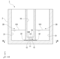
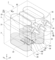
- FIG. 1 is a perspective view showing a cell culture device 1 according to the first embodiment.
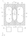
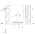
- FIG. 2 is a sectional view taken along arrow II-II shown in FIG.
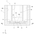
- FIG. 3 is a sectional view taken along arrows III-III shown in FIG.
- FIG. 4 is an enlarged view of area A shown in FIG.
- the cell culture device 1 includes a culture container 2 that holds a hydrogel 100 for culturing cells and stores a culture solution 101 that supplies oxygen, nutrients, etc. to the cells.
- the culture container 2 is preferably formed of a transparent material with high light transmittance for purposes such as observation of cells, but may be formed of a material with low light transmittance or no light transmittance. In that case, a glass window or the like may be provided at a position where the cells can be visually recognized.
- the culture container 2 includes a hydrogel chamber 10, a first culture solution storage section 20, and a second culture solution storage section 30.
- Hydrogel chamber 10 is arranged between first culture solution reservoir 20 and second culture solution reservoir 30. In the example shown in FIG. 1, the hydrogel chamber 10 is arranged horizontally adjacent to the first culture solution storage section 20 and the second culture solution storage section 30.
- the X-axis direction is the first horizontal direction in which the first culture solution storage section 20, the hydrogel chamber 10, and the second culture solution storage section 30 are lined up.
- the Y-axis direction is a second horizontal direction orthogonal to the X-axis direction.
- the Z-axis direction is a vertical direction orthogonal to the X-axis direction and the Y-axis direction.
- the hydrogel chamber 10 has a flat internal space 11.
- the height (dimension in the Z-axis direction) of the internal space 11 of the hydrogel chamber 10 is, for example, within the range of 100 [ ⁇ m] to 500 [ ⁇ m].
- the internal space 11 of the hydrogel chamber 10 is filled with hydrogel 100.
- the hydrogel 100 has a three-dimensional polymer network structure and retains water, and also embeds or adheres cells to culture the cells.
- the hydrogel chamber 10 is formed into a hexagonal shape when viewed from above.
- the shape of the hydrogel chamber 10 in plan view is not particularly limited, but the length (dimension in the Y-axis direction) adjacent to the first culture solution storage section 20 and the second culture solution storage section 30 is the same as the width (dimension in the X-axis direction). (dimensions) is better.
- the dimension of the hydrogel chamber 10 in the Y-axis direction is, for example, within the range of 1 [mm] to 20 [mm].
- the dimension of the hydrogel chamber 10 in the X-axis direction is, for example, within a range of 1 [mm] to 10 [mm].
- the hydrogel chamber 10 has a first surface 12 that communicates with the first culture solution reservoir 20 and a second surface 13 that communicates with the second culture solution reservoir 30.
- the first surface 12 and the second surface 13 face each other in the X-axis direction and extend parallel to each other in the Y-axis direction. Both ends of the hydrogel chamber 10 in the Y-axis direction communicate with introduction holes 14 and 15 via introduction paths 14a and 15a.
- a hydrogel storage tank 16 into which the hydrogel 100 is introduced is formed directly above the hydrogel chamber 10 .
- the introduction hole 14 connects the top surface of the hydrogel chamber 10 and the bottom surface of the hydrogel storage tank 16 at one end side (-Y side) of the hydrogel chamber 10 in the Y-axis direction.
- the introduction hole 15 allows the top surface of the hydrogel chamber 10 and the bottom surface of the hydrogel storage tank 16 to communicate with each other on the other end side (+Y side) of the hydrogel chamber 10 in the Y-axis direction.
- the two introduction holes 14 and 15 facilitate removing air from the hydrogel chamber 10 and filling the hydrogel chamber 10 with the hydrogel 100 from the hydrogel storage tank 16.
- the first culture solution storage section 20 includes a first culture solution storage tank 21 that stores the culture solution 101.
- the first culture solution storage tank 21 is formed in a long hole shape or an elliptical shape extending in the Y-axis direction when viewed from above. Note that the shape of the first culture solution storage tank 21 in plan view is not particularly limited.
- the first culture solution storage tank 21 preferably has a larger internal space (volume) than the hydrogel chamber 10. The side surface of the bottom of the first culture solution storage tank 21 on the hydrogel chamber 10 side (+X side) communicates with the first surface 12 of the hydrogel chamber 10 .
- the second culture solution storage section 30 includes a second culture solution storage tank 31 that stores the culture solution 101.
- the second culture solution storage tank 31 is formed in a long hole shape or an elliptical shape extending in the Y-axis direction when viewed from above. Note that the planar shape of the second culture solution storage tank 31 is not particularly limited.
- the second culture solution storage tank 31 also preferably has a larger internal space (volume) than the hydrogel chamber 10. The side surface of the bottom of the second culture solution storage tank 31 on the hydrogel chamber 10 side (-X side) communicates with the second surface 13 of the hydrogel chamber 10.
- the culture container 2 configured as described above is connected to a pneumatic device 5, as shown in FIG.
- the pneumatic device 5 includes a pneumatic pump 50 connected to the first culture solution storage tank 21 and a pneumatic pump 60 connected to the second culture solution storage tank 31.
- the pneumatic pumps 50 and 60 can continuously pressurize the inside of the culture container 2, for example, while a motor (not shown) is being driven.
- the pneumatic device 5 generates a pressure difference based on pneumatic pressure between the first culture solution storage tank 21 and the second culture solution storage tank 31, so that the first culture solution storage tank 21 and the second culture solution storage tank 31 is infiltrated into the hydrogel 100 of the hydrogel chamber 10 under pressure.
- the empty Either one of the pressure pumps 50 and 60 may be omitted.
- pneumatic piping is branched from one pneumatic pump and connected to each of the first culture solution storage tank 21 and the second culture solution storage tank 31, and a switching valve is provided in the branch pipe of the pneumatic pipe, The culture solution storage tank to which air pressure is applied may be changed.
- the pneumatic device 5 is equipped with a pressure regulator (not shown), for example, and adjusts the pressure within the range of 0.1 [kPa] to 10 [kPa]. Pressurize at least one of them.
- the culture container 2 is equipped with strut rows 22 and 32 as a mechanism for holding the hydrogel 100 in the hydrogel chamber 10 even when a pressure difference based on the air pressure is generated. Furthermore, the hydrogel chamber 10 may be subjected to a surface treatment to retain the hydrogel 100 (such as a coating treatment to adjust surface wettability).
- the column row 22 is provided along the first surface 12 of the hydrogel chamber 10 that communicates with the first culture solution storage tank 21.
- the height of the strut row 22 is the same as the height of the internal space 11 of the hydrogel chamber 10. Further, the distance between each pillar of the pillar row 22 is within a range of, for example, 50 [ ⁇ m] to 300 [ ⁇ m]. The detailed structure of the strut row 22 will be described below with reference to FIG. 4.
- the column row 22 includes a plurality of columns 40 that form an interface area between the hydrogel chamber 10 and the first culture solution storage tank 21.
- the pillars 40 are formed at equal intervals with gaps in the Y-axis direction.
- a fluid channel that communicates with the hydrogel chamber 10 and the first culture solution storage tank 21 is formed between the pillars 40 adjacent in the Y-axis direction.
- the support column 40 is formed into a substantially pentagonal shape in a plan cross-sectional view.
- the side surface of the support column 40 connects a pair of slopes 41 arranged on the side of the hydrogel chamber 10, a plane 42 arranged on the side of the first culture solution storage tank 21, and a pair of slopes 41 and the plane 42.
- the ends of the pair of slopes 41 facing inside the hydrogel chamber 10 are connected to each other.
- the connection angle between the pair of slopes 41 is an acute angle. Furthermore, the angles of the pair of slopes 41 with respect to the XZ plane are equal.
- the plane 42 forms a plane parallel to the YZ plane.
- the pair of curved surfaces 43 smoothly connect the end of the +Y side of the plane 42 and the end of the slope 41 arranged on the +Y side, and also connect the end of the -Y side of the plane 42 and the end of the slope 41 arranged on the -Y side.
- the end of the slope 41 is smoothly connected to the end of the slope 41.
- the gap (dimension in the Y-axis direction) between adjacent pillars 40 has a width w1 at the plane 42 portion, a minimum width w2 at the curved surface 43 portion, and a maximum width w3 at the end connection portion of the pair of slopes 41.
- the width w1, the width w2, and the width w3 have a relationship of w2 ⁇ w1 ⁇ w3.
- the gap between adjacent pillars 40 decreases from the first culture solution storage tank 21 toward the hydrogel chamber 10, and then begins to increase. This makes it easy to supply the culture solution 101 from the first culture solution storage tank 21 to the hydrogel chamber 10, and makes it difficult for the hydrogel 100 to flow out from the hydrogel chamber 10 into the first culture solution storage tank 21 due to the wedge effect. can.
- the column row 32 is provided along the second surface 13 of the hydrogel chamber 10 that communicates with the second culture solution storage tank 31.
- the column row 32 includes a plurality of columns 40 that form an interface area between the hydrogel chamber 10 and the second culture solution storage tank 31. Note that the structure of the columns 40 of the column 32 is symmetrical to that of the column 40 of the column 22 placed on the opposite side of the hydrogel chamber 10 (on the side of the first culture solution storage tank 21). I will omit the explanation.
- the shape of the support column 40 is preferably the above-mentioned shape, but may be formed in a known triangular shape, trapezoid shape, or the like.
- the culture solution 101 is stored in the first culture solution storage section 20 and the second culture solution storage section 30 adjacent to the hydrogel chamber 10, and the culture solution 101 stored in the culture solution 101 is By applying air pressure, the culture solution 101 can be permeated into the hydrogel 100 and cells can be cultured.
- the pneumatic device 5 to the culture container 2 and culturing cells (e.g., vascular endothelial cells) while infiltrating the culture solution 101 into the hydrogel 100 using air pressure, blood vessels in the hydrogel 100 are cultured. It can promote tissue formation.
- the cell culture device 1 includes a hydrogel chamber 10 that holds a hydrogel 100 for culturing cells, and a first culture solution reservoir that communicates with the first surface 12 of the hydrogel chamber 10. 20 and a second culture solution reservoir 30 that communicates with a second surface 13 different from the first surface 12 of the hydrogel chamber 10; a pneumatic device 5 connected to the culture container 2; , the pneumatic device 5 generates a pressure difference based on pneumatic pressure between the first culture solution storage section 20 and the second culture solution storage section 30, and the first culture solution storage section 20 and the second culture solution storage section 30
- the culture solution 101 stored in at least one of the culture solution storage sections 30 is infiltrated into the hydrogel 100 of the hydrogel chamber 10 under pressure. According to this configuration, a large cell tissue can be efficiently constructed in vitro.
- the hydrogel chamber 10 includes strut rows 22 and 32 as a mechanism for holding the hydrogel 100 in a state where a pressure difference based on air pressure is generated.
- the culture solution 101 can be easily supplied from the first culture solution storage section 20 and the second culture solution storage section 30 to the hydrogel chamber 10, and even when air pressure is applied, the culture solution 101 can be easily supplied from the hydrogel chamber 10. In this case, it becomes difficult for the hydrogel 100 to flow out into the first culture solution storage section 20 or the second culture solution storage section 30.
- the hydrogel chamber 10 may be subjected to a surface treatment to retain the hydrogel 100.
- cells are cultured in a hydrogel chamber 10 using the cell culture device 1 described above. According to this configuration, a large cell tissue can be efficiently constructed in vitro.
- cells are cultured to form vascular tissue within the hydrogel chamber 10. According to this configuration, large vascular tissue can be efficiently constructed in vitro.
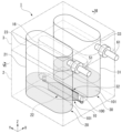
- FIG. 5 is a perspective view showing the cell culture device 1 according to the second embodiment.
- FIG. 6 is a sectional view taken along the line VI-VI shown in FIG.
- FIG. 7 is a sectional view taken along arrow VII-VII shown in FIG.
- the second embodiment differs from the above embodiment in that a lid 3 to which pneumatic pipes 51 and 61 are connected is fixed to the top of the culture container 2.
- the lower surface of the lid 3 has a first concave portion 23 that is concave upward and communicates with the first culture solution storage tank 21, and a first concave portion 23 that is concave toward the top and communicates with the second culture solution storage tank 31.
- a second recess 33 having a concave shape is formed. Note that the upper part of the hydrogel storage tank 16 is closed by the lower surface of the lid part 3.
- a pneumatic pipe 51 is connected to the lid 3 so as to communicate with the first recess 23 .
- a pneumatic pipe 61 is connected to the lid 3 so as to communicate with the second recess 33 .
- the direction in which the pneumatic pipes 51 and 61 are connected to the lid portion 3 is not limited to the Y-axis direction, but may be the X-axis direction or the Z-axis direction.
- the pneumatic pipe 51 is connected to the pneumatic pump 50. Further, the pneumatic pipe 61 is connected to the pneumatic pump 60. Thereby, the first culture solution storage tank 21 can be pressurized from the pneumatic pump 50 via the pneumatic piping 51. Further, the second culture solution storage tank 31 can be pressurized from the pneumatic pump 60 via the pneumatic piping 61. It is preferable to provide a filter in a part of the pneumatic piping 51, 61, thereby suppressing foreign matter such as dust from entering the first culture solution storage tank 21 or the second culture solution storage tank 31. It is preferable to use a filter made of a hydrophobic material with a pore diameter of 0.22 [ ⁇ m] or less, for example.
- O-rings may be placed at the opening edges of the first culture solution storage tank 21 and the second culture solution storage tank 31 of the culture container 2 and sandwiched between them and the lid 3. Thereby, pressure leakage from the gap in the lid portion 3 can be suppressed.
- the lid 3 may be fixed to the culture container 2 with bolts or the like so that the O-ring is crushed in the vertical direction. Thereby, the sealing performance between the container body of the culture container 2 and the lid part 3 can be improved.
- the culture container 2 includes the lid 3.
- Pneumatic pipes 51 and 61 are connected to the lid part 3. According to this configuration, by removing the pneumatic pipes 51 and 61 from the lid 3, the connection between the culture container 2 and the pneumatic device 5 can be easily disconnected. As a result, after transporting the pneumatic pipes 51 and 61 from the lid 3 to another location such as a clean bench, the lid 3 can be removed and the hydrogel 100 or culture solution 101 can be easily transferred to the culture container 2. can be supplied. Further, the pneumatic pipes 51 and 61 are provided with filters. According to this configuration, when applying air pressure, it is possible to suppress foreign matter such as dust from entering the first culture solution storage tank 21 or the second culture solution storage tank 31.
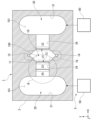
- FIG. 8 is a perspective view showing the cell culture device 1 according to the third embodiment.
- FIG. 9 is a plan cross-sectional view showing the main parts of the cell culture device 1 according to the third embodiment. Note that, like FIGS. 3 and 7 described above, FIG. 9 shows a plan cross-sectional view taken along the hydrogel chamber 10.
- the first culture solution storage section 20 includes the first microchannel 24 that communicates the first culture solution storage tank 21 and the hydrogel chamber 10.
- the second culture solution storage section 30 includes a second microchannel 34 that communicates the second culture solution storage tank 31 and the hydrogel chamber 10.
- the first microchannel 24 includes a flat internal space similarly to the hydrogel chamber 10, and extends in a strip shape in the X-axis direction. Note that the height (dimension in the Z-axis direction) of the internal space of the first microchannel 24 is, for example, the same as that of the hydrogel chamber 10. Further, as shown in FIG. 9, the width (dimension in the Y-axis direction) of the first microchannel 24 is, for example, the same as the width (dimension in the Y-axis direction) of the first surface 12.
- the second microchannel 34 includes a flat internal space similarly to the hydrogel chamber 10, and extends in a strip shape in the X-axis direction.
- the height (dimension in the Z-axis direction) of the internal space of the second microchannel 34 is, for example, the same as that of the hydrogel chamber 10.
- the width of the second microchannel 34 (dimension in the Y-axis direction) is, for example, the same as the width (dimension in the Y-axis direction) of the second surface 13.
- the dimensions of the first microchannel 24 and the second microchannel 34 are not limited to the above dimensions.
- the first microchannel 24 can connect the hydrogel chamber 10 and the first culture solution storage tank 21.
- a space can be secured between the first culture solution storage tank 21 and the hydrogel chamber 10. Therefore, the design space of the culture container 2 for connecting to the pneumatic device 5, the design space of the culture container 2 for widening the opening for introducing the hydrogel 100 into the hydrogel storage tank 16 of the hydrogel chamber 10, etc. This improves the degree of freedom in design.
- the design space of the culture container 2 can be further secured. It becomes easier.
- the first culture solution storage section 20 and the second culture solution storage section 30 may not include a microchannel.
- FIG. 10 is a plan cross-sectional view showing the main parts of the cell culture device 1 according to the fourth embodiment.
- FIG. 11 is an enlarged view of region B shown in FIG. Note that, like FIGS. 3, 7, and 9 described above, FIG. 10 shows a plan cross-sectional view taken along the hydrogel chamber 10.
- the fourth embodiment differs from the above embodiments in that the first microchannel 24 includes a resistance channel 25. Note that the resistance flow path 25 may be provided in the second micro flow path 34.
- the cross-sectional area of the vascular tissue increases as the vascular tissue matures, and the flow rate of the culture solution 101 increases.
- it is difficult to predict changes in the cross-sectional area of vascular tissue and it is also difficult to predict the flow rate of the culture solution 101. Therefore, for example, by pressurizing the first culture solution storage tank 21 (second culture solution storage tank 31), the culture solution 101 stored in the first culture solution storage section 20 (second culture solution storage section 30) can be hydrolyzed.
- a resistance flow path 25 having a small cross-sectional area is provided in a part of the first micro flow path 24.
- the first microchannel 24 is provided with a plurality of resistance channels 25 in parallel, each having a smaller cross-sectional area than the first microchannel 24.
- a plurality of resistance flow paths 25 in parallel as shown in FIG. 11, and preferably 10 or more resistance flow paths 25 are provided in parallel. It would be good if it was set up in Note that the number of resistance channels 25 may be one (one) as long as there is no concern about clogging due to air bubbles or dust.
- the flow path resistance of the resistance flow path 25 is determined by the viscosity ( ⁇ ) of the culture solution 101, the length of the flow path (L MC ), the cross-sectional diameter (d MC ) of the flow path, and the It is defined as the following formula (1) in relation to the number of flow paths (N MC ).
- R MC 8 ⁇ L MC / ⁇ d MC 4 N MC ...(1)
- d MC indicates the diameter when the channel cross section is circular, but when the channel cross section is non-circular, it can be substituted with the equivalent diameter.
- the flow path resistance (R V ) of the blood vessels formed in the hydrogel 100 is determined by the viscosity of the culture medium 101 ( ⁇ ), the length of the blood vessels (L V ), the cross-sectional diameter of the blood vessels (d V ), the parallel It can be estimated from the number of blood vessels (N V ) formed in the following equation (3).
- R V 8 ⁇ L V / ⁇ d V 4 N V ...(3)
- the diameter and number of blood vessels formed in the hydrogel 100 vary depending on the shape of the hydrogel chamber 10 and change with maturation, but the length ( LV ) of the blood vessels in the direction of blood vessel extension of the hydrogel chamber 10
- the length (dimension in the X-axis direction), the cross-sectional diameter (d V ) of the blood vessel is the height (dimension in the Z-axis direction) of the hydrogel chamber 10
- the number of blood vessels formed in parallel (N V ) is the diameter of the hydrogel chamber 10.
- 10 width dimension in the Y-axis direction of the first surface 12 or second surface 13
- the cross-sectional diameter ( dV ) of the blood vessel is calculated.
- Channel resistance can be estimated.
- the flow rate of the culture solution 101 can also be estimated as described later.
- the flow path resistance (R V ) of the blood vessels is approximately 2 ⁇ 10 ⁇ 10 [Pa ⁇ s/ ⁇ m 3 ].
- the resistance channel 25 by setting the resistance channel 25 to have a channel resistance of 2 ⁇ 10 ⁇ 10 [Pa ⁇ s/ ⁇ m 3 ] or more, it can function as a channel resistance that can be used practically as the culture container 2.
- the flow path resistance (R MC ) of the resistance flow channels 25 is 2 ⁇ 10 -10 [Pa ⁇ s/ ⁇ m 3 ].
- the width and depth of the flow path may be set to values smaller than this, or the length of the flow path may be set to smaller values.
- the value may be larger than this, or the number of resistance channels 25 may be reduced by adjusting the gap w4 between the resistance channels 25 as shown in FIG. 11.
- the flow path resistance (R MC ) of the resistance flow path is determined by the viscosity ( ⁇ ) of the culture solution, the length (L) from the first surface 12 to the second surface 13 of the hydrogel chamber 10, and the length (L) of the hydrogel chamber 10.
- the height (d) is a value obtained by dividing the width of the first surface 12 or the second surface 13 by the height of the hydrogel chamber 10 as (N)
- N is preferably a natural number.
- the maximum flow rate of the culture solution 101 can be estimated in this way, the minimum period of replenishment frequency of the culture solution 101 can be estimated, and the work of performing perfusion culture over a long period of time can be made more efficient.
- the first microchannel 24 is provided with the resistance channel 25 having a smaller cross-sectional area than the first microchannel 24 .
- the flow path resistance (R MC ) of the resistance flow path 25 depends on the viscosity ( ⁇ ) of the culture solution, the length (L) from the first surface 12 to the second surface 13 of the hydrogel chamber 10, and the height of the hydrogel chamber 10. (d), when the value obtained by dividing the width of the first surface 12 or the second surface 13 by the height of the hydrogel chamber 10 is (N), the relationship of the above formula (5) is satisfied.
- the increase in the flow rate of the culture solution 101 can be controlled and the maximum flow rate of the culture solution 101 can be estimated.
- the work of performing perfusion culture can be made more efficient.
- FIG. 12 is a perspective view showing the cell culture device 1 according to the fifth embodiment.
- FIG. 13 is a sectional view taken along arrows XIII-XIII shown in FIG.
- FIG. 14 is a sectional view taken along arrows XIV-XIV shown in FIG. 13.
- the fifth embodiment differs from the above embodiments in that a third culture solution reservoir 80 is provided directly above the hydrogel chamber 10.
- the third culture solution storage section 80 includes a third culture solution storage tank 81 that stores the culture solution 101.
- the third culture solution storage tank 81 in the example shown in the figure also serves as the hydrogel storage tank 16 for introducing the hydrogel 100 into the hydrogel chamber 10.
- the third culture solution storage tank 81 is formed in a long hole shape or an elliptical shape extending in the Y-axis direction when viewed from above. Note that the shape of the third culture solution storage tank 81 in plan view is not particularly limited.
- the third culture solution storage tank 81 preferably has a larger internal space (volume) than the hydrogel chamber 10.
- one large opening 82 communicating with the top surface of the hydrogel chamber 10 is formed in the center of the bottom surface of the third culture solution storage tank 81.
- a permeable membrane 82a may be provided in the opening 82.
- the permeable membrane 82a has one side facing the hydrogel 100 and the other side facing the culture solution 101.
- the permeable membrane 82a is preferably one that cannot be penetrated by the hydrogel 100 but can be penetrated by the culture solution 101, for example. Further, the permeable membrane 82a may be attached to the opening 82 in a removable structure.
- the pneumatic device 5 includes a pneumatic pump 90 connected to the third culture solution storage tank 81.
- the upper part of the third culture solution storage tank 81 is closed by the lid part 3.
- a third recess 83 that is concave upward and communicates with the third culture solution storage tank 81 is formed on the lower surface of the lid 3 .
- a pneumatic pipe 91 is connected to the lid 3 so as to communicate with the third recess 83.
- Pneumatic piping 91 is connected to pneumatic pump 90 . Thereby, the third culture solution storage tank 81 can be pressurized from the pneumatic pump 90 via the pneumatic piping 91.
- the opening 82 is formed directly above the hydrogel chamber 10.
- organoids which are cell aggregates
- perfuse culture solution 101 through the microvessels.
- FIGS. 13 and 14 by providing one large opening 82 directly above the hydrogel chamber 10, introduction of the hydrogel 100 is facilitated.
- the cell aggregate can be placed on the hydrogel 100 using the opening 82, and the culture solution 101 can be perfused into the cell aggregate via the microvascular network.
- a permeable membrane 82a can be provided in the opening 82, with one surface facing the hydrogel 100 and the other surface facing the culture solution 101.
- the permeation rate of drug candidate compounds through microvessels such as the blood-brain barrier may be evaluated.
- a permeable membrane 82a is provided in the opening 82 provided directly above the hydrogel chamber 10, so that one surface of the permeable membrane 82a is exposed to the hydrogel 100.
- the third culture solution storage tank 81 that holds the culture solution 101, compounds exposed in the hydrogel 100 can be collected through the permeable membrane 82a. It becomes possible to analyze.
- the opening 82 is provided directly above the hydrogel chamber 10 as in the fifth embodiment, at least one of the first culture solution storage section 20 and the second culture solution storage section 30 is pressurized to increase the culture solution 101.
- the culture solution 101 may leak from the opening 82 of the hydrogel chamber 10.
- the pneumatic device 5 is connected to the third culture fluid storage section 80.
- the hydrogel chamber 10 can be directly It is possible to prevent the culture solution 101 from leaking from the upper opening 82.
- FIG. 15 is a perspective view showing a cell culture device 1 according to the sixth embodiment.
- FIG. 16 is a sectional view taken along arrows XVI-XVI shown in FIG.
- FIG. 17 is a sectional view taken along arrow XVII-XVII shown in FIG. 16.
- the sixth embodiment differs from the above embodiment in that hydrogel storage tanks 16A and 16B are provided separately from the third culture solution storage tank 81.
- the hydrogel storage tanks 16A and 16B are provided as a pair with the third culture solution storage tank 81 sandwiched therebetween in the Y-axis direction. Hydrogel storage tanks 16A and 16B are circular in plan view. Note that the shape of the hydrogel storage tanks 16A and 16B in plan view is not particularly limited. The hydrogel storage tanks 16A and 16B preferably have a smaller internal space (volume) than the third culture solution storage tank 81, for example, from the viewpoint of installation space.
- the bottom surface of the hydrogel storage tank 16A communicates with the hydrogel chamber 10 via the introduction hole 14. Further, the bottom surface of the hydrogel storage tank 16B communicates with the hydrogel chamber 10 via the introduction hole 15. As shown in FIG. 17, the hydrogel storage tanks 16A and 16B communicate with the hydrogel chamber 10 through introduction holes 14 and 15 that are sufficiently smaller than the opening 82, and the culture solution from the hydrogel chamber 10 is communicated with the hydrogel storage tanks 16A and 16B. 101 is not connected to the pneumatic device 5 like the third culture solution storage tank 81 because there is little problem of leakage, but even if it is connected to the pneumatic device 5 like the third culture solution storage tank 81. I do not care.
- the introduction holes 14 and 15 for introducing the hydrogel 100 into the hydrogel chamber 10 are arranged at a different position from the opening 82 directly above the hydrogel chamber 10. For example, it becomes easier to collect and analyze the compounds exposed in the hydrogel 100 through the permeable membrane 82a.
- FIG. 18 is a schematic plan view showing the cell culture device 1 according to the seventh embodiment. As shown in FIG. 18, the seventh embodiment differs from the above embodiments in that a pair of first microchannels 24 and a pair of second microchannels 34 are provided.
- the first microchannel 24 includes a pair of microchannels 24A and 24B. That is, the first culture solution storage tank 21 and the hydrogel chamber 10 are connected by two microchannels 24A and 24B.
- the first microchannel 24 is formed in a C-shape or a U-shape when viewed from above.
- the first microchannel 24 communicates with the first culture solution storage tank 21 at both C-shaped or U-shaped ends, and connects to the first surface 12 of the hydrogel chamber 10 at a location other than both ends (middle portion). It's communicating.
- the second microchannel 34 includes a pair of microchannels 34A and 34B. That is, the second culture solution storage tank 31 and the hydrogel chamber 10 are connected by two microchannels 34A and 34B.
- the second microchannel 34 is formed in a C-shape or a U-shape when viewed from above.
- the second microchannel 34 communicates with the second culture solution storage tank 31 at both ends of the C-shape or U-shape, and connects to the second surface 13 of the hydrogel chamber 10 at a location other than both ends (middle portion). It's communicating.
- the first microchannel 24 and the second microchannel 34 are each provided in pairs.
- the first microchannel 24 by introducing the culture solution 101 from the first culture solution storage tank 21 into either one of the microchannels 24A, 24B, air bubbles in the first microchannel 24 can be easily removed. Can be removed.
- the second microchannel 34 by introducing the culture solution 101 from the second culture solution storage tank 31 into either one of the microchannels 34A, 34B, air bubbles in the second microchannel 34 are generated. can be easily removed.
- FIG. 19 is a schematic plan view showing the cell culture device 1 according to the eighth embodiment. As shown in FIG. 19, the eighth embodiment differs from the above embodiments in that a return flow path 110 that communicates the first culture solution storage tank 21 and the second culture solution storage tank 31 is provided.
- the white arrows in FIG. 19 indicate the flow of the culture solution 101. That is, in the example shown in FIG. 19, the culture solution 101 is supplied from the first culture solution storage tank 21 to the hydrogel chamber 10 via the first microchannel 24, and from the hydrogel chamber 10 to the second microchannel 34. It flows out into the second culture solution storage tank 31 via the second culture solution storage tank 31 and returns to the first culture solution storage tank 21 via the return channel 110.
- a passive valve 111 is provided in the return channel 110 as a mechanism for preventing backflow of the culture solution 101 from the first culture solution storage tank 21 to the second culture solution storage tank 31.
- the passive valve 111 is, for example, It has minute fluid channels, and by adjusting the cross-sectional area, shape, length, wettability, etc. of the fluid channels, the culture solution 101 is transferred to the second culture while preventing air bubbles from entering from the first culture solution storage tank 21.
- the liquid can flow in one direction from the liquid storage tank 31 to the first culture liquid storage tank 21.
- the pressure resistance of the passive valve 111 is preferably within the range of 0.1 [kPa] to 10 [kPa]. This makes it possible to perform culture operations within a physiological range within which the culture container 2 can be controlled by a commercially available pressure regulator.
- the pressure resistance ( ⁇ P Lap ) of the passive valve 111 can be estimated using the interfacial tension ( ⁇ ) and the flow path cross-sectional diameter (d) as shown in the following equation (8).
- ⁇ P Lap 4 ⁇ /d...(8)
- check valves 36 are provided at both ends of the second microchannel 34 on the second culture solution storage tank 31 side as a mechanism for preventing backflow of the culture solution 101. Thereby, when pressurizing the second culture solution storage tank 31 and returning the culture solution 101 to the first culture solution storage tank 21, it is possible to prevent the culture solution 101 from flowing back toward the hydrogel chamber 10 side. .
- the pneumatic device 5 switches between supplying the culture solution 101 and returning the culture solution 101 at predetermined intervals.
- the supply time of the culture solution 101 is preferably set longer than the return time of the culture solution 101.
- the pneumatic device 5 pressurizes the first culture solution storage tank 21, and supplies the culture solution 101 to the hydrogel chamber 10 by the pressure difference between the first culture solution storage tank 21 and the second culture solution storage tank 31.
- the pneumatic device 5 pressurizes the second culture solution storage tank 31 in which the culture solution has accumulated, and uses the differential pressure with the first culture solution storage tank 21 to send the culture solution through the return channel 110.
- the culture solution 101 is returned to the first culture solution storage tank 21.
- the end of the return flow path 110 on the first culture solution storage tank 21 side is preferably higher than the end of the return flow path 110 on the second culture solution storage tank 31 side. Thereby, backflow of the culture solution 101 from the first culture solution storage tank 21 to the second culture solution storage tank 31 can be suppressed.
- the return channel 110 for the culture solution 101 that communicates the first culture solution storage tank 21 and the second culture solution storage tank 31, the second microchannel 34, and the return channel 110 A mechanism for preventing backflow of the culture solution 101 is provided. According to this configuration, depletion of the culture solution 101 in the first culture solution storage tank 21 can be prevented, and cells can be cultured for a long period of time.
- a passive valve 111 that prevents air bubbles from entering is provided as a mechanism for preventing backflow.
- the introduction of air into the return flow path 110 can be prevented at the position of the passive valve 111, and the air introduced into the return flow path 110 can be prevented from being introduced into the return flow path 110. This makes it possible to prevent air bubbles from being generated in the first culture solution storage tank 21 and the second culture solution storage tank 31, thereby stabilizing the culture operation.
- the pressure resistance of the passive valve 111 is within the range of 0.1 [kPa] to 10 [kPa]. According to this configuration, culture operations can be performed within a physiological range that can be controlled by a commercially available pressure regulator.
- FIG. 20 is a schematic plan view showing the cell culture device 1 according to the ninth embodiment. As shown in FIG. 20, the ninth embodiment differs from the above embodiments in that a resistance channel 35 is provided in each of the pair of microchannels 34A, 34B of the second microchannel 34.
- the resistance flow path 35 provided in the second micro flow path 34 has the same configuration as the resistance flow path 25 provided in the first micro flow path 24 shown in FIG. 11 described above. That is, the second microchannel 34 is provided with one or a plurality of resistance channels 35 having a smaller cross-sectional area than the second microchannel 34 in parallel.
- the flow path resistance (R MC ) of the resistance flow path 35 is determined by the viscosity ( ⁇ ) of the culture solution, the length (L) from the first surface 12 to the second surface 13 of the hydrogel chamber 10, and the hydrogel chamber 10.
- the value obtained by dividing the height (d) of the first surface 12 or the second surface 13 by the height of the hydrogel chamber 10 is (N)
- the relationship R MC ⁇ 8 ⁇ L/ ⁇ d 4 N is satisfied. It's good to do that.
- the increase in the flow rate of the culture solution 101 can be controlled and the maximum flow rate of the culture solution 101 can be estimated.
- the work of performing perfusion culture can be made more efficient.
- the flow path resistance of the passive valve 111 to be greater than the flow path resistance of the blood vessel, it can also serve as the resistance flow path 35 .
- a channel for blood vessel formation (hydrogel chamber 10, etc.) of the culture container 2 shown in FIGS. 19 and 20 was fabricated by photolithography and PDMS (polydimethylsiloxane) molding.
- the size of the hydrogel chamber 10 is 5.6 [mm] in the length direction (X-axis direction) of the blood vessel, 9.7 [mm] in the width (Y-axis direction), and 9.7 [mm] in the depth (Z-axis direction). direction dimension) is 0.3 [mm].
- FIG. 21 is a graph showing the relationship between blood vessel diameter, shear stress, and flow rate according to the first example. Note that FIG. 21 shows the results of estimating the relationship between the blood vessel diameter, shear stress, and flow rate using equation (6).
- no resistance flow path indicates the calculation result when vascular tissue is formed in the culture vessel 2 without the resistance flow path 35 shown in FIG.
- with resistance flow path indicates the calculation result when vascular tissue is formed in the culture vessel 2 with the resistance flow path 35 shown in FIG.
- the inside of the culture container 2 is pressurized at 1 [kPa]
- the flow path resistance (R MC ) of the resistance channel 25 is set to 2 ⁇ 10 ⁇ 8 [Pa ⁇ s/ ⁇ m 3 ]
- the culture medium 101 The viscosity ( ⁇ ) was 0.001 [Pa ⁇ s]
- the length of the blood vessels formed (L V ) was 5600 [ ⁇ m]
- the number of blood vessels formed in parallel (N V ) was 16.
- the calculation results for the case are shown below. It can be seen that in the culture vessel 2 with "no resistance flow path", the flow rate of the culture solution 101 increases as the blood vessel diameter increases. On the other hand, it can be seen that in the culture vessel 2 with "resistance flow path", the flow rate of the culture solution does not rise above 230 [ ⁇ L/min] even if the blood vessel diameter increases.
- poly-L-lysine hydrobromide (molecular weight 30,000 to 70,000: SIGMA- (manufactured by ALDRICH) was injected and allowed to stand at 37 [°C] for 1 hour, and then washed twice with phosphate buffered saline.
- fibrinogen derived from human plasma (manufactured by Wako) was diluted with D-PBS (-) (manufactured by Wako) to a concentration of 6 [mg/ml] at 37 [°C]. ] and filter sterilized using a 0.22 filter Milliex-GV (manufactured by Millipore) and a Terumo syringe (manufactured by TERMO).
- cultured human vascular endothelial cells HUVEC were fluorescently stained with CellTracker TM Red CMTPX Dye (manufactured by Invitrogen). Thereafter, the cells were detached by trypsin treatment, centrifuged, resuspended in a resuspension buffer (a cell suspension containing Thrombin at a final concentration of 4 [U/mL]), and the cell concentration was counted. The mixture was diluted again with a resuspension buffer so that the cell concentration was 12 ⁇ 10 6 [cells/mL].
- a resuspension buffer a cell suspension containing Thrombin at a final concentration of 4 [U/mL]
- the culture containers 2 shown in FIGS. 19 and 20 were pre-chilled to 4°C, and a pre-gel solution was prepared by mixing a fibrinogen solution and a cell research suspension containing HUVEC at a ratio of 1:1.
- the pre-gel solution was injected into the hydrogel chamber 10 of. Then, the gel was placed in a 5% CO 2 incubator at 37 [°C] and kept warm for 15 minutes to solidify the gel, and then a special medium EGM TM BulletKit TM EGM TM Endothelial Cell Growth Medium BulletKit TM (manufactured by Lonza) was placed in the medium channel.
- a check valve 36 was attached to the opening of the second microchannel 34 located in the second culture solution storage tank 31.
- the first culture solution storage tank 21 is pressurized at 1 [kPa] for 240 [sec] to sequentially feed the medium to the cells
- the second culture solution storage tank 31 is pressurized at 1 [kPa] for 60 [sec]. The cycle of pressurizing and returning was repeated for 7 days.
- the day the cells were introduced was defined as day 0, and fluorescence microscopic observation and progressive flow rate measurements were performed on days 3 to 7. Medium exchange was performed on the 3rd and 6th day. Every day from the 4th to the 7th day, 10 [ ⁇ l] of 70 kDa FITC dextran (manufactured by SIGMA) was flowed for 5 minutes using hydrostatic pressure, and then observed under a fluorescence microscope to analyze the shape and conduction of the blood vessels.
- FIG. 22 is a fluorescence microscope image of vascular tissue in the case of "no resistance flow path” according to the first example.
- FIG. 23 is a fluorescence microscope image of vascular tissue in the case of "with resistance flow path” according to the first example.
- FIGS. 22 and 23 show fluorescence microscope images observed on day 0, day 3, day 5, and day 7 of the above results.
- blood vessels were elongating and expanding, and cells were also oriented along the flow of the medium.
- the expansion of the blood vessels had further progressed, and a stronger orientation of the cells was observed than on the 3rd day.
- HUVECs proliferated to such an extent that gel areas between blood vessels could hardly be observed, and cell orientation was also lost.
- FIG. 24 is a fluorescence microscope image of the entire vascular tissue in the case of "no resistance flow path" according to the first example.
- FIG. 25 is a fluorescence microscope image of the entire vascular tissue in the case of "with resistance flow path” according to the first example.
- 24 and 25 show the results of observing the state of the entire blood vessel after flowing 70 kDa FITC dextran for 3 days after blood vessel conduction. As shown in FIG. 24, the blood vessels became conductive on the 5th day with “no resistance flow path" and on the 4th day with “resistance flow path". Over the next three days, the blood vessels in both channels expanded, and no difference was observed in the speed of expansion.
- FIG. 26 is a graph showing the relationship between the sequential flow rate of the culture solution 101 and the culture period according to the first example.
- the blood vessels were slightly conductive on the fourth day, and the flow rate was 81.8 [ ⁇ l/min]. Thereafter, the flow rate rapidly increased as the blood vessels expanded, reaching 330.2 [ ⁇ l/min] on the 5th day and 839.2 [ ⁇ l/min] on the 7th day.
- the blood vessel became conductive on the 4th day, and the flow rate was 288.5 [ ⁇ l/min].
- vascular tissue with a length of 2 [mm] or less have been reported, but there have been no reports of constructing vascular tissues larger than this.
- a vascular tissue up to a length of 5.6 [mm] could be constructed by applying the present invention.
- larger vascular tissue can be used to conduct compound permeability testing using vascular tissue that has a larger surface area.
- the use of vascular tissue having a larger surface area has the advantage of increasing the amount of compound that has permeated through the vascular wall and improving the sensitivity of the permeability test.
- the present invention by forming microvascular tissue while continuing to apply air pressure, it has become possible to perfuse the culture solution 101 in accordance with the formation of microvascular tissue.
- the perfusion flow rate of the culture solution 101 can be reported over time, and the microvascular tissue can be stably maintained over a long period of time.
- Such perfusion that corresponds to the formation of microvascular tissue and the construction of stable vascular tissue over a long period of time can increase the stability of compound permeability tests, and can also be applied to organoid culture combined with vascular tissue. This allows the formation of more mature organoids.
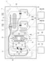
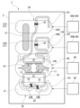
- FIG. 27 is a schematic plan view showing the cell culture device 1 according to the second example.
- a cell culture apparatus 1 shown in FIG. 27 was used.
- This cell culture device 1 is characterized in that the second culture solution storage tank 31 of the second culture solution storage section 30 is divided into second culture solution storage tanks 31A and 31B, and that the first microchannel 24 has a resistance flow.
- This embodiment differs from the configuration shown in FIG. 20 (first embodiment) in that a path 25 is provided.
- the pneumatic pump 60 includes a pneumatic pump 60A connected to the second culture solution storage tank 31A, and a pneumatic pump 60B connected to the second culture solution storage tank 31B.
- a pneumatic pump 50 is connected to the first culture solution storage tank 21 .
- a pneumatic pump 90 is connected to the third culture solution storage tank 81 .
- the second culture solution storage tanks 31A and 31B communicate with each other through a communication channel 37.
- the communication channel 37 balances the liquid level of the culture solution 101 in the second culture solution storage tanks 31A and 31B.
- the return channel 110 is connected between the second culture solution storage tank 31A and the first culture solution storage tank 21, but is connected between the second culture solution storage tank 31B and the first culture solution storage tank 21. May be connected.
- the resistance channel 25 is provided in each of the microchannels 24A and 24B of the first microchannel 24.
- each channel for blood vessel formation in the culture container 2 was fabricated by photolithography and PDMS (polydimethylsiloxane) molding.
- the size of the hydrogel chamber 10 is 5.6 [mm] in the length direction (X-axis direction) of the blood vessel, 9.7 [mm] in the width (Y-axis direction), and 9.7 [mm] in the depth (Z-axis direction). direction dimension) is 0.3 [mm].
- the resistance channel 25 of the first micro channel 24 and the resistance channel 35 of the second micro channel 34 have a length of 1.2 [mm], a width of 0.08 [mm], and a height of 0.06 [mm]. mm].
- the pressure resistance of the first microchannel 24 and the second microchannel 34 is estimated to be 3.5 [kPa] from equation (8).
- Resistance flow path 25 also functions as a passive valve.
- the culture container 2 shown in FIG. 27 has a resistance flow path 25 provided in the first micro flow path 24, compared to the culture container 2 shown in FIGS. 19 and 20. Further, the opening of the second microchannel 34 is approximately 1 cm higher than the bottom surface of the second culture solution storage tank 31A, 31B. The opening of the first microchannel 24 is provided on the bottom surface of the first culture solution storage tank 21. With this configuration, the flow of the culture solution can be restricted only in the direction from the first culture solution storage tank 21 to the second culture solution storage tanks 31A, 31B (in the direction of the arrow in the figure), and backflow can be prevented.
- the culture solution in the first culture solution storage tank 21 is transferred to the opening of the first microchannel 24, the first microchannel 24 , the hydrogel chamber 10 , and the second microchannel 34 to the opening of the second microchannel 34 .
- the opening of the second microchannel 34 is higher than the liquid level of the culture solution in the second culture solution storage tanks 31A and 31B. Air flows into the second microchannel 34 from the opening of the second microchannel 34, and the resistance channel 35 acts as a passive valve, stopping the inflow of air and also stopping the flow of the culture solution. Therefore, by alternately pressurizing the pneumatic pump 50 and the pneumatic pump 60 (60A, 60B), a one-way flow from the opening of the first microchannel 24 to the opening of the second microchannel 34 is generated. can be caused.
- the dimensions of the passive valve 111 of the return flow path 110 are 0.24 [mm] in length, 0.08 [mm] in width, and 0.06 [mm] in height.
- the pressure resistance of the passive valve is estimated to be 3.5 [kPa] from equation (8).
- the opening on the first culture solution storage tank 21 side of the return flow path 110 is approximately 1 cm higher than the bottom surface of the first culture solution storage tank 21, and the opening on the second culture solution storage tank 31A side of the return flow path 110 is higher than the bottom surface of the first culture solution storage tank 21.
- the section is provided on the bottom surface of the second culture solution storage tank 31A.
- the culture solution 101 in the second culture solution storage tank 31A is transferred to the second culture solution storage tank in the return channel 110. It flows through the opening on the 31A side and the return flow path 110 to the opening of the return flow path 110 on the first culture solution storage tank 21 side.
- the opening of the return channel 110 on the first culture solution storage tank 21 side is higher than the liquid level of the culture solution in the first culture solution storage tank 21.
- poly-L-lysine hydrobromide (molecular weight 30,000 to 70,000; SIGMA-ALDRICH Co., Ltd. (manufactured by Nippon Steel & Co., Ltd.) was injected and allowed to stand at 37 [°C] for 1 hour, and then washed with a sterilized 50% ethanol aqueous solution three times or more, and then completely dried.
- the following test was conducted using the cell culture device 1 shown in FIG. 27 in order to confirm how the medium components permeated into the hydrogel 100 by pressurized perfusion.
- fibrinogen derived from bovine plasma (manufactured by Wako)
- D-PBS D-PBS
- Wako D-PBS
- the mixture was dissolved and filter sterilized using a 0.22 filter Milliex-GV (manufactured by Millipore) and a Terumo syringe (manufactured by TERMO).
- a culture solution (EGM-2MV, manufactured by Lonza) containing 4 [U/mL] of Thrombin (manufactured by Wako) was prepared.
- the culture container 2 was previously cooled to 4 [° C.], a pre-gel solution was prepared by mixing a fibrinogen solution and a culture solution containing Thrombin at a ratio of 1:1, and the pre-gel solution was injected into the hydrogel chamber 10 of the culture container 2. . Then, after placing the gel in a 37 [°C], 5% CO 2 incubator and keeping it warm for 35 minutes to solidify the gel, the culture solution EGM-2MV was introduced through the openings of the second microchannel 34 and the first microchannel 24. The cells were introduced into a 37 [° C.], 5% CO 2 incubator and kept warm for 60 minutes. The culture solution was introduced into the return flow path 110 from the opening on the first culture solution storage tank 21 side of the return flow path 110 .
- pressurized perfusion was started under the following conditions. Pressurized perfusion was performed in an incubator at 37° C. and 5% CO 2 .
- the first culture solution storage tank 21 and the third culture solution storage tank 81 were pressurized at 0.5 kPa for 1440 seconds to feed the culture medium sequentially, and the second culture solution storage tanks 31A and 31B were pressurized for 360 seconds. The cycle of returning the culture solution 101 was repeated.
- 500 [ ⁇ L] of the culture solution 101 was further added to the first culture solution storage tank 21.
- pressurization of the first culture solution storage tank 21 is started at 0.5 [kPa], 1.0 [kPa], 2.0 [kPa], and 3.0 [kPa], and the fluorescence Microscopic images were taken.
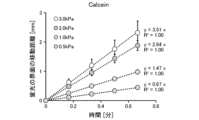
- FIG. 28 is a fluorescence microscope image of Calcein immediately after and 50 seconds after pressurizing the culture container 2 according to the second example at 2.0 [kPa]. As shown in FIG. 28, the Calcein fluorescence interface for 50 seconds moves upward by about 2.0 to 2.5 [mm] compared to immediately after pressurization.
- FIG. 29 shows the Rhodamine- It is a graph showing the results of measuring the movement of the interface of Dextran fluorescence over time.
- FIG. 30 shows Calcein when the culture container 2 according to the second example was pressurized at 0.5 [kPa], 1.0 [kPa], 2.0 [kPa], and 3.0 [kPa]. It is a graph showing the results of measuring the movement of the fluorescent interface at each time. As shown in FIGS. 29 and 30, the interfacial movement speeds of the fluorescence of Calcein and Rhodamine-Dextran were similar, and it was observed that the interfacial movement speed of the fluorescence became faster in proportion to the pressure.
- HUVECs were fluorescently stained with CellTracker TM Red CMTPX Dye (manufactured by Invitrogen). Thereafter, HUVECs and mesenchymal stem cells (UE7T-13, JCRB Cell Bank) were detached with 0.05% or 0.25% Trypsin-EDTA at 12 ⁇ 106 [cells/mL] and 4 ⁇ 106 [cells/mL], respectively. /mL] was suspended in EGM-2MV to which 4 [U/mL] of Thrombin (manufactured by FUJIFILM Wako Pure Chemical Corporation) was added.
- the culture vessels 2 shown in FIG. 27 are pre-chilled to 4 [°C], and a pre-gel solution is prepared by mixing a fibrinogen solution and a Cytochemistry suspension containing HUVEC and MSCs at a ratio of 1:1.
- a pregel solution was injected into the hydrogel chamber 10.
- the culture solution EGM-2MV was placed in a 5% CO 2 incubator at 37 [°C] and kept warm for 35 minutes to solidify the gel.
- the cells were introduced into a 37 [° C.], 5% CO 2 incubator and kept warm for 60 minutes.
- the culture solution 101 was introduced into the return channel 110 through the opening on the first culture solution storage tank 21 side of the return channel 110 .
- pressurized perfusion was started under the following conditions.
- Pressurized perfusion was performed in an incubator at 37°C and 5% CO2 .
- the first culture solution storage tank 21 and the third culture solution storage tank 81 are pressurized at 2.0 [kPa] for 360 seconds, and the second culture solution storage tanks 31A and 31B are pressurized for 90 seconds.
- the cycle of pressing and returning was repeated for 12 days.
- the day on which the cells were introduced was defined as day 0, and fluorescence microscopic observation and progressive flow rate measurements were performed on days 1 to 12.
- the medium was replaced every time the flow rate was measured.
- FIG. 31 is a fluorescence microscope image showing the formation behavior of blood vessels with and without mesenchymal stem cells according to the second example.
- FIG. 32 is a graph showing changes in blood vessel flow rate when mesenchymal stem cells are included and when they are not included according to the second example. As shown in FIG. 31, the formation of microvasculature was confirmed on day 4 regardless of the presence or absence of mesenchymal stem cells. During this time, an increase in the flow rate of the culture solution 101 was confirmed with the formation of vascular tissue (see FIG. 32).
- the culture container 2 shown in FIG. 27 has a backflow prevention mechanism that controls the flow direction of the culture solution 101 and a return channel 110.
- the culture solution is configured to flow in one direction toward the culture solution storage tanks 31A and 31B.
- a culture vessel shown in FIG. 33 was prepared.
- FIG. 33 is a schematic plan view showing a cell culture device 1 according to a modified example of the second embodiment.
- the culture container 2 shown in FIG. 33 does not have a return flow path 110.
- the opening of the second microchannel 34 is provided on the bottom surface of the second culture solution storage tank 31A, 31B.
- vascular tissue In the formation of vascular tissue, the formation behavior of vascular tissue was compared and studied under the environment of unidirectional flow and reciprocating flow using the culture container 2 shown in FIG. 27 and the culture container 2 shown in FIG. 33. Similar to the above experiment (conditions of culturing in a system containing mesenchymal stem cells using culture vessel 2 shown in Figure 27), HUVEC and mesenchymal cells were introduced into hydrogel 100, and pressurized perfusion was started. . The conditions for pressurized perfusion are, when producing a unidirectional flow, the first culture solution storage tank 21 and the third culture solution storage tank 81 are pressurized at 2.0 [kPa] for 360 seconds, and the first culture solution storage tank 81 is fed sequentially.
- a cycle of pressurizing the two culture solution storage tanks 31A and 31B for 90 seconds and returning them was repeated for 12 days.
- the first culture solution storage tank 21 and the third culture solution storage tank 81 are pressurized at 2.0 [kPa] for 360 seconds, and then the second culture solution storage tank 31A, 31B A cycle of applying pressure for 360 seconds was repeated for 12 days.
- FIG. 34 is a fluorescence microscope image showing the formation behavior of vascular tissue under the environment of unidirectional flow and reciprocating flow according to the second example and a variation thereof.
- formation of vascular tissue was confirmed from around 4 days after cell introduction.
- FIG. 34 shows images of vascular tissue 6 days after cell introduction. The formation of vascular tissue can be confirmed in both unidirectional flow and reciprocating flow, but it appears that the vascular tissue is oriented in the direction of flow in the unidirectional flow condition compared to the reciprocating flow condition. observed.
- FIG. 35 is a graph showing changes in the flow rate of vascular tissue under the environment of unidirectional flow and reciprocating flow according to the second embodiment and a modification thereof. As shown in Figure 35, in both cases of unidirectional flow and reciprocating flow, an increase in flow rate due to the formation of vascular tissue was observed from day 4 to 6 after cell introduction, and the flow rate increased through the vascular tissue until day 12. The flow of the culture solution 101 was confirmed.
- FIG. 36 is an image analysis diagram when determining the permeability coefficient of the fluorescent substance through the blood vessel wall in order to evaluate the barrier ability of the blood vessel tissue formed with the cell culture device 1 according to the second embodiment and its modification. .
- the permeability coefficient of fluorescent substances through the vascular wall was determined by image analysis. The permeability coefficient of the fluorescent substance was determined by the following method on the 4th day of culture for the system not containing mesenchymal stem cells, and on the 6th day of culture for the system co-cultured with mesenchymal stem cells.
- P [cm/sec] is a transmission coefficient.
- J s [mol/sec] is the amount of substance permeated per unit time.
- a w [cm 2 ] is the area of the blood vessel wall through which the substance permeates.
- C L [mol/cm 3 ] is the concentration difference between the inside and outside of the blood vessel wall.
- ⁇ I ex,mean [ ⁇ ] is the temporal change in the average fluorescence brightness of the region surrounded by blood vessels.
- a i [cm 2 ] is the area of the region surrounded by blood vessels.
- ⁇ t [sec] is the amount of change over time.
- l w [cm] is the circumference of a region surrounded by blood vessels.
- I i,mean [-] is the average fluorescence intensity on the blood vessel side near the area surrounded by the blood vessels.
- I b,mean [-] is the average fluorescence intensity of the area surrounded by blood vessels.
- ImageJ (1.53c, manufactured by NIH) was used to analyze the image data.
- FIG. 37 shows (i) no mesenchymal stem cells, unidirectional flow, (ii) unidirectional flow, with mesenchymal stem cells, and (iii) with mesenchymal stem cells, according to the second embodiment and a variation thereof.
- the permeability coefficients of Calcein obtained under three conditions of reciprocating flow are shown.
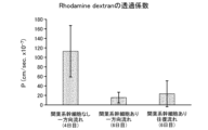
- FIG. 38 shows (i) no mesenchymal stem cells and unidirectional flow, (ii) unidirectional flow with mesenchymal stem cells, and (iii) with mesenchymal stem cells and a modified example thereof.
- the permeability coefficients of Rhodamine-Dextran obtained under three conditions of reciprocating flow are shown.
- the system containing mesenchymal stem cells has a smaller permeability coefficient. Furthermore, it was observed that the permeability coefficient tended to be lower in unidirectional flow than in reciprocating flow. From this result, the culture container 2 having the configuration shown in FIG. 27, which has a backflow prevention mechanism that controls the flow direction of the culture solution 101 and a return flow path 110, is useful for forming vascular tissue with high barrier ability. Something was suggested.
- immunostaining was performed using the following method.
- the vascular tissue formed using only HUVEC was fixed on the 4th day, and the vascular tissue formed by mixing with mesenchymal stem cells was fixed on the 6th day using 4% paraformaldehyde.
- CD31 was labeled with a 200-fold diluted rabbit monoclonal antibody (28364 or 32457: manufactured by ABCAM).
- NG2 was labeled with a 200-fold diluted mouse monoclonal antibody (MAB2585: manufactured by R&D Systems).
- vascular endothelial cadherin (VE-cadherin), laminin, and Invitrogen 33-9100 were labeled with 100-fold diluted rabbit polyclonal antibodies (CST2158S, abcam11575, and Invitrogen 33-9100, respectively).
- Fluorescently labeled secondary antibodies (Invitrogen A11011, A11034 or abcam150113) were used at 200- to 400-fold dilutions.
- Cell nuclei were stained with Cellstain-DAPI solution (manufactured by Dojindo Laboratories) at a dilution of 1:1000.
- F-actin filaments were stained with Phalloidin-iFluor 488 (Cayman Chemical Company) at a 1:1000 dilution.
- FIG. 39 shows an image in which vascular endothelial cells formed in the cell culture device 1 according to the second embodiment and a modification thereof are stained with CD31, which is a marker, and an image in which vascular endothelial cells are stained with NG2, which is a mesenchymal stem cell marker.
- CD31 which is a marker
- NG2 which is a mesenchymal stem cell marker.
- FIG. 39 in a mixed culture system with mesenchymal stem cells, mesenchymal stem cells exist around the vascular tissue formed by vascular endothelial cells under both unidirectional flow and reciprocating flow conditions. This was confirmed.
- FIG. 40 is a diagram showing images of vascular endothelial cells formed in the cell culture device 1 according to the second example and a variation thereof, stained with ZO-1, which constitutes tight junctions in the blood vessel wall.
- ZO-1 As shown in FIG. 41, under the condition of unidirectional flow with mesenchymal stem cells, ZO-1 is expressed throughout the blood vessel wall compared to other conditions. This suggests that the high barrier capacity of blood vessels, that is, the low permeability coefficient, observed in FIG. 36 is achieved by the expression of tight junction molecules.
- the culture container 2 having the configuration shown in FIG. It was shown to be useful in forming vascular tissue with high barrier capacity.
Landscapes
- Engineering & Computer Science (AREA)
- Health & Medical Sciences (AREA)
- Life Sciences & Earth Sciences (AREA)
- Bioinformatics & Cheminformatics (AREA)
- Chemical & Material Sciences (AREA)
- Zoology (AREA)
- Biomedical Technology (AREA)
- Organic Chemistry (AREA)
- Wood Science & Technology (AREA)
- Biotechnology (AREA)
- Genetics & Genomics (AREA)
- General Health & Medical Sciences (AREA)
- Biochemistry (AREA)
- General Engineering & Computer Science (AREA)
- Microbiology (AREA)
- Sustainable Development (AREA)
- Cell Biology (AREA)
- Virology (AREA)
- Medicinal Chemistry (AREA)
- Apparatus Associated With Microorganisms And Enzymes (AREA)
Priority Applications (1)
| Application Number | Priority Date | Filing Date | Title |
|---|---|---|---|
| JP2024532632A JP7834385B2 (ja) | 2022-07-08 | 2023-07-06 | 細胞培養装置及び細胞培養方法 |
Applications Claiming Priority (2)
| Application Number | Priority Date | Filing Date | Title |
|---|---|---|---|
| JP2022110291 | 2022-07-08 | ||
| JP2022-110291 | 2022-07-08 |
Publications (1)
| Publication Number | Publication Date |
|---|---|
| WO2024010064A1 true WO2024010064A1 (ja) | 2024-01-11 |
Family
ID=89453574
Family Applications (1)
| Application Number | Title | Priority Date | Filing Date |
|---|---|---|---|
| PCT/JP2023/025128 Ceased WO2024010064A1 (ja) | 2022-07-08 | 2023-07-06 | 細胞培養装置及び細胞培養方法 |
Country Status (2)
| Country | Link |
|---|---|
| JP (1) | JP7834385B2 (https=) |
| WO (1) | WO2024010064A1 (https=) |
Citations (7)
| Publication number | Priority date | Publication date | Assignee | Title |
|---|---|---|---|---|
| JP2005168436A (ja) * | 2003-12-12 | 2005-06-30 | Fuji Photo Film Co Ltd | 細胞培養装置及び細胞培養方法 |
| JP2014113118A (ja) * | 2012-12-12 | 2014-06-26 | Nippon Menaade Keshohin Kk | 細胞を含む支持体層に培養液を灌流させることを特徴とする3次元培養組織 |
| WO2015129673A1 (ja) * | 2014-02-25 | 2015-09-03 | 国立大学法人京都大学 | マイクロ流体デバイス及び細胞の微小3次元培養法 |
| WO2016159380A1 (ja) * | 2015-04-03 | 2016-10-06 | 国立研究開発法人産業技術総合研究所 | 光分解性ハイドロゲル、培養器具、組織体形成方法及び細胞分離方法 |
| JP2017055734A (ja) * | 2015-09-18 | 2017-03-23 | 国立大学法人横浜国立大学 | 血管様立体構造物およびその製造方法,血管様立体構造物製造装置,並びに血管様立体構造物製造用ニードル |
| WO2019054287A1 (ja) * | 2017-09-13 | 2019-03-21 | 国立研究開発法人産業技術総合研究所 | 細胞培養装置および細胞培養方法 |
| WO2019142614A1 (ja) * | 2018-01-18 | 2019-07-25 | 国立研究開発法人産業技術総合研究所 | 容器及びその使用 |
Family Cites Families (1)
| Publication number | Priority date | Publication date | Assignee | Title |
|---|---|---|---|---|
| JP6823793B2 (ja) * | 2016-03-08 | 2021-02-03 | 国立研究開発法人産業技術総合研究所 | 細胞培養装置および細胞培養方法 |
-
2023
- 2023-07-06 WO PCT/JP2023/025128 patent/WO2024010064A1/ja not_active Ceased
- 2023-07-06 JP JP2024532632A patent/JP7834385B2/ja active Active
Patent Citations (7)
| Publication number | Priority date | Publication date | Assignee | Title |
|---|---|---|---|---|
| JP2005168436A (ja) * | 2003-12-12 | 2005-06-30 | Fuji Photo Film Co Ltd | 細胞培養装置及び細胞培養方法 |
| JP2014113118A (ja) * | 2012-12-12 | 2014-06-26 | Nippon Menaade Keshohin Kk | 細胞を含む支持体層に培養液を灌流させることを特徴とする3次元培養組織 |
| WO2015129673A1 (ja) * | 2014-02-25 | 2015-09-03 | 国立大学法人京都大学 | マイクロ流体デバイス及び細胞の微小3次元培養法 |
| WO2016159380A1 (ja) * | 2015-04-03 | 2016-10-06 | 国立研究開発法人産業技術総合研究所 | 光分解性ハイドロゲル、培養器具、組織体形成方法及び細胞分離方法 |
| JP2017055734A (ja) * | 2015-09-18 | 2017-03-23 | 国立大学法人横浜国立大学 | 血管様立体構造物およびその製造方法,血管様立体構造物製造装置,並びに血管様立体構造物製造用ニードル |
| WO2019054287A1 (ja) * | 2017-09-13 | 2019-03-21 | 国立研究開発法人産業技術総合研究所 | 細胞培養装置および細胞培養方法 |
| WO2019142614A1 (ja) * | 2018-01-18 | 2019-07-25 | 国立研究開発法人産業技術総合研究所 | 容器及びその使用 |
Non-Patent Citations (2)
| Title |
|---|
| SUGIURA SHINJI: "Development of Pressure Driven Microphysiological Systems", JOURNAL OF THE JAPAN SOCIETY OF BIOENGINEERING , vol. 98, no. 3, 1 January 2020 (2020-01-01), pages 123 - 129, XP093126650 * |
| T. SATOH, G. NARAZAKI, R. SUGITA, H. KOBAYASHI, S. SUGIURA, T. KANAMORI: "A pneumatic pressure-driven multi-throughput microfluidic circulation culture system", LAB ON A CHIP, ROYAL SOCIETY OF CHEMISTRY, UK, vol. 16, no. 12, 1 January 2016 (2016-01-01), UK , pages 2339 - 2348, XP055703797, ISSN: 1473-0197, DOI: 10.1039/C6LC00361C * |
Also Published As
| Publication number | Publication date |
|---|---|
| JPWO2024010064A1 (https=) | 2024-01-11 |
| JP7834385B2 (ja) | 2026-03-24 |
Similar Documents
| Publication | Publication Date | Title |
|---|---|---|
| US20230030494A1 (en) | Microfluidic platform for the rapid production of organoids/spheroids for compound screening | |
| Massa et al. | Bioprinted 3D vascularized tissue model for drug toxicity analysis | |
| Sudo et al. | Transport-mediated angiogenesis in 3D epithelial coculture | |
| US11788044B2 (en) | Rheologically biomimetic fluid surrogate | |
| Kroll et al. | A perfusable, vascularized kidney organoid-on-chip model | |
| US9081003B2 (en) | Systems and methods for testing drugs and drug delivery systems | |
| US9034571B2 (en) | Three-dimensional, prevascularized, engineered tissue constructs, methods of making and methods of using the tissue constructs | |
| Rodoplu et al. | A microfluidic hanging drop-based spheroid co-culture platform for probing tumor angiogenesis | |
| JP7402551B2 (ja) | 細胞培養装置および細胞培養方法 | |
| US6653089B2 (en) | Differential treatment of selected parts of a single cell with different fluid components | |
| US20150087004A1 (en) | Microfabricated 3D Cell Culture System | |
| JP2020010683A (ja) | 三次元生体組織の培養方法、並びに三次元生体組織培養デバイス及びシステム | |
| Valencia et al. | A new microfluidic method enabling the generation of multi-layered tissues-on-chips using skin cells as a proof of concept | |
| WO2013116729A1 (en) | Microfabricated 3d cell culture system | |
| RU2752085C2 (ru) | Измерения барьерной функции | |
| AU2001292787A1 (en) | Differential treatment of selected parts of a single cell with different fluid components | |
| US20210147778A1 (en) | Biomimetic device | |
| WO2024010064A1 (ja) | 細胞培養装置及び細胞培養方法 | |
| Miyama et al. | A droplet-based microfluidic process to produce yarn-ball-shaped hydrogel microbeads | |
| Sakai et al. | Membrane-integrated glass chip for two-directional observation of epithelial cells | |
| Dong-Guo et al. | Construction of tumor tissue array on an open-access microfluidic chip | |
| Dibble et al. | Impact of pericytes on the stabilisation of microvascular networks in microfluidic systems in response to nanotoxicity | |
| Jagau et al. | Pneumococcus infection of primary human endothelial cells in constant flow | |
| Kaneda et al. | Boyden chamber-based compartmentalized tumor spheroid culture system to implement localized anticancer drug treatment | |
| De Miollis et al. | Engineering microscale biomimetic hydroscaffold for dynamic three-dimensional modeling of pancreatic cancer |
Legal Events
| Date | Code | Title | Description |
|---|---|---|---|
| 121 | Ep: the epo has been informed by wipo that ep was designated in this application |
Ref document number: 23835595 Country of ref document: EP Kind code of ref document: A1 |
|
| WWE | Wipo information: entry into national phase |
Ref document number: 2024532632 Country of ref document: JP |
|
| NENP | Non-entry into the national phase |
Ref country code: DE |
|
| 122 | Ep: pct application non-entry in european phase |
Ref document number: 23835595 Country of ref document: EP Kind code of ref document: A1 |