WO2024009930A1 - 蓄電装置 - Google Patents
蓄電装置 Download PDFInfo
- Publication number
- WO2024009930A1 WO2024009930A1 PCT/JP2023/024557 JP2023024557W WO2024009930A1 WO 2024009930 A1 WO2024009930 A1 WO 2024009930A1 JP 2023024557 W JP2023024557 W JP 2023024557W WO 2024009930 A1 WO2024009930 A1 WO 2024009930A1
- Authority
- WO
- WIPO (PCT)
- Prior art keywords
- power storage
- exterior body
- holding member
- storage unit
- storage device
- Prior art date
- Legal status (The legal status is an assumption and is not a legal conclusion. Google has not performed a legal analysis and makes no representation as to the accuracy of the status listed.)
- Ceased
Links
Images


Classifications
-
- H—ELECTRICITY
- H01—ELECTRIC ELEMENTS
- H01M—PROCESSES OR MEANS, e.g. BATTERIES, FOR THE DIRECT CONVERSION OF CHEMICAL ENERGY INTO ELECTRICAL ENERGY
- H01M50/00—Constructional details or processes of manufacture of the non-active parts of electrochemical cells other than fuel cells, e.g. hybrid cells
- H01M50/20—Mountings; Secondary casings or frames; Racks, modules or packs; Suspension devices; Shock absorbers; Transport or carrying devices; Holders
- H01M50/204—Racks, modules or packs for multiple batteries or multiple cells
- H01M50/207—Racks, modules or packs for multiple batteries or multiple cells characterised by their shape
- H01M50/211—Racks, modules or packs for multiple batteries or multiple cells characterised by their shape adapted for pouch cells
-
- H—ELECTRICITY
- H01—ELECTRIC ELEMENTS
- H01M—PROCESSES OR MEANS, e.g. BATTERIES, FOR THE DIRECT CONVERSION OF CHEMICAL ENERGY INTO ELECTRICAL ENERGY
- H01M50/00—Constructional details or processes of manufacture of the non-active parts of electrochemical cells other than fuel cells, e.g. hybrid cells
- H01M50/20—Mountings; Secondary casings or frames; Racks, modules or packs; Suspension devices; Shock absorbers; Transport or carrying devices; Holders
- H01M50/204—Racks, modules or packs for multiple batteries or multiple cells
- H01M50/207—Racks, modules or packs for multiple batteries or multiple cells characterised by their shape
- H01M50/209—Racks, modules or packs for multiple batteries or multiple cells characterised by their shape adapted for prismatic or rectangular cells
-
- H—ELECTRICITY
- H01—ELECTRIC ELEMENTS
- H01M—PROCESSES OR MEANS, e.g. BATTERIES, FOR THE DIRECT CONVERSION OF CHEMICAL ENERGY INTO ELECTRICAL ENERGY
- H01M50/00—Constructional details or processes of manufacture of the non-active parts of electrochemical cells other than fuel cells, e.g. hybrid cells
- H01M50/20—Mountings; Secondary casings or frames; Racks, modules or packs; Suspension devices; Shock absorbers; Transport or carrying devices; Holders
- H01M50/218—Mountings; Secondary casings or frames; Racks, modules or packs; Suspension devices; Shock absorbers; Transport or carrying devices; Holders characterised by the material
- H01M50/22—Mountings; Secondary casings or frames; Racks, modules or packs; Suspension devices; Shock absorbers; Transport or carrying devices; Holders characterised by the material of the casings or racks
- H01M50/227—Organic material
-
- H—ELECTRICITY
- H01—ELECTRIC ELEMENTS
- H01M—PROCESSES OR MEANS, e.g. BATTERIES, FOR THE DIRECT CONVERSION OF CHEMICAL ENERGY INTO ELECTRICAL ENERGY
- H01M50/00—Constructional details or processes of manufacture of the non-active parts of electrochemical cells other than fuel cells, e.g. hybrid cells
- H01M50/20—Mountings; Secondary casings or frames; Racks, modules or packs; Suspension devices; Shock absorbers; Transport or carrying devices; Holders
- H01M50/271—Lids or covers for the racks or secondary casings
-
- H—ELECTRICITY
- H01—ELECTRIC ELEMENTS
- H01M—PROCESSES OR MEANS, e.g. BATTERIES, FOR THE DIRECT CONVERSION OF CHEMICAL ENERGY INTO ELECTRICAL ENERGY
- H01M50/00—Constructional details or processes of manufacture of the non-active parts of electrochemical cells other than fuel cells, e.g. hybrid cells
- H01M50/20—Mountings; Secondary casings or frames; Racks, modules or packs; Suspension devices; Shock absorbers; Transport or carrying devices; Holders
- H01M50/284—Mountings; Secondary casings or frames; Racks, modules or packs; Suspension devices; Shock absorbers; Transport or carrying devices; Holders with incorporated circuit boards, e.g. printed circuit boards [PCB]
-
- H—ELECTRICITY
- H01—ELECTRIC ELEMENTS
- H01M—PROCESSES OR MEANS, e.g. BATTERIES, FOR THE DIRECT CONVERSION OF CHEMICAL ENERGY INTO ELECTRICAL ENERGY
- H01M50/00—Constructional details or processes of manufacture of the non-active parts of electrochemical cells other than fuel cells, e.g. hybrid cells
- H01M50/20—Mountings; Secondary casings or frames; Racks, modules or packs; Suspension devices; Shock absorbers; Transport or carrying devices; Holders
- H01M50/289—Mountings; Secondary casings or frames; Racks, modules or packs; Suspension devices; Shock absorbers; Transport or carrying devices; Holders characterised by spacing elements or positioning means within frames, racks or packs
-
- H—ELECTRICITY
- H01—ELECTRIC ELEMENTS
- H01M—PROCESSES OR MEANS, e.g. BATTERIES, FOR THE DIRECT CONVERSION OF CHEMICAL ENERGY INTO ELECTRICAL ENERGY
- H01M2220/00—Batteries for particular applications
- H01M2220/20—Batteries in motive systems, e.g. vehicle, ship, plane
-
- H—ELECTRICITY
- H01—ELECTRIC ELEMENTS
- H01M—PROCESSES OR MEANS, e.g. BATTERIES, FOR THE DIRECT CONVERSION OF CHEMICAL ENERGY INTO ELECTRICAL ENERGY
- H01M50/00—Constructional details or processes of manufacture of the non-active parts of electrochemical cells other than fuel cells, e.g. hybrid cells
- H01M50/20—Mountings; Secondary casings or frames; Racks, modules or packs; Suspension devices; Shock absorbers; Transport or carrying devices; Holders
- H01M50/249—Mountings; Secondary casings or frames; Racks, modules or packs; Suspension devices; Shock absorbers; Transport or carrying devices; Holders specially adapted for aircraft or vehicles, e.g. cars or trains
-
- Y—GENERAL TAGGING OF NEW TECHNOLOGICAL DEVELOPMENTS; GENERAL TAGGING OF CROSS-SECTIONAL TECHNOLOGIES SPANNING OVER SEVERAL SECTIONS OF THE IPC; TECHNICAL SUBJECTS COVERED BY FORMER USPC CROSS-REFERENCE ART COLLECTIONS [XRACs] AND DIGESTS
- Y02—TECHNOLOGIES OR APPLICATIONS FOR MITIGATION OR ADAPTATION AGAINST CLIMATE CHANGE
- Y02E—REDUCTION OF GREENHOUSE GAS [GHG] EMISSIONS, RELATED TO ENERGY GENERATION, TRANSMISSION OR DISTRIBUTION
- Y02E60/00—Enabling technologies; Technologies with a potential or indirect contribution to GHG emissions mitigation
- Y02E60/10—Energy storage using batteries
Definitions
- the present invention relates to a power storage device.
- Patent Document 1 discloses a power storage system in which a power storage unit, which is formed by assembling a plurality of pouch-type capacitor cells into a frame and forming a unit, is housed in a housing.
- the present invention was achieved by the inventors of the present invention paying new attention to the above-mentioned problem, and aims to improve the vibration resistance or impact resistance of a power storage device.
- a power storage device includes a power storage unit and an exterior body that houses the power storage unit, and the power storage unit includes a plurality of power storage elements arranged in a predetermined direction and a plurality of power storage elements arranged in a predetermined direction. It has a first holding member that holds the plurality of power storage elements adjacent to the element in the predetermined direction, and the first holding member is joined to the exterior body.
- the vibration resistance or impact resistance of a power storage device can be improved.
- FIG. 1 is a perspective view showing the appearance of a power storage device according to an embodiment.
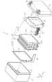
- FIG. 2 is an exploded perspective view showing each component when the power storage device according to the embodiment is disassembled.
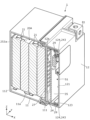
- FIG. 3 is a cross-sectional perspective view showing a joint structure between the exterior body and the power storage unit according to the embodiment.
- FIG. 4 is a cross-sectional perspective view showing a joint structure between an exterior body and a power storage unit according to Modification Example 1.
- a power storage device includes a power storage unit and an exterior body that houses the power storage unit, and the power storage unit includes a plurality of power storage elements arranged in a predetermined direction, It has a first holding member that is adjacent to the plurality of power storage elements in the predetermined direction and holds the plurality of power storage elements, and the first holding member is joined to the exterior body.
- the first holding member provided at the end of the power storage unit is joined to the exterior body, so the power storage unit is fixed at least on one side within the exterior body. It turns out. Thereby, the power storage unit becomes stable within the exterior body. Therefore, it is possible to improve the vibration resistance or impact resistance of the power storage device.
- the exterior body includes an exterior body having an opening at one end in the predetermined direction, and an exterior body that is attached to the one end of the exterior body and opens the opening. It may also have a closing exterior body lid.
- the power storage unit is housed in the exterior main body with one end opened in the predetermined direction, so the first holding member is attached to the other end of the power storage unit in the predetermined direction.
- the first holding member can be joined to the bottom of the exterior body main body. That is, when the power storage unit is housed in the exterior body main body, the first holding member provided at the other end of the power storage unit can be joined to the exterior body main body.
- the first holding member when the first holding member is disposed at one end of the power storage unit in a predetermined direction, the first holding member can be joined to the exterior body lid.
- the first holding member provided at one end of the power storage unit can be joined to the exterior body lid. In this way, it is possible to smoothly join the first holding member provided at the end of the power storage unit to the exterior body.
- the power storage unit further includes a second holding member that holds the plurality of power storage elements, and the second holding member is configured to hold the plurality of power storage elements.
- the power storage element may be disposed at a position sandwiching the plurality of power storage elements together with the first holding member in the direction of , and may be joined to the exterior body.
- the power storage device described in (3) above since the plurality of power storage elements are sandwiched and held by the first holding member and the second holding member, the first holding member and the second holding member The plurality of power storage elements become more stable within the exterior body. Furthermore, since the first holding member is joined to the exterior body and the second holding member is joined to the exterior body, the power storage unit is fixed on both sides within the exterior body. Thereby, it is possible to further improve the vibration resistance or impact resistance of the power storage device.
- a gap is formed between at least one of the first holding member and the second holding member and the exterior body at a position corresponding to the plurality of power storage elements.
- This gap can absorb the expansion of the plurality of power storage elements. Therefore, deformation of the exterior body due to expansion of the plurality of power storage elements can be suppressed.
- a circuit board may be disposed in the gap.
- the circuit board is disposed in the gap between at least one of the first holding member and the second holding member and the exterior body, a dedicated It is possible to accommodate a circuit board without providing any members. If a dedicated member is not required, the weight can be reduced, and the vibration resistance or impact resistance can thereby be further improved. Furthermore, if a dedicated member is not required, it is possible to save space within the exterior body, and the power storage device can be downsized.
- the direction in which the exterior body and the exterior cover of the exterior body of the power storage device are lined up, or the direction in which a plurality of power storage elements included in the power storage device are lined up is defined as the X-axis direction.
- the protruding direction of each lead terminal of the power storage element is defined as the Y-axis direction.
- the direction in which a pair of lead terminals provided on a power storage element are lined up or the vertical direction is defined as the Z-axis direction.
- the X-axis direction is an example of a predetermined direction.
- the Z-axis direction may not be the vertical direction, but for convenience of explanation, the Z-axis direction will be described as the vertical direction below.
- the X-axis plus direction refers to the arrow direction side of the X-axis
- the X-axis minus direction refers to the side opposite to the X-axis plus direction.
- Expressions indicating relative directions or orientations, such as parallel and orthogonal include cases where the directions or orientations are not strictly speaking. Two directions being orthogonal does not only mean that the two directions are completely orthogonal, but also that they are substantially orthogonal, that is, including a difference of a few percent. also means In the following description, when the expression "insulation" is used, it means “electrical insulation”.
- FIG. 1 is a perspective view showing the appearance of a power storage device 1 according to an embodiment.
- FIG. 2 is an exploded perspective view showing each component when power storage device 1 according to the embodiment is disassembled.
- the power storage device 1 is a device that can charge electricity from the outside and discharge electricity to the outside, and has a substantially rectangular parallelepiped shape in this embodiment.
- the power storage device 1 is a battery module (battery assembly) used for power storage, power supply, or the like.
- the power storage device 1 is a battery for driving or starting an engine of a moving object such as an automobile, a motorcycle, a watercraft, a ship, a snowmobile, an agricultural machine, a construction machine, or a railway vehicle for an electric railway. used as.
- Examples of the above-mentioned vehicles include electric vehicles (EVs), hybrid electric vehicles (HEVs), plug-in hybrid electric vehicles (PHEVs), and fossil fuel (gasoline, diesel oil, liquefied natural gas, etc.) vehicles.
- Examples of the above-mentioned railway vehicles for electric railways include electric trains, monorails, linear motor cars, and hybrid electric trains equipped with both a diesel engine and an electric motor.
- the power storage device 1 can also be used as a stationary battery or the like used for home or business purposes.
- the power storage device 1 includes a power storage unit 20 and an exterior body 10 that houses the power storage unit 20.
- the exterior body 10 includes an exterior body body 11 that accommodates the power storage unit 20, and an exterior body lid body 12 that closes the exterior body body 11.
- the exterior body 10 is a rectangular (box-shaped) container (module case) that constitutes the exterior body of the power storage device 1.
- the exterior body 10 is a member that fixes the power storage unit 20 and the like in a predetermined position and protects these elements from impact and the like.
- the exterior body 11 is a rectangular cylindrical member with a bottom that is open in the positive direction of the X-axis, and the open portion is the opening 111.
- the opening 111 has a substantially rectangular shape in plan view (as viewed in the X-axis direction).
- a plurality of bus bars (not shown) and fuses (not shown) held by the power storage unit 20 are accommodated in the opening 111 of the exterior body 11.
- the exterior lid 12 is a member that closes the opening 111 of the exterior body 11, and is joined to the exterior body 11 in a state where the opening 111 of the exterior body 11 is closed from the X-axis positive direction.
- a circuit board 35 is arranged at a position outside the opening 111 that corresponds to the exterior body lid 12 . That is, the circuit board 35 is accommodated between the exterior body 11 and the exterior body lid 12.
- the exterior lid 12 has a pair of external terminals 81 (a positive electrode and a negative electrode). External terminal 81 is electrically connected to a plurality of power storage elements 21 included in power storage unit 20 via each bus bar, fuse, and circuit board 35 . Power storage device 1 charges electricity from the outside via this external terminal 81 and discharges electricity to the outside.
- the external terminal 81 is made of a conductive member made of metal such as a copper alloy such as brass, copper, aluminum, or an aluminum alloy.
- Each bus bar is a plate-like member that electrically connects the external terminal 81 and the power storage element 21.
- Each bus bar is formed of a conductive member made of metal such as copper, copper alloy, aluminum, or aluminum alloy.
- the fuse is a member that protects the circuit board 35, the plurality of power storage elements 21, etc. from a large current exceeding the rated value. A fuse cuts off the flow of current by blowing when a current exceeding its rating flows.
- the circuit board 35 has a plurality of electrical components (not shown), and these electrical components form a detection circuit that detects the state (temperature, voltage, current, etc.) of each power storage element 21, and a detection circuit that controls charging and discharging. A control circuit and the like for control are formed.
- the circuit board 35 only needs to have at least one of a detection circuit and a control circuit.
- the exterior body 11 and exterior body lid 12 of the exterior body 10 are made of polycarbonate (PC), polypropylene (PP), polyethylene (PE), polystyrene (PS), polyphenylene sulfide resin (PPS), polyphenylene ether (PPE (modified PPE) )), polyethylene terephthalate (PET), polybutylene terephthalate (PBT), polyetheretherketone (PEEK), tetrafluoroethylene perfluoroalkyl vinyl ether (PFA), polytetrafluoroethylene (PTFE), polyethersal It is made of an insulating material such as PES (PES), polyamide (PA), ABS resin, or a composite material thereof, or metal coated with an insulating coating.
- PC polycarbonate
- PP polypropylene
- PE polyethylene
- PS polystyrene
- PPS polyphenylene sulfide resin
- PPE polyphenylene ether
- PET polyethylene terephthalate
- the exterior body 10 thereby prevents the power storage element 21 and the like from coming into contact with external metal members and the like.
- the exterior body 10 may be formed of a conductive member such as metal, as long as the electrical insulation of the power storage element 21 and the like is maintained.
- the exterior body 11 and the exterior body lid 12 may be formed of the same material or may be formed of different materials.
- the power storage unit 20 includes a plurality of power storage elements 21 and a holding section 22 that holds the plurality of power storage elements 21.
- the power storage element 21 is a secondary battery (single battery) that can charge and discharge electricity, and more specifically, it is a non-aqueous electrolyte secondary battery such as a lithium ion secondary battery.
- the power storage element 21 is a pouch-type power storage element having a flat shape, and a plurality of (four in this embodiment) pouch-type power storage elements 21 are arranged side by side in the X-axis direction. has been done.
- the power storage element 21 is not a pouch-type power storage element, but may be a flat rectangular parallelepiped (prismatic), cylindrical, long cylinder, or elliptical cylinder, and its size and shape are not limited.
- the number of power storage elements 21 arranged is also not particularly limited.
- the power storage element 21 is not limited to a non-aqueous electrolyte secondary battery, and may be a secondary battery other than a non-aqueous electrolyte secondary battery, or a capacitor.
- the power storage element 21 may be not a secondary battery but a primary battery that allows the user to use the stored electricity without charging it.
- the plurality of power storage elements 21 are arranged in the X-axis direction, and adjacent power storage elements 21 may or may not be joined with adhesive or double-sided tape. Details of the power storage element 21 will be described later.
- the holding part 22 is a part that holds a plurality of power storage elements 21.
- the holding portion 22 includes a holding member 23 and a holding member 24 that holds the plurality of power storage elements 21 together with the holding member 23.
- the holding member 23 is an example of a second holding member, and the holding member 24 is an example of a first holding member.
- the holding member 23 is arranged in the negative X-axis direction of the plurality of power storage elements 21, and is bonded to the power storage element 21 arranged at the end in the negative X-axis direction among the plurality of power storage elements 21. They are joined with adhesive or double-sided tape.
- the holding member 24 is arranged in the X-axis positive direction of the plurality of power storage elements 21, and is attached to the power storage element 21 arranged at the end in the X-axis positive direction among the plurality of power storage elements 21 with adhesive or double-sided tape. It is joined. Thereby, the holding member 23 and the holding member 24 hold the plurality of power storage elements 21 on both sides of the power storage elements 21 in the X-axis direction.
- the holding member 23 can hold the plurality of power storage elements 21 more stably by being arranged to face the center of the power storage elements 21 arranged at the ends in the negative X-axis direction. The same applies to the holding member 24.
- the central part of the power storage element 21 in the Z-axis direction is, for example, the middle three regions when the power storage element 21 is divided into five equal parts in the Z-axis direction, or the middle two regions when the power storage element 21 is divided into four equal parts. This is the area for one area in the middle when divided into three equal parts. The same applies to the Y-axis direction.
- At least one of the holding member 23 and the holding member 24 does not need to be joined to the power storage element 21. Even in this case, the holding members 23 and 24 can hold the plurality of power storage elements 21 by the clamping force received from the exterior body 11 and the exterior body lid 12. In addition to this, a plurality of power storage elements 21 may be held by extending a screw between the holding member 23 and the holding member 24 and tightening the screw.
- the holding member 23 and the holding member 24 are made of polycarbonate (PC), polypropylene (PP), polyethylene (PE), polyphenylene sulfide resin (PPS), polyphenylene ether (PPE (including modified PPE)), polyethylene terephthalate (PET), Polybutylene terephthalate (PBT), polyether ether ketone (PEEK), tetrafluoroethylene perfluoroalkyl vinyl ether (PFA), polytetrafluoroethylene (PTFE), polyether sulfone (PES), polyamide (PA), ABS resin , and an insulating member such as a composite material thereof.
- PC polycarbonate
- PP polypropylene
- PE polyethylene
- PPS polyphenylene sulfide resin
- PPE polyphenylene ether
- PET polyethylene terephthalate
- PBT Polybutylene terephthalate
- PEEK polyether ether ketone
- PTFE polytetrafluoro
- the holding member 23 has a flat plate portion 25 that overlaps the power storage element 21 at the end in the negative direction of the X-axis, and a bus bar support portion 26 that extends from the flat plate portion 25 in the positive direction of the X-axis.
- the bus bar support section 26 extends from the corner of the flat plate section 25 in the Y-axis minus direction and the Z-axis minus direction in the X-axis plus direction, and supports a bus bar (not shown).
- the holding member 24 has a substrate support portion 27 that overlaps the power storage element 21 at the end in the X-axis positive direction, and a detection line support portion 28 that extends from the substrate support portion 27 in the X-axis negative direction.
- the board support part 27 supports a circuit board 35 and has a surrounding wall 29 surrounding the circuit board 35. Further, the substrate support section 27 supports a bus bar and a fuse (not shown).
- the detection line support part 28 is a part that supports a plurality of detection lines 36 connected to the circuit board 35 in order to detect the state (temperature, voltage, current, etc.) of each power storage element 21.
- the detection line support section 28 extends from the end of the substrate support section 27 in the Y-axis minus direction in the X-axis minus direction.
- the plurality of power storage elements 21 have the same basic structure, but have partially different external shapes. Specifically, the outer shapes of the odd-numbered power storage elements 21 in order from the X-axis negative direction and the even-numbered power storage elements 21 in order from the X-axis negative direction are partially different. In other words, the odd-numbered power storage elements 21 have the same outer shape, and the even-numbered power storage elements 21 have the same outer shape.
- the power storage element 21 has an exterior film 210 and a pair of lead terminals 220 (positive electrode and negative electrode), and inside the exterior film 210, an electrode body (not shown) and an electrolyte (non-aqueous electrolyte: not shown) are provided. ) etc. are accommodated.
- an electrode body not shown
- an electrolyte non-aqueous electrolyte: not shown
- the exterior film 210 is a sheet-like exterior body formed of a laminate film, and contains an electrode body, an electrolytic solution, etc. therein in a sealed state under reduced pressure.
- the exterior film 210 is constructed by stacking two rectangular laminate films in the X-axis direction. The two laminate films are joined (sealed) by thermal welding or the like with a pair of lead terminals 220 in between. In the two laminate films, at locations that do not correspond to the pair of lead terminals 220, the two laminate films are joined (sealed) to each other by thermal welding or the like.
- Laminate film is a flexible film consisting of multiple layers including a metal layer such as aluminum and a resin layer such as polypropylene (PP) or polyethylene (PE). has been done.
- the exterior film 210 may be constructed by forming a single laminate film into a bag shape and joining the ends of the laminate film together by thermal welding.
- the lead terminal 220 is a conductive plate-like member (lead plate) that is electrically connected to the electrode body, and is disposed so as to penetrate through the exterior film 210 and be exposed from the exterior film 210.
- a pair of lead terminals 220 aligned in the Z-axis direction are arranged to protrude in the Y-axis minus direction from the end of the exterior film 210 in the Y-axis minus direction.
- the positive electrode lead terminal 220 is a lead terminal electrically connected to the positive electrode plate of the electrode body
- the negative electrode lead terminal 220 is a lead terminal electrically connected to the negative electrode plate of the electrode body. It is.
- the lead terminal 220 is a metal terminal for leading the electricity stored in the electrode body to the external space of the electricity storage element 21 and for introducing electricity into the internal space of the electricity storage element 21 to store electricity in the electrode body. It is an electrode terminal.
- the lead terminal 220 is made of aluminum, aluminum alloy, copper, copper alloy, or the like.
- the electrode body is a power storage element (power generation element) formed by laminating a positive electrode plate, a negative electrode plate, and a separator.
- the positive electrode plate has a positive electrode active material layer formed on a current collector foil made of metal such as aluminum or aluminum alloy.
- the negative electrode plate has a negative electrode active material layer formed on a current collector foil made of metal such as copper or copper alloy.
- the active material used for the positive electrode active material layer and the negative electrode active material layer any known material can be used as appropriate as long as it is capable of intercalating and deintercalating lithium ions.
- As the separator a microporous sheet made of resin, a nonwoven fabric, or the like can be used.
- the electrode body is formed by stacking electrode plates (a positive electrode plate and a negative electrode plate) in the X-axis direction.
- the electrode body is a wound type electrode body formed by winding electrode plates (positive electrode plate and negative electrode plate), and a laminated type (stack type) formed by laminating a plurality of flat electrode plates.
- Any form of electrode body may be used, such as a bellows-shaped electrode body in which an electrode plate is folded into a bellows shape.
- FIG. 3 is a cross-sectional perspective view showing a joint structure between the exterior body and the power storage unit according to the embodiment. Specifically, FIG. 3 is a cross-sectional perspective view taken along the line III--III in FIG. 1.
- a holding member 23 of the power storage unit 20 is joined to the exterior body 11 of the exterior body 10.
- a bottom frame 113 protruding in the positive direction of the X-axis is formed on an inner bottom surface 112 that faces the opening 111 in the X-axis direction.
- the bottom frame 113 is provided continuously or intermittently along the entire periphery of the inner bottom surface 112.
- the bottom frame 113 is arranged at a predetermined distance from the inner surface 11a of the exterior body main body 11.
- the flat plate portion 25 of the holding member 23 is provided with an edge portion 251 that extends continuously or intermittently along the entire circumference.
- the edge portion 251 protrudes from the flat plate portion 25 on both sides in the X-axis direction.
- a first groove 252 that extends continuously or intermittently over the entire circumference is formed on the end surface of the edge 251 in the negative X-axis direction.
- the bottom frame 113 is inserted into the first groove 252 with an adhesive 253 interposed therebetween.
- the first groove 252 and the bottom frame 113 are entirely or partially bonded together with an adhesive 253.
- a holding member 24 of the power storage unit 20 is joined to the exterior body lid 12 of the exterior body 10.
- a lid frame 123 protruding in the X-axis negative direction is formed on an inner top surface 121 that faces the opening 111 in the X-axis positive direction.
- the lid frame 123 is continuous in an annular shape within the inner top surface 121.
- the lid frame 123 is arranged at a predetermined distance from the inner surface 12a of the exterior lid 12.
- a second groove 124 is formed by the lid frame 123 and the inner surface 12a of the exterior lid 12.
- the tip portion (the end portion in the positive X-axis direction) of the surrounding wall 29 of the holding member 24 is inserted into the second groove 124 via the adhesive 243 .
- the surrounding wall 29 of the holding member 24 is bonded to the second groove 124 of the exterior body lid 12 over the entire circumference by being bonded with an adhesive 243.
- the power storage unit 20 is fixed on both sides within the exterior body 10 because the holding member 23 is joined to the exterior body 11 and the retaining member 24 is joined to the exterior body lid 12. Become. In this state, a gap S1 is formed between the substrate support portion 27 and the exterior body lid 12. The gap S1 is arranged at a position corresponding to the plurality of power storage elements 21 when viewed in the X-axis direction. That is, a gap S ⁇ b>1 is formed between the portion of the substrate support portion 27 facing the power storage element 21 and the exterior body lid 12 . Even if the plurality of power storage elements 21 expand, the expansion is absorbed by the gap S1, so that the expansion is difficult to be transmitted to the exterior body lid 12.
- a circuit board 35 is arranged inside the surrounding wall 29 within the gap S1. As described above, the tip of the surrounding wall 29 is adhered to the second groove 124 of the exterior body lid 12 over the entire circumference using the adhesive 243, so that the internal space of the surrounding wall 29 is sealed.
- the operator first applies adhesive 253 to the bottom frame 113 of the exterior body body 11 or the first groove 252 of the holding member 23. Thereafter, the operator arranges the power storage unit 20 in the positive direction of the X-axis of the exterior body 11 and moves the power storage unit 20 in the negative direction of the X-axis to house it in the exterior body 11 through the opening 111. .
- the bottom frame 113 is inserted into the first groove 252. As a result, the first groove 252 and the bottom frame 113 are bonded together with the adhesive 253.
- the operator applies adhesive 243 to the second groove 124 of the exterior lid 12 or the surrounding wall 29 of the holding member 24.
- the operator places the exterior body lid 12 in the X-axis positive direction of the exterior body body 11 and moves the exterior body lid 12 in the X-axis negative direction, thereby attaching the exterior body to the exterior body 11.
- the lid body 12 is assembled and glued.
- the surrounding wall 29 of the holding member 24 is inserted into the second groove 124.
- the second groove 124 and the surrounding wall 29 are bonded together with the adhesive 243. That is, the bonding between the exterior body 11 and the exterior body lid 12 and the bonding between the second groove 124 and the surrounding wall 29 are performed in the same process.
- the exterior film 210 of the power storage element 21 is formed of a flexible laminate film
- the power storage element 21 and the holding members 23 and 24 can be brought into closer contact with each other.
- the holding members 23 and 24 can firmly hold the power storage element 21.
- adjacent power storage elements 21 can be brought into closer contact with each other.
- the holding members 23 and 24 can firmly hold the plurality of power storage elements 21.
- the power storage unit 20 may be assembled to the exterior body 10 in a process opposite to the process described above. That is, after bonding the surrounding wall 29 of the holding member 24 to the second groove portion 124 of the outer case lid 12, the power storage unit 20 is inserted into the outer case main body 11, and the bottom frame 113 of the outer case main body 11 and the holding member 23 may be bonded to the first groove 232.
- the other end of the power storage unit 20 can be opened simply by housing the power storage unit 20 in the exterior body main body 11.
- the holding member 23 provided in the housing can be joined to the exterior body main body 11.
- the holding member 24 provided at one end of the power storage unit 20 can be joined to the exterior lid 12. In this way, the holding members 23 and 24 provided at the ends of the power storage unit 20 can be smoothly joined to the exterior body 10.
- the plurality of power storage elements 21 are held between the holding members 23 and 24, the plurality of power storage elements 21 are made more stable within the exterior body 10 by the holding members 23 and 24. Become. Furthermore, since the holding member 24 is joined to the exterior lid 12 and the holding member 23 is joined to the exterior body 11, the power storage unit 20 is fixed on both sides inside the exterior body 10. . Thereby, it is possible to further improve the vibration resistance or impact resistance of power storage device 1.
- a gap S1 is formed between the holding member 24 and the exterior lid 12 at a position corresponding to the plurality of power storage elements 21, so that the expansion of the plurality of power storage elements 21 can be absorbed by this gap S1. can. Therefore, deformation of the exterior body 10 due to expansion of the plurality of power storage elements 21 can be suppressed.
- the circuit board 35 is arranged in the gap S1, it is possible to accommodate the circuit board 35 without providing a dedicated member to cover the circuit board 35. If a dedicated member is not required, the weight can be reduced, and the vibration resistance or impact resistance can thereby be further improved. Furthermore, if a dedicated member is not required, it is possible to save space within the exterior body 10, and the power storage device 1 can be downsized.
- FIG. 4 is a cross-sectional perspective view showing a joint structure between an exterior body and a power storage unit according to Modification Example 1. Specifically, FIG. 4 is a diagram corresponding to FIG. 3.
- the power storage unit 20A has a holding member 24 that is a first holding member, but does not have a holding member 23 that is a second holding member. Therefore, the end of the power storage unit 20A in the negative X-axis direction is the first power storage element 21 in the negative direction of the X-axis.
- An adhesive 253a is interposed between this first power storage element 21 and the inner bottom surface 112 of the exterior body main body 11, and the power storage element 21 and the inner bottom surface 112 are bonded and joined. That is, also in this case, power storage unit 20A is fixed on both sides within exterior body 10.
- the holding member 24 is an example of the first holding member, and the holding member 23 is an example of the second holding member.
- the holding member 23 may be an example of a first holding member
- the holding member 24 may be an example of a second holding member.
- the holding member 24 can be removed as in Modification 1, and the fourth electricity storage element 21 can be joined (adhered) to the exterior body lid 12.
- the second holding member does not need to be joined to the exterior body. Also in this case, since the power storage unit is fixed on one side within the exterior body, the power storage unit is stabilized within the exterior body. Therefore, it is possible to improve the vibration resistance or impact resistance of the power storage device.
- adhesion is exemplified as a method for joining objects to be joined.
- the objects to be joined may be joined by a method other than adhesion.
- Other methods include welding, fixing with bolts and nuts, and the like.
- the gap S1 is formed between the substrate support part 27 of the holding member 24 and the exterior body lid 12 is illustrated.
- a gap may be provided between the holding member 23 and the inner bottom surface 112 of the exterior body main body 11. Even with this gap, expansion of the power storage element 21 can be absorbed, and deformation of the exterior body due to the expansion can be suppressed.
- the gap may be provided in at least one of the holding member 24 and the outer case lid 12 and between the holding member 23 and the outer case main body 11. Note that the gap may not be provided.
- the circuit board 35 is arranged in the gap S1 between the board support part 27 of the holding member 24 and the exterior body lid 12 is illustrated.
- the circuit board 35 may be placed in the gap. Note that the circuit board does not need to be placed within the gap.
- the exterior body main body 11 has an opening 111 at the end in the X-axis direction (predetermined direction), but the opening may be located in any position.
- the exterior body may have an opening at the end in the direction intersecting the X-axis direction.
- Embodiments constructed by arbitrarily combining components included in the embodiments and their modifications are also included within the scope of the present invention.
- the present invention can be applied to power storage devices and the like that include power storage elements such as lithium ion secondary batteries.
- Power storage device 10 Exterior body 11 Exterior body main bodies 11a, 12a Inner surface 12 Exterior body cover bodies 20, 20A Power storage unit 21 Power storage element 22 Holding part 23 Holding member (second holding member) 24 Holding member (first holding member) 25 Flat plate part 26 Bus bar support part 27 Board support part 28 Detection line support part 29 Surrounding wall 35 Circuit board 36 Detection line 81 External terminal 111 Opening 112 Inner bottom surface 113 Bottom frame 121 Inner top surface 123 Lid frame 124 Second groove 210 Exterior film 220 Lead terminals 243, 253, 253a Adhesive 251 Edge 252 First groove S1 Gap
Landscapes
- Chemical & Material Sciences (AREA)
- Chemical Kinetics & Catalysis (AREA)
- Electrochemistry (AREA)
- General Chemical & Material Sciences (AREA)
- Battery Mounting, Suspending (AREA)
Priority Applications (3)
| Application Number | Priority Date | Filing Date | Title |
|---|---|---|---|
| US18/992,186 US20260005354A1 (en) | 2022-07-08 | 2023-07-03 | Energy storage apparatus |
| CN202380049550.XA CN119404359A (zh) | 2022-07-08 | 2023-07-03 | 蓄电装置 |
| JP2024532111A JPWO2024009930A1 (https=) | 2022-07-08 | 2023-07-03 |
Applications Claiming Priority (2)
| Application Number | Priority Date | Filing Date | Title |
|---|---|---|---|
| JP2022110752 | 2022-07-08 | ||
| JP2022-110752 | 2022-07-08 |
Publications (1)
| Publication Number | Publication Date |
|---|---|
| WO2024009930A1 true WO2024009930A1 (ja) | 2024-01-11 |
Family
ID=89453327
Family Applications (1)
| Application Number | Title | Priority Date | Filing Date |
|---|---|---|---|
| PCT/JP2023/024557 Ceased WO2024009930A1 (ja) | 2022-07-08 | 2023-07-03 | 蓄電装置 |
Country Status (4)
| Country | Link |
|---|---|
| US (1) | US20260005354A1 (https=) |
| JP (1) | JPWO2024009930A1 (https=) |
| CN (1) | CN119404359A (https=) |
| WO (1) | WO2024009930A1 (https=) |
Citations (5)
| Publication number | Priority date | Publication date | Assignee | Title |
|---|---|---|---|---|
| WO2017047683A1 (ja) * | 2015-09-18 | 2017-03-23 | 株式会社Gsユアサ | 蓄電装置 |
| JP2017069004A (ja) * | 2015-09-29 | 2017-04-06 | 株式会社Gsユアサ | 蓄電装置及び蓄電装置の製造方法 |
| WO2021149300A1 (ja) * | 2020-01-23 | 2021-07-29 | 三洋電機株式会社 | 電池モジュール、電池モジュールを備える電源装置、電源装置を備える電動車両及び蓄電装置 |
| WO2022045591A1 (ko) * | 2020-08-26 | 2022-03-03 | 주식회사 엘지에너지솔루션 | 대형 배터리 모듈 및 이를 포함하는 배터리 팩 |
| JP2023046013A (ja) * | 2021-09-22 | 2023-04-03 | トヨタ自動車株式会社 | 電池パック |
-
2023
- 2023-07-03 JP JP2024532111A patent/JPWO2024009930A1/ja active Pending
- 2023-07-03 WO PCT/JP2023/024557 patent/WO2024009930A1/ja not_active Ceased
- 2023-07-03 US US18/992,186 patent/US20260005354A1/en active Pending
- 2023-07-03 CN CN202380049550.XA patent/CN119404359A/zh active Pending
Patent Citations (5)
| Publication number | Priority date | Publication date | Assignee | Title |
|---|---|---|---|---|
| WO2017047683A1 (ja) * | 2015-09-18 | 2017-03-23 | 株式会社Gsユアサ | 蓄電装置 |
| JP2017069004A (ja) * | 2015-09-29 | 2017-04-06 | 株式会社Gsユアサ | 蓄電装置及び蓄電装置の製造方法 |
| WO2021149300A1 (ja) * | 2020-01-23 | 2021-07-29 | 三洋電機株式会社 | 電池モジュール、電池モジュールを備える電源装置、電源装置を備える電動車両及び蓄電装置 |
| WO2022045591A1 (ko) * | 2020-08-26 | 2022-03-03 | 주식회사 엘지에너지솔루션 | 대형 배터리 모듈 및 이를 포함하는 배터리 팩 |
| JP2023046013A (ja) * | 2021-09-22 | 2023-04-03 | トヨタ自動車株式会社 | 電池パック |
Also Published As
| Publication number | Publication date |
|---|---|
| JPWO2024009930A1 (https=) | 2024-01-11 |
| US20260005354A1 (en) | 2026-01-01 |
| CN119404359A (zh) | 2025-02-07 |
Similar Documents
| Publication | Publication Date | Title |
|---|---|---|
| WO2022130999A1 (ja) | 蓄電装置 | |
| WO2023223961A1 (ja) | 蓄電装置 | |
| JP2021132016A (ja) | 蓄電装置 | |
| JP2021111562A (ja) | 蓄電装置 | |
| WO2023013466A1 (ja) | 蓄電装置 | |
| US20250192334A1 (en) | Energy storage apparatus | |
| CN113261149A (zh) | 蓄电装置 | |
| JP7451915B2 (ja) | 蓄電素子 | |
| JP7427903B2 (ja) | 蓄電装置 | |
| WO2022255162A1 (ja) | 蓄電装置 | |
| JP7658065B2 (ja) | 蓄電装置 | |
| JP2023100001A (ja) | 蓄電装置 | |
| WO2024009930A1 (ja) | 蓄電装置 | |
| JP7524551B2 (ja) | 蓄電装置 | |
| WO2022163668A1 (ja) | 蓄電装置 | |
| JP2023090507A (ja) | 蓄電装置 | |
| US20260024862A1 (en) | Energy storage apparatus | |
| US20260081309A1 (en) | Energy storage apparatus and method for manufacturing the same | |
| WO2024038730A1 (ja) | 蓄電装置 | |
| WO2024038729A1 (ja) | 蓄電装置 | |
| US20240372197A1 (en) | Energy storage apparatus | |
| WO2023171117A1 (ja) | 蓄電装置 | |
| JP7552032B2 (ja) | 蓄電装置 | |
| WO2024009928A1 (ja) | 蓄電素子及び蓄電装置 | |
| WO2025220638A1 (ja) | 蓄電装置 |
Legal Events
| Date | Code | Title | Description |
|---|---|---|---|
| 121 | Ep: the epo has been informed by wipo that ep was designated in this application |
Ref document number: 23835462 Country of ref document: EP Kind code of ref document: A1 |
|
| WWE | Wipo information: entry into national phase |
Ref document number: 2024532111 Country of ref document: JP |
|
| WWE | Wipo information: entry into national phase |
Ref document number: 202380049550.X Country of ref document: CN |
|
| WWE | Wipo information: entry into national phase |
Ref document number: 18992186 Country of ref document: US |
|
| WWP | Wipo information: published in national office |
Ref document number: 202380049550.X Country of ref document: CN |
|
| NENP | Non-entry into the national phase |
Ref country code: DE |
|
| 122 | Ep: pct application non-entry in european phase |
Ref document number: 23835462 Country of ref document: EP Kind code of ref document: A1 |
|
| WWP | Wipo information: published in national office |
Ref document number: 18992186 Country of ref document: US |