WO2024009646A1 - バンパキャップおよび緩衝器 - Google Patents
バンパキャップおよび緩衝器 Download PDFInfo
- Publication number
- WO2024009646A1 WO2024009646A1 PCT/JP2023/019754 JP2023019754W WO2024009646A1 WO 2024009646 A1 WO2024009646 A1 WO 2024009646A1 JP 2023019754 W JP2023019754 W JP 2023019754W WO 2024009646 A1 WO2024009646 A1 WO 2024009646A1
- Authority
- WO
- WIPO (PCT)
- Prior art keywords
- cylindrical portion
- edge
- axial direction
- axial
- bumper cap
- Prior art date
- Legal status (The legal status is an assumption and is not a legal conclusion. Google has not performed a legal analysis and makes no representation as to the accuracy of the status listed.)
- Ceased
Links
Images


Classifications
-
- F—MECHANICAL ENGINEERING; LIGHTING; HEATING; WEAPONS; BLASTING
- F16—ENGINEERING ELEMENTS AND UNITS; GENERAL MEASURES FOR PRODUCING AND MAINTAINING EFFECTIVE FUNCTIONING OF MACHINES OR INSTALLATIONS; THERMAL INSULATION IN GENERAL
- F16F—SPRINGS; SHOCK-ABSORBERS; MEANS FOR DAMPING VIBRATION
- F16F9/00—Springs, vibration-dampers, shock-absorbers, or similarly-constructed movement-dampers using a fluid or the equivalent as damping medium
- F16F9/32—Details
- F16F9/38—Covers for protection or appearance
-
- B—PERFORMING OPERATIONS; TRANSPORTING
- B22—CASTING; POWDER METALLURGY
- B22D—CASTING OF METALS; CASTING OF OTHER SUBSTANCES BY THE SAME PROCESSES OR DEVICES
- B22D25/00—Special casting characterised by the nature of the product
-
- B—PERFORMING OPERATIONS; TRANSPORTING
- B29—WORKING OF PLASTICS; WORKING OF SUBSTANCES IN A PLASTIC STATE IN GENERAL
- B29C—SHAPING OR JOINING OF PLASTICS; SHAPING OF MATERIAL IN A PLASTIC STATE, NOT OTHERWISE PROVIDED FOR; AFTER-TREATMENT OF THE SHAPED PRODUCTS, e.g. REPAIRING
- B29C45/00—Injection moulding, i.e. forcing the required volume of moulding material through a nozzle into a closed mould; Apparatus therefor
- B29C45/0001—Injection moulding, i.e. forcing the required volume of moulding material through a nozzle into a closed mould; Apparatus therefor characterised by the choice of material
-
- F—MECHANICAL ENGINEERING; LIGHTING; HEATING; WEAPONS; BLASTING
- F16—ENGINEERING ELEMENTS AND UNITS; GENERAL MEASURES FOR PRODUCING AND MAINTAINING EFFECTIVE FUNCTIONING OF MACHINES OR INSTALLATIONS; THERMAL INSULATION IN GENERAL
- F16F—SPRINGS; SHOCK-ABSORBERS; MEANS FOR DAMPING VIBRATION
- F16F9/00—Springs, vibration-dampers, shock-absorbers, or similarly-constructed movement-dampers using a fluid or the equivalent as damping medium
- F16F9/10—Springs, vibration-dampers, shock-absorbers, or similarly-constructed movement-dampers using a fluid or the equivalent as damping medium using liquid only; using a fluid of which the nature is immaterial
- F16F9/14—Devices with one or more members, e.g. pistons, vanes, moving to and fro in chambers and using throttling effect
- F16F9/16—Devices with one or more members, e.g. pistons, vanes, moving to and fro in chambers and using throttling effect involving only straight-line movement of the effective parts
- F16F9/18—Devices with one or more members, e.g. pistons, vanes, moving to and fro in chambers and using throttling effect involving only straight-line movement of the effective parts with a closed cylinder and a piston separating two or more working spaces therein
- F16F9/185—Bitubular units
-
- F—MECHANICAL ENGINEERING; LIGHTING; HEATING; WEAPONS; BLASTING
- F16—ENGINEERING ELEMENTS AND UNITS; GENERAL MEASURES FOR PRODUCING AND MAINTAINING EFFECTIVE FUNCTIONING OF MACHINES OR INSTALLATIONS; THERMAL INSULATION IN GENERAL
- F16F—SPRINGS; SHOCK-ABSORBERS; MEANS FOR DAMPING VIBRATION
- F16F9/00—Springs, vibration-dampers, shock-absorbers, or similarly-constructed movement-dampers using a fluid or the equivalent as damping medium
- F16F9/32—Details
- F16F9/3207—Constructional features
- F16F9/3235—Constructional features of cylinders
- F16F9/3242—Constructional features of cylinders of cylinder ends, e.g. caps
-
- F—MECHANICAL ENGINEERING; LIGHTING; HEATING; WEAPONS; BLASTING
- F16—ENGINEERING ELEMENTS AND UNITS; GENERAL MEASURES FOR PRODUCING AND MAINTAINING EFFECTIVE FUNCTIONING OF MACHINES OR INSTALLATIONS; THERMAL INSULATION IN GENERAL
- F16F—SPRINGS; SHOCK-ABSORBERS; MEANS FOR DAMPING VIBRATION
- F16F9/00—Springs, vibration-dampers, shock-absorbers, or similarly-constructed movement-dampers using a fluid or the equivalent as damping medium
- F16F9/32—Details
- F16F9/58—Stroke limiting stops, e.g. arranged on the piston rod outside the cylinder
-
- B—PERFORMING OPERATIONS; TRANSPORTING
- B29—WORKING OF PLASTICS; WORKING OF SUBSTANCES IN A PLASTIC STATE IN GENERAL
- B29K—INDEXING SCHEME ASSOCIATED WITH SUBCLASSES B29B, B29C OR B29D, RELATING TO MOULDING MATERIALS OR TO MATERIALS FOR MOULDS, REINFORCEMENTS, FILLERS OR PREFORMED PARTS, e.g. INSERTS
- B29K2995/00—Properties of moulding materials, reinforcements, fillers, preformed parts or moulds
- B29K2995/0037—Other properties
- B29K2995/0091—Damping, energy absorption
-
- B—PERFORMING OPERATIONS; TRANSPORTING
- B29—WORKING OF PLASTICS; WORKING OF SUBSTANCES IN A PLASTIC STATE IN GENERAL
- B29L—INDEXING SCHEME ASSOCIATED WITH SUBCLASS B29C, RELATING TO PARTICULAR ARTICLES
- B29L2031/00—Other particular articles
- B29L2031/721—Vibration dampening equipment, e.g. shock absorbers
-
- B—PERFORMING OPERATIONS; TRANSPORTING
- B60—VEHICLES IN GENERAL
- B60G—VEHICLE SUSPENSION ARRANGEMENTS
- B60G13/00—Resilient suspensions characterised by arrangement, location or type of vibration dampers
- B60G13/02—Resilient suspensions characterised by arrangement, location or type of vibration dampers having dampers dissipating energy, e.g. frictionally
- B60G13/06—Resilient suspensions characterised by arrangement, location or type of vibration dampers having dampers dissipating energy, e.g. frictionally of fluid type
- B60G13/08—Resilient suspensions characterised by arrangement, location or type of vibration dampers having dampers dissipating energy, e.g. frictionally of fluid type hydraulic
-
- B—PERFORMING OPERATIONS; TRANSPORTING
- B60—VEHICLES IN GENERAL
- B60G—VEHICLE SUSPENSION ARRANGEMENTS
- B60G2202/00—Indexing codes relating to the type of spring, damper or actuator
- B60G2202/20—Type of damper
- B60G2202/24—Fluid damper
-
- B—PERFORMING OPERATIONS; TRANSPORTING
- B60—VEHICLES IN GENERAL
- B60G—VEHICLE SUSPENSION ARRANGEMENTS
- B60G2206/00—Indexing codes related to the manufacturing of suspensions: constructional features, the materials used, procedures or tools
- B60G2206/01—Constructional features of suspension elements, e.g. arms, dampers, springs
- B60G2206/40—Constructional features of dampers and/or springs
- B60G2206/41—Dampers
-
- B—PERFORMING OPERATIONS; TRANSPORTING
- B60—VEHICLES IN GENERAL
- B60G—VEHICLE SUSPENSION ARRANGEMENTS
- B60G2206/00—Indexing codes related to the manufacturing of suspensions: constructional features, the materials used, procedures or tools
- B60G2206/01—Constructional features of suspension elements, e.g. arms, dampers, springs
- B60G2206/80—Manufacturing procedures
- B60G2206/81—Shaping
- B60G2206/8101—Shaping by casting
- B60G2206/81012—Shaping by casting by injection moulding
-
- B—PERFORMING OPERATIONS; TRANSPORTING
- B60—VEHICLES IN GENERAL
- B60G—VEHICLE SUSPENSION ARRANGEMENTS
- B60G2800/00—Indexing codes relating to the type of movement or to the condition of the vehicle and to the end result to be achieved by the control action
- B60G2800/16—Running
- B60G2800/162—Reducing road induced vibrations
-
- F—MECHANICAL ENGINEERING; LIGHTING; HEATING; WEAPONS; BLASTING
- F16—ENGINEERING ELEMENTS AND UNITS; GENERAL MEASURES FOR PRODUCING AND MAINTAINING EFFECTIVE FUNCTIONING OF MACHINES OR INSTALLATIONS; THERMAL INSULATION IN GENERAL
- F16F—SPRINGS; SHOCK-ABSORBERS; MEANS FOR DAMPING VIBRATION
- F16F2222/00—Special physical effects, e.g. nature of damping effects
- F16F2222/12—Fluid damping
-
- F—MECHANICAL ENGINEERING; LIGHTING; HEATING; WEAPONS; BLASTING
- F16—ENGINEERING ELEMENTS AND UNITS; GENERAL MEASURES FOR PRODUCING AND MAINTAINING EFFECTIVE FUNCTIONING OF MACHINES OR INSTALLATIONS; THERMAL INSULATION IN GENERAL
- F16F—SPRINGS; SHOCK-ABSORBERS; MEANS FOR DAMPING VIBRATION
- F16F2226/00—Manufacturing; Treatments
- F16F2226/04—Assembly or fixing methods; methods to form or fashion parts
-
- F—MECHANICAL ENGINEERING; LIGHTING; HEATING; WEAPONS; BLASTING
- F16—ENGINEERING ELEMENTS AND UNITS; GENERAL MEASURES FOR PRODUCING AND MAINTAINING EFFECTIVE FUNCTIONING OF MACHINES OR INSTALLATIONS; THERMAL INSULATION IN GENERAL
- F16F—SPRINGS; SHOCK-ABSORBERS; MEANS FOR DAMPING VIBRATION
- F16F2230/00—Purpose; Design features
- F16F2230/0023—Purpose; Design features protective
-
- F—MECHANICAL ENGINEERING; LIGHTING; HEATING; WEAPONS; BLASTING
- F16—ENGINEERING ELEMENTS AND UNITS; GENERAL MEASURES FOR PRODUCING AND MAINTAINING EFFECTIVE FUNCTIONING OF MACHINES OR INSTALLATIONS; THERMAL INSULATION IN GENERAL
- F16F—SPRINGS; SHOCK-ABSORBERS; MEANS FOR DAMPING VIBRATION
- F16F2230/00—Purpose; Design features
- F16F2230/36—Holes, slots or the like
-
- F—MECHANICAL ENGINEERING; LIGHTING; HEATING; WEAPONS; BLASTING
- F16—ENGINEERING ELEMENTS AND UNITS; GENERAL MEASURES FOR PRODUCING AND MAINTAINING EFFECTIVE FUNCTIONING OF MACHINES OR INSTALLATIONS; THERMAL INSULATION IN GENERAL
- F16F—SPRINGS; SHOCK-ABSORBERS; MEANS FOR DAMPING VIBRATION
- F16F2234/00—Shape
- F16F2234/02—Shape cylindrical
Definitions
- the side of the cylinder from which the rod protrudes is covered with a bumper cap (for example, see Patent Document 1).
- shock absorbers it is desired to improve the durability of bumper caps.
- the present invention aims to provide a bumper cap and a shock absorber that can improve durability.
- one aspect of the present invention is a bumper cap used for a shock absorber, wherein the shock absorber includes a cylinder, a piston provided in the cylinder, and a first end portion of which is connected to the piston. a piston rod connected to the cylinder and having a second end extending from the cylinder, the bumper cap being provided at an end of the cylinder on the side from which the piston rod extends, and formed by die casting or injection molding.
- a lid portion that is molded and has a through hole that comes into contact with the axial end surface of the cylinder and through which the piston rod is inserted; It has a cylindrical portion to cover, and a communication hole provided in the tube portion and communicating between the inner circumferential surface and the outer circumferential surface of the tube portion, and the edge of the communication hole is formed so that the material does not leak during molding.
- a configuration is adopted in which the first end located on the downstream side is thinner than the second end located on the upstream side where the fluid flows.
- Another aspect of the present invention includes a cylinder, a piston provided in the cylinder, and a piston rod having one end connected to the piston and the other end extending from the cylinder, the piston rod of the cylinder a bumper cap of the shock absorber, which is provided at an end on the side where the bumper cap extends, and the bumper cap comes into contact with an axial end surface of the cylinder and has a through hole through which the piston rod is inserted; a cylindrical tube section provided radially outward from the through hole and covering at least a portion of the outer circumferential surface of the cylinder; and a cylindrical tube section provided in the tube section between the inner circumferential surface and the outer circumferential surface of the tube section.
- a communication hole that communicates with the cylindrical portion, and an edge of the communication hole has a circumferential edge extending in the circumferential direction of the cylindrical portion and an axial edge extending in the axial direction of the cylindrical portion. and at least a part of the circumferential edge includes an inclined part that is formed to be inclined with respect to the axial direction of the cylindrical part and is an end side of the edge of the communication hole in the axial direction of the cylindrical part.
- Still another aspect of the present invention includes a cylinder, a piston provided in the cylinder, a piston rod having one end connected to the piston and the other end extending from the cylinder, and a bumper cap,
- a bumper cap is provided at a radially outer end of the lid, and includes a lid portion that abuts an axial end surface of the cylinder and has a through hole through which the piston rod is inserted, and a bumper cap that is provided at a radially outer end portion of the lid portion, and includes a bumper cap that contacts an axial end surface of the cylinder and has a through hole through which the piston rod is inserted.
- a shock absorber is employed in which the first end located on the downstream side is thinner than the second end located on the upstream side of the inflow.
- the durability of the bumper cap can be improved.
- FIG. 1 is a partially sectional front view showing a shock absorber including a bumper cap according to a first embodiment of the present invention.
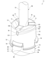
- FIG. 2 is an enlarged perspective view showing main parts of a shock absorber including a bumper cap according to the first embodiment.
- FIG. 3 is a developed view showing a communication hole of a bumper cap of the shock absorber according to the first embodiment.
- FIG. 2 is a developed cross-sectional view showing a mold part forming a communication hole of a mold forming a bumper cap of the shock absorber according to the first embodiment.
- FIG. 7 is a developed view showing a communication hole of a bumper cap of a shock absorber according to a second embodiment of the present invention.
- FIG. 1 is a partially sectional front view showing a shock absorber including a bumper cap according to a first embodiment of the present invention.
- FIG. 2 is an enlarged perspective view showing main parts of a shock absorber including a bumper cap according to the first embodiment.
- FIG. 3 is a developed view
- FIG. 7 is a developed view showing a communication hole of a bumper cap of a shock absorber according to a third embodiment of the present invention.
- FIG. 7 is a developed view showing a communication hole of a bumper cap of a shock absorber according to a fourth embodiment of the present invention.
- FIG. 7 is a developed view showing a communication hole of a bumper cap of a shock absorber according to a fifth embodiment of the present invention.
- FIG. 7 is a developed view showing a communication hole of a bumper cap of a shock absorber according to a sixth embodiment of the present invention.
- FIG. 7 is a developed view showing a communication hole of a bumper cap of a shock absorber according to a seventh embodiment of the present invention.
- FIG. 7 is a developed view showing a communication hole of a bumper cap of a shock absorber according to a ninth embodiment of the present invention.
- FIG. 1 shows a shock absorber according to the first embodiment.
- the shock absorber 11 of the first embodiment is a dual-tube hydraulic shock absorber.
- the shock absorber 11 is used in a strut-type suspension device for a vehicle, specifically, an automobile.
- the shock absorber 11 has a shock absorber main body 12 and a bumper cap 13.
- the shock absorber body 12 includes a cylinder 21, a main bracket 22, a spring seat 23, and a sub-bracket 24.
- the cylinder 21 has an inner cylinder 31 and an outer cylinder 32, both of which are made of metal.
- the inner cylinder 31 has a cylindrical shape.
- the outer cylinder 32 has a cylindrical shape with a bottom.
- the inner cylinder 31 is arranged radially inside the outer cylinder 32.
- a reservoir chamber 33 is formed between the inner cylinder 31 and the outer cylinder 32.
- an inner tube 31 is filled with oil L as a working fluid
- a reservoir chamber 33 is filled with oil L and gas G as working fluid.
- the outer cylinder 32 has a cylindrical body 36 and a bottom 37 that closes one end of the body 36 in the axial direction.
- the outer cylinder 32 has an opening at an end opposite to the bottom 37 in the axial direction of the body 36 .
- the main bracket 22 is made of metal, and is fitted into the body 36 on the bottom 37 side of the axial center of the outer cylinder 32 and fixed by welding.
- the main bracket 22 is connected to the vehicle wheel (not shown) using fasteners (not shown) inserted into a plurality of mounting holes 39 .
- the spring seat 23 is made of metal, and is fitted into the body part 36 on the opposite side of the bottom part 37 from the axial center position of the outer cylinder 32 and fixed by welding.
- the spring seat 23 supports the lower end of a vehicle body support spring (not shown), which is a coil spring that supports the vehicle body (not shown).
- the sub-bracket 24 is made of metal and is fixed to the outer peripheral side of the main bracket 22 by welding.
- the sub-bracket 24 supports harnesses, hoses, etc. that are routed around the shock absorber 11.
- the shock absorber main body 12 has a piston 40 provided within the cylinder 21.
- the piston 40 is slidably fitted into the inner tube 31 of the cylinder 21.
- the piston 40 defines a first chamber 41 and a second chamber 42 within the inner cylinder 31.
- the first chamber 41 is provided on the opposite side of the bottom portion 37 from the piston 40 in the axial direction of the inner cylinder 31 .
- the second chamber 42 is provided closer to the bottom 37 than the piston 40 in the axial direction of the inner cylinder 31 .
- the shock absorber body 12 includes a piston rod 50.
- One end of the piston rod 50 in the axial direction is disposed within the inner tube 31 of the cylinder 21 .
- the first end of the piston rod 50 is connected to the piston 40.
- the piston rod 50 has a second end, which is the other end opposite to the first end, extending from the cylinder 21 to the outside of the cylinder 21 in the axial direction.
- the piston rod 50 has a main shaft portion 51 and a mounting shaft portion 52.
- the main shaft portion 51 and the attachment shaft portion 52 are both rod-shaped.
- the attachment shaft portion 52 has an outer diameter smaller than the outer diameter of the main shaft portion 51.
- the mounting shaft portion 52 is arranged within the inner cylinder 31.
- the piston rod 50 has the piston 40 attached to a mounting shaft portion 52. The piston 40 moves together with the piston rod 50.
- the piston 40 is formed with a passage 54 and a passage 55 that penetrate in the axial direction. Both the passage 54 and the passage 55 allow the first chamber 41 and the second chamber 42 to communicate with each other.
- the shock absorber body 12 includes a disc valve 56 and a disc valve 57.
- the disc valve 56 is provided on the opposite side of the piston 40 from the bottom 37 in the axial direction.
- the disc valve 56 can close the passage 54 by coming into contact with the piston 40.
- the disc valve 57 is provided on the bottom 37 side of the piston 40 in the axial direction.
- the disc valve 57 can close the passage 55 by coming into contact with the piston 40.
- the disc valve 56 and the disc valve 57 are attached together with the piston 40 to the attachment shaft portion 52 of the piston rod 50 with a nut 59.
- the disc valve 56 moves to the contraction side where the piston rod 50 increases the amount of entry into the cylinder 21, and the piston 40 moves in a direction to narrow the second chamber 42, so that the pressure in the second chamber 42 becomes the pressure in the first chamber 41.
- the passage 54 is opened to allow the oil L to flow.
- the disc valve 56 generates a damping force.
- At least one of the piston 40 and the disc valve 56 includes a fixed orifice (not shown) that communicates the first chamber 41 and the second chamber 42 via the passage 54 even when the disc valve 56 has the passage 54 most closed. is provided.
- the piston rod 50 moves to the extension side to increase the amount of protrusion from the cylinder 21, and the piston 40 moves in a direction to narrow the first chamber 41, so that the pressure in the first chamber 41 becomes lower than the pressure in the second chamber 42.
- the passage 55 is opened to allow the oil L to flow.
- the disc valve 57 generates a damping force.
- At least one of the piston 40 and the disc valve 57 has a fixed orifice (not shown) that allows communication between the first chamber 41 and the second chamber 42 via the passage 55 even when the disc valve 57 has the passage 55 most closed. ) is provided.
- the bumper cap 13 is provided at the end of the cylinder 21 on the side from which the piston rod 50 extends, so as to cover this end.
- the shock absorber main body 12 has a sealing member (not shown) that seals a gap between the cylinder 21 and the piston rod 50 at the outer end of the cylinder 21 on the side from which the piston rod 50 projects.
- the bumper cap 13 covers and protects this seal member.
- a bump rubber (not shown) is provided on the piston rod 50 at a portion that projects outward from the seal member in the axial direction.
- This bump rubber is made of a cylindrical elastic material, into which the piston rod 50 is inserted.
- the bumper cap 13 used in the shock absorber 11 has a cylindrical shape with a lid. As shown in FIG. 2, the bumper cap 13 includes a lid portion 70, an axial protrusion 71, a cylindrical portion 72, a flange 73, and a radial protrusion 74.
- the lid portion 70 is in the shape of a perforated disc, and has a through hole 81 that penetrates in the axial direction at the center in the radial direction.
- the through hole 81 is a circular hole.
- the inner peripheral edge portion 82 of the through hole 81 has a circular shape.
- the axial protrusion 71 protrudes from the lid 70 to one side in the axial direction of the lid 70.
- the axial protrusion 71 is partially provided in the circumferential direction of the lid 70 .
- the axial protrusion 71 extends linearly outward from the inner circumferential edge 82 of the lid 70 along the radial direction of the lid 70 .
- the bumper cap 13 is provided with a plurality of axial protrusions 71 having the same shape on the same axial side of the lid 70 at equal intervals in the circumferential direction of the lid 70, specifically, at three locations.
- the cylinder part 72 has a cylindrical shape and extends from the entire circumference of the outer peripheral edge of the lid part 70 to the opposite side from the axial protrusion part 71 in the axial direction of the lid part 70 so as to be coaxial with the lid part 70.
- the cylindrical portion 72 is provided at the radially outer end of the lid portion 70 .
- the cylindrical portion 72 is provided radially outward from the through hole 81 provided in the radial center of the lid portion 70 .
- the cylindrical portion 72 has a concave portion 83 that is recessed in the axial direction from the end surface opposite to the lid portion 70 in the axial direction.
- the concave portion 83 penetrates the cylindrical portion 72 in the radial direction of the cylindrical portion 72 .
- the cylindrical portion 72 is provided with a plurality of concave portions 83, specifically three, having the same shape at predetermined equal intervals in the circumferential direction of the cylindrical portion 72. Each of these concave portions 83 matches the phase of the cylindrical portion 72 in the circumferential direction with one of the axial protrusions 71 .
- the cylindrical portion 72 has an opening 85 on the side opposite to the lid portion 70 in the axial direction.
- the opening 85 includes a plurality of concave portions 83 .
- the bumper cap 13 has an opening 85 at one axial end, and an axial protrusion 71, a lid 70, and a through hole 81 passing through the lid 70 at the other axial end. ing.
- the central axis of the through hole 81, the lid part 70, and the cylindrical part 72, which are arranged coaxially, is the central axis of the bumper cap 13. Therefore, the through hole 81, the lid part 70, the cylinder part 72, and the bumper cap 13 are aligned in the axial direction, aligned in the circumferential direction, and aligned in the radial direction.
- the flange portion 73 protrudes outward in the radial direction of the tube portion 72 from the end edge of the tube portion 72 on the side opposite to the lid portion 70 in the axial direction.
- the flange portion 73 is partially provided in the circumferential direction of the cylindrical portion 72 .
- the flange portion 73 is formed between adjacent concave portions 83 of the end edge portion of the cylinder portion 72 on the opposite side from the lid portion 70 in the axial direction.
- a plurality of flange portions 73 having the same shape are provided at equal intervals in the circumferential direction of the cylindrical portion 72, specifically, at three locations. These collar portions 73 are aligned with the axial direction of the cylindrical portion 72 .
- the radial protruding portion 74 protrudes outward in the radial direction of the cylindrical portion 72 from between the lid portion 70 and the flange portion 73 in the axial direction of the cylindrical portion 72 .
- the radial protrusion 74 is partially provided in the circumferential direction of the cylindrical portion 72 .
- the radial protrusion 74 is provided at the position of the concave portion 83 of the end edge of the cylinder portion 72 on the side opposite to the lid portion 70 in the axial direction.
- a plurality of radial protrusions 74 having the same shape are provided at equal intervals in the circumferential direction of the cylindrical portion 72, specifically, at three locations.
- These radial protrusions 74 are aligned with the axial direction of the cylindrical portion 72 .
- Each of these radial protrusions 74 matches the phase of the lid 70 in the circumferential direction with one of the axial protrusions 71 .
- the radial protrusion 74 is located at a different position from the flange 73 in the circumferential direction of the cylindrical portion 72 .
- the radial protrusions 74 and the flange portions 73 are alternately arranged at equal intervals in the circumferential direction of the cylindrical portion 72.
- a communication hole 91 that penetrates the cylinder part 72 in the radial direction of the cylinder part 72 is formed in the cylinder part 72 at a position between the radial protrusion part 74 and the lid part 70 in the axial direction of the cylinder part 72. .
- the communication hole 91 is provided in the cylindrical portion 72 and communicates between the inner circumferential surface 72a and the outer circumferential surface 72b shown in FIG. 1 of the cylindrical portion 72.
- the communication hole 91 is a horizontal hole that penetrates the cylindrical portion 72 in the radial direction of the bumper cap 13 .
- a plurality of communicating holes 91 having the same shape are provided at equal intervals in the circumferential direction of the cylindrical portion 72, specifically, in three locations. These communication holes 91 are aligned in the axial direction of the cylindrical portion 72 .
- Each of these communication holes 91 matches the phase of the cylindrical portion 72 in the circumferential direction with one of the radial protrusions 74 .
- the edge 101 of the communication hole 91 has a closed loop shape. As shown in FIG. 2, the edge 101 has a first axial edge 102 and a second axial edge 103 as axial edges extending in the axial direction of the cylindrical portion 72. The first axial edge 102 and the second axial edge 103 are aligned in the axial direction of the cylindrical portion 72 and spaced apart from each other in the circumferential direction of the cylindrical portion 72 to form mirror symmetry.
- the side of the cylinder part 72 opposite to the lid part 70 in the axial direction is referred to as a first end side
- the side of the cylinder part 72 in the axial direction to the lid part 70 is referred to as a second end part side.
- the end of the cylindrical part 72 on the opposite side to the lid part 70 in the axial direction is a first end
- the end of the cylindrical part 72 on the lid part 70 side in the axial direction is a second end. shall be.
- the first axial edge 102 has a first linear portion 111, a first chamfered portion 112, and a second chamfered portion 113.
- the first linear portion 111 extends linearly in the axial direction of the cylindrical portion 72, including the inner surface 111a facing the space within the communication hole 91.
- the inner surface 111a of the first linear portion 111 also extends in the radial direction of the cylindrical portion 72 and is planar.
- the first chamfered portion 112 extends from the end of the first linear portion 111 on the first end side in the axial direction of the cylindrical portion 72 in the direction of the first end.
- the first chamfered portion 112 has an inner surface 112a facing the space within the communication hole 91, which extends from the end of the inner surface 111a of the first linear portion 111 on the first end side in the axial direction of the cylindrical portion 72. It extends towards the end.
- the first chamfered portion 112, including the inner surface 112a has an arcuate shape with its center closer to the second axial edge 103 in the circumferential direction of the cylindrical portion 72 than the inner surface 112a.
- the first chamfering portion 112 is a round chamfering.
- the first chamfered portion 112 approaches the second axial edge 103 in the circumferential direction of the cylindrical portion 72 as it is located closer to the first end in the axial direction of the cylindrical portion 72.
- the inner surface 112a of the first chamfered portion 112 also extends in the radial direction of the cylindrical portion 72 and has a cylindrical surface shape.
- the second chamfered portion 113 extends from the end of the first linear portion 111 on the second end side in the axial direction of the cylindrical portion 72 toward the second end.
- the second chamfered portion 113 has an inner surface 113a facing the space within the communication hole 91, which extends from the end of the inner surface 111a of the first linear portion 111 on the second end side in the axial direction of the cylindrical portion 72. It extends towards the end.
- the second chamfered portion 113 including the inner surface 113a, has an arcuate shape whose center is closer to the second axial edge 103 in the circumferential direction of the cylindrical portion 72 than the inner surface 113a.
- the second chamfered portion 113 is rounded.
- the second chamfered portion 113 approaches the second axial edge 103 in the circumferential direction of the cylindrical portion 72 as it is located closer to the second end in the axial direction of the cylindrical portion 72.
- the inner surface 113a of the second chamfered portion 113 also extends in the radial direction of the cylindrical portion 72 and has a cylindrical surface shape.
- the second axial edge portion 103 has a second linear portion 121 , a third chamfered portion 122 , and a fourth chamfered portion 123 .
- the second linear portion 121 extends linearly in the axial direction of the cylindrical portion 72, including the inner surface 121a facing the space within the communication hole 91.
- the inner surface 121a of the second linear portion 121 also extends in the radial direction of the cylindrical portion 72 and is planar.
- the second linear portion 121 is aligned with the first linear portion 111 in the axial direction of the cylindrical portion 72 and is spaced apart in the circumferential direction of the cylindrical portion 72 to form mirror symmetry.
- the third chamfered portion 122 extends from the end of the second linear portion 121 on the first end side in the axial direction of the cylindrical portion 72 in the direction of the first end.
- the third chamfered portion 122 has an inner surface 122a facing the space within the communication hole 91, which extends from the end of the inner surface 121a of the second linear portion 121 on the first end side in the axial direction of the cylindrical portion 72. It extends towards the end.
- the third chamfered portion 122 including the inner surface 122a, has a circular arc shape whose center is closer to the first axial edge 102 in the circumferential direction of the cylindrical portion 72 than the inner surface 122a.
- the third chamfered portion 122 is a rounded chamfer.
- the third chamfered portion 122 approaches the first axial edge 102 in the circumferential direction of the cylindrical portion 72 as it is located closer to the first end in the axial direction of the cylindrical portion 72.
- the inner surface 122a of the third chamfered portion 122 also extends in the radial direction of the cylindrical portion 72, and has a cylindrical surface shape.
- the third chamfered portion 122 is aligned with the first chamfered portion 112 in the axial direction of the cylindrical portion 72, and is spaced apart in the circumferential direction of the cylindrical portion 72, thereby forming mirror symmetry.
- the fourth chamfered portion 123 extends from the end of the second linear portion 121 on the second end side in the axial direction of the cylindrical portion 72 toward the second end.
- the fourth chamfered portion 123 has an inner surface 123a facing the space within the communication hole 91 that extends from the end of the inner surface 121a of the second linear portion 121 on the second end side in the axial direction of the cylindrical portion 72. It extends towards the end.
- the fourth chamfered portion 123, including the inner surface 123a has an arcuate shape whose center is closer to the first axial edge 102 in the circumferential direction of the cylindrical portion 72 than the inner surface 123a.
- the fourth chamfered portion 123 is rounded.
- the fourth chamfered portion 123 approaches the first axial edge 102 in the circumferential direction of the cylindrical portion 72 as it is located closer to the second end in the axial direction of the cylindrical portion 72.
- the inner surface 123a of the fourth chamfered portion 123 also extends in the radial direction of the cylindrical portion 72, and has a cylindrical surface shape.
- the fourth chamfered portion 123 is aligned with the second chamfered portion 113 in the axial direction of the cylindrical portion 72 and is spaced apart from the second chamfered portion 113 in the circumferential direction of the cylindrical portion 72, thereby forming mirror symmetry.
- the edge 101 has a first circumferential edge 131 and a second circumferential edge 132 as circumferential edges extending in the circumferential direction of the cylindrical portion 72.
- the edge 101 has a first circumferential edge 131 at an end on the first end side in the axial direction of the cylindrical portion 72 .
- the edge 101 has a second circumferential edge 132 at the end on the second end side in the axial direction of the cylindrical portion 72 .
- the first circumferential edge 131 is mirror symmetrical and includes a first sloped part 141, a second sloped part 142, and a fifth chamfered part 143.
- the first inclined portion 141 is inclined with respect to the first linear portion 111 of the first axial edge 102 from one end of the first axial edge 102 on the first end side in the axial direction of the cylindrical portion 72 . It is formed to extend.
- the first inclined portion 141 has a linear shape including an inner surface 141a facing the space within the communication hole 91.
- the inner surface 141a of the first inclined portion 141 also extends in the radial direction of the cylindrical portion 72 and has a planar shape.
- the first inclined portion 141 extends from one end of the first chamfered portion 112 on the first end side in the axial direction of the cylindrical portion 72 toward the first end of the cylindrical portion 72 in the axial direction. Moreover, the closer the first inclined portion 141 is located to the first end side in the axial direction of the cylindrical portion 72, the closer it approaches the second linear portion 121 in the circumferential direction of the cylindrical portion 72.
- the inner surface 141a of the first inclined portion 141 extends from one end of the inner surface 112a of the first chamfered portion 112 on the first end side in the axial direction of the cylindrical portion 72 to the first end side in the axial direction of the cylindrical portion 72. ing. Moreover, the inner surface 141a of the first inclined portion 141 approaches the second linear portion 121 in the circumferential direction of the cylindrical portion 72 as it is located closer to the first end in the axial direction of the cylindrical portion 72.
- the second inclined portion 142 is inclined with respect to the second linear portion 121 of the second axial edge 103 from one end of the second axial edge 103 on the first end side in the axial direction of the cylindrical portion 72 . It is formed to extend.
- the second inclined portion 142 has a linear shape including an inner surface 142a facing the space within the communication hole 91.
- the inner surface 142a of the second inclined portion 142 also extends in the radial direction of the cylindrical portion 72 and is planar.
- the second inclined portion 142 extends from one end of the third chamfered portion 122 on the first end side in the axial direction of the cylindrical portion 72 toward the first end in the axial direction of the cylindrical portion 72 . Moreover, the second inclined portion 142 approaches the first linear portion 111 in the circumferential direction of the cylindrical portion 72 as it is located closer to the first end in the axial direction of the cylindrical portion 72 .
- the inner surface 142a of the second inclined portion 142 extends from one end of the inner surface 122a of the third chamfered portion 122 on the first end side in the axial direction of the cylindrical portion 72 to the first end side in the axial direction of the cylindrical portion 72. ing.
- the second inclined portion 142 is aligned with the first inclined portion 141 in the axial direction of the cylindrical portion 72, and is spaced apart in the circumferential direction of the cylindrical portion 72, thereby forming mirror symmetry.
- the angle formed by the inner surface 142a of the second inclined portion 142 and the inner surface 141a of the first inclined portion 141 is an acute angle.
- the fifth chamfered portion 143 includes one end on the first end side of the first inclined portion 141 in the axial direction of the cylindrical portion 72 and one end on the first end side of the second inclined portion 142 in the axial direction of the cylindrical portion 72. and are connected.
- the fifth chamfered portion 143 has an inner surface 143a facing the space within the communication hole 91 that is connected to one end of the inner surface 141a of the first inclined portion 141 on the first end side in the axial direction of the cylindrical portion 72, and the second inclined portion 143.
- the inner surface 142a is connected to one end on the first end side in the axial direction of the cylindrical portion 72.
- the fifth chamfered portion 143 has an arcuate shape with its center closer to the second end in the axial direction of the cylindrical portion 72 than the inner surface 143a.
- the fifth chamfered portion 143 is a rounded chamfer.
- the fifth chamfered portion 143, including the inner surface 143a is located closer to the second end in the axial direction of the tube portion 72 as it approaches the first inclined portion 141 from the center position in the circumferential direction of the tube portion 72.
- the fifth chamfered portion 143 is located closer to the second end portion in the axial direction of the tube portion 72, including the inner surface 143a, as it approaches the second inclined portion 142 from the center position in the circumferential direction of the tube portion 72.
- the second circumferential edge 132 extends in the circumferential direction of the cylindrical portion 72 including the inner surface 132a facing the space within the communication hole 91.
- the inner surface 132a of the second circumferential edge 132 also extends in the radial direction of the cylindrical portion 72 and has a planar shape.
- the inner surface 132a has a planar shape that extends perpendicularly to the central axis of the cylindrical portion 72.
- the second circumferential edge 132 includes an end of the second chamfered portion 113 opposite to the first linear portion 111 and an end of the fourth chamfered portion 123 opposite to the second linear portion 121. Connects the ends.
- the inner surface 132a of the second circumferential edge 132 is connected to the end of the inner surface 113a of the second chamfered portion 113 opposite to the inner surface 111a of the first linear portion 111, and the inner surface 123a of the fourth chamfered portion 123.
- the end portion of the second linear portion 121 opposite to the inner surface 121a is connected.
- the first circumferential edge 131 is formed so as to be inclined with respect to the axial direction of the cylindrical portion 72, and serves as a part of the inclined portion of the edge 101 on the first end side in the axial direction of the cylindrical portion 72. , a first slope portion 141 and a second slope portion 142.
- the first circumferential edge 131 is formed to be inclined with respect to the axial direction of the cylindrical portion 72, and includes at least a portion of the slanted portion of the edge 101 on the first end side in the axial direction of the cylindrical portion 72. It's good to be prepared.
- the first inclined portion 141 and the second inclined portion 142 are provided on the first end side of the cylindrical portion 72 of the edge 101 in the axial direction.
- the fifth chamfered portion 143 is provided at the first end of the cylindrical portion 72 of the edge 101 in the axial direction.
- the edge 101 of the communication hole 91 is formed so that the first end of the cylindrical portion 72 in the axial direction is thinner than the second end of the cylindrical portion 72 in the axial direction.
- Each corner of the communication hole 91 is rounded to form a first chamfer 112, a second chamfer 113, a third chamfer 122, a fourth chamfer 123, and a fifth chamfer 143. ing.
- the bumper cap 13 having the above shape is made of synthetic resin or metal.
- the bumper cap 13 is made of a synthetic resin material, it is formed by injection molding.
- the bumper cap 13 is made of a metal material, for example, an aluminum alloy material, it is formed by die casting.
- the bumper cap 13 is formed by pouring molten material under pressure into the cavity of a mold having a cavity shaped like the bumper cap 13.
- the portion of the bumper cap 13 of the cavity forming the through hole 81 of the lid portion 70 shown in FIG. 2 is used as the inlet of the material.
- a plurality of (for example, six) inlets are provided at equal intervals in the circumferential direction at a portion forming the inner peripheral edge 82 of the through hole 81 of the lid portion 70.
- the material flows outward in the radial direction of the lid 70 through the space forming the lid 70 of the cavity, and then flows into the cylindrical portion 72 of the cavity.
- the water flows through the space forming the lid part 70 in the axial direction of the cylindrical part 72 in the direction away from the space forming the lid part 70 .
- a mold part 200 shown in FIG. 4 for forming the communication hole 91 is formed in the mold.
- This mold section 200 has a similar shape to the space within the communication hole 91 shown in FIG.
- the mold part 200 has an edge forming surface part 201 for forming an edge 101 of the communication hole 91 shown in FIG.
- the edge forming surface portion 201 includes a first linear portion forming surface portion 211, a first chamfer forming surface portion 212, a second chamfer forming surface portion 213, a second linear portion forming surface portion 221, and a third surface. It has a chamfered portion forming surface portion 222 and a fourth chamfered portion forming surface portion 223.
- the edge forming surface 201 also includes a second circumferential edge forming surface 232 , a first slope forming surface 241 , a second slope forming surface 242 , and a fifth chamfer forming surface 243 . have.
- the first linear portion forming surface portion 211 forms the inner surface 111a of the first linear portion 111 shown in FIG. 3.
- the first chamfer forming surface portion 212 forms the inner surface 112a of the first chamfer 112 shown in FIG.
- the second chamfer forming surface portion 213 forms the inner surface 113a of the second chamfer 113 shown in FIG.
- the second linear portion forming surface portion 221 forms the inner surface 121a of the second linear portion 121 shown in FIG.
- the third chamfer forming surface portion 222 forms the inner surface 122a of the third chamfer 122 shown in FIG.
- the fourth chamfer forming surface portion 223 forms the inner surface 123a of the fourth chamfer 123 shown in FIG.
- the second circumferential edge forming surface 232 forms the inner surface 132a of the second circumferential edge 132 shown in FIG.
- the first inclined portion forming surface portion 241 forms the inner surface 141a of the first inclined portion 141 shown in FIG.
- the second inclined portion forming surface portion 242 forms the inner surface 142a of the second inclined portion 142 shown in FIG.
- the fifth chamfer forming surface portion 243 forms the inner surface 143a of the fifth chamfer 143 shown in FIG.
- the angle formed by the first slope forming surface 241 and the second slope forming surface 242 is an acute angle.
- the material forms the space forming the cylindrical part 72 of the cavity in the axial direction of the cylindrical part 72, and the space forming the lid part 70 (see FIG. 2). flows away from. That is, the material flows through the space forming the cylindrical portion 72 of the cavity in the axial direction of the cylindrical portion 72 from the second end side to the first end side. Therefore, around the mold part 200, as shown by the two-dot chain arrow in FIG. The material flows toward the side of the groove forming surface 243 opposite to the second circumferential edge forming surface 232 .
- a part of the material includes the second chamfer forming surface 213, the first linear portion forming surface 211, the first chamfer forming surface 212, the first slope forming surface 241, and the fifth chamfer forming surface. 243 on the first slope forming surface portion 241 side, and flows along them.
- some of the materials include the fourth chamfer forming surface 223, the second linear portion forming surface 221, the third chamfer forming surface 222, the second slope forming surface 242, and the fifth chamfer forming surface. 243 on the second slope forming surface portion 242 side, and flows along them.
- the distance between the first inclined part forming surface part 241 and the second inclined part forming surface part 242 is narrower on the downstream side than on the upstream side along the direction of material flow.
- the material flowing along the first slope forming surface section 241 and the material flowing along the second slope forming surface section 242 have a large meeting angle and merge smoothly.
- the edge 101 of the communication hole 91 shown in FIG. 3 is located downstream of the second circumferential edge 132 side that constitutes the second end, which is located on the upstream side into which material flows during molding.
- a portion of the first circumferential edge 131 constituting the first end portion on the fifth chamfered portion 143 side is formed to be thinner.
- the communication hole 91 of the bumper cap 13 is formed so that the first end located on the downstream side is thinner than the second end located on the upstream side into which material flows during molding. .
- the edge 101 of the communication hole 91 of the bumper cap 13 is formed such that the second circumferential edge 132, which is the upstream end of the material flowing during molding, is substantially perpendicular to the flow of the material. There is.
- the communication hole 91 of the bumper cap 13 has a first end located on the downstream side in the direction of material flow during molding, and has a tapered shape that becomes thinner toward the downstream side.
- the bumper cap 13 is placed on the body 36 of the outer cylinder 32 of the cylinder 21, and is placed over the end of the body 36 on the side where the piston rod 50 extends in the axial direction. It is attached. At this time, the piston rod 50 is inserted into the through hole 81 of the lid part 70.
- the cylindrical portion 72 covers a part of the outer peripheral surface 32a of the outer cylinder 32, which is the outer peripheral surface of the cylinder 21, on the outside in the radial direction. Further, in this state, the lid portion 70 of the bumper cap 13 comes into contact with the axial end surface 32b of the outer cylinder 32, which is the axial end surface of the cylinder 21 on the opposite side to the bottom portion 37 in the axial direction. Further, in this state, the cylinder portion 72 is fixed to the outer cylinder 32 by being in contact with and fitting into the outer peripheral surface 32a of the outer cylinder 32 at the inner peripheral surface 72a.
- the outer circumferential surface 32a of the outer cylinder 32 is the outer circumferential surface of the trunk portion 36.
- the cylindrical portion 72 may cover the entire outer circumferential surface 32a of the outer tube 32, which is the outer circumferential surface of the cylinder 21, on the outside in the radial direction. That is, in the bumper cap 13, the cylindrical portion 72 only needs to cover at least a portion of the outer circumferential surface 32a of the outer tube 32, which is the outer circumferential surface of the cylinder 21, on the outside in the radial direction.
- Patent Document 1 discloses a shock absorber in which the side of the cylinder from which the rod protrudes is covered with a bumper cap.
- the bumper cap has a cylindrical portion formed in a cylindrical shape and a top plate portion formed to close one end of the cylindrical portion, and an opening is formed in the cylindrical portion. There is.
- shock absorbers it is desired to improve the durability of bumper caps. For example, when forming the above opening when molding a bumper cap using a mold, if there is any disturbance in the flow of material around the mold part for forming the opening, surface defects are likely to occur on the surface around the opening. . Such surface defects may reduce the strength and durability of the bumper cap.
- the bumper cap 13 provided at the end of the cylinder 21 on the side from which the piston rod 50 extends is molded by die casting or injection molding.
- the bumper cap 13 has an edge 101 of a communication hole 91 provided in the cylindrical portion 72 that communicates the inner circumferential surface 72a and the outer circumferential surface 72b of the cylindrical portion 72 with a second hole located on the upstream side into which material flows during molding.
- the first end located on the downstream side of the end is formed to be thinner. Therefore, the bumper cap 13 can increase the meeting angle when the materials flowing on both sides of the mold part 200 forming the communication hole 91 merge on the downstream side, and can smoothly merge the materials.
- the bumper cap 13 can suppress a decrease in strength due to the occurrence of weld lines, which are surface defects that appear on the surface as grooves or patterns at the portion where materials join. Therefore, the durability of the bumper cap 13 and the shock absorber 11 including the bumper cap 13 can be improved.
- the second circumferential edge 132 of the edge 101 of the communication hole 91 of the bumper cap 13, which is the upstream end of the material flowing in during molding, is arranged in a direction substantially perpendicular to the flow of the material. It is formed so that Thereby, the bumper cap 13 can suppress a decrease in strength due to the shape of the second circumferential edge 132. Therefore, the durability of the bumper cap 13 and the shock absorber 11 including the bumper cap 13 can be further improved.
- the shock absorber 11 has chamfered corners on the edge 101 of the communication hole 91 of the bumper cap 13, and has a first chamfered part 112, a second chamfered part 113, a third chamfered part 122, and a fourth chamfered part.
- a chamfered portion 123 and a fifth chamfered portion 143 are formed. Therefore, the material can flow smoothly around the mold part 200 that forms the communication hole 91 of the bumper cap 13. Therefore, the durability of the bumper cap 13 and the shock absorber 11 including the bumper cap 13 can be further improved.
- the bumper cap 13 of the shock absorber 11 is made of metal or resin, the bumper cap 13 can be easily formed.
- the shock absorber 11 at least a portion of the first circumferential edge 131 of the edge 101 of the communication hole 91 of the bumper cap 13, which extends in the circumferential direction of the cylindrical portion 72, is arranged with respect to the axial direction of the cylindrical portion 72.
- the first inclined part 141 and the second inclined part 142 are formed so as to be inclined and are located on the end side of the cylindrical part 72 of the edge 101 in the axial direction. Therefore, in the bumper cap 13, by flowing the material along the axial direction of the cylindrical portion 72, the material flowing on both sides in the circumferential direction of the cylindrical portion 72 of the mold portion 200 forming the communication hole 91 is made to flow along the first circumference.
- the meeting angle when merging on the direction edge 131 side can be increased, and the materials can be smoothly merged. Therefore, the bumper cap 13 can suppress a decrease in strength due to the occurrence of weld lines, which are surface defects that appear on the surface as grooves or patterns at the portion where materials join. Therefore, the durability of the bumper cap 13 and the shock absorber 11 including the bumper cap 13 can be improved.
- the bumper cap 13 has a first axial edge 102 and a second axial edge 103 as axial edges extending in the axial direction of the cylindrical portion 72.
- the bumper cap 13 has a first inclined portion formed to extend obliquely from one axial end of the first axial edge portion 102 as an inclined portion formed to be inclined with respect to the axial direction of the cylindrical portion 72. 141, and a second inclined portion 142 formed to extend obliquely from one axial end of the second axial edge portion 103. Therefore, the bumper cap 13 has a difference between the angle between the first axial edge 102 and the first inclined part 141 and the angle between the second axial edge 103 and the second inclined part 142. The angle difference can be reduced.
- the bumper cap 13 allows the material to flow along the axial direction of the cylindrical portion 72, thereby reducing the difference in the flow speed of the material flowing on both sides in the circumferential direction of the cylindrical portion 72 of the mold portion 200 forming the communication hole 91. can be made smaller, and the materials can be merged more smoothly. Therefore, the durability of the bumper cap 13 and the shock absorber 11 including the bumper cap 13 can be further improved.
- a first inclined portion 141 and a second inclined portion 142 are provided on the first end side in the axial direction of the cylindrical portion 72. Therefore, the bumper cap 13 allows the material to flow along the axial direction of the cylindrical portion 72 to the first end side on both sides in the circumferential direction of the cylindrical portion 72 of the mold portion 200 forming the communication hole 91. It is possible to increase the meeting angle when materials merge, and the materials can be smoothly merged. Therefore, the durability of the bumper cap 13 and the shock absorber 11 including the bumper cap 13 can be improved.
- the first circumferential edge 131 at the first end in the axial direction of the cylindrical portion 72 is arranged in the second circumferential direction at the second end in the axial direction of the cylindrical portion 72. It is formed to have a more acute angle than the edge 132. Therefore, the bumper cap 13 can suppress the occurrence of weld lines on the first end side while suppressing a decrease in strength due to the shape on the second end side.
- the part on the second end side including the second circumferential edge 132 is referred to as the part on the first end side including the first circumferential edge 131. It is also possible to have mirror symmetry.
- a bumper cap 13A that is partially different from the bumper cap 13 of the first embodiment is used in place of the bumper cap 13 of the first embodiment.
- the bumper cap 13A has a cylindrical portion 72A, which is partially different from the cylindrical portion 72, instead of the cylindrical portion 72.
- the cylindrical portion 72A has a communication hole 91A, which is partially different from the communication hole 91, instead of the communication hole 91.
- the communication hole 91A communicates between the outer circumferential surface 72Ab of the cylindrical portion 72A and the inner circumferential surface (not shown).
- the edge 101A of the communication hole 91A has a first axial edge 102A that is partially different from the first axial edge 102 instead of the first axial edge 102.
- the edge 101A has a second axial edge 103A that is partially different from the second axial edge 103 instead of the second axial edge 103.
- the side opposite to the lid 70 (see FIG. 2) in the axial direction of the cylindrical portion 72A is the first end side, and the side opposite to the lid 70 in the axial direction of the cylindrical portion 72A is the second end. On the end side.
- the end of the cylindrical portion 72A on the side opposite to the lid 70 in the axial direction is a first end
- the end of the cylindrical portion 72A on the lid 70 side in the axial direction is a second end. shall be.
- the first axial edge 102A has a first chamfer 112A instead of the first chamfer 112, and a second chamfer 113A instead of the second chamfer 113. .
- the first chamfered portion 112A extends from the end of the first linear portion 111 on the first end side in the axial direction of the cylindrical portion 72A toward the first end.
- the first chamfered portion 112A has an inner surface 112Aa facing the space within the communication hole 91A, which extends from the end of the inner surface 111a of the first linear portion 111 on the first end side in the axial direction of the cylindrical portion 72A. It extends towards the end.
- the first chamfered portion 112A is a flat chamfering in which the inner surface 112Aa is flat.
- the first chamfered portion 112A approaches the second axial edge 103A in the circumferential direction of the cylindrical portion 72A as it is located closer to the first end in the axial direction of the cylindrical portion 72A.
- the inner surface 112Aa of the first chamfered portion 112A also extends in the radial direction of the cylindrical portion 72A.
- the angle formed between the inner surface 112Aa and the inner surface 111a is an obtuse angle.
- the second chamfered portion 113A extends from the end of the first linear portion 111 on the second end side in the axial direction of the cylindrical portion 72A toward the second end.
- the second chamfered portion 113A has an inner surface 113Aa facing the space within the communication hole 91A, which extends from the end of the inner surface 111a of the first linear portion 111 on the second end side in the axial direction of the cylindrical portion 72A. It extends towards the end.
- the second chamfered portion 113A is a flat chamfer whose inner surface 113Aa is flat.
- the second chamfered portion 113A approaches the second axial edge 103A in the circumferential direction of the cylindrical portion 72A as it is located closer to the second end in the axial direction of the cylindrical portion 72A.
- the inner surface 113Aa of the second chamfered portion 113A also extends in the radial direction of the cylindrical portion 72A.
- the angle between the inner surface 113Aa and the inner surface 111a is an obtuse angle, and is smaller than the angle between the inner surface 112Aa and the inner surface 111a.
- the angle between the inner surface 113Aa and the inner surface 111a is the same as the angle between the inner surface 113Aa and the inner surface 132a of the second circumferential edge 132.
- the second axial edge 103A has a third chamfer 122A instead of the third chamfer 122, and a fourth chamfer 123A instead of the fourth chamfer 123. .
- the third chamfered portion 122A extends from the end of the second linear portion 121 on the first end side in the axial direction of the cylindrical portion 72A toward the first end.
- the third chamfered portion 122A has an inner surface 122Aa facing the space within the communication hole 91A, which extends from the end of the inner surface 121a of the second linear portion 121 on the first end side in the axial direction of the cylindrical portion 72A. It extends towards the end.
- the third chamfered portion 122A is a flat chamfer with an inner surface 122Aa having a flat surface.
- the third chamfered portion 122A approaches the first axial edge 102A in the circumferential direction of the cylindrical portion 72A as it is located closer to the first end in the axial direction of the cylindrical portion 72A.
- the inner surface 122Aa of the third chamfered portion 122A also extends in the radial direction of the cylindrical portion 72A.
- the third chamfer 122A is aligned with the first chamfer 112A in the axial direction of the cylindrical portion 72A, and is spaced apart in the circumferential direction of the cylindrical portion 72A, thereby forming mirror symmetry.
- the fourth chamfered portion 123A extends from the end of the second linear portion 121 on the second end side in the axial direction of the cylindrical portion 72A toward the second end.
- the fourth chamfered portion 123A has an inner surface 123Aa facing the space within the communication hole 91A, which extends from the end of the inner surface 121a of the second linear portion 121 on the second end side in the axial direction of the cylindrical portion 72A. It extends towards the end.
- the fourth chamfered portion 123A is a flat chamfer whose inner surface 123Aa is flat.
- the fourth chamfered portion 123A approaches the first axial edge 102A in the circumferential direction of the cylindrical portion 72A as it is located closer to the second end in the axial direction of the cylindrical portion 72A.
- the inner surface 123Aa of the fourth chamfered portion 123A also extends in the radial direction of the cylindrical portion 72A.
- the angle between the inner surface 123Aa and the inner surface 121a is an obtuse angle, and is smaller than the angle between the inner surface 122Aa and the inner surface 121a.
- the angle between the inner surface 123Aa and the inner surface 121a is the same as the angle between the inner surface 123Aa and the inner surface 132a of the second circumferential edge 132.
- the fourth chamfered part 123A is aligned with the second chamfered part 113A in the axial direction of the cylinder part 72A, and is spaced apart in the circumferential direction of the cylinder part 72A, so that the fourth chamfered part 123A has mirror symmetry.
- the edge 101A has a first circumferential edge 131A instead of the first circumferential edge 131.
- the first circumferential edge 131A has mirror symmetry and has a fifth chamfered portion 143A instead of the fifth chamfered portion 143.
- the fifth chamfered portion 143A includes one end of the first inclined portion 141 on the first end side in the axial direction of the cylindrical portion 72A, and one end of the second inclined portion 142 on the first end side in the axial direction of the cylindrical portion 72A. and are connected.
- an inner surface 143Aa facing the space within the communication hole 91A is connected to one end of the inner surface 141a of the first inclined portion 141 on the first end side in the axial direction of the cylindrical portion 72A, and the second inclined portion 142
- the inner surface 142a of the cylinder part 72A is connected to one end on the first end side in the axial direction of the cylinder part 72A.
- the fifth chamfered portion 143A is a flat chamfer in which the inner surface 143Aa is flat.
- the angle of the inner surface 143Aa of the fifth chamfered portion 143A with the inner surface 141a of the first inclined portion 141 is the same as the angle formed with the inner surface 142a of the second inclined portion 142.
- the angle between the inner surface 112Aa and the inner surface 141a is the same as the angle between the inner surface 112Aa and the inner surface 111a.
- the angle between the inner surface 122Aa and the inner surface 142a is the same as the angle between the inner surface 122Aa and the inner surface 121a.
- the first circumferential edge 131A is formed to be inclined with respect to the axial direction of the cylindrical portion 72A, and serves as a part of the inclined portion of the edge 101A on the first end side in the axial direction of the cylindrical portion 72A.
- the fifth chamfered portion 143A is provided at the first end in the axial direction of the cylindrical portion 72A of the edge 101A.
- the edge 101A of the communication hole 91A is formed so that the first end in the axial direction of the cylindrical portion 72A is thinner than the second end in the axial direction of the cylindrical portion 72A.
- Each corner of the communication hole 91A is chamfered to form a first chamfered part 112A, a second chamfered part 113A, a third chamfered part 122A, a fourth chamfered part 123A, and a fifth chamfered part 143A. ing.
- the bumper cap 13A having the shape described above is formed by injection molding of a synthetic resin material or die casting of an aluminum alloy material.
- the portion forming the through hole 81 (see FIG. 2) of the lid portion 70 (see FIG. 2) of the bumper cap 13A of the cavity is used as the inlet of the material.
- the material flows into the cavity from the inlet, the material flows through the space forming the lid 70 of the cavity so as to expand outward in the radial direction of the lid 70, and then forms the cylindrical portion 72A of the cavity.
- the liquid flows through the space forming the lid part 70 in the axial direction of the cylindrical part 72A in a direction away from the space forming the lid part 70. That is, the material flows through the space forming the cylindrical portion 72A of the cavity in the axial direction of the cylindrical portion 72A from the second end side to the first end side.
- the edge 101A of the communication hole 91A is a first end located downstream of a second circumferential edge 132 side that constitutes a second end located upstream into which material flows during molding.
- the portion of the first circumferential edge 131A constituting the fifth chamfered portion 143A is formed to be thinner.
- the communication hole 91A of the bumper cap 13A is formed so that the first end located on the downstream side is thinner than the second end located on the upstream side into which material flows during molding.
- the edge 101A of the communication hole 91A of the bumper cap 13A is formed such that the second circumferential edge 132, which is the upstream end of the material flowing during molding, is substantially perpendicular to the flow of the material.
- the communication hole 91A of the bumper cap 13A has a first end located on the downstream side in the direction of material flow during molding, and has a tapered shape that becomes thinner toward the downstream side.
- the edge 101A of the communication hole 91A provided in the cylindrical portion 72A is located at the second end located downstream of the second end located at the upstream side into which material flows during molding.
- One end is formed to be thinner. Therefore, the bumper cap 13A can increase the meeting angle when the materials flowing on both sides of the mold part forming the communication hole 91A merge on the downstream side, and can smoothly merge the materials. Therefore, the bumper cap 13A can suppress a decrease in strength due to the occurrence of weld lines, which are surface defects that appear on the surface as grooves or patterns where materials join. Therefore, the durability of the bumper cap 13A can be improved.
- edges 101A of the communication hole 91A of the bumper cap 13A are chamfered at the corners, including a first chamfer 112A, a second chamfer 113A, a third chamfer 122A, a fourth chamfer 123A, and a chamfer 112A.
- a five-chamfered portion 143A is formed. Therefore, the material can flow smoothly around the mold portion that forms the communication hole 91A of the bumper cap 13A. Therefore, the durability of the bumper cap 13A can be further improved.
- the part on the second end side including the second circumferential edge 132 is referred to as the part on the first end side including the first circumferential edge 131A. It is also possible to have mirror symmetry.
- a third embodiment according to the present invention will be described mainly based on FIG. 6, focusing on the differences from the first embodiment. Note that parts common to those in the first embodiment are denoted by the same names and symbols.
- a bumper cap 13B that is partially different from the bumper cap 13 of the first embodiment is used in place of the bumper cap 13 of the first embodiment.
- the bumper cap 13B has a cylindrical portion 72B, which is partially different from the cylindrical portion 72, instead of the cylindrical portion 72.
- the cylindrical portion 72B has a communication hole 91B, which is partially different from the communication hole 91, instead of the communication hole 91.
- the communication hole 91B communicates between the outer circumferential surface 72Bb of the cylindrical portion 72B and the inner circumferential surface (not shown).
- the edge 101B of the communication hole 91B has a first axial edge 102B that is partially different from the first axial edge 102 instead of the first axial edge 102.
- the edge 101B has a second axial edge 103B that is partially different from the second axial edge 103 instead of the second axial edge 103.
- the side opposite to the lid part 70 (see FIG. 2) in the axial direction of the cylinder part 72B is the first end side
- the side of the lid part 70 in the axial direction of the cylinder part 72B is the second end side. On the end side.
- the end of the cylindrical portion 72B on the side opposite to the lid 70 in the axial direction is a first end
- the end of the cylindrical portion 72B on the lid 70 side in the axial direction is a second end. shall be.
- the first axial edge 102B does not have the first chamfer 112 and the second chamfer 113.
- the first axial edge portion 102B has a shape in which the first straight portion 111 is lengthened in the axial direction of the cylindrical portion 72B since the first chamfered portion 112 and the second chamfered portion 113 are not provided. There is.
- the inner surface 102Ba of the first axial edge portion 102B has a shape that is the same as the inner surface 111a of the first linear portion 111 and is extended in the axial direction of the cylindrical portion 72B.
- the second axial edge 103B does not have the third chamfer 122 and the fourth chamfer 123.
- the second axial edge portion 103B has a shape in which the second straight portion 121 is lengthened in the axial direction of the cylindrical portion 72B since the third chamfered portion 122 and the fourth chamfered portion 123 are not provided. There is.
- the inner surface 103Ba of the second axial edge portion 103B has a shape that is the same as the inner surface 121a of the second linear portion 121 and is extended in the axial direction of the cylindrical portion 72B.
- the edge 101B has a first circumferential edge 131B instead of the first circumferential edge 131.
- the first circumferential edge 131B has a first inclined part 141B instead of the first inclined part 141, and has a second inclined part 142B instead of the second inclined part 142.
- the first circumferential edge 131B does not have the fifth chamfer 143.
- the first inclined portion 141B has a first inclined portion equal to the sum of the portion where the fifth chamfered portion 143 is not provided and the portion where the first chamfered portion 112 is not provided on the first axial edge portion 102B. It has a shape in which the portion 141 is elongated in the axial direction and circumferential direction of the cylindrical portion 72B.
- the inner surface 141Ba of the first inclined portion 141B has a shape that is the same as the inner surface 141a of the first inclined portion 141 and is extended in the axial direction and circumferential direction of the cylindrical portion 72B.
- the second inclined portion 142B is the second inclined portion equal to the sum of the portion where the fifth chamfered portion 143 is not provided and the portion where the third chamfered portion 122 is not provided on the second axial edge portion 103B. It has a shape in which the portion 142 is elongated in the axial direction and circumferential direction of the cylindrical portion 72B.
- the inner surface 142Ba of the second inclined portion 142B has a shape that is the same as the inner surface 142a of the second inclined portion 142 and is extended in the axial direction and circumferential direction of the cylindrical portion 72B.
- the end of the first inclined portion 141B on the first end side in the axial direction of the cylindrical portion 72B is connected to the end on the first end side of the second inclined portion 142B in the axial direction of the cylindrical portion 72B. .
- An end on the first end side of the inner surface 141Ba in the axial direction of the cylindrical portion 72B and an end on the first end side of the inner surface 142Ba in the axial direction of the cylindrical portion 72B are connected.
- the edge 101B has a second circumferential edge 132B instead of the second circumferential edge 132.
- the second circumferential edge 132B is formed by the first axial edge 102B not having the second chamfer 113 and the second axial edge 103B having the fourth chamfer 123.
- the second circumferential edge portion 132 is lengthened in the circumferential direction of the cylindrical portion 72B by an additional amount.
- the inner surface 132Ba of the second circumferential edge 132B is formed by elongating the inner surface 132a of the second circumferential edge 132 in the circumferential direction of the cylindrical portion 72B.
- the first circumferential edge 131B is formed to be inclined with respect to the axial direction of the cylindrical portion 72B, and serves as the first inclined portion of the edge 101B that becomes the first end in the axial direction of the cylindrical portion 72B. It includes a section 141B and a second inclined section 142B.
- the edge 101B of the communication hole 91B is formed so that the first end of the cylindrical portion 72B in the axial direction is thinner than the second end of the cylindrical portion 72B in the axial direction.
- the bumper cap 13B having the shape described above is formed by injection molding of a synthetic resin material or die casting of an aluminum alloy material.
- the portion forming the through hole 81 (see FIG. 2) of the lid portion 70 (see FIG. 2) of the bumper cap 13B of the cavity is used as the inlet of the material.
- the material flows through the space forming the lid 70 of the cavity so as to expand outward in the radial direction of the lid 70, and then forms the cylindrical portion 72B of the cavity.
- the water flows through the space forming the lid part 70 in the axial direction of the cylindrical part 72B in a direction away from the space forming the lid part 70. That is, the material flows through the space forming the cylindrical portion 72B of the cavity in the axial direction of the cylindrical portion 72B from the second end side to the first end side.
- the edge 101B of the communication hole 91B is a first end located downstream of a second circumferential edge 132B forming a second end located upstream into which material flows during molding.
- the portion on the first circumferential edge portion 131B side that constitutes the first circumferential edge portion 131B is formed to be thinner.
- the communication hole 91B of the bumper cap 13B is formed so that the first end located on the downstream side is thinner than the second end located on the upstream side into which material flows during molding.
- the edge 101B of the communication hole 91B of the bumper cap 13B is formed such that the second circumferential edge 132B, which is the upstream end of the material flowing during molding, is substantially perpendicular to the flow of the material.
- the communication hole 91B of the bumper cap 13B has a first end located on the downstream side in the direction of material flow during molding, and has a tapered shape that becomes narrower toward the downstream side.
- the edge 101B of the communication hole 91B provided in the cylindrical portion 72B is located at the second end located downstream of the second end located at the upstream side into which material flows during molding.
- One end is formed to be thinner. Therefore, the bumper cap 13B can increase the meeting angle when the materials flowing on both sides of the mold part forming the communication hole 91B merge on the downstream side, and can smoothly merge the materials. Therefore, the bumper cap 13B can suppress a decrease in strength due to the occurrence of weld lines, which are surface defects that appear on the surface as grooves or patterns at the portion where materials join. Therefore, the durability of the bumper cap 13B can be improved.
- the part on the second end side including the second circumferential edge 132B is referred to as the part on the first end side including the first circumferential edge 131B. It is also possible to have mirror symmetry.
- a fourth embodiment according to the present invention will be described mainly based on FIG. 7, focusing on the differences from the third embodiment. Note that parts common to those in the third embodiment are denoted by the same names and symbols.
- a bumper cap 13C that is partially different from the bumper cap 13B of the third embodiment is used in place of the bumper cap 13B of the third embodiment.
- the bumper cap 13C has a cylindrical portion 72C, which is partially different from the cylindrical portion 72B, instead of the cylindrical portion 72B.
- the cylindrical portion 72C has a communication hole 91C, which is partially different from the communication hole 91B, instead of the communication hole 91B.
- the communication hole 91C communicates between the outer circumferential surface 72Cb of the cylindrical portion 72C and the inner circumferential surface (not shown).
- the side opposite to the lid 70 see FIG.
- the edge 101C of the communication hole 91C has a first circumferential edge 131C instead of the first circumferential edge 131B.
- the first circumferential edge 131C has a first inclined part 141C instead of the first inclined part 141B, and has a second inclined part 142C instead of the second inclined part 142B.
- the first inclined portion 141C is formed to extend from one end of the first axial edge 102B on the first end side in the axial direction of the cylindrical portion 72C at an angle with respect to the first axial edge 102B.
- the first inclined portion 141C has an arc shape including an inner surface 141Ca facing the space within the communication hole 91C.
- the first inclined portion 141C, including the inner surface 141Ca has an arcuate shape having a center closer to the second end in the axial direction of the cylinder portion 72C than the inner surface 141Ca.
- the inner surface 141Ca of the first inclined portion 141C also extends in the radial direction of the cylindrical portion 72C and has a cylindrical surface shape.
- the first inclined portion 141C extends from one end of the first axial edge 102B on the first end side in the axial direction of the cylindrical portion 72C toward the first end in the axial direction of the cylindrical portion 72C. Moreover, the closer the first inclined portion 141C is located to the first end side in the axial direction of the cylindrical portion 72C, the closer it approaches the second axial edge 103B in the circumferential direction of the cylindrical portion 72C.
- the inner surface 141Ca of the first inclined portion 141C extends from one end of the inner surface 102Ba of the first axial edge 102B on the first end side in the axial direction of the cylindrical portion 72C to the first end side in the axial direction of the cylindrical portion 72C. It's out. Moreover, the closer the inner surface 141Ca of the first inclined portion 141C is to the first end side in the axial direction of the cylindrical portion 72C, the closer it approaches the second axial edge 103B in the circumferential direction of the cylindrical portion 72C.
- the second inclined portion 142C is formed to extend from one end of the second axial edge 103B on the first end side in the axial direction of the cylindrical portion 72C at an angle with respect to the second axial edge 103B.
- the second inclined portion 142C has an arcuate shape including an inner surface 142Ca facing the space within the communication hole 91C.
- the second inclined portion 142C, including the inner surface 142Ca has a circular arc shape having a center closer to the second end in the axial direction of the cylinder portion 72C than the inner surface 142Ca.
- the inner surface 142Ca of the second inclined portion 142C also extends in the radial direction of the cylindrical portion 72C and has a cylindrical surface shape.
- the second inclined portion 142C extends from one end of the second axial edge 103B on the first end side in the axial direction of the cylindrical portion 72C toward the first end in the axial direction of the cylindrical portion 72C. Moreover, the closer the second inclined portion 142C is located to the first end side in the axial direction of the cylindrical portion 72C, the closer it approaches the first axial edge 102B in the circumferential direction of the cylindrical portion 72C.
- the inner surface 142Ca of the second inclined portion 142C extends from one end of the inner surface 103Ba of the second axial edge 103B on the first end side in the axial direction of the cylindrical portion 72C to the first end side in the axial direction of the cylindrical portion 72C. It's out.
- the second inclined portion 142C has mirror symmetry with respect to the first inclined portion 141C by aligning the axial direction of the cylindrical portion 72C.
- the inner surface 141Ca of the first inclined portion 141C and the inner surface 142Ca of the second inclined portion 142C have the same continuous cylindrical surface shape.
- the first circumferential edge 131C is formed to be inclined with respect to the axial direction of the cylindrical portion 72C, and serves as a first inclined portion that becomes the first end in the axial direction of the cylindrical portion 72C of the edge 101C. It includes a section 141C and a second inclined section 142C.
- the edge 101C of the communication hole 91C is formed so that the first end in the axial direction of the cylindrical portion 72C is thinner than the second end in the axial direction of the cylindrical portion 72C.
- the bumper cap 13C having the above shape is formed by injection molding of a synthetic resin material or die casting of an aluminum alloy material.
- the portion forming the through hole 81 (see FIG. 2) of the lid portion 70 (see FIG. 2) of the bumper cap 13C of the cavity is used as the inlet of the material.
- the material flows through the space forming the lid 70 of the cavity so as to expand outward in the radial direction of the lid 70, and then forms the cylindrical portion 72C of the cavity.
- the liquid flows through the space forming the lid part 70 in the axial direction of the cylindrical part 72C in a direction away from the space forming the lid part 70. That is, the material flows through the space forming the cylindrical portion 72C of the cavity in the axial direction of the cylindrical portion 72C from the second end side to the first end side.
- the edge 101C of the communication hole 91C is a first end located downstream of a second circumferential edge 132B side that constitutes a second end located upstream into which material flows during molding.
- the first circumferential edge 131C constituting the first circumferential edge 131C is formed to be thinner.
- the communication hole 91C of the bumper cap 13C is formed so that the first end located on the downstream side is thinner than the second end located on the upstream side into which material flows during molding. .
- the edge 101C of the communication hole 91C of the bumper cap 13C is formed such that the second circumferential edge 132B, which is the upstream end of the material flowing during molding, is substantially perpendicular to the flow of the material.
- the communication hole 91C of the bumper cap 13C has a first end located on the downstream side in the direction of material flow during molding, and has a tapered shape that becomes thinner toward the downstream side.
- the edge 101C of the communication hole 91C provided in the cylindrical portion 72C is located at the second end located downstream of the second end located at the upstream side into which material flows during molding.
- One end is formed to be thinner. Therefore, the bumper cap 13C can increase the meeting angle when the materials flowing on both sides of the mold part forming the communication hole 91C merge on the downstream side, and can smoothly merge the materials. Therefore, the bumper cap 13C can suppress a decrease in strength due to the occurrence of weld lines, which are surface defects that appear on the surface as grooves or patterns at the portion where materials join. Therefore, the durability of the bumper cap 13C can be improved.
- the part on the second end side including the second circumferential edge 132B is referred to as the part on the first end side including the first circumferential edge 131C. It is also possible to have mirror symmetry.
- a fifth embodiment according to the present invention will be described mainly based on FIG. 8, focusing on the differences from the first embodiment. Note that parts common to those in the first embodiment are denoted by the same names and symbols.
- a bumper cap 13D that is partially different from the bumper cap 13 of the first embodiment is used in place of the bumper cap 13 of the first embodiment.
- the bumper cap 13D has a cylindrical portion 72D, which is partially different from the cylindrical portion 72, instead of the cylindrical portion 72.
- the cylindrical portion 72D has a communication hole 91D, which is partially different from the communication hole 91, instead of the communication hole 91.
- the communication hole 91D communicates between the outer circumferential surface 72Db of the cylindrical portion 72D and the inner circumferential surface (not shown).
- the side opposite to the lid part 70 see FIG.
- An edge 101D of the communication hole 91D has a closed loop shape.
- the edge 101D includes a first axial edge 102D and a second axial edge 103D as axial edges extending in the axial direction of the cylindrical portion 72D.
- the first axial edge 102D and the second axial edge 103D are aligned in the axial direction of the cylindrical portion 72D, spaced apart in the circumferential direction of the cylindrical portion 72D, and have mirror symmetry.
- the first axial edge 102D extends in the axial direction of the cylindrical portion 72D, including the inner surface 102Da facing the space within the communication hole 91D.
- the first axial edge 102D, including the inner surface 102Da is curved with the center of its radius of curvature on the second axial edge 103D side in the circumferential direction of the cylindrical portion 72D.
- the inner surface 102Da of the first axial edge 102D also extends in the radial direction of the cylindrical portion 72D and has a curved surface shape.
- the second axial edge 103D extends in the axial direction of the cylindrical portion 72D, including the inner surface 103Da facing the space within the communication hole 91D.
- the second axial edge 103D including the inner surface 103Da, is curved with the center of its radius of curvature on the first axial edge 102D side in the circumferential direction of the cylindrical portion 72D.
- the inner surface 103Da of the second axial edge 103D also extends in the radial direction of the cylindrical portion 72D and has a curved surface shape.
- the second axial edge 103D aligns the axial position of the cylindrical portion 72D with respect to the first axial edge 102D, and is spaced apart in the circumferential direction of the cylindrical portion 72D, forming a mirror-symmetric shape. .
- the edge 101D has a first circumferential edge 131D and a second circumferential edge 132D as circumferential edges extending in the circumferential direction of the cylindrical portion 72D.
- the edge 101D has a first circumferential edge 131D at the end on the first end side in the axial direction of the cylindrical portion 72D.
- the edge 101D has a second circumferential edge 132D at the end on the second end side in the axial direction of the cylindrical portion 72D.
- the first circumferential edge 131D and the second circumferential edge 132D are mirror symmetrical.
- the first circumferential edge 131D is mirror symmetrical and includes a first sloped part 141D and a second sloped part 142D.
- the first inclined portion 141D is inclined from one end of the first axial edge 102D on the first end side in the axial direction of the cylindrical portion 72D to the first axial edge 102D of the first axial edge 102D. It is formed to extend.
- the first inclined portion 141D including the inner surface 141Da facing the space within the communication hole 91D, has a curved shape with the center of its radius of curvature on the second axial edge 103D side in the circumferential direction of the cylindrical portion 72D.
- the inner surface 141Da of the first inclined portion 141D also extends in the radial direction of the cylindrical portion 72D and has a curved surface shape.
- the first inclined portion 141D extends from one end of the first axial edge 102D on the first end side in the axial direction of the cylindrical portion 72D toward the first end in the axial direction of the cylindrical portion 72D. Moreover, the closer the first inclined portion 141D is located to the first end side in the axial direction of the cylindrical portion 72D, the closer it approaches the second axial edge 103D in the circumferential direction of the cylindrical portion 72D.
- the inner surface 141Da of the first inclined portion 141D extends from one end of the inner surface 102Da of the first axial edge 102D on the first end side in the axial direction of the cylindrical portion 72D to the first end side in the axial direction of the cylindrical portion 72D. It's out. Moreover, the closer the inner surface 141Da of the first inclined portion 141D is to the first end side in the axial direction of the cylindrical portion 72D, the closer it approaches the second axial edge 103D in the circumferential direction of the cylindrical portion 72D.
- the second inclined portion 142D is inclined from one end of the second axial edge 103D on the first end side in the axial direction of the cylinder portion 72D to the second axial edge 103D of the second axial edge 103D. It is formed to extend.
- the second inclined portion 142D including the inner surface 142Da facing the space within the communication hole 91D, has a curved shape with the center of its radius of curvature on the first axial edge 102D side in the circumferential direction of the cylindrical portion 72D.
- the inner surface 142Da of the second inclined portion 142D also extends in the radial direction of the cylindrical portion 72D and has a curved surface shape.
- the second inclined portion 142D extends from one end of the second axial edge 103D on the first end side in the axial direction of the cylindrical portion 72D toward the first end in the axial direction of the cylindrical portion 72D. Moreover, the closer the second inclined portion 142D is located to the first end side in the axial direction of the cylindrical portion 72D, the closer to the first axial edge 102D in the circumferential direction of the cylindrical portion 72D.
- the inner surface 142Da of the second inclined portion 142D extends from one end of the inner surface 103Da of the second axial edge 103D on the first end side in the axial direction of the cylindrical portion 72D to the first end side in the axial direction of the cylindrical portion 72D. It's out.
- the second inclined portion 142D has mirror symmetry with respect to the first inclined portion 141D by aligning the axial direction of the cylindrical portion 72D.
- the second circumferential edge 132D is mirror symmetrical and includes a third inclined portion 151D and a fourth inclined portion 152D.
- the third inclined portion 151D is formed to extend from one end of the first axial edge 102D on the second end side in the axial direction of the cylindrical portion 72D at an angle with respect to the first axial edge 102D.
- the third inclined portion 151D including the inner surface 151Da facing the space within the communication hole 91D, has a curved shape with the center of its radius of curvature on the second axial edge 103D side in the circumferential direction of the cylindrical portion 72D.
- the inner surface 151Da of the third inclined portion 151D also extends in the radial direction of the cylindrical portion 72D and has a curved surface shape.
- the third inclined portion 151D extends from one end of the first axial edge 102D on the second axial end side of the cylindrical portion 72D toward the second axial end of the cylindrical portion 72D. Moreover, the closer the third inclined portion 151D is located to the second end side in the axial direction of the cylindrical portion 72D, the closer to the second axial edge 103D in the circumferential direction of the cylindrical portion 72D.
- the inner surface 151Da of the third inclined portion 151D extends from one end of the inner surface 102Da of the first axial edge 102D on the second end side in the axial direction of the cylindrical portion 72D to the second end side in the axial direction of the cylindrical portion 72D. It's out. Moreover, the closer the inner surface 151Da of the third inclined portion 151D is to the second end in the axial direction of the cylindrical portion 72D, the closer it approaches the second axial edge 103D in the circumferential direction of the cylindrical portion 72D.
- the fourth inclined portion 152D is formed to extend from one end of the second axial edge 103D on the second end side in the axial direction of the cylindrical portion 72D at an angle with respect to the second axial edge 103D.
- the fourth inclined portion 152D including the inner surface 152Da facing the space within the communication hole 91D, has a curved shape with the center of its radius of curvature on the first axial edge 102D side in the circumferential direction of the cylindrical portion 72D.
- the inner surface 152Da of the fourth inclined portion 152D also extends in the radial direction of the cylindrical portion 72D and has a curved surface shape.
- the fourth inclined portion 152D extends from one end of the second axial edge 103D on the second axial end side of the cylindrical portion 72D toward the second axial end of the cylindrical portion 72D. Moreover, the closer the fourth inclined portion 152D is located to the second end side in the axial direction of the cylindrical portion 72D, the closer it approaches the first axial edge 102D in the circumferential direction of the cylindrical portion 72D.
- the inner surface 152Da of the fourth inclined portion 152D extends from one end of the inner surface 103Da of the second axial edge 103D on the second end side in the axial direction of the cylindrical portion 72D to the second end side in the axial direction of the cylindrical portion 72D. It's out.
- the fourth inclined portion 152D has mirror symmetry with respect to the third inclined portion 151D by aligning the axial direction of the cylindrical portion 72D.
- the first axial edge 102D, the second axial edge 103D, the first slope 141D, the second slope 142D, the third slope 151D, and the fourth slope 152D are continuous It has an elliptical shape.
- the inner surface 102Da, the inner surface 103Da, the inner surface 141Da, the inner surface 142Da, the inner surface 151Da, and the inner surface 152Da have the same continuous elliptical shape.
- the first circumferential edge 131D is formed to be inclined with respect to the axial direction of the cylindrical portion 72D, and serves as the first inclined portion of the edge 101D that becomes the first end in the axial direction of the cylindrical portion 72D. It includes a section 141D and a second inclined section 142D.
- the second circumferential edge 132D is formed to be inclined with respect to the axial direction of the cylindrical portion 72D, and serves as a second end of the edge 101D in the axial direction of the cylindrical portion 72D.
- a fourth inclined portion 152D is provided.
- the bumper cap 13D having the above shape is formed by injection molding of a synthetic resin material or die casting of an aluminum alloy material.
- the portion forming the through hole 81 (see FIG. 2) of the lid portion 70 (see FIG. 2) of the bumper cap 13D of the cavity is used as the inlet of the material.
- the material flows through the space forming the lid 70 of the cavity so as to expand outward in the radial direction of the lid 70, and then forms the cylindrical portion 72D of the cavity.
- the water flows through the space forming the lid part 70 in the axial direction of the cylindrical part 72D in a direction away from the space forming the lid part 70. That is, the material flows through the space forming the cylindrical portion 72D of the cavity in the axial direction of the cylindrical portion 72D from the second end side to the first end side.
- a first circumferential edge 131D extending in the circumferential direction of the cylindrical portion 72D of the edge 101D of the communication hole 91D is formed so as to be inclined with respect to the axial direction of the cylindrical portion 72D.
- the cylindrical portion 72D of the edge 101D includes a first inclined portion 141D and a second inclined portion 142D, which are end portions in the axial direction. Therefore, in the bumper cap 13D, by flowing the material along the axial direction of the cylindrical portion 72D, the material flowing on both sides in the circumferential direction of the cylindrical portion 72D of the mold portion forming the communication hole 91D is caused to flow in the first circumferential direction.
- the bumper cap 13D can suppress a decrease in strength due to the occurrence of weld lines, which are surface defects that appear on the surface as grooves or patterns at the portion where materials join. Therefore, the durability of the bumper cap 13D can be improved.
- the bumper cap 13D has a first axial edge 102D and a second axial edge 103D as axial edges extending in the axial direction of the cylindrical portion 72D.
- the bumper cap 13D has a first inclined portion formed to extend obliquely from one axial end of the first axial edge 102D, as an inclined portion formed to be inclined with respect to the axial direction of the cylindrical portion 72D. 141D, and a second inclined portion 142D formed to extend obliquely from one axial end of the second axial edge 103D. Therefore, the bumper cap 13D has a difference between the angle between the first axial edge 102D and the first inclined part 141D and the angle between the second axial edge 103D and the second inclined part 142D.
- the bumper cap 13D allows the material to flow along the axial direction of the cylindrical portion 72D, thereby reducing the difference in the flow speed of the material flowing on both sides in the circumferential direction of the cylindrical portion 72D of the mold portion forming the communication hole 91D. It can be made smaller and materials can be merged more smoothly. Therefore, the durability of the bumper cap 13D can be further improved.
- a first inclined portion 141D and a second inclined portion 142D are provided at the first end in the axial direction of the cylindrical portion 72D. Therefore, the bumper cap 13D allows the material to flow along the axial direction of the cylindrical portion 72D, so that the material flows toward the first end on both sides in the circumferential direction of the cylindrical portion 72D of the mold portion forming the communication hole 91D. It is possible to increase the meeting angle when the materials merge, and the materials can be merged smoothly. Therefore, the durability of the bumper cap 13D can be improved.
- the first inclined part 141D and the second inclined part 142D are provided on the first end side in the axial direction of the cylinder part 72D
- the third inclined part 151D and the fourth inclined part 152D are provided on the first end side in the axial direction of the cylinder part 72D. It is provided on the second end side in the axial direction of the portion 72D.
- the first sloped part 141D and the second sloped part 142D, and the third sloped part 151D and the fourth sloped part 152D are formed symmetrically. Therefore, the bumper cap 13D allows the material to flow smoothly around the mold portion that forms the communication hole 91D. Therefore, the durability of the bumper cap 13D can be improved.
- a bumper cap 13E that is partially different from the bumper cap 13B of the third embodiment is used in place of the bumper cap 13B of the third embodiment.
- the bumper cap 13E has a cylindrical portion 72E, which is partially different from the cylindrical portion 72B, instead of the cylindrical portion 72B.
- the cylindrical portion 72E has a communication hole 91E, which is partially different from the communication hole 91B, instead of the communication hole 91B.
- the communication hole 91E communicates between the outer circumferential surface 72Eb of the cylindrical portion 72E and the inner circumferential surface (not shown).
- the side opposite to the lid 70 see FIG.
- the edge 101E of the communication hole 91E has a first axial edge 102E that is partially different from the first axial edge 102B.
- the first axial edge 102E is different from the first axial edge 102B in that the length of the cylindrical portion 72E in the axial direction is longer than the first axial edge 102B.
- the inner surface 102Ea facing the space in the communication hole 91E of the first axial edge 102E also has a longer length in the axial direction of the cylindrical portion 72E than the inner surface 102Ba of the inner surface 102Ba of the first axial edge 102B. They are different.
- the edge 101E of the communication hole 91E has a first circumferential edge 131E (slanted portion) instead of the first circumferential edge 131B.
- the first circumferential edge 131E is formed to extend from one end of the second axial edge 103B on the first end side in the axial direction of the cylindrical portion 72E at an angle with respect to the second axial edge 103B. ing.
- the first circumferential edge 131E has an end opposite to the second axial edge 103B connected to one end of the first axial edge 102E on the first end side of the cylindrical portion 72E in the axial direction. ing.
- the first circumferential edge 131E is linear including the inner surface 131Ea facing the space within the communication hole 91E.
- the inner surface 131Ea also extends in the radial direction of the cylindrical portion 72E and has a planar shape.
- the first circumferential edge 131E extends from one end of the second axial edge 103B on the first end side in the axial direction of the cylindrical portion 72E toward the first end in the axial direction of the cylindrical portion 72E. There is. Moreover, the closer the first circumferential edge 131E is located to the first end side in the axial direction of the cylindrical portion 72E, the closer the first circumferential edge 131E is to the first axial edge 102E in the circumferential direction of the cylindrical portion 72E.
- the inner surface 131Ea of the first circumferential edge 131E extends from one end of the inner surface 103Ba of the second axial edge 103B on the first end side in the axial direction of the cylindrical portion 72E to the first end in the axial direction of the cylindrical portion 72E. It extends to the side. Moreover, the inner surface 131Ea of the first circumferential edge 131E approaches the first axial edge 102E in the circumferential direction of the tube 72E as it is located closer to the first end in the axial direction of the tube 72E. It is connected to the inner surface 102Ea.
- the first circumferential edge 131E is formed to be inclined with respect to the axial direction of the cylindrical portion 72E, and is an inclined portion that is on the first end side of the edge 101E in the axial direction of the cylindrical portion 72E. .
- the edge 101E of the communication hole 91E is formed so that the first end in the axial direction of the cylindrical portion 72E is thinner than the second end in the axial direction of the cylindrical portion 72E.
- the bumper cap 13E having the shape described above is formed by injection molding of a synthetic resin material or die casting of an aluminum alloy material.
- the material inlet is formed in the through hole 81 (see FIG. 2) of the lid 70 (see FIG. 2) of the bumper cap 13E of the cavity.
- the material flows through the space forming the lid 70 of the cavity so as to expand outward in the radial direction of the lid 70, and then forms the cylindrical portion 72E of the cavity.
- the water flows through the space forming the lid part 70 in the axial direction of the cylindrical part 72E in a direction away from the space forming the lid part 70. That is, the material flows through the space forming the cylindrical portion 72E of the cavity in the axial direction of the cylindrical portion 72E from the second end side to the first end side.
- the edge 101E of the communication hole 91E is a first end located downstream of a second circumferential edge 132B side that constitutes a second end located upstream into which material flows during molding.
- the portion on the side of the first circumferential edge 131E forming the first circumferential edge portion 131E is formed to be thinner.
- the communication hole 91E of the bumper cap 13E is formed so that the first end located on the downstream side is thinner than the second end located on the upstream side into which material flows during molding.
- the edge 101E of the communication hole 91E of the bumper cap 13E is formed such that the second circumferential edge 132B, which is the upstream end of the material flowing during molding, is substantially perpendicular to the flow of the material.
- the communication hole 91E of the bumper cap 13E has a first end located on the downstream side in the direction of material flow during molding, and has a tapered shape that becomes thinner toward the downstream side.
- the edge 101E of the communication hole 91E provided in the cylindrical portion 72E is located at the second end located downstream of the second end located at the upstream side into which material flows during molding.
- One end is formed to be thinner. Therefore, the bumper cap 13E can increase the meeting angle when the materials flowing on both sides of the mold part forming the communication hole 91E merge on the downstream side, and can smoothly merge the materials. Therefore, the bumper cap 13E can suppress a decrease in strength due to the occurrence of weld lines, which are surface defects that appear on the surface as grooves or patterns at the portion where materials join. Therefore, the durability of the bumper cap 13E can be improved.
- the part on the second end side including the second circumferential edge 132B is referred to as the part on the first end side including the first circumferential edge 131E. It is also possible to have mirror symmetry or point symmetry.
- a bumper cap 13F that is partially different from the bumper cap 13E of the sixth embodiment is used in place of the bumper cap 13E of the sixth embodiment.
- the bumper cap 13F has a cylindrical portion 72F, which is partially different from the cylindrical portion 72E, instead of the cylindrical portion 72E.
- the cylindrical portion 72F has a communication hole 91F, which is partially different from the communication hole 91E, instead of the communication hole 91E.
- the communication hole 91F communicates between the outer circumferential surface 72Fb of the cylindrical portion 72F and the inner circumferential surface (not shown).
- the side opposite to the lid part 70 see FIG.
- the edge 101F of the communication hole 91F has a first circumferential edge 131F (sloped portion) instead of the first circumferential edge 131E.
- the first circumferential edge 131F is formed to extend from one end of the second axial edge 103B on the first end side in the axial direction of the cylindrical portion 72E at an angle with respect to the second axial edge 103B. ing.
- the first circumferential edge 131F has an end opposite to the second axial edge 103B connected to one end of the first axial edge 102E on the first end side of the cylindrical portion 72F in the axial direction.
- the first circumferential edge 131F has an arcuate shape including the inner surface 131Fa facing the space within the communication hole 91F.
- the inner surface 131Fa also extends in the radial direction of the cylindrical portion 72F and has a cylindrical surface shape.
- the first circumferential edge 131F extends from one end of the second axial edge 103B on the first end side in the axial direction of the cylindrical portion 72F toward the first end in the axial direction of the cylindrical portion 72F. There is. Moreover, the closer the first circumferential edge 131F is located to the first end side in the axial direction of the cylindrical portion 72F, the closer the first circumferential edge 131F is to the first axial edge 102E in the circumferential direction of the cylindrical portion 72F.
- the inner surface 131Fa of the first circumferential edge 131F extends from one end of the inner surface 103Ba of the second axial edge 103B on the first end side in the axial direction of the cylindrical portion 72F to the first end in the axial direction of the cylindrical portion 72F. It extends to the side. Moreover, the inner surface 131Fa of the first circumferential edge 131F approaches the first axial edge 102E in the circumferential direction of the cylindrical portion 72F as it is located closer to the first end in the axial direction of the cylindrical portion 72F. It is connected to the inner surface 102Ea.
- the first circumferential edge 131F is formed to be inclined with respect to the axial direction of the cylindrical portion 72F, and is an inclined portion that is on the first end side of the edge 101F in the axial direction of the cylindrical portion 72F. .
- the edge 101F of the communication hole 91F is formed so that the first end in the axial direction of the cylindrical portion 72F is thinner than the second end in the axial direction of the cylindrical portion 72F.
- the bumper cap 13F having the shape described above is formed by injection molding of a synthetic resin material or die casting of an aluminum alloy material.
- a portion of the lid 70 (see FIG. 2) of the bumper cap 13F of the cavity forming the through hole 81 (see FIG. 2) is used as the inlet of the material.
- the material flows through the space forming the lid 70 of the cavity so as to expand outward in the radial direction of the lid 70, and then forms the cylindrical portion 72E of the cavity.
- the liquid flows through the space forming the lid part 70 in the axial direction of the cylindrical part 72F in a direction away from the space forming the lid part 70. That is, the material flows through the space forming the cylindrical portion 72F of the cavity in the axial direction of the cylindrical portion 72F from the second end side to the first end side.
- the edge 101F of the communication hole 91F is a first end located downstream of a second circumferential edge 132B forming a second end located upstream into which material flows during molding.
- the portion on the first circumferential edge portion 131F side that constitutes the first circumferential edge portion 131F is formed to be thinner.
- the communication hole 91F of the bumper cap 13F is formed so that the first end located on the downstream side is thinner than the second end located on the upstream side into which material flows during molding.
- the edge 101F of the communication hole 91F of the bumper cap 13F is formed such that the second circumferential edge 132B, which is the upstream end of the material flowing in during molding, is substantially perpendicular to the flow of the material.
- the communication hole 91F of the bumper cap 13F has a first end located on the downstream side in the direction of material flow during molding, and has a tapered shape that becomes thinner toward the downstream side.
- the edge 101F of the communication hole 91F provided in the cylindrical portion 72F is located at the second end located downstream of the second end located at the upstream side into which material flows during molding.
- One end is formed to be thinner. Therefore, the bumper cap 13F can increase the meeting angle when the materials flowing on both sides of the mold part forming the communication hole 91F merge on the downstream side, and can smoothly merge the materials. Therefore, the bumper cap 13F can suppress a decrease in strength due to the occurrence of weld lines, which are surface defects that appear on the surface as grooves or patterns at the portion where materials merge. Therefore, the durability of the bumper cap 13F can be improved.
- the part on the second end side including the second circumferential edge 132B is referred to as the part on the first end side including the first circumferential edge 131F. It is also possible to have mirror symmetry or point symmetry.
- a bumper cap 13G that is partially different from the bumper cap 13 of the first embodiment is used in place of the bumper cap 13 of the first embodiment.
- the bumper cap 13G has a cylindrical portion 72G, which is partially different from the cylindrical portion 72, instead of the cylindrical portion 72.
- the cylindrical portion 72G has a communication hole 91G, which is partially different from the communication hole 91, instead of the communication hole 91.
- the communication hole 91G communicates between the outer circumferential surface 72Gb of the cylindrical portion 72G and the inner circumferential surface (not shown).
- the edge 101G of the communication hole 91G has a first axial edge 102G that is partially different from the first axial edge 102 instead of the first axial edge 102.
- the edge 101G has a second axial edge 103G that is partially different from the second axial edge 103 instead of the second axial edge 103.
- the side opposite to the lid part 70 (see FIG. 2) in the axial direction of the cylinder part 72G is the first end side
- the side of the lid part 70 in the axial direction of the cylinder part 72G is the second end side. On the end side.
- the end of the cylindrical portion 72G on the side opposite to the lid 70 in the axial direction is a first end
- the end of the cylindrical portion 72G on the lid 70 side in the axial direction is a second end. shall be.
- the first axial edge 102G does not have the first chamfer 112.
- the second axial edge 103G does not have the third chamfer 122.
- the edge 101B has a first circumferential edge 131G instead of the first circumferential edge 131.
- the first circumferential edge 131G has a first inclined part 141G instead of the first inclined part 141, and has a second inclined part 142G instead of the second inclined part 142.
- the first circumferential edge 131G does not have the fifth chamfer 143.
- the first inclined portion 141G is inclined with respect to the first linear portion 111 of the first axial edge 102G from one end of the first axial edge 102G on the first end side in the axial direction of the cylindrical portion 72G. It is formed to extend.
- the first inclined portion 141G has an arcuate shape including an inner surface 141Ga facing the space within the communication hole 91G.
- the first inclined portion 141G, including the inner surface 141Ga has a circular arc shape having a center closer to the second end in the axial direction of the cylinder portion 72G than the inner surface 141Ga.
- the inner surface 141Ga of the first inclined portion 141G also extends in the radial direction of the cylindrical portion 72G and has a cylindrical surface shape.
- the first inclined portion 141G extends from one end of the first axial edge 102G on the first end side in the axial direction of the cylindrical portion 72G toward the first end in the axial direction of the cylindrical portion 72G. Moreover, the closer the first inclined portion 141G is located to the first end side in the axial direction of the cylindrical portion 72G, the closer it approaches the second axial edge 103G in the circumferential direction of the cylindrical portion 72G.
- the inner surface 141Ga of the first inclined portion 141G extends from one end of the inner surface 111a of the first linear portion 111 on the first end side in the axial direction of the cylindrical portion 72G to the first end side in the axial direction of the cylindrical portion 72G. ing. Moreover, the inner surface 141Ga of the first inclined portion 141G approaches the second axial edge 103G in the circumferential direction of the cylindrical portion 72G as it is located closer to the first end in the axial direction of the cylindrical portion 72G.
- the second inclined portion 142G is inclined with respect to the second linear portion 121 of the second axial edge 103G from one end of the second axial edge 103G on the first end side in the axial direction of the cylindrical portion 72G. It is formed to extend.
- the second inclined portion 142G has an arcuate shape including an inner surface 142Ga facing the space within the communication hole 91G.
- the second inclined portion 142G, including the inner surface 142Ga has an arc shape having a center closer to the second end in the axial direction of the cylinder portion 72G than the inner surface 142Ga.
- the inner surface 142Ga of the second inclined portion 142G also extends in the radial direction of the cylindrical portion 72G and has a cylindrical surface shape.
- the second inclined portion 142G extends from one end of the second axial edge 103G on the first end side in the axial direction of the cylindrical portion 72G toward the first end in the axial direction of the cylindrical portion 72G. Moreover, the closer the second inclined portion 142G is located to the first end side in the axial direction of the cylindrical portion 72G, the closer it approaches the first axial edge 102G in the circumferential direction of the cylindrical portion 72G.
- the inner surface 142Ga of the second inclined portion 142G extends from one end of the inner surface 121a of the second linear portion 121 of the second axial edge 103G on the first end side in the axial direction of the cylindrical portion 72G. It extends toward the first end.
- the second inclined portion 142G has mirror symmetry with respect to the first inclined portion 141G by aligning the axial direction of the cylindrical portion 72G.
- the inner surface 141Ga of the first inclined portion 141G and the inner surface 142Ga of the second inclined portion 142G have the same continuous cylindrical surface shape.
- the first circumferential edge 131G is formed to be inclined with respect to the axial direction of the cylindrical portion 72G, and serves as the first inclined portion that becomes the first end in the axial direction of the cylindrical portion 72G of the edge 101G. It includes a section 141G and a second inclined section 142G.
- the edge 101G of the communication hole 91G is formed so that the first end in the axial direction of the cylindrical portion 72G is thinner than the second end in the axial direction of the cylindrical portion 72G.
- the bumper cap 13G having the shape described above is formed by injection molding of a synthetic resin material or die casting of an aluminum alloy material.
- a portion of the cavity bumper cap 13G lid portion 70 (see FIG. 2) forming the through hole 81 (see FIG. 2) is used as the inlet of the material.
- the material flows through the space forming the lid 70 of the cavity to expand outward in the radial direction of the lid 70, and then forms the cylindrical portion 72G of the cavity.
- the liquid flows through the space forming the lid part 70 in the axial direction of the cylindrical part 72G in a direction away from the space forming the lid part 70. That is, the material flows through the space forming the cylindrical portion 72G of the cavity in the axial direction of the cylindrical portion 72G from the second end side to the first end side.
- the edge 101G of the communication hole 91G is a first end located downstream of a second circumferential edge 132G forming a second end located upstream into which material flows during molding.
- the first circumferential edge 131G forming the first circumferential edge 131G is formed to be thinner.
- the communication hole 91G of the bumper cap 13G is formed so that the first end located on the downstream side is thinner than the second end located on the upstream side into which material flows during molding. .
- the edge 101G of the communication hole 91G of the bumper cap 13G is formed such that the second circumferential edge 132, which is the upstream end of the material flowing during molding, is substantially perpendicular to the flow of the material.
- the communication hole 91G of the bumper cap 13G has a first end located on the downstream side in the flow direction of the material during molding, and has a tapered shape that becomes thinner toward the downstream side.
- the edge 101G of the communication hole 91G provided in the cylindrical portion 72G is located at the second end located downstream of the second end located at the upstream side into which material flows during molding.
- One end is formed to be thinner. Therefore, the bumper cap 13G can increase the meeting angle when the materials flowing on both sides of the mold part forming the communication hole 91G merge on the downstream side, and can smoothly merge the materials. Therefore, the bumper cap 13G can suppress a decrease in strength due to the occurrence of weld lines, which are surface defects that appear on the surface as grooves or patterns where materials join. Therefore, the durability of the bumper cap 13G can be improved.
- the part on the second end side including the second circumferential edge 132 is referred to as the part on the first end side including the first circumferential edge 131G. It is also possible to have mirror symmetry.
- a partially different bumper cap 13H is used in place of the bumper cap 13B of the third embodiment.
- the bumper cap 13H has a cylindrical portion 72H, which is partially different from the cylindrical portion 72B, instead of the cylindrical portion 72B.
- the cylindrical portion 72H has a communication hole 91H, which is partially different from the communication hole 91B, instead of the communication hole 91B.
- the communication hole 91H communicates between the outer circumferential surface 72Hb of the cylindrical portion 72H and the inner circumferential surface (not shown).
- the side opposite to the lid 70 see FIG.
- the first axial edge 102B and the second axial edge 103B are not provided on the edge 101H of the communication hole 91H.
- the edge 101H has a first circumferential edge 131H instead of the first circumferential edge 131B.
- the first circumferential edge 131H has a first inclined part 141H instead of the first inclined part 141B, and has a second inclined part 142H instead of the second inclined part 142B.
- the first inclined portion 141H extends from one end in the circumferential direction of the cylindrical portion 72H of the second circumferential edge 132B.
- the first inclined portion 141H is linear including the inner surface 141Ha facing the space within the communication hole 91H.
- the inner surface 141Ha of the first inclined portion 141H also extends in the radial direction of the cylindrical portion 72H and has a planar shape.
- the first inclined portion 141H extends from one end in the circumferential direction of the cylindrical portion 72H of the second circumferential edge 132B toward the first end in the axial direction of the cylindrical portion 72H. Moreover, the closer the first inclined portion 141H is located to the first end side in the axial direction of the cylindrical portion 72H, the more the first inclined portion 141H is positioned in the circumferential direction of the cylindrical portion 72H of the second circumferential edge portion 132B in the circumferential direction of the cylindrical portion 72H. approach the other end of .
- the inner surface 141Ha of the first inclined portion 141H extends from one end in the circumferential direction of the cylindrical portion 72H of the inner surface 132Ba of the second circumferential edge 132B toward the first end in the axial direction of the cylindrical portion 72H. Moreover, the closer the inner surface 141Ha of the first inclined portion 141H is to the first end in the axial direction of the cylindrical portion 72H, the more the inner surface 141Ha of the cylindrical portion 72H is located at the other end of the inner surface 132Ba in the circumferential direction of the cylindrical portion 72H. approach.
- the second inclined portion 142H extends from the other end in the circumferential direction of the cylindrical portion 72H of the second circumferential edge 132B.
- the second inclined portion 142H is linear including the inner surface 142Ha facing the space within the communication hole 91H.
- the inner surface 142Ha of the second inclined portion 142H also extends in the radial direction of the cylindrical portion 72H and has a planar shape.
- the second inclined portion 142H extends from the other end in the circumferential direction of the cylindrical portion 72H of the second circumferential edge 132B toward the first end in the axial direction of the cylindrical portion 72H. Moreover, the second inclined portion 142H is located closer to the first end in the axial direction of the cylindrical portion 72H, the more the second inclined portion 142H is located in the circumferential direction of the cylindrical portion 72H of the second circumferential edge portion 132B in the circumferential direction of the cylindrical portion 72H. Approaching one end of .
- the inner surface 142Ha of the second inclined portion 142H extends from the other end in the circumferential direction of the cylindrical portion 72H of the inner surface 132Ba of the second circumferential edge 132B toward the first end in the axial direction of the cylindrical portion 72H. . Moreover, the closer the inner surface 142Ha of the second inclined portion 142H is to the first end in the axial direction of the cylindrical portion 72H, the closer the inner surface 132Ba is to one end in the circumferential direction of the cylindrical portion 72H in the circumferential direction of the cylindrical portion 72H. It approaches and connects to the inner surface 141Ha of the first inclined portion 141H.
- the second inclined portion 142H has mirror symmetry with respect to the first inclined portion 141H by aligning the axial direction of the cylindrical portion 72H.
- the angle between the inner surface 141Ha of the first inclined portion 141H and the inner surface 142Ha of the second inclined portion 142H is an acute angle.
- the first circumferential edge 131H is formed to be inclined with respect to the axial direction of the cylindrical portion 72H, and serves as an inclined portion that extends over the entire axial direction of the cylindrical portion 72H of the edge 101H.
- a second inclined portion 142H is provided.
- the edge 101H of the communication hole 91H is formed so that the first end in the axial direction of the cylindrical portion 72H is thinner than the second end in the axial direction of the cylindrical portion 72H.
- the bumper cap 13H having the above shape is formed by injection molding of a synthetic resin material or die casting of an aluminum alloy material.
- the portion where the through hole 81 (see FIG. 2) of the lid portion 70 (see FIG. 2) of the bumper cap 13H of the cavity is formed is the inlet of the material.
- the material flows through the space forming the lid 70 of the cavity so as to expand outward in the radial direction of the lid 70, and then forms the cylindrical portion 72H of the cavity.
- the liquid flows through the space forming the lid part 70 in the axial direction of the cylindrical part 72H in a direction away from the space forming the lid part 70. That is, the material flows through the space forming the cylindrical portion 72H of the cavity in the axial direction of the cylindrical portion 72H from the second end side to the first end side.
- the edge 101H of the communication hole 91H is a first end located downstream of a second circumferential edge 132H forming a second end located upstream into which material flows during molding.
- the first circumferential edge 131H constituting the first circumferential edge 131H is formed to be thinner.
- the communication hole 91H of the bumper cap 13H is formed so that the first end located on the downstream side is thinner than the second end located on the upstream side into which material flows during molding. .
- the edge 101H of the communication hole 91H of the bumper cap 13H is formed such that the second circumferential edge 132B, which is the upstream end of the material flowing during molding, is substantially perpendicular to the flow of the material. There is.
- the communication hole 91H of the bumper cap 13H has a tapered shape that becomes narrower toward the downstream side in the direction of material flow during molding.
- the edge 101H of the communication hole 91H provided in the cylindrical portion 72H is located at the second end located downstream of the second end located at the upstream side into which material flows during molding.
- One end is formed to be thinner. Therefore, the bumper cap 13H can increase the meeting angle when the materials flowing on both sides of the mold part forming the communication hole 91H merge on the downstream side, and can smoothly merge the materials. Therefore, the bumper cap 13H can suppress a decrease in strength due to the occurrence of weld lines, which are surface defects that appear on the surface as grooves or patterns at the portion where materials join. Therefore, the durability of the bumper cap 13H can be improved.
- the second circumferential edge 132B may be mirror-symmetrical with the first circumferential edge 131H.
Landscapes
- Engineering & Computer Science (AREA)
- General Engineering & Computer Science (AREA)
- Mechanical Engineering (AREA)
- Manufacturing & Machinery (AREA)
- Fluid-Damping Devices (AREA)
Priority Applications (4)
| Application Number | Priority Date | Filing Date | Title |
|---|---|---|---|
| DE112023003011.1T DE112023003011T8 (de) | 2022-07-08 | 2023-05-26 | Dämpferkappe und stossdämpfer |
| US18/878,163 US20250383005A1 (en) | 2022-07-08 | 2023-05-26 | Bumper cap and shock absorber |
| CN202380048693.9A CN119452185A (zh) | 2022-07-08 | 2023-05-26 | 缓冲器盖和缓冲器 |
| JP2024531950A JP7738760B2 (ja) | 2022-07-08 | 2023-05-26 | バンパキャップおよび緩衝器 |
Applications Claiming Priority (2)
| Application Number | Priority Date | Filing Date | Title |
|---|---|---|---|
| JP2022-110369 | 2022-07-08 | ||
| JP2022110369 | 2022-07-08 |
Publications (1)
| Publication Number | Publication Date |
|---|---|
| WO2024009646A1 true WO2024009646A1 (ja) | 2024-01-11 |
Family
ID=89453085
Family Applications (1)
| Application Number | Title | Priority Date | Filing Date |
|---|---|---|---|
| PCT/JP2023/019754 Ceased WO2024009646A1 (ja) | 2022-07-08 | 2023-05-26 | バンパキャップおよび緩衝器 |
Country Status (5)
| Country | Link |
|---|---|
| US (1) | US20250383005A1 (https=) |
| JP (1) | JP7738760B2 (https=) |
| CN (1) | CN119452185A (https=) |
| DE (1) | DE112023003011T8 (https=) |
| WO (1) | WO2024009646A1 (https=) |
Cited By (1)
| Publication number | Priority date | Publication date | Assignee | Title |
|---|---|---|---|---|
| WO2025204128A1 (ja) * | 2024-03-28 | 2025-10-02 | Astemo株式会社 | 鋳造品 |
Citations (5)
| Publication number | Priority date | Publication date | Assignee | Title |
|---|---|---|---|---|
| JP2009222223A (ja) * | 2008-02-22 | 2009-10-01 | Showa Corp | 油圧緩衝器のバンプキャップ |
| JP2013164092A (ja) * | 2012-02-09 | 2013-08-22 | Showa Corp | 懸架装置およびダストカバーの保持部材 |
| JP2016061425A (ja) * | 2014-09-22 | 2016-04-25 | トヨタ自動車株式会社 | バンプストッパキャップ |
| JP2020034065A (ja) * | 2018-08-29 | 2020-03-05 | Kyb株式会社 | バンプストッパ、緩衝器およびバンプストッパの製造方法 |
| US20220136581A1 (en) * | 2020-11-03 | 2022-05-05 | DRiV Automotive Inc. | Bumper cap for damper |
-
2023
- 2023-05-26 CN CN202380048693.9A patent/CN119452185A/zh active Pending
- 2023-05-26 US US18/878,163 patent/US20250383005A1/en active Pending
- 2023-05-26 DE DE112023003011.1T patent/DE112023003011T8/de active Active
- 2023-05-26 JP JP2024531950A patent/JP7738760B2/ja active Active
- 2023-05-26 WO PCT/JP2023/019754 patent/WO2024009646A1/ja not_active Ceased
Patent Citations (5)
| Publication number | Priority date | Publication date | Assignee | Title |
|---|---|---|---|---|
| JP2009222223A (ja) * | 2008-02-22 | 2009-10-01 | Showa Corp | 油圧緩衝器のバンプキャップ |
| JP2013164092A (ja) * | 2012-02-09 | 2013-08-22 | Showa Corp | 懸架装置およびダストカバーの保持部材 |
| JP2016061425A (ja) * | 2014-09-22 | 2016-04-25 | トヨタ自動車株式会社 | バンプストッパキャップ |
| JP2020034065A (ja) * | 2018-08-29 | 2020-03-05 | Kyb株式会社 | バンプストッパ、緩衝器およびバンプストッパの製造方法 |
| US20220136581A1 (en) * | 2020-11-03 | 2022-05-05 | DRiV Automotive Inc. | Bumper cap for damper |
Cited By (1)
| Publication number | Priority date | Publication date | Assignee | Title |
|---|---|---|---|---|
| WO2025204128A1 (ja) * | 2024-03-28 | 2025-10-02 | Astemo株式会社 | 鋳造品 |
Also Published As
| Publication number | Publication date |
|---|---|
| JPWO2024009646A1 (https=) | 2024-01-11 |
| CN119452185A (zh) | 2025-02-14 |
| JP7738760B2 (ja) | 2025-09-12 |
| DE112023003011T5 (de) | 2025-05-08 |
| US20250383005A1 (en) | 2025-12-18 |
| DE112023003011T8 (de) | 2025-07-03 |
Similar Documents
| Publication | Publication Date | Title |
|---|---|---|
| JP6351746B2 (ja) | 緩衝器 | |
| WO2024009646A1 (ja) | バンパキャップおよび緩衝器 | |
| CN105317906A (zh) | 缓冲器 | |
| JP7450797B2 (ja) | バンパキャップおよび緩衝器 | |
| WO2016104548A1 (ja) | シリンダ装置 | |
| JP7504237B2 (ja) | ブラケット固定部材、緩衝器および緩衝器の製造方法 | |
| EP3379102B1 (en) | Bump stopper and buffer | |
| JP2024154066A (ja) | 緩衝器 | |
| JP7766516B2 (ja) | シリンダ装置 | |
| EP3343063B1 (en) | Antivibration device | |
| JPH04160239A (ja) | 液圧式緩衝器のリザーバチューブおよびその製造方法 | |
| JP2025110280A (ja) | バンパキャップ、緩衝装置 | |
| JP7834002B2 (ja) | 液封筒型防振装置 | |
| JP2025149163A (ja) | 筒部材及び緩衝器 | |
| US20230322035A1 (en) | Shock absorber | |
| JP2025149164A (ja) | 筒部材及び緩衝器 | |
| JP2008240843A (ja) | 流体封入式筒型防振装置 | |
| JP2024114177A (ja) | 流体封入式筒型防振装置 | |
| JP2025178915A (ja) | 緩衝器 | |
| JP2023090068A (ja) | 緩衝器 | |
| JP2021156333A (ja) | シリンダ装置 | |
| JP2020176706A (ja) | 緩衝器 | |
| JPS6124577B2 (https=) | ||
| JPH04266638A (ja) | サスペンション用アッパサポートの製造方法 | |
| JP2020101264A (ja) | サスペンション用ダストカバー |
Legal Events
| Date | Code | Title | Description |
|---|---|---|---|
| 121 | Ep: the epo has been informed by wipo that ep was designated in this application |
Ref document number: 23835182 Country of ref document: EP Kind code of ref document: A1 |
|
| WWE | Wipo information: entry into national phase |
Ref document number: 2024531950 Country of ref document: JP |
|
| WWE | Wipo information: entry into national phase |
Ref document number: 202417101337 Country of ref document: IN Ref document number: 2401008420 Country of ref document: TH Ref document number: 202380048693.9 Country of ref document: CN |
|
| WWE | Wipo information: entry into national phase |
Ref document number: 18878163 Country of ref document: US |
|
| WWE | Wipo information: entry into national phase |
Ref document number: 112023003011 Country of ref document: DE |
|
| WWP | Wipo information: published in national office |
Ref document number: 202380048693.9 Country of ref document: CN |
|
| WWP | Wipo information: published in national office |
Ref document number: 112023003011 Country of ref document: DE |
|
| 122 | Ep: pct application non-entry in european phase |
Ref document number: 23835182 Country of ref document: EP Kind code of ref document: A1 |
|
| WWP | Wipo information: published in national office |
Ref document number: 18878163 Country of ref document: US |