WO2024009356A1 - 風力発電設備のブレードを点検するシステム、方法、及び装置 - Google Patents
風力発電設備のブレードを点検するシステム、方法、及び装置 Download PDFInfo
- Publication number
- WO2024009356A1 WO2024009356A1 PCT/JP2022/026600 JP2022026600W WO2024009356A1 WO 2024009356 A1 WO2024009356 A1 WO 2024009356A1 JP 2022026600 W JP2022026600 W JP 2022026600W WO 2024009356 A1 WO2024009356 A1 WO 2024009356A1
- Authority
- WO
- WIPO (PCT)
- Prior art keywords
- blade
- wave
- waves
- receiver
- drone
- Prior art date
- Legal status (The legal status is an assumption and is not a legal conclusion. Google has not performed a legal analysis and makes no representation as to the accuracy of the status listed.)
- Ceased
Links
Images




Classifications
-
- G—PHYSICS
- G01—MEASURING; TESTING
- G01N—INVESTIGATING OR ANALYSING MATERIALS BY DETERMINING THEIR CHEMICAL OR PHYSICAL PROPERTIES
- G01N22/00—Investigating or analysing materials by the use of microwaves or radio waves, i.e. electromagnetic waves with a wavelength of one millimetre or more
- G01N22/02—Investigating the presence of flaws
-
- F—MECHANICAL ENGINEERING; LIGHTING; HEATING; WEAPONS; BLASTING
- F03—MACHINES OR ENGINES FOR LIQUIDS; WIND, SPRING, OR WEIGHT MOTORS; PRODUCING MECHANICAL POWER OR A REACTIVE PROPULSIVE THRUST, NOT OTHERWISE PROVIDED FOR
- F03D—WIND MOTORS
- F03D17/00—Monitoring or testing of wind motors, e.g. diagnostics
-
- F—MECHANICAL ENGINEERING; LIGHTING; HEATING; WEAPONS; BLASTING
- F03—MACHINES OR ENGINES FOR LIQUIDS; WIND, SPRING, OR WEIGHT MOTORS; PRODUCING MECHANICAL POWER OR A REACTIVE PROPULSIVE THRUST, NOT OTHERWISE PROVIDED FOR
- F03D—WIND MOTORS
- F03D17/00—Monitoring or testing of wind motors, e.g. diagnostics
- F03D17/027—Monitoring or testing of wind motors, e.g. diagnostics characterised by the component being monitored or tested
- F03D17/028—Blades
-
- F—MECHANICAL ENGINEERING; LIGHTING; HEATING; WEAPONS; BLASTING
- F05—INDEXING SCHEMES RELATING TO ENGINES OR PUMPS IN VARIOUS SUBCLASSES OF CLASSES F01-F04
- F05B—INDEXING SCHEME RELATING TO WIND, SPRING, WEIGHT, INERTIA OR LIKE MOTORS, TO MACHINES OR ENGINES FOR LIQUIDS COVERED BY SUBCLASSES F03B, F03D AND F03G
- F05B2260/00—Function
- F05B2260/83—Testing, e.g. methods, components or tools therefor
-
- Y—GENERAL TAGGING OF NEW TECHNOLOGICAL DEVELOPMENTS; GENERAL TAGGING OF CROSS-SECTIONAL TECHNOLOGIES SPANNING OVER SEVERAL SECTIONS OF THE IPC; TECHNICAL SUBJECTS COVERED BY FORMER USPC CROSS-REFERENCE ART COLLECTIONS [XRACs] AND DIGESTS
- Y02—TECHNOLOGIES OR APPLICATIONS FOR MITIGATION OR ADAPTATION AGAINST CLIMATE CHANGE
- Y02E—REDUCTION OF GREENHOUSE GAS [GHG] EMISSIONS, RELATED TO ENERGY GENERATION, TRANSMISSION OR DISTRIBUTION
- Y02E10/00—Energy generation through renewable energy sources
- Y02E10/70—Wind energy
- Y02E10/72—Wind turbines with rotation axis in wind direction
Definitions
- the present disclosure relates to systems, methods, and devices for inspecting blades of wind power generation equipment.
- Infrastructure equipment requires regular or irregular inspections.
- Wind power generation equipment is known as an example of such infrastructure equipment. In the case of wind power generation equipment, it is required to inspect rotating blades for damage or deterioration.
- Japanese Patent No. 6768983 introduces a conventional method in which a worker checks the blade surface using a camera that monitors the outside through an inspection opening in the outer wall of the tower or a camera mounted on a drone.
- Japanese Patent No. 7022858 discloses a proposal regarding a method for photographing a blade surface using a camera mounted on a drone.
- inspections using cameras are easily affected by the weather. For example, when the blade is backlit, on cloudy days, or at night, even if the blade has scratches, cracks, or defects, the scratches may not be visible to the camera. Furthermore, it may not be possible to determine if the blade is bent or bent by image diagnosis using images taken with a camera.
- the present disclosure has been made in view of the above-mentioned problems.
- the present disclosure aims to enable blades of wind power generation equipment to be inspected without being affected by blade rotation speed or weather.
- the present disclosure provides a system for inspecting blades of wind power generation equipment.
- the system of the present disclosure includes an electromagnetic wave transmitter mounted on a first unmanned aircraft and an electromagnetic wave receiver mounted on a second unmanned aircraft.
- the system of the present disclosure further includes at least one processor communicatively coupled to the transmitter and the receiver, and a memory storing a plurality of executable instructions communicatively coupled to the at least one processor. and.
- the plurality of instructions are configured to cause the at least one processor to perform the following processing.
- the first process is when the first unmanned aerial vehicle and the second unmanned aerial vehicle are facing each other across the rotating surface of the blade, or with the rotating surface as a reflective surface, the transmitter directs the signal toward the rotating surface of the blade.
- the second process is to have a receiver receive at least one of a reflected wave and a diffracted wave generated in the blade by electromagnetic wave radiation from the transmitter.
- the third process is to determine whether there is an abnormality in the blade by analyzing the reflected waves or diffracted waves received by the receiver.
- the present disclosure provides a method for inspecting blades of wind power generation equipment in order to achieve the above object.
- the disclosed method includes the following steps.
- the first step is to direct the transmitter toward the rotating surface of the blade with the first unmanned aircraft and the second unmanned aircraft facing each other across the rotating surface of the blade, or with the rotating surface as a reflective surface. It is the radiation of electromagnetic waves.
- the second step is for a receiver to receive at least one of a reflected wave and a diffracted wave generated in the blade by electromagnetic radiation from the transmitter.
- the third step is to determine whether there is an abnormality in the blade by analyzing the reflected waves or diffracted waves received by the receiver.
- the present disclosure provides an apparatus for inspecting blades of wind power generation equipment.
- the device of the present disclosure includes an antenna, a receiving section, and an analysis processing section.
- the antenna faces an electromagnetic wave transmitter across the rotating surface of the blade, or when the rotating surface is used as a reflecting surface
- the receiving section detects the reflected waves generated in the blade due to electromagnetic wave radiation from the transmitter.
- the antenna is configured to receive at least one of the diffracted waves using an antenna.
- the analysis processing section is configured to determine whether or not there is an abnormality in the blade by analyzing the reflected waves or diffracted waves received by the reception section.
- the analysis processing unit included in the apparatus of the present disclosure may be realized by a computer and a program.
- the program may be recorded on a computer-readable recording medium or may be provided via a network.
- reflected waves or diffracted waves generated in the blade by electromagnetic wave radiation from the transmitter are analyzed, and it is determined whether or not there is an abnormality in the blade based on the result of the analysis process. be done. According to this, the blades of the wind power generation equipment can be inspected without being affected by the rotational speed of the blades or the weather.
- FIG. 2 is a diagram illustrating an overview of a method for inspecting blades of wind power generation equipment according to an embodiment of the present disclosure.
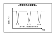
- FIG. 7 is a diagram showing an example of temporal fluctuations in direct waves received by a radio wave receiver when radio waves are emitted from a radio wave transmitter toward a rotating surface of a blade.
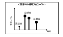
- FIG. 7 is a diagram showing an example of a delay profile of diffracted waves and reflected waves obtained when the blade is normal when radio waves are emitted from a radio wave transmitter toward the rotating surface of the blade.
- FIG. 6 is a diagram showing an example of a delay profile of diffracted waves and reflected waves obtained when a blade is damaged when a radio wave is emitted from a radio wave transmitter toward a rotating surface of the blade.
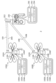
- FIG. 1 is a diagram illustrating an overview of a blade inspection system for wind power generation equipment according to an embodiment of the present disclosure.
- FIG. 1 is a block diagram showing the configuration of a blade inspection system for wind power generation equipment according to an embodiment of the present disclosure.
- 1 is a flowchart showing an operation flow of a blade inspection system for wind power generation equipment according to an embodiment of the present disclosure.
- FIG. 6 is a diagram showing an example of temporal fluctuations in the level of reflected waves received by a radio wave receiver when radio waves are emitted from a radio wave transmitter toward a rotating surface of a blade.
- 7 is a flowchart showing a processing flow of a first specific example of received signal analysis processing.
- FIG. 1 is a block diagram showing the configuration of a blade inspection system for wind power generation equipment according to an embodiment of the present disclosure.
- 1 is a flowchart showing an operation flow of a blade inspection system for wind power generation equipment according to an embodiment of the present disclosure.
- FIG. 6 is a diagram showing an example
- FIG. 6 is a diagram illustrating an example of a time variation in the phase difference between a reflected wave received by a radio wave receiver and a direct wave when a radio wave is emitted from a radio wave transmitter toward a rotating surface of a blade.
- 12 is a flowchart showing a processing flow of a second specific example of received signal analysis processing.
- FIG. 3 is a diagram showing an example of a filter that extracts delayed waves.
- FIG. 3 is a diagram illustrating a configuration of a first modification of the blade inspection system for wind power generation equipment according to an embodiment of the present disclosure.
- FIG. 7 is a diagram showing the configuration of a second modification of the blade inspection system for wind power generation equipment according to the embodiment of the present disclosure.
- the blade inspection method according to the present embodiment is carried out while the wind power generation equipment 4 is in operation, that is, while the blades 6 of the wind power generation equipment 4 are rotating.
- an unmanned aerial vehicle is used.
- the unmanned aircraft used are two drones 100A and 100B that are capable of hovering in the air.
- the drone 100A will be referred to as a first drone
- the drone 100B will be referred to as a second drone.
- the first drone 100A is equipped with a radio wave transmitter 120A.
- the second drone 100B includes a radio wave receiver 120B.
- the two drones 100A and 100B are flown near the wind power generation facility 4, and are placed at opposite positions across the blade rotation surface 8 on which the blade 6 rotates. Then, inspection radio waves are radiated toward the blade rotation surface 8 from the inspection transmission antenna 104A of the radio wave transmitter 120A mounted on the first drone 100A.
- the radio waves radiated from the radio transmitter 120A pass through the blade rotating surface 8 and reach the inspection receiving antenna 104B of the radio receiver 120B mounted on the second drone 100B.
- the radio waves radiated from the inspection transmitting antenna 104A reach the inspection receiving antenna 104B as direct waves.
- the blade 6 is rotating between the first drone 100A and the second drone 100B. Therefore, at the timing when the blade 6 directly blocks the waves, a part of the emitted radio waves is blocked by the blade 6.
- the radio waves emitted from the radio wave transmitter 120A are shielded by the blade 6, diffracted waves are generated that wrap around behind the blade 6, and these waves are received by the radio wave receiver 120B together with the direct waves.
- the diffracted waves as shown in FIG.
- the diffracted waves diffracted by the front edge of the blade 6 in the rotational direction and the diffracted waves diffracted by the rear edge of the blade 6 in the rotational direction are separately transmitted to the radio wave receiver 120B.
- the pitch angle of the blade 6 is set so that it can be rotated by the wind. Therefore, while the blade 6 is rotating, radio waves emitted from the inspection transmitting antenna 104A of the first drone 100A are reflected on the surface of the blade 6, and are received as reflected waves by the inspection receiving antenna 104B of the second drone. .
- FIG. 2 shows an example of temporal fluctuations in direct waves received by the radio receiver 120B when radio waves are emitted from the radio transmitter 120A toward the blade rotating surface 8.
- the reception level of the direct wave received by the radio wave receiver 120B decreases at regular intervals. Since the reception level decreases because the direct waves are blocked by the blade 6, the period of the reception level decrease corresponds to the rotation period of the blade 6.
- the diffracted wave and the reflected wave each reach the radio wave receiver 120B through bent paths. Therefore, the time when the diffracted wave and the reflected wave are received by the radio wave receiver 120B is delayed with respect to the time when the direct wave is received by the radio wave receiver 120B. Since the three blades 6 of the wind power generation equipment 4 have the same shape, the delay time patterns of the diffracted waves and reflected waves relative to the direct wave are almost the same among the blades 6.
- FIG. 4 shows an example of a delay profile of a diffracted wave and a reflected wave obtained when the blade 6 is damaged when a radio wave is emitted from the radio wave transmitter 120A toward the blade rotating surface 8.
- the reception level of the reflected wave received by the radio wave receiver 120B has decreased, but the phase difference between the reflected wave and the direct wave may change. Furthermore, the received level of the diffracted wave may decrease, or the phase difference between the diffracted wave and the direct wave may change. Further, depending on the damage state of the blade 6, a combination of these may occur.
- the blade inspection method according to the present embodiment focuses on this point.
- the radio wave transmitter 120A is directed toward the blade rotation surface 8.
- radio waves are emitted.
- at least one of a reflected wave and a diffracted wave generated in the blade 6 by radiation of the radio wave from the radio wave transmitter 120A is received by the radio wave receiver 120B.
- the presence or absence of an abnormality in the blade 6 is determined by analyzing the reflected wave or diffracted wave received by the radio wave receiver 120B.
- the blade 6 can be inspected without being affected by the rotational speed of the blade 6 or the weather.
- FIG. 5 is a diagram showing an overview of the blade inspection system 2 according to this embodiment.
- the blade inspection system 2 according to this embodiment includes a first drone 100A, a second drone 100B, and an investigation/inspection control device 200 that controls them.
- the first drone 100A includes a drone main body 110A having the basic structure of a drone such as a rotor, a motor, a speed controller, a flight controller, etc., and a radio wave transmitter 120A attached to the drone main body 110A.
- An antenna 102A for controlling the drone is attached to the drone body 110A.
- the first drone 100A includes therein at least a processor 190A communicably coupled to the radio wave transmitter 120A, and a memory 192A communicatively coupled to the processor 190A.
- a plurality of executable instructions 194A are stored in the memory 192A.
- Processor 190A may be a central processing unit (CPU), field programmable gate array (FPGA), application specific integrated circuit (ASIC), or another processing unit. Alternatively, processor 190A may be a combination of two or more CPUs, FPGAs, ASICs, or other processing units. Execution of instructions 194A stored in memory 192A triggers processor 190A, which may be a CPU, FPGA, ASIC, or another processing unit, to perform functions described below. Note that the memory 192A may be a separate device from the processor 190A, or may be built into the processor 190A.
- the second drone 100B includes a drone main body 110B having the basic structure of a drone such as a rotor, a motor, a speed controller, a flight controller, etc., and a radio wave receiver 120B attached to the drone main body 110B.
- An antenna 102B for controlling the drone is attached to the drone body 110B.
- the first drone 100B includes therein at least a processor 190B communicatively coupled to the radio wave receiver 120B, and a memory 192B communicatively coupled to the processor 190B.
- a plurality of executable instructions 194B are stored in the memory 192B.
- Processor 190B may be a CPU, FPGA, ASIC, or another processing unit, or a combination of two or more CPUs, FPGAs, ASICs, or other processing units.
- Memory 192B may be a separate device from processor 190B, or may be built into processor 190B.
- the investigation/inspection control device 200 is configured to operate two drones 100A, 100B and cause the drones 100A, 100B to inspect the blade 6.
- the investigation and inspection control device 200 includes an antenna 202 for controlling the drone.
- a signal line 10A for flight control and a signal line 20A for investigation and inspection control are established between the antenna 202 of the investigation and inspection control device 200 and the antenna 102A of the first drone 100A.
- a signal line 10B for flight control and a signal line 20B for investigation and inspection control are established between the antenna 202 of the investigation and inspection control device 200 and the antenna 102B of the second drone 100B.
- the investigation/inspection control device 200 includes therein a processor 290 and a memory 292 communicatively coupled to the processor 290.
- Processor 290 may be a CPU, FPGA, ASIC, or another processing unit, or a combination of two or more CPUs, FPGAs, ASICs, or other processing units.
- Memory 292 may be a separate device from processor 290 or may be built into processor 290.
- FIG. 6 is a block diagram showing the configuration of the blade inspection system 2.
- the configuration of the drone 100 and the configuration of the investigation/inspection control device 200 are represented in blocks.
- the configuration of the drone 100 shown in FIG. 6 is also the configuration of the first drone 100A and the second drone 100B.
- the first drone 100A and the second drone 100B basically have the same configuration, and the first drone 100A is used for transmitting the drone 100, and the second drone 100B is used for receiving the drone 100. It is.
- the investigation and inspection control device 200 includes an investigation and inspection control section 210, a flight control section 220, a flight control wireless transmission and reception section 230, a radio wave transmission and reception control section 240, an investigation and inspection control wireless transmission and reception section 250, and a drone control antenna 202.
- the investigation/inspection control unit 210 is also an HMI that receives operator input and provides information to the operator.
- the investigation and inspection control section 210 is coupled to a flight control section 220 and a radio wave transmission/reception control section 240. be.
- the investigation/inspection control unit 210 inputs an instruction from the operator to start inspection to the radio wave transmission/reception control unit 240. Alternatively, the investigation/inspection control unit 210 itself determines whether to start the inspection based on information regarding the flight status of the drone 100 and inputs an instruction to start the inspection to the radio wave transmission/reception control unit 240 .
- the radio wave transmission/reception control unit 240 generates an inspection command according to the instruction to start inspection.
- the inspection command generated by the radio wave transmission/reception control section 240 is outputted from the drone control antenna 202 to the investigation/inspection control signal line 20 by the investigation/inspection control radio transmission/reception section 250 .
- inspection data emitted from the drone 100 is inputted from the investigation/inspection control signal line 20 to the investigation/inspection control wireless transmitter/receiver 250 via the drone control antenna 202 .
- the radio wave transmission/reception control section 240 inputs the inspection data received by the investigation/inspection control radio transmission/reception section 250 to the investigation/inspection control section 210 .
- the investigation/inspection control unit 210 stores the input inspection data in a storage device or displays it on a display device.
- the investigation and inspection control section 210 the flight control section 220, and the radio wave transmission/reception control section 240 are realized by the processor 290.
- Each of the investigation and inspection control section 210, the flight control section 220, and the radio wave transmission/reception control section 240 may be constituted by an individual processor 290, or a plurality of them may be constituted by one processor 290.
- the processor 290 is a CPU
- the program including the instructions 294 may be provided via a network.
- the drone 100 includes a drone main body 110, a drone control antenna 102, and a battery 130.
- a flight control command issued from the investigation/inspection control device 200 is input from the flight control signal line 10 to the drone main body 110 via the drone control antenna 102.
- a flight controller configuring the drone main body 110 controls the speed controllers of each motor based on flight control instructions. Power to operate the motor is supplied from the battery 130 to the speed controller. Further, information regarding the flight status of the drone 100 issued from the flight controller is output from the drone control antenna 102 to the flight control signal line 10.
- the drone 100 further includes an investigation/inspection control wireless transmission/reception unit 140, a processing unit 150, a transmission command unit 160, a radio wave transceiver 120, an inspection transmission/reception antenna 104, a received signal analysis processing unit 170, and a storage unit 180.
- the radio wave transmitter/receiver 120 includes a radio wave transmitter 122 and a radio wave receiver 124.
- An inspection command issued from the investigation/inspection control device 200 is inputted from the investigation/inspection control signal line 20 to the investigation/inspection control wireless transmitter/receiver 140 via the drone control antenna 102 .
- the investigation/inspection control wireless transmission/reception unit 140 inputs the received command to the processing unit 150.
- the processing unit 150 operates the radio wave receiving unit 124 and the received signal analysis processing unit 170 in response to the inspection command.
- the radio wave receiving unit 124 receives radio waves input to the inspection transmitting/receiving antenna 104.
- the radio waves received by the radio wave receiving unit 124 include direct waves, diffracted waves, and reflected waves.
- the radio wave transmitter/receiver 120 functions as a radio wave receiver 120B
- the inspection transmission/reception antenna 104 functions as an inspection reception antenna 104B.
- the received signal analysis processing section 170 analyzes the received radio waves and stores the analysis results in the storage section 180.
- the storage unit 180 is, for example, a storage such as a flash memory or a hard disk.
- At least the processing section 150, the transmission command section 160, and the received signal analysis processing section 170 are realized by a processor.
- Each of the processing section 150, the transmission command section 160, and the received signal analysis processing section 170 may be composed of an individual processor, or a plurality of them may be composed of one processor.
- each of the processing unit 150 and the transmission command unit 160 is configured with an individual processor 190A, or one processor 190A configures the processing unit 150 and the transmission command unit 160. do.
- each of the processing section 150 and the received signal analysis processing section 170 is configured with an individual processor 190B, or one processor 190B is configured to combine the processing section 150 and the received signal analysis processing section. 170.
- the processors 190A and 190B are a CPU
- the program including the instructions 194A and the program including the instructions 194B may be provided via a network.
- FIG. 7 shows a flowchart showing the operation flow of the investigation/inspection control device 200 and a flowchart showing the operation flow of the drone 100, particularly the radio wave transmitter/receiver 120.
- step S201 the position information of the two drones 100A and 100B is confirmed.
- step S202 it is determined whether to start blade inspection based on the position information confirmed in step S201. Specifically, in response to confirmation that the first drone 100A and the second drone 100B are facing each other with the blade rotating surface 8 in between, it is determined that the blade inspection is to be started. This determination may be made by the investigation/inspection control unit 210, or may receive input from an operator. Whether the first drone 100A and the second drone 100B are facing each other with the blade rotation surface 8 in between can be determined from the reception state of the radio waves radiated from the first drone 100A at the second drone 100B. Further, when a camera is mounted on at least one of the two drones 100A and 100B, the positional relationship between the two with respect to the blade rotation surface 8 can be confirmed from the camera image.
- step S202 If it is determined in step S202 to start the blade inspection, an inspection command is transmitted from the investigation and inspection control device 200 to the drone 100 in step S203.
- the inspection command is simultaneously transmitted to both the first drone 100A and the second drone 100B.
- each drone 100A, 100B after receiving the inspection command will be explained.
- the two drones 100A and 100B fly to opposing positions across the blade rotation surface 8, and then hover while waiting for the start of inspection. That is, as shown in the operation flow of the drone 100, first, in step S101, each of the drones 100A and 100B is on standby for the start of inspection. Then, in step S102, it is determined whether an inspection command from the investigation/inspection control device 200 has been received.
- Each drone 100A, 100B maintains a standby state until an inspection command is received.
- step S103 If an inspection command is received in step S102, it is determined in step S103 whether to perform transmission processing or reception processing. This determination is performed in the processing section 150.
- the operation flow proceeds to step S111 to perform a transmission process.
- the operation flow from step S111 to step S114 is the operation flow of the first drone 100A.
- step S111 the radio wave transmitter 120A of the first drone 100A starts transmitting radio waves.
- step S112 it is determined whether a termination command from the investigation/inspection control device 200 has been received.
- the end command is a command for the drones 100A and 100B to end the blade inspection. Until the termination command is received, the radio wave transmitter 120A continues to transmit radio waves in step S113.
- step S103 the operation flow proceeds from step S103 to step S121 to perform reception processing.
- step S121 to step S125 is the operation flow of the second drone 100B.
- step S121 the radio wave receiver 120B of the second drone 100B starts receiving radio waves.
- step S122 an analysis process is performed on the radio waves received by the radio wave receiver 120B. Details of the received signal analysis process executed in step S122 will be described later.
- step S123 the analysis result of the received signal analysis process, that is, the inspection data indicating the blade inspection result is transmitted to the investigation/inspection control device 200. However, as the process of step S123, the analysis result may be stored in the storage unit 180 instead of transmitting the analysis result.
- step S124 it is determined whether a termination command from the investigation/inspection control device 200 has been received. The processes of step S122 and step S123 are repeated until the termination command is received.
- step S204 it is determined whether or not to end the blade inspection. This determination may be made by the investigation/inspection control unit 210, or may receive input from an operator. For example, in response to the transmission of inspection data indicating the results of blade inspection from the second drone 100B, the investigation and inspection control unit 210 may automatically end the blade inspection, or the operator may confirm the inspection data. You may complete the blade inspection. Furthermore, depending on the operator's judgment, the blade inspection may be forcibly terminated before inspection data is obtained.
- step S205 it is determined whether or not to save the inspection data transmitted from the second drone 100B. If the determination in step S205 is affirmative, the inspection data is stored in the storage included in the investigation/inspection control device 200 in step S206. Whether or not to save inspection data can be arbitrarily determined. For example, as a result of checking the inspection data, if it can be determined that there is no obvious abnormality in the blade 6, the inspection data may not be saved. On the other hand, if it can be determined that there is a possibility of an abnormality in the blade 6, the inspection data may be saved.
- step S207 after determining whether to save the inspection data, a termination command is sent from the investigation and inspection control device 200 to both the first drone 100A and the second drone 100B. Then, in response to the transmission of the termination command, the blade inspection is terminated in step S208.
- step S112 In response to the first drone 100A receiving the termination command transmitted from the investigation and inspection control device 200, the determination in step S112 changes from negative to positive. Thereby, in step S114, the transmission of radio waves by the radio wave transmitter 120A is ended.
- step S124 changes from negative to positive.
- step S125 the radio wave reception by the radio wave receiver 120B and the analysis process by the received signal analysis processing section 170 are completed.
- Received signal analysis processing 4-1 First Specific Example Next, a received signal analysis process executed by the received signal analysis processing unit 170 when the drone 100 functions as the second drone 100B will be specifically described.
- the received signal analysis process is an analysis process performed on reflected waves or diffracted waves in order to determine whether there is an abnormality in the blade 6 from the radio waves received by the radio wave receiver 120B.
- analysis processing for reflected waves particularly analysis processing based on the reception level of reflected waves, will be explained.
- FIG. 8 is a diagram illustrating an example of temporal fluctuations in the level of reflected waves received by the radio receiver 120B when radio waves are emitted from the radio transmitter 120A toward the blade rotating surface 8.
- the reflected wave from the second blade exhibits a different profile from the reflected waves from the first blade and the third blade.
- a large variation occurs only in the reception level of the second blade.
- the presence or absence of an abnormality in the blade 6 is determined by detecting such abnormal fluctuations in the reception level.
- FIG. 9 is a flowchart showing the processing flow of the first specific example of received signal analysis processing.
- step S301 the delay profile of radio waves received by the radio wave receiver 120B is measured. Further, in step S302, a counter ⁇ for determining the end of the measurement section shown in FIG. 8 is initialized.
- step S303 reflected waves are extracted from the delay profile measured in step S301.
- a specific example of the reflected wave extraction method will be described later.
- step S304 it is determined whether the received level of the extracted reflected wave has become larger than a threshold value.
- the threshold value used in step S304 is a threshold value for detecting the rise of the reflected wave. Steps S303 and S304 are repeated until the received level of the reflected wave becomes greater than the threshold value.
- the reception level of the reflected wave becoming larger than the threshold value means the start of the measurement period.
- step S305 data on the reception level of the reflected wave for each time is accumulated.
- step S306 it is determined whether the received level of the extracted reflected wave remains higher than the threshold value.
- the threshold value used in step S306 is a threshold value for detecting the falling edge of the reflected wave. This threshold value may be the same value as the threshold value used in step S304. Steps S305 and S306 are repeated until the received level of the reflected wave becomes equal to or less than the threshold value.
- the cases where the received level of the reflected wave falls below the threshold are the case where the blade passes and the measurement section ends, and the case where the received level of the reflected wave fluctuates due to damage to the blade. be.
- the reception level continues to be below the threshold, whereas in the latter case, the decrease in the reception level is temporary. Therefore, in order to distinguish between the two, the period of time that has elapsed since the received level of the reflected wave became equal to or less than the threshold is measured.
- the parameter used to measure the elapsed time is the counter initialized in step S302.
- Steps S305 to S309 are repeated until the counter ⁇ exceeds the predetermined time T as determined in step S307. Then, when the counter ⁇ exceeds the predetermined time T, it is determined that the reflected wave measurement period has ended, and the process flow exits the loop of steps S305 to S309 and proceeds to step S310.
- step S310 it is determined whether the variation in the received level data accumulated during the measurement period is large. Specifically, it is determined whether the variance or standard deviation of the accumulated reception level data is larger than a predetermined reference value.
- Fluctuations in the reception level data accumulated during a measurement period indicate the presence or absence of an abnormality in the blade corresponding to that measurement period. If the fluctuation in the reception level data is large, it is determined in step S311 that the blade corresponding to the measurement section is damaged. If the fluctuation in the reception level data is not large, it is determined in step S312 that there is no abnormality in the blade corresponding to the measurement section.
- the first specific example of the received signal analysis process having the above processing flow can also be applied to analysis process based on the reception level of a diffracted wave.
- FIG. 10 is a diagram illustrating an example of temporal fluctuations in the phase difference between the reflected wave and the direct wave received by the radio receiver 120B when radio waves are emitted from the radio transmitter 120A toward the blade rotating surface 8.
- the reflected wave from the second blade exhibits a different profile from the reflected waves from the first blade and the third blade.
- a large variation occurs in the phase difference between the reflected wave and the direct wave only in the second blade.
- the presence or absence of an abnormality in the blade 6 is determined by detecting abnormal fluctuations in the phase difference of the reflected wave with respect to the direct wave.
- FIG. 11 is a flowchart showing the processing flow of a second specific example of received signal analysis processing.
- step S401 the delay profile of radio waves received by the radio wave receiver 120B is measured.
- step S402 reflected waves are extracted from the delay profile measured in step S401. A specific example of the reflected wave extraction method will be described later.
- step S403 it is determined whether the reception level of the extracted reflected wave has become larger than a threshold value.
- the threshold value used in step S403 is a threshold value for detecting the rise of the reflected wave. Steps S402 and S403 are repeated until the received level of the reflected wave becomes greater than the threshold.
- the reception level of the reflected wave becoming larger than the threshold value means the start of the measurement period.
- step S404 the phase difference between the reflected wave and the direct wave is measured.
- step S405 data on the phase difference measured in step S404 is accumulated.
- step S406 it is determined whether the received level of the extracted reflected wave remains higher than the threshold value.
- the threshold value used in step S406 is a threshold value for detecting the falling edge of the reflected wave. This threshold value may be the same value as the threshold value used in step S403. Steps S404 to S406 are repeated until the reception level of the reflected wave becomes equal to or less than the threshold value.
- step S407 it is determined whether the fluctuation in the phase difference data accumulated during the measurement period is large. Specifically, it is determined whether the variance or standard deviation of the accumulated phase difference data is larger than a predetermined reference value.
- Fluctuations in the phase difference data accumulated during a measurement period represent the presence or absence of an abnormality in the blade corresponding to that measurement period. If the fluctuation in the reception level data is large, it is determined in step S408 that the blade corresponding to the measurement section is damaged. If the fluctuation in the reception level data is not large, it is determined in step S409 that there is no abnormality in the blade corresponding to the measurement section.
- the second specific example of the received signal analysis process having the above processing flow can also be applied to an analysis process based on the phase difference of a diffracted wave with respect to a direct wave. Further, it is also possible to use the first specific example and the second specific example of the received signal analysis processing in combination to determine whether there is an abnormality in the blade.
- FIG. 12 shows a filter configured to extract the first wave, a filter configured to extract the second wave, a filter configured to extract the third wave, and a filter configured to extract the fourth wave. A filter configured to do so is depicted.
- FIG. 12 illustrates delay profiles from the first wave to the fourth wave.
- the reception level h 1 of the first wave, the reception level h 2 of the second wave, the reception level h 3 of the third wave, and the reception level h 4 of the fourth wave shown in the delay profile are each measured values under normal conditions.
- the delay time ⁇ 1 of the second wave with respect to the first wave, the delay time ⁇ 2 of the third wave with respect to the second wave, and the delay time ⁇ 3 of the fourth wave with respect to the third wave shown in the delay profile are also normal. This is a measured value.
- Each filter is created using these values.
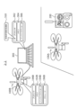
- FIG. 13 is a diagram showing the configuration of a first modification of the blade inspection system according to the present embodiment.
- the blade inspection system 2-1 of the first modification includes a first drone 100A equipped with a radio wave transmitter 120A, a second drone 100B equipped with a radio wave receiver 120B, an investigation inspection control device 200, and an analysis computer 300.
- Analysis computer 300 includes therein a processor 302 and a memory 304 communicatively coupled to processor 302. A plurality of executable instructions 306 are stored in the memory 304.
- the analysis computer 300 is connected to the investigation and inspection control device 200.
- the second drone 100B does not include a received signal analysis processing unit. Therefore, the received signal analysis process for determining whether there is an abnormality in the blade 6 is not performed in the second drone 100B.
- the second drone 100B transfers received data including direct waves, diffracted waves, and reflected waves received by the radio wave receiver 120B to the investigation/inspection control device 200.
- the investigation and inspection control device 200 transfers the received data transmitted from the second drone 100B to the analysis computer 300.
- the analysis computer 300 at least a portion of the plurality of instructions 306 are executed by the processor 302, so that the processor 302 functions as a received signal analysis processing section 310. That is, in the blade inspection system 2-1 of the first modification, the received signal analysis process is performed by the analysis computer 300.
- FIG. 14 is a diagram showing the configuration of a second modified example of the blade inspection system according to the present embodiment.
- a blade inspection system 2-2 as a second modification includes a first drone 100A equipped with a radio wave transmitter 120A, a second drone 100B equipped with a radio wave receiver 120B, an investigation inspection control device 200, and an analysis computer 300.
- Analysis computer 300 includes therein a processor 302 and a memory 304 communicatively coupled to processor 302.
- a plurality of executable instructions 306 are stored in the memory 304.
- the second drone 100B does not include a received signal analysis processing unit. Therefore, the received signal analysis process for determining whether there is an abnormality in the blade 6 is not performed in the second drone 100B.
- the second drone 100B stores received data including direct waves, diffracted waves, and reflected waves received by the radio wave receiver 120B in the storage 196B.
- the received data stored in the storage 196B of the second drone 100B can be transferred from the storage 196B to the analysis computer 300 by connecting the second drone 100B and the analysis computer 300. Further, if the storage 196B is a memory card, for example, the received data can be transferred to the analysis computer 300 by transferring the memory card from the second drone 100B to the analysis computer 300.
- the analysis computer 300 at least a portion of the plurality of instructions 306 are executed by the processor 302, so that the processor 302 functions as a received signal analysis processing section 310. That is, in the blade inspection system 2-2 of the second modification, the received signal analysis process is performed by the analysis computer 300.
- radio waves are used for blade inspection in the above embodiments, electromagnetic waves can be used for blade inspection as long as reflected waves or diffracted waves can be obtained.
- two drones 100A and 100B are operated by one investigation and inspection control device 200, but the investigation and inspection control device controls the first drone 100A and the second drone 100B. It may be a device different from the control device.
Landscapes
- Engineering & Computer Science (AREA)
- Chemical & Material Sciences (AREA)
- Life Sciences & Earth Sciences (AREA)
- Physics & Mathematics (AREA)
- Sustainable Energy (AREA)
- Combustion & Propulsion (AREA)
- Mechanical Engineering (AREA)
- General Engineering & Computer Science (AREA)
- Sustainable Development (AREA)
- Health & Medical Sciences (AREA)
- Electromagnetism (AREA)
- Analytical Chemistry (AREA)
- Biochemistry (AREA)
- General Health & Medical Sciences (AREA)
- General Physics & Mathematics (AREA)
- Immunology (AREA)
- Pathology (AREA)
- Radar Systems Or Details Thereof (AREA)
- Wind Motors (AREA)
Abstract
Description
以下、図を参照して本開示の実施形態に係る風力発電設備のブレードを点検するシステムと、そのシステムで実行される方法について説明する。以下、風力発電設備のブレードを点検するシステムをブレード点検システムと呼び、ブレード点検システムで実行される方法をブレード点検方法と呼ぶ。
次に、上記のブレード点検方法が実施されるブレード点検システムについて説明する。図5は本実施形態に係るブレード点検システム2の概要を示す図である。本実施形態に係るブレード点検システム2は、第1ドローン100A及び第2ドローン100Bと、それらを制御する調査点検制御装置200とを含む。
ある。
次に、上記のように構成されたブレード点検システム2の動作についてフローチャートを用いて説明する。図7には、調査点検制御装置200の動作フローを示すフローチャートと、ドローン100、特に、電波送受信機120の動作フローを示すフローチャートとが併せて示されている。
4-1.第1具体例
次に、ドローン100が第2ドローン100Bとして機能する場合に受信信号解析処理部170で実行される受信信号解析処理について具体的に説明する。受信信号解析処理は、電波受信機120Bで受信された電波からブレード6の異常の有無を判定するために反射波又は回折波に対して行われる解析処理である。ここでは反射波に対する解析処理、特に、反射波の受信レベルに基づく解析処理について説明する。
次に、受信信号解析処理部170で実行される受信信号解析処理の第2具体例について説明する。ここでは反射波に対する解析処理、特に、反射波の直接波に対する位相差に基づく解析処理について説明する。
電波受信機120Bによって受信された電波から回折波と反射波を抽出する手段として、例えば、図12に示されるトランスバーサルフィルタを用いることができる。図12には、第1波を抽出するように構成されたフィルタ、第2波を抽出するように構成されたフィルタ、第3波を抽出するように構成されたフィルタ、及び第4波を抽出するように構成されたフィルタが描かれている。
6-1.第1変形例
最後に、本実施形態に係るブレード点検システムの変形例について図を用いて説明する。変形例を示す図において、ブレード点検システム2と共通の要素には共通の符号が付されている。
図14は本実施形態に係るブレード点検システムの第2変形例の構成を示す図である。第2変形例としてのブレード点検システム2-2は、電波送信機120Aを備える第1ドローン100A、電波受信機120Bを備える第2ドローン100B、調査点検制御装置200、及び解析用コンピュータ300を備える。解析用コンピュータ300は、その内部に、プロセッサ302とプロセッサ302に通信可能に結合されたメモリ304とを備える。メモリ304には実行可能な複数のインストラクション306が記憶されている。
上記の実施形態ではブレード点検に電波が用いられているが、反射波又は回折波が得られる限りにおいてブレード点検には電磁波を用いることができる。
4 風力発電設備
6 ブレード
8 ブレード回転面
100 ドローン(無人航空機)
100A 第1ドローン(第1無人航空機)
100B 第2ドローン(第2無人航空機)
120 電波送受信機
120A 電波送信機
120B 電波受信機
170、310 受信信号解析処理部
190A、190B、290、302 プロセッサ
192A、192B、292、304 メモリ
194A、194B、294、306 インストラクション
200 調査点検制御装置
300 解析用コンピュータ
Claims (7)
- 風力発電設備のブレードを点検するシステムであって、
第1無人航空機に搭載された電磁波の送信機と、
第2無人航空機に搭載された電磁波の受信機と、
前記送信機と前記受信機とに通信可能に結合された少なくとも1つのプロセッサと、
前記少なくとも1つのプロセッサと通信可能に結合された、実行可能な複数のインストラクションを記憶したメモリと、を備え、
前記複数のインストラクションは、前記少なくとも1つのプロセッサに、
前記第1無人航空機と前記第2無人航空機とが前記ブレードの回転面を挟んで相対している状態で前記送信機から前記回転面に向けて電磁波を放射することと、
前記送信機からの電磁波の放射によって前記ブレードにおいて生じた反射波と回折波の少なくとも一方を前記受信機で受信することと、
前記受信機で受信された反射波又は回折波の解析処理によって前記ブレードの異常の有無を判定することと、を実行させるように構成されている
ことを特徴とするシステム。 - 請求項1に記載のシステムにおいて、
前記解析処理によって前記ブレードの異常の有無を判定することは、前記受信機で受信された反射波又は回折波の受信レベルの変動状態に基づいて異常の有るブレードと異常の無いブレードとを区別することを含む
ことを特徴とするシステム。 - 請求項1に記載のシステムにおいて、
前記解析処理によって前記ブレードの異常の有無を判定することは、前記受信機で受信された反射波又は回折波の直接波に対する位相差の変動状態に基づいて異常の有るブレードと異常の無いブレードとを区別することを含む
ことを特徴とするシステム。 - 風力発電設備のブレードを点検する方法であって、
電磁波の送信機が搭載された第1無人航空機を前記ブレードの回転面の周辺で待機させることと、
電磁波の受信機が搭載された第2無人航空機を前記回転面の周辺で待機させることと、
前記第1無人航空機と前記第2無人航空機とが前記回転面を挟んで相対している状態で前記送信機から前記回転面に向けて電磁波を放射することと、
前記送信機からの電磁波の放射によって前記ブレードにおいて生じた反射波と回折波の少なくとも一方を前記受信機で受信することと、
前記受信機で受信された反射波又は回折波の解析処理によって前記ブレードの異常の有無を判定することと、を含む
ことを特徴とする方法。 - 請求項4に記載の方法において、
前記解析処理によって前記ブレードの異常の有無を判定することは、前記受信機で受信された反射波又は回折波の受信レベルの変動状態に基づいて異常の有るブレードと異常の無いブレードとを区別することを含む
ことを特徴とする方法。 - 請求項4に記載の方法において、
前記解析処理によって前記ブレードの異常の有無を判定することは、前記受信機で受信された反射波又は回折波の直接波に対する位相差の変動状態に基づいて異常の有るブレードと異常の無いブレードとを区別することを含む
ことを特徴とする方法。 - 風力発電設備のブレードを点検する装置であって、
アンテナと、
前記アンテナが前記ブレードの回転面を挟んで電磁波の送信機と相対している場合に、前記送信機からの電磁波の放射によって前記ブレードにおいて生じた反射波と回折波の少なくとも一方を前記アンテナを用いて受信するように構成された受信部と、
前記受信部で受信された反射波又は回折波の解析処理によって前記ブレードの異常の有無を判定するように構成された解析処理部と、を備える
ことを特徴とする装置。
Priority Applications (3)
| Application Number | Priority Date | Filing Date | Title |
|---|---|---|---|
| PCT/JP2022/026600 WO2024009356A1 (ja) | 2022-07-04 | 2022-07-04 | 風力発電設備のブレードを点検するシステム、方法、及び装置 |
| US18/875,184 US20250369901A1 (en) | 2022-07-04 | 2022-07-04 | System, method and device for checking blades of wind power plant |
| JP2024531765A JP7831601B2 (ja) | 2022-07-04 | 2022-07-04 | 風力発電設備のブレードを点検するシステム、方法、及び装置 |
Applications Claiming Priority (1)
| Application Number | Priority Date | Filing Date | Title |
|---|---|---|---|
| PCT/JP2022/026600 WO2024009356A1 (ja) | 2022-07-04 | 2022-07-04 | 風力発電設備のブレードを点検するシステム、方法、及び装置 |
Publications (1)
| Publication Number | Publication Date |
|---|---|
| WO2024009356A1 true WO2024009356A1 (ja) | 2024-01-11 |
Family
ID=89452928
Family Applications (1)
| Application Number | Title | Priority Date | Filing Date |
|---|---|---|---|
| PCT/JP2022/026600 Ceased WO2024009356A1 (ja) | 2022-07-04 | 2022-07-04 | 風力発電設備のブレードを点検するシステム、方法、及び装置 |
Country Status (3)
| Country | Link |
|---|---|
| US (1) | US20250369901A1 (ja) |
| JP (1) | JP7831601B2 (ja) |
| WO (1) | WO2024009356A1 (ja) |
Citations (3)
| Publication number | Priority date | Publication date | Assignee | Title |
|---|---|---|---|---|
| US20050264275A1 (en) * | 2004-05-27 | 2005-12-01 | Thomas Bosselmann | Doppler radar sensing system for monitoring turbine generator components |
| JP2019027908A (ja) * | 2017-07-28 | 2019-02-21 | 株式会社TonTon | 外面材調査システム |
| JP2020118141A (ja) * | 2019-01-28 | 2020-08-06 | 株式会社日立製作所 | 風力発電装置のブレード点検システム、風力発電システム、ウィンドファームの遠隔統合監視システム |
-
2022
- 2022-07-04 JP JP2024531765A patent/JP7831601B2/ja active Active
- 2022-07-04 US US18/875,184 patent/US20250369901A1/en active Pending
- 2022-07-04 WO PCT/JP2022/026600 patent/WO2024009356A1/ja not_active Ceased
Patent Citations (3)
| Publication number | Priority date | Publication date | Assignee | Title |
|---|---|---|---|---|
| US20050264275A1 (en) * | 2004-05-27 | 2005-12-01 | Thomas Bosselmann | Doppler radar sensing system for monitoring turbine generator components |
| JP2019027908A (ja) * | 2017-07-28 | 2019-02-21 | 株式会社TonTon | 外面材調査システム |
| JP2020118141A (ja) * | 2019-01-28 | 2020-08-06 | 株式会社日立製作所 | 風力発電装置のブレード点検システム、風力発電システム、ウィンドファームの遠隔統合監視システム |
Also Published As
| Publication number | Publication date |
|---|---|
| US20250369901A1 (en) | 2025-12-04 |
| JPWO2024009356A1 (ja) | 2024-01-11 |
| JP7831601B2 (ja) | 2026-03-17 |
Similar Documents
| Publication | Publication Date | Title |
|---|---|---|
| US10429511B2 (en) | Light detection and ranging (LIDAR) ice detection system | |
| US20220005361A1 (en) | Fleet management of unmanned aerial vehicles and flight authorization system | |
| DK3077669T3 (en) | Method of optically obtaining information using an aircraft | |
| US10173776B2 (en) | Aerial drone for deploying a warning sign | |
| EP2772439B1 (en) | Identification of aircraft surface positions using camera images | |
| US20090076728A1 (en) | Aircraft terrain avoidance and alarm method and device | |
| CN113376581A (zh) | 雷达遮挡物检测方法及装置 | |
| JP6980037B2 (ja) | 情報処理装置 | |
| EP3651139B1 (en) | Methods and systems for relevance determination of shared environmental data based on vehicle context | |
| CN115755946A (zh) | 一种基于数字孪生的电力巡检方法、装置及系统 | |
| KR20200142142A (ko) | 고압 송전탑 안전 점검 방법 및 이를 실행하기 위하여 기록매체에 기록된 컴퓨터 프로그램 | |
| CN114511675B (zh) | 一种基于实景三维数据制作的无人机摄像管控系统 | |
| WO2020082364A1 (zh) | 无人机的控制方法、装置、无人机及计算机可读存储介质 | |
| WO2024009356A1 (ja) | 風力発電設備のブレードを点検するシステム、方法、及び装置 | |
| CN115063953A (zh) | 输电线路智能防护预警方法、装置、系统以及电子设备 | |
| EP3460488B1 (en) | Automatic gain control for laser detector | |
| CN119062529B (zh) | 风机叶片状态的检测方法及装置 | |
| CN112180353A (zh) | 目标对象的确认方法及系统、存储介质 | |
| CN119846071A (zh) | 基于无人机的高层双曲玻璃幕墙自动巡检方法以及系统 | |
| GB2580639A (en) | System and method for inspecting a moving structure | |
| CN108733071A (zh) | 用于将飞行参数从引领飞行器传输至闯入飞行器的方法 | |
| KR102538948B1 (ko) | 스테이션에 이착륙하는 무인 비행체를 점검하기 위한 제어 장치 및 그 방법 | |
| CN116382318A (zh) | 巡检无人机及其避障装置 | |
| CN113110579B (zh) | 基于热辐射的无人机巡检方法、装置、无人机及存储介质 | |
| JP7574935B2 (ja) | 不審機対処装置、不審機対処システム、不審機対処方法およびコンピュータプログラム |
Legal Events
| Date | Code | Title | Description |
|---|---|---|---|
| 121 | Ep: the epo has been informed by wipo that ep was designated in this application |
Ref document number: 22950151 Country of ref document: EP Kind code of ref document: A1 |
|
| WWE | Wipo information: entry into national phase |
Ref document number: 2024531765 Country of ref document: JP |
|
| WWE | Wipo information: entry into national phase |
Ref document number: 18875184 Country of ref document: US |
|
| NENP | Non-entry into the national phase |
Ref country code: DE |
|
| 122 | Ep: pct application non-entry in european phase |
Ref document number: 22950151 Country of ref document: EP Kind code of ref document: A1 |
|
| WWP | Wipo information: published in national office |
Ref document number: 18875184 Country of ref document: US |