WO2024004535A1 - コントロール弁のシートリーク検知方法 - Google Patents
コントロール弁のシートリーク検知方法 Download PDFInfo
- Publication number
- WO2024004535A1 WO2024004535A1 PCT/JP2023/020791 JP2023020791W WO2024004535A1 WO 2024004535 A1 WO2024004535 A1 WO 2024004535A1 JP 2023020791 W JP2023020791 W JP 2023020791W WO 2024004535 A1 WO2024004535 A1 WO 2024004535A1
- Authority
- WO
- WIPO (PCT)
- Prior art keywords
- pressure
- downstream
- flow rate
- time
- upstream
- Prior art date
Links
- 238000001514 detection method Methods 0.000 title claims abstract description 59
- 238000011144 upstream manufacturing Methods 0.000 claims abstract description 95
- 238000012544 monitoring process Methods 0.000 claims abstract description 6
- 238000007689 inspection Methods 0.000 claims description 32
- 238000000034 method Methods 0.000 claims description 27
- 239000012530 fluid Substances 0.000 claims description 17
- 238000005259 measurement Methods 0.000 claims description 10
- 239000007789 gas Substances 0.000 description 36
- 230000008569 process Effects 0.000 description 16
- 238000012360 testing method Methods 0.000 description 15
- 230000000052 comparative effect Effects 0.000 description 11
- 238000009530 blood pressure measurement Methods 0.000 description 7
- 238000010586 diagram Methods 0.000 description 7
- 230000007423 decrease Effects 0.000 description 5
- 239000002184 metal Substances 0.000 description 4
- 230000008859 change Effects 0.000 description 3
- 230000014509 gene expression Effects 0.000 description 3
- 238000004519 manufacturing process Methods 0.000 description 3
- 239000011347 resin Substances 0.000 description 3
- 229920005989 resin Polymers 0.000 description 3
- 239000004065 semiconductor Substances 0.000 description 3
- 230000006641 stabilisation Effects 0.000 description 3
- 238000011105 stabilization Methods 0.000 description 3
- XKRFYHLGVUSROY-UHFFFAOYSA-N Argon Chemical compound [Ar] XKRFYHLGVUSROY-UHFFFAOYSA-N 0.000 description 2
- 238000005530 etching Methods 0.000 description 2
- 230000007246 mechanism Effects 0.000 description 2
- 230000004043 responsiveness Effects 0.000 description 2
- 230000007704 transition Effects 0.000 description 2
- XUIMIQQOPSSXEZ-UHFFFAOYSA-N Silicon Chemical compound [Si] XUIMIQQOPSSXEZ-UHFFFAOYSA-N 0.000 description 1
- 230000004913 activation Effects 0.000 description 1
- 230000032683 aging Effects 0.000 description 1
- 229910052786 argon Inorganic materials 0.000 description 1
- 239000012159 carrier gas Substances 0.000 description 1
- 238000004590 computer program Methods 0.000 description 1
- 230000007797 corrosion Effects 0.000 description 1
- 238000005260 corrosion Methods 0.000 description 1
- 239000013078 crystal Substances 0.000 description 1
- 230000002950 deficient Effects 0.000 description 1
- 230000006866 deterioration Effects 0.000 description 1
- 238000011161 development Methods 0.000 description 1
- 230000018109 developmental process Effects 0.000 description 1
- 238000007865 diluting Methods 0.000 description 1
- 230000000694 effects Effects 0.000 description 1
- 238000012423 maintenance Methods 0.000 description 1
- 230000007257 malfunction Effects 0.000 description 1
- 238000012986 modification Methods 0.000 description 1
- 230000004048 modification Effects 0.000 description 1
- 229920002493 poly(chlorotrifluoroethylene) Polymers 0.000 description 1
- -1 polychlorotrifluoroethylene Polymers 0.000 description 1
- 239000005023 polychlorotrifluoroethylene (PCTFE) polymer Substances 0.000 description 1
- 239000002994 raw material Substances 0.000 description 1
- 230000009467 reduction Effects 0.000 description 1
- 238000007789 sealing Methods 0.000 description 1
- 229910052710 silicon Inorganic materials 0.000 description 1
- 239000010703 silicon Substances 0.000 description 1
- 239000000126 substance Substances 0.000 description 1
- 230000002123 temporal effect Effects 0.000 description 1
- 239000010409 thin film Substances 0.000 description 1
Images


Classifications
-
- F—MECHANICAL ENGINEERING; LIGHTING; HEATING; WEAPONS; BLASTING
- F16—ENGINEERING ELEMENTS AND UNITS; GENERAL MEASURES FOR PRODUCING AND MAINTAINING EFFECTIVE FUNCTIONING OF MACHINES OR INSTALLATIONS; THERMAL INSULATION IN GENERAL
- F16K—VALVES; TAPS; COCKS; ACTUATING-FLOATS; DEVICES FOR VENTING OR AERATING
- F16K51/00—Other details not peculiar to particular types of valves or cut-off apparatus
-
- G—PHYSICS
- G01—MEASURING; TESTING
- G01M—TESTING STATIC OR DYNAMIC BALANCE OF MACHINES OR STRUCTURES; TESTING OF STRUCTURES OR APPARATUS, NOT OTHERWISE PROVIDED FOR
- G01M3/00—Investigating fluid-tightness of structures
- G01M3/02—Investigating fluid-tightness of structures by using fluid or vacuum
- G01M3/26—Investigating fluid-tightness of structures by using fluid or vacuum by measuring rate of loss or gain of fluid, e.g. by pressure-responsive devices, by flow detectors
- G01M3/28—Investigating fluid-tightness of structures by using fluid or vacuum by measuring rate of loss or gain of fluid, e.g. by pressure-responsive devices, by flow detectors for pipes, cables or tubes; for pipe joints or seals; for valves ; for welds
-
- G—PHYSICS
- G05—CONTROLLING; REGULATING
- G05D—SYSTEMS FOR CONTROLLING OR REGULATING NON-ELECTRIC VARIABLES
- G05D7/00—Control of flow
- G05D7/06—Control of flow characterised by the use of electric means
Definitions
- the present invention relates to a seat leak detection method for a control valve included in a flow rate control device.
- Pressure flow control devices are widely used because they can control the mass flow rate of various fluids with high precision using a relatively simple configuration that combines a control valve and a restrictor (for example, an orifice plate or critical nozzle). .
- the pressure-type flow rate control device has excellent flow rate control characteristics that allow stable flow rate control even when the supply pressure on the primary side varies greatly.
- Some pressure-type flow rate control devices adjust the flow rate by controlling the fluid pressure on the upstream side of the constriction portion (hereinafter sometimes referred to as upstream pressure P1).
- upstream pressure P1 is controlled by adjusting the opening degree of a control valve disposed in the flow path upstream of the throttle section.
- control valve for example, a piezo element-driven valve configured to open and close a diaphragm valve body using a piezo actuator is used.
- the piezo element-driven valve has high responsiveness, and by feedback-controlling it based on the upstream pressure P1, it is possible to appropriately control the flow rate of gas flowing downstream of the throttle section.
- each parallel flow path branching from the upstream flow path is provided with a restrictor and a control valve is underway (e.g. , Patent Document 1).
- the parallel flow path is provided with a constriction section for large flow rate and a constriction section for small flow rate, and by controlling the opening and closing of the parallel flow path, gas can be supplied by switching between the high flow rate range and the small flow rate range. Can be done.
- valve seat the adhesion between the diaphragm valve element and the seat (valve seat) may not be perfect, and in this case, seat leak (the contact between the valve element and the seat when the valve is closed) leakage from the gaps between the parts may occur. Even if seat leakage does not occur at the initial stage of use of the device, it may occur due to aging as the valve is opened and closed many times. Further, seat leakage may occur or increase as the device is used, due to gas deposits on the valve body and valve seat, or deterioration or deformation due to corrosion.
- Patent Document 2 by the applicant of the present application discloses a method of detecting seat leak of a control valve provided in a parallel flow path.
- the upstream on-off valve provided in the common flow path on the upstream side of the parallel flow paths and the downstream on-off valve provided in the common flow path on the downstream side of the parallel flow paths are closed to create a sealed space including the parallel flow paths. is formed.
- the control valves provided in each parallel flow path are also closed at the same time.
- the present invention has been made to solve the above problems, and its main purpose is to provide a method for more accurately detecting seat leak in a control valve that constitutes a flow rate control device while preventing false detection. shall be.
- a seat leak detection method includes a constriction section, a control valve provided upstream of the constriction section, and a first control valve provided between the control valve and the constriction section that measures upstream pressure.
- a control flow path having a pressure sensor; a second pressure sensor provided downstream of the constriction portion to measure downstream pressure; and an inflow pressure sensor provided upstream of the control valve to measure supply pressure.
- the supply pressure is Step (a) of closing the upstream on-off valve and the downstream on-off valve and inputting a set flow rate of 0% or the control valve forced close signal to the flow rate control device in a state that is greater than the downstream pressure; After a), at a first time, at least one of the inflow pressure sensor, the first pressure sensor, and the second pressure sensor is used to measure the supply pressure, the upstream pressure, and the downstream pressure.
- step (b) measuring at least one of the supply pressure, the upstream pressure, and the downstream pressure at a second time after the first time; and the control based on the pressure fluctuation of at least one of the supply pressure, the upstream pressure, and the downstream pressure measured in the step (b) and the step (c).
- a step (d) of detecting a seat leak of the valve and the step (d) includes detecting the supply pressure, the upstream pressure, and the downstream pressure at the first time and the second time. If at least one of the pressure fluctuations exceeds the threshold, an input other than the set flow rate of 0% or a signal other than the control valve forced close signal is input as the set flow rate from the second time to the third time thereafter.
- a plurality of control channels are provided in parallel between a common inflow channel and a common outflow channel.
- the supply pressure and the downstream pressure are measured at the first time, the second time, and the third time, and pressure fluctuations in the supply pressure and the downstream pressure are measured. Seat leaks are detected based on both pressure fluctuations.
- the seat leak detection method further includes the step of issuing an alarm when the seat leak is detected.
- the step (d) includes the measurement result of at least one of the supply pressure, the upstream pressure, and the downstream pressure at the third time, and the measurement result at the first time.
- the method includes detecting a seat leak based on a pressure fluctuation determined from a measurement result of at least one of the supply pressure, the upstream pressure, and the downstream pressure.
- the step (d) is performed based on the pressure fluctuation of at least one of the supply pressure, the upstream pressure, and the downstream pressure measured in the step (b) and the step (c). ), when it is determined that no seat leak has occurred, the supply pressure, the upstream pressure, and The test is repeated by measuring at least one of said downstream pressures while the set flow rate is maintained at 0%.
- FIG. 7 is a diagram for explaining a more specific aspect of a seat leak detection method of a comparative example.
- FIG. 6 is a diagram for explaining the operation of false detection that may occur in a seat leak detection method of a comparative example.
- 1 is a diagram schematically showing a fluid system including a flow rate control device according to an embodiment of the present invention.
- 1 is a diagram schematically showing a flow rate control device according to an embodiment of the present invention.
- 3 is a flowchart of an improved seat leak detection method according to an embodiment of the present invention.
- FIG. 1 shows the configuration of a flow rate control device 90 as a comparative example.
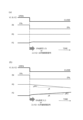
- FIGS. 2(a) and 2(b) show the opening/closing operation of each valve and the temporal changes in the supply pressure P0 and the downstream pressure P2 in the seat leak detection process.
- FIG. 2(a) shows a case where no seat leak occurs
- FIG. 2(b) shows a case where seat leak occurs.
- the flow rate control device 90 has a common inflow path 91 and a common outflow path 92, and a parallel flow path is provided between the common inflow path 91 and the common outflow path 92.
- a first flow path 93a and a second flow path 93b are provided.
- Each parallel flow path 93a, 93b is provided with a control valve 94a, 94b, a first pressure sensor 95a, 95b, and a throttle section 96a, 96b, respectively.
- the common inflow path 91 is provided with an inflow pressure sensor 97 that measures the supply pressure P0 upstream of the control valves 94a, 94b, and the common outflow path 92 is provided with a downstream pressure P0 downstream of the throttle portions 96a, 96b.
- a second pressure sensor 98 is provided to measure P2.
- the opening degree of the control valve 94a is adjusted based on the output (upstream pressure P1) of the first pressure sensor 95a with the control valve 94b of the second flow path 93b completely closed.
- Gas can be supplied at a controlled flow rate in a large flow rate range through a relatively large-diameter constriction portion 96a provided in the first flow path 93a.
- the second flow path Gas can be supplied at a controlled flow rate in a small flow rate range through a relatively small-diameter constriction portion 96b provided at 93b.
- an upstream on-off valve V1 is provided on the upstream side of the flow rate control device 90
- a downstream on-off valve V2 is provided on the downstream side of the flow rate control device 90.
- the fluid system including the flow control device 90 is configured such that the flow path can be blocked both upstream and downstream of the flow control device 90.
- seat leak detection of the control valves 94a and 94b is performed by simultaneously closing the upstream on-off valve V1 and the downstream on-off valve V2, and closing the control valve V1 and the downstream on-off valve V2, as shown in FIGS. Close one of the open sides of 94a and 94b (change the set flow rate input IN from arbitrary X% to 0%, or input a forced close signal to the control valves 94a and 94b) It is done by Hereinafter, in this specification, a description regarding the forced closing signal for the control valves 94a and 94b will be omitted, and a configuration in which the set flow rate is 0% will be described.
- the flow rate control device 90 can perform the seat leak detection process at a timing when the controlled flow rate becomes 0%, such as during a gas supply stop period.
- downstream pressure P2 initially increases is that the upstream pressure P1 between the open control valves 94a, 94b and the corresponding throttle portions 96a, 96b is greater than the downstream pressure P2, and the control valves 94a, 94b This is because even after closing, a small amount of gas flows in through the throttle parts 96a and 96b. Then, after a certain period of time, the differential pressure across the constricted portions 96a and 96b disappears, so the upstream pressure P1 and the downstream pressure P2 become equal in magnitude. Moreover, even after that, as long as the upstream on-off valve V1 and the downstream on-off valve V2 are closed, the upstream pressure P1 and the downstream pressure P2 are usually maintained at the same magnitude.
- the seat It is possible to detect whether or not a leak has occurred.
- ⁇ P0/ ⁇ t or ⁇ P2/ ⁇ t changes depending on the leakage flow rate. More specifically, ⁇ P0/ ⁇ t or ⁇ P2/ ⁇ t is considered to be approximately proportional to the mass flow rate of the leak gas. Therefore, by estimating the leak flow rate from the slope of the measured ⁇ P0/ ⁇ t or ⁇ P2/ ⁇ t and adding this to the normal flow rate, a corrected flow rate as a more accurate flow rate can be obtained.
- FIG. 3 is a diagram showing a more specific example of the seat leakage inspection process.
- a 0% flow rate setting is input, and although not shown here, the upstream on-off valve V1 and the downstream on-off valve V2 are also closed at the same time. .
- the first pressure measurement is performed for the supply pressure P0 and the downstream pressure P2.
- the obtained pressure values P0 1 and P2 1 are stored in memory.
- the next pressure measurement is performed for the supply pressure P0 and the downstream pressure P2, and the pressure values P02 and P2 2 is obtained.
- the first seat leak is detected by comparing the pressure value at time t0 and the pressure value at time t1.
- the pressure difference P0 1 -P0 2 is determined as the pressure fluctuation ⁇ P0
- the pressure difference P2 2 -P2 1 is determined as the pressure fluctuation ⁇ P2.
- the pressure fluctuation ⁇ P0 exceeds a predetermined threshold value (for example, 1.0 kPa) and the pressure fluctuation ⁇ P2 exceeds a predetermined threshold value (for example, 1.5 kPa)
- a predetermined threshold value for example, 1.0 kPa
- a predetermined threshold value for example, 1.5 kPa
- FIG. 3 is a diagram for explaining the mechanism by which detection occurs.
- a command to return to normal operation at an arbitrary control flow rate Y% may be issued immediately before the Nth inspection at time tn after a predetermined time ⁇ t has elapsed.
- the upstream opening/closing valve V1 and the downstream opening/closing valve V2 are simultaneously opened, and the gas from the upstream side is flown to the downstream side after its flow rate is controlled via the flow rate control device 90.
- a delay in the operation control of the flow rate control device 90 may occur, and a case may occur in which the control valves 94a and 94b are not yet opened at the time ta when the command is received.
- the timing of the Nth inspection happens by chance during the period (for example, within 1 second) until the time tb when the opening/closing control of the control valve actually starts and the operation control at the control flow rate Y% is performed.
- the control flow rate is recognized as 0% due to the operation delay, the N-th test is continued without being canceled.
- An exhaust line may be provided upstream of the flow rate control device 10, and the upstream side may be exhausted at the timing of changing the control flow rate. Therefore, when the upstream on-off valve V1 is opened at time ta, there is a case where the supply pressure P0 decreases due to exhaust gas. On the other hand, on the downstream side of the flow rate control device 10, a supply line for diluting gas or the like may be provided. Therefore, when the downstream opening/closing valve V2 is opened at time ta, the downstream pressure P2 may increase in a state where the pressure downstream of the downstream opening/closing valve V2 is higher than that of the downstream opening/closing valve V2.
- the downstream pressure P2 may rise above the threshold value. Therefore, even though no seat leak actually occurred, fluctuations in the supply pressure P0 and downstream pressure P2 satisfied the conditional expression for seat leak determination, which could lead to false detection. .
- the alarm activation condition is first satisfied. Even if this happens, the alarm is not activated immediately, but a re-examination is performed after a set period of time has elapsed, and it is determined whether or not to activate the alarm based on the results.
- FIG. 5 shows a fluid system 100 including a flow control device 10 in which a seat leak detection method according to an embodiment of the present invention is implemented.
- the fluid system 100 includes a gas supply source 2, a flow rate control device 10 for controlling the flow rate of gas supplied from the gas supply source 2, and a process chamber 4 to which gas is supplied via the flow rate control device 10.
- a vacuum pump 6 connected to the process chamber 4 is provided.
- the vacuum pump 6 is used to evacuate the inside of the process chamber and the flow path.
- a gas supply source 2 supplies various gases used in semiconductor manufacturing processes, such as source gas, etching gas, or carrier gas, to the process chamber 4 . Although only one gas supply line is shown in FIG. 5, it goes without saying that a large number of gas supply lines may be connected to the process chamber 4.
- an upstream on-off valve V1 is provided on the upstream side of the flow rate control device 10, and a downstream on-off valve V2 is provided on the downstream side of the flow rate control device 10.
- the fluid system 100 is configured such that the flow path can be blocked both upstream and downstream of the flow control device 10.
- valves with good shutoff performance and responsiveness, such as air-operated valves (AOV), electromagnetic valves (solenoid valves), or electric valves.
- AOV air-operated valves
- solenoid valves solenoid valves
- electric valves An on-off valve is used.
- FIG. 6 shows the flow rate control device 10, the upstream on-off valve V1, and the downstream on-off valve V2 in the fluid system 100 shown in FIG.
- the upstream on-off valve V1 and the downstream on-off valve V2 are provided outside the flow rate control device 10, but they may be incorporated inside the flow rate control device 10.
- the flow rate control device 10 has a common inflow path 11 and a common outflow path 12. Between the common inflow path 11 and the common outflow path 12, there are parallel flow paths 13a and 13b. A first flow path 13a and a second flow path 13b are provided. The parallel flow paths 13a and 13b are provided with control valves 14a and 14b, first pressure sensors (upstream pressure sensors that measure upstream pressure P1) 15a and 15b, and throttle sections 16a and 16b, respectively, to control the flow rate. It is used as a control flow path for this purpose.
- Each flow path 11, 12, 13a, 13b is formed, for example, by a small hole provided in a metal block, but is not limited thereto, and may be formed by piping.
- the common inflow path 11 is provided with an inflow pressure sensor 17 that measures the supply pressure P0 on the upstream side of the control valves 14a, 14b, and the common outflow path 12 is provided with a downstream pressure sensor 17 on the downstream side of the throttle portions 16a, 16b.
- a second pressure sensor (downstream pressure sensor) 18 is provided to measure P2.
- the flow rate control device 10 may have the same configuration as the flow rate control device 90 of the comparative example shown in FIG.
- the inflow pressure sensor 17 may be provided not in the common inflow path 11 but in either of the parallel flow paths 13a and 13b as long as it is upstream of the control valves 14a and 14b. Further, the second pressure sensor 18 may be provided not in the common outflow path 12 but in either of the parallel flow paths 13a and 13b as long as it is downstream of the throttle portions 16a and 16b.
- the flow rate control device 10 may be provided with a temperature sensor for measuring the temperature of the gas.
- a temperature sensor for measuring the temperature of the gas.
- a thermistor can be used as the temperature sensor.
- the output of the temperature sensor can be used to more accurately control the flow rate.
- a piezo element-driven valve which is constituted by a metal diaphragm as a valve body and a piezo element (piezo actuator) as a drive device for driving the metal diaphragm.
- Piezo element-driven valves are configured so that the opening degree can be arbitrarily changed according to the drive voltage applied to the piezo element, and it is possible to adjust the opening degree to any desired value by controlling the drive voltage.
- the inflow pressure sensor 17 the first pressure sensors 15a, 15b, and the second pressure sensor 18, for example, pressure sensors of a type that include a silicon single crystal diaphragm and a sensor chip fixed thereto are used.
- the flow rate control device 10 has a control circuit 19.
- the control circuit 19 includes a CPU provided on a circuit board, a memory (storage device) such as ROM or RAM, an A/D converter, etc., and includes a computer program configured to execute the operations described below. It can be implemented by a combination of hardware and software.
- the control circuit 19 is configured so that during normal flow rate control, the flow rate can be controlled by feedback control of the control valve based on the upstream pressure P1.
- control circuit 19 is configured to be able to detect seat leaks in the control valves 14a and 14b based on the measurement results of supply pressure P0 and downstream pressure P2 (or upstream pressure P1) over time when detecting seat leaks. ing. Some or all of the components of the control circuit 19 may be provided outside the flow rate control device 10, and may be provided as part of an external control unit for controlling the operations of the upstream on-off valve V1 and the downstream on-off valve V2. may be provided.
- the first flow path 13a is used as a control flow path when a large flow rate of gas flows
- the second flow path 13b is used as a control flow path when a small flow rate of gas flows.
- the diameter of the constricted portion 16a provided in the first flow path 13a is larger than the diameter of the constricted portion 16b provided in the second flow path 13b.
- the constricted parts 16a and 16b for example, an orifice plate, a critical nozzle, or a slit structure is used.
- the diameter of the orifice or nozzle is set to, for example, 10 ⁇ m to 2500 ⁇ m.
- control in a large flow rate range is achieved by adjusting the opening degree of the control valve 14a based on the output (upstream pressure P1) of the first pressure sensor 15a with the control valve 14b completely closed. Gas can be supplied at a flow rate.
- the opening degree of the control valve 14b based on the output (upstream pressure P1) of the first pressure sensor 15b with the control valve 14a completely closed, gas is supplied at a controlled flow rate in the small flow range. It can be performed.
- the maximum value of the flow rate that can be controlled by the flow rate control device 10 is 100% (full scale flow rate)
- the first flow path 13a for large flow rate is used when controlling the flow rate in a flow rate range of 5 to 100%, for example.
- the second flow path 13b for small flow rate is used, for example, when controlling the flow rate in a flow rate range of 0.1 to 5%.
- a desired flow rate is obtained by determining the calculated flow rate from the output of the first pressure sensors 15a, 15b (i.e., the upstream pressure P1), and performing feedback control on either of the control valves 14a, 14b so that the calculated flow rate becomes the same as the set flow rate. can be controlled.
- the flow rate Q K2 P2 m (P1 - P2) n (K2 is a proportionality coefficient that depends on the type of fluid and fluid temperature, and the exponents m and n are values derived from the actual flow rate. ), the calculated flow rate is determined from the output of the first pressure sensors 15a, 15b (i.e., upstream pressure P1) and the output of the second pressure sensor 18 (i.e., downstream pressure P2), and the calculated flow rate is made to be the same as the set flow rate. By performing feedback control on either of the control valves 14a, 14b, it is possible to control the flow rate to a desired level.
- control valves 14a and 14b provided in the other flow path be configured so that they can be completely closed.
- a sheet made of resin eg, polychlorotrifluoroethylene (PETFE)
- PETFE polychlorotrifluoroethylene
- a resin sheet is used, the airtightness when the control valve is closed can be improved, so that flow path switching can be performed suitably.
- a resin thin film may be formed on the valve body (metal diaphragm) of the control valves 14a, 14b on the contact surface with the seat.
- Seat leak detection is performed in the same way as in the comparative example shown in FIGS. 2(a), 2(b), and 3, by first closing the upstream on-off valve V1 and the downstream on-off valve V2, which are open, and This is performed by inputting a 0% set flow rate (or inputting a control valve forced close signal) to the flow rate control device 10.
- the upstream on-off valve V1, the downstream on-off valve V2, and the control valves 14a and 14b are all closed.
- the N-th test is re-tested at time tn' (third time) after an additional waiting time ⁇ tr.
- the additional waiting time ⁇ tr is typically set to a smaller value (for example, half or less) than the predetermined time ⁇ t that is the normal inspection interval.
- the additional standby time ⁇ tr is typically set longer than the control delay time that may occur when returning to the normal flow rate control operation described above.
- the additional waiting time ⁇ tr may be set to, for example, 1 to 5 seconds, and may be set as a parameter value that can be changed arbitrarily later.
- the inspection is valid only when the set flow rate input IN is 0%, and when the set flow rate input IN is any Y% flow rate other than 0% (i.e., IN ⁇ 0%), the test is invalidated. Therefore, when shifting to flow rate control at Y% flow rate as shown in Fig. 4, it is necessary that the set flow rate input IN is not 0% at the timing of re-inspection performed after the additional standby time ⁇ tr has elapsed. It is expected that the test itself will be determined to be invalid (the test will not be performed). Therefore, it is possible to prevent erroneous detection of a seat leak, which is not caused by a seat leak but is caused by pressure fluctuations that may occur due to a control delay when transitioning to normal flow rate control.
- the pressure fluctuations ⁇ P0B and ⁇ P2B obtained from the N-1st pressure measurement value and the pressure measurement value at the re-examination both exceed a predetermined threshold value.
- the presence or absence of a seat leak is determined based on whether or not the seat leak occurs, and it is determined whether or not to activate an alarm.
- FIG. 8 is a flowchart showing the procedure of the seat leak detection method according to this embodiment.
- step S1 it is determined whether the set flow rate input IN is other than 0%.
- IN is other than 0% (YES in step S1)
- step S2 the flow is ended as shown in step S2 without proceeding to leak detection.
- step S1 when the set flow rate input IN is 0% (NO in step S1), as shown in step S3, the timer loop TL continues until the initial time ⁇ t0 reaches the set stabilization waiting time Wait for the time to elapse.
- the stabilization waiting time X is, for example, 1 sec.
- step S3 when the stabilization waiting time X has reached (YES in step S3), the first pressure measurement is performed as shown in step S4.
- the supply pressure P0 and the downstream pressure P2 are measured, and the values (here, value A) are stored in the memory.
- step S5 it is determined again whether or not the set flow rate input IN is other than 0%, and if the set flow rate input IN is other than 0%, the sheet Terminate the leak detection flow.
- step S5 when the set flow rate input IN is 0%, the timer loop TL waits until the time ⁇ t reaches the set inspection interval Y, as shown in step S7. Then, when the inspection interval Y is reached, as shown in step S8, the supply pressure P0 and downstream pressure P2 are measured, and the values (here, value B) are stored in the memory.
- the inspection interval Y is, for example, 45 seconds.
- step S9 the obtained pressure measurement values A and B are compared for each of the supply pressure P0 and the downstream pressure P2 to determine whether a seat leak has occurred.
- two conditional expressions are used: whether or not the pressure fluctuation A-B exceeds the threshold value a for the supply pressure P0, and whether or not the pressure fluctuation B-A exceeds the threshold value b for the downstream pressure P2. It is determined whether both are satisfied.
- a is, for example, 1.0 kPa
- b is, for example, 1.5 kPa.
- step S9 When it is determined in step S9 that there is no seat leak, as shown in step S16, B is substituted for A indicating the previous value, the timer is reset, and the process returns to step S5. Thereby, under the condition that the set flow rate input IN is 0%, the next test can be performed continuously after the set test interval Y has elapsed.
- step S9 if both conditional expressions are satisfied, there is a suspicion that a seat leak has occurred, but in this embodiment, instead of issuing an alarm immediately, it is treated as an alarm trigger and is carried out in steps S10 to S14 of the re-detection flow. transition to. Steps S10 to S14 are parts added in the new firmware used in the detection method of this embodiment. In addition, in the detection method of the comparative example described above, when the determination in step S9 is YES, the process directly moves to the step of notifying an alarm in step S15.
- step S10 it is determined whether the set flow rate input IN is other than 0%.
- step S11 it is determined whether the set flow rate input IN is other than 0%.
- step S10 when the set flow rate input IN is 0% in step S10, the seat leak detection flow is continued as shown in step S11. Then, in order to perform the re-inspection, as shown in step S12, the timer loop TL waits until the additional waiting time ⁇ tr reaches the extension time Z.
- the extension time Z is, for example, 5 seconds.
- step S10 During the timer loop until this additional standby time ⁇ tr has elapsed, if it is confirmed in step S10 that the set flow rate input IN is other than 0%, the process moves to step S11 to end the seat leak detection flow. Therefore, at the timing shown in FIG. 4, it is once determined that there is a seat leak in step S9, and then the set flow rate input IN shifts to Y% due to a control delay (usually less than a few seconds). Also, the flow can be ended in step S11 by branching from step S10. Therefore, it is possible to prevent false detections that would otherwise occur due to the pressure fluctuations ⁇ P0 and ⁇ P2 exceeding the threshold values even though no seat leak actually occurs.
- step S13 the supply pressure P0 and downstream pressure P2 are remeasured, and the values (here, the updated value B) are stored in the memory. Then, in step S14, the obtained pressure measurement values A and B (updated values) are compared for each of the supply pressure P0 and the downstream pressure P2 to determine whether a seat leak has occurred.
- the determination made in step S14 is the same as the determination made in step S9, except that update value B is used.
- step S14 may use a different threshold value or determination formula from step S9.
- step S14 if it is determined that there is a seat leak in the re-inspection, an alarm is issued to notify the user of this, and typically the operation of the device is stopped, as shown in step S15.
- the notification alarm in step S15 may be, for example, a sound or light notification, or a warning display on the terminal screen used by the user. This allows the user to recognize the occurrence of seat leak and to know that a problem has occurred in the flow rate control.
- step S14 determines whether there is no seat leak. If it is determined in step S14 that there is no seat leak, it is determined that the determination in step S9 was an accidental false positive, and the process proceeds to step S16, in which B is substituted for A indicating the previous value. The timer is reset and the process returns to step S5. Thereby, under the condition that the set flow rate input IN is 0%, the next test can be performed continuously after the set test interval Y has elapsed.
- T is the gas temperature (° C.)
- ⁇ P0 is the magnitude of pressure drop (Torr)
- ⁇ t is the time (sec) required for the pressure drop of ⁇ P0.
- V is the total volume (liter) of the flow path between the upstream on-off valve V1 and the control valves 14a, 14b.
- the presence or absence of seat leak is detected by referring to the measurement results of both the supply pressure P0 and the downstream pressure P2. This is because in maintenance mode, etc. where the set flow rate is set to 0%, the common inflow path 11 may be evacuated and the supply pressure P0 may be forcibly reduced. In this case, only the supply pressure P0 is referenced. This is because there is a risk that it may be falsely detected that a seat leak has occurred in the control valve, even though no seat leak has actually occurred in the control valve. By referring to both the supply pressure P0 and the downstream pressure P2, the presence or absence of seat leak can be detected more accurately. However, depending on the situation, it is also possible to detect a seat leak by monitoring one of the supply pressure P0 and the downstream pressure P2.
- the downstream pressure P2 is referred to, but in the seat leak detection process, the upstream pressure P1 and the downstream pressure P2 can be considered to be equivalent. Therefore, it is also possible to detect a seat leak by referring to the upstream pressure P1 instead of the downstream pressure P2.
- the downstream pressure P2 which is the output of the second pressure sensor 18 used in both small flow control and large flow control, even if there is a difference in characteristics between the first pressure sensors 15a and 15b, There is less risk of false positives.
- the present invention is not limited to this.
- the presence or absence of seat leakage can also be detected by comparing the slope ⁇ P0/ ⁇ t of the rate of change of the supply pressure P0 and the slope ⁇ P2/ ⁇ t of the rate of change of the downstream pressure P2 with predetermined threshold values.
- Y may be used as ⁇ t
- Y+Z may be used as ⁇ t.
- a pressure sensor used in a pressure-type flow control device is used to detect seat leaks, but even if it is not a pressure-type flow control device, a shutoff valve can be installed upstream and downstream of the flow control device. Similar seat leak detection is possible by providing a pressure sensor before and after the control valve.
- seat leak can also be detected using the same procedure in a flow control device in which three or more flow paths are installed in parallel. can do.
- parallel flow paths it is not necessary that parallel flow paths are provided, and even if only one control flow path is provided, seat leaks in the control valve can be detected using the same procedure as above. .
- the seat leak detection method according to the embodiment of the present invention is suitably used, for example, to detect seat leak of a control valve in a fluid system including a flow rate control device.
Abstract
シートリーク検知方法は、上流開閉弁および下流開閉弁を閉じるとともに流量制御装置に設定流量0%又はコントール弁強制閉信号を入力するステップ(a)と、第1の時刻において、供給圧力、上流圧力または下流圧力を測定するステップ(b)と、その後の第2の時刻において、供給圧力、上流圧力または下流圧力を測定するステップ(c)と、供給圧力、上流圧力または下流圧力の圧力変動に基づいて、コントロール弁のシートリークを検知するステップ(d)とを含み、ステップ(d)において、第1の時刻と第2の時刻とでの供給圧力、上流圧力または下流圧力の圧力変動が閾値を超えている場合に、第2の時刻後の第3の時刻までの間、設定流量として設定流量0%以外の入力又はコントール弁強制閉信号以外の信号入力がされたか否かを監視し、このような信号入力がされているときには、シートリークの検知フローを終了し、一方で、流量0%に維持されているときには、第3の時刻において供給圧力、上流圧力または下流圧力を再度測定してシートリークを検知する。
Description
本発明は、流量制御装置が備えるコントロール弁のシートリーク検知方法に関する。
半導体製造設備又は化学プラント等において、原料ガスやエッチングガスを所望の流量でプロセスチャンバに供給することが求められている。ガスの流量制御装置としては、マスフローコントローラ(熱式質量流量制御器)や圧力式流量制御装置が知られている。
圧力式流量制御装置は、コントロール弁と絞り部(例えばオリフィスプレートや臨界ノズル)とを組み合せた比較的簡単な構成によって各種流体の質量流量を高精度に制御することができるので広く利用されている。圧力式流量制御装置は、一次側の供給圧力が大きく変動しても安定した流量制御が行えるという優れた流量制御特性を有している。
圧力式流量制御装置には、絞り部の上流側の流体圧力(以下、上流圧力P1と呼ぶことがある)を制御することによって流量を調整するものがある。上流圧力P1は、絞り部の上流側の流路に配置されたコントロール弁の開度を調整することによって制御される。
コントロール弁としては、例えば、ピエゾアクチュエータによってダイヤフラム弁体を開閉するように構成されたピエゾ素子駆動式バルブが用いられている。ピエゾ素子駆動式バルブは高い応答性を有しており、これを上流圧力P1に基づいてフィードバック制御することによって、絞り部の下流側に流れるガスの流量を適切に制御することができる。
また、より幅広い流量レンジで精度よく流量制御を行うために、上流流路から分岐する並列流路のそれぞれに絞り部およびコントロール弁を設けた圧力式流量制御装置の開発が進められている(例えば、特許文献1)。並列流路には、大流量用の絞り部と小流量用の絞り部とが設けられており、並列流路の開閉制御により、大流量レンジと小流量レンジとを切り替えてガス供給を行うことができる。
上記のように並列流路を有する流量制御装置では、一方の流路を介してガスを流して流量制御を行っているときに、他方の流路のコントロール弁を完全に閉じて流路を遮断する場合がある。例えば、小流量用の流路のみを開いて小流量レンジでの流量制御を行う場合において、精度のよい流量制御を行うためには、大流量用の流路に設けられたコントロール弁は、通常、完全に閉じておくことが求められる。
ただし、コントロール弁を閉じたときにも、ダイヤフラム弁体とシート(弁座)との密着性が完全ではないことがあり、この場合には、シートリーク(閉弁時における弁体とシートとの間の隙間からの漏れ)が発生することがある。シートリークは、装置の使用初期の段階では生じていなくとも、バルブの開閉動作を多数回繰り返すうちに、経年劣化によって発生することがある。また、シートリークは、弁体および弁座におけるガス堆積物の発生や腐食による変質・変形などによって、装置の使用につれて発生・増大することがある。
特に上記のような並列流路を有する流量制御装置においては、シートリークが、ガス供給中の制御流量に大きな影響を与え得るため、これを検知できることが好ましい。そして、従来の圧力式の流量制御装置は、圧力制御により流量制御を行う設計であり、圧力センサを必須として備えるものの、流量を直接計測する手段は備えていないことも多い。このため、従来の構成に対してリーク計測のための追加構成を設けることなく、既存の構成を利用しながらコントロール弁のシートリークを検知することができれば有利であった。
このようなシートリーク発生の問題に対して、本願出願人による特許文献2には、並列流路に設けられたコントロール弁のシートリークを検知する方法が開示されている。ここでは、並列流路の上流側の共通流路に設けた上流開閉弁と、並列流路の下流側の共通流路に設けた下流開閉弁とを閉じて、並列流路を含む封止空間が形成される。また、それぞれの並列流路に設けられたコントロール弁も同時に閉じられる。
このとき、シートリークが発生していない状況では、コントロール弁の上流側の圧力と下流側の圧力とは一定値に維持されるはずである。一方で、シートリークが生じているときには、時間とともに、コントロール弁の上流側の圧力は減少し、コントロール弁の下流側の圧力は増加することになる。したがって、これらの圧力の時間による変化を監視することによって、シートリークの発生状況を把握することが可能である。
しかしながら、特許文献2に記載されているシートリーク検知方法において、流路封止時の圧力変動を監視しただけでは、検査を行うタイミングによって、誤検知が生じてしまうおそれがあることが、本発明者によって確認された。
本発明は、上記課題を解決するためになされたものであり、流量制御装置を構成するコントロール弁のシートリークを、誤検知を防止してより正確に検知する方法を提供することをその主たる目的とする。
本発明の実施形態によるシートリーク検知方法は、絞り部と、前記絞り部の上流側に設けられたコントロール弁と、前記コントロール弁と前記絞り部との間に設けられ上流圧力を測定する第1圧力センサとを有する制御用流路と、前記絞り部の下流側に設けられ下流圧力を測定する第2圧力センサと、前記コントロール弁の上流側に設けられ供給圧力を測定する流入圧力センサとを含む流量制御装置と、前記第2圧力センサの下流側に設けられた下流開閉弁と、前記流入圧力センサの上流側に設けられた上流開閉弁とを備える流体システムにおいて行われ、前記供給圧力が前記下流圧力よりも大きい状態において、前記上流開閉弁、前記下流開閉弁を閉じるとともに、前記流量制御装置に設定流量0%又は前記コントール弁強制閉信号を入力するステップ(a)と、前記ステップ(a)の後、第1の時刻において、前記流入圧力センサ、前記第1圧力センサおよび前記第2圧力センサのうちの少なくとも1つを用いて、前記供給圧力、前記上流圧力、および、前記下流圧力のうちの少なくとも1つを測定するステップ(b)と、前記第1の時刻の後の第2の時刻において、前記供給圧力、前記上流圧力、および、前記下流圧力のうちの少なくとも1つを測定するステップ(c)と、前記ステップ(b)と前記ステップ(c)とで測定された前記供給圧力、前記上流圧力、および、前記下流圧力のうちの少なくとも1つの圧力変動に基づいて、前記コントロール弁のシートリークを検知するステップ(d)とを含み、前記ステップ(d)は、前記第1の時刻と前記第2の時刻とでの前記供給圧力、前記上流圧力、および、前記下流圧力のうちの少なくとも1つの圧力変動が閾値を超えている場合に、前記第2の時刻からその後の第3の時刻までの間、設定流量として設定流量0%以外の入力又は前記コントール弁強制閉信号以外の信号入力がされたか否かを監視するステップと、前記第2の時刻から前記第3の時刻までの間に設定流量0%以外の入力又は前記コントール弁強制閉信号以外の信号入力がされているときには、シートリークの検知フローを終了するステップと、前記第2の時刻から前記第3の時刻までの間、設定流量0%又は前記コントール弁強制閉信号が維持されているときには、前記第3の時刻において、前記供給圧力、前記上流圧力、および、前記下流圧力のうちの少なくとも1つを再度測定するステップと、前記第3の時刻において測定された前記供給圧力、前記上流圧力、および、前記下流圧力のうちの少なくとも1つを用いてシートリークを検知するステップとを含む。
ある実施形態において、前記制御用流路は、共通流入路と共通流出路との間に並列に複数が設けられる。
ある実施形態において、前記第1の時刻、前記第2の時刻、および、前記第3の時刻において、前記供給圧力と前記下流圧力との測定が行われ、前記供給圧力の圧力変動および前記下流圧力の圧力変動の両方に基づいてシートリークが検知される。
ある実施形態において、上記のシートリーク検知方法は、前記シートリークが検知されたときにアラームを発するステップをさらに含む。
ある実施形態において、前記ステップ(d)は、前記第3の時刻における、前記供給圧力、前記上流圧力、および、前記下流圧力のうちの少なくとも1つの測定結果と、前記第1の時刻における、前記供給圧力、前記上流圧力、および、前記下流圧力のうちの少なくとも1つの測定結果とから求められる圧力変動に基づいて、シートリークを検知するステップを含む。
ある実施形態において、前記ステップ(b)と前記ステップ(c)とで測定された前記供給圧力、前記上流圧力、および、前記下流圧力のうちの少なくとも1つの圧力変動に基づいて、前記ステップ(d)において、シートリークが生じていないと判断されたときは、前記第1の時刻から前記第2の時刻までの時間である検査間隔を空けて、再度、前記供給圧力、前記上流圧力、および、前記下流圧力のうちの少なくとも1つの測定を行うことによって、設定流量0%が維持されている期間に、検査が繰り返される。
本発明の実施形態によれば、流体システムにおいて、流量制御装置を構成するコントロール弁のシートリークをより正確に適切に検知することができる。
まず、本発明の実施形態について説明を行う前に、本願出願人が以前に行っていたシートリーク検知方法(比較例)と、この比較例の方法において生じる可能性がある誤検知発生のメカニズムについて説明する。
図1は、比較例の流量制御装置90の構成を示す。また、図2(a)および(b)は、シートリーク検知工程における各バルブの開閉動作および供給圧力P0および下流圧力P2の時間変化を示す。図2(a)は、シートリークが生じていないケースを示し、図2(b)は、シートリークが生じているケースを示す。
図1に示すように、流量制御装置90は、共通流入路91と共通流出路92とを有しており、共通流入路91と共通流出路92との間には、並列流路としての第1流路93aと第2流路93bとが設けられている。それぞれの並列流路93a、93bには、コントロール弁94a、94b、第1圧力センサ95a、95b、絞り部96a、96bがそれぞれ設けられている。さらに、共通流入路91には、コントロール弁94a、94bの上流側の供給圧力P0を測定する流入圧力センサ97が設けられ、共通流出路92には、絞り部96a、96bの下流側の下流圧力P2を測定する第2圧力センサ98が設けられている。
流量制御装置90において、第2流路93bのコントロール弁94bを完全に閉じた状態で、第1圧力センサ95aの出力(上流圧力P1)に基づいてコントロール弁94aの開度調整を行うことによって、第1流路93aに設けた比較的大口径の絞り部96aを介して、大流量レンジでの制御流量でガス供給を行うことができる。また、第1流路93aのコントロール弁94aを完全に閉じた状態で、第1圧力センサ95bの出力(上流圧力P1)に基づいてコントロール弁94bの開度調整を行うことによって、第2流路93bに設けた比較的小口径の絞り部96bを介して、小流量レンジでの制御流量でガス供給を行うことができる。
また、流量制御装置90の上流側には上流開閉弁V1が設けられており、流量制御装置90の下流側には下流開閉弁V2が設けられている。流量制御装置90を含む流体システムは、流量制御装置90の上流側および下流側の両方で、流路を遮断することができるように構成されている。
流量制御装置90において、コントロール弁94a、94bのシートリークの検知は、図2(a)および図2(b)に示すように、上流開閉弁V1および下流開閉弁V2を同時に閉じるとともに、コントロール弁94a、94bのうちの一方の開いている側を閉じる(設定流量入力INを任意のX%から0%に変更する、又は、コントロール弁94a、94bに対して強制的な閉信号が入力する)ことによって行われる。以下、本明細書では、コントロール弁94a、94bに対する強制的な閉信号に関する説明は省略し、設定流量を0%とする構成について説明する。なお、任意のX%で流量制御を行っている状態において、流量制御のために用いていない側の他方のコントロール弁94a、94bは通常は閉じられている。流量制御装置90は、ガス供給の停止期間など、制御流量が0%になるタイミングで、シートリークの検知工程を実行することができる。
図2(a)に示すように、シートリークが生じていないときには、各バルブV1、V2、94a、94bが閉じられた状態で、供給圧力P0は、バルブを閉じる前と略同じ一定の値に維持されるものと考えられる。また、絞り部96a、96bの下流側の下流圧力P2も、初期に少し上昇した後、概ね一定の値に維持されるものと考えられる。
初期に下流圧力P2が上昇する理由は、開いていた方のコントロール弁94a、94bと対応する絞り部96a、96bとの間の上流圧力P1が、下流圧力P2よりも大きく、コントロール弁94a、94bを閉じた後も、絞り部96a、96bを介してガスが少し流入するためである。そして、ある程度時間がたつと、絞り部96a、96bを挟んでの差圧が解消するため、上流圧力P1と下流圧力P2とは同じ大きさになる。また、その後も、上流開閉弁V1および下流開閉弁V2が閉鎖されている限り、上流圧力P1および下流圧力P2は通常は同じ大きさに維持される。
一方、図2(b)に示すように、シートリークが生じている場合、各バルブV1、V2、94a、94bが閉じられた状態で、コントロール弁の上流側の供給圧力P0は、時間とともに減少する。これとは反対に、上流圧力P1および下流圧力P2は、時間とともに増加する。
したがって、バルブを閉じた後の流路封鎖状態において、所定時間経過後の圧力安定期において、供給圧力P0の時間変化および下流圧力P2(または上流圧力P1)の時間変化を測定することによって、シートリークの発生の有無を検知することができる。
また、図2(b)に示すように、シートリークが生じている場合、リーク流量によって、ΔP0/ΔtまたはΔP2/Δtの傾きが変化する。より詳細には、ΔP0/ΔtまたはΔP2/Δtは、リークガスの質量流量に概ね比例するものと考えられる。したがって、計測したΔP0/ΔtまたはΔP2/Δtの傾きからリーク流量を推定し、これを通常の流量に加算することによって、より正確な流量としての補正流量を求めることもできる。
図3は、より具体的なシートリーク検査工程の例を示す図である。ここでは、図3に示すように、シートリーク検知を開始するために、0%流量設定が入力され、また、ここでは省略しているが上流開閉弁V1、下流開閉弁V2も同時に閉鎖される。
そして、圧力が安定するまでの所定の初期時間Δt0(例えば1~5秒間)が経過した後の時刻t0において、供給圧力P0および下流圧力P2について、最初の圧力測定が行われる。得られた圧力値P01およびP21は、メモリに格納される。次に、生じ得る圧力変動を待つための所定時間Δt(例えば30~60秒)が経過した時刻t1において、供給圧力P0および下流圧力P2について、次の圧力測定が行われ、圧力値P02およびP22が得られる。
そして、時刻t0における圧力値と、時刻t1における圧力値との比較を行うことによって、1回目のシートリークの検知を行う。本例では、圧力変動ΔP0として、圧力差P01-P02が求められ、圧力変動ΔP2として、圧力差P22-P21が求められる。
ここで、圧力変動ΔP0が所定の閾値(例えば1.0kPa)を超えており、かつ、圧力変動ΔP2が所定の閾値(例えば1.5kPa)を超えているときには、シートリークが発生していると判断して、ユーザにこれを通知するアラームを発するとともに、動作不良が生じていると判断して装置を停止させる。
同様に、同じ所定時間Δtが経過した時刻t2において2回目の検査が行われ、ここでは、P03およびP23が測定されるとともにΔP0(=P02-P03)およびΔP2(=P23-P22)が閾値を超える場合にはシートリークありと判断する。また、同じ所定時間Δtが経過した時刻t3において3回目の検査が行われ、ここでは、P04およびP24が測定され、ΔP0(=P03-P04)およびΔP2(=P24-P23)が閾値を超える場合にはシートリーク有りと判断する。
以上のようにして、所定間隔で行う複数回の検査によって、シートリークの発生を、より確実に検知することが可能である。しかしながら、一方で、検査のタイミングと、検査終了後にバルブを開いて、再度、制御流量でのガス供給を開始するタイミングとが重なったときには、実際にはシートリークが生じていないにも関わらず、シートリーク発生と誤検知される可能性があることがわかった。
図4は、上記の複数回のシートリーク検査を行うときに、N回目の検査のタイミングと、検査終了後に通常の流量制御に戻る期間とが偶発的に重なってしまい、このことが原因で誤検知が生じるメカニズムを説明するための図である。
図4に示すように、1回目からN-1回目までの検査は、図3に示したように通常通り行われており、ここでは、シートリークは発生しておらず、各バルブを閉鎖後に、供給圧力P0および下流圧力P2が概ね一体の値に維持されている。この状況において、各検査タイミングでは、圧力変動ΔP0およびΔP2が閾値を超えることはないため、アラームが発せられることはない。
ただし、N-1回目の検査の後、所定時間Δtが経過した時刻tnにおけるN回目の検査を行う直前に、任意の制御流量Y%での通常動作に戻る命令が出される場合がある。この場合、時刻taにおいて、上流開閉弁V1および下流開閉弁V2が同時に開放されて、上流側からのガスを、流量制御装置90を介して流量制御したうえで下流側に流す状態に移行する。
ところが、実際には、流量制御装置90の動作制御遅延が生じることがあり、指令を受け取った時刻taでは、まだ、コントロール弁94a、94bは開かれていないケースが発生し得る。この場合、実際にコントロール弁の開閉制御が始まり制御流量Y%での動作制御が行われる時刻tbまでの期間(例えば1秒以内)に、N回目の検査のタイミングが偶発的に訪れてしまうと、動作遅延により制御流量が0%と認識されてしまうことに起因して、N回目の検査を取りやめずにそのまま行ってしまうケースが、多くはないもののあり得る。
そして、流量制御装置10の上流側には、排気ラインが設けられていることがあり、制御流量を変化させるタイミングで上流側を排気する場合がある。このため、時刻taにおいて上流開閉弁V1を開いたときに、排気によって供給圧力P0が低下するケースがある。一方、流量制御装置10の下流側には、希釈ガスなどの供給ラインが設けられている場合がある。このため、時刻taにおいて下流開閉弁V2を開くと、下流開閉弁V2よりも下流側の圧力がより高い状態においては、下流圧力P2が上昇するケースがある。
そして、このような上流開閉弁V1および下流開閉弁V2がともに開いた後の状態で行われるN回目の検査においては、図4に示すように、供給圧力P0が閾値を超えて低下し、かつ、下流圧力P2が閾値を超えて上昇しているときがある。したがって、実際にはシートリークが生じていないにも関わらず、供給圧力P0および下流圧力P2の変動がシートリーク判定の条件式を満たしてしまい、これによって誤検知が発生してしまう場合があった。
このように、検知期間における設定流量0%から任意のY%流量での流量制御に移行する期間において、流量制御装置90の制御に遅延があり、この遅延期間中に偶然にもシートリーク検知のタイミングが重なってしまうと、誤検知が生じる場合がある。そして、シートリークを誤検知したときにも、アラームを発してしまい、通常は、装置の動作を停止させることになる。この場合、半導体製造プロセスにおいて、チャンバ内のウエハが不良品扱いとなるため、多大な損害が生じる。
これに対して、以下に説明する本発明の実施形態にかかるシートリーク検知方法においては、上記のような流量切替え直前の検査タイミングでの誤検知を防止するために、最初にアラーム発動条件を満たしたとしても、すぐにはアラームを発動させず、設定された時間経過後に再検査を行い、その結果に基づいてアラームを発動するか否かを決定するようにしている。
図5は、本発明の実施形態によるシートリーク検知方法が実施される流量制御装置10を含む流体システム100を示す。流体システム100は、ガス供給源2と、ガス供給源2から供給されるガスの流量を制御するための流量制御装置10と、流量制御装置10を介してガスが供給されるプロセスチャンバ4と、プロセスチャンバ4に接続された真空ポンプ6とを備えている。
真空ポンプ6は、プロセスチャンバ内および流路内を真空引きするために用いられる。ガス供給源2からは、原料ガス、エッチングガスまたはキャリアガスなどの半導体の製造プロセスに用いられる種々のガスがプロセスチャンバ4に供給される。なお、図5には1系統のガス供給ラインのみが示されているが、プロセスチャンバ4には多数のガス供給ラインが接続されていてもよいことは言うまでもない。
流体システム100において、流量制御装置10の上流側には上流開閉弁V1が設けられており、流量制御装置10の下流側には下流開閉弁V2が設けられている。流体システム100は、流量制御装置10の上流側および下流側の両方で流路を遮断することができるように構成されている。上流開閉弁V1および下流開閉弁V2としては、遮断性および応答性が良好なバルブを用いることが好適であり、例えば、空気駆動弁(AOV)、電磁弁(ソレノイドバルブ)、または電動弁などのオンオフ弁が用いられる。
図6は、図5に示した流体システム100における、流量制御装置10、上流開閉弁V1および下流開閉弁V2を示す。図示する態様では、上流開閉弁V1および下流開閉弁V2は、流量制御装置10の外側に設けられているが、これらは、流量制御装置10の内部に組み込まれていてもよい。
図6に示すように、流量制御装置10は、共通流入路11と共通流出路12とを有しており、共通流入路11と共通流出路12との間には、並列流路13a、13bとしての第1流路13aと第2流路13bとが設けられている。並列流路13a、13bには、コントロール弁14a、14b、第1圧力センサ(上流圧力P1を測定する上流圧力センサ)15a、15b、絞り部16a、16bが設けられており、各々、流量制御を行うための制御用流路として用いられる。各流路11、12、13a、13bは、例えば、金属製ブロックに設けられた細穴によって形成されるが、これに限られず、配管によって形成されていてもよい。
また、共通流入路11には、コントロール弁14a、14bの上流側の供給圧力P0を測定する流入圧力センサ17が設けられ、共通流出路12には、絞り部16a、16bの下流側の下流圧力P2を測定する第2圧力センサ(下流圧力センサ)18が設けられている。流量制御装置10は、図1に示した比較例の流量制御装置90と同様の構成を有していてよい。
流入圧力センサ17は、コントロール弁14a、14bの上流側である限り、共通流入路11ではなく、並列流路13a、13bのいずれかに設けられていても良い。また、第2圧力センサ18は、絞り部16a、16bの下流側である限り、共通流出路12ではなく、並列流路13a、13bのいずれかに設けられていても良い。
また、図示しないが、流量制御装置10には、ガスの温度を測定するための温度センサが設けられていてもよい。温度センサとしては、例えばサーミスタを用いることができる。温度センサの出力は、より精度高く流量を制御するために用いられ得る。
コントロール弁14a、14bとしては、例えば、弁体としての金属製ダイヤフラムと、これを駆動する駆動装置としてのピエゾ素子(ピエゾアクチュエータ)とによって構成されたピエゾ素子駆動式バルブが用いられる。ピエゾ素子駆動式バルブは、ピエゾ素子への駆動電圧に応じて開度を任意に変更することが可能なように構成されており、駆動電圧の制御により任意開度に調整することが可能である。流入圧力センサ17、第1圧力センサ15a、15b、第2圧力センサ18としては、例えばシリコン単結晶のダイヤフラムとこれに固定されたセンサチップとを内蔵するタイプの圧力センサが用いられる。
さらに、流量制御装置10は、制御回路19を有している。制御回路19は、回路基板上に設けられたCPU、ROMやRAMなどのメモリ(記憶装置)、A/Dコンバータ等を含んでおり、後述する動作を実行するように構成されたコンピュータプログラムを含んでいてよく、ハードウェアおよびソフトウェアの組み合わせによって実現される。本実施形態において、制御回路19は、通常の流量制御時には、上流圧力P1に基づくコントロール弁のフィードバック制御によって、流量制御を行うことができるように構成されている。
また、制御回路19は、シートリーク検知時において、供給圧力P0、下流圧力P2(または上流圧力P1)の経時的な測定結果に基づいてコントロール弁14a、14bのシートリークを検知できるように構成されている。制御回路19の一部または全ての構成要素は、流量制御装置10の外部に設けられていてもよく、上流開閉弁V1および下流開閉弁V2の動作を制御するための外部制御ユニットの一部として設けられていてもよい。
この構成において、第1流路13aは、大流量のガスを流すときの制御用流路として用いられ、第2流路13bは、小流量のガスを流すときの制御用流路として用いられる。典型的には、第1流路13aに設けられた絞り部16aの口径は、第2流路13bに設けられた絞り部16bの口径よりも大きく形成されている。絞り部16a、16bとしては、例えば、オリフィスプレート、臨界ノズル、または、スリット構造などが用いられる。オリフィスまたはノズルの口径は、例えば10μm~2500μmに設定される。
流量制御装置10において、コントロール弁14bを完全に閉じた状態で、第1圧力センサ15aの出力(上流圧力P1)に基づいてコントロール弁14aの開度調整を行うことによって、大流量レンジでの制御流量でガス供給を行うことができる。また、コントロール弁14aを完全に閉じた状態で、第1圧力センサ15bの出力(上流圧力P1)に基づいてコントロール弁14bの開度調整を行うことによって、小流量レンジでの制御流量でガス供給を行うことができる。流量制御装置10が制御可能な流量の最大値を100%(フルスケール流量)としたとき、大流量用の第1流路13aは、例えば、5~100%の流量範囲で流量制御を行うときに用いられ、小流量用の第2流路13bは、例えば、0.1~5%の流量範囲で流量制御を行うときに用いられる。
流量制御装置10において、公知の圧力式流量制御装置と同様の方法によって流量制御を行うことができる。具体的には、臨界膨張条件(P1≧約2×P2:アルゴンガスの場合)を満たすときには、流量Q=K1・P1(K1は流体の種類と流体温度に依存する比例係数)の関係にしたがって第1圧力センサ15a、15bの出力(すなわち上流圧力P1)から演算流量を求め、演算流量が設定流量と同じになるようにコントロール弁14a、14bのいずれかをフィードバック制御することによって、所望の流量に制御することができる。
また、非臨界膨張条件下では、流量Q=K2・P2m(P1-P2)n(K2は流体の種類と流体温度に依存する比例係数、指数m、nは実際の流量から導出された値)の関係にしたがって第1圧力センサ15a、15bの出力(すなわち上流圧力P1)および第2圧力センサ18の出力(すなわち下流圧力P2)から演算流量を求め、演算流量が設定流量と同じになるようにコントロール弁14a、14bのいずれかをフィードバック制御することによって、所望の流量に制御することができる。
上記のように一方の流路のみをガスが流れるようにするために、他方の流路に設けられたコントロール弁14a、14bは完全に閉じることができるように構成されていることが好ましい。このために、コントロール弁14a、14bのシートとして樹脂製(例えば、ポリクロロトリフルオロエチレン(PETFE)製)のシートを用いてもよい。樹脂製のシートを用いれば、コントロール弁を閉じたときの気密性を向上させることができるので、流路切り替えを好適に行うことができる。また、コントロール弁14a、14bの弁体(金属ダイヤフラム)におけるシートとの当接面に、樹脂製の薄膜を形成しておいてもよい。
以下、本実施形態によるシートリークの検知方法を説明する。シートリークの検知は、図2(a)、図2(b)および図3に示した比較例の方法と同様に、まず、開いている状態の上流開閉弁V1、下流開閉弁V2を閉じるとともに、流量制御装置10に対しては、0%設定流量を入力(またはコントール弁強制閉信号を入力)することによって行われる。これにより、上流開閉弁V1、下流開閉弁V2およびコントロール弁14a、14bが、全て閉じられた状態が形成される。
そして、図3に示した比較例の方法と同様に、圧力安定待ちが完了した時刻t0(第1の時刻)において、供給圧力P0および下流圧力P2(または上流圧力P1)の最初の圧力測定を行う。そして、予め設定された所定時間Δtが経過後の時刻t1(第2の時刻)において、圧力変動ΔP0(=P01-P02)およびΔP2(=P22-P21)が検出され、それらの大きさがともにそれぞれの閾値を超えるかによって、シートリークの有無を判断する。1回目の検査でシートリークが確認されなかったときには、同じように所定時間Δtを経過させ、2回目以降の検査を同様にして行う。
これらの検査において、シートリークが発生していると判断されたときは、従来は、その時点でアラームを発して装置の動作を停止していた。シートリークは、コントロール弁14aおよびコントロール弁14bのいずれか一方、または、両方に生じている可能性があり、流量制御の精度が低下している状態であると判断できる。これに対して、本実施形態では、一度シートリークが発生していると判断されたときにも、即座にはアラームを通知して装置の動作を停止させずに、所定の期間を経ての再検査を行う。
図7は、N-1回目の検査まではシートリークなし(OK)と判断されていたが、N回目の検査において、供給圧力P0の圧力変動ΔP0Aが所定の閾値を超え、かつ、下流圧力P2の圧力変動ΔP2Aが所定の閾値を超えたために、シートリークの疑いあり(NG)と判断されたケースを示す。
図7に示すように、本実施形態では、N回目の検査でNGと判断された場合、追加待機時間Δtrを空けてから時刻tn’(第3の時刻)においてN回目検査の再検査を行う。このとき、追加待機時間Δtrは、典型的には、通常の検査間隔となる所定時間Δtよりも小さい値(例えば半分以下)に設定される。また、追加待機時間Δtrは、典型的には、上述した通常の流量制御動作に戻るときに生じ得る制御遅延の時間よりも長く設定される。追加待機時間Δtrは、例えば1~5秒に設定されてよく、後に任意に設定変更可能なパラメータ値として設定されていてよい。
ここで、本実施形態のシートリーク検知方法は、設定流量入力INが0%であるときにのみ、検査を有効とし、設定流量入力INが0%以外の任意のY%流量のとき(すなわちIN≠0%)のときには、検査を無効とする。このため、図4に示したような、Y%流量での流量制御に移行するときは、追加待機時間Δtrを経過した後に行う再検査のタイミングにおいては、設定流量入力INが0%ではないと判定され、検査自体が無効(検査を実施しない)と判断されることが期待される。したがって、シートリークによるものではなく、通常の流量制御への移行の際の制御遅延によって生じ得る圧力変動に起因するシートリーク誤検知を防ぐことができる。
また、再検査では、例えば、図7に示すように、N-1回目の圧力測定値と、再検査時の圧力測定値から得られる、圧力変動ΔP0BおよびΔP2Bが、いずれも所定の閾値を超えたか否かによって、シートリークの有無が判定され、アラームを発動するか否かが判断される。このとき、実際にシートリークが生じている状況では、前段検査時の圧力変動ΔP0AおよびΔP2Aだけでなく、再検査時の圧力変動ΔP0BおよびΔP2Bも閾値を超えることが想定される。このため、適切にシートリークを検知して、アラームを通知することができる。
図8は、本実施形態にかかるシートリーク検知方法の手順を示すフローチャートである。まず、シートリーク検知フローが開始されると、ステップS1に示すように、設定流量入力INが0%以外であるかどうかが判定される。ここで、INが0%以外であるとき(ステップS1のYES)は、リーク検知に進むことはなく、ステップS2に示すようにフローを終了させる。
一方、ステップS1において、設定流量入力INが0%であるとき(ステップS1のNO)は、ステップS3に示すように、初期時間Δt0が、設定された安定待ち時間Xに達するまでタイマーループTLにより時間経過待ちする。安定待ち時間Xは、例えば、1secである。
そして、安定化待ち時間Xになったとき(ステップS3のYES)には、ステップS4に示すように、最初の圧力測定が行われる。本例では、供給圧力P0と下流圧力P2の測定が行われ、その値(ここでは値Aとする)がメモリに格納される。
次に、ステップS5に示すように、再度、設定流量入力INが0%以外であるか否かが判定され、設定流量入力INが0%以外であったときには、ステップS6に示すように、シートリーク検知のフローを終了させる。
一方、ステップS5において、設定流量入力INが0%であったときは、ステップS7に示すように、時間Δtが、設定された検査間隔Yに達するまでタイマーループTLにより時間経過待ちする。そして、検査間隔Yに達したときは、ステップS8に示すように、供給圧力P0と下流圧力P2の測定が行われ、その値(ここでは値Bとする)がメモリに格納される。検査間隔Yは、例えば、45secである。
次に、ステップS9に示すように、供給圧力P0と下流圧力P2とのそれぞれについて、得られた圧力測定値AとBとを比較して、シートリーク発生の有無が判定される。本例では、供給圧力P0について、圧力変動A-Bが、閾値aを超えるか否かと、下流圧力P2について、圧力変動B-Aが、閾値bを超えるか否かとの、2つの条件式をいずれも満足するかどうかが判定される。aは、例えば、1.0kPaであり、bは、例えば、1.5kPaである。
ステップS9においてシートリーク無しと判断されたときは、ステップS16に示すように、前回値を示すAにBを代入するとともにタイマリセットし、ステップS5に戻る。これにより、設定流量入力INが0%の条件下で、設定された検査間隔Yがさらに経過した後の、次の検査を継続して行うことができる。
一方、ステップS9において、両方の条件式を満たす場合、シートリーク発生の疑いがあるが、本実施形態では、すぐにアラームを発するのではなく、アラームトリガとして扱い、再検知フローのステップS10~S14へと移行する。ステップS10~S14は、本実施形態の検知方法で用いる新規ファームウエアにおいて追加された部分である。なお、上述した比較例の検知方法では、ステップS9の判定においてYESと判定されたときには、直接ステップS15のアラームを通知するステップに移行していた。
この再検知フローにおいて、まず、ステップS10に示すように、設定流量入力INが0%以外であるか否かが判定される。ここで、設定流量入力INが0%以外であったときには、ステップS11に示すように、シートリーク検知のフローを終了させる。
一方、ステップS10において、設定流量入力INが0%であったときには、ステップS11に示すように、シートリーク検知フローを継続させる。そして、再検査を行うために、ステップS12に示すように、追加待機時間Δtrが延長時間Zに達するまでタイマーループTLにより時間経過待ちする。延長時間Zは、例えば、5secである。
この追加待機時間Δtrが経過するまでのタイマーループの間、ステップS10において、設定流量入力INが0%以外であると確認されたときには、ステップS11に移行してシートリーク検知のフローを終了させる。このため、図4に示したようなタイミングで、一度はステップS9においてシートリーク有りと判定され、その後、制御遅延(通常は数秒未満)によって設定流量入力INがY%に移行した場合であっても、ステップS10からの分岐によりステップS11においてフローを終了させることができる。したがって、実際にはシートリークが発生していないにも関わらず、圧力変動ΔP0およびΔP2が閾値を超えたために発生してしまっていた誤検知を防止することができる。
追加待機時間Δtrが経過した後は、ステップS13において、供給圧力P0と下流圧力P2の再測定が行われ、その値(ここでは更新された値Bとする)がメモリに格納される。そして、ステップS14において、供給圧力P0と下流圧力P2とのそれぞれについて、得られた圧力測定値AとB(更新値)とを比較して、シートリーク発生の有無が判定される。本例では、ステップS14で行う判定は、更新値Bを用いることを除いて、ステップS9において行った判定と同じである。ただし、これに限られず、ステップS14では、ステップS9とは異なる閾値や判定式を用いても良い。
ステップS14において、再検査においても、シートリーク有りと判定されたときには、ステップS15に示すように、ユーザにこれを通知するアラームを発し、典型的には装置の動作を停止させる。ステップS15における通知アラームは、例えば、音や光で知らせるものや、ユーザが使用する端末画面上に警告表示を行うものであってよい。これにより、ユーザはシートリークの発生を認識することができ、流量制御に不具合が生じていることを知ることができる。
一方、ステップS14において、シートリーク無しと判断された場合は、ステップS9における判定は偶発的な誤検知だったと判断して、ステップS16に移行して、前回値を示すAにBを代入するとともにタイマリセットし、ステップS5に戻る。これにより、設定流量入力INが0%の条件下で、設定された検査間隔Yがさらに経過した後の、次の検査を継続して行うことができる。
以上に説明したように、本実施形態にかかるシートリークの検知方法によれば、誤検知を防止して、より正確にコントロール弁のシートリークを検知することができる。また、シートリークが生じている場合には、時間とともに供給圧力P0は減少し、下流圧力P2は増加する。このときの供給圧力P0の減少速度または下流圧力P2の増加速度に基づいて、シートリークによるリーク流量を推定することも可能である。例えば、圧力減少速度ΔP0/Δtは、リーク流量に比例するものと考えられ、より具体的には、Q=(1000/760)×60×(273/(273+T))×V×(ΔP0/Δt)からリーク流量Qを推定することができる。ここで、Tはガス温度(℃)であり、ΔP0は圧力降下の大きさ(Torr)であり、ΔtはΔP0の圧力降下に要した時間(sec)である。また、Vは、上流開閉弁V1とコントロール弁14a、14bとの間の流路の総容積(リットル)である。
また、上記の実施形態では、供給圧力P0と下流圧力P2との両方の測定結果を参照して、シートリークの有無を検知するようにしている。これは、設定流量を0%にして行うメンテナンスモード等においては、共通流入路11が真空引きされて、供給圧力P0が強制的に低下することがあり、この場合、供給圧力P0のみを参照していると、実際にはコントロール弁にシートリークが生じていないにも関わらず、シートリークが発生したと誤検知してしまうおそれがあるからである。供給圧力P0と下流圧力P2との両方を参照すれば、より正確に、シートリークの有無を検知することができる。ただし、状況によっては、供給圧力P0と下流圧力P2とのうちの一方の監視によってシートリークの検知を行うことも可能である。
また、上記態様において、下流圧力P2を参照しているが、シートリークの検知過程においては、上流圧力P1と下流圧力P2とは同等のものとして考えることができる。このため、下流圧力P2に代えて、上流圧力P1を参照してシートリークを検知することも可能である。ただし、小流量および大流量のどちらの制御においても用いる第2圧力センサ18の出力である下流圧力P2を参照することによって、第1圧力センサ15a、15bに特性差などが存在する場合にも、誤検知が生じるおそれが少なくなる。
また、上記のシートリーク有無判定は、圧力変動ΔP0およびΔP2を、対応する閾値(圧力値)と比較することによって行っているがこれに限られない。供給圧力P0の変化率の傾きΔP0/Δtおよび下流圧力P2の変化率の傾きΔP2/Δtを、所定の閾値と比較して、シートリークの有無を検知することもできる。この場合、図8に示したステップS9では、ΔtとしてYを用い、ステップS14では、ΔtとしてY+Zを用いるようにしても良い。
以上、本発明の実施形態を説明したが、種々の改変が可能である。例えば、上記実施形態では圧力式流量制御装置において用いられる圧力センサをシートリークの検知のために利用しているが、圧力式流量制御装置で無くとも、流量制御装置の上流および下流に遮断弁を設けるとともに、コントロール弁の前後に圧力センサを設ければ同様のシートリーク検知が可能である。また、上記には、並列2流路においてコントロール弁のシートリークを検知する方法を説明したが、3流路以上が並列に設けられている流量制御装置においても、同様の手順によってシートリークを検知することができる。また、必ずしも並列流路が設けられている必要はなく、1つの制御用流路のみが設けられている場合であっても、上記と同様の手順によってコントロール弁のシートリークを検知することができる。
本発明の実施形態によるシートリーク検知方法は、例えば、流量制御装置を含む流体システムにおいて、コントロール弁のシートリークを検知するために好適に利用される。
2 ガス供給源
4 プロセスチャンバ
6 真空ポンプ
10 流量制御装置
11 共通流入路
12 共通流出路
13a 第1流路 (並列流路)
13b 第2流路 (並列流路)
14a、14b コントロール弁
15a、15b 第1圧力センサ (上流圧力センサ)
16a、16b 絞り部
17 流入圧力センサ
18 第2圧力センサ (下流圧力センサ)
19 制御回路
100 流体システム
V1 上流開閉弁
V2 下流開閉弁
P0 供給圧力
P1 上流圧力
P2 下流圧力
4 プロセスチャンバ
6 真空ポンプ
10 流量制御装置
11 共通流入路
12 共通流出路
13a 第1流路 (並列流路)
13b 第2流路 (並列流路)
14a、14b コントロール弁
15a、15b 第1圧力センサ (上流圧力センサ)
16a、16b 絞り部
17 流入圧力センサ
18 第2圧力センサ (下流圧力センサ)
19 制御回路
100 流体システム
V1 上流開閉弁
V2 下流開閉弁
P0 供給圧力
P1 上流圧力
P2 下流圧力
Claims (7)
- 絞り部と、前記絞り部の上流側に設けられたコントロール弁と、前記コントロール弁と前記絞り部との間に設けられ上流圧力を測定する第1圧力センサとを有する制御用流路と、前記絞り部の下流側に設けられ下流圧力を測定する第2圧力センサと、前記コントロール弁の上流側に設けられ供給圧力を測定する流入圧力センサとを含む流量制御装置と、
前記第2圧力センサの下流側に設けられた下流開閉弁と、
前記流入圧力センサの上流側に設けられた上流開閉弁と
を備える流体システムにおいて行われる、前記コントロール弁のシートリーク検知方法であって、
前記供給圧力が前記下流圧力よりも大きい状態において、前記上流開閉弁、前記下流開閉弁を閉じるとともに、前記流量制御装置に設定流量0%又はコントール弁強制閉信号を入力するステップ(a)と、
前記ステップ(a)の後、第1の時刻において、前記流入圧力センサ、前記第1圧力センサおよび前記第2圧力センサのうちの少なくとも1つを用いて、前記供給圧力、前記上流圧力、および、前記下流圧力のうちの少なくとも1つを測定するステップ(b)と、
前記第1の時刻の後の第2の時刻において、前記供給圧力、前記上流圧力、および、前記下流圧力のうちの少なくとも1つを測定するステップ(c)と、
前記ステップ(b)と前記ステップ(c)とで測定された前記供給圧力、前記上流圧力、および、前記下流圧力のうちの少なくとも1つの圧力変動に基づいて、前記コントロール弁のシートリークを検知するステップ(d)と
を含み、
前記ステップ(d)は、
前記第1の時刻と前記第2の時刻とでの前記供給圧力、前記上流圧力、および、前記下流圧力のうちの少なくとも1つの圧力変動が閾値を超えている場合に、前記第2の時刻からその後の第3の時刻までの間、設定流量として設定流量0%以外の入力又は前記コントール弁強制閉信号以外の信号入力がされたか否かを監視するステップと、
前記第2の時刻から前記第3の時刻までの間に設定流量0%以外の入力又は前記コントール弁強制閉信号以外の信号入力がされているときには、シートリークの検知フローを終了するステップと、
前記第2の時刻から前記第3の時刻までの間、設定流量0%又は前記コントール弁強制閉信号が維持されているときには、前記第3の時刻において、前記供給圧力、前記上流圧力、および、前記下流圧力のうちの少なくとも1つを再度測定するステップと、
前記第3の時刻において測定された前記供給圧力、前記上流圧力、および、前記下流圧力のうちの少なくとも1つを用いてシートリークを検知するステップと
を含む、シートリーク検知方法。 - 前記制御用流路を、共通流入路と共通流出路との間に並列に複数設けた、請求項1に記載のシートリーク検知方法。
- 前記第1の時刻、前記第2の時刻、および、前記第3の時刻において、前記供給圧力と前記下流圧力との測定が行われ、前記供給圧力の圧力変動および前記下流圧力の圧力変動の両方に基づいてシートリークが検知される、請求項1に記載のシートリーク検知方法。
- 前記第1の時刻、前記第2の時刻、および、前記第3の時刻において、前記供給圧力と前記下流圧力との測定が行われ、前記供給圧力の圧力変動および前記下流圧力の圧力変動の両方に基づいてシートリークが検知される、請求項2に記載のシートリーク検知方法。
- 前記シートリークが検知されたときにアラームを発するステップをさらに含む、請求項1から4のいずれかに記載のシートリーク検知方法。
- 前記ステップ(d)は、前記第3の時刻における、前記供給圧力、前記上流圧力、および、前記下流圧力のうちの少なくとも1つの測定結果と、前記第1の時刻における、前記供給圧力、前記上流圧力、および、前記下流圧力のうちの少なくとも1つの測定結果とから求められる圧力変動に基づいて、シートリークを検知するステップを含む、請求項1から4のいずれかに記載のシートリーク検知方法。
- 前記ステップ(b)と前記ステップ(c)とで測定された前記供給圧力、前記上流圧力、および、前記下流圧力のうちの少なくとも1つの圧力変動に基づいて、前記ステップ(d)において、シートリークが生じていないと判断されたときは、前記第1の時刻から前記第2の時刻までの時間である検査間隔を空けて、再度、前記供給圧力、前記上流圧力、および、前記下流圧力のうちの少なくとも1つの測定を行うことによって、設定流量0%が維持されている期間に検査が繰り返して行われる、請求項1から4のいずれかに記載のシートリーク検知方法。
Applications Claiming Priority (2)
| Application Number | Priority Date | Filing Date | Title |
|---|---|---|---|
| JP2022-104288 | 2022-06-29 | ||
| JP2022104288 | 2022-06-29 |
Publications (1)
| Publication Number | Publication Date |
|---|---|
| WO2024004535A1 true WO2024004535A1 (ja) | 2024-01-04 |
Family
ID=89382734
Family Applications (1)
| Application Number | Title | Priority Date | Filing Date |
|---|---|---|---|
| PCT/JP2023/020791 WO2024004535A1 (ja) | 2022-06-29 | 2023-06-05 | コントロール弁のシートリーク検知方法 |
Country Status (1)
| Country | Link |
|---|---|
| WO (1) | WO2024004535A1 (ja) |
Citations (5)
| Publication number | Priority date | Publication date | Assignee | Title |
|---|---|---|---|---|
| JPH09113400A (ja) * | 1995-10-17 | 1997-05-02 | Matsushita Electric Ind Co Ltd | 配管漏洩検知装置 |
| JP2010002264A (ja) * | 2008-06-19 | 2010-01-07 | Honda Motor Co Ltd | ガス漏れ診断装置及びガス漏れ診断方法 |
| WO2017110066A1 (ja) * | 2015-12-25 | 2017-06-29 | 株式会社フジキン | 流量制御装置および流量制御装置を用いる異常検知方法 |
| WO2018070464A1 (ja) * | 2016-10-14 | 2018-04-19 | 株式会社フジキン | 流体制御装置 |
| JP2020087164A (ja) * | 2018-11-29 | 2020-06-04 | 株式会社フジキン | コントロール弁のシートリーク検知方法 |
-
2023
- 2023-06-05 WO PCT/JP2023/020791 patent/WO2024004535A1/ja unknown
Patent Citations (5)
| Publication number | Priority date | Publication date | Assignee | Title |
|---|---|---|---|---|
| JPH09113400A (ja) * | 1995-10-17 | 1997-05-02 | Matsushita Electric Ind Co Ltd | 配管漏洩検知装置 |
| JP2010002264A (ja) * | 2008-06-19 | 2010-01-07 | Honda Motor Co Ltd | ガス漏れ診断装置及びガス漏れ診断方法 |
| WO2017110066A1 (ja) * | 2015-12-25 | 2017-06-29 | 株式会社フジキン | 流量制御装置および流量制御装置を用いる異常検知方法 |
| WO2018070464A1 (ja) * | 2016-10-14 | 2018-04-19 | 株式会社フジキン | 流体制御装置 |
| JP2020087164A (ja) * | 2018-11-29 | 2020-06-04 | 株式会社フジキン | コントロール弁のシートリーク検知方法 |
Similar Documents
| Publication | Publication Date | Title |
|---|---|---|
| KR102250967B1 (ko) | 압력식 유량 제어 장치 및 유량 제어 방법 | |
| JP4820698B2 (ja) | 圧力式流量制御装置の絞り機構下流側バルブの作動異常検出方法 | |
| JP6892687B2 (ja) | 流量制御装置および流量制御装置を用いる異常検知方法 | |
| CN108027618B (zh) | 压力式流量控制装置及其异常检测方法 | |
| KR101840047B1 (ko) | 가스 유동 제어기의 인 시투 시험을 위한 방법 및 장치 | |
| US8112182B2 (en) | Mass flow rate-controlling apparatus | |
| TWI534577B (zh) | 壓力式流量控制裝置 | |
| CN109478074B (zh) | 压力式流量控制装置 | |
| TW201814254A (zh) | 流量控制機器、流量控制機器的流量校正方法、流量測定機器及使用流量測定機器的流量測定方法 | |
| JP7197897B2 (ja) | コントロール弁のシートリーク検知方法 | |
| JP2006012872A (ja) | 基板処理装置 | |
| JP2009092656A (ja) | 薬液漏れ感知装置および方法 | |
| WO2024004535A1 (ja) | コントロール弁のシートリーク検知方法 | |
| TWI719552B (zh) | 流量控制系統及流量測量方法 | |
| WO2020218138A1 (ja) | 流量制御装置 | |
| JP2011118654A (ja) | 半導体製造装置および流量制御装置 | |
| TW202414139A (zh) | 控制閥的底座滲漏偵測方法 | |
| JP7111408B2 (ja) | 流量制御装置の異常検知方法および流量監視方法 | |
| JP2023018246A (ja) | 圧力式流量制御装置 | |
| KR20240052061A (ko) | 유량 제어 장치 | |
| KR20100054906A (ko) | 배기 장치 | |
| JPH07325625A (ja) | マスフローコントローラ | |
| KR20070014856A (ko) | 유량 조절기의 오작동 감지장치 |
Legal Events
| Date | Code | Title | Description |
|---|---|---|---|
| 121 | Ep: the epo has been informed by wipo that ep was designated in this application |
Ref document number: 23830985 Country of ref document: EP Kind code of ref document: A1 |