WO2024004535A1 - コントロール弁のシートリーク検知方法 - Google Patents
コントロール弁のシートリーク検知方法 Download PDFInfo
- Publication number
- WO2024004535A1 WO2024004535A1 PCT/JP2023/020791 JP2023020791W WO2024004535A1 WO 2024004535 A1 WO2024004535 A1 WO 2024004535A1 JP 2023020791 W JP2023020791 W JP 2023020791W WO 2024004535 A1 WO2024004535 A1 WO 2024004535A1
- Authority
- WO
- WIPO (PCT)
- Prior art keywords
- pressure
- downstream
- flow rate
- time
- upstream
- Prior art date
- Legal status (The legal status is an assumption and is not a legal conclusion. Google has not performed a legal analysis and makes no representation as to the accuracy of the status listed.)
- Ceased
Links
Images



Classifications
-
- G—PHYSICS
- G01—MEASURING; TESTING
- G01M—TESTING STATIC OR DYNAMIC BALANCE OF MACHINES OR STRUCTURES; TESTING OF STRUCTURES OR APPARATUS, NOT OTHERWISE PROVIDED FOR
- G01M3/00—Investigating fluid-tightness of structures
- G01M3/02—Investigating fluid-tightness of structures by using fluid or vacuum
- G01M3/26—Investigating fluid-tightness of structures by using fluid or vacuum by measuring rate of loss or gain of fluid, e.g. by pressure-responsive devices, by flow detectors
- G01M3/28—Investigating fluid-tightness of structures by using fluid or vacuum by measuring rate of loss or gain of fluid, e.g. by pressure-responsive devices, by flow detectors for pipes, cables or tubes; for pipe joints or seals; for valves ; for welds
- G01M3/2876—Investigating fluid-tightness of structures by using fluid or vacuum by measuring rate of loss or gain of fluid, e.g. by pressure-responsive devices, by flow detectors for pipes, cables or tubes; for pipe joints or seals; for valves ; for welds for valves
-
- F—MECHANICAL ENGINEERING; LIGHTING; HEATING; WEAPONS; BLASTING
- F16—ENGINEERING ELEMENTS AND UNITS; GENERAL MEASURES FOR PRODUCING AND MAINTAINING EFFECTIVE FUNCTIONING OF MACHINES OR INSTALLATIONS; THERMAL INSULATION IN GENERAL
- F16K—VALVES; TAPS; COCKS; ACTUATING-FLOATS; DEVICES FOR VENTING OR AERATING
- F16K37/00—Special means in or on valves or other cut-off apparatus for indicating or recording operation thereof, or for enabling an alarm to be given
- F16K37/0075—For recording or indicating the functioning of a valve in combination with test equipment
-
- F—MECHANICAL ENGINEERING; LIGHTING; HEATING; WEAPONS; BLASTING
- F16—ENGINEERING ELEMENTS AND UNITS; GENERAL MEASURES FOR PRODUCING AND MAINTAINING EFFECTIVE FUNCTIONING OF MACHINES OR INSTALLATIONS; THERMAL INSULATION IN GENERAL
- F16K—VALVES; TAPS; COCKS; ACTUATING-FLOATS; DEVICES FOR VENTING OR AERATING
- F16K51/00—Other details not peculiar to particular types of valves or cut-off apparatus
-
- G—PHYSICS
- G01—MEASURING; TESTING
- G01L—MEASURING FORCE, STRESS, TORQUE, WORK, MECHANICAL POWER, MECHANICAL EFFICIENCY, OR FLUID PRESSURE
- G01L13/00—Devices or apparatus for measuring differences of two or more fluid pressure values
-
- G—PHYSICS
- G01—MEASURING; TESTING
- G01M—TESTING STATIC OR DYNAMIC BALANCE OF MACHINES OR STRUCTURES; TESTING OF STRUCTURES OR APPARATUS, NOT OTHERWISE PROVIDED FOR
- G01M13/00—Testing of machine parts
- G01M13/003—Machine valves
-
- G—PHYSICS
- G01—MEASURING; TESTING
- G01M—TESTING STATIC OR DYNAMIC BALANCE OF MACHINES OR STRUCTURES; TESTING OF STRUCTURES OR APPARATUS, NOT OTHERWISE PROVIDED FOR
- G01M3/00—Investigating fluid-tightness of structures
- G01M3/02—Investigating fluid-tightness of structures by using fluid or vacuum
- G01M3/26—Investigating fluid-tightness of structures by using fluid or vacuum by measuring rate of loss or gain of fluid, e.g. by pressure-responsive devices, by flow detectors
-
- G—PHYSICS
- G01—MEASURING; TESTING
- G01M—TESTING STATIC OR DYNAMIC BALANCE OF MACHINES OR STRUCTURES; TESTING OF STRUCTURES OR APPARATUS, NOT OTHERWISE PROVIDED FOR
- G01M3/00—Investigating fluid-tightness of structures
- G01M3/02—Investigating fluid-tightness of structures by using fluid or vacuum
- G01M3/26—Investigating fluid-tightness of structures by using fluid or vacuum by measuring rate of loss or gain of fluid, e.g. by pressure-responsive devices, by flow detectors
- G01M3/28—Investigating fluid-tightness of structures by using fluid or vacuum by measuring rate of loss or gain of fluid, e.g. by pressure-responsive devices, by flow detectors for pipes, cables or tubes; for pipe joints or seals; for valves ; for welds
-
- G—PHYSICS
- G05—CONTROLLING; REGULATING
- G05D—SYSTEMS FOR CONTROLLING OR REGULATING NON-ELECTRIC VARIABLES
- G05D7/00—Control of flow
- G05D7/06—Control of flow characterised by the use of electric means
Definitions
- the present invention relates to a seat leak detection method for a control valve included in a flow rate control device.
- Pressure flow control devices are widely used because they can control the mass flow rate of various fluids with high precision using a relatively simple configuration that combines a control valve and a restrictor (for example, an orifice plate or critical nozzle). .
- the pressure-type flow rate control device has excellent flow rate control characteristics that allow stable flow rate control even when the supply pressure on the primary side varies greatly.
- Some pressure-type flow rate control devices adjust the flow rate by controlling the fluid pressure on the upstream side of the constriction portion (hereinafter sometimes referred to as upstream pressure P1).
- upstream pressure P1 is controlled by adjusting the opening degree of a control valve disposed in the flow path upstream of the throttle section.
- control valve for example, a piezo element-driven valve configured to open and close a diaphragm valve body using a piezo actuator is used.
- the piezo element-driven valve has high responsiveness, and by feedback-controlling it based on the upstream pressure P1, it is possible to appropriately control the flow rate of gas flowing downstream of the throttle section.
- each parallel flow path branching from the upstream flow path is provided with a restrictor and a control valve is underway (e.g. , Patent Document 1).
- the parallel flow path is provided with a constriction section for large flow rate and a constriction section for small flow rate, and by controlling the opening and closing of the parallel flow path, gas can be supplied by switching between the high flow rate range and the small flow rate range. Can be done.
- valve seat the adhesion between the diaphragm valve element and the seat (valve seat) may not be perfect, and in this case, seat leak (the contact between the valve element and the seat when the valve is closed) leakage from the gaps between the parts may occur. Even if seat leakage does not occur at the initial stage of use of the device, it may occur due to aging as the valve is opened and closed many times. Further, seat leakage may occur or increase as the device is used, due to gas deposits on the valve body and valve seat, or deterioration or deformation due to corrosion.
- Patent Document 2 by the applicant of the present application discloses a method of detecting seat leak of a control valve provided in a parallel flow path.
- the upstream on-off valve provided in the common flow path on the upstream side of the parallel flow paths and the downstream on-off valve provided in the common flow path on the downstream side of the parallel flow paths are closed to create a sealed space including the parallel flow paths. is formed.
- the control valves provided in each parallel flow path are also closed at the same time.
- the present invention has been made to solve the above problems, and its main purpose is to provide a method for more accurately detecting seat leak in a control valve that constitutes a flow rate control device while preventing false detection. shall be.
- a seat leak detection method includes a constriction section, a control valve provided upstream of the constriction section, and a first control valve provided between the control valve and the constriction section that measures upstream pressure.
- a control flow path having a pressure sensor; a second pressure sensor provided downstream of the constriction portion to measure downstream pressure; and an inflow pressure sensor provided upstream of the control valve to measure supply pressure.
- the supply pressure is Step (a) of closing the upstream on-off valve and the downstream on-off valve and inputting a set flow rate of 0% or the control valve forced close signal to the flow rate control device in a state that is greater than the downstream pressure; After a), at a first time, at least one of the inflow pressure sensor, the first pressure sensor, and the second pressure sensor is used to measure the supply pressure, the upstream pressure, and the downstream pressure.
- step (b) measuring at least one of the supply pressure, the upstream pressure, and the downstream pressure at a second time after the first time; and the control based on the pressure fluctuation of at least one of the supply pressure, the upstream pressure, and the downstream pressure measured in the step (b) and the step (c).
- a step (d) of detecting a seat leak of the valve and the step (d) includes detecting the supply pressure, the upstream pressure, and the downstream pressure at the first time and the second time. If at least one of the pressure fluctuations exceeds the threshold, an input other than the set flow rate of 0% or a signal other than the control valve forced close signal is input as the set flow rate from the second time to the third time thereafter.
- a plurality of control channels are provided in parallel between a common inflow channel and a common outflow channel.
- the supply pressure and the downstream pressure are measured at the first time, the second time, and the third time, and pressure fluctuations in the supply pressure and the downstream pressure are measured. Seat leaks are detected based on both pressure fluctuations.
- the seat leak detection method further includes the step of issuing an alarm when the seat leak is detected.
- the step (d) includes the measurement result of at least one of the supply pressure, the upstream pressure, and the downstream pressure at the third time, and the measurement result at the first time.
- the method includes detecting a seat leak based on a pressure fluctuation determined from a measurement result of at least one of the supply pressure, the upstream pressure, and the downstream pressure.
- the step (d) is performed based on the pressure fluctuation of at least one of the supply pressure, the upstream pressure, and the downstream pressure measured in the step (b) and the step (c). ), when it is determined that no seat leak has occurred, the supply pressure, the upstream pressure, and The test is repeated by measuring at least one of said downstream pressures while the set flow rate is maintained at 0%.
- FIG. 7 is a diagram for explaining a more specific aspect of a seat leak detection method of a comparative example.
- FIG. 6 is a diagram for explaining the operation of false detection that may occur in a seat leak detection method of a comparative example.
- 1 is a diagram schematically showing a fluid system including a flow rate control device according to an embodiment of the present invention.
- 1 is a diagram schematically showing a flow rate control device according to an embodiment of the present invention.
- 3 is a flowchart of an improved seat leak detection method according to an embodiment of the present invention.
- FIG. 1 shows the configuration of a flow rate control device 90 as a comparative example.
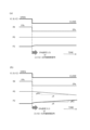
- FIGS. 2(a) and 2(b) show the opening/closing operation of each valve and the temporal changes in the supply pressure P0 and the downstream pressure P2 in the seat leak detection process.
- FIG. 2(a) shows a case where no seat leak occurs
- FIG. 2(b) shows a case where seat leak occurs.
- the flow rate control device 90 has a common inflow path 91 and a common outflow path 92, and a parallel flow path is provided between the common inflow path 91 and the common outflow path 92.
- a first flow path 93a and a second flow path 93b are provided.
- Each parallel flow path 93a, 93b is provided with a control valve 94a, 94b, a first pressure sensor 95a, 95b, and a throttle section 96a, 96b, respectively.
- the common inflow path 91 is provided with an inflow pressure sensor 97 that measures the supply pressure P0 upstream of the control valves 94a, 94b, and the common outflow path 92 is provided with a downstream pressure P0 downstream of the throttle portions 96a, 96b.
- a second pressure sensor 98 is provided to measure P2.
- the opening degree of the control valve 94a is adjusted based on the output (upstream pressure P1) of the first pressure sensor 95a with the control valve 94b of the second flow path 93b completely closed.
- Gas can be supplied at a controlled flow rate in a large flow rate range through a relatively large-diameter constriction portion 96a provided in the first flow path 93a.
- the second flow path Gas can be supplied at a controlled flow rate in a small flow rate range through a relatively small-diameter constriction portion 96b provided at 93b.
- an upstream on-off valve V1 is provided on the upstream side of the flow rate control device 90
- a downstream on-off valve V2 is provided on the downstream side of the flow rate control device 90.
- the fluid system including the flow control device 90 is configured such that the flow path can be blocked both upstream and downstream of the flow control device 90.
- seat leak detection of the control valves 94a and 94b is performed by simultaneously closing the upstream on-off valve V1 and the downstream on-off valve V2, and closing the control valve V1 and the downstream on-off valve V2, as shown in FIGS. Close one of the open sides of 94a and 94b (change the set flow rate input IN from arbitrary X% to 0%, or input a forced close signal to the control valves 94a and 94b) It is done by Hereinafter, in this specification, a description regarding the forced closing signal for the control valves 94a and 94b will be omitted, and a configuration in which the set flow rate is 0% will be described.
- the flow rate control device 90 can perform the seat leak detection process at a timing when the controlled flow rate becomes 0%, such as during a gas supply stop period.
- downstream pressure P2 initially increases is that the upstream pressure P1 between the open control valves 94a, 94b and the corresponding throttle portions 96a, 96b is greater than the downstream pressure P2, and the control valves 94a, 94b This is because even after closing, a small amount of gas flows in through the throttle parts 96a and 96b. Then, after a certain period of time, the differential pressure across the constricted portions 96a and 96b disappears, so the upstream pressure P1 and the downstream pressure P2 become equal in magnitude. Moreover, even after that, as long as the upstream on-off valve V1 and the downstream on-off valve V2 are closed, the upstream pressure P1 and the downstream pressure P2 are usually maintained at the same magnitude.
- the seat It is possible to detect whether or not a leak has occurred.
- ⁇ P0/ ⁇ t or ⁇ P2/ ⁇ t changes depending on the leakage flow rate. More specifically, ⁇ P0/ ⁇ t or ⁇ P2/ ⁇ t is considered to be approximately proportional to the mass flow rate of the leak gas. Therefore, by estimating the leak flow rate from the slope of the measured ⁇ P0/ ⁇ t or ⁇ P2/ ⁇ t and adding this to the normal flow rate, a corrected flow rate as a more accurate flow rate can be obtained.
- FIG. 3 is a diagram showing a more specific example of the seat leakage inspection process.
- a 0% flow rate setting is input, and although not shown here, the upstream on-off valve V1 and the downstream on-off valve V2 are also closed at the same time. .
- the first pressure measurement is performed for the supply pressure P0 and the downstream pressure P2.
- the obtained pressure values P0 1 and P2 1 are stored in memory.
- the next pressure measurement is performed for the supply pressure P0 and the downstream pressure P2, and the pressure values P02 and P2 2 is obtained.
- the first seat leak is detected by comparing the pressure value at time t0 and the pressure value at time t1.
- the pressure difference P0 1 -P0 2 is determined as the pressure fluctuation ⁇ P0
- the pressure difference P2 2 -P2 1 is determined as the pressure fluctuation ⁇ P2.
- the pressure fluctuation ⁇ P0 exceeds a predetermined threshold value (for example, 1.0 kPa) and the pressure fluctuation ⁇ P2 exceeds a predetermined threshold value (for example, 1.5 kPa)
- a predetermined threshold value for example, 1.0 kPa
- a predetermined threshold value for example, 1.5 kPa
- FIG. 3 is a diagram for explaining the mechanism by which detection occurs.
- a command to return to normal operation at an arbitrary control flow rate Y% may be issued immediately before the Nth inspection at time tn after a predetermined time ⁇ t has elapsed.
- the upstream opening/closing valve V1 and the downstream opening/closing valve V2 are simultaneously opened, and the gas from the upstream side is flown to the downstream side after its flow rate is controlled via the flow rate control device 90.
- a delay in the operation control of the flow rate control device 90 may occur, and a case may occur in which the control valves 94a and 94b are not yet opened at the time ta when the command is received.
- the timing of the Nth inspection happens by chance during the period (for example, within 1 second) until the time tb when the opening/closing control of the control valve actually starts and the operation control at the control flow rate Y% is performed.
- the control flow rate is recognized as 0% due to the operation delay, the N-th test is continued without being canceled.
- An exhaust line may be provided upstream of the flow rate control device 10, and the upstream side may be exhausted at the timing of changing the control flow rate. Therefore, when the upstream on-off valve V1 is opened at time ta, there is a case where the supply pressure P0 decreases due to exhaust gas. On the other hand, on the downstream side of the flow rate control device 10, a supply line for diluting gas or the like may be provided. Therefore, when the downstream opening/closing valve V2 is opened at time ta, the downstream pressure P2 may increase in a state where the pressure downstream of the downstream opening/closing valve V2 is higher than that of the downstream opening/closing valve V2.
- the downstream pressure P2 may rise above the threshold value. Therefore, even though no seat leak actually occurred, fluctuations in the supply pressure P0 and downstream pressure P2 satisfied the conditional expression for seat leak determination, which could lead to false detection. .
- the alarm activation condition is first satisfied. Even if this happens, the alarm is not activated immediately, but a re-examination is performed after a set period of time has elapsed, and it is determined whether or not to activate the alarm based on the results.
- FIG. 5 shows a fluid system 100 including a flow control device 10 in which a seat leak detection method according to an embodiment of the present invention is implemented.
- the fluid system 100 includes a gas supply source 2, a flow rate control device 10 for controlling the flow rate of gas supplied from the gas supply source 2, and a process chamber 4 to which gas is supplied via the flow rate control device 10.
- a vacuum pump 6 connected to the process chamber 4 is provided.
- the vacuum pump 6 is used to evacuate the inside of the process chamber and the flow path.
- a gas supply source 2 supplies various gases used in semiconductor manufacturing processes, such as source gas, etching gas, or carrier gas, to the process chamber 4 . Although only one gas supply line is shown in FIG. 5, it goes without saying that a large number of gas supply lines may be connected to the process chamber 4.
- an upstream on-off valve V1 is provided on the upstream side of the flow rate control device 10, and a downstream on-off valve V2 is provided on the downstream side of the flow rate control device 10.
- the fluid system 100 is configured such that the flow path can be blocked both upstream and downstream of the flow control device 10.
- valves with good shutoff performance and responsiveness, such as air-operated valves (AOV), electromagnetic valves (solenoid valves), or electric valves.
- AOV air-operated valves
- solenoid valves solenoid valves
- electric valves An on-off valve is used.
- FIG. 6 shows the flow rate control device 10, the upstream on-off valve V1, and the downstream on-off valve V2 in the fluid system 100 shown in FIG.
- the upstream on-off valve V1 and the downstream on-off valve V2 are provided outside the flow rate control device 10, but they may be incorporated inside the flow rate control device 10.
- the flow rate control device 10 has a common inflow path 11 and a common outflow path 12. Between the common inflow path 11 and the common outflow path 12, there are parallel flow paths 13a and 13b. A first flow path 13a and a second flow path 13b are provided. The parallel flow paths 13a and 13b are provided with control valves 14a and 14b, first pressure sensors (upstream pressure sensors that measure upstream pressure P1) 15a and 15b, and throttle sections 16a and 16b, respectively, to control the flow rate. It is used as a control flow path for this purpose.
- Each flow path 11, 12, 13a, 13b is formed, for example, by a small hole provided in a metal block, but is not limited thereto, and may be formed by piping.
- the common inflow path 11 is provided with an inflow pressure sensor 17 that measures the supply pressure P0 on the upstream side of the control valves 14a, 14b, and the common outflow path 12 is provided with a downstream pressure sensor 17 on the downstream side of the throttle portions 16a, 16b.
- a second pressure sensor (downstream pressure sensor) 18 is provided to measure P2.
- the flow rate control device 10 may have the same configuration as the flow rate control device 90 of the comparative example shown in FIG.
- the inflow pressure sensor 17 may be provided not in the common inflow path 11 but in either of the parallel flow paths 13a and 13b as long as it is upstream of the control valves 14a and 14b. Further, the second pressure sensor 18 may be provided not in the common outflow path 12 but in either of the parallel flow paths 13a and 13b as long as it is downstream of the throttle portions 16a and 16b.
- the flow rate control device 10 may be provided with a temperature sensor for measuring the temperature of the gas.
- a temperature sensor for measuring the temperature of the gas.
- a thermistor can be used as the temperature sensor.
- the output of the temperature sensor can be used to more accurately control the flow rate.
- a piezo element-driven valve which is constituted by a metal diaphragm as a valve body and a piezo element (piezo actuator) as a drive device for driving the metal diaphragm.
- Piezo element-driven valves are configured so that the opening degree can be arbitrarily changed according to the drive voltage applied to the piezo element, and it is possible to adjust the opening degree to any desired value by controlling the drive voltage.
- the inflow pressure sensor 17 the first pressure sensors 15a, 15b, and the second pressure sensor 18, for example, pressure sensors of a type that include a silicon single crystal diaphragm and a sensor chip fixed thereto are used.
- the flow rate control device 10 has a control circuit 19.
- the control circuit 19 includes a CPU provided on a circuit board, a memory (storage device) such as ROM or RAM, an A/D converter, etc., and includes a computer program configured to execute the operations described below. It can be implemented by a combination of hardware and software.
- the control circuit 19 is configured so that during normal flow rate control, the flow rate can be controlled by feedback control of the control valve based on the upstream pressure P1.
- control circuit 19 is configured to be able to detect seat leaks in the control valves 14a and 14b based on the measurement results of supply pressure P0 and downstream pressure P2 (or upstream pressure P1) over time when detecting seat leaks. ing. Some or all of the components of the control circuit 19 may be provided outside the flow rate control device 10, and may be provided as part of an external control unit for controlling the operations of the upstream on-off valve V1 and the downstream on-off valve V2. may be provided.
- the first flow path 13a is used as a control flow path when a large flow rate of gas flows
- the second flow path 13b is used as a control flow path when a small flow rate of gas flows.
- the diameter of the constricted portion 16a provided in the first flow path 13a is larger than the diameter of the constricted portion 16b provided in the second flow path 13b.
- the constricted parts 16a and 16b for example, an orifice plate, a critical nozzle, or a slit structure is used.
- the diameter of the orifice or nozzle is set to, for example, 10 ⁇ m to 2500 ⁇ m.
- control in a large flow rate range is achieved by adjusting the opening degree of the control valve 14a based on the output (upstream pressure P1) of the first pressure sensor 15a with the control valve 14b completely closed. Gas can be supplied at a flow rate.
- the opening degree of the control valve 14b based on the output (upstream pressure P1) of the first pressure sensor 15b with the control valve 14a completely closed, gas is supplied at a controlled flow rate in the small flow range. It can be performed.
- the maximum value of the flow rate that can be controlled by the flow rate control device 10 is 100% (full scale flow rate)
- the first flow path 13a for large flow rate is used when controlling the flow rate in a flow rate range of 5 to 100%, for example.
- the second flow path 13b for small flow rate is used, for example, when controlling the flow rate in a flow rate range of 0.1 to 5%.
- a desired flow rate is obtained by determining the calculated flow rate from the output of the first pressure sensors 15a, 15b (i.e., the upstream pressure P1), and performing feedback control on either of the control valves 14a, 14b so that the calculated flow rate becomes the same as the set flow rate. can be controlled.
- the flow rate Q K2 P2 m (P1 - P2) n (K2 is a proportionality coefficient that depends on the type of fluid and fluid temperature, and the exponents m and n are values derived from the actual flow rate. ), the calculated flow rate is determined from the output of the first pressure sensors 15a, 15b (i.e., upstream pressure P1) and the output of the second pressure sensor 18 (i.e., downstream pressure P2), and the calculated flow rate is made to be the same as the set flow rate. By performing feedback control on either of the control valves 14a, 14b, it is possible to control the flow rate to a desired level.
- control valves 14a and 14b provided in the other flow path be configured so that they can be completely closed.
- a sheet made of resin eg, polychlorotrifluoroethylene (PETFE)
- PETFE polychlorotrifluoroethylene
- a resin sheet is used, the airtightness when the control valve is closed can be improved, so that flow path switching can be performed suitably.
- a resin thin film may be formed on the valve body (metal diaphragm) of the control valves 14a, 14b on the contact surface with the seat.
- Seat leak detection is performed in the same way as in the comparative example shown in FIGS. 2(a), 2(b), and 3, by first closing the upstream on-off valve V1 and the downstream on-off valve V2, which are open, and This is performed by inputting a 0% set flow rate (or inputting a control valve forced close signal) to the flow rate control device 10.
- the upstream on-off valve V1, the downstream on-off valve V2, and the control valves 14a and 14b are all closed.
- the N-th test is re-tested at time tn' (third time) after an additional waiting time ⁇ tr.
- the additional waiting time ⁇ tr is typically set to a smaller value (for example, half or less) than the predetermined time ⁇ t that is the normal inspection interval.
- the additional standby time ⁇ tr is typically set longer than the control delay time that may occur when returning to the normal flow rate control operation described above.
- the additional waiting time ⁇ tr may be set to, for example, 1 to 5 seconds, and may be set as a parameter value that can be changed arbitrarily later.
- the inspection is valid only when the set flow rate input IN is 0%, and when the set flow rate input IN is any Y% flow rate other than 0% (i.e., IN ⁇ 0%), the test is invalidated. Therefore, when shifting to flow rate control at Y% flow rate as shown in Fig. 4, it is necessary that the set flow rate input IN is not 0% at the timing of re-inspection performed after the additional standby time ⁇ tr has elapsed. It is expected that the test itself will be determined to be invalid (the test will not be performed). Therefore, it is possible to prevent erroneous detection of a seat leak, which is not caused by a seat leak but is caused by pressure fluctuations that may occur due to a control delay when transitioning to normal flow rate control.
- the pressure fluctuations ⁇ P0B and ⁇ P2B obtained from the N-1st pressure measurement value and the pressure measurement value at the re-examination both exceed a predetermined threshold value.
- the presence or absence of a seat leak is determined based on whether or not the seat leak occurs, and it is determined whether or not to activate an alarm.
- FIG. 8 is a flowchart showing the procedure of the seat leak detection method according to this embodiment.
- step S1 it is determined whether the set flow rate input IN is other than 0%.
- IN is other than 0% (YES in step S1)
- step S2 the flow is ended as shown in step S2 without proceeding to leak detection.
- step S1 when the set flow rate input IN is 0% (NO in step S1), as shown in step S3, the timer loop TL continues until the initial time ⁇ t0 reaches the set stabilization waiting time Wait for the time to elapse.
- the stabilization waiting time X is, for example, 1 sec.
- step S3 when the stabilization waiting time X has reached (YES in step S3), the first pressure measurement is performed as shown in step S4.
- the supply pressure P0 and the downstream pressure P2 are measured, and the values (here, value A) are stored in the memory.
- step S5 it is determined again whether or not the set flow rate input IN is other than 0%, and if the set flow rate input IN is other than 0%, the sheet Terminate the leak detection flow.
- step S5 when the set flow rate input IN is 0%, the timer loop TL waits until the time ⁇ t reaches the set inspection interval Y, as shown in step S7. Then, when the inspection interval Y is reached, as shown in step S8, the supply pressure P0 and downstream pressure P2 are measured, and the values (here, value B) are stored in the memory.
- the inspection interval Y is, for example, 45 seconds.
- step S9 the obtained pressure measurement values A and B are compared for each of the supply pressure P0 and the downstream pressure P2 to determine whether a seat leak has occurred.
- two conditional expressions are used: whether or not the pressure fluctuation A-B exceeds the threshold value a for the supply pressure P0, and whether or not the pressure fluctuation B-A exceeds the threshold value b for the downstream pressure P2. It is determined whether both are satisfied.
- a is, for example, 1.0 kPa
- b is, for example, 1.5 kPa.
- step S9 When it is determined in step S9 that there is no seat leak, as shown in step S16, B is substituted for A indicating the previous value, the timer is reset, and the process returns to step S5. Thereby, under the condition that the set flow rate input IN is 0%, the next test can be performed continuously after the set test interval Y has elapsed.
- step S9 if both conditional expressions are satisfied, there is a suspicion that a seat leak has occurred, but in this embodiment, instead of issuing an alarm immediately, it is treated as an alarm trigger and is carried out in steps S10 to S14 of the re-detection flow. transition to. Steps S10 to S14 are parts added in the new firmware used in the detection method of this embodiment. In addition, in the detection method of the comparative example described above, when the determination in step S9 is YES, the process directly moves to the step of notifying an alarm in step S15.
- step S10 it is determined whether the set flow rate input IN is other than 0%.
- step S11 it is determined whether the set flow rate input IN is other than 0%.
- step S10 when the set flow rate input IN is 0% in step S10, the seat leak detection flow is continued as shown in step S11. Then, in order to perform the re-inspection, as shown in step S12, the timer loop TL waits until the additional waiting time ⁇ tr reaches the extension time Z.
- the extension time Z is, for example, 5 seconds.
- step S10 During the timer loop until this additional standby time ⁇ tr has elapsed, if it is confirmed in step S10 that the set flow rate input IN is other than 0%, the process moves to step S11 to end the seat leak detection flow. Therefore, at the timing shown in FIG. 4, it is once determined that there is a seat leak in step S9, and then the set flow rate input IN shifts to Y% due to a control delay (usually less than a few seconds). Also, the flow can be ended in step S11 by branching from step S10. Therefore, it is possible to prevent false detections that would otherwise occur due to the pressure fluctuations ⁇ P0 and ⁇ P2 exceeding the threshold values even though no seat leak actually occurs.
- step S13 the supply pressure P0 and downstream pressure P2 are remeasured, and the values (here, the updated value B) are stored in the memory. Then, in step S14, the obtained pressure measurement values A and B (updated values) are compared for each of the supply pressure P0 and the downstream pressure P2 to determine whether a seat leak has occurred.
- the determination made in step S14 is the same as the determination made in step S9, except that update value B is used.
- step S14 may use a different threshold value or determination formula from step S9.
- step S14 if it is determined that there is a seat leak in the re-inspection, an alarm is issued to notify the user of this, and typically the operation of the device is stopped, as shown in step S15.
- the notification alarm in step S15 may be, for example, a sound or light notification, or a warning display on the terminal screen used by the user. This allows the user to recognize the occurrence of seat leak and to know that a problem has occurred in the flow rate control.
- step S14 determines whether there is no seat leak. If it is determined in step S14 that there is no seat leak, it is determined that the determination in step S9 was an accidental false positive, and the process proceeds to step S16, in which B is substituted for A indicating the previous value. The timer is reset and the process returns to step S5. Thereby, under the condition that the set flow rate input IN is 0%, the next test can be performed continuously after the set test interval Y has elapsed.
- T is the gas temperature (° C.)
- ⁇ P0 is the magnitude of pressure drop (Torr)
- ⁇ t is the time (sec) required for the pressure drop of ⁇ P0.
- V is the total volume (liter) of the flow path between the upstream on-off valve V1 and the control valves 14a, 14b.
- the presence or absence of seat leak is detected by referring to the measurement results of both the supply pressure P0 and the downstream pressure P2. This is because in maintenance mode, etc. where the set flow rate is set to 0%, the common inflow path 11 may be evacuated and the supply pressure P0 may be forcibly reduced. In this case, only the supply pressure P0 is referenced. This is because there is a risk that it may be falsely detected that a seat leak has occurred in the control valve, even though no seat leak has actually occurred in the control valve. By referring to both the supply pressure P0 and the downstream pressure P2, the presence or absence of seat leak can be detected more accurately. However, depending on the situation, it is also possible to detect a seat leak by monitoring one of the supply pressure P0 and the downstream pressure P2.
- the downstream pressure P2 is referred to, but in the seat leak detection process, the upstream pressure P1 and the downstream pressure P2 can be considered to be equivalent. Therefore, it is also possible to detect a seat leak by referring to the upstream pressure P1 instead of the downstream pressure P2.
- the downstream pressure P2 which is the output of the second pressure sensor 18 used in both small flow control and large flow control, even if there is a difference in characteristics between the first pressure sensors 15a and 15b, There is less risk of false positives.
- the present invention is not limited to this.
- the presence or absence of seat leakage can also be detected by comparing the slope ⁇ P0/ ⁇ t of the rate of change of the supply pressure P0 and the slope ⁇ P2/ ⁇ t of the rate of change of the downstream pressure P2 with predetermined threshold values.
- Y may be used as ⁇ t
- Y+Z may be used as ⁇ t.
- a pressure sensor used in a pressure-type flow control device is used to detect seat leaks, but even if it is not a pressure-type flow control device, a shutoff valve can be installed upstream and downstream of the flow control device. Similar seat leak detection is possible by providing a pressure sensor before and after the control valve.
- seat leak can also be detected using the same procedure in a flow control device in which three or more flow paths are installed in parallel. can do.
- parallel flow paths it is not necessary that parallel flow paths are provided, and even if only one control flow path is provided, seat leaks in the control valve can be detected using the same procedure as above. .
- the seat leak detection method according to the embodiment of the present invention is suitably used, for example, to detect seat leak of a control valve in a fluid system including a flow rate control device.
Landscapes
- Physics & Mathematics (AREA)
- General Physics & Mathematics (AREA)
- Engineering & Computer Science (AREA)
- General Engineering & Computer Science (AREA)
- Mechanical Engineering (AREA)
- Automation & Control Theory (AREA)
- Examining Or Testing Airtightness (AREA)
- Measuring Volume Flow (AREA)
Priority Applications (2)
| Application Number | Priority Date | Filing Date | Title |
|---|---|---|---|
| KR1020247027982A KR20240135844A (ko) | 2022-06-29 | 2023-06-05 | 컨트롤 밸브의 시트 누설 검지 방법 |
| JP2024530608A JPWO2024004535A1 (https=) | 2022-06-29 | 2023-06-05 |
Applications Claiming Priority (2)
| Application Number | Priority Date | Filing Date | Title |
|---|---|---|---|
| JP2022104288 | 2022-06-29 | ||
| JP2022-104288 | 2022-06-29 |
Publications (1)
| Publication Number | Publication Date |
|---|---|
| WO2024004535A1 true WO2024004535A1 (ja) | 2024-01-04 |
Family
ID=89382734
Family Applications (1)
| Application Number | Title | Priority Date | Filing Date |
|---|---|---|---|
| PCT/JP2023/020791 Ceased WO2024004535A1 (ja) | 2022-06-29 | 2023-06-05 | コントロール弁のシートリーク検知方法 |
Country Status (4)
| Country | Link |
|---|---|
| JP (1) | JPWO2024004535A1 (https=) |
| KR (1) | KR20240135844A (https=) |
| TW (1) | TWI886498B (https=) |
| WO (1) | WO2024004535A1 (https=) |
Citations (5)
| Publication number | Priority date | Publication date | Assignee | Title |
|---|---|---|---|---|
| JPH09113400A (ja) * | 1995-10-17 | 1997-05-02 | Matsushita Electric Ind Co Ltd | 配管漏洩検知装置 |
| JP2010002264A (ja) * | 2008-06-19 | 2010-01-07 | Honda Motor Co Ltd | ガス漏れ診断装置及びガス漏れ診断方法 |
| WO2017110066A1 (ja) * | 2015-12-25 | 2017-06-29 | 株式会社フジキン | 流量制御装置および流量制御装置を用いる異常検知方法 |
| WO2018070464A1 (ja) * | 2016-10-14 | 2018-04-19 | 株式会社フジキン | 流体制御装置 |
| JP2020087164A (ja) * | 2018-11-29 | 2020-06-04 | 株式会社フジキン | コントロール弁のシートリーク検知方法 |
Family Cites Families (1)
| Publication number | Priority date | Publication date | Assignee | Title |
|---|---|---|---|---|
| US5605487A (en) * | 1994-05-13 | 1997-02-25 | Memc Electric Materials, Inc. | Semiconductor wafer polishing appartus and method |
-
2023
- 2023-06-05 JP JP2024530608A patent/JPWO2024004535A1/ja active Pending
- 2023-06-05 WO PCT/JP2023/020791 patent/WO2024004535A1/ja not_active Ceased
- 2023-06-05 KR KR1020247027982A patent/KR20240135844A/ko active Pending
- 2023-06-13 TW TW112121972A patent/TWI886498B/zh active
Patent Citations (5)
| Publication number | Priority date | Publication date | Assignee | Title |
|---|---|---|---|---|
| JPH09113400A (ja) * | 1995-10-17 | 1997-05-02 | Matsushita Electric Ind Co Ltd | 配管漏洩検知装置 |
| JP2010002264A (ja) * | 2008-06-19 | 2010-01-07 | Honda Motor Co Ltd | ガス漏れ診断装置及びガス漏れ診断方法 |
| WO2017110066A1 (ja) * | 2015-12-25 | 2017-06-29 | 株式会社フジキン | 流量制御装置および流量制御装置を用いる異常検知方法 |
| WO2018070464A1 (ja) * | 2016-10-14 | 2018-04-19 | 株式会社フジキン | 流体制御装置 |
| JP2020087164A (ja) * | 2018-11-29 | 2020-06-04 | 株式会社フジキン | コントロール弁のシートリーク検知方法 |
Also Published As
| Publication number | Publication date |
|---|---|
| KR20240135844A (ko) | 2024-09-12 |
| TWI886498B (zh) | 2025-06-11 |
| TW202414139A (zh) | 2024-04-01 |
| JPWO2024004535A1 (https=) | 2024-01-04 |
Similar Documents
| Publication | Publication Date | Title |
|---|---|---|
| KR102250967B1 (ko) | 압력식 유량 제어 장치 및 유량 제어 방법 | |
| JP6892687B2 (ja) | 流量制御装置および流量制御装置を用いる異常検知方法 | |
| CN108027618B (zh) | 压力式流量控制装置及其异常检测方法 | |
| KR101840047B1 (ko) | 가스 유동 제어기의 인 시투 시험을 위한 방법 및 장치 | |
| KR100969210B1 (ko) | 압력식 유량 제어장치의 스로틀 기구 하류측 밸브의 작동 이상 검출방법 | |
| CN109478074B (zh) | 压力式流量控制装置 | |
| TWI534577B (zh) | 壓力式流量控制裝置 | |
| US8112182B2 (en) | Mass flow rate-controlling apparatus | |
| US12174647B2 (en) | Flow rate control device | |
| TW201814254A (zh) | 流量控制機器、流量控制機器的流量校正方法、流量測定機器及使用流量測定機器的流量測定方法 | |
| JP7197897B2 (ja) | コントロール弁のシートリーク検知方法 | |
| TWI719552B (zh) | 流量控制系統及流量測量方法 | |
| JP5442413B2 (ja) | 半導体製造装置および流量制御装置 | |
| WO2024004535A1 (ja) | コントロール弁のシートリーク検知方法 | |
| JP2025093734A (ja) | 流量測定装置 | |
| JP2023018246A (ja) | 圧力式流量制御装置 | |
| KR20100054906A (ko) | 배기 장치 | |
| KR20070014856A (ko) | 유량 조절기의 오작동 감지장치 |
Legal Events
| Date | Code | Title | Description |
|---|---|---|---|
| 121 | Ep: the epo has been informed by wipo that ep was designated in this application |
Ref document number: 23830985 Country of ref document: EP Kind code of ref document: A1 |
|
| ENP | Entry into the national phase |
Ref document number: 20247027982 Country of ref document: KR Kind code of ref document: A |
|
| ENP | Entry into the national phase |
Ref document number: 2024530608 Country of ref document: JP Kind code of ref document: A |
|
| NENP | Non-entry into the national phase |
Ref country code: DE |
|
| 122 | Ep: pct application non-entry in european phase |
Ref document number: 23830985 Country of ref document: EP Kind code of ref document: A1 |