WO2024004403A1 - 電子ペン及び電子ペン用芯体 - Google Patents
電子ペン及び電子ペン用芯体 Download PDFInfo
- Publication number
- WO2024004403A1 WO2024004403A1 PCT/JP2023/017913 JP2023017913W WO2024004403A1 WO 2024004403 A1 WO2024004403 A1 WO 2024004403A1 JP 2023017913 W JP2023017913 W JP 2023017913W WO 2024004403 A1 WO2024004403 A1 WO 2024004403A1
- Authority
- WO
- WIPO (PCT)
- Prior art keywords
- electronic pen
- tip
- pen
- housing
- axial direction
- Prior art date
- Legal status (The legal status is an assumption and is not a legal conclusion. Google has not performed a legal analysis and makes no representation as to the accuracy of the status listed.)
- Ceased
Links
Images



Classifications
-
- B—PERFORMING OPERATIONS; TRANSPORTING
- B43—WRITING OR DRAWING IMPLEMENTS; BUREAU ACCESSORIES
- B43K—IMPLEMENTS FOR WRITING OR DRAWING
- B43K1/00—Nibs; Writing-points
- B43K1/12—Writing-points comprising fibres; Felt pads
-
- G—PHYSICS
- G06—COMPUTING OR CALCULATING; COUNTING
- G06F—ELECTRIC DIGITAL DATA PROCESSING
- G06F3/00—Input arrangements for transferring data to be processed into a form capable of being handled by the computer; Output arrangements for transferring data from processing unit to output unit, e.g. interface arrangements
- G06F3/01—Input arrangements or combined input and output arrangements for interaction between user and computer
- G06F3/03—Arrangements for converting the position or the displacement of a member into a coded form
-
- G—PHYSICS
- G06—COMPUTING OR CALCULATING; COUNTING
- G06F—ELECTRIC DIGITAL DATA PROCESSING
- G06F3/00—Input arrangements for transferring data to be processed into a form capable of being handled by the computer; Output arrangements for transferring data from processing unit to output unit, e.g. interface arrangements
- G06F3/01—Input arrangements or combined input and output arrangements for interaction between user and computer
- G06F3/03—Arrangements for converting the position or the displacement of a member into a coded form
- G06F3/033—Pointing devices displaced or positioned by the user, e.g. mice, trackballs, pens or joysticks; Accessories therefor
- G06F3/0354—Pointing devices displaced or positioned by the user, e.g. mice, trackballs, pens or joysticks; Accessories therefor with detection of two-dimensional [2D] relative movements between the device, or an operating part thereof, and a plane or surface, e.g. 2D mice, trackballs, pens or pucks
- G06F3/03545—Pens or stylus
-
- G—PHYSICS
- G06—COMPUTING OR CALCULATING; COUNTING
- G06F—ELECTRIC DIGITAL DATA PROCESSING
- G06F3/00—Input arrangements for transferring data to be processed into a form capable of being handled by the computer; Output arrangements for transferring data from processing unit to output unit, e.g. interface arrangements
- G06F3/01—Input arrangements or combined input and output arrangements for interaction between user and computer
- G06F3/03—Arrangements for converting the position or the displacement of a member into a coded form
- G06F3/041—Digitisers, e.g. for touch screens or touch pads, characterised by the transducing means
- G06F3/046—Digitisers, e.g. for touch screens or touch pads, characterised by the transducing means by electromagnetic means
Definitions
- the electronic pen is moved by the user on the input surface of the position detection sensor with the tip of the core protruding from the opening on the pen tip side of the housing in contact with the input surface. Then, the movement trajectory of the contact portion of the electronic pen is detected by the position detection sensor as a writing trajectory by the electronic pen.
- the electronic pen is equipped with a pen pressure detection unit that detects the pen pressure applied to the tip of the core
- the fluff at the tip of the core is between the end surface of the opening of the housing and the core. This may increase the friction between the pen and the pen, making it impossible to accurately detect pen pressure.
- An opening having a columnar space having a predetermined length in the axial direction, with the axial direction being the center line direction, is provided on the pen tip side on one end side in the axial direction, and inside, a casing having a hollow portion communicating with the columnar space; a pen pressure detection unit disposed in the hollow part of the housing; One end in the axial direction has a tip portion that can partially protrude outside from the opening on the pen tip side of the columnar space of the opening of the housing, and the other end in the axial direction a core body mounted in a state capable of transmitting pen pressure applied to the tip to the pen pressure detection unit disposed in the hollow portion of the housing; Equipped with The tip of the core body is composed of fibers bundled in the axial direction, and the contact portion that contacts the input surface of the position detection sensor is in a state where the fibers bundled in the axial direction are exposed. and at least a portion of the tip portion that faces the inner peripheral wall surface of the opening on the nib side of the
- the core has a portion that protrudes outward from the opening on the pen tip side, and a portion that faces the inner peripheral wall surface of the opening on the pen tip side of the housing.
- the tip portion is composed of fibers bundled in the axial direction, and the contact portion that contacts the input surface of the position detection sensor has the fibers bundled in the axial direction exposed, and At least the portion of the tip portion facing the inner wall surface of the opening on the pen tip side of the housing is covered with a material harder than the fibers bundled in the axial direction.
- FIG. 1 is a diagram for explaining a configuration example of an embodiment of an electronic pen according to the present invention.
- FIG. 1 is a diagram for explaining an example of the configuration of an embodiment of a core for an electronic pen according to the present invention. It is a figure for explaining the example of composition of other embodiments of the core for electronic pens by this invention. It is a figure for explaining the example of composition of the 1st other embodiment of the electronic pen according to this invention. It is a figure for explaining the other example of composition of the 1st other embodiment of the electronic pen by this invention. It is a figure which shows the comparative example for demonstrating the example of a structure of the 2nd other embodiment of the electronic pen by this invention. It is a figure for explaining the example of composition of the 2nd other embodiment of the electronic pen by this invention. It is a figure for demonstrating the example of a structure of the core body for electronic pens used for the 2nd other embodiment of the electronic pen by this invention.
- FIG. 1 shows a configuration example of an electronic pen 1 according to this embodiment, and this example is an electromagnetic induction type electronic pen.
- the electronic pen 1 of this embodiment has a cylindrical housing 2, which is cylindrical in this example.
- One end side in the axial direction of this housing 2 is a gradually tapered pen nib side, and an opening 21 is provided, and the other end in the axial direction opposite to the pen nib side (referred to as the rear end side) is closed.
- the opening 21 on the pen tip side of the housing 2 is a columnar space whose center line direction is the axial direction and whose length in the axial direction is a predetermined length L.
- It has a cylindrical space having a circular cross section with the same diameter R1.
- the inner circumferential wall surface 21a of the opening 21 is exposed in this columnar space, and this columnar space communicates with the external space through the opening on the pen tip side.
- a coil 3 for position detection In the internal hollow part 2a of the housing 2 of the electronic pen 1, which communicates with the cylindrical space of the opening 21, there is a coil 3 for position detection, a pen pressure detection part 4, and a resonant circuit together with the coil 3.
- Printed circuit boards 6 on which electronic components such as a capacitor 5 are mounted are arranged and housed in order from the pen tip side in the axial direction of the housing 2.
- the ferrite core 7 is provided with a through hole 7a in the axial direction.
- the centerline position of the through hole 7a of this ferrite core 7 is configured to coincide with the centerline position of the opening 21 of the housing 2.
- the diameter R2 of the through hole 7a of the ferrite core 7 is smaller than the diameter R1 of the opening 21 of the housing 2.
- the housing 2, the coil 3, and the ferrite core 7 are shown as cross sections.
- the pen pressure detection part 4 provided on the rear end side of the ferrite core 7 includes a fitting part 9 into which a shaft center part 8S of a core body 8, which will be described later, is fitted.
- the fitting part 9 of the pen pressure detection part 4 is configured to exist on an extension of the through hole 7a of the ferrite core 7.
- the pen pressure detection unit 4 is configured as a variable capacitance capacitor that detects the pressure (pen pressure) applied to the tip of the core 8 as a change in capacitance.
- This type of pen pressure detection unit has a structure in which the capacitance changes by changing the contact area between the dielectric and the conductive elastic member in accordance with the applied pressure (for example, Patent Document: Japanese Patent Laid-Open No. 2016-126503 (see Japanese Patent Application Publication No. 2013-161307), and semiconductor devices in which the distance between two electrodes facing each other with a dielectric air layer in between changes depending on the applied pressure (for example, Patent Document: Japanese Patent Laid-Open No. 2013-161307).
- a well-known method can be used, such as (see publication), and detailed explanation thereof will be omitted here.
- the core body 8 of the embodiment having the configuration described below is inserted into the housing 2 through the cylindrical space of the opening 21, and the ferrite core 7 is inserted into the housing 2 through the cylindrical space of the opening 21. It is configured to pass through the hole 7a and be fitted into and held by a fitting part 9 provided in the pen pressure detection part 4.
- a part of the core body 8 on one end side (pen tip side) in the axial direction is attached to the housing as shown in FIG. It is in a state of protruding to the outside from the opening on the pen tip side of the columnar space of the opening 21 of the body 2.
- FIG. 2 is a diagram for explaining the core 8 of this embodiment, FIG. 2(A) shows the core 8 removed from the electronic pen 1, and FIG. 2(B) shows the core 8.
- the core body 8 is a rod-shaped member with a circular cross section, and as shown in FIGS. It has a configuration in which a shaft center portion 8S extending toward the other end in the direction is integrally coupled.
- the core body 8 of this embodiment is made of felt 81, which is an example of a fiber bundled in the axial direction, so that the shaft center part 8S and the tip part 8T are integrally formed, as shown in FIG. 2(B). It is configured as.
- the felt 81 is constructed by binding fibers together in the axial direction and bonding them together.
- the felt 81 is made of a felt material that is compressed and fixed in the axial direction to increase the strength of the fiber bundle. This makes it possible to configure the provided core body 8 as a molded product made of felt 81.
- the tip portion 8T is made of a material harder than the felt 81, such as a hard resin, over the entire diameter R4 portion, except for the convex curved portion at the tip of the felt 81. It is covered with a hard coating part 82.
- the hard covering portion 82 is made of POM (polyoxymethylene) as an example of hard resin, and is configured to cover the felt 81 with a uniform thickness. Note that the hard material constituting the hard coating portion 82 is not limited to hard resin, and may be, for example, metal.
- the convex curved surface at the tip of the tip portion 8T is not covered with the hard covering portion 82, so the felt 81 is exposed.
- the exposed convex curved portion of the felt 81 is a contact portion 8Tc that contacts the input surface of the position detection sensor at the tip portion 8T of the core body 8.
- the axial length d (see FIGS. 2A and 2B) of the convex curved contact portion 8Tc that is not covered with the hard coating portion 82 is determined by position detection of the tip of the core 8 of the electronic pen 1. The length is sufficient to protrude when writing in contact with the input surface of the sensor.
- the felt 81 is covered with the hard coating 82 except for the contact portion 8Tc, so the diameter R5 of the portion excluding the contact portion 8Tc is the diameter R5 of the felt at the tip 8T.
- the diameter R4 is equal to the thickness of the hard coating portion 82.
- the maximum diameter R5 of the tip 8T is selected to be a value slightly smaller than the diameter R1 of the opening 21 of the housing 2 of the electronic pen 1, as shown in FIG. That is, the relationship R1>R5>R4>R3 is selected.
- the contact portion 8Tc side of the hard coating portion 82 is gradually moved so that the outer diameter approaches the diameter R4 from R5.
- the tapered portion 82t is such that it becomes smaller. Therefore, in the electronic pen 1 of this embodiment, when the contact portion 8Tc of the core body 8 is brought into contact with the input surface of the position detection sensor for writing input, the boundary between the contact portion 8Tc and the hard coating portion 82 is It is constructed so that there are almost no steps. This has the effect that the entire contact portion 8Tc having the length d can be effectively used as a contact portion with the input surface.
- the core body 8 of this embodiment is configured so that there is almost no step at the boundary between the contact portion 8Tc and the hard coating portion 82, so the entire contact portion 8Tc having the length d is used effectively. It can be used as a contact part.
- the core 8 configured as described above is inserted into the housing 2 through the opening 21 of the housing 2 of the electronic pen 1 from the axis 8S side, and the axis 8S is inserted into the through hole of the ferrite core 7. 7a. Then, the end of the shaft center portion 8S of the core body 8 is fitted into the fitting portion 9 provided in the pen pressure detection unit 4, and the core body 8 is attached to the electronic pen 1.
- the mounted core body 8 can be pulled out by grasping the portion protruding outward from the opening 21 of the housing 2. That is, in the electronic pen 1 of this embodiment, the core body 8 is removable and replaceable.
- the contact part 8Tc and a part of the hard coating part 82 protrude outside from the opening part 21 of the housing 2, and the remaining part of the hard coating part 82 extends from the housing.
- the length of the core body 8 in the axial direction, the length of the ferrite core 7 in the axial direction, etc. are selected so that it faces the inner circumferential wall surface 21a exposed in the cylindrical space of the opening 21 of the body 2. has been configured.
- the electronic pen 1 of this embodiment as shown in FIG. A part of the inner peripheral wall surface 21a exposed to the columnar space of the opening 21 of the housing 2 faces the inner peripheral wall surface 21a, and the portion facing the inner peripheral wall surface 21a may be rubbed.
- the housing 2 There is a possibility that the inner circumferential wall surface 21a of the opening 21 and the outer circumferential surface of the tip 8T of the core body 8 may come into contact and cause rubbing.
- the tip 8T of the core body 8 it is not the felt 81 that faces the inner circumferential wall surface 21a of the opening 21 of the housing 2, but the hard coating 82. Therefore, the contact portion with the inner circumferential wall surface 21a of the opening 21 of the casing 2 becomes a part of the hard coating 82, and the felt 81 and the inner circumferential wall surface 21a of the opening 21 of the casing 2 are prevented from rubbing against each other. Therefore, it is possible to prevent the felt 81 from becoming fluffed in the corresponding portion.
- the maximum outer diameter R5 of the tip 8T of the core 8 is made smaller than the diameter R1 of the opening 21 of the housing 2 of the electronic pen 1, and the hard coating of the tip 8T of the core 8
- a gap is formed between the outer peripheral surface of the portion 82 and the inner peripheral wall surface 21a of the opening 21 of the housing 2 of the electronic pen 1, but in this embodiment, at the tip 8T of the core body 8, Since it is not the felt 81 but the hard covering part 82 that faces the inner circumferential wall surface 21a, there is no need to consider the occurrence of fuzz on the felt 81, and this gap can be selected to be as small as possible.
- the core 8 moves according to the magnitude of the applied pen pressure.
- the pen pressure is transmitted to the pen pressure detection section 4 by moving in the axial direction.
- the contact portion is the hard coating portion 82 of the tip portion 8T of the core body 8.
- the pen pressure detection part 4 will be The detected pen pressure value may be affected.
- the felt 81 at the tip 8T of the core body 8 is covered with the hard covering part 82, the influence of the fluff of the felt 81 does not occur, and the pen pressure detection part 4 is , the writing pressure applied to the tip of the core body 8 can be accurately detected.
- the axial center portion 8S of the core body 8 is smaller than the diameter R5 of the tip portion 8T, so that the inner circumferential wall surface 21a of the opening 21 of the housing 2 and the axial center portion 8S are opposed to each other.
- the gap between the two parts becomes relatively large.
- the diameter of the felt 81 is selected so that the diameter R4 at the tip 8T is larger than the diameter R3 at the shaft center 8S. , the gap between the axial center portion 8S and the opposing portion is larger. Therefore, the felt 81 portion of the shaft center portion 8S hardly rubs against the inner circumferential wall surface 21a of the opening 21 of the housing 2.
- the tip portion 8T of the core body 8 includes a contact portion 8Tc that is not covered with the hard coating portion 82, so that the indicated position can be detected on the input surface of the position detection sensor by this contact portion 8Tc. You can input with good accuracy and the electronic pen is easy to use.
- the hard coating 82 prevents friction between the inner peripheral wall surface 21a of the opening 21 of the housing 2 of the electronic pen 1 and the felt 81 of the core 8. Even if the felt 81 is used as the material of the body 8, the pen pressure detection unit 4 can effectively detect the pen pressure accurately by suppressing the influence of the fluff of the felt.
- the pen pressure detection unit 4 detects the contact between the contact portion 8Tc of the core body 8 and the input surface of the position detection sensor and starts detecting the pen pressure value.
- the value of the so-called ON load also has the effect of being lighter than when the felt 81 is exposed at the tip 8T.
- the felt 81 is made of a felt material whose strength is increased by compressing it in the axial direction, and the tip portion 8T and the shaft center portion 8S are configured as an integral part of the felt 81. Therefore, the core body 8 has an effect that the structure is simpler, easier to manufacture, and the manufacturing cost can be lowered than in the cases of Patent Document 1 and Patent Document 2 described above.
- the felt 81 has different diameters between the tip portion 8T and the shaft center portion 8S.
- a felt 81A may be used in which the tip portion 8AT and the shaft center portion 8AS have the same diameter.
- the tip 8AT of the felt 81A is covered with a hard coating 82A except for the contact portion 8ATc.
- the contact portion 8ATc side of the hard coating portion 82A is a tapered portion 82At.
- the felt 81 of the shaft center portion 8S was left exposed.
- the tip end 8BT of the felt 81B is covered with a hard coating part 82B except for the contact part 8BTc.
- the contact portion 8BTc side of the hard coating portion 82B is a tapered portion 82Bt.
- both the tip end portion 8T and the shaft center portion 8S were configured as molded products of the felt 81.
- the shaft center portion may be configured as a separate component from the core body portion.
- the core body 8C in the example of FIG. 3(C) has a structure in which the shaft center portion 8CS is constituted by a pipe 84 made of a hard material, for example, metal, and the tip portion 8CT is attached to this pipe 84.
- the tip portion 8CT in this example is, like the core body 8 in the above example, covered with a hard coating portion 82C except for the contact portion 8CTc at the tip of a bullet-shaped felt 81C, for example.
- the contact portion 8CTc side of the hard coating portion 82C is a tapered portion 82Ct.
- a predetermined member 85 is fitted to close the rear end side of the hollow portion 84a of the pipe 84 in the shaft center portion 8CS.
- the predetermined member 85 may be made of felt or other material. Further, the rear end side of the hollow portion 84a of the pipe 84 in the shaft center portion 8CS may remain open without being closed.
- the strength of the core body can be further increased.
- a knock-type electronic pen can also be constructed in which a cartridge-type electronic pen main body is retracted and retracted in a knock-type manner.
- FIG. 4 is a diagram showing a configuration example of an embodiment of an electronic pen 1A according to a first other embodiment of the present invention, in which an electronic pen main body is housed in a housing 2A as an electronic pen cartridge 30. It is said that In this embodiment, the electronic pen cartridge 30 is removably attached to the housing 2A.
- This example is the case of an electromagnetic induction type electronic pen.
- the electronic pen 1A of this embodiment has a hollow part 2Aa inside a cylindrical housing 2A (hereinafter referred to as pen housing 2A in the description of this embodiment).
- the electronic pen cartridge 30 is housed in a knock type structure in which the pen tip side of the electronic pen cartridge 30 is inserted and removed from an opening 21A at one end in the axial direction of the pen housing 2A by a knock cam mechanism 40. Equipped with.
- the pen housing 2A and the knock cam mechanism section 40 provided in the pen housing 2A are, as shown in FIG. It has the same structure as the outer casing and knock cam function of a ballpoint pen.
- the cam body 41 is formed on the inner wall surface of the cylindrical pen housing 2A.
- the end portion 42a of the knock rod 42 protrudes from the opening 2Ab on the side opposite to the pen tip side of the pen housing 2A so that the knock rod 42 can receive a knock operation by the user.
- the rotor 43 includes a fitting part 43a into which an end of the electronic pen cartridge 30 opposite to the pen tip side is removably fitted.
- the signal transmitting member 31 includes a coil 311 that constitutes a resonant circuit for transmitting and receiving signals to and from the position detection sensor using electromagnetic induction, and a magnetic core around which the coil 311 is wound, in this example a ferrite core 312. It is configured. A through hole 312a is formed at the center of this ferrite core 312 in the axial direction.
- the core body 8 of the embodiment described using FIGS. 1 and 2 is inserted through the through hole 312a of the ferrite core 312 and fitted into the fitting part 9A of the pen pressure detection part 4A.
- the electronic pen cartridge 30 is then removably attached to the electronic pen cartridge 30.
- the pressure (writing pressure) applied to the contact portion 8Tc at the tip of the pen tip side of the core body 8 is applied to the writing pressure detection portion 4A.
- the knock bar 42 is pushed in by the user, and the knock cam mechanism 40 causes the pen tip side of the electronic pen cartridge 30 to protrude from the opening 21A of the pen housing 2A.
- the tip 8T of the core 8 has a contact portion 8Tc and a part of the hard covering portion 82 protruding from the opening 21A of the pen housing 2A,
- the length of the core body 8 in the axial direction and the ferrite core 312 are adjusted so that the remaining part of the covering part 82 faces the inner circumferential wall surface 21Aa forming the columnar space of the opening 21A of the housing 2A.
- the length in the axial direction of the knock cam mechanism 40, the size of the knock stroke by the knock cam mechanism 40, etc. are selected and configured.
- the electronic pen cartridge 30 is moved in the axial direction in a knocking manner, and the tip 8T of the core body 8 attached to the electronic pen cartridge 30 is ejected and retracted. Even when the felt 81 of the tip 8T is covered with the hard coating part 82, there is no friction between the felt 81 and the inner peripheral wall surface of the opening 21 of the housing 2, and the felt 81 fuzz can be prevented.
- the core body to be attached to the electronic pen cartridge 30 is not limited to the core body 8 of the above-mentioned example, but may include the core bodies 8A, 8B, 8C of other examples shown in FIG. 3, and other modifications. It goes without saying that the core body described above may also be used.
- the core 8 is configured to be detachable from the electronic pen cartridge 30.
- the core may be configured to be fixedly attached to the electronic pen cartridge.
- the signal transmitting member 31D is composed of a coil 311 and a ferrite core 312D.
- the ferrite core 312D does not have an axial through hole, but instead has a fitting recess 312Da on the pen tip side.
- the core body 8D does not have an axial center portion and has only a tip portion 8DT.
- the tip end 8DT of the core body 8D is provided with a fitting protrusion 8DTa on the rear end side of the felt 81D, which is fitted into the fitting recess 312Da of the ferrite core 312D.
- the fitting convex portion 8DTa protruding toward the rear end side of the tip portion 8DT is fitted into the fitting recess 312Da of the ferrite core 312D, and by, for example, gluing both, the core is attached to the pen tip side of the ferrite core 312D.
- the distal end 8BT of the body 8D is fixedly attached.
- the tip 8DT of the core 8D has a contact portion 8DTc where the felt 81D is exposed, and also includes a portion covered with a hard covering portion 82D, as in the above embodiment.
- the knock bar 42 When the knock bar 42 is pushed in by the user and the knock cam mechanism 40 causes the pen tip side of the electronic pen cartridge 30D to protrude from the opening 21A of the pen housing 2A, the state is shown in FIG. 4(B).
- the contact part 8DTc and a part of the hard coating part 82D protrude outside from the opening 21A of the pen housing 2A, and the remaining part of the hard coating part 82D A portion thereof is configured to face an inner circumferential wall surface 21Aa exposed in the columnar space of the opening 21A of the housing 2A.
- the core body 8D is fixed to the ferrite core 312D, so in order to detect the writing pressure applied to the contact portion 8DTc of the core body 8D, the following procedure is performed. It is configured.
- the cartridge housing section 32 is composed of a first cylindrical body section 321 in which an electronic circuit component is disposed, and a second cylindrical body section 322 in which a pen pressure detection component is disposed. be done. Inside the first cylindrical body part 321, as shown in FIG. A circuit component 34 is provided. In the first cylindrical body part 321, as shown in FIG. 4(B), the winding start end 311a and the winding end end 311b of the coil 311 are electrically connected to one end and the other end of the capacitor. be made to be done.
- the second cylindrical body part 322 is divided into two parts, a long part 322a and a short part 322b, and a pen pressure detection part 36 is provided near the joint part 35.
- the long portion 322a and the short portion 322b are connected at the connecting portion 25 via a connecting rod member 351 and a coil spring 352.
- the long part 322a and the short part 322b are always elastically displaced apart from each other in the axial direction by the coil spring 352, but are locked at a predetermined position by the connecting rod member 351. It is configured not to be displaced further in the axial direction.
- the long portion 322a is provided with a pen pressure detection section 36.
- One end 351a side of the connecting rod member 351 is configured to function as a pressing part of the pen pressure detection part 36.
- the pen pressure detection section 36 in this example also has a well-known composition of pen pressure described in, for example, patent documents: JP-A No. 2011-186803 and JP-A No. 2013-161307. It uses a detection means and is configured as a variable capacitor whose capacitance changes depending on the pen pressure. In this embodiment, this variable capacitor is connected in parallel to a resonant circuit composed of the coil 311 and the aforementioned capacitor.
- the entire elongated portion 322a side of the electronic pen cartridge 30D springs into a coil spring state.
- a force that tries to move toward the short portion 322b acts against the elastic force of the pen 352, and the capacitance of the pen pressure detection section 36 becomes responsive to the pen pressure. Therefore, as a result, the resonant frequency of the resonant circuit changes due to the capacitance corresponding to the writing pressure applied to the contact portion 8DTc of the core 8D, which is detected by the writing pressure detection unit 36, and as a change in the resonant frequency.
- the pen pressure value is transmitted to the position detection sensor side.
- the electronic pen of the second other embodiment is an example in which this problem can be solved, and is characterized by the configuration of the pen tip side of the housing.
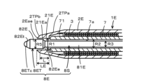
- FIG. 7 is a diagram showing the pen tip side of the electronic pen 1E of this second other embodiment, and the same parts as the electronic pen 1 described using FIG. 1 are given the same reference numerals.
- FIG. 8 is a cross-sectional view for explaining a configuration example of a core body 8E used in an electronic pen 1E of this second other embodiment.
- the electronic pen 1E of this embodiment is different from the housing 2 of the electronic pen 1 of the above-described embodiment in the configuration of the pen tip side of the housing 2E.
- a tapered portion 2TPa whose thickness gradually decreases toward the opening of the opening 21 is formed.
- the tip end side of the tapered portion 2TPa is a ring-shaped end surface 2R that is a plane in a direction orthogonal to the axial direction. That is, the inner peripheral edge (circular edge in this example) 21ae of the opening on the pen tip side of the opening 21 of the inner peripheral wall surface 21a exposed in the cylindrical space of the opening 21 of the housing 2 is the pen tip of the housing 2.
- the tip of the pen tip side of the housing 2E of the electronic pen 1E of this embodiment has an inner peripheral wall surface 21Ea exposed in the columnar space of the opening 21E.
- a tapered portion 2TPb is formed so that the thickness gradually decreases (in this example, the diameter gradually decreases) toward the inner peripheral edge 21Eae of the opening on the pen tip side of the opening 21E. That is, at the tip of the pen tip side of the housing 2E of the electronic pen 1E of this embodiment, the ring-shaped end surface 2R of the plane in the direction orthogonal to the axial direction as shown in FIG. 6 is not formed. Instead, following the tapered part 2TPa (first tapered part), a tapered part 2TPb (second tapered part) is formed further toward the inner peripheral edge 21ae of the opening on the pen tip side of the opening 21E. A tapered portion) is formed.
- the length in the axial direction of the cylindrical space of the opening 21E on the pen tip side of the housing 2E of the electronic pen 1E of this embodiment is the same as that of the electronic pen 1 of the example of FIG. LE is longer than the length L by the taper portion 2TPb.
- the inclination angle of the tapered part 2TPb (second tapered part) with respect to the axial direction is larger.
- the inclination angle of the tapered part 2TPb with respect to the axial direction is larger than the inclination angle of the tapered part 2TPa with respect to the axial direction;
- the inclination angle with respect to the axial direction of the tapered part 2TPa may be smaller than the inclination angle with respect to the axial direction of the tapered part 2TPb.
- the angles of inclination with respect to the direction may be equal.
- the tapered part 2TPb is formed so as to smoothly continue from the tapered part 2TPa without creating a step, but it may occur that the tapered part 2TPb continues smoothly from the tapered part 2TPa.
- the tapered portion 2TPa and the tapered portion 2TPb may be formed in this state.
- the core 8E for the electronic pen 1E of this embodiment is configured as shown in FIG. 8. That is, the core body 8E of this example has a bullet-shaped curved surface on the pen tip side of the felt 81E of the rod-like member with respect to a cylindrical rod-like member of the felt 81E having a diameter slightly smaller than the diameter R3 of the shaft center portion 8ES. The entire convex portion except for the contact portion 8ETc is covered with a hard covering portion 82E.
- the length in the axial direction of the tip 8ET of the core 8E in this example is such that the diameter gradually decreases from the side opposite to the pen tip side of the hard coating 82E having a diameter of R5 toward the axial center 8ES.
- the tip portion 8T of the core body 8 in the example of FIG. 1 is longer by the amount of the tapered portion 82Ee.
- the opening 21E is formed toward the inner peripheral edge 21ae of the opening on the pen tip side.
- a tapered portion 2TPa is formed, and the length LE in the axial direction of the cylindrical space of the opening 21E is equal to the axial length LE of the cylindrical space of the cylindrical space of the opening 21 of the housing 2 of the electronic pen 1 in the example of FIG. It is made longer than the length L of.
- the tip of the core 8E can be prevented from approaching the opening on the tip side of the cylindrical space of the opening 21 of the housing 2 of the electronic pen 1, and the core body 8E can be prevented from approaching the tip end side.
- the problem of bending near the boundary between 8ET and the shaft center portion 8ES can be improved.
- the boundary between the tip 8ET and the shaft center 8ES is not a step formed by a vertical wall, but a portion of the hard coating 82E with a maximum diameter of R5 of the tip 8ET. It has a tapered portion 82Ee whose diameter gradually decreases from the side opposite to the tip side toward the shaft center portion 8ES. Therefore, the length of the tip 8ET in the axial direction is substantially longer than the tip 8T of the core 8, and the presence of the tapered portion 82Ee makes the core 8E more difficult to bend.
- the core body 8E of the electronic pen 1E of the second other embodiment described above has a structure in which the tip portion 8ET and the shaft center portion 8ES excluding the contact portion 8ETc are covered with a hard coating portion 82E.
- the core bodies 8, 8A, 8B, and 8C may have the same configuration as those described above.
- the configuration of the electronic pen 1E and the core body 8E of the second other embodiment described above can also be applied to an electronic pen and a core body using a core body made of a material other than felt, and the bending of the core body is prevented. It can be configured as follows. For example, even if the core body 8E in the example of FIG. 8 uses, for example, an elastomer instead of the felt 81E and uses, for example, POM as the hard coating portion 82E, the effect of preventing the core body from bending can be expected. can.
Landscapes
- Engineering & Computer Science (AREA)
- General Engineering & Computer Science (AREA)
- Theoretical Computer Science (AREA)
- Physics & Mathematics (AREA)
- Human Computer Interaction (AREA)
- General Physics & Mathematics (AREA)
- Electromagnetism (AREA)
- Pens And Brushes (AREA)
Priority Applications (3)
| Application Number | Priority Date | Filing Date | Title |
|---|---|---|---|
| JP2024530355A JPWO2024004403A1 (https=) | 2022-07-01 | 2023-05-12 | |
| CN202380041361.8A CN119156587A (zh) | 2022-07-01 | 2023-05-12 | 电子笔及电子笔用芯体 |
| US19/003,993 US20250138652A1 (en) | 2022-07-01 | 2024-12-27 | Electronic pen and electronic pen core body |
Applications Claiming Priority (2)
| Application Number | Priority Date | Filing Date | Title |
|---|---|---|---|
| JP2022106772 | 2022-07-01 | ||
| JP2022-106772 | 2022-07-01 |
Related Child Applications (1)
| Application Number | Title | Priority Date | Filing Date |
|---|---|---|---|
| US19/003,993 Continuation US20250138652A1 (en) | 2022-07-01 | 2024-12-27 | Electronic pen and electronic pen core body |
Publications (1)
| Publication Number | Publication Date |
|---|---|
| WO2024004403A1 true WO2024004403A1 (ja) | 2024-01-04 |
Family
ID=89382631
Family Applications (1)
| Application Number | Title | Priority Date | Filing Date |
|---|---|---|---|
| PCT/JP2023/017913 Ceased WO2024004403A1 (ja) | 2022-07-01 | 2023-05-12 | 電子ペン及び電子ペン用芯体 |
Country Status (4)
| Country | Link |
|---|---|
| US (1) | US20250138652A1 (https=) |
| JP (1) | JPWO2024004403A1 (https=) |
| CN (1) | CN119156587A (https=) |
| WO (1) | WO2024004403A1 (https=) |
Cited By (1)
| Publication number | Priority date | Publication date | Assignee | Title |
|---|---|---|---|---|
| CN118363472A (zh) * | 2024-04-30 | 2024-07-19 | 深圳市德易盛科技有限公司 | 笔芯及其制备方法、电子笔、智能终端 |
Citations (7)
| Publication number | Priority date | Publication date | Assignee | Title |
|---|---|---|---|---|
| JPH0816300A (ja) * | 1994-06-29 | 1996-01-19 | Sharp Corp | ペン入力装置の入力用ペン |
| JPH10161796A (ja) * | 1996-12-03 | 1998-06-19 | Mitsubishi Pencil Co Ltd | 静電容量型座標入力パッド用入力ペン |
| JP2010020406A (ja) * | 2008-07-08 | 2010-01-28 | Wacom Co Ltd | 位置指示器用芯及び位置指示器 |
| JP2012108896A (ja) * | 2010-10-28 | 2012-06-07 | Mitsubishi Pencil Co Ltd | 情報入力用ペン |
| JP2015005106A (ja) * | 2013-06-20 | 2015-01-08 | 司フエルト商事株式会社 | タッチペン |
| JP2021093040A (ja) * | 2019-12-12 | 2021-06-17 | 株式会社ワコム | 電子ペン |
| WO2021157517A1 (ja) * | 2020-02-07 | 2021-08-12 | 株式会社ワコム | 電子ペン用芯体 |
Family Cites Families (4)
| Publication number | Priority date | Publication date | Assignee | Title |
|---|---|---|---|---|
| WO2013179291A1 (en) * | 2012-05-31 | 2013-12-05 | N-Trig Ltd. | Writing tip for a stylus |
| JP6487694B2 (ja) * | 2014-12-26 | 2019-03-20 | 株式会社ワコム | 位置指示器及び信号処理装置 |
| JP6767252B2 (ja) * | 2016-12-09 | 2020-10-14 | 株式会社ワコム | 電子ペン |
| JP7514826B2 (ja) * | 2019-05-20 | 2024-07-11 | 株式会社ワコム | 電子ペン用芯体及び電子ペン |
-
2023
- 2023-05-12 JP JP2024530355A patent/JPWO2024004403A1/ja active Pending
- 2023-05-12 CN CN202380041361.8A patent/CN119156587A/zh active Pending
- 2023-05-12 WO PCT/JP2023/017913 patent/WO2024004403A1/ja not_active Ceased
-
2024
- 2024-12-27 US US19/003,993 patent/US20250138652A1/en active Pending
Patent Citations (7)
| Publication number | Priority date | Publication date | Assignee | Title |
|---|---|---|---|---|
| JPH0816300A (ja) * | 1994-06-29 | 1996-01-19 | Sharp Corp | ペン入力装置の入力用ペン |
| JPH10161796A (ja) * | 1996-12-03 | 1998-06-19 | Mitsubishi Pencil Co Ltd | 静電容量型座標入力パッド用入力ペン |
| JP2010020406A (ja) * | 2008-07-08 | 2010-01-28 | Wacom Co Ltd | 位置指示器用芯及び位置指示器 |
| JP2012108896A (ja) * | 2010-10-28 | 2012-06-07 | Mitsubishi Pencil Co Ltd | 情報入力用ペン |
| JP2015005106A (ja) * | 2013-06-20 | 2015-01-08 | 司フエルト商事株式会社 | タッチペン |
| JP2021093040A (ja) * | 2019-12-12 | 2021-06-17 | 株式会社ワコム | 電子ペン |
| WO2021157517A1 (ja) * | 2020-02-07 | 2021-08-12 | 株式会社ワコム | 電子ペン用芯体 |
Cited By (1)
| Publication number | Priority date | Publication date | Assignee | Title |
|---|---|---|---|---|
| CN118363472A (zh) * | 2024-04-30 | 2024-07-19 | 深圳市德易盛科技有限公司 | 笔芯及其制备方法、电子笔、智能终端 |
Also Published As
| Publication number | Publication date |
|---|---|
| US20250138652A1 (en) | 2025-05-01 |
| JPWO2024004403A1 (https=) | 2024-01-04 |
| CN119156587A (zh) | 2024-12-17 |
Similar Documents
| Publication | Publication Date | Title |
|---|---|---|
| US11880514B2 (en) | Electronic pen and electronic pen body portion | |
| CN107521259B (zh) | 书写工具和电子笔主体部 | |
| CN111033450B (zh) | 输入触屏笔 | |
| US11714498B2 (en) | Electronic pen core body and electronic pen | |
| WO2024004403A1 (ja) | 電子ペン及び電子ペン用芯体 | |
| US12602120B2 (en) | Electronic pen having knock mechanism to push and retract electronic pen main body out of and into pen housing | |
| WO2019107023A1 (ja) | 多機能ペン | |
| JP7756959B2 (ja) | フェライトコア及びこれを含むスタイラスペン{ferrite cores and stylus pen including the same} | |
| JP7646442B2 (ja) | 電子ペン用芯体及び電子ペン本体部 | |
| KR102807520B1 (ko) | 페라이트 코어 및 이를 포함하는 스타일러스 펜 | |
| JPWO2024004403A5 (https=) | ||
| WO2019045018A1 (ja) | 入力タッチペン | |
| JP2019207673A (ja) | 入力タッチペン | |
| JP7117144B2 (ja) | 入力ペン | |
| JP2024015944A (ja) | 電子ペン及び電子ペン本体部 | |
| JP7053100B2 (ja) | 入力タッチペン | |
| CN117453053A (zh) | 电子笔及电子笔主体部 | |
| WO2024057804A1 (ja) | 電子ペン | |
| JP2026501409A (ja) | スタイラスペン | |
| WO2023132170A1 (ja) | 電子ペン | |
| JP2026002782A (ja) | シーリング部材を含むスタイラスペン{stylus pen including a sealing member} |
Legal Events
| Date | Code | Title | Description |
|---|---|---|---|
| 121 | Ep: the epo has been informed by wipo that ep was designated in this application |
Ref document number: 23830855 Country of ref document: EP Kind code of ref document: A1 |
|
| ENP | Entry into the national phase |
Ref document number: 2024530355 Country of ref document: JP Kind code of ref document: A |
|
| WWE | Wipo information: entry into national phase |
Ref document number: 202380041361.8 Country of ref document: CN |
|
| NENP | Non-entry into the national phase |
Ref country code: DE |
|
| 122 | Ep: pct application non-entry in european phase |
Ref document number: 23830855 Country of ref document: EP Kind code of ref document: A1 |